1
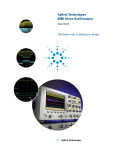
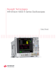
Agilent Technologies InfiniiVision
6000 Series Oscilloscopes
Data Sheet
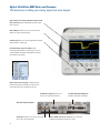
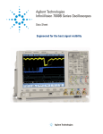
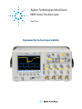
Engineered for the best signal visibility
If you haven’t purchased an Agilent scope lately,
why should you consider one now?
Agilent has been the fastest growing oscilloscope supplier since 1997 (source: Prima
Data, 2007). Wonder why? Agilent engineers developed the InfiniiVision 6000 Series with
advanced technology that will allow you to see more subtle signal detail and more
infrequent events than any other scope on the market. See the InfiniiVision 6000
There is no better way to experience
the superiority of the InfiniiVision 6000
Series scopes than to see it.
Contact Agilent today to request an
evaluation.
Or visit:
www.agilent.com/find/mso6000
Series oscilloscope—the industry’s best for signal viewing.
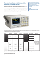
The InfiniiVision 6000 Series offers bandwidths up to 1 GHz. Each model, equipped with a 6.3” XGA LCD display, comes in
a whisper-quiet package that weighs only 11 pounds.
Model
Bandwidth
Sample rate
Memory
DSO6012A
DSO6014A
MSO6012A
Scope channels
100 MHz
2 GSa/s
8 Mpts
2
4
DSO6032A
2
MSO6032A
Update rate
4
MSO6014A
DSO6034A
Digital channels
2
300 MHz
2 GSa/s
8 Mpts
16
4
Up to 100,000
2
deep-memory waveforms
16
MSO6034A
4
DSO6052A
2
deep memory, digital
DSO6054A
4
channels and serial
MSO6052A
500 MHz
4 GSa/s
8 Mpts
2
MSO6054A
4
DSO6102A
2
DSO6104A
MSO6102A
1 GHz
4 GSa/s
MSO6104A
8 Mpts
per second, even with
decode turned on.
16
4
2
4
16
Choose from sixteen InfiniiVision 6000 Series models. Agilent provides an easy 5-minute DSO-to-MSO upgrade kit for
previously purchased 6000 Series DSOs.
2
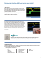
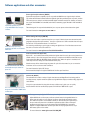
What gives the InfiniiVision 6000 Series the best signal visibility?
1. High resolution
Oscilloscopes are visual tools and high-resolution screens make the
product better. High resolution displays have become increasingly important as general purpose scopes need to display digital and serial signals
in addition to traditional scope channels.
View up to 20 channels simultaneously with serial protocol. See subtle
signal detail with up to 256 levels of intensity.
2. Fastest architecture
See a display more representative of the actual signals under test than
with any other scope. The InfiniiVision 6000 Series shows jitter, infrequent
events, and subtle signal detail that other scopes miss. Turn knobs and the
instrument responds instantly and effortlessly. Need to also view digital
channels? The instrument stays responsive. Decoding serial packets? Offering the industry’s only hardware-accelerated serial bus decode, Agilent’s
InfiniiVision series delivers serial debug without compromising analog
measurements.
InfiniiVision scopes incorporate acquisition memory, waveform processing, and display memory in an
advanced 0.13 µ ASIC. This patented 3rd generation technology, known as MegaZoom III, delivers up to
100,000 waveforms (acquisitions) per second with responsive deep memory always available.
3. Insightful applications
Customize your general purpose scope. A wide range of application packages provide meaningful insight into your application-specific problems. (See pages 8-10 for more detail.)
• Serial with hardware-accelerated decode
▪
▪
▪
▪
▪
I2C, SPI
I2S
CAN/LIN
RS-232/UART
DSO/MSO offline analysis
▪
▪
▪
▪
▪
Core-assisted FPGA debug
Vector signal analysis
Segmented memory
Mask testing
Power measurement
▪ Secure environment
▪ FlexRay
▪ MIL-STD 1553
3
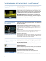
Your design has analog, digital and serial signals ... shouldn’t your scope?
Analog: Up to 1 GHz bandwidth and up to
4 GSa/s sample rate
The InfiniiVision 6000 Series scope channels provide faster identification of
your most elusive problems –
Revolutionary high-resolution display. Engineered with an XGA display and 256 levels
of intensity grading, see a precise representation of the analog characteristics of the
signals you’re testing. Equipped with the industry’s fastest uncomprimised update rate
at 100,000 waveforms/sec update rate, you’ll capture critical signal detail and see
infrequent events that traditional scopes miss.
MegaZoom III technology. MegaZoom III responsive deep memory captures long,
non-repeating signals and maintains high sample rates, allowing you to quickly zoom
in on areas of interest. Sample rate and memory depth go hand-in-hand. Deep memory
in oscilloscopes sustains a high sample rate over longer time spans.
Digital: 16 digital timing channels with
mixed signal triggering
Capture a mix of analog or digital signals. Compare multiple cycles of digital signals
with slower analog signals –
16 high-speed timing channels with up to 2 GSa/s deep memory. Use the timing
channels to evaluate control signal relationship. Or capture and view data buses up
to 16 bits wide. Trigger on and display individual signals or bus waveforms in hex or
binary.
Mixed signal trigger.
Trigger across any combination of analog and digital signals simultaneously. See precise analog measurements timed with exact digital content, all in one box.
Applications for digital channels.
Designing with Altera or Xilinx FPGAs? Use the FPGA dynamic probe for rapid internal
FPGA measurements. Using I2C, SPI, or RS-232? Use the analog or digital signals from
a 4-channe model to acquire and decode these serial buses.
Serial: Hardware-accelerated decode
and trigger for I2C, SPI, RS-232, CAN, LIN,
I2S, MIL-STD 1553, and FlexRay
Capture long streams of serial data and gain fast insight into your problems. Agilent
6000 Series oscilloscopes provide the best serial protocol capabilities in their class
Serial bus triggering and decoding.
Display responsive, on-screen decode of serial bus traffic. Isolate specific events with
pinpoint accuracy. Show decode to validate serial bus activity in real time.
Quickly find infrequent errors.
Hardware-accelerated decoding increases your probability of capturing elusive events.
Agilent oscilloscopes can help you catch that intermittent problem before it becomes
an intermittenn customer complaint or quality concern.
Easily capture enough serial data to see all of the details.
Use deep memory to capture serial data stream over a long period of time.
Listing Display Window
Shows a tabular view of all captured packets that match on screen waveform data.
4
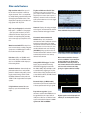
Other useful features
High resolution mode. Offers up to 12
bits of vertical resolution in real-time,
single-shot mode. This is accomplished
by serially filtering sequential data points
and mapping the filtered results to the
display when operating at time base settings greater than 10-μs/div.
Help is at your fingertips. An embedded
help system – available in 11 languages
– gives you quick answers if you don’t
understand a feature. Simply press and
hold the corresponding front-panel key,
and a screen pops up to explain its function.
Waveform math with FFT. Analysis functions include subtract, multiply, integrate,
square root, and differentiate, as well as
fast Fourier transforms (FFT).
Peak detect. 250 ps on 500-MHz and 1GHz models, 500 ps on 350-MHz models
and 1 ns on 100-MHz models helps you
find narrow glitches.
AutoProbe interface. Automatically sets
probe attenuation factors and provides
power for selected active probes, including the award-winning 1130A 1.5-GHz
InfiniiMax differential active probe and
1156A 1.5-GHz single-ended active probe
systems.
5-digit hardware counter. Measures
frequency up to the bandwidth of the
scope.
Trig Out and Reference Clock In/Out.
Provides an easy way to synchronize
your scope to other instruments. Use the
Trig Out port to connect your scope to a
frequency counter for more accurate frequency measurements or to cross trigger
other instruments.
Autoscale. Displays all analog and digital
active signals, and automatically sets the
vertical, horizontal and trigger controls.
23 automatic measurements with
statistics Get up to 4 simultaneous
measurements with 5 additional statistics
beyond the current value. Fast update
rate provides statistical data for enabled
measurements such as mean, min, max,
standard deviation and count. Pressing
[QuickMeas] brings up the last four automated measurements selected. Cursors
automatically track the most recently
selected measurement.
Analog HDTV/EDTV trigger. The 6000
Series comes standard with analog
HDTV/EDTV triggering for standards
like 1080i, 1080p, 720p and 480p as well
as standard video triggering on any line
within a field, all lines, all fields and odd
or even fields for NTSC, SECAM, PAL and
PAL-M video signals.
Press and hold a key for instant help.
Measurement statistics allow you
to have confidence in your measurements. Statistics can show that a
measurement is not only correct at
one moment, but that it has stabilized
and has a low variance over time,
giving it a higher statistical validity.
Bus mode display (on MSO models).
Quick and easy read-out of hexadecimal
or binary representation of logic signals.
Easy software upgrades. System
software is stored in flash ROM that can
be upgraded from the scope’s built-in
USB port or LAN. You can find the latest
system and IntuiLink software at: www.
Digital signals can be displayed individually or as overlayed bus values.
agilent.com/find/mso6000sw
5
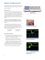
Why does a fast update rate matter?
While bandwidth, sample rate and memory depth are key criteria
for deciding which scope to purchase, an equally important characteristic is update rate.
What is update rate?
Update rate is how many waveforms acquisitions per seconds
you scope can acquire, process, and display. Oscilloscope “deadtime” is the time it takes for a scope to process and then display
an acquired waveform before re-arming it’s triggering for the next
acquisition. For traditional scopes, this time is often orders of
magnitude greater than acquisition time on fast time-per-division
settings.
If a glitch occurs during the scope’s dead-time, it won’t be
captured. The key to improving the probability of capturing a
signal anomaly during the scope acquisition time is to minimize
dead-time.
Oscilloscope vendors usually specify what their scope’s “bestcase” waveform update rates are. Some scope architectures
suffer from factors that can seriously degrade the “best-case”
update rates spec. Agilent’s 6000 Series architecture delivers the
world’s fastest update rate when using:
• Analog channels
• Analog and digital
• Deep memory
• Serial decode
Improves instrument responsiveness
Why is update rate important?
1.
Responsiveness. If you rotate the timebase control, you expect the oscilloscope to respond immediately – not seconds
later after the scope finishes processing data.
2.
Signal detail. Fast waveform update rates improve the
display quality of the waveform that you see on screen.
3.
Improves scope display quality
Certainty. Fast waveform update rates improve the scope’s
probability of capturing random and infrequent events.
Update rates directly affect a scope probability of capturing and
displaying infrequent and random events. Slow update rates will
cause a scope to miss subtle or infrequent signal details.
Improves probability of capturing
infrequent events
6
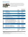
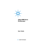
How update rate affects signal visibility
Capturing random and infrequent events on an oscilloscope is all about statistical probabilities. The key to improving the probability of capturing a signal anomaly is to minimize dead-time and take more pictures of the signal in a given timeframe. Here is
an example with Tek and Agilent scopes both connected to a target with a glitch that occurs 25 times per second.
?
?
Infrequent
signal activity
Critical
?
signal jitter
Tek MSO4104
Agilent MSO6104A
• Product data sheet: 50,000 waveforms per second.
• Product data sheet: 100,000 waveforms per second.
• Update rate = 18 waveforms per second with
10 Mpts and digital channels turned on. Resulting
measurement shown.
• Update rate = 95,000 waveforms per second with auto
memory and digital channels turned on. Resulting
measurement shown.
• Probability of capturing the infrequent glitch = 0.09%
after running for 10 seconds.
• Probability of capturing the infrequent glitch = 99%
after
running for 10 seconds.
• Average time to capture just one glitch = 128 minutes.
• Average time to capture just one glitch = 1.5 seconds.
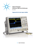
Memory*
Scope settings
Digital Channels
Measured update rates
Tek
Timebase setting
TEK MSO4104A**
LeCroy WR 104Xi Agilent MSO6104A
Initial setup
10 Kpts
20 ns/div
-
Serial Decode
-
55,000
27
95,000
Change timebase
10 Kpts
10 ns/div
-
-
2,700
27
95,000
Add digital channels
10 Kpts
20 ns/div
On
-
125
27
95,000
Increase memory setting
10 Mpts
20 ns/div
On
-
35
27
95,000
Turn on serial decode
10 Mpts
20 ns/div
On
On
0.2
25
95,000
* Agilent and LeCroy memory depth selection was automatically selected. Memory depth = display window times sample rate with up to 8 Mpts for Agilent.
** Tek measurements taken with version 2.13 firmware.
Seeing subtle signal detail and infrequent events requires a scope with fast waveform update rates. Don’t take a scope vendor’s
banner waveform update rate specification at face value. Test it yourself. It’s actually pretty easy to characterize a scope’s
update rate. Run a moderately fast signal (e.g. 50 Mhz) into a scope channel. Measure the scope’s average trigger output signal
frequency. This is your scope’s update rate for the specified timebase setting. Test the update rate of the scope under various
setup conditions. Setup conditions that Agilent suggests varying include timebase range, memory depth, and number of channels, including analog, digital, as well as channels assigned for serial decoding.
7
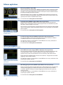
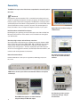
Software applications
Mask testing (N5455A or Option LMT)
Agilent’s mask test option (Option LMT or N5455A) for InfiniiVision Series oscilloscopes provides
a fast and easy way to test your signals to specified standards, and uncover unexpected signal
anomalies, such as glitches. Mask testing on other oscilloscopes is based on software-intensive
processing technology, which tends to be slow.
Agilent’s InfiniiVision scopes can perform up to 100,000 real-time waveform pass/fail tests per
second. This provides testing throughput significantly faster than other mask test solutions, making valid pass/fail statistics available almost instantly.
Mask testing uncovers an infrequent signal anomaly.
For more information: www.agilent.com/find/masktest
Segmented memory (N5454A or Option SGM on new scope purchases)
Segmented memory optimizes available memory for data streams that have long dead times
between activity. The application excels at analyzing signal activity associated with laser pulses,
serial buses, and bursty signals such as radar.
View an overlay of all signal segments, including MSO channels and serial decode, while highlighting the current segment. Quickly move between segments to view signal detail associated with a
specific segment.
For more information: www.agilent.com/find/segmented
Use segmented memory to optimize
available memory.
I2C/SPI serial trigger and decode (N5423A or Option LSS on new scope purchases)
This application displays real-time time-aligned decode of I2C and SPI serial buses. Hardwareaccelerated decode means the scope stays responsive and fast.
This application requires a 4-channel DSO or 4-channel MSO and can use any combination of
the scope or logic acquisition channels.
For more information: www.agilent.com/find/I2C-SPI
View on-screen serial decode of an I2C packet.
RS-232/UART serial decode and trigger (N5457A or Option 232 on new scope purchases)
Does your design include RS-232 or another type of UART? This application eliminates the need
to manually decode bus traffic. Using data captured on the scope or logic channels, the
application lets you easily view the information sent over a RS-232 or other UART serial bus.
Display real-time time-aligned decode of transmit and receive lines. The application also enables
triggering on RS-232/UART conditions.
Trigger on and decode RS-232/UART
transmission.
This application requires a 4-channel DSO or 4-channel MSO and can use any combination of the
scope or logic acquisition channels.
For more information: www.agilent.com/find/RS-232
CAN/LIN triggering and decode (N5424A or Option AMS on new scope purchases)
Trigger on and decode serially transmitted data based on CAN and LIN protocols. This application
not only provides triggering on complex serial signals, but it also provides unique hardwareaccelerated capabilities. Hardware-accelerated triggering and decode means the scope stays
responsive and fast.
This application requires a 4-channel DSO or 4-channel MSO and can use any combination of
scope or logic acquisition channels.
For more information: www.agilent.com/find/CAN-LIN.
Trigger on and decode CAN serial packets.
8
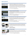
Software applications
FlexRay Measurements (N5432C or Option FLX on new scope purchases)
Trigger on and time-correlate FlexRay communication with physical layer signals. With
Agilent’s unique hardware-accelerated decoding, it provides the fastest decode update
rates in the industry while the scope remains responsive and fast. Also included with this
option is FlexRay eye-diagram mask testing and physical layer conformance test solution.
This application requires a 4-channel DSO or 4-channel MSO and can use any combination of scope or logic acquisition channels.
Time-correlated display of the FlexRay
physical layer signal with protocol
decoding.
For more information: www.agilent/find/flexray
I2S triggering and decode (Option SND or N5468A)
Find and debug intermittent errors and signal integrity problems faster on I2S audio protocol
devices. This application offers powerful triggering and our unique hardware-accelerated
decode and lister window so you can more easily find errors you could miss using other
serial bus decode tools.
This application requires a 4-channel DSO or 4-channel MSO and can use any
combination of scope or logic acquisition channels.
For more information: www.agilent.com/find/I2S
On-screen serial decode of an SPI packet
MIL-STD 1553 Serial Trigger and Decode (N5469A or Option 553 on new scope purchase)
This application provides integrated MIL-STD 1553 serial bus triggering, hardware-based
decoding, and eye-diagram mask testing to help you debug and characterize the
electrical/physical layer of MIL-STD 1553 serial buses faster than with traditional
“bit-counting” methods.
This application requires a 4-channel DSO or 4-channel MSO and can use any combination of scope of logic acquisition channels
Time-correlated display of the MIL-STD 1553
physical layer signal with protocol decoding.
For more information: www.agilent.com/find/1553
FPGA dynamic probe application (N5406A for Xilinx, N5434A for Altera)
Give your MSO internal FPGA visibility. Agilent’s MSO FPGA dynamic probe provides internal
FPGA visibility and quick instrument setup using an innovative core-assisted debug approach.
Measurement tasks that previously took hours can be done in a few mouse clicks. In a few
seconds, easily measure a different set of internal signals without changing your FPGA design.
For more information:
www.agilent.com/find/7000-altera
Debug and validate your FPGA designs
faster and more effectively
www.agilent.com/find/7000-xilinx
Power application (U1881A)
Need to make power measurements with your scope? Agilent’s power application provides a
full suite of power measurements that run on a PC connected to an InfiniiVision 7000B Series
oscilloscope. Make more accurate power supply efficiency measurements by using an U1880A
deskew fixture to deskew your voltage and current probes.
For more information: www.agilent.com/find/power-app
Use your scope to quickly make and
analyze power measurements.
9
Software applications and other accessories
Vector signal analysis software (89601A)
Expand the capability of your
scope with 89601A vector analysis
software.
Expand the measurement capability of your scope with the 89601A vector signal analysis software.
This advanced DSP-based software takes the digitized signal data provided by the scope and provides
FFT-based spectrum analysis and wide bandwidth digital modulation analysis for wireless communication signals like WCDMA and cdma2000, and wireless networking signals like 802.11 WiFi and 802.16
WiMaxTM.
Take advantage of the super wide bandwidth of your scope to capture and evaluate radar signals.
For more information: www.agilent.com/find/7000-vsa
Offline viewing and analysis (B4610A)
Need to view and analyze scope data away from your scope? Need to share measurement data with
geographically dispersed team members? Save your scope data to a USB or network drive and import
the data into a PC-based offline viewer. Pan and zoom.
View and analyze previously
acquired scope data on a PC-based
offline tool.
Use searching and filtering to gain insight on analog and digital buses. Email the data to team members who can use the same tool at their PCs.
For more information: www.agilent.com/find/InfiniiVisionOffline
Secure environment mode (Option SEC)
Option SEC – secure environment mode provides the highest level of security by ensuring internal nonvolatile memory is clear of all setup and trace settings in compliance with National Industrial Security
Program Operation Manual (NISPOM) Chapter 8 requirements. When this option is installed, it will
store setup and trace settings to internal volatile memory only.
Secure environment mode ensures
nonvolatile memory is cleared on
power off.
Volatile memory will be cleared during the power off cycle of the instrument. So you can move the
instrument out of a secure area with confidence.
For more information: Option SEC Secure
Environment Mode Option for Agilent 7000B Series Oscilloscopes Data Sheet
Evaluation kit (N2918A)
The evaluation kit includes a variety of signals that demonstrate MegaZoom III technology with its
fast deep memory, superior waveform update rate, high definition display and mixed analog, digital and
serial abilities.
The evaluation kit helps you discover
the power of InfiniiVision 7000B Series
oscilloscopes.
Using this scope evaluation kit along with the easy-to-follow user’s guide, you can quickly
become familiar with how to effectively operate an InfiniiVision 7000B Series scopes.
Battery power option (Option BAT – factory installed)
Agilent 6000 Series oscilloscopes provide an optional internal rechargeable lithium ion
battery that will enable 2+ hours without line power. Specifically designed for applications where line power is not available or where you need to take your scope with you
but you need more power than a handheld scopemeter provides. New oscilloscopes
equipped with this option can also be operated off of the N5429A 12-V automotive
adapter. The Agilent 6000 Series oscilloscopes offer the only high-performance scope
with battery option on the market.
For more information: www.agilent.com/find/6000_BAT
10
Probes and accessories
Agilent offers a complete family of innovative passive and active probes for the
InfiniiVision 6000 Series scopes to get your job done easily and accurately. Choosing
the correct probe for your application will help to ensure you are acquiring the signals
you expect. Below is a general guide on how to choose the type of probe. For the
most up-to-date information about Agilent’s accessories, please visit our Web site
at www.agilent.com/find/scope_probes.
Probe type
Key characteristics
DSO601xA,
MSO601xA
DSO603xA, MSO603xA
DSO605xA, MSO605xA
DSO610xA, MSO610xA
Passive probes: most common type of probe, rugged and economical with bandwidth generally lower than 600 MHz
10070C
10073C
10074C
1:1 20 MHz with probe ID
10:1 500 MHz with probe ID
10:1 150 MHz with probe ID
Recommended*
Compatible*
Included*
Recommended
Included
Compatible
High voltage passive probe: view up to 30 kVDC + peak AC voltage referenced to earth ground
10076A
N2771A
100:1, 4 kV, 250 MHz probe with ID
1000:1, 30 kV, 50 MHz probe
Recommended
Recommended
Recommended
Recommended
Single-ended active probes: contains small, active amplifier and enables the probe input capacitance to be very low resulting in high input
impedance on high frequencies. Least intrusive of all probes.
1156A
1144A
1145A
1.5 GHz AutoProbe interface
800 MHz (requires 1142A – power supply)
750 MHz 2-ch (requires 1142A – power supply)
Incompatible*
Incompatible
Incompatible
Recommended
Recommended
Recommended
Active differential probes: use to look at signals that are referenced to each others instead of earth ground and to look at small signals in
the presence of large DC offsets or other common mode signals such as power line noise.
1130A
N2772A
1141A
N2790A
N2791A
N2792A
N2793A
1.5 GHz InfiniiMax amplifier with AutoProbe interface (requires one or
more InfiniiMax probe head – E2675A, E2668A, E2669A)
20 MHz, 1.2 kVDC + peak AC max (requires N2773A power supply)
200 MHz, 200 VDC + peak AC max (requires 1142A power supply)
100 MHz, 1.4 kV high-voltage differential probe with AutoProbe interface
25 MHz, 700 V high-voltage differential probe (battery or USB powered)
200 MHz, +/-20 V differential probe (battery or USB powered)
800 MHz, +/-15 V differential probe (battery or USB powered)
Incompatible
Recommended
Recommended
Compatible
Incompatible
Recommended
Recommended
Recommended
Recommended
Recommended
Recommended
Recommended
Recommended
Recommended
Current probes: sense the AC or DC current flowing through a conductor and convert it to a voltage that can be viewed and measured on
an oscilloscope. Compatible with 1 MΩ scope input.
1146A
1147A
N2780A
N2781A
N2782A
N2783A
100 kHz, 100 A, AC/DC
50 MHz, 30 A, AC/DC with AutoProbe interface
2 MHz, 500 A, AC/DC (use with N2779A power supply)
10 MHz, 150 A, AC/DC (use with N2779A power supply)
50 MHz, 30 A, AC/DC (use with N2779A power supply)
100 MHz, 30 A, AC/DC (use with N2779A power supply)
Recommended
Incompatible
Recommended
Recommended
Recommended
Recommended
Recommended
Recommended
Recommended
Recommended
Recommended
Recommended
MSO probes: offer the best performance and access to the industry’s broad range of logic analyzer probing accessories
01650-61607** 40-pin, 16-channel logic probe
54620-68701
*
**
Logic probe with 2x8 flying leads (includes 20 IC clips and five
ground leads)
Recommended with
MSO6000 models
Recommended and
included with
MSO6000
models
Recommended with
MSO6000 models
Recommended and
included with MSO6000
models
Recommended is a suggestion from Agilent scope and probing experts that this probe works well with this scope.
Compatible indicates that the probe and scope will work together but that there are other choices that will work better.
Included means that this probe ships with this scope.
Incompatible is a warning that the probe will not work with the indicated scope.
With the addition of 40-pin logic cable, the Agilent MSO accepts numerous logic analyzer accessories such as Mictor, Samtec, flying leads or soft touch connectorless probe.
For more comprehensive information, refer to the Agilent InfiniiVision Series Oscilloscopes Probes and Accessories Data Sheet and Selection Guide (Agilent
publication numbers 5968-8153EN and 5989-6162EN).
11
Connectivity
The 6000 Series scopes come with the most comprehensive connectivity tools in
their class.
LXI class C
LAN eXtensions for Instrumentation (LXI) is a standards-based architecture for test
systems. By specifying the interaction of system components, LXI enables fast and efficient test system creation and reconfiguration. The 6000 Series oscilloscopes follow
specified LAN protocols and adhere to LXI requirements such as a built-in Web control
server, IVI-COM driver, and easy-to-use SCPI commands. The standard Agilent I/O
Library Suite makes it easy to configure and integrate instruments in your system.
IntuiLink toolbars and IntuiLink Data Capture
IntuiLink gives you a quick way to move oscilloscope screen shots and data into
Microsoft® Word and Excel. These toolbars can be installed from www.agilent.
Agilent Remote Front Panel running in
a Web browser
com/find/intuilink.
View Scope logic analyzer and oscilloscope correlation
View Scope enables simple and free time-correlated measurements between a 6000
Series oscilloscope and an Agilent 16900, 16800, 1690, or 1680 Series logic analyzer.
Scope and logic waveforms are integrated into a single logic analyzer waveform
display for easy viewing analysis – all with a simple point-to-point LAN connection.
You can also cross-trigger the instruments, automatically de-skew the waveforms, and
maintain marker tracking between the instruments.
National Instrument drivers
InfiniiVision 6000 Series oscilloscopes are supported by LabVIEW plug-and-play and
Use IntuiLink to import scope screen
shots and data into Microsoft Word
and Excel.
IVI-C drivers.
6000L Series, the most space efficient and affordable LXI Class C compliant
oscilloscope.
12
View 6000 Series signals on an external monitor
using the always-on XGA video output.
Use ViewScope to time-correlate
oscilloscope and logic analyzer
measurements.
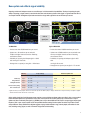
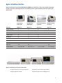
Agilent InfiniiVision Portfolio
Agilent’s InfiniiVision lineup includes 5000, 6000 and 7000B Series oscilloscopes. These share a number of advanced
hardware and software technology blocks. Use the following selection guide to determine which best matches your
specific needs.
Bandwidth
Largest display,
shallow depth
Optional battery,
100 MHz MSO
Ideal for ATE rackmount
applications
Smallest form factor,
lowest price
7000B Series
6000A Series
6000L Series
5000 Series
100 MHz Bandwidth
●
●
●
●
300/350 MHz Bandwidth
●
●
●
●
500 MHz Bandwidth
●
●
●
●
1 GHz Bandwidth
●
●
●
MSO Models
●
●
●
●
●
●
5U
1U
5U
GPIB Connectivity
Rackmount height
7U
Battery option
●
Display size
12.1”
6.3”
6.3”
Footprint (WxHxD)
17.9”x 10.9”x 6.8”
15.7”x 7.4”x 11.1”
17.1”x 1.7”x 10.6”
15.2”x 7.4”x 6.9”
Agilent’s InfiniiVision oscilloscope portfolio offers:
• A variety of form factors to fit your environment
• Responsive controls and best signal visibility
• Insightful application software
• Responsive deep memory with MegaZoom III
13
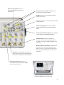
Agilent InfiniiVision 6000 Series oscilloscopes:
The fastest way to debug your analog, digital and serial designs
High-resolution color display with XGA resolution and 256
levels of intensity reveals subtle details that other scopes
won’t show you.
Built-in USB port makes it easy to save your work and
update your system software quickly.
Intensity knob allows you to see the right level of waveform
detail, just like an analog scope.
Free IntuiLink data capture PC software makes
transferring waveform data or screen image to a PC fast
and easy. Built-in web viewer via LAN allows for remote
measurements and viewing.
Built-in help in eleven languages – Simply press and
hold the front-panel key of interest for a few seconds,
and a help screen pops up to explain its function.
An XGA video output port allows you to
connect to a large external monitor.
Standard USB, LAN and GPIB ports
provide PC and printer connectivity.
Rear panel inputs/outputs
Trig Out port provides an easy way to synchronize
your scope to other instruments.
14
Built-in 10-MHz reference in/out port lets you synchronize
multiple measurement instruments in a system.
Built-in storage compartment allows you to
store probes and power cord for easy access
and transportation.
Quickly pan and zoom for analysis with MegaZoom III’s
instant response and optimum resolution.
QuickMeas shows up to four automated measurements
with the push of a button.
Save screen images to a connected USB storage device with
automated file names.
Standard serial triggering includes I2C, SPI, and USB
(optional CAN/LIN, and RS-232 advanced triggering and
decode).
Standard analog HDTV/EDTV triggering supports triggering
on 1080i, 1080p, 720p, 480p HDTV/EDTV standards.
AutoProbe interface automatically configures the
attenuation ratio of the probe and provides probe power
for Agilent’s active probes (available on 300 MHz to 1 GHz
models only).
Maximum sample rate and resolution is achieved on every
measurement. The scope automatically adjusts memory
depth as you use it, so you get maximum sample rate and
resolution on every measurement. You don’t even have to
think about it.
Autoscale lets you quickly display any active signals,
automatically setting the vertical, horizontal and trigger
controls for the best display, while optimizing memory.
Dedicated front-panel controls make it easy to
access the most common scope controls, including
vertical and horizontal scaling.
InfiniiVision 6000 Series 2-channel model
15
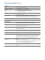
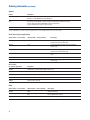
Performance characteristics
Acquisition: scope channels
Sample rate
MSO/DSO601xA/603xA: 2 GSa/sec each channel
MSO/DSO605xA/610xA: 4 GSa/sec half channel*, 2 GSa/sec each channel
Equivalent-time sample rate: 400 GSa/s (when real-time mode is turned off)
Memory depth
2 channels/4 channels
8 Mpts/4 Mpts
Vertical resolution
8 bits
Peak detection
MSO/DSO601xA: 1-ns peak detect
MSO/DSO603xA: 500-ps peak detect
MSO/DSO605xA/610xA: 250-ps peak detect
Averaging
Selectable from 2, 4, 8, 16, 32, 64 … to 65536
High resolution mode
Average mode with avg = 1
12 bits of resolution when ≥10 µs/div @ 4 GSa/s or ≥20-µs/div @ 2 GSa/s
Filter
Sinx/x interpolation (single shot BW = sample rate/4 or bandwidth of scope,
whichever is less) with vectors on and in real-time mode
Acquisition: digital channels (MSO6000A or MSO-upgraded DSO6000A only)
Sample rate
2 GSa/sec one pod**, 1 GSa/sec each pod
Maximum input frequency
250 MHz
Memory depth
One pod/both pods (with scope channels turned off)
8 Mpts/4 Mpts
One pod/both pods (with scope channels turned on)
2.5 Mpts/ 1.25 Mpts
Vertical resolution
1 bit
Glitch detection
2 ns (min pulse width)
* Half channel is when only one of channel 1 or 2 is turned on, and only channel 3 or 4 is turned on.
** A pod is a group of eight digital channels, either 0-7 or 8-15.
16
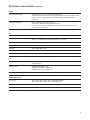
Performance characteristics (continued)
Vertical system: scope channels
Scope channels
MSO/DSO6xx2A: Ch 1 and 2 simultaneous acquisition
MSO/DSO6xx4A: Ch 1, 2, 3 and 4 simultaneous acquisition
Bandwidth (–3dB)*
MSO/DSO601xA: DC to 100 MHz
MSO/DSO603xA: DC to 300 MHz
MSO/DSO605xA: DC to 500 MHz
MSO/DSO610xA: DC to 1 GHz
AC coupled
MSO/DSO601xA: 3.5 Hz to 100 MHz
MSO/DSO603xA: 3.5 Hz to 300 MHz
MSO/DSO605xA: 3.5 Hz to 500 MHz
MSO/DSO610xA: 3.5 Hz to 1 GHz
Calculated rise time (=0.35/bandwidth)
MSO/DSO601xA: 3.5 nsec
MSO/DSO603xA: 1.17 nsec
MSO/DSO605xA: 700 psec
MSO/DSO610xA: 350 psec
Single-shot bandwidth
MSO/DSO601xA: 100 MHz
MSO/DSO603xA: 300 MHz
MSO/DSO605xA: 500 MHz
MSO/DSO610xA: 1 GHz (in half-channel mode)
Range1
MSO/DSO601xA: 1 mV/div to 5 V/div (1 MΩ)
MSO/DSO603xA and MSO/DSO605xA: 2 mV/div to 5 V/div (1 MΩ or 50 Ω)
MSO/DSO610xA: 2 mV/div to 5 V/div (1 MΩ), 2 mV/div to 1 V/div (50 Ω)
Maximum input
CAT I 300 Vrms, 400 Vpk; transient overvoltage 1.6 kVpk
CAT II 100 Vrms, 400 Vpk
With 10073C or 10074C 10:1 probe: CAT I 500 Vpk, CAT II 400 Vpk
Offset range
±5 V on ranges <10 mV/div; ±20 V on ranges 10 mV/div to 200 mV/div;
±75 V on ranges >200 mV/div
Dynamic range
±8 div
Input impedance
MSO/DSO601xA: 1 MΩ ± 1% || 11 pF
MSO/DSO603xA/605xA/610xA: 1 MΩ ± 1% || 14 pF or 50 Ω ± 1.5%, selectable
Coupling
AC, DC
BW limit
MSO/DSO601xA: 20 MHz selectable
MSO/DSO603xA/605xA/610xA: 25 MHz selectable
Channel-to-channel isolation
DC to max bandwidth >40 dB
Standard probes
MSO/DSO601xA: 10:1 10074C shipped standard for each scope channel
MSO/DSO603xA/605xA/610xA: 10:1 10073C shipped standard for each scope channel
Probe ID
MSO/DSO601xA: Auto probe sense
MSO/DSO603xA/605xA/610xA: Auto probe sense and AutoProbe interface
Agilent- and Tektronix-compatible passive probe sense
*
1
Denotes warranted specifications, all others are typical. Specifications are valid after a 30-minute warm-up period and ±10 °C from firmware calibration temperature.
1 mV/div is a magnification of 2 mV/div setting for 100 MHz models and 2 mV/div is a magnification of 4 mV/div setting for 300 MHz to 1 GHz models. For vertical accuracy
calculations, use full scale of 16 mV for 1 mV/div sensitivity setting and 32 mV for 2 mV/div sensitivity setting.
17
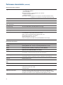
Performance characteristics (continued)
Vertical system: scope channels (continued)
ESD tolerance
±2 kV
Noise, RMS, input shorted
MSO/DSO601xA: 0.50% FS or 250 µV, whichever is greater
MSO/DSO603xA: 0.50% FS or 300 µV, whichever is greater
MSO/DSO605xA: 0.50% FS or 360 µV, whichever is greater
MSO/DSO610xA: 0.65% FS or 360 µV, whichever is greater
DC vertical gain accuracy*1
±2.0% full scale
DC vertical offset accuracy
≤200 mV/div: ±0.1 div ±2.0 mV ±0.5% offset value;
>200 mV/div: ±0.1 div ±2.0 mV ±1.5% offset value
Single cursor accuracy1
±{DC vertical gain accuracy + DC vertical offset accuracy + 0.2% full scale (~1/2 LSB)}
Example: for 50 mV signal, scope set to 10 mV/div (80 mV full scale), 5 mV offset,
accuracy = ±{2.0% (80 mV) + 0.1 (10 mV) + 2.0 mV + 0.5% (5 mV) + 0.2% (80 mV)} =
± 4.785 mV
Dual cursor accuracy*1
±{DC vertical gain accuracy + 0.4% full scale (~1 LSB)}
Example: for 50 mV signal, scope set to 10 mV/div (80 mV full scale), 5 mV offset,
accuracy = ±{2.0% (80 mV) + 0.4% (80 mV)} = ±1.92 mV
*
1
Denotes warranted specifications, all others are typical. Specifications are valid after a 30-minute warm-up period and ±10 °C from firmware calibration temperature.
1 mV/div is a magnification of 2 mV/div setting for 100 MHz models and 2 mV/div is a magnification of 4 mV/div setting for 300 MHz to 1 GHz models. For vertical accuracy
calculations, use full scale of 16 mV for 1 mV/div sensitivity setting and 32 mV for 2 mV/div sensitivity setting.
Vertical system: digital channels (MSO6000A or MSO-upgraded DSO6000A only)
Number of channels
16 logic timing channels – labeled D15 - D0
Threshold groupings
Pod 1: D7 - D0
Pod 2: D15 - D8
Threshold selections
TTL, CMOS, ECL and user-definable (selectable by pod)
User-defined threshold range
±8.0 V in 10 mV increments
Maximum input voltage
±40 V peak CAT I; transient overvoltage 800 Vpk
Threshold accuracy*
±(100 mV + 3% of threshold setting)
Input dynamic range
±10 V about threshold
Minimum input voltage swing
500 mV peak-to-peak
Input capacitance
~8 pF
Input resistance
100 kΩ ±2% at probe tip
Channel-to-channel skew
2 ns typical, 3 ns maximum
*
18
Denotes warranted specifications, all others are typical. Specifications are valid after a 30-minute warm-up period and ±10 °C from firmware calibration temperature.
Performance characteristics (continued)
Horizontal
Range
MSO/DSO601xA: 5 nsec/div to 50 sec/div
MSO/DSO603xA: 2 nsec/div to 50 sec/div
MSO/DSO605xA: 1 nsec/div to 50 sec/div
MSO/DSO610xA: 500 psec/div to 50 sec/div
Resolution
2.5 psec
Time scale accuracy*
≤ ± (15 + 2*(instrument age in years)) ppm
Vernier
1-2-5 increments when off, ~25 minor increments between major settings when on
Delay range
Pre-trigger (negative delay): Greater of 1 screen width or 1 ms (with 8 Mpts memory option)
Post-trigger (positive delay): 1 s to 500 seconds
Analog delta-t accuracy
Same channel: ±0.0015% reading ±0.1% screen width ±20 ps
Channel-to-channel: ±0.0015% reading ±0.1% screen width ±40 ps
Same channel example (MSO/DSO605xA):
For signal with pulse width of 10 µs, scope set to 5 µs/div (50 µs screen width),
delta-t accuracy = ±{0.0015% (10 µs) + 0.1% (50 µs) + 20 ps} = 50.17 ns
Logic delta-t accuracy
Same channel: ±0.005% reading ±0.1% screen width ±(1 logic sample period, 1 ns)
Channel-to-channel:
±0.005% reading ±0.1% screen width ±(1 logic sample period) ±chan-to-chan skew
Same channel example:
For signal with pulse width of 10 µs, scope set to 5 µs/div (50 µs screen width),
delta-t accuracy = ±{0.005% (10 µs) + 0.1% (50 µs) + 1 ns} = 51.5 ns
Modes
Main, delayed, roll, XY
XY
Bandwidth: Max bandwidth
Phase error @ 1 MHz: <0.5 degrees
Z Blanking: 1.4 V blanks trace (use external trigger on MSO/DSO6xx2A,
channel 4 on MSO/DSO6xx4A)
Reference positions
Left, center, right
Segmented memory rearm time
8 µs (minimum time between trigger events)
Trigger system
Sources
MSO6xx2A: Ch 1, 2, line, ext, D15 - D0
DSO6xx2A: Ch 1, 2, line, ext
MSO6xx4A: Ch 1, 2, 3, 4, line, ext, D15 - D0
DSO6xx4A: Ch 1, 2, 3, 4, line, ext
Modes
Auto, Normal (triggered), single
Holdoff time
~60 ns to 10 seconds
Trigger jitter
15 ps rms
*
Denotes warranted specifications for units manufactured after January 1, 2008. Specifications are valid after a 30 minute warm-up period and within 10 °C of firmware
calibration procedure.
19
Performance characteristics (continued)
Trigger system (continued)
Edge, pulse width, pattern, TV, duration, sequence, CAN, LIN, USB, I2C, SPI, RS-232,
Nth edge burst
Selections
20
Edge
Trigger on a rising, falling, alternating or either edge of any source
Pattern
Trigger at the beginning of a pattern of high, low, and don’t care levels and/or a rising or
falling edge established across any of the analog and digital channels, but only after a
pattern has stabilized for a minimum of 2 nsec.
The scope channel’s high or low level is defined by that channel’s trigger level. The logic
channel’s trigger level is defined by the threshold for the pod, 0 - 7 or 8 - 15.
Pulse width
Trigger when a positive- or negative-going pulse is less than, greater than, or within a
specified range on any of the source channels.
Minimum pulse width setting: 5 ns (MSO/DSO601xA/603xA scope channels)
2 ns (MSO/DSO605xA/610xA scope channels)
2 ns (logic channels on MSO6000A or
MSO-upgraded DSO6000A)
Maximum pulse width setting: 10 s
TV
Trigger using any scope channel on most analog progressive and interlaced video standards
including HDTV/EDTV, NTSC, PAL, PAL-M or SECAM broadcast standards. Select either
positive or negative sync pulse polarity. Modes supported include Field 1, Field 2, all fields,
all lines, or any line within a field. TV trigger sensitivity: 0.5 division of sync signal. Trigger
holdoff time can be adjusted in half field increments.
Sequence
Arm on event A, trigger on event B, with option to reset on event C or time delay.
CAN
Trigger on CAN (Controller Area Network) version 2.0A and 2.0B signals. Trigger on the start
of frame (SOF) bit (standard). N5424A option supports triggering on remote frame ID (RTR),
data frame ID (~RTR), remote or data frame ID, data frame ID and data, error frame, all errors,
acknowledge error and overload frame.
LIN
Trigger on LIN (Local Interconnect Network) sync break at beginning of message frame
(standard). N5424A option supports triggering on frame ID.
USB
Trigger on USB (Universal Serial Bus) start of packet, end of packet, reset complete, enter
suspend, or exit suspend on the differential USB data lines. USB low speed and full speed
are supported.
I2C
Trigger on I2C (Inter-IC bus) serial protocol at a start/stop condition or user defined frame
with address and/or data values. Also trigger on missing acknowledge, address with no acq,
restart, EEPROM read, and 10-bit write.
SPI
Trigger on SPI (Serial Protocol Interface) data pattern during a specific framing period.
Supports positive and negative Chip Select framing as well as clock Idle framing and
user-specified number of bits per frame.
RS-232/UART
This application eliminates the need to manually decode bus traffic. Using data captured on
the scope or digital channels, the application provides the ability to easily view the information
sent over a RS-232 serial bus. Display real-time time-aligned decode of transmit and receive
lines. This application also enables triggering on RS-232/UART conditions.
I2S
This application provides triggering on audio bus protocol channels for audio left, right,
either as well as =, ≠, >,< entered data values and within and out of range values. It provides
the ability to easily view the audio packets on the waveform and in a listing window.
Duration
Trigger on a multi-channel pattern whose time duration is less than a value, greater than a
value, greater than a time value with a timeout, or inside or outside of a set of time values.
Minimum duration setting: 2 ns
Maximum duration setting: 10 s
MIL-STD 1553
Trigger on specific Command/Status Words, Data Words, and error conditions.
FlexRay
Trigger on FlexRay Frames, errors, events and cycle-multiplexed triggering. N5432C or option
FLX supports also triggering on particular frame types symbolically, such as Startup frames,
Null frame, Sync frame, etc., as well as Boolean NOT frame types.
Performance characteristics (continued)
Trigger system (continued)
Nth edge burst
Trigger on the Nth edge of a burst that occurs after an idle time that you specify. Max edge
count: 65,536.
Autoscale
Finds and displays all active scope and logic (for MSO6000A series MSO) channels, sets edge
trigger mode on highest-numbered channel, sets vertical sensitivity on scope channels and
thresholds on logic channels, time base to display ~1.8 periods. Requires minimum voltage
>10 mVpp, 0.5% duty cycle and minimum frequency >50 Hz.
Scope channel triggering
Range (internal)
±6 div from center screen
Sensitivity*
<10 mV/div: greater of 1 div or 5 mV; ≥10 mV/div: 0.6 div
Coupling
AC (~3.5 Hz on MSO/DSO601xA, ~10 Hz on MSO/DSO603xA/605xA/610xA),
DC, noise reject, HF reject and LF reject (~50 kHz)
Digital (D15 - D0) channel triggering (MSO6000A or MSO-upgraded DSO6000A only)
Threshold range (user defined)
±8.0 V in 10 mV increments
Threshold accuracy
±(100 mV + 3% of threshold setting)
Predefined thresholds
TTL = 1.4 V, CMOS = 2.5 V, ECL = –1.3 V
External (EXT) triggering
MSO/DSO6xx2A (2-/2+16-ch models)
MSO/DSO6xx4A (4-/4+16-ch models)
Input impedance
MSO/DSO6012A: 1 MΩ ± 3% || 11 pF or 50 Ω
MSO/DSO6032A/6052A/6102A:
1 MΩ ± 3% || 14 pF or 50 Ω
MSO/DSO6014A: 1.015 kΩ ±5%
MSO/DSO6034A/6054A/6104A:
2.14 kΩ ±5%
Maximum input
CAT I 300 Vrms, 400 Vpk, CAT II 100 Vrms, 400 Vpk
±15 V
With 10073C 10:1 probe: CAT I 500 Vpk, CAT II 400 Vpk
5 Vrms with 50-Ω input
Range
DC coupling: trigger level ±1 V and ±8 V
±5 V
Sensitivity
For ±1 V range setting: DC to 100 MHz, 100 mV;
MSO/DSO6032A/6052A/6102A:
>100 MHz to bandwidth of oscilloscope: 200 mV
For ±8 V range setting: DC to 100 MHz, 250 mV;
MSO/DSO6032A/6052A/6102A:
>100 MHz to bandwidth of oscilloscope: 500 mV
MSO/DSO6014A:
DC to 100 MHz: 500 mV
MSO/DSO6034A/6054A/6104A:
DC to 500 MHz: 500 mV
Coupling
AC (~3.5 Hz), DC, noise reject, HF reject and LF reject (~50 kHz)
Probe ID
MSO/DSO601xA: Auto probe sense
MSO/DSO603xA/605xA/610xA: Auto probe sense and AutoProbe interface
Agilent- and Tektronix-compatible passive probe sense
*
Denotes warranted specifications, all others are typical. Specifications are valid after a 30-minute warm-up period and ±10 °C from firmware calibration temperature.
21
Performance characteristics (continued)
Display system
Display
6.3-inch (161 mm) diagonal color TFT LCD
Throughput of scope channels
Up to 100,000 waveforms/sec in real-time mode
Resolution
XGA – 768 vertical by 1024 horizontal points (screen area);
640 vertical by 1000 horizontal points (waveform area)
256 levels of intensity scale
Controls
Waveform intensity on front panel. Vectors on/off; infinite persistence on/off,
8 x 10 grid with intensity control
Built-in help system
Key-specific help displayed by pressing and holding key or softkey of interest.
Language support for 11 languages including English, German, French, Russian, Japanese,
Traditional Chinese, Simplified Chinese, Korean, Spanish, Portuguese and Italian.
Real-time clock
Time and date (user adjustable)
Measurement features
Automatic measurements
Measurements are continuously updated. Cursors track last selected measurement.
Up to four measurements can be displayed on screen at any one time.
Voltage (scope channels only)
Peak-to-peak, maximum, minimum, average, amplitude, top, base, overshoot, preshoot, RMS,
standard deviation (AC RMS), Ratio (dB)
Time
Frequency, period, + width, – width and duty cycle on any channel.
Rise time, fall time, X at max Y (time at max volts), X at min Y (time at min volts), delay, and
phase on scope channels only.
Counter
Built-in 5-digit frequency counter on any channel. Counts up to the scope’s bandwidth (1 GHz
max). The counter resolution can be increased to 8 digits with an external 10-MHz reference.
Threshold definition
Variable by percent and absolute value; 10%, 50%, 90% default for time measurements
Cursors
Manually or automatically placed readout of horizontal (X, ∆X, 1/∆X) and vertical (Y, ∆Y).
Tracking Cursors provides an additional mode for cursor positioning beyond the current
manual method. When cursor tracking is enabled, changing a cursor’s x-axis position
results in the y-axis cursor tracking the corresponding y-axis (voltage, current, etc.) value.
Additionally logic or scope channels can be displayed as binary or hex values.
Waveform math
f (g(t))
g(t): { 1, 2, 3, 4, 1-2, 1+2, 1x2, 3-4, 3+4, 3x4}
f(t): { 1-2, 1+2, 1x2, 3-4, 3+4, 3x4, FFT(g(t)), differentiate d/dt g(t), integrate ∫ g(t) dt, square
root √g(t) } Where 1,2,3,4 represent analog input channels 1, 2, 3, and 4
Note: Channels 3 and 4 only available on MSO/DSO6xx4A models
Measurement statistics
Statistical data for enabled measurements such as mean, min, max, standard deviation
and count
22
Performance characteristics (continued)
Storage
Save/recall (non-volatile)
10 setups and traces can be saved and recalled internally.
Optional secure environment mode ensures setups and traces are stored to internal volatile
memory so data is erased when power is removed. Compliant to NISPOM Chapter 8
requirements.
Storage type and format
USB 1.1 host ports on front and rear panels
Image formats: BMP (8-bit), BMP (24-bit), PNG (24-bit)
Data formats: X and Y (time/voltage) values in CSV format, ASCII XY and binary format
Trace/setup formats: Recalled
FFT
Points
Up to 10 kpts in precision mode
Source of FFT
1, 2, 1+2, 1-2, 1x2, MSO/DSO6xx4A: 3, 4, 3+4, 3-4, 3x4;
where 1, 2, 3, 4 represent the analog channel inputs 1, 2, 3, and 4
Window
Rectangular, flattop, hanning, Blackman Harris
Noise floor
–50 to –90 dB depending on averaging
Amplitude
Display in dBV, dBm at 50 Ω
Frequency resolution
0.05/time per div
Maximum frequency
50/time per div
I/O
Standard ports
USB 2.0 high speed device, two USB 1.1 host ports, 10/100-BaseT LAN, IEEE488.2 GPIB,
XGA video output
Max transfer rate
IEEE488.2 GPIB: 500 kbytes/sec
USB (USBTMC-USB488): 3.5 Mbytes/sec
100 Mbps LAN (TCP/IP): 1 Mbytes/sec
Supported printers via USB
For a list of currently supported printers visit www.agilent.com/find/InfiniiVision-printers
General characteristics
Physical size
35.4 cm wide x 18.8 cm high x 28.2 cm deep (without handle)
39.9 cm wide x 18.8 cm high x 28.2 cm deep (with handle)
Weight
Net: 4.9 kgs (10.8 lbs) Shipping: 9.4 kgs (20.7 lbs)
Probe comp output
Frequency ~1.2 kHz; Amplitude ~2.5 V
23
Performance characteristics (continued)
General characteristics (continued)
Trigger out
When Triggers is selected (delay ~17 ns)
0 to 5 V into high impedance
0 to 2.5 V into 50 Ω
When Source Frequency or Source Frequency/8* is selected
0 to 580 mV into high impedance
0 to 290 mV into 50 Ω
Max frequency output: 350 MHz (in source frequency mode when terminated in 50 Ω)
125 MHz (in source frequency/8 mode when terminated in 50 Ω)
10 MHz ref in/out
TTL out, 180 mV to 1 V amplitude with 0 to 2 V offset
Kensington lock
Connection on rear panel for security
Power requirements
Line voltage range
100-120 V, 50/60/400 Hz; 100-240V, 50/60 Hz auto ranging
Line frequency
50/60 Hz, 100-240 VAC; 400 Hz, 100-120 VAC
Power usage
120 W max
Battery option – BAT
100-240 V, 50/60 Hz
2+ hours between charges, battery-low indicator at 20%
Battery capacity after repeated charging: 80% after 300 cycles
Non-operating temperature: –20 °C to 60 °C
Operating temperature: 0 °C to 50 °C
Power consumption is 67-75 Watts with optional N5429A DC Power adapter
Environmental characteristics
Ambient temperature
Operating -10 °C to +55 °C; non-operating –40 °C to +70 °C
Humidity
Operating 95% RH at 40 °C for 24 hr; non-operating 90% RH at 65 °C for 24 hr
Altitude
Operating to 4,570 m (15,000 ft); non-operating to 15,244 m (50,000 ft)
Vibration
Agilent class B1 and MIL-PRF-28800F; class 3 random
Shock
Agilent class B1 and MIL-PRF-28800F; class 3 random; (operating 30g, 1/2 sine,
11 ms duration, 3 shocks/axis along major axis, total of 18 shocks)
Pollution degree
Normally only dry non-conductive pollution occurs.
Occasionally a temporary conductivity caused by condensation must be expected.
Indoor use
Rated for indoor use only
Other
Measurement categories
CAT I
Regulatory information
Safety IEC 61010-1:2001 / EN 61010-1:2001
Canada: CSA C22.2 No. 1010.1:1992
UL 61010B-1:2003
Supplementary information
*
24
The product herewith complies with the requirements of the Low Voltage Directive
73/23/EEC and the EMC Directive 89/336/EEC, and carries the CE-marking accordingly.
The product was tested in a typical configuration with HP/Agilent test systems.
Source Frequency/8 is supported on 300 MHz to 1 GHz 6000 Series only.
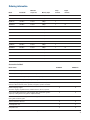
Ordering information
Model
Bandwidth
Maximum
sample rate
Memory depth
Scope
channels
DSO6012A
100 MHz
2 GSa/s
8 Mpts
2
MSO6012A
100 MHz
2 GSa/s
8 Mpts
2
DSO6014A
100 MHz
2 GSa/s
8 Mpts
4
MSO6014A
100 MHz
2 GSa/s
8 Mpts
4
DSO6032A
300 MHz
2 GSa/s
8 Mpts
2
MSO6032A
300 MHz
2 GSa/s
8 Mpts
2
DSO6034A
300 MHz
2 GSa/s
8 Mpts
4
MSO6034A
300 MHz
2 GSa/s
8 Mpts
4
DSO6052A
500 MHz
4 GSa/s
8 Mpts
2
MSO6052A
500 MHz
4 GSa/s
8 Mpts
2
DSO6054A
500 MHz
4 GSa/s
8 Mpts
4
MSO6054A
500 MHz
4 GSa/s
8 Mpts
4
DSO6102A
1 GHz
4 GSa/s
8 Mpts
2
MSO6102A
1 GHz
4 GSa/s
8 Mpts
2
DSO6104A
1 GHz
4 GSa/s
8 Mpts
4
MSO6104A
1 GHz
4 GSa/s
8 Mpts
4
Digital
channels
16
16
16
16
16
16
16
16
Accessories included:
Model number
DSO60xxA
MSO60xxA
Standard 3-year warranty
●
●
Standard 1-year warranty on MSO/DSO6000A-BAT option
●
●
10073C or 10074C 10:1 divider passive probe with readout per scope channel
●
●
16 channel flying lead set logic probe (two pods with eight channels each)
●
Built-in help language support for English, French, German, Russian, simplified
Chinese, traditional Chinese, Korean, Spanish, Portuguese, Japanese and Italian
●
●
Interface language support
GUI menus: English, simplified Chinese, traditional Chinese, Korean, Japanese
●
●
Choose one of ABA (printed users guide in English), ABJ (printed users guide in
Japanese) or AB2 (printed users guide in simplified Chinese)
●
●
Documentation CDs/PDFs of Programmer’s reference guide,
User’s guide and Service guide
●
●
Agilent I/O libraries suite 15.0
●
●
Localized power cord
●
●
Front panel cover
●
●
Note: IntuiLink Data Capture software available free on web at www.agilent.com/find/intuilink
25
Ordering information (continued)
Options
Product
Description
DSO to MSO upgrade*
N2914A* for DSO/MSO601xA, DSO/MSO603xA
N2915A* for DSO/MSO605xA, DSO/MSO610xA
SEC
Secure Environment Mode - Provides compliance with National Industrial Security
Program Operating Manual (NISPOM) Chapter 8 requirements
(factory-installed option only for new purchase)
A6J
ANSI Z540 compliant calibration
*Includes a 54620-68701 logic cable kit, a label and an upgrade license to activate the MSO features. Installs in less than 5 minutes.
Serial data analysis applications
Option number – user installed
Option number – factory installed
Description
N5424A
AMS
CAN/LIN automotive triggering and decode
N5423A
LSS
N5457A
232
N5468A
SND
I2S Triggering and Decode (4 and 4+16 channel models
only)
N5432C
FLX
FlexRay Measurements (4 and 4+16 channel models only)
N5469A
553
MIL-STD 1553 Triggering and Decode (4 and 4+16 channel
models only)
(4 and 4+16 channel models only)
I2C/SPI serial decode option (for 4/4+16 channel
models only)
RS-232/UART triggering and decode
(4 and 4+16 channel models only)
User installed
PC-assisted applications
Description
N5406A
FPGA dynamic probe for Xilinx (MSO models only)
N5434A
FPGA dynamic probe for Altera (MSO models only)
B4610A
Offline viewing and analysis of MSO/DSO data on a PC
U1881A
Power measurement and analysis application
E2690B
ASA’s Oscilloscope tools
Other
Option number – user installed
Option number – factory installed
Description
N5454A
SGM
Segmented memory
BAT
Re-chargeable battery option
LMT
Mask limit testing
N5455A
26
Ordering information (continued)
Accessories
Options
Description
N2916B
Rackmount kit for 6000 Series oscilloscope
N2917B
Transit case with foam molding customized for InfiniiVision 6000 Series
N2918A
InfiniiVision evaluation kit
1180CZ
Testmobile scope cart
N2919A
Testmobile bracket for 1180CZ and 6000
10833A
GPIB cable, 1 m long
N2916B rackmount kit
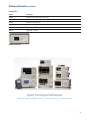
Agilent Technologies Oscilloscopes
Multiple form factors from 20 MHz to >90 GHz | Industry leading specs | Powerful applications
27
www.agilent.com
www.agilent.com/find/6000
Agilent Email Updates
www.agilent.com/find/emailupdates
Get the latest information on the products
and applications you select.
Agilent Direct
www.agilent.com/find/agilentdirect
Quickly choose and use your test
equipment solutions with confidence.
Remove all doubt
Our repair and calibration services will get
your equipment back to you, performing
like new, when promised. You will get
full value out of your Agilent equipment
throughout its lifetime. Your equipment
will be serviced by Agilent-trained
technicians using the latest factory
calibration procedures, automated repair
diagnostics and genuine parts. You will
always have the utmost confidence in your
measurements.
Agilent Channel Partners
www.agilent.com/find/channelpartners
Get the best of both worlds: Agilent’s
measurement expertise and product
breadth, combined with channel
partner convenience.
Agilent offers a wide range of additional
expert test and measurement services for
your equipment, including initial start-up
assistance, onsite education and training,
as well as design, system integration, and
project management.
For more information on repair and
calibration services, go to:
www.lxistandard.org
LXI is the LAN-based successor to GPIB,
providing faster, more efficient connectivity.
Agilent is a founding member of the LXI
consortium.
www.agilent.com/find/removealldoubt
For more information on Agilent Technologies’
products, applications or services, please
contact your local Agilent office. The
complete list is available at:
www.agilent.com/find/contactus
Americas
Canada
Latin America
United States
(877) 894-4414
305 269 7500
(800) 829-4444
Asia Pacific
Australia
China
Hong Kong
India
Japan
Korea
Malaysia
Singapore
Taiwan
Thailand
1 800 629 485
800 810 0189
800 938 693
1 800 112 929
0120 (421) 345
080 769 0800
1 800 888 848
1 800 375 8100
0800 047 866
1 800 226 008
Europe & Middle East
Austria
43 (0) 1 360 277
1571
Belgium
32 (0) 2 404 93 40
Denmark
45 70 13 15 15
Finland
358 (0) 10 855 2100
France
0825 010 700*
*0.125 €/minute
Germany
49 (0) 7031 464
6333
Ireland
1890 924 204
Israel
972-3-9288-504/544
Italy
39 02 92 60 8484
Netherlands
31 (0) 20 547 2111
Spain
34 (91) 631 3300
Sweden
0200-88 22 55
Switzerland
0800 80 53 53
United Kingdom 44 (0) 118 9276201
Other European Countries:
www.agilent.com/find/contactus
Product specifications and descriptions in
this document subject to change without
notice.
October 1, 2009
© Agilent Technologies, Inc. 2010
Printed in USA, February 28, 2010
5989-2000EN