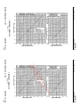
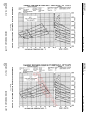
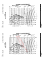
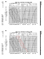
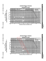
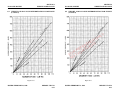
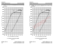
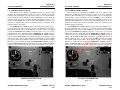
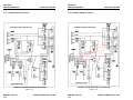
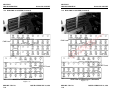
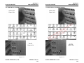
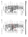
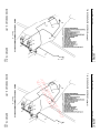
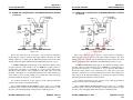
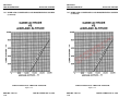
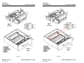
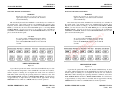
1
MALIBU MIRAGE
MALIBU MIRAGE
PA-46-350P
PA-46-350P
SN 4636196 AND UP
SN 4636196 AND UP
PILOT’S
OPERATING
HANDBOOK
PILOT’S
OPERATING
HANDBOOK
AND
Y
L
NAPPROVED
FAA
O
AIRPLANEEFLIGHT MANUAL
C
N
E HT
R
E LIG
F
E F
R
R
R
O
FO T F
NO
AND
FAA APPROVED
AIRPLANE FLIGHT MANUAL
AIRPLANE
SERIAL NO. ___________________________
AIRPLANE
REGIST. NO. _______________________
PA-46-350P
REPORT: VB-1710 FAA APPROVED BY:
DATE OF APPROVAL:
FEBRUARY 23, 1999
AIRPLANE
SERIAL NO. ___________________________
AIRPLANE
REGIST. NO. _______________________
PA-46-350P
REPORT: VB-1710 FAA APPROVED BY:
PETER E. PECK
D.O.A. NO. SO-1
THE NEW PIPER AIRCRAFT, INC.
VERO BEACH, FLORIDA
DATE OF APPROVAL:
FEBRUARY 23, 1999
THIS HANDBOOK INCLUDES THE MATERIAL REQUIRED TO BE FURNISHED TO THE
PILOT BY THE FEDERAL AVIATION REGULATIONS AND ADDITIONAL INFORMATION
PROVIDED BY THE MANUFACTURER AND CONSTITUTES THE FAA APPROVED
AIRPLANE FLIGHT MANUAL. THIS HANDBOOK MUST BE CARRIED IN THE
AIRPLANE AT ALL TIMES.
TM
PETER E. PECK
D.O.A. NO. SO-1
THE NEW PIPER AIRCRAFT, INC.
VERO BEACH, FLORIDA
THIS HANDBOOK INCLUDES THE MATERIAL REQUIRED TO BE FURNISHED TO THE
PILOT BY THE FEDERAL AVIATION REGULATIONS AND ADDITIONAL INFORMATION
PROVIDED BY THE MANUFACTURER AND CONSTITUTES THE FAA APPROVED
AIRPLANE FLIGHT MANUAL. THIS HANDBOOK MUST BE CARRIED IN THE
AIRPLANE AT ALL TIMES.
TM
WARNING
WARNING
EXTREME CARE MUST BE EXERCISED TO LIMIT THE
USE OF THIS HANDBOOK TO APPLICABLE AIRCRAFT.
T H I S H A N D - B O O K I S VA L I D F O R U S E W I T H T H E
AIRPLANE IDENTIFIED ON THE FACE OF THE TITLE
PAGE. SUBSEQUENT REVISIONS SUPPLIED BY PIPER
MUST BE PROPERLY INSERTED.
EXTREME CARE MUST BE EXERCISED TO LIMIT THE
USE OF THIS HANDBOOK TO APPLICABLE AIRCRAFT.
T H I S H A N D - B O O K I S VA L I D F O R U S E W I T H T H E
AIRPLANE IDENTIFIED ON THE FACE OF THE TITLE
PAGE. SUBSEQUENT REVISIONS SUPPLIED BY PIPER
MUST BE PROPERLY INSERTED.
Published by
PUBLICATIONS DEPARTMENT
Issued: FEBRUARY 23, 1999
Published by
PUBLICATIONS DEPARTMENT
Issued: FEBRUARY 23, 1999
© 1997 THE NEW PIPER AIRCRAFT, INC.
All Rights Reserved
© 1997 THE NEW PIPER AIRCRAFT, INC.
All Rights Reserved
REPORT: VB-1710
ii
ISSUED: FEBRUARY 23, 1999
Y
L
N
O
E
C
N
E HT
R
E LIG
F
E F
R
R
R
O
FO T F
NO
REPORT: VB-1710
ii
ISSUED: FEBRUARY 23, 1999
PA-46-350P, MALIBU
PA-46-350P, MALIBU
APPLICABILITY
APPLICABILITY
Application of this handbook is limited to the specific Piper PA-46-350P
model airplane designated by serial number and registration number on the
face of the title page of this handbook.
Application of this handbook is limited to the specific Piper PA-46-350P
model airplane designated by serial number and registration number on the
face of the title page of this handbook.
This handbook cannot be used for operational purposes unless kept in a
current status.
This handbook cannot be used for operational purposes unless kept in a
current status.
WARNING
WARNING
INSPECTION, MAINTENANCE AND PARTS REQUIREMENTS
FOR ALL NON-PIPER APPROVED STC INSTALLATIONS ARE
NOT INCLUDED IN THIS HANDBOOK. WHEN A NON-PIPER
APPROVED STC INSTALLATION IS INCORPORATED ON THE
AIRPLANE, THOSE PORTIONS OF THE AIRPLANE
AFFECTED BY THE INSTALLATION MUST BE INSPECTED IN
ACCORDANCE WITH THE INSPECTION PROGRAM
PUBLISHED BY THE OWNER OF THE STC. SINCE NON-PIPER
APPROVED STC INSTALLATIONS MAY CHANGE SYSTEMS
INTERFACE, OPERATING CHARACTERISTICS AND
COMPONENT LOADS OR STRESSES ON ADJACENT
STRUCTURES, PIPER PROVIDED INSPECTION CRITERIA
MAY NOT BE VALID FOR AIRPLANES WITH NON-PIPER
APPROVED STC INSTALLATIONS.
ISSUED: FEBRUARY 23, 1999
REVISED: OCTOBER 14, 2002
REPORT: VB-1710
iii
Y
L
N
O
E
C
N
E HT
R
E LIG
F
E F
R
R
R
O
FO T F
NO
ISSUED: FEBRUARY 23, 1999
REVISED: OCTOBER 14, 2002
REPORT: VB-1710
iii
PA-46-350P, MALIBU
PA-46-350P, MALIBU
REVISIONS
REVISIONS
The information compiled in the Pilot’s Operating Handbook, with the
exception of the equipment list, will be kept current by revisions distributed
to the airplane owners. The equipment list was current at the time the
airplane was licensed by the manufacturer and thereafter must be maintained
by the owner.
Revision material will consist of information necessary to update the
text of the present handbook and/or to add information to cover added
airplane equipment.
I.
I.
Revisions
Revisions will be distributed whenever necessary as complete page
replacements or additions and shall be inserted into the handbook in
accordance with the instructions given below:
1. Revision pages will replace only pages with the same page number.
2. Insert all additional pages in proper numerical order within each
section.
3. Insert page numbers followed by a small letter in direct sequence with
the same common numbered page.
II. Identification of Revised Material
Each handbook page is dated at the bottom of the page showing the date of
original issue and the date of the latest revision. Revised text and illustrations
are indicated by a black vertical line located along the outside margin of each
revised page opposite the revised, added, or deleted information. A vertical line
next to the page number indicates that an entire page has been changed or
added.
Vertical black lines indicate current revisions only. Correction of typographical
or grammatical errors or the physical relocation of information on a page will
not be indicated by a symbol.
Revisions
Revisions will be distributed whenever necessary as complete page
replacements or additions and shall be inserted into the handbook in
accordance with the instructions given below:
1. Revision pages will replace only pages with the same page number.
2. Insert all additional pages in proper numerical order within each
section.
3. Insert page numbers followed by a small letter in direct sequence with
the same common numbered page.
Y
L
N
O
E
C
N
E HT
II. Identification of Revised MaterialR
FatEthe Fbottom
LIG
Each handbook page is E
dated
of the page showing the date of
original issue and the date
of the latest revision. Revised text and illustrations
R
R
are indicated by a black
vertical
line located along the outside margin of each
R
O
O theTrevised,
revised page opposite
F added, or deleted information. A vertical line
next to the F
page number
indicates that an entire page has been changed or
O
added.
N
Vertical black lines indicate current revisions only. Correction of typographical
or grammatical errors or the physical relocation of information on a page will
not be indicated by a symbol.
ORIGINAL PAGES ISSUED
ORIGINAL PAGES ISSUED
The original pages issued for this handbook prior to revision are given
below:
The original pages issued for this handbook prior to revision are given
below:
Title, ii through viii, 1-1 through 1-12, 2-1 through 2-16, 3-1 through 3-38,
4-1 through 4-42, 5-1 through 5-34, 6-1 through 6-14, 7-1 through 7-64, 8-1
through 8-24, 9-1 through 9-114, and 10-1 through 10-2.
Title, ii through viii, 1-1 through 1-12, 2-1 through 2-16, 3-1 through 3-38,
4-1 through 4-42, 5-1 through 5-34, 6-1 through 6-14, 7-1 through 7-64, 8-1
through 8-24, 9-1 through 9-114, and 10-1 through 10-2.
REPORT: VB-1710
iv
REPORT: VB-1710
iv
ISSUED: FEBRUARY 23, 1999
REVISED: OCTOBER 14, 2002
ISSUED: FEBRUARY 23, 1999
REVISED: OCTOBER 14, 2002
PA-46-350P, MALIBU
PA-46-350P, MALIBU
PILOT'S OPERATING HANDBOOK LOG OF REVISIONS
PILOT'S OPERATING HANDBOOK LOG OF REVISIONS
Current Revisions to the PA-46-350P Malibu Pilot's Operating Handbook,
REPORT: VB-1710 issued FEBRUARY 23, 1999.
Revision
FAA Approved
Number and
Revised
Description of Revisions
Signature
Code
Pages
and Date
Rev. 1
v
Added Rev. 1 to L of R pg.
(PR990920)
3-11
Revised para. 3.3m
3-12
Revised para. 3.3m
3-32
Revised para. 3.27
3-35
Revised para. 3.43
4-13
Revised para. 4.5g
5-3
Revised para. 5.5
5-4
Revised para. 5.5
5-7
Revised para. 5.5
5-8
Revised para. 5.5
5-9
Revised List of Fig.’s
5-22
Revised Fig. 5.23
5-23
Revised Fig. 5.24
5-24
Revised Fig. 5.25
5-28
Revised Fig. 5.29
5-33
Revised Fig. 5.39
5-34
Revised Fig. 5.41
6-5
Revised para. 6.3
6-11
Revised para. 6.9
6-12
Revised para. 6.9
6-14
Revised Fig. 6.15
7-34
Revised para. 7.17
7-35
Revised para. 7.19
7-38
Revised para. 7.19
7-43
Revised para. 7.21
7-48
Revised para. 7.25
7-49
Revised para. 7.25
7-50
Revised para. 7.25
9-i
Revised TOC
9-10
Revised Section 4
9-24
Revised Section 7
9-87
Revised Title
ISSUED: FEBRUARY 23, 1999
REVISED: SEPTEMBER 20, 1999
ISSUED: FEBRUARY 23, 1999
REVISED: SEPTEMBER 20, 1999
REPORT: VB-1710
v
Y
L
N
O
E
C
N
E HT
R
E LIG
F
E F
R
R
R
O
FO T F
NO
REPORT: VB-1710
v
PA-46-350P, MALIBU
PA-46-350P, MALIBU
PILOT'S OPERATING HANDBOOK LOG OF REVISIONS (cont)
Revision
Number and
Code
Rev. 1
(continued)
Revised
Pages
9-115
thru
9-122
Description of Revisions
Added Section 9
Supplement 15
FAA Approved
Signature
and Date
PILOT'S OPERATING HANDBOOK LOG OF REVISIONS (cont)
Revision
Number and
Code
Rev. 1
(continued)
Revised
Pages
9-115
thru
9-122
Peter E. Peck
Description of Revisions
Added Section 9
Supplement 15
Rev. 3
(PR010910)
vi
2-14
9-ii
9-115
thru
9-122
9-123
9-124
Added Rev. 2 to L of R.
Revised para. 2.35.
Revised T of C.
Revised headers.
vi
vi-a
vi-b
2-16
3-9
3-28
6-4
7-14
7-15
7-29
9-ii
9-32
9-118
9-125
thru
9-132
Added Rev. 3 to L of R.
Added page and Rev. 3.
Added page.
Revised para. 2.35.
Revised para. 3.3k.
Revised para. 3.24.
Revised Fig. 6-3.
Revised para. 7.8.
Revised para. 7.8.
Revised para. 7.11.
Revised T of C.
Revised Section 4.
Revised Section 2.
Added pages
and Supplement 17.
REPORT: VB-1710
vi
Rev. 2
(PR991112)
Christina L. Marsh
Added page and Supp. 16.
Added page.
Nov. 12, 1999
Date
ISSUED: FEBRUARY 23, 1999
REVISED: SEPTEMBER 10, 2001
Peter E. Peck
Sept. 10, 1999
Date
Sept. 10, 1999
Date
Rev. 2
(PR991112)
FAA Approved
Signature
and Date
vi
2-14
9-ii
9-115
thru
9-122
9-123
9-124
Added Rev. 2 to L of R.
Revised para. 2.35.
Revised T of C.
Revised headers.
3-28
6-4
7-14
7-15
7-29
9-ii
9-32
9-118
9-125
thru
9-132
Revised para. 3.24.
Revised Fig. 6-3.
Revised para. 7.8.
Revised para. 7.8.
Revised para. 7.11.
Revised T of C.
Revised Section 4.
Revised Section 2.
Added pages
and Supplement 17.
Y
L
N
O
E
C Christina L. Marsh
Added page and N
Supp. 16.
T Nov. 12, 1999
Added page. E
H
R
Date
E LIG
F
E F
R
Rev. 3
viR
AddedR
Rev. 3 to L of R.
O
(PR010910) Ovi-a
Added
page and Rev. 3.
F vi-b T FAdded page.
O Revised para. 2.35.
N2-16
3-9
Revised para. 3.3k.
REPORT: VB-1710
vi
ISSUED: FEBRUARY 23, 1999
REVISED: SEPTEMBER 10, 2001
PA-46-350P, MALIBU
PA-46-350P, MALIBU
PILOT'S OPERATING HANDBOOK LOG OF REVISIONS (cont)
Revision
FAA Approved
Number and
Revised
Description of Revisions
Signature
Code
Pages
and Date
Rev. 3
9-133
Added pages
(PR010910)
thru
and Supplement 18.
continued
9-142
9-143
Added pages
thru
and Supplement 19.
9-150
9-151
Added pages
thru
and Supplement 20.
9-156
9-157
Added pages
Peter E. Peck
thru
and Supplement 21.
9-160
Sept. 10, 2001
Date
Rev. 4
(PR011220)
vi-a
9-116
Added Rev. 4 to L of R.
Revised Section 1.
Albert J. Mill
Dec. 20, 2001
Date
Rev. 5
(PR020415)
vi-a
2-16
Added Rev. 5 to L of R.
Revised para. 2.35.
Albert J. Mill
PILOT'S OPERATING HANDBOOK LOG OF REVISIONS (cont)
Revision
FAA Approved
Number and
Revised
Description of Revisions
Signature
Code
Pages
and Date
Rev. 3
9-133
Added pages
(PR010910)
thru
and Supplement 18.
continued
9-142
9-143
Added pages
thru
and Supplement 19.
9-150
9-151
Added pages
thru
and Supplement 20.
9-156
9-157
Added pages
Peter E. Peck
thru
and Supplement 21.
9-160
Sept. 10, 2001
Date
Y
L
N
O
E
C
N
T
ERev. 4H
R
Rev. 4
vi-a
Added
to L of R.
G 1.
E LISection
(PR011220)
9-116F Revised
E F
R
R
R
O
FO T F
N5O vi-a Added Rev. 5 to L of R.
Rev.
Albert J. Mill
(PR020415)
Albert J. Mill
2-16
Revised para. 2.35.
April 15, 2002
Date
April 15, 2002
Date
Rev. 6
(PR020419)
vi-a
9-ii
9-161
9-162
Added Rev. 6 to L of R.
Revised T of C.
Added pages
and Supplement 22.
ISSUED: FEBRUARY 23, 1999
REVISED: APRIL 19, 2002
Albert J. Mill
April 19, 2002
Date
REPORT: VB-1710
vi-a
Dec. 20, 2001
Date
Rev. 6
(PR020419)
vi-a
9-ii
9-161
9-162
Added Rev. 6 to L of R.
Revised T of C.
Added pages
and Supplement 22.
ISSUED: FEBRUARY 23, 1999
REVISED: APRIL 19, 2002
Albert J. Mill
April 19, 2002
Date
REPORT: VB-1710
vi-a
PA-46-350P, MALIBU
PA-46-350P, MALIBU
PILOT'S OPERATING HANDBOOK LOG OF REVISIONS (cont)
Revision
Number and
Code
Rev. 7
(PR021014)
Revised
Pages
iii
iv
vi-b
8-1
8-1A
8-1B
8-2
Rev. 8
(PR021108)
Rev. 9
(PR040120)
Description of Revisions
Added Warning and moved
info. to page iv.
Moved info. from page iii.
Added Rev. 7 to L of R.
Moved info. to page 8-1B
and revised para. 8.1.
Added page and
revised para. 8.1.
Added page and moved info.
from pages 8-1 and 8-2.
Moved info. to page 8-1B
and revised para. 8.3.
vi-b
9-ii
9-163
thru
9-164
Added Rev. 8 to L of R.
Revised T of C.
Added pages
and Supplement 23.
vi-b
4-i
thru
4-iv
4-1
thru
4-14
4-41
9-ii
9-165
thru
9-168
Added Rev. 9 to L of R.
Revised page headers.
REPORT: VB-1710
vi-b
FAA Approved
Signature
and Date
Revision
Number and
Code
Rev. 7
(PR021014)
Revised
Pages
iii
iv
vi-b
8-1
8-1A
8-1B
Albert. J. Mill
8-2
Oct. 14, 2002
Date
Albert J. Mill
Nov. 8, 2002
Date
Revised page headers.
Revised para. 4.50.
Revised T of C.
Added pages
and Supplement 24.
PILOT'S OPERATING HANDBOOK LOG OF REVISIONS (cont)
Albert J. Mill
Jan. 20, 2004
Date
ISSUED: FEBRUARY 23, 1999
REVISED: JANUARY 20, 2004
Description of Revisions
Added Warning and moved
info. to page iv.
Moved info. from page iii.
Added Rev. 7 to L of R.
Moved info. to page 8-1B
and revised para. 8.1.
Added page and
revised para. 8.1.
Added page and moved info.
from pages 8-1 and 8-2.
Moved info. to page 8-1B
and revised para. 8.3.
FAA Approved
Signature
and Date
Y
L
N
Albert. J. Mill
O
E
C
Rev. 8
vi-b
Added Rev. 8 to N
L of R.
(PR021108)
9-ii
Revised T of E
R C. IGHT Albert J. Mill
9-163
AddedE
pages
thru
L23.
EandFSupplement
F
9-164 R
Nov. 8, 2002
R
Date
R
O
O F
Rev. 9 F vi-b T Added Rev. 9 to L of R.
O Revised page headers.
(PR040120)
4-i
Nthru
4-iv
4-1
thru
4-14
4-41
9-ii
9-165
thru
9-168
REPORT: VB-1710
vi-b
Oct. 14, 2002
Date
Revised page headers.
Revised para. 4.50.
Revised T of C.
Added pages
and Supplement 24.
Albert J. Mill
Jan. 20, 2004
Date
ISSUED: FEBRUARY 23, 1999
REVISED: JANUARY 20, 2004
PA-46-350P, MALIBU
PA-46-350P, MALIBU
PILOT'S OPERATING HANDBOOK LOG OF REVISIONS (cont)
Revision
FAA Approved
Number and
Revised
Description of Revisions
Signature
Code
Pages
and Date
Rev. 10
vi-c
Added page and Rev. 10
(PR040724)
to L of R.
vi-d
Added page.
4-41
Revised para. 4.50.
Albert J. Mill
July 24, 2004
PILOT'S OPERATING HANDBOOK LOG OF REVISIONS (cont)
Revision
FAA Approved
Number and
Revised
Description of Revisions
Signature
Code
Pages
and Date
Rev. 10
vi-c
Added page and Rev. 10
(PR040724)
to L of R.
vi-d
Added page.
4-41
Revised para. 4.50.
Albert J. Mill
July 24, 2004
Y
L
N
O
E
C
N
E HT
R
E LIG
F
E F
R
R
R
O
FO T F
NO
ISSUED: FEBRUARY 23, 1999
REVISED: JULY 24, 2004
REPORT: VB-1710
vi-c
ISSUED: FEBRUARY 23, 1999
REVISED: JULY 24, 2004
REPORT: VB-1710
vi-c
PA-46-350P, MALIBU
PA-46-350P, MALIBU
PILOT'S OPERATING HANDBOOK LOG OF REVISIONS (cont)
Revision
Number and
Code
Revised
Pages
Description of Revisions
FAA Approved
Signature
and Date
PILOT'S OPERATING HANDBOOK LOG OF REVISIONS (cont)
Revision
Number and
Code
Revised
Pages
Description of Revisions
FAA Approved
Signature
and Date
Y
L
N
O
E
C
N
E HT
R
E LIG
F
E F
R
R
R
O
FO T F
NO
REPORT: VB-1710
vi-d
ISSUED: FEBRUARY 23, 1999
REVISED: JULY 24, 2004
REPORT: VB-1710
vi-d
ISSUED: FEBRUARY 23, 1999
REVISED: JULY 24, 2004
PA-46-350P, MALIBU
PA-46-350P, MALIBU
TABLE OF CONTENTS
TABLE OF CONTENTS
SECTION 1
GENERAL
SECTION 1
GENERAL
SECTION 2
LIMITATIONS
SECTION 2
LIMITATIONS
SECTION 3
EMERGENCY PROCEDURES
SECTION 3
EMERGENCY PROCEDURES
SECTION 4
NORMAL PROCEDURES
SECTION 4
NORMAL PROCEDURES
SECTION 5
PERFORMANCE
SECTION 5
PERFORMANCE
SECTION 6
WEIGHT AND BALANCE
SECTION 6
SECTION 7
DESCRIPTION AND OPERATION OF
THE AIRPLANE AND ITS SYSTEMS
SECTION 8
AIRPLANE HANDLING, SERVICING
AND MAINTENANCE
SECTION 9
SUPPLEMENTS
SECTION 10
OPERATING TIPS
ISSUED: FEBRUARY 23, 1999
REPORT: VB-1710
vii
Y
L
N
O
E
SECTION 7
DESCRIPTION
OPERATION OF
CANDAND
N
THE AIRPLANE
ITS SYSTEMS
T
E
H
R IHANDLING,
G
E
SECTION 8
AIRPLANE
SERVICING
FAND FMAINTENANCE
L
E
R R
R
O
SECTION
FO9 T FSUPPLEMENTS
SECTION
N10O OPERATING TIPS
WEIGHT AND BALANCE
ISSUED: FEBRUARY 23, 1999
REPORT: VB-1710
vii
SECTION
GENERAL
PA-46-350P, MALIBU
SECTION
GENERAL
PA-46-350P, MALIBU
TABLE OF CONTENTS
TABLE OF CONTENTS
SECTION 1
SECTION 1
GENERAL
GENERAL
Paragraph
No.
1.1
1.3
1.5
1.7
1.9
1.11
1.13
1.15
1.17
1.19
1.21
Page
No.
Introduction ..............................................................................
Engine.......................................................................................
Propeller ...................................................................................
Fuel...........................................................................................
Oil ...........................................................................................
Maximum Weights ...................................................................
Standard Airplane Weights.......................................................
Cabin and Entry Dimensions....................................................
Baggage Space and Entry Dimensions.....................................
Specific Loading.......................................................................
Symbols, Abbreviations and Terminology ...............................
ISSUED: FEBRUARY 23, 1999
1-1
1-3
1-3
1-4
1-4
1-5
1-5
1-5
1-5
1-5
1-7
REPORT: VB-1710
1-i
Paragraph
No.
1.1
1.3
1.5
1.7
1.9
1.11
1.13
1.15
1.17
1.19
1.21
Page
No.
Introduction ..............................................................................
Engine.......................................................................................
Propeller ...................................................................................
Fuel...........................................................................................
Oil ...........................................................................................
Maximum Weights ...................................................................
Standard Airplane Weights.......................................................
Cabin and Entry Dimensions....................................................
Baggage Space and Entry Dimensions.....................................
Specific Loading.......................................................................
Symbols, Abbreviations and Terminology ...............................
O
E
C
N
E HT
R
E LIG
F
E F
R
R
R
O
FO T F
NO
Y
L
N
ISSUED: FEBRUARY 23, 1999
1-1
1-3
1-3
1-4
1-4
1-5
1-5
1-5
1-5
1-5
1-7
REPORT: VB-1710
1-i
SECTION 1
GENERAL
PA-46-350P, MALIBU
SECTION 1
GENERAL
PA-46-350P, MALIBU
SECTION 1
SECTION 1
GENERAL
GENERAL
1.1 INTRODUCTION
1.1 INTRODUCTION
This Pilot’s Operating Handbook is designed for maximum utilization
as an operating guide for the pilot. It includes the material required to be
furnished to the pilot by the Federal Aviation Regulations and additional
information provided by the manufacturer and constitutes the FAA
Approved Airplane Flight Manual.
This handbook is not designed as a substitute for adequate and
competent flight instruction, knowledge of current airworthiness directives,
applicable federal air regulations or advisory circulars. It is not intended to
be a guide for basic flight instruction or a training manual and should not be
used for operational purposes unless kept in a current status.
Assurance that the airplane is in an airworthy condition is the
responsibility of the owner. The pilot in command is responsible for
determining that the airplane is safe for flight. The pilot is also responsible
for remaining within the operating limitations as outlined by instrument
markings, placards, and this handbook.
Although the arrangement of this handbook is intended to increase its
in-flight capabilities, it should not be used solely as an occasional operating
reference. The pilot should study the entire handbook to familiarize himself
with the limitations, performance, procedures and operational handling
characteristics of the airplane before flight.
The handbook has been divided into numbered (arabic) sections each
provided with a finger-tip tab divider for quick reference. The limitations
and emergency procedures have been placed ahead of the normal
procedures, performance and other sections to provide easier access to
information that may be required in flight. The Emergency Procedures
Section has been furnished with a red tab divider to present an instant
reference to the section. Provisions for expansion of the handbook have
been made by the deliberate omission of certain paragraph numbers, figure
numbers, item numbers and pages noted as being intentionally left blank.
ISSUED: FEBRUARY 23, 1999
REPORT: VB-1710
1-1
Y
L
N
O
E
C
N
E HT
R
E LIG
F
E ofFthis handbook is intended to increase its
Although the arrangement
R
Rnot be used solely as an occasional operating
in-flight capabilities,
it should
R
O
reference. O
The pilot should
study the entire handbook to familiarize himself
Fperformance,
Flimitations,
with the
procedures and operational handling
T
characteristicsO
of the airplane before flight.
N
The handbook has been divided into numbered (arabic) sections each
provided with a finger-tip tab divider for quick reference. The limitations
and emergency procedures have been placed ahead of the normal
procedures, performance and other sections to provide easier access to
information that may be required in flight. The Emergency Procedures
Section has been furnished with a red tab divider to present an instant
reference to the section. Provisions for expansion of the handbook have
been made by the deliberate omission of certain paragraph numbers, figure
numbers, item numbers and pages noted as being intentionally left blank.
ISSUED: FEBRUARY 23, 1999
REPORT: VB-1710
1-1
SECTION 1
GENERAL
PA-46-350P, MALIBU
SECTION 1
GENERAL
PA-46-350P, MALIBU
Y
L
N
O
E
C
N
E HT
R
E LIG
F
E F
R
R
R
O
FO T F
NO
THREE VIEW
Figure 1-1
REPORT: VB-1710
1-2
ISSUED: FEBRUARY 23, 1999
THREE VIEW
Figure 1-1
REPORT: VB-1710
1-2
ISSUED: FEBRUARY 23, 1999
PA-46-350P, MALIBU
1.3 ENGINE
(a)Number of Engines
(b) Engine Manufacturer
(c) Engine Model Number
(d) Rated Horsepower
(e) Rated Speed (rpm)
(f) Maximum Manifold Pressure (in. Hg.)
(g) Bore (inches)
(h) Stroke (inches)
(i) Displacement (cubic inches)
(j) Compression Ratio
(k) Engine Type
1.5 PROPELLER (Standard)
(a) Number of Propellers
(b) Propeller Manufacturer
(c) Blade Model
(d) Number of Blades
(e) Hub Model
(f) Propeller Diameter (inches)
(g) Propeller Type
ISSUED: FEBRUARY 23, 1999
SECTION 1
GENERAL
1
Textron Lycoming
TIO-540-AE2A
350
2500
42.0
5.125
4.375
541.5
7.3:1
Six Cylinder, Direct Drive,
Horizontally Opposed,
Air Cooled, Turbocharged,
Fuel Injected
1
Hartzell
7890K
3
HC-I3YR-1E
80
Constant Speed,
Hydraulically Actuated
REPORT: VB-1710
1-3
PA-46-350P, MALIBU
1.3 ENGINE
(a)Number of Engines
(b) Engine Manufacturer
(c) Engine Model Number
(d) Rated Horsepower
(e) Rated Speed (rpm)
(f) Maximum Manifold Pressure (in. Hg.)
(g) Bore (inches)
(h) Stroke (inches)
(i) Displacement (cubic inches)
(j) Compression Ratio
(k) Engine Type
SECTION 1
GENERAL
1
Textron Lycoming
TIO-540-AE2A
350
2500
42.0
5.125
4.375
541.5
7.3:1
Six Cylinder, Direct Drive,
Horizontally Opposed,
Air Cooled, Turbocharged,
Fuel Injected
Y
L
N
O
E
1
C
Hartzell
N T
E
7890K
H
R
3
E LIG
HC-I3YR-1E
F
E F
80
R
R
Constant Speed,
R FO
Hydraulically Actuated
O
F T
NO
1.5 PROPELLER (Standard)
(a) Number of Propellers
(b) Propeller Manufacturer
(c) Blade Model
(d) Number of Blades
(e) Hub Model
(f) Propeller Diameter (inches)
(g) Propeller Type
ISSUED: FEBRUARY 23, 1999
REPORT: VB-1710
1-3
SECTION 1
GENERAL
PA-46-350P, MALIBU
1.7 FUEL
(2) Alternate Fuels
PA-46-350P, MALIBU
1.7 FUEL
AVGAS ONLY
(a) Fuel Capacity (U.S. gal.) (total)
(b) Usable Fuel (U.S. gal.) (total)
(c) Fuel
(1) Minimum Grade
SECTION 1
GENERAL
AVGAS ONLY
122
120
100- Green or 100LL
Blue Aviation Grade
Refer to latest revision of
Lycoming Service Instruction 1070,
except alcohol is not approved
for use in this airplane.
1.9 OIL
(a) Fuel Capacity (U.S. gal.) (total)
(b) Usable Fuel (U.S. gal.) (total)
(c) Fuel
(1) Minimum Grade
(2) Alternate Fuels
122
120
100- Green or 100LL
Blue Aviation Grade
Refer to latest revision of
Lycoming Service Instruction 1070,
except alcohol is not approved
for use in this airplane.
Y
L
N
1.9 OIL
(a) Oil Capacity (U.S. quarts)
(b) Oil Specification
12
Refer to latest revision of
Lycoming Service Instruction 1014.
(c) Oil Viscosity per Average Ambient Temperature for Starting
Average Ambient
Temperature
MIL-L-22851
Ashless Dispersant
SAE Grades
All Temperatures
Above 80F
Above 60F
30F to 90F
0F to 70F
Below 10F
15W-50 or 20W-50
60
40 or 50
40
30, 40 or 20W-40
30 or 20W-30
O
E
C
N
T
EMIL-L-22851
H
R
E Ashless
IGDispersant
Average Ambient
F
L
F SAE Grades
Temperature E
R
R
R FO 15W-50 or 20W-50
All Temperatures
O
Above
80F
60
F
Above 60F T
40 or 50
O
30F toN
90F
40
0F to 70F
30, 40 or 20W-40
(a) Oil Capacity (U.S. quarts)
(b) Oil Specification
12
Refer to latest revision of
Lycoming Service Instruction 1014.
(c) Oil Viscosity per Average Ambient Temperature for Starting
Below 10F
30 or 20W-30
When operating temperatures overlap indicated ranges, use the lighter
grade oil. Use ashless dispersant oil only per the latest revision of Textron
Lycoming Service Instruction 1014.
When operating temperatures overlap indicated ranges, use the lighter
grade oil. Use ashless dispersant oil only per the latest revision of Textron
Lycoming Service Instruction 1014.
REPORT: VB-1710
1-4
REPORT: VB-1710
1-4
ISSUED: FEBRUARY 23, 1999
ISSUED: FEBRUARY 23, 1999
PA-46-350P, MALIBU
SECTION 1
GENERAL
1.11 MAXIMUM WEIGHTS
(a)
(b)
(c)
(d)
(e)
Maximum Ramp Weight (lb)
Maximum Takeoff Weight (lb)
Maximum Landing Weight (lb)
Maximum Zero Fuel Weight (lb)
Maximum Weights in Baggage
Compartments (lb)
(1) Forward
(2) Aft
1.11 MAXIMUM WEIGHTS
4358
4340
4123
4123
100
100
1.13 STANDARD AIRPLANE WEIGHTS
1.15 CABIN AND ENTRY DIMENSIONS (IN.)
49.5
148
47
24
46
13
20
19 x 23
24 x 46
1.19 SPECIFIC LOADING
(a) Wing Loading (lbs. per sq. ft.)
(b) Power Loading (lbs. per hp)
ISSUED: FEBRUARY 23, 1999
Maximum Ramp Weight (lb)
Maximum Takeoff Weight (lb)
Maximum Landing Weight (lb)
Maximum Zero Fuel Weight (lb)
Maximum Weights in Baggage
Compartments (lb)
(1) Forward
(2) Aft
4358
4340
4123
4123
100
100
Y
L
N
Refer to Figure 6-5 for the Standard Empty Weight and the Useful Load.
O
E
C
N
E HT
R
E LIG
F
E F
R
R
R
O
1.17 BAGGAGE
O SPACE
F AND ENTRY DIMENSIONS
F
T
(a) Compartment
Volume (cu. ft.)
O
(1)
Forward
N
(2) Aft
1.15 CABIN AND ENTRY DIMENSIONS (IN.)
1.17 BAGGAGE SPACE AND ENTRY DIMENSIONS
(a) Compartment Volume (cu. ft.)
(1) Forward
(2) Aft
(b) Entry Dimensions (in.)
(1) Forward
(2) Aft
(a)
(b)
(c)
(d)
(e)
1.13 STANDARD AIRPLANE WEIGHTS
Refer to Figure 6-5 for the Standard Empty Weight and the Useful Load.
(a) Cabin Width (max.)
(b) Cabin Length (Instrument panel
to rear bulkhead)
(c) Cabin Height (max.)
(d) Entry Width
(e) Entry Height
SECTION 1
GENERAL
PA-46-350P, MALIBU
(a) Cabin Width (max.)
(b) Cabin Length (Instrument panel
to rear bulkhead)
(c) Cabin Height (max.)
(d) Entry Width
(e) Entry Height
(b) Entry Dimensions (in.)
(1) Forward
(2) Aft
49.5
148
47
24
46
13
20
19 x 23
24 x 46
1.19 SPECIFIC LOADING
24.8
12.4
REPORT: VB-1710
1-5
(a) Wing Loading (lbs. per sq. ft.)
(b) Power Loading (lbs. per hp)
ISSUED: FEBRUARY 23, 1999
24.8
12.4
REPORT: VB-1710
1-5
SECTION 1
GENERAL
PA-46-350P, MALIBU
SECTION 1
GENERAL
PA-46-350P, MALIBU
1.21 SYMBOLS, ABBREVIATIONS AND TERMINOLOGY
1.21 SYMBOLS, ABBREVIATIONS AND TERMINOLOGY
The following definitions are of symbols, abbreviations and terminology
used throughout the handbook and those which may be of added operational
significance to the pilot.
The following definitions are of symbols, abbreviations and terminology
used throughout the handbook and those which may be of added operational
significance to the pilot.
(a) General Airspeed Terminology and Symbols
(a) General Airspeed Terminology and Symbols
CAS
Calibrated Airspeed means the indicated
speed of an aircraft, corrected for position
and instrument error. Calibrated airspeed
is equal to true airspeed in standard
atmosphere at sea level.
CAS
Calibrated Airspeed means the indicated
speed of an aircraft, corrected for position
and instrument error. Calibrated airspeed
is equal to true airspeed in standard
atmosphere at sea level.
KCAS
Calibrated Airspeed expressed in ``Knots.’’
KCAS
Calibrated Airspeed expressed in ``Knots.’’
GS
Ground Speed is the speed of an airplane
relative to the ground.
GS
Ground Speed is the speed of an airplane
relative to the ground.
IAS
Indicated Airspeed is the speed of an aircraft as shown on the airspeed indicator
when corrected for instrument error. IAS
values published in this handbook assume
zero instrument error.
IAS
Indicated Airspeed is the speed of an aircraft as shown on the airspeed indicator
when corrected for instrument error. IAS
values published in this handbook assume
zero instrument error.
KIAS
Indicated Airspeed expressed in ``Knots.’’
M
Mach Number is the ratio of true airspeed
to the speed of sound.
TAS
True Airspeed is the airspeed of an airplane
relative to undisturbed air which is the
CAS corrected for altitude, temperature
and compressibility.
Y
L
N
O
E
C
N
E HT
R
E LIG
F
E Indicated
F Airspeed expressed in ``Knots.’’
KIAS
R
R
M R
Number is the ratio of true airspeed
O Mach
O
F
to
the
speed
of sound.
F T
TAS O
True Airspeed is the airspeed of an airplane
N
relative to undisturbed air which is the
CAS corrected for altitude, temperature
and compressibility.
VA
Maneuvering Speed is the maximum speed
at which application of full available
aerodynamic control will not overstress
the airplane.
VA
Maneuvering Speed is the maximum speed
at which application of full available
aerodynamic control will not overstress
the airplane.
VFE
Maximum Flap Extended Speed is the
highest speed permissible with wing flaps
in a prescribed extended position.
VFE
Maximum Flap Extended Speed is the
highest speed permissible with wing flaps
in a prescribed extended position.
ISSUED: FEBRUARY 23, 1999
REPORT: VB-1710
1-7
ISSUED: FEBRUARY 23, 1999
REPORT: VB-1710
1-7
SECTION 1
GENERAL
PA-46-350P, MALIBU
1.21 SYMBOLS, ABBREVIATIONS AND TERMINOLOGY (Continued)
SECTION 1
GENERAL
PA-46-350P, MALIBU
1.21 SYMBOLS, ABBREVIATIONS AND TERMINOLOGY (Continued)
VLE
Maximum Landing Gear Extended Speed
is the maximum speed at which an aircraft
can be safely flown with the landing gear
extended.
VLE
Maximum Landing Gear Extended Speed
is the maximum speed at which an aircraft
can be safely flown with the landing gear
extended.
VLO
Maximum Landing Gear Operating Speed
is the maximum speed at which the landing
gear can be safely extended or retracted.
VLO
Maximum Landing Gear Operating Speed
is the maximum speed at which the landing
gear can be safely extended or retracted.
VNE/MNE
Never Exceed Speed or Mach Number is
the speed limit that may not be exceeded at
any time.
VNE/MNE
Never Exceed Speed or Mach Number is
the speed limit that may not be exceeded at
any time.
VNO
Maximum Structural Cruising Speed
is the speed that should not be exceeded
except in smooth air and then only with
caution.
VNO
Maximum Structural Cruising Speed
is the speed that should not be exceeded
except in smooth air and then only with
caution.
VS
Stalling Speed or the minimum steady
flight speed at which the airplane is
controllable.
VS
VSO
Stalling Speed or the minimum steady
flight speed at which the airplane is
controllable in the landing configuration
at maximum gross weight.
VSO
VX
Best Angle-of-Climb Speed is the airspeed
which delivers the greatest gain of altitude
in the shortest possible horizontal distance.
VX
Best Rate-of-Climb Speed is the airspeed
which delivers the greatest gain in altitude
in the shortest possible time.
VY
VY
REPORT: VB-1710
1-8
ISSUED: FEBRUARY 23, 1999
Y
L
N
O
E
Stalling SpeedC
or the minimum steady
N
flight speed
at
which
T the airplane is
E H
R
controllable.
E Speed
IGor the minimum steady
F
L
Stalling
E flight Fspeed at which the airplane is
R
R
controllable in the landing configuration
R
O
FO T F at maximum gross weight.
Best Angle-of-Climb Speed is the airspeed
NO
which delivers the greatest gain of altitude
in the shortest possible horizontal distance.
REPORT: VB-1710
1-8
Best Rate-of-Climb Speed is the airspeed
which delivers the greatest gain in altitude
in the shortest possible time.
ISSUED: FEBRUARY 23, 1999
SECTION 1
GENERAL
PA-46-350P, MALIBU
1.21 SYMBOLS, ABBREVIATIONS AND TERMINOLOGY (Continued)
(b) Meteorological Terminology
ISA
SECTION 1
GENERAL
PA-46-350P, MALIBU
1.21 SYMBOLS, ABBREVIATIONS AND TERMINOLOGY (Continued)
(b) Meteorological Terminology
International Standard Atmosphere in
which:
(1) The air is a dry perfect gas;
(2) The temperature at sea level is 15°
Celsius (59° Fahrenheit);
(3) The pressure at sea level is 29.92 inches
hg. (1013.2 mb);
(4) The temperature gradient from sea
level to the altitude at which the
temperature is -56.5C (-69.7F) is
-0.00198C (-0.003564F) per foot
and zero above that altitude.
OAT
Outside Air Temperature is the free air
static temperature obtained either from
inflight temperature indications or ground
meteorological sources, adjusted for instrument error and compressibility effects.
Indicated
Pressure Altitude
The number actually read from an
altimeter when the barometric subscale has
been set to 29.92 inches of mercury (1013.2
millibars).
Pressure Altitude
Altitude measured from standard sea-level
pressure (29.92 in. Hg) by a pressure or
barometric altimeter. It is the indicated
pressure altitude corrected for position and
instrument error. In this handbook,
altimeter instrument errors are assumed
to be zero.
ISA
International Standard Atmosphere in
which:
(1) The air is a dry perfect gas;
(2) The temperature at sea level is 15°
Celsius (59° Fahrenheit);
(3) The pressure at sea level is 29.92 inches
hg. (1013.2 mb);
(4) The temperature gradient from sea
level to the altitude at which the
temperature is -56.5C (-69.7F) is
-0.00198C (-0.003564F) per foot
and zero above that altitude.
Y
L
N
O
E
C
N
E HT
R
E TheLnumber
IG actually read from an
F
Indicated
E altimeter
F when the barometric subscale has
Pressure Altitude
R
R
set to 29.92 inches of mercury (1013.2
R FO been
O
millibars).
F T
Pressure
measured from standard sea-level
NOAltitude Altitude
pressure (29.92 in. Hg) by a pressure or
OAT
Outside Air Temperature is the free air
static temperature obtained either from
inflight temperature indications or ground
meteorological sources, adjusted for instrument error and compressibility effects.
barometric altimeter. It is the indicated
pressure altitude corrected for position and
instrument error. In this handbook,
altimeter instrument errors are assumed
to be zero.
Station Pressure
Actual atmospheric pressure at field
elevation.
Station Pressure
Actual atmospheric pressure at field
elevation.
Wind
The wind velocities recorded as variables
on the charts of this handbook are to be
understood as the headwind or tailwind
components of the reported winds.
Wind
The wind velocities recorded as variables
on the charts of this handbook are to be
understood as the headwind or tailwind
components of the reported winds.
ISSUED: FEBRUARY 23, 1999
REPORT: VB-1710
1-9
ISSUED: FEBRUARY 23, 1999
REPORT: VB-1710
1-9
SECTION 1
GENERAL
PA-46-350P, MALIBU
1.21 SYMBOLS, ABBREVIATIONS AND TERMINOLOGY (Continued)
(c) Power Terminology
SECTION 1
GENERAL
PA-46-350P, MALIBU
1.21 SYMBOLS, ABBREVIATIONS AND TERMINOLOGY (Continued)
(c) Power Terminology
Takeoff Power
Maximum power permissible for takeoff.
Takeoff Power
Maximum power permissible for takeoff.
Maximum Continuous Power
Maximum power permissible continuously during flight.
Maximum Continuous Power
Maximum power permissible continuously during flight.
Maximum Climb
Power
Maximum power permissible during
climb.
Maximum Climb
Power
Maximum power permissible during
climb.
Maximum Cruise
Power
Maximum power permissible during
cruise.
Maximum Cruise
Power
Maximum power permissible during
cruise.
(d) Engine Instruments
T.I.T. Gauge
(d) Engine Instruments
Turbine Inlet Temperature
(e) Airplane Performance and Flight Planning Terminology
Climb Gradient
The demonstrated ratio of the change in
height during a portion of a climb, to the
horizontal distance traversed in the same
time interval.
Demonstrated
Crosswind
Velocity
The demonstrated crosswind velocity is the
velocity of the crosswind component for
which adequate control of the airplane
during takeoff and landing was actually
demonstrated during certification tests.
Y
L
N
O
E
CTerminology
(e) Airplane Performance and Flight Planning
N
T of the change in
E Hratio
R
Climb Gradient
The demonstrated
E during
IG
height
a portion of a climb, to the
F
L
E
horizontal
distance traversed in the same
F
R timeRinterval.
R
O T FOThe demonstrated crosswind velocity is the
Demonstrated
F
Crosswind
velocity of the crosswind component for
O
VelocityN
which adequate control of the airplane
during takeoff and landing was actually
T.I.T. Gauge
Turbine Inlet Temperature
demonstrated during certification tests.
Accelerate-Stop
Distance
The distance required to accelerate an airplane to a specified speed and, assuming
failure of an engine at the instant that speed
is attained, to bring the airplane to a stop.
Accelerate-Stop
Distance
The distance required to accelerate an airplane to a specified speed and, assuming
failure of an engine at the instant that speed
is attained, to bring the airplane to a stop.
Route Segment
A part of a route. Each end of that part is
identified by (1) a geographical location
or (2) a point at which a definite radio fix
can be established.
Route Segment
A part of a route. Each end of that part is
identified by (1) a geographical location
or (2) a point at which a definite radio fix
can be established.
REPORT: VB-1710
1-10
ISSUED: FEBRUARY 23, 1999
REPORT: VB-1710
1-10
ISSUED: FEBRUARY 23, 1999
SECTION 1
GENERAL
PA-46-350P, MALIBU
1.21 SYMBOLS, ABBREVIATIONS AND TERMINOLOGY (Continued)
(f) Weight and Balance Terminology
SECTION 1
GENERAL
PA-46-350P, MALIBU
1.21 SYMBOLS, ABBREVIATIONS AND TERMINOLOGY (Continued)
(f) Weight and Balance Terminology
Reference Datum
An imaginary vertical plane from which all
horizontal distances are measured for
balance purposes.
Reference Datum
An imaginary vertical plane from which all
horizontal distances are measured for
balance purposes.
Station
A location along the airplane fuselage
usually given in terms of distance from the
reference datum.
Station
A location along the airplane fuselage
usually given in terms of distance from the
reference datum.
Arm
The horizontal distance from the reference
datum to the center of gravity (C.G.) of an
item.
Arm
The horizontal distance from the reference
datum to the center of gravity (C.G.) of an
item.
Moment
The product of the weight of an item
multiplied by its arm. (Moment divided by
a constant is used to simplify balance
calculations by reducing the number of
digits.)
Moment
The product of the weight of an item
multiplied by its arm. (Moment divided by
a constant is used to simplify balance
calculations by reducing the number of
digits.)
Center of Gravity
(C.G.)
The point at which an airplane would
balance if suspended. Its distance from the
reference datum is found by dividing the
total moment by the total weight of the
airplane.
C.G. Arm
The arm obtained by adding the airplane’s
individual moments and dividing the sum
by the total weight.
C.G. Limits
The extreme center of gravity locations
within which the airplane must be operated
at a given weight.
C.G. Limits
The extreme center of gravity locations
within which the airplane must be operated
at a given weight.
Usable Fuel
Fuel available for flight planning.
Usable Fuel
Fuel available for flight planning.
Unusable Fuel
Fuel remaining after a runout test has been
completed in accordance with governmental regulations.
Unusable Fuel
Fuel remaining after a runout test has been
completed in accordance with governmental regulations.
Standard Empty
Weight
Weight of a standard airplane including
unusable fuel, full operating fluids and full
oil.
Standard Empty
Weight
Weight of a standard airplane including
unusable fuel, full operating fluids and full
oil.
ISSUED: FEBRUARY 23, 1999
REPORT: VB-1710
1-11
Y
L
N
O
E
C
N
T
Epoint H
Center of Gravity
The
at which an airplane would
R
(C.G.)
balanceIG
if suspended. Its distance from the
E reference
F
L
datum is found by dividing the
E total
F
moment by the total weight of the
R
R airplane.
R
O
OArmT F The arm obtained by adding the airplane’s
FC.G.
individual moments and dividing the sum
NO
by the total weight.
ISSUED: FEBRUARY 23, 1999
REPORT: VB-1710
1-11
SECTION 1
GENERAL
PA-46-350P, MALIBU
1.21 SYMBOLS, ABBREVIATIONS AND TERMINOLOGY (Continued)
SECTION 1
GENERAL
PA-46-350P, MALIBU
1.21 SYMBOLS, ABBREVIATIONS AND TERMINOLOGY (Continued)
Basic Empty
Weight
Standard empty weight plus optional
equipment.
Basic Empty
Weight
Standard empty weight plus optional
equipment.
Payload
Weight of occupants, cargo and baggage.
Payload
Weight of occupants, cargo and baggage.
Useful Load
Difference between takeoff weight, or
ramp weight if applicable, and basic empty
weight.
Useful Load
Difference between takeoff weight, or
ramp weight if applicable, and basic empty
weight.
Maximum Ramp
Weight
Maximum weight approved for ground
maneuver. (It includes weight of start, taxi
and run up fuel.)
Maximum Ramp
Weight
Maximum weight approved for ground
maneuver. (It includes weight of start, taxi
and run up fuel.)
Maximum
Takeoff Weight
Maximum Weight approved for the start
of the takeoff run.
Maximum
Takeoff Weight
Maximum
Landing Weight
Maximum weight approved for the landing
touchdown.
Maximum Zero
Maximum weight exclusive of usable fuel.
Fuel Weight
REPORT: VB-1710
1-12
ISSUED: FEBRUARY 23, 1999
Y
L
Maximum
Maximum weight approved N
for the landing
O
Landing Weight
touchdown.
E
C
Maximum Zero
Maximum weight
exclusive of usable fuel.
N T
Fuel Weight
E
R IGH
E
F FL
E
R R
R
O
FO T F
NO
REPORT: VB-1710
1-12
Maximum Weight approved for the start
of the takeoff run.
ISSUED: FEBRUARY 23, 1999
SECTION 2
LIMITATIONS
PA-46-350P, MALIBU
SECTION 2
LIMITATIONS
PA-46-350P, MALIBU
TABLE OF CONTENTS
TABLE OF CONTENTS
SECTION 2
SECTION 2
LIMITATIONS
LIMITATIONS
Paragraph
No.
Page
No.
Paragraph
No.
Page
No.
2.1
General .....................................................................................
2-1
2.1
General .....................................................................................
2-1
2.3
Airspeed Limitations ................................................................
2-1
2.3
Airspeed Limitations ................................................................
2.5
Airspeed Indicator Markings....................................................
2-2
2.5
Airspeed Indicator Markings....................................................
2-2
2.7
Power Plant Limitations ...........................................................
2-3
2.7
2.9
Leaning Limitations .................................................................
2-4
2.9
2.11
Power Plant Instrument Markings ............................................
2-4
2.11
2.13
Weight Limits ...........................................................................
2-5
2.13
2.15
Center of Gravity Limits ..........................................................
2-5
2.15
2.17
Maneuver Limits ......................................................................
2-5
2.17
2.19
Flight Load Factors ..................................................................
2-5
2.19
2.21
Kinds of Operation Equipment List .........................................
2-6
2.21
2.23
Fuel Limitations .......................................................................
2-12
2.23
Y
L
Power Plant Limitations ...........................................................
N
O
Leaning Limitations .................................................................
E
C
Power Plant Instrument Markings
............................................
N T
E
Weight Limits ...........................................................................
R IGH
E
Center of Gravity F
Limits ..........................................................
L
E
F
R
Maneuver Limits ......................................................................
R
R
O
O LoadTFactors
F ..................................................................
FFlight
KindsO
of Operation Equipment List .........................................
N
Fuel Limitations .......................................................................
2-1
2.25
Operating Altitude Limitations ................................................
2-12
2.25
Operating Altitude Limitations ................................................
2-12
2.27
Cabin Pressurization Limits .....................................................
2-12
2.27
Cabin Pressurization Limits .....................................................
2-12
2.29
Air Conditioning System Limitations ......................................
2-12
2.29
Air Conditioning System Limitations ......................................
2-12
2.31
Electric Auxiliary Cabin Heater Limitations ...........................
2-12
2.31
Electric Auxiliary Cabin Heater Limitations ...........................
2-12
2.33
Maximum Seating Configuration.............................................
2-13
2.33
Maximum Seating Configuration.............................................
2-13
2.34
Icing Information......................................................................
2-13
2.34
Icing Information......................................................................
2-13
2.35
Placards ....................................................................................
2-14
2.35
Placards ....................................................................................
2-14
ISSUED: FEBRUARY 23, 1999
REPORT: VB-1710
2-i
ISSUED: FEBRUARY 23, 1999
2-3
2-4
2-4
2-5
2-5
2-5
2-5
2-6
2-12
REPORT: VB-1710
2-i
SECTION 2
LIMITATIONS
PA-46-350P, MALIBU
2.1
SECTION 2
LIMITATIONS
PA-46-350P, MALIBU
SECTION 2
SECTION 2
LIMITATIONS
LIMITATIONS
GENERAL
2.1
GENERAL
This section provides the FAA Approved operating limitations,
instrument markings, color coding and basic placards necessary for
operation of the airplane and its systems.
This section provides the FAA Approved operating limitations,
instrument markings, color coding and basic placards necessary for
operation of the airplane and its systems.
Limitations associated with those optional systems and equipment
which require handbook supplements can be found in Section 9
(Supplements).
Limitations associated with those optional systems and equipment
which require handbook supplements can be found in Section 9
(Supplements).
2.3
2.3
AIRSPEED LIMITATIONS
SPEED
Never Exceed Speed (VNE) - Do not
exceed this speed in any operation.
Maximum Structural Cruising Speed
(VNO) - Do not exceed this speed
except in smooth air and then only
with caution.
Design Maneuvering Speed (VA) - Do
not make full or abrupt control movements above this speed.
At 4340 LBS. Gross Weight
At 2450 LBS. Gross Weight
KIAS
KCAS
198
200
Y
L
N
O
E
C
N
Never Exceed Speed (V ) - Do not
E HT
exceed this speed in any operation.
R
E LIG
F
Maximum Structural
Cruising Speed
E this speed
F
(V ) - Do not
exceed
R
R
except in
smooth air and then only
R
with
caution.
O T FO
F
DesignO
Maneuvering Speed (V ) - Do
notN
make full or abrupt control movements above this speed.
AIRSPEED LIMITATIONS
SPEED
KIAS
KCAS
198
200
168
170
133
100
135
102
NE
NO
168
170
A
133
100
135
102
At 4340 LBS. Gross Weight
At 2450 LBS. Gross Weight
CAUTION
CAUTION
Maneuvering speed decreases at lighter weight as
the effects of aerodynamic forces become more
pronounced. Linear interpolation may be used for
intermediate gross weights. Maneuvering speed
should not be exceeded while operating in rough
air.
Maneuvering speed decreases at lighter weight as
the effects of aerodynamic forces become more
pronounced. Linear interpolation may be used for
intermediate gross weights. Maneuvering speed
should not be exceeded while operating in rough
air.
ISSUED: FEBRUARY 23, 1999
REPORT: VB-1710
2-1
ISSUED: FEBRUARY 23, 1999
REPORT: VB-1710
2-1
SECTION 2
LIMITATIONS
2.3
PA-46-350P, MALIBU
AIRSPEED LIMITATIONS (CONTINUED)
SPEED
KCAS
178
Maximum Flaps Extended Speed (VFE) Do not exceed this speed at the given
flap setting.
10°
20°
36°
2.5
2.3
KIAS
Maximum Speed for Pneumatic Boot
Inflation.
165
130
116
SPEED
KIAS
KCAS
178
180
167
132
115
Maximum Flaps Extended Speed (VFE) Do not exceed this speed at the given
flap setting.
10°
20°
36°
165
130
116
167
132
115
Maximum Landing Gear Extension
Speed (VLO) - Do not exceed this speed
when extending the landing gear.
165
167
Maximum Landing Gear Retraction
Speed (VLO) - Do not exceed this speed
when retracting the landing gear.
126
128
Maximum Landing Gear Extended
Speed (VLE) Do not exceed this speed
with the landing gear extended.
195
197
Y
L
N
O
E
C
Maximum Landing Gear Retraction
N
Speed (V ) - Do not exceed this speed
E HT126
when retracting the landing gear.R
E LIG
F
EExtendedF
Maximum Landing Gear
R
Rspeed
Speed (V ) Do not exceed this
R
O
with the landing
extended.
195
F
FO gear
T
O
AIRSPEED INDICATOR
MARKINGS
NMARKING
167
LO
128
LE
AIRSPEED INDICATOR MARKINGS
Yellow Arc
(Caution Range - Smooth Air Only)
AIRSPEED LIMITATIONS (CONTINUED)
Maximum Speed for Pneumatic Boot
Inflation.
165
Red Radial Line (Never Exceed)
PA-46-350P, MALIBU
180
Maximum Landing Gear Extension
Speed (VLO) - Do not exceed this speed
when extending the landing gear.
MARKING
SECTION 2
LIMITATIONS
2.5
IAS
198 KTS
168 KTS to 198 KTS
Red Radial Line (Never Exceed)
Yellow Arc
(Caution Range - Smooth Air Only)
197
IAS
198 KTS
168 KTS to 198 KTS
Green Arc (Normal Operating Range)
69 KTS to 168 KTS
Green Arc (Normal Operating Range)
69 KTS to 168 KTS
White Arc (Flap Down)
58 KTS to 116 KTS
White Arc (Flap Down)
58 KTS to 116 KTS
REPORT: VB-1710
2-2
ISSUED: FEBRUARY 23, 1999
REPORT: VB-1710
2-2
ISSUED: FEBRUARY 23, 1999
PA-46-350P, MALIBU
2.7
SECTION 2
LIMITATIONS
POWER PLANT LIMITATIONS
(a)
(b)
(c)
(d)
Number of Engines
Engine Manufacturer
Engine Model No.
Engine Operating Limits
(1 Maximum Engine Speed
(2) Maximum Oil Temperature
(3) Maximum Cylinder Head
Temperature
(4) Maximum Turbine Inlet Temperature
(5) Maximum Manifold Pressure
(inches of mercury)
To 20,600 feet
20,600 to 25,000 feet
(e) Oil Pressure
Minimum (red line)
Maximum (red line)
(f) Fuel (AVGAS ONLY)
(minimum grade)
(g) Number of Propellers
(h) Propeller Manufacturer
(i) Propeller Hub and Blade Model
(3 Blade)
(j) Propeller Diameter (inches)
3 Blade
(k) Blade Angle Limits
Low Pitch Stop (3 Blade) Min./Max.
High Pitch Stop (3 Blade) Min./Max.
ISSUED: FEBRUARY 23, 1999
PA-46-350P, MALIBU
2.7
1
Textron Lycoming
TIO-540-AE2A
2500 RPM
245°F
500°F
1750°F
42
42 -1.6 per
1000 foot increase
25 PSI
115 PSI
100 or 100LL
Aviation Grade
1
Hartzell
HC-I3YR-1E/7890K
80
13.5°/13.8°
38.2°/39.2°
REPORT: VB-1710
2-3
SECTION 2
LIMITATIONS
POWER PLANT LIMITATIONS
(a)
(b)
(c)
(d)
Number of Engines
Engine Manufacturer
Engine Model No.
Engine Operating Limits
(1 Maximum Engine Speed
(2) Maximum Oil Temperature
(3) Maximum Cylinder Head
Temperature
(4) Maximum Turbine Inlet Temperature
(5) Maximum Manifold Pressure
(inches of mercury)
To 20,600 feet
20,600 to 25,000 feet
1
Textron Lycoming
TIO-540-AE2A
2500 RPM
245°F
500°F
1750°F
Y
L
N
42
42 -1.6 per
1000 foot increase
O
E
25 PSI
C
115
PSI
N T
E
R IGH
100 or 100LL
E
F
Aviation
Grade
L
E
F
(g) Number
of
Propellers
1
R
R
(h) Propeller
Manufacturer
Hartzell
R HubOand Blade Model
(i)OPropeller F
F (3 Blade)
HC-I3YR-1E/7890K
T
O
N
(j) Propeller Diameter (inches)
(e) Oil Pressure
Minimum (red line)
Maximum (red line)
(f) Fuel (AVGAS ONLY)
(minimum grade)
3 Blade
(k) Blade Angle Limits
Low Pitch Stop (3 Blade) Min./Max.
High Pitch Stop (3 Blade) Min./Max.
ISSUED: FEBRUARY 23, 1999
80
13.5°/13.8°
38.2°/39.2°
REPORT: VB-1710
2-3
SECTION 2
LIMITATIONS
2.9
PA-46-350P, MALIBU
LEANING LIMITATIONS
SECTION 2
LIMITATIONS
2.9
Mixture full RICH at all engine powers above high speed cruise power.
2.11
POWER PLANT INSTRUMENT MARKINGS
(a) Tachometer
Green Arc (Normal Operating Range)
Red Line (Maximum)
(b) Manifold Pressure
Green Arc (Normal Operating Range)
Red Line (Takeoff Power)
(c) Oil Temperature
Green Arc (Normal Cruise Range)
Red Line (Maximum)
(d) Oil Pressure
Green Arc (Normal Cruise Range)
Yellow Arc (Caution Range) (Idle)
Yellow Arc (Caution Range)
(Start and Warm Up)
Red Line (Minimum)
Red Line (Maximum)
(e) Turbine Inlet Temperature
Green Arc (Normal Operating Range)
Red Line (Maximum)
(f) Cylinder Head Temperature
Green Arc (Normal Operating Range)
Red Line (Maximum)
(h) Vacuum Pressure
Green Arc (Normal Operating Range)
Red Line (Minimum)
Red Line (Maximum)
REPORT: VB-1710
2-4
10 to 42.0 in. Hg
42.0 in. Hg
100° to 245°F
245°F
55 PSI to 95 PSI
25 PSI to 55 PSI
95 PSI to 115 PSI
25 PSI
115 PSI
1200°F to 1750°F
1750°F
200°F to 500°F
500°F
4.5 to 5.2 in. Hg
4.5 In. Hg
5.2 In. Hg
ISSUED: FEBRUARY 23, 1999
LEANING LIMITATIONS
Mixture full RICH at all engine powers above high speed cruise power.
2.11
600 to 2500 RPM
2500 RPM
PA-46-350P, MALIBU
POWER PLANT INSTRUMENT MARKINGS
(a) Tachometer
Green Arc (Normal Operating Range)
Red Line (Maximum)
(b) Manifold Pressure
Green Arc (Normal Operating Range)
Red Line (Takeoff Power)
(c) Oil Temperature
Green Arc (Normal Cruise Range)
Red Line (Maximum)
(d) Oil Pressure
Green Arc (Normal Cruise Range)
Yellow Arc (Caution Range) (Idle)
Yellow Arc (Caution Range)
(Start and Warm Up)
Red Line (Minimum)
Red Line (Maximum)
(e) Turbine Inlet Temperature
Green Arc (Normal Operating Range)
Red Line (Maximum)
(f) Cylinder Head Temperature
Green Arc (Normal Operating Range)
Red Line (Maximum)
(h) Vacuum Pressure
Green Arc (Normal Operating Range)
Red Line (Minimum)
Red Line (Maximum)
600 to 2500 RPM
2500 RPM
10 to 42.0 in. Hg
42.0 in. Hg
100° to 245°F
245°F
Y
L
N
55 PSI to 95 PSI
25 PSI to 55 PSI
O
E
95 PSI to 115 PSI
C
25 PSI
N T
115 PSI
E
R IGH
E
1200°F to 1750°F
F FL
E
1750°F
R
R
R FO
200°F to 500°F
O
500°F
F T
4.5 to 5.2 in. Hg
NO
4.5 In. Hg
REPORT: VB-1710
2-4
5.2 In. Hg
ISSUED: FEBRUARY 23, 1999
SECTION 2
LIMITATIONS
PA-46-350P, MALIBU
2.13
WEIGHT LIMITS
(a)
(b)
(c)
(d)
(e)
2.13
Maximum Ramp Weight
Maximum Takeoff Weight
Maximum Landing Weight
Maximum Zero Fuel Weight
Maximum Baggage (100 lb
each compartment)
4358 LB
4340 LB
4123 LB
4123 LB
200 LB
WEIGHT LIMITS
(a)
(b)
(c)
(d)
(e)
Maximum Ramp Weight
Maximum Takeoff Weight
Maximum Landing Weight
Maximum Zero Fuel Weight
Maximum Baggage (100 lb
each compartment)
NOTE
Refer to Section 5 (Performance) for maximum
weight as limited by performance.
2.15 CENTER OF GRAVITY LIMITS
Weight
Pounds
Rearward Limit
Inches Aft of Datum
144.1
139.6
137.0
130.7
147.1
147.1
146.5
137.6
137.3
NOTES
Straight line variation between points given.
The datum used is 100.0 inches ahead of the
forward pressure bulkhead.
It is the responsibility of the airplane owner and
the pilot to ensure that the airplane is properly
loaded. See Section 6 (Weight and Balance) for
proper loading instructions.
2.17 MANEUVER LIMITS
Weight
Pounds
Forward Limit
Inches Aft of Datum
Rearward Limit
Inches Aft of Datum
Y
L
N
147.1
O
147.1
E
146.5
C
N
137.6
E HT 137.3
R
E NOTES
IG
F
L
StraightE
line variation
F between points given.
R
R
The datum used is 100.0 inches ahead of the
R
O bulkhead.
pressure
F
FO forward
It isT
the responsibility of the airplane owner and
O
the
pilot
that the airplane is properly
N loaded. Seeto ensure
Section 6 (Weight and Balance) for
4340
4123
4000
2450 (and less)
2400
144.1
139.6
137.0
130.7
proper loading instructions.
No acrobatic maneuvers including spins approved.
2.19 FLIGHT LOAD FACTORS
ISSUED: FEBRUARY 23, 1999
200 LB
NOTE
Refer to Section 5 (Performance) for maximum
weight as limited by performance.
2.17 MANEUVER LIMITS
No acrobatic maneuvers including spins approved.
(a) Positive Load Factor (Maximum)
(1) Flaps Up
(2) Flaps Down
(b) Negative Load Factor (Maximum)
4358 LB
4340 LB
4123 LB
4123 LB
2.15 CENTER OF GRAVITY LIMITS
Forward Limit
Inches Aft of Datum
4340
4123
4000
2450 (and less)
2400
SECTION 2
LIMITATIONS
PA-46-350P, MALIBU
2.19 FLIGHT LOAD FACTORS
3.8 G
2.0 G
No inverted
maneuvers approved
REPORT: VB-1710
2-5
(a) Positive Load Factor (Maximum)
(1) Flaps Up
(2) Flaps Down
(b) Negative Load Factor (Maximum)
ISSUED: FEBRUARY 23, 1999
3.8 G
2.0 G
No inverted
maneuvers approved
REPORT: VB-1710
2-5
SECTION 2
LIMITATIONS
2.21
PA-46-350P, MALIBU
KINDS OF OPERATION EQUIPMENT LIST
SECTION 2
LIMITATIONS
2.21
PA-46-350P, MALIBU
KINDS OF OPERATION EQUIPMENT LIST
This airplane may be operated in day or night VFR, day or night IFR
and known icing when the appropriate equipment is installed and operable.
This airplane may be operated in day or night VFR, day or night IFR
and known icing when the appropriate equipment is installed and operable.
The following equipment list identifies the systems and equipment upon
which type certification for each kind of operation was predicated and must
be installed and operable for the particular kind of operation indicated.
The following equipment list identifies the systems and equipment upon
which type certification for each kind of operation was predicated and must
be installed and operable for the particular kind of operation indicated.
NOTE
NOTE
The following system and equipment list does
not include specific flight instruments and
c o m m u n i c a t i o n / n av i g a t i o n e q u i p m e n t
required by the FAR Part 91 and 135
operating requirements.
The following system and equipment list does
not include specific flight instruments and
c o m m u n i c a t i o n / n av i g a t i o n e q u i p m e n t
requir ed by the FAR Part 91 and 135
operating requirements.
Alternators
1
DAY, NIGHT, VFR, IFR
DC Voltmeter
1
DAY, NIGHT, VFR, IFR, ICING
Ammeters
2
DAY, NIGHT, VFR, IFR, ICING
ALT INOP
Annunciator
2
DAY, NIGHT, VFR, IFR, ICING
O
E
Number
C
System
Required
N
E HT
R
ELECTRICAL
E LDAY,
IGNIGHT, VFR, IFR
F
Alternators
1
E F
R
DC Voltmeter
1R
DAY, NIGHT, VFR, IFR, ICING
R
O
F2
AmmetersFO
DAY, NIGHT, VFR, IFR, ICING
T
O
ALT INOP
AnnunciatorN
2
DAY, NIGHT, VFR, IFR, ICING
LO BUS VOLT
Annunciator
1
DAY, NIGHT, VFR, IFR, ICING
LO BUS VOLT
Annunciator
1
DAY, NIGHT, VFR, IFR, ICING
Propeller Heat
LED Indicator
1
ICING
Propeller Heat
LED Indicator
1
ICING
Stall Warning
1
DAY, NIGHT, VFR, IFR, ICING
Stall Warning
1
DAY, NIGHT, VFR, IFR, ICING
AR
DAY, NIGHT, VFR, IFR, ICING
System
1.
2.
Y
L
N
Number
Required
1.
ELECTRICAL
2.
EQUIPMENT/
FURNISHINGS
Safety Restraint
Each Occupant
REPORT: VB-1710
2-6
Types of Operation and Remarks
(DAY, NIGHT, VFR, IFR and
ICING Conditions)
Types of Operation and Remarks
(DAY, NIGHT, VFR, IFR and
ICING Conditions)
AR
DAY, NIGHT, VFR, IFR, ICING
ISSUED: FEBRUARY 23, 1999
EQUIPMENT/
FURNISHINGS
Safety Restraint
Each Occupant
REPORT: VB-1710
2-6
ISSUED: FEBRUARY 23, 1999
SECTION 2
LIMITATIONS
PA-46-350P, MALIBU
2.21 KINDS OF OPERATION EQUIPMENT LIST (Continued)
System
Number
Required
2.21 KINDS OF OPERATION EQUIPMENT LIST (Continued)
Types of Operation and Remarks
(DAY, NIGHT, VFR, IFR and
ICING Conditions)
System
Number
Required
Types of Operation and Remarks
(DAY, NIGHT, VFR, IFR and
ICING Conditions)
3. FLIGHT CONTROLS
3. FLIGHT CONTROLS
Flap Position
Indicator
Elevator and Rudder
Trim Position
Indicator
SECTION 2
LIMITATIONS
PA-46-350P, MALIBU
1
1 ea.
DAY, NIGHT, VFR, IFR, ICING
Flap Position
Indicator
DAY, NIGHT, VFR, IFR, ICING
Elevator and Rudder
Trim Position
Indicator
1
DAY, NIGHT, VFR, IFR, ICING
1 ea.
DAY, NIGHT, VFR, IFR, ICING
Y
L
N
4. FUEL
4. FUEL
O
E
C
N
BOOST PUMP
T VFR, IFR, ICING
E DAY,HNIGHT,
Annunciator
1
R
E LIG
F
FUEL PRESS
E 1F DAY, NIGHT, VFR, IFR, ICING
Annunciator R
R
R
O
5. ICE PROTECTION
FO T F
Pneumatic Deice
O
System
(Wing
N
and Empennage
Fuel Quantity
Indicating System
2
DAY, NIGHT, VFR, IFR, ICING
ICING
Protection)
1
ICING
1
ICING
Wing Ice Detection
Light
1
ICING
1 per
Blade
ICING
Electrothermal
Propeller Deice Pads
1 per
Blade
ICING
1
ICING
Heated Windshield
1
ICING
Fuel Quantity
Indicating System
2
DAY, NIGHT, VFR, IFR, ICING
BOOST PUMP
Annunciator
1
DAY, NIGHT, VFR, IFR, ICING
FUEL PRESS
Annunciator
1
DAY, NIGHT, VFR, IFR, ICING
Pneumatic Deice
System (Wing
and Empennage
Protection)
1
Wing Ice Detection
Light
Electrothermal
Propeller Deice Pads
5. ICE PROTECTION
Heated Windshield
ISSUED: FEBRUARY 23, 1999
REPORT: VB-1710
2-7
ISSUED: FEBRUARY 23, 1999
REPORT: VB-1710
2-7
SECTION 2
LIMITATIONS
2.21
KINDS OF OPERATION EQUIPMENT LIST (CONTINUED)
System
5.
6.
PA-46-350P, MALIBU
Number
Required
SECTION 2
LIMITATIONS
2.21
Types of Operation and Remarks
(DAY, NIGHT, VFR, IFR and
ICING Conditions)
ICE PROTECTION
(Continued)
KINDS OF OPERATION EQUIPMENT LIST (CONTINUED)
System
5.
PA-46-350P, MALIBU
Number
Required
Types of Operation and Remarks
(DAY, NIGHT, VFR, IFR and
ICING Conditions)
ICE PROTECTION
(Continued)
Heated Stall
Warning Transducer
1
ICING
Heated Stall
Warning Transducer
1
ICING
Heated Pitot Head
1
ICING
Heated Pitot Head
1
ICING
Alternate Static
Source
1
ICING
Alternate Static
Source
1
ICING
WSHLD HEAT
Annunciator
1
ICING
WSHLD HEAT
Annunciator
1
ICING
Vac Pump
2
ICING
SURF DEICE
Annunciator
1
ICING
Alternator
2
ICING
INSTRUMENTATION - ENGINE
6.
Y
L
N
O
E
C
Vac Pump
2
ICING
N
E HT
SURF DEICE
R
Annunciator
1E
ICING
IG
F
L
E 2 F ICING
Alternator
R
R
INSTRUMENTAR
O
TION - ENGINE
FO T F
Tachometer
1
DAY, NIGHT, VFR, IFR, ICING
O
N
Oil Pressure
Tachometer
1
DAY, NIGHT, VFR, IFR, ICING
Oil Pressure
Indicator
1
DAY, NIGHT, VFR, IFR, ICING
Indicator
1
DAY, NIGHT, VFR, IFR, ICING
Oil Temperature
Indicator
1
DAY, NIGHT, VFR, IFR, ICING
Oil Temperature
Indicator
1
DAY, NIGHT, VFR, IFR, ICING
Manifold Pressure
Indicator
1
DAY, NIGHT, VFR, IFR, ICING
Manifold Pressure
Indicator
1
DAY, NIGHT, VFR, IFR, ICING
Cylinder Head Temperature Indicator
1
DAY, NIGHT, VFR, IFR, ICING
Cylinder Head Temperature Indicator
1
DAY, NIGHT, VFR, IFR, ICING
Turbine Inlet Temperature Indicator
1
DAY, NIGHT, VFR, IFR, ICING
Turbine Inlet Temperature Indicator
1
DAY, NIGHT, VFR, IFR, ICING
REPORT: VB-1710
2-8
ISSUED: FEBRUARY 23, 1999
REPORT: VB-1710
2-8
ISSUED: FEBRUARY 23, 1999
SECTION 2
LIMITATIONS
PA-46-350P, MALIBU
2.21
KINDS OF OPERATION EQUIPMENT LIST (CONTINUED)
System
7.
8.
Number
Required
2.21
Types of Operation and Remarks
(DAY, NIGHT, VFR, IFR and
ICING Conditions)
INSTRUMENTATION - FLIGHT
SECTION 2
LIMITATIONS
PA-46-350P, MALIBU
KINDS OF OPERATION EQUIPMENT LIST (CONTINUED)
System
7.
Number
Required
Types of Operation and Remarks
(DAY, NIGHT, VFR, IFR and
ICING Conditions)
INSTRUMENTATION - FLIGHT
Airspeed Indicator
1
DAY, NIGHT, VFR, IFR, ICING
Airspeed Indicator
1
DAY, NIGHT, VFR, IFR, ICING
Altimeter
1
DAY, NIGHT, VFR, IFR, ICING
Altimeter
1
DAY, NIGHT, VFR, IFR, ICING
Free Air Temperature
Gauge
1
DAY, NIGHT, VFR, IFR, ICING
Free Air Temperature
Gauge
1
DAY, NIGHT, VFR, IFR, ICING
Gyroscopic Attitude
Indicator
1
IFR, ICING
Gyroscopic Heading
Indicator
1
IFR, ICING
Turn Coordinator
1
IFR, ICING
LANDING GEAR
8.
Hydraulic Pump
1
DAY, NIGHT, VFR, IFR, ICING
HYD PUMP
Annunciator
1
DAY, NIGHT, VFR, IFR, ICING
Y
L
N
O
E
C
Gyroscopic Heading
Indicator
1 EN IFR,T
ICING
H
R
Turn Coordinator
E 1 LIGIFR, ICING
F
E F
LANDING GEAR
R
R1
O
HydraulicR
Pump
DAY, NIGHT, VFR, IFR, ICING
O TF
F
HYD PUMP
Annunciator
1
DAY, NIGHT, VFR, IFR, ICING
NO
Gyroscopic Attitude
Indicator
1
IFR, ICING
3
DAY, NIGHT, VFR, IFR, ICING
Landing Gear Down
Position Indicating
Lights
3
DAY, NIGHT, VFR, IFR, ICING
Landing Gear Down
Position Indicating
Lights
Landing Gear
Warning Horn
1
DAY, NIGHT, VFR, IFR, ICING
Landing Gear
Warning Horn
1
DAY, NIGHT, VFR, IFR, ICING
GEAR WARN
Annunciator
1
DAY, NIGHT, VFR, IFR, ICING
GEAR WARN
Annunciator
1
DAY, NIGHT, VFR, IFR, ICING
ISSUED: FEBRUARY 23, 1999
REPORT: VB-1710
2-9
ISSUED: FEBRUARY 23, 1999
REPORT: VB-1710
2-9
SECTION 2
LIMITATIONS
2.21
KINDS OF OPERATION EQUIPMENT LIST (CONTINUED)
System
9.
PA-46-350P, MALIBU
Number
Required
SECTION 2
LIMITATIONS
2.21
Types of Operation and Remarks
(DAY, NIGHT, VFR, IFR and
ICING Conditions)
LIGHTS EXTERNAL
Position Lights
a. Left Wing - Red
and White
1 ea.
b. Right Wing - Green
and White
KINDS OF OPERATION EQUIPMENT LIST (CONTINUED)
System
9.
PA-46-350P, MALIBU
Number
Required
Types of Operation and Remarks
(DAY, NIGHT, VFR, IFR and
ICING Conditions)
LIGHTS EXTERNAL
NIGHT
Position Lights
a. Left Wing - Red
and White
1 ea.
NIGHT
1 ea.
NIGHT
b. Right Wing - Green
and White
1 ea.
NIGHT
2
NIGHT
Instrument Panel
Switch Lights
AR
NIGHT
Instrument Lights
AR
NIGHT
2
NIGHT
Anti-Collision
(Strobe) Lights
10. LIGHTS COCKPIT
Map Lights
11. PNEUMATIC/
VACUUM
O
E
C
10. LIGHTS N
E HT
COCKPIT
R
E LIG
Instrument Panel
F
E AR F NIGHT
Switch Lights
R
R NIGHT
Instrument Lights
AR
R
O
FO T F 2
Map Lights
NIGHT
O
N
11. PNEUMATIC/
Anti-Collision
(Strobe) Lights
2
NIGHT
Vacuum Pumps
1
IFR
Gyro Suction
Indicator
1
IFR, ICING
VACUUM
Vacuum Pumps
1
IFR
Gyro Suction
Indicator
1
IFR, ICING
REPORT: VB-1710
2-10
Y
L
N
ISSUED: FEBRUARY 23, 1999
REPORT: VB-1710
2-10
ISSUED: FEBRUARY 23, 1999
SECTION 2
LIMITATIONS
PA-46-350P, MALIBU
2.21
KINDS OF OPERATION EQUIPMENT LIST (CONTINUED)
System
Number
Required
Types of Operation and Remarks
(DAY, NIGHT, VFR, IFR and
ICING Conditions)
12. PRESSURIZED
FLIGHT
SECTION 2
LIMITATIONS
PA-46-350P, MALIBU
2.21
KINDS OF OPERATION EQUIPMENT LIST (CONTINUED)
System
Number
Required
Types of Operation and Remarks
(DAY, NIGHT, VFR, IFR and
ICING Conditions)
12. PRESSURIZED
FLIGHT
Cabin Altimeter
1
DAY, NIGHT, VFR, IFR, ICING
Cabin Altimeter
1
DAY, NIGHT, VFR, IFR, ICING
Cabin Differential
Pressure Indicator
1
DAY, NIGHT, VFR, IFR ICING
Cabin Differential
Pressure Indicator
1
DAY, NIGHT, VFR, IFR ICING
Cabin Vertical
Speed Indicator
1
DAY, NIGHT, VFR, IFR ICING
Cabin Vertical
Speed Indicator
1
DAY, NIGHT, VFR, IFR ICING
Pressure Control
Valve
1
DAY, NIGHT, VFR, IFR ICING
Pressure Control
Valve
1
DAY, NIGHT, VFR, IFR ICING
Pressure Relief
Safety Valve
1
DAY, NIGHT, VFR, IFR ICING
Pressurization
Controller
1
DAY, NIGHT, VFR, IFR ICING
CAB ALT
Annunciator
1
DAY, NIGHT, VFR, IFR ICING
Vacuum Pump
1
DAY, NIGHT, VFR, IFR ICING
Stall Warning System
1
DAY, NIGHT, VFR, IFR, ICING
Stall Warning System
1
DAY, NIGHT, VFR, IFR, ICING
STALL WARN FAIL
Annunciator
1
DAY, NIGHT, VFR, IFR, ICING
STALL WARN FAIL
Annunciator
1
DAY, NIGHT, VFR, IFR, ICING
Annunciator Test
System
1
DAY, NIGHT, VFR, IFR, ICING
Annunciator Test
System
1
DAY, NIGHT, VFR, IFR, ICING
13. MISCELLANEOUS
ISSUED: FEBRUARY 23, 1999
REPORT: VB-1710
2-11
Y
L
N
O
E
C
Pressure Relief
N
Safety Valve
1 E
DAY,T
NIGHT, VFR, IFR ICING
H
R
Pressurization
E 1 LIGDAY, NIGHT, VFR, IFR ICING
F
Controller
E F
R
R
CAB ALT
R
O
Annunciator
DAY, NIGHT, VFR, IFR ICING
O TF 1
F
Vacuum Pump
1
DAY, NIGHT, VFR, IFR ICING
O
N
13. MISCELLANEOUS
ISSUED: FEBRUARY 23, 1999
REPORT: VB-1710
2-11
SECTION 2
LIMITATIONS
2.23
PA-46-350P, MALIBU
FUEL LIMITATIONS
SECTION 2
LIMITATIONS
2.23
(a) Minimum Aviation Fuel Grade............................................ 100LL/100
(b) Total Capacity................................................................ 122 U.S. GAL.
(c) Unusable Fuel.................................................................... 2 U.S. GAL.
The unusable fuel for this airplane has been determined as 1.0
gallon in each wing in critical flight attitudes.
(d) Usable Fuel.................................................................... 120 U.S. GAL.
The usable fuel in this airplane has been determined as 60 gallons in
each wing.
(e) Fuel Imbalance
Maximum fuel imbalance is 10 gallons.
2.25
OPERATING ALTITUDE LIMITATIONS
Flight above 25,000 feet pressure altitude is not approved. Flight up to
and including 25,000 feet is approved if equipped with avionics in
accordance with FAR 91 or FAR 135.
2.27
CABIN PRESSURIZATION LIMITS
(a) Pressurized flight operation approved at maximum cabin differential pressure of 5.5 psi.
(b) Pressurized landing not approved.
2.29
AIR CONDITIONING SYSTEM LIMITATIONS
AIR COND switch in OFF position for takeoffs and landings.
NOTE
BLOWER LOW or BLOWER HIGH switch may
be selected
2.31
ELECTRIC AUXILIARY CABIN HEATER LIMITATIONS
(a) Both alternators must be functioning.
(b) The low voltage monitor system and annunciator must be functional.
(c) The Vent/Defog Fan must be operational for heater ground operation.
(d) Maximum ambient temperature for heater operation is 20°C (68°F).
REPORT: VB-1710
2-12
ISSUED: FEBRUARY 23, 1999
PA-46-350P, MALIBU
FUEL LIMITATIONS
(a) Minimum Aviation Fuel Grade............................................ 100LL/100
(b) Total Capacity................................................................ 122 U.S. GAL.
(c) Unusable Fuel.................................................................... 2 U.S. GAL.
The unusable fuel for this airplane has been determined as 1.0
gallon in each wing in critical flight attitudes.
(d) Usable Fuel.................................................................... 120 U.S. GAL.
The usable fuel in this airplane has been determined as 60 gallons in
each wing.
(e) Fuel Imbalance
Maximum fuel imbalance is 10 gallons.
2.25
OPERATING ALTITUDE LIMITATIONS
Y
L
N
Flight above 25,000 feet pressure altitude is not approved. Flight up to
and including 25,000 feet is approved if equipped with avionics in
accordance with FAR 91 or FAR 135.
O
E
2.27 CABIN PRESSURIZATION LIMITS C
Nat maximum
(a) Pressurized flight operation approved
T cabin differE
H
R
ential pressure of 5.5 psi.
E LIG
(b) Pressurized landing not approved.
F
ESYSTEMFLIMITATIONS
R
2.29 AIR CONDITIONING
R for takeoffs and landings.
R
O
AIR COND switch
in
OFF
position
FO T F
O
NOTE
N
BLOWER LOW or BLOWER HIGH switch may
be selected
2.31
ELECTRIC AUXILIARY CABIN HEATER LIMITATIONS
(a) Both alternators must be functioning.
(b) The low voltage monitor system and annunciator must be functional.
(c) The Vent/Defog Fan must be operational for heater ground operation.
(d) Maximum ambient temperature for heater operation is 20°C (68°F).
REPORT: VB-1710
2-12
ISSUED: FEBRUARY 23, 1999
SECTION 2
LIMITATIONS
PA-46-350P, MALIBU
2.33
MAXIMUM SEATING CONFIGURATION
2.33
The maximum seating capacity is 6 (six) persons.
SECTION 2
LIMITATIONS
PA-46-350P, MALIBU
MAXIMUM SEATING CONFIGURATION
The maximum seating capacity is 6 (six) persons.
2.34 ICING INFORMATION
2.34 ICING INFORMATION
"WARNING"
"WARNING"
Severe icing may result from environmental conditions outside of those for
which the airplane is certified. Flight in freezing rain, freezing drizzle, or
mixed icing conditions (supercooled liquid water and ice crystals) may result in
ice build-up on protected surfaces exceeding the capability of the ice protection
system, or may result in ice forming aft of the protected surfaces. This ice may
not be shed using the ice protection systems, and may seriously degrade the
performance and controllability of the airplane.
During flight, severe icing conditions that exceed those for which the
airplane is certificated shall be determined by the following visual cues. If one
or more of these visual cues exists, immediately request priority handling from
Air Traffic Control to facilitate a route or an altitude change to exit the icing
conditions.
Y
L
N
Accumulation of ice on the engine nacelles and propeller spinners farther
aft than normally observed.
O
E
C
N
E HT
R
E LIGon the airframe and windshield in
Unusually extensive ice accumulation
F
areas not normally observed
to
E collectFice.
R
Rupper surface of the wing, aft of the protected
Accumulation
of ice on
the
R
O
area.
FO T F
Accumulation
of ice on the engine nacelles and propeller spinners farther
NOobserved.
aft than normally
Since the autopilot, when installed and operating, may mask tactile cues
that indicate adverse changes in handling characteristics, use of the autopilot is
prohibited when any of the visual cues specified above exist, or when unusual
lateral trim requirements or autopilot trim warnings are encountered while the
airplane is in icing conditions.
All wing icing inspection lights must be operative prior to flight into
known or forecast icing conditions at night. [NOTE: This supersedes any relief
provided by the Master Minimum Equipment List (MMEL).]
All wing icing inspection lights must be operative prior to flight into
known or forecast icing conditions at night. [NOTE: This supersedes any relief
provided by the Master Minimum Equipment List (MMEL).]
ISSUED: FEBRUARY 23, 1999
ISSUED: FEBRUARY 23, 1999
Unusually extensive ice accumulation on the airframe and windshield in
areas not normally observed to collect ice.
Accumulation of ice on the upper surface of the wing, aft of the protected
area.
REPORT: VB-1710
2-13
REPORT: VB-1710
2-13
SECTION 2
LIMITATIONS
2.35
PA-46-350P, MALIBU
PLACARDS
SECTION 2
LIMITATIONS
2.35
In full view of the pilot:
PA-46-350P, MALIBU
PLACARDS
In full view of the pilot:
The markings and placards installed in this airplane
contain operating limitations which must be complied with
when operating this airplane in the normal category. Other
operating limitations which must be complied with when
operating this airplane in this category are contained in the
airplane flight manual. No aerobatic maneuvers, including
spins, approved.
T h i s a i r c r a f t a p p r ove d f o r V. F. R . , I . F. R . , d a y a n d n i g h t
icing flight when equipped in accordance with the Airplane
Flight Manual.
T h i s a i r c r a f t a p p r ove d f o r V. F. R . , I . F. R . , d a y a n d n i g h t
icing flight when equipped in accordance with the Airplane
Flight Manual.
On the instrument panel in full view of the pilot:
VA 133 KIAS at 4340 LBS.
(See A.F.M.)
In full view of the pilot:
VLO 165 DN, 126 UP
VLE 195 MAX
Near emergency gear release:
EMERGENCY GEAR EXTENSION
PULL TO RELEASE. SEE A.F.M.
BEFORE RE-ENGAGEMENT
In full view of the pilot:
Y
L
N
O
E
C
N
E HT
In full view of the pilot:
R
G
165E
DN, 126 UP
V F
I
L
EV 195 MAX
F
R
R
Near emergencyR
gear release:
O
O
F
F EMERGENCY
GEAR EXTENSION
T
PULL
TO
RELEASE.
SEE A.F.M.
NOBEFORE RE-ENGAGEMENT
On the instrument panel in full view of the pilot:
VA 133 KIAS at 4340 LBS.
(See A.F.M.)
LO
LE
In full view of the pilot:
WARNING
WARNING
TURN OFF STROBE LIGHTS WHEN IN
C L O S E P ROX I M I T Y TO G RO U N D O R
D U R I N G F L I G H T T H RO U G H C L O U D ,
FOG OR HAZE.
TURN OFF STROBE LIGHTS WHEN IN
C L O S E P ROX I M I T Y TO G RO U N D O R
D U R I N G F L I G H T T H RO U G H C L O U D ,
FOG OR HAZE.
In full view of the pilot and passengers:
In full view of the pilot and passengers:
NO SMOKING
REPORT: VB-1710
2-14
ISSUED: FEBRUARY 23, 1999
REVISED: NOVEMBER 12, 1999
NO SMOKING
REPORT: VB-1710
2-14
ISSUED: FEBRUARY 23, 1999
REVISED: NOVEMBER 12, 1999
PA-46-350P, MALIBU
2.35
SECTION 2
LIMITATIONS
PLACARDS (CONTINUED)
PA-46-350P, MALIBU
2.35
Near the magnetic compass:
SECTION 2
LIMITATIONS
PLACARDS (CONTINUED)
Near the magnetic compass:
CAUTION - COMPASS CAL. MAY BE IN
E R RO R W I T H E L E C T. E Q U I P M E N T
OTHER THAN AVIONICS ON.
CAUTION - COMPASS CAL. MAY BE IN
E R RO R W I T H E L E C T. E Q U I P M E N T
OTHER THAN AVIONICS ON.
In full view of the pilot when the air conditioner is installed:
In full view of the pilot when the air conditioner is installed:
WARNING: AIR CONDITIONER MUST BE
OFF TO INSURE NORMAL TAKEOFF
CLIMB PERFORMANCE.
WARNING: AIR CONDITIONER MUST BE
OFF TO INSURE NORMAL TAKEOFF
CLIMB PERFORMANCE.
On the inside of the forward baggage door:
On the inside of the forward baggage door:
MAXIMUM BAGGAGE THIS COMPARTMENT 100 LBS.
On aft baggage closeout:
MAXIMUM BAGGAGE THIS COMPARTMENT 100 LBS.
In full view of the pilot:
PRESSURIZED LANDING NOT APPROVED
Adjacent to fuel tank filler caps:
ISSUED: FEBRUARY 23, 1999
REPORT: VB-1710
2-15
Y
L
N
O
E
C
On aft baggage closeout:
N
T
ETHIS COMPARTH
R
MAXIMUM BAGGAGE
E LIG
MENT 100 LBS. F
E F
R
R
In full view of the
pilot:
R
O
O T F LANDING NOT APPROVED
FPRESSURIZED
NO
Adjacent to fuel tank filler caps:
MAXIMUM BAGGAGE THIS COMPARTMENT 100 LBS.
ISSUED: FEBRUARY 23, 1999
REPORT: VB-1710
2-15
SECTION 2
LIMITATIONS
2.35
PA-46-350P, MALIBU
SECTION 2
LIMITATIONS
2.35
PLACARDS (CONTINUED)
PA-46-350P, MALIBU
PLACARDS (CONTINUED)
Over emergency exit handle:
Over emergency exit handle:
EMERGENCY EXIT
REMOVE GLASS
PULL DOOR IN - LIFT UP
EMERGENCY EXIT
REMOVE GLASS
PULL DOOR IN - LIFT UP
On aft baggage closeout:
On aft baggage closeout:
MAXIMUM LOAD EACH COAT HOOK 8 LBS
MAXIMUM LOAD EACH COAT HOOK 8 LBS
On aft close out panel, if required:
On aft close out panel, if required:
Y
L
N
Rear Passenger / Baggage Areas
Rear Passenger / Baggage Areas
MAXIMUM ALLOWABLE WEIGHT
MAXIMUM ALLOWABLE WEIGHT
MAXIMUM ALLOWABLE COMBINED WEIGHT IN AFT SEATS IS
___________________________POUNDS
LOAD IN ACCORDANCE WITH
WEIGHT AND BALANCE DATA
(Serial numbers 4636314 and up) On lower cabin door stop, and left and
right side of upper cabin door bottom edge.
REPORT: VB-1710
2-16
ISSUED: FEBRUARY 23, 1999
REVISED: APRIL 15, 2002
O
E
LOAD IN ACCORDANCEC
WITH
N
WEIGHT AND BALANCE
T
E DATA
H
R
E On lower
IGcabin door stop, and left and
(Serial numbers 4636314 and
up)
F
L
right side of upper cabin doorE
bottom edge.
F
R
R
R FO
O
F T
NO
MAXIMUM ALLOWABLE COMBINED WEIGHT IN AFT SEATS IS
___________________________POUNDS
REPORT: VB-1710
2-16
ISSUED: FEBRUARY 23, 1999
REVISED: APRIL 15, 2002
SECTION 3
EMERG PROCEDURES
PA-46-350P, MALIBU
TABLE OF CONTENTS
TABLE OF CONTENTS
SECTION 3
SECTION 3
EMERGENCY PROCEDURES
EMERGENCY PROCEDURES
Paragraph
No.
3.1
3.3
3.3a
3.3b
3.3c
3.3d
3.3e
3.3f
3.3g
3.3h
3.3i
3.3j
3.3k
3.3l
3.3m
3.3n
3.3o
3.3p
3.3q
3.3r
3.3s
3.3t
3.3u
3.3v
SECTION 3
EMERG PROCEDURES
PA-46-350P, MALIBU
Page
No.
General ....................................................................................
Emergency Procedures Checklist ............................................
Engine Fire During Start (3.7) .................................................
Turbocharger Failure (3.8) ......................................................
Engine Power Loss During Takeoff (3.9) ................................
Engine Power Loss In Flight (3.11) ........................................
Power Off Landing (3.13) .......................................................
Fire In Flight (3.15) .................................................................
Loss of Oil Pressure (3.17) ......................................................
Loss of Fuel Flow (3.19) .........................................................
Engine Driven Fuel Pump Failure (3.21) ................................
High Oil Temperature (3.23) ...................................................
TIT Indicator Failure (3.24) ....................................................
High Cylinder Head Temperature (3.25) .................................
Electrical Failures (3.27) .........................................................
Propeller Overspeed (3.29) ......................................................
Emergency Landing Gear Extension (3.31) ............................
Spin Recovery (3.33) ...............................................................
Engine Roughness (3.35) ........................................................
Emergency Descent (3.37) ......................................................
Pressurization System Malfunction (3.39) ..............................
Cabin Air Contamination/Smoke
Evacuation (Pressurized) (3.41) .........................................
Vacuum System Failure (3.43) .................................................
Inadvertent Icing Encounter (3.45) .........................................
ISSUED: FEBRUARY 23, 1999
3-1
3-2
3-2
3-2
3-3
3-4
3-5
3-6
3-7
3-7
3-8
3-8
3-9
3-10
3-10
3-12
3-12
3-13
3-13
3-13
3-14
3-15
3-16
3-16
REPORT: VB-1710
3-i
Paragraph
No.
3.1
3.3
3.3a
3.3b
3.3c
3.3d
3.3e
3.3f
3.3g
3.3h
3.3i
3.3j
3.3k
3.3l
3.3m
3.3n
3.3o
3.3p
3.3q
3.3r
3.3s
3.3t
3.3u
3.3v
Page
No.
General ....................................................................................
Emergency Procedures Checklist ............................................
Engine Fire During Start (3.7) .................................................
Turbocharger Failure (3.8) ......................................................
Engine Power Loss During Takeoff (3.9) ................................
Engine Power Loss In Flight (3.11) ........................................
Power Off Landing (3.13) .......................................................
Fire In Flight (3.15) .................................................................
Loss of Oil Pressure (3.17) ......................................................
Loss of Fuel Flow (3.19) .........................................................
Engine Driven Fuel Pump Failure (3.21) ................................
High Oil Temperature (3.23) ...................................................
TIT Indicator Failure (3.24) ....................................................
High Cylinder Head Temperature (3.25) .................................
Electrical Failures (3.27) .........................................................
Propeller Overspeed (3.29) ......................................................
Emergency Landing Gear Extension (3.31) ............................
Spin Recovery (3.33) ...............................................................
Engine Roughness (3.35) ........................................................
Emergency Descent (3.37) ......................................................
Pressurization System Malfunction (3.39) ..............................
Cabin Air Contamination/Smoke
Evacuation (Pressurized) (3.41) .........................................
Vacuum System Failure (3.43) .................................................
Inadvertent Icing Encounter (3.45) .........................................
O
E
C
N
E HT
R
E LIG
F
E F
R
R
R
O
FO T F
NO
Y
L
N
ISSUED: FEBRUARY 23, 1999
3-1
3-2
3-2
3-2
3-3
3-4
3-5
3-6
3-7
3-7
3-8
3-8
3-9
3-10
3-10
3-12
3-12
3-13
3-13
3-13
3-14
3-15
3-16
3-16
REPORT: VB-1710
3-i
SECTION 3
EMERG PROCEDURES
PA-46-350P, MALIBU
SECTION 3
EMERG PROCEDURES
TABLE OF CONTENTS
TABLE OF CONTENTS
SECTION 3 (cont)
SECTION 3 (cont)
EMERGENCY PROCEDURES
Paragraph
No.
3.3w
3.3x
3.3y
3.3z
3.3aa
3.3ab
3.5
3.7
3.8
3.9
3.11
3.13
3.15
3.17
3.19
3.21
3.23
3.24
3.25
3.27
3.29
3.31
3.33
3.35
3.37
3.39
3.41
3.43
EMERGENCY PROCEDURES
Page
No.
Hydraulic System Malfunction (3.49)......................................
Flap System Malfunction (3.51)...............................................
Fuel Tank Submerged Pump Failure (3.53) .............................
Stall Warning Failure (3.55) .....................................................
Annunciator Light Panel Failure (3.57) ...................................
Emergency Exit (3.59) .............................................................
Amplified Emergency Procedures (General) ...........................
Engine Fire During Start (3.3a)................................................
Turbocharger Failure (3.3b) .....................................................
Engine Power Loss During Takeoff (3.3c) ...............................
Engine Power Loss In Flight (3.3d) .........................................
Power Off Landing (3.3e).........................................................
Fire In Flight (3.3f)...................................................................
Loss of Oil Pressure (3.3g).......................................................
Loss of Fuel Flow (3.3h) ..........................................................
Engine Driven Fuel Pump Failure (3.3i) ..................................
High Oil Temperature (3.3j).....................................................
TIT Indicator Failure (3.3k) .....................................................
High Cylinder Head Temperature (3.3l)...................................
Electrical Failures (3.3m) .........................................................
Propeller Overspeed (3.3n).......................................................
Emergency Landing Gear Extension (3.3o) .............................
Spin Recovery (3.3p)................................................................
Engine Roughness (3.3q) .........................................................
Emergency Descent (3.3r) ........................................................
Pressurization System Malfunction (3.3s) ...............................
Cabin Air Contamination/Smoke Evacuation (3.3t) ................
Vacuum Failure (3.3u)..............................................................
REPORT: VB-1710
3-ii
PA-46-350P, MALIBU
3-17
3-17
3-18
3-18
3-18
3-19
3-21
3-21
3-21
3-23
3-24
3-25
3-26
3-27
3-27
3-28
3-28
3-28
3-29
3-30
3-32
3-32
3-32
3-33
3-33
3-34
3-34
3-35
ISSUED: FEBRUARY 23, 1999
Paragraph
No.
3.3w
3.3x
3.3y
3.3z
3.3aa
3.3ab
3.5
3.7
3.8
3.9
3.11
3.13
3.15
3.17
3.19
3.21
3.23
3.24
3.25
3.27
3.29
3.31
3.33
3.35
3.37
3.39
3.41
3.43
Page
No.
Hydraulic System Malfunction (3.49)......................................
Flap System Malfunction (3.51)...............................................
Fuel Tank Submerged Pump Failure (3.53) .............................
Stall Warning Failure (3.55) .....................................................
Annunciator Light Panel Failure (3.57) ...................................
Emergency Exit (3.59) .............................................................
Amplified Emergency Procedures (General) ...........................
Engine Fire During Start (3.3a)................................................
Turbocharger Failure (3.3b) .....................................................
Engine Power Loss During Takeoff (3.3c) ...............................
Engine Power Loss In Flight (3.3d) .........................................
Power Off Landing (3.3e).........................................................
Fire In Flight (3.3f)...................................................................
Loss of Oil Pressure (3.3g).......................................................
Loss of Fuel Flow (3.3h) ..........................................................
Engine Driven Fuel Pump Failure (3.3i) ..................................
High Oil Temperature (3.3j).....................................................
TIT Indicator Failure (3.3k) .....................................................
High Cylinder Head Temperature (3.3l)...................................
Electrical Failures (3.3m) .........................................................
Propeller Overspeed (3.3n).......................................................
Emergency Landing Gear Extension (3.3o) .............................
Spin Recovery (3.3p)................................................................
Engine Roughness (3.3q) .........................................................
Emergency Descent (3.3r) ........................................................
Pressurization System Malfunction (3.3s) ...............................
Cabin Air Contamination/Smoke Evacuation (3.3t) ................
Vacuum Failure (3.3u)..............................................................
Y
L
N
O
E
C
N
E HT
R
E LIG
F
E F
R
R
R
O
FO T F
NO
REPORT: VB-1710
3-ii
3-17
3-17
3-18
3-18
3-18
3-19
3-21
3-21
3-21
3-23
3-24
3-25
3-26
3-27
3-27
3-28
3-28
3-28
3-29
3-30
3-32
3-32
3-32
3-33
3-33
3-34
3-34
3-35
ISSUED: FEBRUARY 23, 1999
SECTION 3
EMERG PROCEDURES
PA-46-350P, MALIBU
TABLE OF CONTENTS
TABLE OF CONTENTS
SECTION 3 (cont)
SECTION 3 (cont)
EMERGENCY PROCEDURES
EMERGENCY PROCEDURES
Paragraph
No.
3.45
3.49
3.51
3.53
3.55
3.57
3.59
SECTION 3
EMERG PROCEDURES
PA-46-350P, MALIBU
Page
No.
Inadvertent Icing Encounter (3.3v) .........................................
Hydraulic System Malfunction (3.3w) ....................................
Flap System Malfunction (3.3x) ..............................................
Fuel Tank Submerged Pump Failure (3.3y) ............................
Stall Warning Failure (3.3z) ....................................................
Annunciator Light Panel Failure (3.3aa) .................................
Emergency Exit (3.3ab) ...........................................................
ISSUED: FEBRUARY 23, 1999
3-35
3-36
3-36
3-37
3-37
3-37
3-38
REPORT: VB-1710
3-iii
Paragraph
No.
3.45
3.49
3.51
3.53
3.55
3.57
3.59
Page
No.
Inadvertent Icing Encounter (3.3v) .........................................
Hydraulic System Malfunction (3.3w) ....................................
Flap System Malfunction (3.3x) ..............................................
Fuel Tank Submerged Pump Failure (3.3y) ............................
Stall Warning Failure (3.3z) ....................................................
Annunciator Light Panel Failure (3.3aa) .................................
Emergency Exit (3.3ab) ...........................................................
O
E
C
N
E HT
R
E LIG
F
E F
R
R
R
O
FO T F
NO
Y
L
N
ISSUED: FEBRUARY 23, 1999
3-35
3-36
3-36
3-37
3-37
3-37
3-38
REPORT: VB-1710
3-iii
SECTION 3
EMERG PROCEDURES
PA-46-350P, MALIBU
3.1
SECTION 3
EMERG PROCEDURES
PA-46-350P, MALIBU
SECTION 3
SECTION 3
EMERGENCY PROCEDURES
EMERGENCY PROCEDURES
GENERAL
3.1
GENERAL
This section provides the recommended procedures for coping with
various emergency or critical situations. All of the emergency procedures
required by the FAA as well as those necessary for operation of the airplane,
as determined by the operating and design features of the airplane, are
presented.
This section provides the recommended procedures for coping with
various emergency or critical situations. All of the emergency procedures
required by the FAA as well as those necessary for operation of the airplane,
as determined by the operating and design features of the airplane, are
presented.
Emergency procedures associated with optional systems and equipment
which require handbook supplements are presented in Section 9, Supplements.
Emergency procedures associated with optional systems and equipment
which require handbook supplements are presented in Section 9, Supplements.
This section is divided into two basic parts. The first part contains the
emergency procedures checklists. These checklists supply an immediate
action sequence to be followed during critical situations with little emphasis
on the operation of the systems. The numbers located in parentheses after each
checklist heading indicate where the corresponding paragraph in the amplified
procedures can be found.
Y
L
N
The second part of the section provides amplified emergency procedures
corresponding to the emergency procedures checklist items. These amplified
emergency procedures contain additional information to provide the pilot
with a more complete description of the procedures so they may be more
easily understood. The numbers located in parentheses after each paragraph
heading indicates the corresponding checklist paragraph.
O
E
C
N
E HT
R
E LIG
F
E Fprovides amplified emergency procedures
The second partR
of the section
R procedures checklist items. These amplified
correspondingR
to the emergency
O
Fcontain additional information to provide the pilot
emergencyO
F procedures
T
with a more complete
description of the procedures so they may be more
O
easily understood.
The numbers located in parentheses after each paragraph
N
heading indicates the corresponding checklist paragraph.
Pilots must familiarize themselves with the procedures given in this
section and must be prepared to take the appropriate action should an
emergency situation arise. The procedures are offered as a course of action
for coping with the particular situation or condition described. They are not
a substitute for sound judgement and common sense.
Most basic emergency procedures are a normal part of pilot training.
The information presented in this section is not intended to replace this
training. This information is intended to provide a source of reference for the
procedures which are applicable to this airplane. The pilot should review
standard emergency procedures periodically to remain proficient in them.
ISSUED: FEBRUARY 23, 1999
ISSUED: FEBRUARY 23, 1999
REPORT: VB-1710
3-1
REPORT: VB-1710
3-1
SECTION 3
EMERG PROCEDURES
3.3
PA-46-350P, MALIBU
EMERGENCY PROCEDURES CHECKLIST
SECTION 3
EMERG PROCEDURES
3.3
PA-46-350P, MALIBU
EMERGENCY PROCEDURES CHECKLIST
3.3a ENGINE FIRE DURING START (3.7)
3.3a ENGINE FIRE DURING START (3.7)
Starter (crank engine)..................................................................................PUSH
Mixture .......................................................................................IDLE CUT-OFF
Throttle .......................................................................................................OPEN
Fuel Selector ..................................................................................................OFF
Emergency (EMERG) Fuel Pump...................................................CHECK OFF
Abandon if fire continues
3.3b TURBOCHARGER FAILURE (3.8)
3.3b TURBOCHARGER FAILURE (3.8)
CAUTION:
If a turbocharger failure is the result of loose,
disconnected or burned through exhaust system
components, a potentially serious fire hazard exists as
well as the risk of carbon monoxide migration into the
passenger compartment of the aircraft. If a failure within
the exhaust system is suspected in flight, immediately
reduce power to idle (or as low a power setting as
possible) and LAND AS SOON AS POSSIBLE. If a
suspected exhaust system failure occurs prior to takeoff,
DO NOT FLY THE AIRCRAFT.
NOTE:
A turbocharger malfunction may result in an overly
rich fuel mixture, which could result in a partial power
loss and/or a rough running engine. In worst-case
conditions a complete loss of engine power may result.
CAUTION:
If a turbocharger failure is the result of loose,
disconnected or burned through exhaust system
components, a potentially serious fire hazard exists as
well as the risk of carbon monoxide migration into the
passenger compartment of the aircraft. If a failure within
the exhaust system is suspected in flight, immediately
reduce power to idle (or as low a power setting as
possible) and LAND AS SOON AS POSSIBLE. If a
suspected exhaust system failure occurs prior to takeoff,
DO NOT FLY THE AIRCRAFT.
Y
L
N
O
E
C
N
E HT
R
E LIG
F
E NOTE:F
R
R may result in an overly
A turbocharger
malfunction
R
O
rich fuel
mixture,F
which could result in a partial power
FO
loss
and/or T
a rough running engine. In worst-case
conditions
NOa complete loss of engine power may result.
COMPLETE LOSS OF ENGINE POWER:
COMPLETE LOSS OF ENGINE POWER:
If a suspected turbocharger or turbocharger control system failure results in a
complete loss of engine power, the following procedure is recommended:
If a suspected turbocharger or turbocharger control system failure results in a
complete loss of engine power, the following procedure is recommended:
Mixture ........................................................................................IDLE CUTOFF
Throttle....................................................................................................CRUISE
Propeller Control .................................................................................TAKEOFF
Mixture .............................................ADVANCE SLOWLY until engine restarts
and adjust for smooth engine operation
Reduce power and land as soon as possible
Reduce power and land as soon as possible
REPORT: VB-1710
3-2
ISSUED: FEBRUARY 23, 1999
REPORT: VB-1710
3-2
ISSUED: FEBRUARY 23, 1999
PA-46-350P, MALIBU
SECTION 3
EMERG PROCEDURES
PA-46-350P, MALIBU
SECTION 3
EMERG PROCEDURES
3.3b TURBOCHARGER FAILURE (3.8) (Cont’d)
3.3b TURBOCHARGER FAILURE (3.8) (Cont’d)
PARTIAL LOSS OF ENGINE POWER
PARTIAL LOSS OF ENGINE POWER
If the turbocharger wastegate fails in the OPEN position, a partial loss of
engine power may result. The following procedure is recommended if a
suspected turbocharger or turbocharger wastegate control failure results in a
partial loss of engine power.
If the turbocharger wastegate fails in the OPEN position, a partial loss of
engine power may result. The following procedure is recommended if a
suspected turbocharger or turbocharger wastegate control failure results in a
partial loss of engine power.
Throttle........................................................................................AS REQUIRED
Propeller Control.........................................................................AS REQUIRED
Mixture........................................................................................AS REQUIRED
Continue Flight...............................................LAND AS SOON AS POSSIBLE
ENGINE POWER OVERBOOST
ENGINE POWER OVERBOOST
If the turbocharger wastegate control fails in the CLOSED position, an engine
power overboost condition may occur. The following procedure is
recommended for an overboost condition:
If the turbocharger wastegate control fails in the CLOSED position, an engine
power overboost condition may occur. The following procedure is
recommended for an overboost condition:
Throttle...REDUCE as necessary to keep manifold pressure within limits
NOTE
Expect manifold pressure response to throttle movements to be sensitive.
Propeller......................................................................................AS REQUIRED
Mixture........................................................................................AS REQUIRED
Continue Flight...............................................LAND AS SOON AS POSSIBLE
3.3c ENGINE POWER LOSS DURING TAKEOFF (3.9)
Y
L
N
O
E
C pressure within limits
Throttle...REDUCE as necessary to keep manifold
N
E HT
NOTE
R
E Lto throttle
Expect manifold pressure
response
IG movements to be sensitive.
F
E F
R
Propeller......................................................................................AS
REQUIRED
R
R
O
Mixture........................................................................................AS
REQUIRED
O TF
Continue
AS SOON AS POSSIBLE
FFlight...............................................LAND
NO
3.3c ENGINE POWER LOSS DURING TAKEOFF (3.9)
If sufficient runway remains for a normal landing, leave gear down and land
straight ahead.
If sufficient runway remains for a normal landing, leave gear down and land
straight ahead.
If area ahead is rough, or if it is necessary to clear obstructions:
If area ahead is rough, or if it is necessary to clear obstructions:
Landing Gear Selector .....................................................................................UP
Mixture .......................................................................................IDLE CUT-OFF
Emergency (EMERG) Fuel Pump .................................................................OFF
Fuel Selector ..................................................................................................OFF
Battery Master (after
gear retraction)...............................................................................................OFF
ISSUED: FEBRUARY 23, 1999
ISSUED: FEBRUARY 23, 1999
REPORT: VB-1710
3-3
REPORT: VB-1710
3-3
SECTION 3
EMERG PROCEDURES
PA-46-350P, MALIBU
SECTION 3
EMERG PROCEDURES
PA-46-350P, MALIBU
3.3c ENGINE POWER LOSS DURING TAKEOFF (3.9) (Cont’d)
3.3c ENGINE POWER LOSS DURING TAKEOFF (3.9) (Cont’d)
If sufficient altitude has been gained to attempt a restart:
If sufficient altitude has been gained to attempt a restart:
Maintain Safe Airspeed
Emergency (EMERG) Fuel Pump........................................................Check ON
Fuel Selector ..............................................................................SWITCH to tank
containing fuel
Mixture .............................................................................................FULL RICH
Induction Air ..................................................................................ALTERNATE
CAUTION
CAUTION
If normal engine operation and fuel flow are
not reestablished, the emergency (EMERG)
fuel pump should be turned OFF. The lack of a
fuel flow indication could indicate a leak in the
fuel system. If fuel system leak is verified,
switch fuel selector to OFF.
If normal engine operation and fuel flow are
not reestablished, the emergency (EMERG)
fuel pump should be turned OFF. The lack of a
fuel flow indication could indicate a leak in the
fuel system. If fuel system leak is verified,
switch fuel selector to OFF.
If power is not regained:
Prepare for power off landing.
3.3d ENGINE POWER LOSS IN FLIGHT (3.11)
Trim for 90 KIAS (Power off glide speed)
Emergency (EMERG) Fuel Pump...................................................................ON
Fuel selector...............................................................................SWITCH to tank
containing fuel
Mixture ........................................................................................................RICH
Induction Air ..................................................................................ALTERNATE
Engine Gauges ..................................................................CHECK for indication
of cause of power loss
REPORT: VB-1710
3-4
ISSUED: FEBRUARY 23, 1999
Y
L
N
O
E
C
If power is not regained:
N
E HT
Prepare for power off landing.
R
E LIG
F
EIN FLIGHT
F (3.11)
R
3.3d ENGINE POWER LOSS
R
R off FglideOspeed)
Trim for 90 KIASO
(Power
F FuelTPump...................................................................ON
Emergency (EMERG)
Fuel selector...............................................................................SWITCH
to tank
NO
containing fuel
Mixture ........................................................................................................RICH
Induction Air ..................................................................................ALTERNATE
Engine Gauges ..................................................................CHECK for indication
of cause of power loss
REPORT: VB-1710
3-4
ISSUED: FEBRUARY 23, 1999
SECTION 3
EMERG PROCEDURES
PA-46-350P, MALIBU
SECTION 3
EMERG PROCEDURES
PA-46-350P, MALIBU
3.3d ENGINE POWER LOSS IN FLIGHT (3.11) (Cont’d)
3.3d ENGINE POWER LOSS IN FLIGHT (3.11) (Cont’d)
If power is restored:
If power is restored:
Induction Air .......................................................................................PRIMARY
(Remain in ALTERNATE if
induction ice is suspected)
Emergency (EMERG) Fuel Pump (Except in
case of engine driven pump failure)...............................................................OFF
Mixture........................................................................................AS REQUIRED
Land as soon as practical and investigate cause of power loss.
CAUTION
CAUTION
If normal engine operation and fuel flow are
not reestablished, the emergency (EMERG)
fuel pump should be turned OFF. The lack of a
fuel flow indication could indicate a leak in the
fuel system. If fuel system leak is verified,
switch fuel selector to OFF.
If normal engine operation and fuel flow are
not reestablished, the emergency (EMERG)
fuel pump should be turned OFF. The lack of a
fuel flow indication could indicate a leak in the
fuel system. If fuel system leak is verified,
switch fuel selector to OFF.
If power is not restored:
Prepare for power off landing.
3.3e POWER OFF LANDING (3.13)
Propeller Control ...................................................................FULL DECREASE
Best gliding angle 90 KIAS.
Locate suitable field.
Establish spiral pattern.
1000 ft. above field at downwind position for normal landing approach.
When field can easily be reached slow to 77 KIAS for shortest landing.
Y
L
N
O
E
C
N
If power is not restored:
E HT
R
Prepare for power off landing.
E LIG
F
E F
R
3.3e POWER OFF
LANDING
R (3.13)
R
O
Propeller Control
DECREASE
O ...................................................................FULL
F
F
T
Best gliding angle 90 KIAS.
NOfield.
Locate suitable
Establish spiral pattern.
1000 ft. above field at downwind position for normal landing approach.
When field can easily be reached slow to 77 KIAS for shortest landing.
Touchdowns should normally be made at lowest possible airspeed with flaps
fully extended.
Touchdowns should normally be made at lowest possible airspeed with flaps
fully extended.
ISSUED: FEBRUARY 23, 1999
ISSUED: FEBRUARY 23, 1999
REPORT: VB-1710
3-5
REPORT: VB-1710
3-5
SECTION 3
EMERG PROCEDURES
PA-46-350P, MALIBU
SECTION 3
EMERG PROCEDURES
PA-46-350P, MALIBU
3.3e POWER OFF LANDING (3.13) (Continued)
3.3e POWER OFF LANDING (3.13) (Continued)
When committed to landing:
When committed to landing:
Landing Gear Selector ................................................................AS REQUIRED
Throttle ..................................................................................................CLOSED
Mixture .......................................................................................IDLE CUT-OFF
Flaps............................................................................................AS REQUIRED
Fuel Selector ..................................................................................................OFF
ALTR Switches..............................................................................................OFF
Magneto Switches..........................................................................................OFF
Emergency (EMERG) Fuel Pump .................................................................OFF
Battery Master Switch ...................................................................................OFF
Seat Belt and Harness ...............................................................................TIGHT
Seats.....................................................................adjusted and locked in position
NOTE
If the battery master and alternator switches are OFF,
the gear position lights and flaps will be inoperative.
O
E
C
N
3.3f FIRE IN FLIGHT (3.15)
E HT
R
Source Of Fire .........................................................................................CHECK
E LIG
F
NOTE
E
Fprocedure will result
R
If pressurized, the following
R
R FO
in an immediate
loss of pressurization and the
O
will rise at an uncontrolled rate.
Fcabin altitude
T
O
Electrical Fire (smoke
N in cabin):
3.3f FIRE IN FLIGHT (3.15)
Source Of Fire .........................................................................................CHECK
NOTE
If pressurized, the following procedure will result
in an immediate loss of pressurization and the
cabin altitude will rise at an uncontrolled rate.
Electrical Fire (smoke in cabin):
Cabin Pressure Dump/Normal Switch.......................................................DUMP
Cabin Pressurization Control .............................................PULL to unpressurize
Y
L
N
NOTE
If the battery master and alternator switches are OFF,
the gear position lights and flaps will be inoperative.
Cabin Pressure Dump/Normal Switch.......................................................DUMP
Cabin Pressurization Control .............................................PULL to unpressurize
After 5 second delay:
After 5 second delay:
Battery Master Switch ...................................................................................OFF
Battery Master Switch ...................................................................................OFF
NOTE
Activation of the Ground Clearance switch can be
used to maintain communications on Comm 1.
NOTE
Activation of the Ground Clearance switch can be
used to maintain communications on Comm 1.
ALTR Switches..............................................................................................OFF
Cabin Heat .....................................................................................................OFF
ALTR Switches..............................................................................................OFF
Cabin Heat .....................................................................................................OFF
REPORT: VB-1710
3-6
REPORT: VB-1710
3-6
ISSUED: FEBRUARY 23, 1999
ISSUED: FEBRUARY 23, 1999
SECTION 3
EMERG PROCEDURES
PA-46-350P, MALIBU
3.3f FIRE IN FLIGHT (3.15) (Continued)
SECTION 3
EMERG PROCEDURES
PA-46-350P, MALIBU
3.3f FIRE IN FLIGHT (3.15) (Continued)
CAUTION
CAUTION
The cabin pressure dump valve will remain
open if the cabin pressure dump/normal switch
is positioned to DUMP prior to turning the
aircraft electrical system OFF. This provides
maximum airflow through the cabin for smoke
evacuation. Do not turn the cabin pressure
dump/normal switch to NORM. The dump
valve will close and cannot be reactivated
unless electrical power is turned on.
Emergency descent .......................................................TO A SAFE ALTITUDE
CONSISTENT WITH TERRAIN
Land as soon as possible.
Emergency descent .......................................................TO A SAFE ALTITUDE
CONSISTENT WITH TERRAIN
Land as soon as possible.
WARNING
WARNING
If emergency oxygen is installed, use ONLY if
flames and heat are not present.
Engine fire:
Throttle ..................................................................................................CLOSED
Mixture .......................................................................................IDLE CUT-OFF
Fuel Selector ..................................................................................................OFF
Magneto Switches..........................................................................................OFF
Emergency (EMERG) Fuel Pump...................................................CHECK OFF
Vent/Defog Fan ..............................................................................................OFF
Temperature Control Knob.................................................................PUSH OFF
Auxiliary Heat Switch ...................................................................................OFF
Proceed with power off landing procedure (3.3e).
3.3g LOSS OF OIL PRESSURE (3.17)
Land as soon as possible and investigate cause. Prepare for power off
landing.
3.3h LOSS OF FUEL FLOW (3.19)
Y
L
N
O
E
C
N
E HT
Engine fire:
R
E LIG
Throttle ..................................................................................................CLOSED
F
Mixture .......................................................................................IDLE
CUT-OFF
E F
Fuel Selector ..................................................................................................OFF
R
R
Magneto Switches..........................................................................................OFF
R FuelOPump...................................................CHECK OFF
EmergencyO
(EMERG) F
F Fan ..............................................................................................OFF
Vent/Defog
T Knob.................................................................PUSH OFF
O
Temperature Control
Auxiliary N
Heat Switch ...................................................................................OFF
If emergency oxygen is installed, use ONLY if
flames and heat are not present.
Proceed with power off landing procedure (3.3e).
3.3g LOSS OF OIL PRESSURE (3.17)
Land as soon as possible and investigate cause. Prepare for power off
landing.
3.3h LOSS OF FUEL FLOW (3.19)
CAUTION
CAUTION
Turn emergency (EMERG) fuel pump OFF
if fuel flow and power is not immediately
restored. The lack of fuel flow indication could
indicate a leak in the fuel system. If fuel system
leak is verified, switch fuel selector to OFF.
Turn emergency (EMERG) fuel pump OFF
if fuel flow and power is not immediately
restored. The lack of fuel flow indication could
indicate a leak in the fuel system. If fuel system
leak is verified, switch fuel selector to OFF.
ISSUED: FEBRUARY 23, 1999
REPORT: VB-1710
3-7
ISSUED: FEBRUARY 23, 1999
REPORT: VB-1710
3-7
SECTION 3
EMERG PROCEDURES
PA-46-350P, MALIBU
SECTION 3
EMERG PROCEDURES
PA-46-350P, MALIBU
3.3h LOSS OF FUEL FLOW (3.19) (Continued)
3.3h LOSS OF FUEL FLOW (3.19) (Continued)
Emergency (EMERG) Fuel Pump...................................................................ON
Fuel Selector ...............................................................................CHECK on tank
containing usable fuel
Emergency (EMERG) Fuel Pump...................................................................ON
Fuel Selector ...............................................................................CHECK on tank
containing usable fuel
If power restored:
Emergency (EMERG) Fuel Pump (except in
case of engine driven pump failure)...............................................................OFF
Mixture........................................................................................AS REQUIRED
If power restored:
Emergency (EMERG) Fuel Pump (except in
case of engine driven pump failure)...............................................................OFF
Mixture........................................................................................AS REQUIRED
If power not restored:
Emergency (EMERG) Fuel Pump .................................................................OFF
Fuel Selector ..................................................................................................OFF
Proceed with power off landing procedure (3.3e).
If power not restored:
Emergency (EMERG) Fuel Pump .................................................................OFF
Fuel Selector ..................................................................................................OFF
Proceed with power off landing procedure (3.3e).
3.3i
3.3i
ENGINE DRIVEN FUEL PUMP FAILURE (FUEL PRESS light
illuminated - annunciator panel) (3.21)
Throttle ..................................................................................................RETARD
Emergency (EMERG) Fuel Pump...................................................................ON
Throttle ..........................................................................RESET AS REQUIRED
Mixture ..........................................................................RESET AS REQUIRED
CAUTION
If normal engine operation and fuel flow are
not reestablished the emergency (EMERG) fuel
pump should be turned OFF. The lack of a fuel
flow indication could indicate a leak in the fuel
system. If system leak is verified, switch fuel
selector to OFF.
Y
L
N
ENGINE DRIVEN FUEL PUMP FAILURE (FUEL PRESS light
illuminated - annunciator panel) (3.21)
O
E
C
N
E HT
R
G
E
F
CAUTIONLI
E F and fuel flow are
If normal R
engine operation
R
R
not reestablished
the emergency (EMERG) fuel
O
O should
Fbe turned OFF. The lack of a fuel
Fpump
T
flow O
indication could indicate a leak in the fuel
system.
If system leak is verified, switch fuel
N
selector to OFF.
Throttle ..................................................................................................RETARD
Emergency (EMERG) Fuel Pump...................................................................ON
Throttle ..........................................................................RESET AS REQUIRED
Mixture ..........................................................................RESET AS REQUIRED
If power is not restored, proceed with power off landing procedure (3.3e).
If power is not restored, proceed with power off landing procedure (3.3e).
3.3j HIGH OIL TEMPERATURE (3.23)
3.3j HIGH OIL TEMPERATURE (3.23)
Power.....................................................................................................REDUCE
Mixture................................................................................ENRICH, if practical
Airspeed..........................................................................INCREASE, if practical
If condition is not corrected:
If condition is not corrected:
Land at nearest airport and investigate the problem. Prepare for power off
landing.
Land at nearest airport and investigate the problem. Prepare for power off
landing.
REPORT: VB-1710
3-8
REPORT: VB-1710
3-8
ISSUED: FEBRUARY 23, 1999
ISSUED: FEBRUARY 23, 1999
PA-46-350P, MALIBU
SECTION 3
EMERG PROCEDURES
PA-46-350P, MALIBU
SECTION 3
EMERG PROCEDURES
3.3k TURBINE INLET TEMPERATURE (TIT) INDICATOR FAILURE
(3.24)
3.3k TURBINE INLET TEMPERATURE (TIT) INDICATOR FAILURE
(3.24)
If failure occurs during takeoff, climb, or landing:
If failure occurs during takeoff, climb, or landing:
Mixture...................................................................................................Full Rich
Mixture...................................................................................................Full Rich
NOTE
During cruise climb operations, a fuel flow of 32
gph may be used.
NOTE
During cruise climb operations, a fuel flow of 32
gph may be used.
If failure occurs prior to setting cruise power:
If failure occurs prior to setting cruise power:
Power .....................................................................Set Power per POH Section 5
Power Setting Table
Mixture ..............................................................Lean to Approx. POH Section 5
Power Setting Table Fuel Flow
+4 GPH. Monitor CHT and Oil Temp.
Power .....................................................................Set Power per POH Section 5
Power Setting Table
Mixture ..............................................................Lean to Approx. POH Section 5
Power Setting Table Fuel Flow
+4 GPH. Monitor CHT and Oil Temp.
CAUTION
Aircraft POH range and endurance data presented in
Section 5 will no longer be applicable. Less
range/endurance will result due to higher fuel
flow/fuel consumption.
If failure occurs after setting cruise power and mixture:
Power......................................................................Note/Maintain Power Setting
Mixture ....................................................Increase indicated Fuel Flow +1 GPH.
Monitor CHT and Oil Temp.
CAUTION
Aircraft POH range and endurance data presented in Section
5 will no longer be applicable. Less range/endurance will
result due to higher fuel flow/fuel consumption.
Y
L
N
O
E
CAUTION
NC Tpresented in
Aircraft POH range andE
endurance data
H
Section 5 will noR
longer be applicable.
Less
G
E
I
range/endurance
will
result
due
to
higher
fuel
F FL
flow/fuelE
consumption.
R R
R
Ocruise power and mixture:
If failure occurs
setting
O after
F
F
T
Power......................................................................Note/Maintain
Power Setting
O
N
Mixture ....................................................Increase
indicated Fuel Flow +1 GPH.
Monitor CHT and Oil Temp.
CAUTION
Aircraft POH range and endurance data presented in Section
5 will no longer be applicable. Less range/endurance will
result due to higher fuel flow/fuel consumption.
If failure occurs prior to or during descent:
If failure occurs prior to or during descent:
Power.................................................................Set for Descent (20” MAP min.)
Mixture...................................................................................................Full Rich
Power.................................................................Set for Descent (20” MAP min.)
Mixture...................................................................................................Full Rich
ISSUED: FEBRUARY 23, 1999
REVISED: SEPTEMBER 10, 2001
ISSUED: FEBRUARY 23, 1999
REVISED: SEPTEMBER 10, 2001
REPORT: VB-1710
3-9
REPORT: VB-1710
3-9
SECTION 3
EMERG PROCEDURES
PA-46-350P, MALIBU
SECTION 3
EMERG PROCEDURES
PA-46-350P, MALIBU
3.3l HIGH CYLINDER HEAD TEMPERATURE (3.25)
3.3l HIGH CYLINDER HEAD TEMPERATURE (3.25)
If indicated cylinder head temperature reaches 480°F:
If indicated cylinder head temperature reaches 480°F:
CHT Cycle Push Button ......................................................CYCLE THRU ALL
CYLINDERS
Power ....................................................................................................REDUCE
Mixture ...............................................................................ENRICH, if practical
Airspeed .........................................................................INCREASE, if practical
If condition is not corrected:
If condition is not corrected:
Land at nearest airport and investigate problem.
Land at nearest airport and investigate problem.
3.3m ELECTRICAL FAILURES (3.27)
3.3m ELECTRICAL FAILURES (3.27)
Y
L
N
NOTE
NOTE
Anytime total tie bus voltage is below 25 Vdc,
the LOW BUS VOLTAGE annunciator will
illuminate.
Verify failure ......................................................................CHECK AMMETER
Electrical Load (if LOW BUS VOLTAGE
annunciator illuminated) ..........................................REDUCE until total load is
less than 75 amps & LOW BUS
VOLTAGE annunciator extinguished
Failed ALTR Switch .....................................................................................OFF
Failed ALTR Circuit Breaker .............................................CHECK and RESET
as required
Failed ALTR Switch (after OFF at least one second) ....................................ON
O
E
C
N
Single alternator Failure (Zero amps or ALTERNATOR
#1 or #2 INOP
T
light illuminated - annunciator panel). E
R IGH
E
Verify failure ......................................................................CHECK
AMMETER
F FL
Electrical Load (if LOW BUS
VOLTAGE
E
annunciator illuminated)R
..........................................REDUCE until total load is
R less than 75 amps & LOW BUS
R
O
VOLTAGE annunciator extinguished
O TF
Failed ALTRF
Switch .....................................................................................OFF
Failed ALTR Circuit
RESET
OBreaker .............................................CHECK andas required
N
Failed ALTR Switch (after OFF at least one second) ....................................ON
If power not restored:
Failed ALTR Switch .....................................................................................OFF
Ammeter ............................................................................Monitor and maintain
BELOW 75 AMPS
If power not restored:
Failed ALTR Switch .....................................................................................OFF
Ammeter ............................................................................Monitor and maintain
BELOW 75 AMPS
While one alternator will supply sufficient current for minimum required
avionics and cockpit lighting, use of deicing equipment, particularly
windshield or propeller heat, may be limited. Immediate action should be
taken to avoid or exit icing conditions. Under no circumstances may the
total electrical load exceed 75 amps. The supplemental electric cabin heater,
cabin recirculation blowers, and position, strobe, and landing lights should
not be used unless absolutely necessary.
REPORT: VB-1710
3-10
REPORT: VB-1710
3-10
Single alternator Failure (Zero amps or ALTERNATOR #1 or #2 INOP
light illuminated - annunciator panel).
ISSUED: FEBRUARY 23, 1999
Anytime total tie bus voltage is below 25 Vdc,
the LOW BUS VOLTAGE annunciator will
illuminate.
ISSUED: FEBRUARY 23, 1999
SECTION 3
EMERG PROCEDURES
PA-46-350P, MALIBU
SECTION 3
EMERG PROCEDURES
PA-46-350P, MALIBU
3.3m ELECTRICAL FAILURES (3.27) (Continued)
3.3m ELECTRICAL FAILURES (3.27) (Continued)
Dual Alternator Failure (Zero amps both ammeters or ALTERNATOR #l
and #2 INOP lights illuminated - annunciator panel).
Dual Alternator Failure (Zero amps both ammeters or ALTERNATOR #l
and #2 INOP lights illuminated - annunciator panel).
NOTE
NOTE
Anytime total tie bus voltage is below 25 Vdc,
the LOW BUS VOLTAGE annunciator will
illuminate.
Anytime total tie bus voltage is below 25 Vdc,
the LOW BUS VOLTAGE annunciator will
illuminate.
Electrical Load ...........................................................REDUCE TO MINIMUM
required for safe flight
ALTR NO. 1 and NO. 2 .................................................................Switches OFF
Circuit Breakers...................................................................CHECK and RESET
as required
ALTR NO. 1 Switch (after OFF at least one second) .....................................ON
ALTR NO. 2 Switch (after OFF at least one second) .....................................ON
If only one alternator resets:
Operating ALTR Switch .................................................................................ON
Failed ALTR Switch .....................................................................................OFF
Electrical Load .......................................................................MAINTAIN LESS
THAN 75 AMPS
Ammeter ............................................................................................MONITOR
If neither alternator resets:
Both ALTR Switches ....................................................................................OFF
Continue flight with reduced electrical load on battery power only.
NOTE
LOW BUS VOLTAGE annunciator will be
illuminated.
Y
L
N
O
E
C
N
E HT
R
E LIG
F
E F
If neither alternator R
resets:
R
Both ALTR Switches
....................................................................................OFF
R
O
F
FO
Continue
flight with
reduced electrical load on battery power only.
T
NOTE
NO
LOW BUS VOLTAGE annunciator will be
illuminated.
Land as soon as practical. Anticipate complete electrical failure. Duration of
battery power available will be dependent on electrical load and battery
condition prior to failure.
Land as soon as practical. Anticipate complete electrical failure. Duration of
battery power available will be dependent on electrical load and battery
condition prior to failure.
NOTE
NOTE
If the battery is depleted, the landing gear must
be lowered using the emergency extension
procedure. The gear position lights will be
inoperative. The flaps will also be inoperative
and a flaps up landing will be required.
If the battery is depleted, the landing gear must
be lowered using the emergency extension
procedure. The gear position lights will be
inoperative. The flaps will also be inoperative
and a flaps up landing will be required.
ISSUED: FEBRUARY 23, 1999
REVISED: SEPTEMBER 20, 1999
REPORT: VB-1710
3-11
ISSUED: FEBRUARY 23, 1999
REVISED: SEPTEMBER 20, 1999
REPORT: VB-1710
3-11
SECTION 3
EMERG PROCEDURES
PA-46-350P, MALIBU
SECTION 3
EMERG PROCEDURES
PA-46-350P, MALIBU
3.3m ELECTRICAL FAILURES (3.27) (Continued)
Supplemental Heater Control Circuit Failure (Heater Continues to Operate
With AUX CBN HEAT and VENT/DEFOG switches OFF):
VENT DEFOG Circuit Breaker ..................................................................PULL
3.3m ELECTRICAL FAILURES (3.27) (Continued)
Supplemental Heater Control Circuit Failure (Heater Continues to Operate
With AUX CBN HEAT and VENT/DEFOG switches OFF):
VENT DEFOG Circuit Breaker ..................................................................PULL
If the heater still operates:
If the heater still operates:
BATT MASTER Switch ...............................................................................OFF
ALTR Switches .............................................................................................OFF
BATT MASTER Switch ...............................................................................OFF
ALTR Switches .............................................................................................OFF
Land as soon as practical.
Land as soon as practical.
3.3n PROPELLER OVERSPEED (3.29)
3.3n PROPELLER OVERSPEED (3.29)
Throttle .................................................................................................RETARD
Oil Pressure ............................................................................................CHECK
Propeller Control ..........................................................FULL DECREASE rpm,
then set if any
control available
Airspeed ...............................................................................................REDUCE
Throttle ......................................................................AS REQUIRED to remain
below 2500 rpm
Land as soon as practical and investigate cause of overspeed.
3.3o EMERGENCY LANDING GEAR EXTENSION (3.31)
If emergency gear extension is required due to electrical power failure, the gear
position indicator lights will not illuminate.
Prior to emergency extension procedure:
Battery Master Switch .....................................................................CHECK ON
Circuit Breakers ......................................................................................CHECK
DAY/NIGHT Dimming Switch (in daytime) ...............................................DAY
Y
L
N
O
E
C
N
T
Land as soon as practical and investigateE
cause ofH
overspeed.
R
E LIG (3.31)
F
3.3o EMERGENCY LANDING
GEAR EXTENSION
E dueFto electrical power failure, the gear
R
If emergency gear extension
is required
R
R
position indicator lights
will not illuminate.
O
Fprocedure:
FOextension
Prior to emergency
T
O.....................................................................CHECK ON
Battery Master Switch
N
Circuit Breakers ......................................................................................CHECK
DAY/NIGHT Dimming Switch (in daytime) ...............................................DAY
If landing gear does not check down and locked:
If landing gear does not check down and locked:
Airspeed ..................................................................................BELOW 90 KIAS
Hydraulic Pump Power Circuit Breaker (25 amp) .....................................PULL
Landing Gear Selector ..............................................................................DOWN
Emergency Gear Extend Control ................................................................PULL
(while fishtailing airplane)
CAUTION:
The Emergency Gear Extension procedure will require the
pilot to pull the emergency gear extend control knob through
a region of high resistance (up to 25 lbs.) in order to reach
the stop and extend the landing gear.
REPORT: VB-1710
3-12
REPORT: VB-1710
3-12
ISSUED: FEBRUARY 23, 1999
REVISED: SEPTEMBER 20, 1999
ISSUED: FEBRUARY 23, 1999
REVISED: SEPTEMBER 20, 1999
SECTION 3
EMERG PROCEDURES
PA-46-350P, MALIBU
PA-46-350P, MALIBU
SECTION 3
EMERG PROCEDURES
3.3p SPIN RECOVERY (3.33)
3.3p SPIN RECOVERY (3.33)
Rudder .................................................................................FULL OPPOSITE to
DIRECTION of ROTATION
Control Wheel...............................................................FULL FORWARD while
NEUTRALIZING AILERONS
Throttle ..................................................................................................CLOSED
Rudder (when rotation stops) .............................................................NEUTRAL
Control Wheel.........................................................AS REQUIRED to smoothly
regain level flight attitude
3.3q ENGINE ROUGHNESS (3.35)
3.3q ENGINE ROUGHNESS (3.35)
Mixture ....................................................................ADJUST FOR MAXIMUM
SMOOTHNESS
Induction Air ..................................................................................ALTERNATE
Emergency (EMERG) Fuel Pump...................................................................ON
Fuel Selector ...........................................................SELECT ANOTHER TANK
3.3r EMERGENCY DESCENT (3.37)
3.3r EMERGENCY DESCENT (3.37)
NOTE
If pressurized, the following procedure will
result in an immediate loss of pressurization and
the cabin altitude will rise at an uncontrolled
rate.
Throttle ..................................................................................................CLOSED
Propeller Control ....................................................................FULL INCREASE
Mixture........................................................................................AS REQUIRED
Landing Gear ............................................................................................DOWN
(165 KIAS maximum)
Flaps .................................................................................................................UP
Y
L
N
O
E
C
N
NOTE
E HT
Rfollowing
If pressurized,E
the
IG procedure will
result in an F
immediate L
loss of pressurization and
Ealtitude will
F rise at an uncontrolled
the cabin
R
R
rate.
R
O T FO
ThrottleF
..................................................................................................CLOSED
Propeller Control
INCREASE
NO....................................................................FULL REQUIRED
Mixture........................................................................................AS
Landing Gear ............................................................................................DOWN
(165 KIAS maximum)
Flaps .................................................................................................................UP
SMOOTH AIR
SMOOTH AIR
Airspeed After Landing Gear Is Fully Extended 180-195 KIAS
Airspeed After Landing Gear Is Fully Extended 180-195 KIAS
ROUGH AIR
ROUGH AIR
Airspeed After Landing Gear Is Fully Extended ..................4340 lbs. 133 KIAS
2450 lbs. 100 KIAS
Airspeed After Landing Gear Is Fully Extended ..................4340 lbs. 133 KIAS
2450 lbs. 100 KIAS
ISSUED: FEBRUARY 23, 1999
ISSUED: FEBRUARY 23, 1999
REPORT: VB-1710
3-13
REPORT: VB-1710
3-13
SECTION 3
EMERG PROCEDURES
PA-46-350P, MALIBU
SECTION 3
EMERG PROCEDURES
PA-46-350P, MALIBU
3.3s PRESSURIZATION SYSTEM MALFUNCTION (3.39)
3.3s PRESSURIZATION SYSTEM MALFUNCTION (3.39)
Should the differential pressure rise above 5.5 psi maximum or a structural
failure appear imminent, proceed as follows:
Should the differential pressure rise above 5.5 psi maximum or a structural
failure appear imminent, proceed as follows:
NOTE
NOTE
If pressurized, the following procedure will result
in an immediate loss of pressurization and the
cabin altitude will rise at an uncontrollable rate.
If pressurized, the following procedure will result
in an immediate loss of pressurization and the
cabin altitude will rise at an uncontrollable rate.
Cabin Pressure Dump/Normal Switch ......................................................DUMP
Cabin Pressurization Control ............................................PULL to unpressurize
Emergency Descent .....................................................TO A SAFE ALTITUDE
CONSISTENT WITH TERRAIN
Y
L
N
NOTE
O
E
C
N
E HT
R
Should the aircraft suddenly lose pressurization,
E LIGproceed as follows:
F
ESwitch .......................................CHECK
F
Cabin Pressure Dump/Normal
NORM
R
R
Cabin Pressurization R
Control ............................................................CHECK
IN
O
O
F
Emergency Descent
.....................................................TO
A SAFE ALTITUDE
F T
CONSISTENT WITH TERRAIN
O
N
NOTE
If emergency oxygen is installed, don masks,
activate oxygen generators, check flow, and
descend.
If emergency oxygen is installed, don masks,
activate oxygen generators, check flow, and
descend.
NOTE
NOTE
If emergency oxygen is installed, don masks,
activate oxygen generators, check flow, and
descend.
Should the aircraft suddenly lose pressurization, proceed as follows:
Cabin Pressure Dump/Normal Switch .......................................CHECK NORM
Cabin Pressurization Control ............................................................CHECK IN
Emergency Descent .....................................................TO A SAFE ALTITUDE
CONSISTENT WITH TERRAIN
REPORT: VB-1710
3-14
ISSUED: FEBRUARY 23, 1999
If emergency oxygen is installed, don masks,
activate oxygen generators, check flow, and
descend.
REPORT: VB-1710
3-14
ISSUED: FEBRUARY 23, 1999
SECTION 3
EMERG PROCEDURES
PA-46-350P, MALIBU
SECTION 3
EMERG PROCEDURES
PA-46-350P, MALIBU
3.3t CABIN AIR CONTAMINATION/SMOKE EVACUATION (3.41)
(Pressurized)
3.3t CABIN AIR CONTAMINATION/SMOKE EVACUATION (3.41)
(Pressurized)
NOTE
NOTE
If pressurized, the following procedure will result
in an immediate loss of pressurization and the
cabin altitude will rise at an uncontrollable rate.
If pressurized, the following procedure will result
in an immediate loss of pressurization and the
cabin altitude will rise at an uncontrollable rate.
Cabin Pressure Dump/Normal Switch ......................................................DUMP
Cabin Pressurization Control ............................................PULL to unpressurize
Auxiliary Cabin Heat Switch ........................................................................OFF
Vent/Defog Switch ........................................................................................ON
AIR COND Switch ........................................................................................OFF
Storm Window ...........................................................................................closed
Emergency Descent .....................................................TO A SAFE ALTITUDE
CONSISTENT WITH TERRAIN
Land as soon as practical.
Land as soon as practical.
NOTE
If emergency oxygen is installed, don masks,
activate oxygen generators, check flow, and
descend.
NOTE
If fumes/smoke dissipate, land as soon as
p r a c t i c a l to i nv e s t i g a t e p r o b l e m . If
fumes/smoke persist, refer to Fire in Flight
paragraph 3.3f.
ISSUED: FEBRUARY 23, 1999
REPORT: VB-1710
3-15
Y
L
N
O
E
C
NOTE
N
Tdon masks,
Eis installed,
H
If emergency oxygen
R
Egenerators,
IGcheck flow, and
activate oxygen
F
L
descend.E
F
R
R
R FO NOTE
O
F If fumes/smoke
T
dissipate, land as soon as
O
p
r
a
c
t
i
c
a
l
to
i
nv e s t i g a t e p r o b l e m . If
N fumes/smoke persist,
refer to Fire in Flight
paragraph 3.3f.
ISSUED: FEBRUARY 23, 1999
REPORT: VB-1710
3-15
SECTION 3
EMERG PROCEDURES
PA-46-350P, MALIBU
SECTION 3
EMERG PROCEDURES
PA-46-350P, MALIBU
3.3u VACUUM SYSTEM FAILURE (3.43)
3.3u VACUUM SYSTEM FAILURE (3.43)
Single Vacuum System Failure (Reduced suction pressure and left or right
Vacuum Inoperative Annunciators illuminated.
Single Vacuum System Failure (Reduced suction pressure and left or right
Vacuum Inoperative Annunciators illuminated.
Gyro Suction Gauge ...........................CHECK (within normal operating range)
Operating Pump annuciator light ............................................EXTINGUSHED
Gyro Suction Gauge ...........................CHECK (within normal operating range)
Operating Pump annuciator light ............................................EXTINGUSHED
Although either vacuum pump independently has sufficient capacity to
operate the flight instruments and the deice boots in a normal manner,
intentional or continued operation in icing conditions is not recommended.
Immediate action should be taken to avoid or exit icing conditions.
Although either vacuum pump independently has sufficient capacity to operate
the flight instruments and the deice boots in a normal manner, intentional or
continued operation in icing conditions is not recommended. Immediate action
should be taken to avoid or exit icing conditions.
Dual Vacuum System Failure (Suction below 4.0 in. Hg, both Vacuum
Inoperative Annunciators illuminated.
Dual Vacuum System Failure (Suction below 4.0 in. Hg, both Vacuum
Inoperative Annunciators illuminated.
If both vacuum systems are inoperable, the turn coordinator and pilot's
directional gyro will be the only usable gyroscopic flight instruments, wing and
tail deicer boots will be inoperative, and loss of cabin pressure control is
possible. Manually dump cabin pressure before landing. A precautionary
landing should be considered depending on operating conditions.
3.3v INADVERTENT ICING ENCOUNTER (3.45)
WARNING
Flight into known icing conditions is prohibited
unless Ice Protection System is installed and
fully operational. Refer to Section 9,
Supplement 3.
Y
L
N
O
E
C
N
E HT
R
E LIG
F
EENCOUNTER
3.3v INADVERTENT ICING
F (3.45)
R
R
R FO
WARNING
O
FFlight intoTknown icing conditions is prohibited
unlessO
N Ice Protection System is installed and
fully operational. Refer to Section 9,
Supplement 3.
Induction Air .................................................................................ALTERNATE
Pitot Heat ........................................................................................................ON
Stall Warning Heat .........................................................................................ON
Windshield Defrost .........................................................................................ON
Propeller Heat .................................................................................................ON
REPORT: VB-1710
3-16
REPORT: VB-1710
3-16
ISSUED: FEBRUARY 23, 1999
ISSUED: FEBRUARY 23, 1999
SECTION 3
EMERG PROCEDURES
PA-46-350P, MALIBU
PA-46-350P, MALIBU
SECTION 3
EMERG PROCEDURES
3.3v INADVERTENT ICING ENCOUNTER (3.45) (Continued)
3.3v INADVERTENT ICING ENCOUNTER (3.45) (Continued)
Vent/Defog Fan................................................................................................ON
Electric Windshield Heat .............................................................LOW or HIGH,
as required
Vent/Defog Fan................................................................................................ON
Electric Windshield Heat .............................................................LOW or HIGH,
as required
Change heading and/or altitude to exit icing conditions.
Change heading and/or altitude to exit icing conditions.
3.3w HYDRAULIC SYSTEM MALFUNCTION (3.49)
3.3w HYDRAULIC SYSTEM MALFUNCTION (3.49)
HYDRAULIC PUMP annunciator light illuminates continuously, or cycles on
and off rapidly:
HYDRAULIC PUMP annunciator light illuminates continuously, or cycles on
and off rapidly:
HYDRAULIC PUMP POWER Circuit Breaker.........................................PULL
Land as soon as practical and investigate the cause.
HYDRAULIC PUMP POWER Circuit Breaker.........................................PULL
Land as soon as practical and investigate the cause.
Prior to landing, the HYDRAULIC PUMP POWER circuit breaker must be
reset in order to extend the landing gear. If pump continues to run after gear is
locked down, pull the HYDRAULIC PUMP POWER circuit breaker. If gear
fails to extend, refer to Emergency Landing Gear Extension (3.3o).
Prior to landing, the HYDRAULIC PUMP POWER circuit breaker must be
reset in order to extend the landing gear. If pump continues to run after gear is
locked down, pull the HYDRAULIC PUMP POWER circuit breaker. If gear
fails to extend, refer to Emergency Landing Gear Extension (3.3o).
3.3x FLAP SYSTEM MALFUNCTION (3.51)
FLAPS annunciator light illuminated:
FLAP WARN circuit breaker ..................................................PULL and RESET
VERIFY Normal Flap Operation.
If FLAPS annunciator light remains illuminated:
FLAP MOTOR Circuit Breaker ..................................................................PULL
CAUTION
Higher than normal approach and landing speeds
may be required if full symmetrical flap
extension is not available. Longer landing
distances than shown in Section 5 will result
from increased airspeed approaches.
Land as soon as practical and investigate the cause.
ISSUED: FEBRUARY 23, 1999
Y
L
N
O
E
3.3x FLAP SYSTEM MALFUNCTION (3.51)
NC T
FLAPS annunciator light illuminated:E
R IGH
FLAP WARN circuit breaker ..................................................PULL
and RESET
E
F
VERIFY
Normal
Flap
Operation.
L
E
F
Rlight remains
If FLAPS annunciator
R illuminated:
R
O
FLAP MOTOR
FBreaker ..................................................................PULL
FO Circuit
T
CAUTION
O
N Higher than normal approach and landing speeds
may be required if full symmetrical flap
extension is not available. Longer landing
distances than shown in Section 5 will result
from increased airspeed approaches.
Land as soon as practical and investigate the cause.
REPORT: VB-1710
3-17
ISSUED: FEBRUARY 23, 1999
REPORT: VB-1710
3-17
SECTION 3
EMERG PROCEDURES
PA-46-350P, MALIBU
SECTION 3
EMERG PROCEDURES
PA-46-350P, MALIBU
3.3y FUEL TANK SUBMERGED PUMP FAILURE (BOOST PUMP
light illuminated - annunciator panel) (3.53)
3.3y FUEL TANK SUBMERGED PUMP FAILURE (BOOST PUMP
light illuminated - annunciator panel) (3.53)
Fuel Selector ...........................................................................................CHECK
Boost Pump Circuit Breaker ...................................................CHECK - RESET
if necessary
BOOST PUMP Annunciator Light ........................................EXTINGUISHED
Fuel Selector ...........................................................................................CHECK
Boost Pump Circuit Breaker ...................................................CHECK - RESET
if necessary
BOOST PUMP Annunciator Light ........................................EXTINGUISHED
If annunciator remains lit:
If annunciator remains lit:
Emergency (EMERG) Fuel Pump...................................................................ON
Fuel Flow ..........................................................................................CHECK for
fluctuation
Emergency (EMERG) Fuel Pump...................................................................ON
Fuel Flow ..........................................................................................CHECK for
fluctuation
Continue flight if no fuel flow fluctuations are observed. If fuel flow
fluctuations are observed, descend to an altitude where the fluctuations cease
and continue flight. After landing, have the inoperative boost pump repaired
prior to further flight.
Continue flight if no fuel flow fluctuations are observed. If fuel flow
fluctuations are observed, descend to an altitude where the fluctuations cease
and continue flight. After landing, have the inoperative boost pump repaired
prior to further flight.
3.3z STALL WARNING FAILURE (STALL WARN FAIL light illuminated - annunciator panel) (3.55)
STALL WARN Circuit Breaker ..............................................CHECK - RESET
if necessary
If circuit breaker does not remain closed, or STALL WARN FAIL annunciator
does not extinguish, the stall warning system will be inoperative for remainder
of flight. After landing, have system repaired prior to further flight.
Y
L
N
O
E
C
N
TFAIL light illumi3.3z STALL WARNING FAILURE (STALL
E WARN
H
R
nated - annunciator panel) (3.55)
E LIG
F
STALL WARN Circuit Breaker
..............................................CHECK
- RESET
E F
R
if
necessary
R
R
O
F closed, or STALL WARN FAIL annunciator
If circuit breaker
does not remain
FO
T
does not extinguish, the
stall
warning system will be inoperative for remainder
O
of flight. After landing,
have
system
repaired prior to further flight.
N
3.3aa ANNUNCIATOR LIGHT PANEL FAILURE (ANNUNCIATOR
INOP light illuminated - annunciator panel) (3.57)
3.3aa ANNUNCIATOR LIGHT PANEL FAILURE (ANNUNCIATOR
INOP light illuminated - annunciator panel) (3.57)
ANNUN Circuit Breaker ........................................................CHECK - RESET
if necessary
ANNUNCIATOR INOP Light ...............................................EXTINGUISHED
ANNUN Circuit Breaker ........................................................CHECK - RESET
if necessary
ANNUNCIATOR INOP Light ...............................................EXTINGUISHED
If ANNUN circuit breaker not open:
If ANNUN circuit breaker not open:
Annunciator Test Switch ............................................................................PUSH
Annunciator Test Switch ............................................................................PUSH
REPORT: VB-1710
3-18
REPORT: VB-1710
3-18
ISSUED: FEBRUARY 23, 1999
ISSUED: FEBRUARY 23, 1999
SECTION 3
EMERG PROCEDURES
PA-46-350P, MALIBU
SECTION 3
EMERG PROCEDURES
PA-46-350P, MALIBU
3.3aa ANNUNCIATOR LIGHT PANEL FAILURE (ANNUNCIATOR
INOP light illuminated - annunciator panel) (3.57) (Continued)
3.3aa ANNUNCIATOR LIGHT PANEL FAILURE (ANNUNCIATOR
INOP light illuminated - annunciator panel) (3.57) (Continued)
If annunciator lights illuminate, annunciator panel is functioning properly.
ANNUNCIATOR INOP will remain lit.
If annunciator lights illuminate, annunciator panel is functioning properly.
ANNUNCIATOR INOP will remain lit.
If ANNUN circuit breaker does not remain closed, or lights fail to illuminate
when tested, annunciator lights will be inoperative for remainder of flight.
If ANNUN circuit breaker does not remain closed, or lights fail to illuminate
when tested, annunciator lights will be inoperative for remainder of flight.
System should be repaired prior to further flight.
System should be repaired prior to further flight.
3.3abEMERGENCY EXIT (3.59)
3.3abEMERGENCY EXIT (3.59)
Exit (second window from front
on right side ...........................................................................................LOCATE
Exit (second window from front
on right side ...........................................................................................LOCATE
NOTE
NOTE
The cabin must be depressurized before
attempting to open the emergency exit.
O
E
Plexiglas Cover.....................................................................................REMOVE
C
N
Handle .........................................................................................................PULL
E HT
Emergency Exit Window .......................................................................PULL
IN
R
G
E
F FLI
E
R R
R
O
FO T F
NO
Plexiglas Cover.....................................................................................REMOVE
Handle .........................................................................................................PULL
Emergency Exit Window .......................................................................PULL IN
ISSUED: FEBRUARY 23, 1999
REPORT: VB-1710
3-19
Y
L
N
The cabin must be depressurized before
attempting to open the emergency exit.
ISSUED: FEBRUARY 23, 1999
REPORT: VB-1710
3-19
PA-46-350P, MALIBU
3.5
SECTION 3
EMERG PROCEDURES
AMPLIFIED EMERGENCY PROCEDURES (GENERAL)
PA-46-350P, MALIBU
3.5
SECTION 3
EMERG PROCEDURES
AMPLIFIED EMERGENCY PROCEDURES (GENERAL)
The following paragraphs are presented to supply additional information
for the purpose of providing the pilot with a more complete understanding of
the recommended course of action and probable cause of an emergency
situation.
The following paragraphs are presented to supply additional information
for the purpose of providing the pilot with a more complete understanding of
the recommended course of action and probable cause of an emergency
situation.
3.7
3.7
ENGINE FIRE DURING START (3.3a)
ENGINE FIRE DURING START (3.3a)
Engine fires during start are usually the result of overpriming. The first
attempt to extinguish the fire is to try to start the engine and draw the excess
fuel back into the induction system.
Engine fires during start are usually the result of overpriming. The first
attempt to extinguish the fire is to try to start the engine and draw the excess
fuel back into the induction system.
If a fire is present before the engine has started, move the mixture control
to idle cut-off, open the throttle and crank the engine. This is an attempt to
draw the fire back into the engine.
If a fire is present before the engine has started, move the mixture control
to idle cut-off, open the throttle and crank the engine. This is an attempt to
draw the fire back into the engine.
If the engine has started, continue operating to try to pull the fire into the
engine.
If the engine has started, continue operating to try to pull the fire into the
engine.
In either case (above), if fire continues more than a few seconds, the fire
should be extinguished by the best available external means.
In either case (above), if fire continues more than a few seconds, the fire
should be extinguished by the best available external means.
Turn OFF the emergency fuel pump. The fuel selector valve should be
OFF and the mixture at idle cut-off if an external fire extinguishing method is
to be used.
3.8
TURBOCHARGER FAILURE (3.3b)
CAUTION:
If a turbocharger failure is the result of loose, disconnected or
burned through exhaust system components, a potentially
serious fire hazard exists as well as the risk of carbon monoxide
migration into the passenger compartment of the aircraft. If a
failure within the exhaust system is suspected in flight,
immediately reduce power to idle (or as low a power setting as
possible) and LAND AS SOON AS POSSIBLE. If a suspected
exhaust system failure occurs prior to takeoff, DO NOT FLY
THE AIRCRAFT.
NOTE:
A turbocharger malfunction may result in an overly rich fuel
mixture, which could result in a partial power loss and/or a rough
running engine. In worst-case conditions a complete loss of
engine power may result.
ISSUED: FEBRUARY 23, 1999
REPORT: VB-1710
3-21
Y
L
N
O
E
C
N
E TheHfuelT selector valve should be
Turn OFF the emergency fuel pump.
R
OFF and the mixture at idle cut-off
if
G fire extinguishing method is
E LanIexternal
F
to be used.
E FAILURE
F (3.3b)
R
3.8
TURBOCHARGER
R
R FO CAUTION:
O
FIf a turbocharger
T failure is the result of loose, disconnected or
burnedO
through exhaust system components, a potentially
N fire hazard exists as well as the risk of carbon monoxide
serious
migration into the passenger compartment of the aircraft. If a
failure within the exhaust system is suspected in flight,
immediately reduce power to idle (or as low a power setting as
possible) and LAND AS SOON AS POSSIBLE. If a suspected
exhaust system failure occurs prior to takeoff, DO NOT FLY
THE AIRCRAFT.
NOTE:
A turbocharger malfunction may result in an overly rich fuel
mixture, which could result in a partial power loss and/or a rough
running engine. In worst-case conditions a complete loss of
engine power may result.
ISSUED: FEBRUARY 23, 1999
REPORT: VB-1710
3-21
SECTION 3
EMERG PROCEDURES
3.8
PA-46-350P, MALIBU
TURBOCHARGER FAILURE (3.3b)(CONT’D)
SECTION 3
EMERG PROCEDURES
3.8
PA-46-350P, MALIBU
TURBOCHARGER FAILURE (3.3b)(CONT’D)
COMPLETE LOSS OF ENGINE POWER:
COMPLETE LOSS OF ENGINE POWER:
If a suspected turbocharger or turbocharger control system failure results
in a complete loss of engine power, the following procedure is recommended.
Retard the mixture control to the IDLE CUTOFF position. If necessary, reset
the throttle to cruise power position and the propeller control to the full
forward position. Slowly advance the mixture until the engine restarts and
adjust for smooth engine operation. Reduce the power to the minimum
required and land as soon as possible.
Set the propeller and mixture control as necessary. Land as soon as possible.
Set the propeller and mixture control as necessary. Land as soon as possible.
PARTIAL LOSS OF ENGINE POWER
PARTIAL LOSS OF ENGINE POWER
If the turbocharger wastegate fails in the OPEN position, a partial loss of
engine power may result. The following procedure is recommended if a
suspected turbocharger or turbocharger wastegate control failure results in a
partial loss of engine power.
If the turbocharger wastegate fails in the OPEN position, a partial loss of
engine power may result. The following procedure is recommended if a
suspected turbocharger or turbocharger wastegate control failure results in a
partial loss of engine power.
Should a partial loss of engine power occur (i.e. wastegate fails open), the
throttle, propeller and mixture controls can be set as required for flight.
Monitor all engine gauges and land as soon as possible to have the cause of
the power loss investigated.
ENGINE POWER OVERBOOST
If the turbocharger wastegate control fails in the CLOSED position, an engine
power overboost condition may occur. The following procedure is
recommended for an overboost condition:
Throttle...REDUCE as necessary to keep manifold pressure within limits
NOTE
Expect manifold pressure response to throttle
movements to be sensitive.
Y
L
N
O
E
C
N
T fails open), the
E wastegate
Should a partial loss of engine power
occur (i.e.H
R
E canLIbeGset as required for flight.
throttle, propeller and mixture controls
F
Monitor all engine gauges and
Eland as soon
F as possible to have the cause of
R
the power loss investigated.
R
R FO
O
ENGINE POWER
F OVERBOOST
T control fails in the CLOSED position, an engine
O
If the turbocharger wastegate
N
power overboost condition may occur. The following procedure is
recommended for an overboost condition:
Throttle...REDUCE as necessary to keep manifold pressure within limits
NOTE
Expect manifold pressure response to throttle
movements to be sensitive.
Set the propeller and mixture control as necessary. Land as soon as possible.
Set the propeller and mixture control as necessary. Land as soon as possible.
REPORT: VB-1710
3-22
REPORT: VB-1710
3-22
ISSUED: FEBRUARY 23, 1999
ISSUED: FEBRUARY 23, 1999
SECTION 3
EMERG PROCEDURES
PA-46-350P, MALIBU
3.9
ENGINE POWER LOSS DURING TAKEOFF (3.3c)
PA-46-350P, MALIBU
3.9
SECTION 3
EMERG PROCEDURES
ENGINE POWER LOSS DURING TAKEOFF (3.3c)
The proper action to be taken if loss of power occurs during takeoff will
depend on the circumstances of the particular situation.
The proper action to be taken if loss of power occurs during takeoff will
depend on the circumstances of the particular situation.
If sufficient runway remains to complete a normal landing, leave the
landing gear down and land straight ahead.
If sufficient runway remains to complete a normal landing, leave the
landing gear down and land straight ahead.
If the area ahead is rough, or if it is necessary to clear obstructions, move
the landing gear selector switch to the UP position and prepare for a gear up
landing. If time permits, move mixture control to idle cut-off, turn OFF the
emergency (EMERG) fuel pump, move the fuel selector to OFF and, after
the landing gear is retracted, turn battery master switch OFF.
If sufficient altitude has been gained to attempt a restart, maintain a safe
airspeed, turn the emergency (EMERG) fuel pump ON, and switch the fuel
selector to another tank containing fuel. Ensure the mixture is full RICH and
move the induction air lever to the ALTERNATE position.
If sufficient altitude has been gained to attempt a restart, maintain a safe
airspeed, turn the emergency (EMERG) fuel pump ON, and switch the fuel
selector to another tank containing fuel. Ensure the mixture is full RICH and
move the induction air lever to the ALTERNATE position.
CAUTION
If normal engine operation and fuel flow are
not reestablished, the emergency (EMERG)
fuel pump should be turned OFF. The lack of a
fuel flow indication could indicate a leak in the
fuel system. If fuel system leak is verified,
switch fuel selector to OFF.
If engine failure was caused by fuel exhaustion, power will not be regained
after switching fuel tanks until the empty fuel lines are filled. This may require
up to ten seconds.
Y
L
N
O
E
C
CAUTION
N
T flow are
E Hfuel
If normal engine R
operation and
E theLemergency
not reestablished,
IGOFF. The(EMERG)
F
fuel pump
should
be
turned
EindicationFcould indicate a leaklackinofthea
R
fuel flow
R
R
fuel system.
If fuel system leak is verified,
O
F selector to OFF.
fuel
FO switch
T
If engine failure
NO was caused by fuel exhaustion, power will not be regained
after switching fuel tanks until the empty fuel lines are filled. This may require
up to ten seconds.
If power is not regained, proceed with Power Off Landing procedure (refer
to paragraph 3.13).
If power is not regained, proceed with Power Off Landing procedure (refer
to paragraph 3.13).
ISSUED: FEBRUARY 23, 1999
ISSUED: FEBRUARY 23, 1999
REPORT: VB-1710
3-23
REPORT: VB-1710
3-23
SECTION 3
EMERG PROCEDURES
PA-46-350P, MALIBU
SECTION 3
EMERG PROCEDURES
PA-46-350P, MALIBU
3.11 ENGINE POWER LOSS IN FLIGHT (3.3d)
3.11 ENGINE POWER LOSS IN FLIGHT (3.3d)
Complete engine power loss is usually caused by fuel flow interruption
and power will be restored shortly after fuel flow is restored. The first step is
to prepare for a power off landing (refer to paragraph 3.13). An airspeed of 90
KIAS (the power off glide speed) should be maintained.
Complete engine power loss is usually caused by fuel flow interruption
and power will be restored shortly after fuel flow is restored. The first step is
to prepare for a power off landing (refer to paragraph 3.13). An airspeed of 90
KIAS (the power off glide speed) should be maintained.
If altitude permits, turn the emergency (EMERG) fuel pump ON and
switch the fuel selector to another tank containing fuel. Reset the mixture
control to RICH and move the induction air lever to ALTERNATE. Check the
engine gauges for an indication of the cause of the power loss. If no fuel flow
is indicated, check the tank selector position to be sure it is on a tank
containing fuel.
If power is restored move the induction air to the PRIMARY position
(unless induction ice is suspected). Turn OFF the emergency (EMERG) fuel
pump (except in case of engine driven fuel pump failure) and adjust the
mixture control as necessary. Land as soon as practical and investigate cause
of power loss.
CAUTION
If normal engine operation and fuel flow are not
reestablished, the emergency (EMERG) fuel pump
should be turned OFF. The lack of a fuel flow indication
could indicate a leak in the fuel system. If fuel system
leak is verified, switch fuel selector to OFF.
If the preceding steps do not restore power, prepare for a power off
landing.
If previous procedure has not restored power and time permits, secure
one magneto at a time, then back to both ON. Move the throttle and mixture
control levers to different settings. This may restore power if the problem is
too rich or too lean a mixture or if there is a partial fuel system restriction.
Water in the fuel could take some time to be used up, and allowing the engine
to windmill may restore power. If power loss is due to water, fuel flow
indications will be normal.
Y
L
N
O
E
CAUTION NC
Tare not
E fuel H
If normal engine operation and
flow
R
reestablished, the emergency
E (EMERG)
IG fuel pump
should be turned OFF.F
The lack ofL
a fuel flow indication
E F system. If fuel system
could indicateR
a leak in the fuel
Rselector to OFF.
leak is verified,
switch fuel
R
O
O steps
F
If the preceding
do not restore power, prepare for a power off
F
T
landing.
O
If previous N
procedure has not restored power and time permits, secure
one magneto at a time, then back to both ON. Move the throttle and mixture
control levers to different settings. This may restore power if the problem is
too rich or too lean a mixture or if there is a partial fuel system restriction.
Water in the fuel could take some time to be used up, and allowing the engine
to windmill may restore power. If power loss is due to water, fuel flow
indications will be normal.
If engine failure was caused by fuel exhaustion, power will not be
restored after switching fuel tanks until the empty fuel lines are filled. This
may require up to ten seconds.
If power is not regained, proceed with the Power Off Landing procedure
(refer to paragraph 3.13).
If engine failure was caused by fuel exhaustion, power will not be
restored after switching fuel tanks until the empty fuel lines are filled. This
may require up to ten seconds.
If power is not regained, proceed with the Power Off Landing procedure
(refer to paragraph 3.13).
REPORT: VB-1710
3-24
REPORT: VB-1710
3-24
ISSUED: FEBRUARY 23, 1999
ISSUED: FEBRUARY 23, 1999
SECTION 3
EMERG PROCEDURES
PA-46-350P, MALIBU
SECTION 3
EMERG PROCEDURES
PA-46-350P, MALIBU
3.13 POWER OFF LANDING (3.3e)
3.13 POWER OFF LANDING (3.3e)
If loss of power occurs at altitude, trim the aircraft for best gliding angle,
(90 KIAS) and look for a suitable field. If measures taken to restore power
are not effective, and if time permits, check your charts for airports in the
immediate vicinity; it may be possible to land at one if you have sufficient
altitude. At best gliding angle, with no wind, with the engine windmilling and
the propeller control in full DECREASE rpm, the aircraft will travel
approximately 2 miles for each thousand feet of altitude. If possible, notify
the FAA or any other authority by radio of your difficulty and intentions. If
another pilot or passenger is aboard, let them help.
When you have located a suitable field, establish a spiral pattern around
this field. Try to be at 1000 feet above the field at the downwind position, to
make a normal landing approach. When the field can easily be reached, slow
to 77 KIAS with flaps down for the shortest landing. Excess altitude may be
lost by widening your pattern, using flaps or slipping, or a combination of
these.
Whether to attempt a landing with gear up or down depends on many
factors. If the field chosen is obviously smooth and firm, and long enough to
bring the plane to a stop, the gear should be down. If there are stumps or
rocks or other large obstacles in the field, the gear in the down position will
better protect the occupants of the aircraft. If however, the field is suspected
to be excessively soft or short, or when landing in water of any depth, a
wheels-up landing will normally be safer and do less damage to the airplane.
Touchdowns should normally be made at the lowest possible airspeed
with flaps fully extended.
Y
L
N
O
E
Cup or down depends on many
Whether to attempt a landing with gear
N
factors. If the field chosen is obviously
smooth
and
Tfirm, and long enough to
E
R
bring the plane to a stop, the gear
should beH
down. If there are stumps or
Ein the field,
IGthe gear in the down position will
rocks or other large obstacles
F
L
E of theFaircraft. If however, the field is suspected
better protect the occupants
R
to be excessively soft
or short,
when landing in water of any depth, a
Rbeor safer
R
O
wheels-up landing
will normally
and do less damage to the airplane.
O TF
F
Touchdowns should normally be made at the lowest possible airspeed
O
with flaps N
fully extended.
When committed to landing, verify the landing gear selector position as
required by field conditions. Close the throttle, move the mixture to idle cutoff. Set the flaps to the desired flap setting, and move the fuel selector valve
to OFF. Turn the alternator switches, magneto switches, emergency fuel
pump and battery master switches OFF. The seat belts and shoulder harness
should be tightened and checked. The seats should be adjusted and locked in
position.
NOTE
NOTE
If the battery master and alternator switches
are OFF, the gear position lights and flaps will
be inoperative.
If the battery master and alternator switches
are OFF, the gear position lights and flaps will
be inoperative.
ISSUED: FEBRUARY 23, 1999
REPORT: VB-1710
3-25
ISSUED: FEBRUARY 23, 1999
REPORT: VB-1710
3-25
SECTION 3
EMERG PROCEDURES
PA-46-350P, MALIBU
3.15 FIRE IN FLIGHT (3.3f)
The presence of fire is noted through smoke, smell, and heat in the cabin.
It is essential that the source of the fire be promptly identified through
instrument readings, character of smoke, or other indications since the
action to be taken differs somewhat in each case.
Check for the source of the fire first.
NOTE
If pressurized, the following procedure will result
in an immediate loss of pressurization and the
cabin altitude will rise at an uncontrolled rate.
NOTE
If pressurized, the following procedure will result
in an immediate loss of pressurization and the
cabin altitude will rise at an uncontrolled rate.
If an electrical fire is indicated (smoke in cockpit), place the cabin
pressure dump/normal switch in the DUMP position and PULL the cabin
pressurization control to clear the smoke. After a delay of 5 seconds turn off
the battery master and alternator switches. The cabin heat should also be
turned OFF.
NOTE
Activation of the Ground Clearance switch can be
used to maintain communications on Comm 1.
NOTE
Activation of the Ground Clearance switch can be
used to maintain communications on Comm 1.
CAUTION
The cabin pressure dump valve will remain open
if the cabin pressure dump/normal switch is
positioned to DUMP prior to turning the aircraft
electrical system OFF. This provides maximum
airflow through the cabin for smoke evacuation.
Do not set the cabin pressure dump/normal
switch to NORM. The dump valve will close and
cannot be reactivated unless electrical power is
turned ON.
Y
L
N
O
E
C
N
E HT
R
CAUTION
E LIG
F
The cabin pressure
dump
will remain open
E valve
F
if the cabin
pressure dump/normal switch is
R
R
positioned
to DUMP
prior to turning the aircraft
R
O
electrical
system
OFF. This provides maximum
O
F
Fairflow through
T the cabin for smoke evacuation.
O
Do not
set the cabin pressure dump/normal
N to NORM. The dump valve will close and
switch
cannot be reactivated unless electrical power is
turned ON.
An emergency descent should be executed to a safe altitude consistent
with terrain and a landing made as soon as possible.
An emergency descent should be executed to a safe altitude consistent
with terrain and a landing made as soon as possible.
WARNING
WARNING
If emergency oxygen is installed, use ONLY if
flames and heat are not present.
If emergency oxygen is installed, use ONLY if
flames and heat are not present.
If an engine fire is present, close the throttle, move the mixture control to
idle cut-off and place the fuel selector in the OFF position. Turn the magneto
switches OFF and check that the emergency (EMERG) fuel pump is OFF. In
If an engine fire is present, close the throttle, move the mixture control to
idle cut-off and place the fuel selector in the OFF position. Turn the magneto
switches OFF and check that the emergency (EMERG) fuel pump is OFF. In
REPORT: VB-1710
3-26
REPORT: VB-1710
3-26
ISSUED: FEBRUARY 23, 1999
ISSUED: FEBRUARY 23, 1999
SECTION 3
EMERG PROCEDURES
PA-46-350P, MALIBU
SECTION 3
EMERG PROCEDURES
PA-46-350P, MALIBU
3.15 FIRE IN FLIGHT (3.3f) (Continued)
all cases, the heater and defroster should be OFF. If radio communication is
not required turn the battery master and alternator switches OFF. If the
terrain permits, a landing should be made immediately (refer to Power Off
Landing procedure paragraph 3.13). Because the flaps and landing gear
position lights will become inoperative, be sure final flap and gear selection is
made before turning the battery master and alternator switches OFF.
3.17 LOSS OF OIL PRESSURE (3.3g)
Loss of oil pressure may be either partial or complete. A partial loss of
oil pressure usually indicates a malfunction in the oil pressure regulating
system, and a landing should be made as soon as possible to investigate the
cause and prevent engine damage.
3.17 LOSS OF OIL PRESSURE (3.3g)
Loss of oil pressure may be either partial or complete. A partial loss of
oil pressure usually indicates a malfunction in the oil pressure regulating
system, and a landing should be made as soon as possible to investigate the
cause and prevent engine damage.
A complete loss of oil pressure indication may signify oil exhaustion or
may be the result of a faulty gauge. In either case, proceed toward the nearest
airport and be prepared for a forced landing. If the problem is not a pressure
gauge malfunction, the engine may stop suddenly. Maintain altitude until
such time as a power off landing can be accomplished. Do not change power
settings unnecessarily, as this may hasten complete power loss.
Depending on the circumstances, it may be advisable to make an off
airport landing while power is still available, particularly if other indications
of actual oil pressure loss, such as sudden increases in temperatures, or oil
smoke, are apparent, and an airport is not close.
If engine stoppage occurs, proceed with Power Off Landing procedure
(refer to paragraph 3.13).
3.19 LOSS OF FUEL FLOW (3.3h)
Y
L
N
O
E
C
N
E it mayHT
Depending on the circumstances,
be advisable to make an off
R
G
airport landing while powerE
is still available,
particularly if other indications
I
F as Lsudden increases in temperatures, or oil
of actual oil pressureE
loss, such F
smoke, are apparent,
airport is not close.
Rand an R
R
O
If engine
stoppage
occurs, proceed with Power Off Landing procedure
O
F
F
(refer to paragraph
3.13).
T
3.19 LOSS
OF FUEL FLOW (3.3h)
NO
CAUTION
CAUTION
Turn emergency (EMERG) fuel pump OFF if
fuel flow and power is not immediately
restored. The lack of a fuel flow indication
could indicate a leak in the fuel system. If fuel
system leak is verified, switch fuel selector
OFF.
Turn emergency (EMERG) fuel pump OFF if
fuel flow and power is not immediately
restored. The lack of a fuel flow indication
could indicate a leak in the fuel system. If fuel
system leak is verified, switch fuel selector
OFF.
The most probable cause of loss of fuel flow is either fuel depletion in the
fuel tank selected or failure of the engine driven fuel pump. If loss of fuel
flow occurs, turn the emergency (EMERG) fuel pump ON and check that
the fuel selector is on a tank containing usable fuel.
The most probable cause of loss of fuel flow is either fuel depletion in the
fuel tank selected or failure of the engine driven fuel pump. If loss of fuel
flow occurs, turn the emergency (EMERG) fuel pump ON and check that
the fuel selector is on a tank containing usable fuel.
ISSUED: FEBRUARY 23, 1999
ISSUED: FEBRUARY 23, 1999
REPORT: VB-1710
3-27
REPORT: VB-1710
3-27
SECTION 3
EMERG PROCEDURES
PA-46-350P, MALIBU
SECTION 3
EMERG PROCEDURES
PA-46-350P, MALIBU
3.19 LOSS OF FUEL FLOW (3.3h) (Continued)
If power is restored, turn OFF the emergency (EMERG) fuel pump (except
in the case of an engine driven fuel pump failure). Adjust the mixture control
as necessary.
3.19 LOSS OF FUEL FLOW (3.3h) (Continued)
If power is restored, turn OFF the emergency (EMERG) fuel pump (except
in the case of an engine driven fuel pump failure). Adjust the mixture control
as necessary.
If power is not restored, turn the emergency (EMERG) fuel pump and
the fuel selector OFF, and proceed with Power Off Landing procedure (refer
to paragraph 3.13).
If power is not restored, turn the emergency (EMERG) fuel pump and
the fuel selector OFF, and proceed with Power Off Landing procedure (refer
to paragraph 3.13).
3.21 ENGINE DRIVEN FUEL PUMP FAILURE (FUEL PRESS light illuminated - annunciator panel) (3.3i)
If an engine driven fuel pump failure is indicated, retard the throttle and
turn the emergency (EMERG) fuel pump ON. The throttle and mixture
should then be reset as required. A landing should be made at the nearest
appropriate airport as soon as possible and the cause of the failure
investigated.
CAUTION
If normal engine operation and fuel flow are
not reestablished, the emergency (EMERG)
fuel pump should be turned OFF. The lack of a
fuel flow indication could indicate a leak in the
fuel system. If fuel system leak is verified,
switch fuel selector to OFF.
CAUTION
If normal engine operation and fuel flow are
not reestablished, the emergency (EMERG)
fuel pump should be turned OFF. The lack of a
fuel flow indication could indicate a leak in the
fuel system. If fuel system leak is verified,
switch fuel selector to OFF.
3.23 HIGH OIL TEMPERATURE (3.3j)
An abnormally high oil temperature indication may be caused by a low
oil level, an obstruction in the oil cooler, damaged or improper baffle seals, a
defective gauge, or other causes. Reduce power and/or enrich the mixture,
and increase airspeed if practical. If condition is not corrected, land as soon
as practical at an appropriate airport and have the cause investigated.
Y
L
N
O
E
C
N
E HT
R
E LIG
F
E F
R
R(3.3j)
R
3.23 HIGH OIL TEMPERATURE
O
O highToilFtemperature indication may be caused by a low
An abnormally
F
oil level, an obstruction
the oil cooler, damaged or improper baffle seals, a
NorOotherin causes.
defective gauge,
Reduce power and/or enrich the mixture,
and increase airspeed if practical. If condition is not corrected, land as soon
as practical at an appropriate airport and have the cause investigated.
A steady rapid rise in oil temperature is a sign of trouble. Land at the
nearest airport and let a mechanic investigate the problem. Watch the oil
pressure gauge for an accompanying loss of pressure.
A steady rapid rise in oil temperature is a sign of trouble. Land at the
nearest airport and let a mechanic investigate the problem. Watch the oil
pressure gauge for an accompanying loss of pressure.
3.24 TURBINE INLET TEMP (TIT) INDICATOR FAILURE (3.3k)
3.24 TURBINE INLET TEMP (TIT) INDICATOR FAILURE (3.3k)
In the event the Turbine Inlet Temperature (TIT) indicator or sensor fails
during flight, continued flight is possible using conservative mixture/TIT
settings. If TIT failure occurs during takeoff, climb, descent, or landing,
maintain a full rich mixture to assure adequate fuel flow for engine cooling.
During cruise climb operations, a fuel flow of 32 gph may be used.
REPORT: VB-1710
3-28
REPORT: VB-1710
3-28
ISSUED: FEBRUARY 23, 1999
REVISED: SEPTEMBER 10, 2001
ISSUED: FEBRUARY 23, 1999
REVISED: SEPTEMBER 10, 2001
PA-46-350P, MALIBU
SECTION 3
EMERG PROCEDURES
PA-46-350P, MALIBU
SECTION 3
EMERG PROCEDURES
3.24 TURBINE INLET TEMP (TIT) INDICATOR FAILURE (3.3k)
(CONT’D)
3.24 TURBINE INLET TEMP (TIT) INDICATOR FAILURE (3.3k)
(CONT’D)
If TIT failure occurs prior to setting cruise power, set power per the POH
Section 5 power setting table and then lean to the approximate POH power
setting table fuel flow +4 GPH. This fuel flow will maintain adequate engine
cooling and a TIT value below TIT limits. Monitor CHT and Oil Temperature
for normal operation.
CAUTION
Aircraft POH range and endurance data presented in Section
5 will no longer be applicable. Less range/endurance will
result due to higher fuel flow/fuel consumption.
CAUTION
Aircraft POH range and endurance data presented in Section
5 will no longer be applicable. Less range/endurance will
result due to higher fuel flow/fuel consumption.
If TIT failure occurs after setting cruise power and mixture per the POH
Section 5 power setting table, maintain the power setting and increase indicated
fuel flow by + 1 GPH. This fuel flow will maintain adequate engine cooling
and TIT value below TIT limits. Monitor CHT and Oil Temperature for
normal operation.
CAUTION
Aircraft POH range and endurance data presented in Section
5 will no longer be applicable. Less range/endurance will
result due to higher fuel flow/fuel consumption.
The TIT indicating system should be repaired as soon as practical.
3.25 HIGH CYLINDER HEAD TEMPERATURE (3.3l)
If the standard cylinder head temperature gauge indication reaches 480°,
the CHT CYCLE push button should be periodically used to cycle through all
cylinder head temperatures to be sure the hottest cylinder is displayed. A
difference of 5°F is needed before the displayed CHT switches to another
cylinder.
Y
L
N
O
E
CAUTIONC
N data presented
Aircraft POH range and endurance
T in Section
E
R
5 will no longer be applicable.
LessH
range/endurance will
E flow/fuel
IG
result due to higher
fuel
consumption.
F
L
E
F
The TIT indicating R
system should be repaired as soon as practical.
R
R
O
FO T F HEAD TEMPERATURE (3.3l)
3.25 HIGH CYLINDER
O
If the N
standard cylinder head temperature gauge indication reaches 480°,
the CHT CYCLE push button should be periodically used to cycle through all
cylinder head temperatures to be sure the hottest cylinder is displayed. A
difference of 5°F is needed before the displayed CHT switches to another
cylinder.
Excessive cylinder head temperature may parallel excessive oil
temperature. In any case, reduce power and/or enrich the mixture, and
increase airspeed if practical. If the problem persists, land as soon as
practical at an appropriate airport and have the cause investigated.
Excessive cylinder head temperature may parallel excessive oil
temperature. In any case, reduce power and/or enrich the mixture, and
increase airspeed if practical. If the problem persists, land as soon as
practical at an appropriate airport and have the cause investigated.
ISSUED: FEBRUARY 23, 1999
ISSUED: FEBRUARY 23, 1999
REPORT: VB-1710
3-29
REPORT: VB-1710
3-29
SECTION 3
EMERG PROCEDURES
PA-46-350P, MALIBU
SECTION 3
EMERG PROCEDURES
PA-46-350P, MALIBU
3.27 ELECTRICAL FAILURES (3.3m)
SINGLE ALTERNATOR FAILURE (Zero amps or ALTERNATOR #1 or #2
INOP light illuminated - annunciator panel)
3.27 ELECTRICAL FAILURES (3.3m)
SINGLE ALTERNATOR FAILURE (Zero amps or ALTERNATOR #1 or #2
INOP light illuminated - annunciator panel)
NOTE
NOTE
Anytime total tie bus voltage is below 25 Vdc,
the LOW BUS VOLTAGE annunciator will
illuminate.
Anytime total tie bus voltage is below 25 Vdc,
the LOW BUS VOLTAGE annunciator will
illuminate.
Loss of either alternator is indicated by a zero reading on the
appropriate ammeter and the illumination of the associated annunciator
(ALTERNATOR #1 INOP or ALTERNATOR #2 INOP).
Loss of either alternator is indicated by a zero reading on the
appropriate ammeter and the illumination of the associated annunciator
(ALTERNATOR #1 INOP or ALTERNATOR #2 INOP).
If the LOW BUS VOLTAGE annunciator is illuminated, first reduce
the electrical load to less than 75 amps, which should extinguish the LOW
BUS VOLTAGE annunciator, and prevent overloading the operating
alternator.
If the LOW BUS VOLTAGE annunciator is illuminated, first reduce
the electrical load to less than 75 amps, which should extinguish the LOW
BUS VOLTAGE annunciator, and prevent overloading the operating
alternator.
Next, turn the failed alternator (ALTR NO. 1 or ALTR NO. 2) switch
OFF for at least one second. Check the inoperative alternator (ALTNR NO.
1 or ALTNR NO. 2) circuit breaker and reset as required.
Next, turn the failed alternator (ALTR NO. 1 or ALTR NO. 2) switch
OFF for at least one second. Check the inoperative alternator (ALTNR NO.
1 or ALTNR NO. 2) circuit breaker and reset as required.
If the trouble was caused by a momentary overvoltage condition, the
alternator control unit can now be reset by turning the failed alternator
switch ON.
If the affected alternator's ammeter continues to read zero, and the
annunciator remains lit, turn the failed alternator's switch OFF. Continue
flight and monitor the operating alternator's ammeter to ensure the
electrical load does not exceed 75 amps. The annunciator of the failed
alternator will remain lit.
Y
L
N
O
E
C
N
T condition, the
E overvoltage
If the trouble was caused by a momentary
H
R
G the failed alternator
alternator control unit can now be
Ereset LbyIturning
F
switch ON.
E F
R
If the affected alternator's
ammeter
R continues to read zero, and the
O
annunciator remainsR
lit, turn the
failed alternator's switch OFF. Continue
O theToperating
F alternator's ammeter to ensure the
flight and monitor
F
electrical load doesO
not exceed 75 amps. The annunciator of the failed
alternator will remain
N lit.
While one alternator will supply sufficient current for minimum
required avionics and cockpit lighting, use of deicing equipment,
particularly windshield or propeller heat, may be limited. Immediate action
should be taken to avoid or exit icing conditions. Under no circumstances
may the total electrical load exceed 75 amps. The electric cabin heater,
cabin recirculation blowers, and position, strobe, and landing lights should
not be used unless absolutely necessary.
REPORT: VB-1710
3-30
REPORT: VB-1710
3-30
ISSUED: FEBRUARY 23, 1999
ISSUED: FEBRUARY 23, 1999
SECTION 3
EMERG PROCEDURES
PA-46-350P, MALIBU
SECTION 3
EMERG PROCEDURES
PA-46-350P, MALIBU
3.27 ELECTRICAL FAILURES (3.3m) (Continued)
DUAL ALTERNATOR FAILURE (Zero amps both ammeters or
ALTERNATOR #1 and #2 INOP light illuminated - annunciator panel)
3.27 ELECTRICAL FAILURES (3.3m) (Continued)
DUAL ALTERNATOR FAILURE (Zero amps both ammeters or
ALTERNATOR #1 and #2 INOP light illuminated - annunciator panel)
NOTE
NOTE
Anytime total tie bus voltage is below 25 Vdc,
the LOW BUS VOLTAGE annunciator will
illuminate.
Anytime total tie bus voltage is below 25 Vdc,
the LOW BUS VOLTAGE annunciator will
illuminate.
In the event that both alternators indicate failure simultaneously, reduce
electrical load to minimum required for safe flight by turning OFF switches
and pulling circuit breakers for all nonessential electrical equipment.
Maintain only that equipment required to provide heading, attitude, and
altitude information, plus one navigation radio and one communications radio
for emergency use only.
Attempt to reestablish alternator power on each alternator individually by
first turning OFF both alternators for at least one second, resetting any
tripped alternator (ALTR) control circuit breakers, and then turning each
alternator ON, one at a time.
Attempt to reestablish alternator power on each alternator individually by
first turning OFF both alternators for at least one second, resetting any
tripped alternator (ALTR) control circuit breakers, and then turning each
alternator ON, one at a time.
If only one alternator can be restored, reinstate electrical load as desired
to a maximum of 75 amps. Land as soon as practical for proper repairs.
If neither alternator can be restored to operation, continue flight with
reduced electrical load on battery power only.
NOTE
LOW BUS VOLTAGE annunciator will be
illuminated.
Y
L
N
O
E
C
N
E HT
R
Greinstate electrical load as desired
If only one alternator canE
be restored,
I
F
L
to a maximum of 75 amps.
E Land asFsoon as practical for proper repairs.
R
If neither R
alternator canR
O be restored to operation, continue flight with
reduced electrical
load F
on battery power only.
O
F T
NOTE
NO
LOW BUS VOLTAGE annunciator will be
illuminated.
Land as soon as safely practical, as battery power duration is dependent
upon the condition of the battery at time of failure.
Land as soon as safely practical, as battery power duration is dependent
upon the condition of the battery at time of failure.
NOTE
NOTE
If battery is depleted, the landing gear must be
lowered using the emergency extension
procedure. The gear position lights will be
inoperative. the flaps will also be inoperative and
a flaps up landing will be required.
If battery is depleted, the landing gear must be
lowered using the emergency extension
procedure. The gear position lights will be
inoperative. the flaps will also be inoperative and
a flaps up landing will be required.
ISSUED: FEBRUARY 23, 1999
REPORT: VB-1710
3-31
ISSUED: FEBRUARY 23, 1999
REPORT: VB-1710
3-31
SECTION 3
EMERG PROCEDURES
PA-46-350P, MALIBU
SECTION 3
EMERG PROCEDURES
PA-46-350P, MALIBU
3.27 ELECTRICAL FAILURES (3.3m) (Continued)
3.27 ELECTRICAL FAILURES (3.3m) (Continued)
SUPPLEMENTAL HEATER CONTROL CIRCUIT FAILURE (Heater Continues
to Operate With AUX CBN HEAT and VENT/DEFOG Switches OFF)
SUPPLEMENTAL HEATER CONTROL CIRCUIT FAILURE (Heater Continues
to Operate With AUX CBN HEAT and VENT/DEFOG Switches OFF)
Pull the VENT DEFOG circuit breaker. If the heater still operates, turn
the BATT MASTER and ALTR switches OFF. Land as soon as practical.
Pull the VENT DEFOG circuit breaker. If the heater still operates, turn
the BATT MASTER and ALTR switches OFF. Land as soon as practical.
3.29 PROPELLER OVERSPEED (3.3n)
3.29 PROPELLER OVERSPEED (3.3n)
Propeller overspeed is caused by a malfunction in the propeller governor or
low oil pressure which allows the propeller blades to rotate to full low pitch.
Propeller overspeed is caused by a malfunction in the propeller governor or
low oil pressure which allows the propeller blades to rotate to full low pitch.
If propeller overspeed should occur, retard the throttle and check the oil
pressure. The propeller control should be moved to full DECREASE rpm
and then reset if any control is available. Airspeed should be reduced and
throttle used to maintain 2500 RPM. Land as soon as practical and
investigate cause of overspeed.
3.31 EMERGENCY LANDING GEAR EXTENSION (3.3o)
Prior to proceeding with an emergency gear extension, check to ensure
that the battery master switch (BATT MSTR) is ON and that the circuit
breakers have not popped. If it is daytime, the Day/Night dimmer switch
should be in the DAY position.
If the landing gear does not check down and locked, reduce the airspeed
to below 90 KIAS, pull out the HYDRAULIC PUMP POWER circuit breaker,
place the landing gear selector in the DOWN position, pull the emergency
gear extend control OUT and fishtail the airplane. Verify the landing gear
position lights indicate down and locked.
CAUTION:
The Emergency Gear Extension procedure will require the
pilot to pull the emergency gear extend control knob through
a region of high resistance (up to 25 lbs.) in order to reach
the stop and extend the landing gear.
Y
L
3.31 EMERGENCY LANDING GEAR EXTENSION (3.3o)N
O
Prior to proceeding with an emergency gear extension,
check to ensure that
E
Cthat the circuit breakers
the battery master switch (BATT MSTR) is ON and
N
have not popped. If it is daytime, the Day/Night
dimmerTswitch should be in
E H
the DAY position.
R
E IG
If the landing gear does not F
check downLand locked, reduce the airspeed
F PUMP POWER circuit breaker,
to below 90 KIAS, pull outR
theE
HYDRAULIC
R
place the landing gear selector in the DOWN position, pull the emergency
R
O the airplane. Verify the landing gear
gear extend control
OUT and
fishtail
O
F
F
position lights indicate down
T and locked.
O
CAUTION:
N
The Emergency Gear Extension procedure will require the
pilot to pull the emergency gear extend control knob through
a region of high resistance (up to 25 lbs.) in order to reach the
stop and extend the landing gear.
If all electrical power has been lost, the landing gear must be extended using
the above procedures. The gear position indicator lights will not illuminate.
If all electrical power has been lost, the landing gear must be extended using
the above procedures. The gear position indicator lights will not illuminate.
3.33 SPIN RECOVERY (3.3p)
3.33 SPIN RECOVERY (3.3p)
Intentional spins are prohibited in this airplane. If a spin is inadvertently
entered, immediately apply full rudder opposite to the direction of rotation. Move
the control wheel full forward while neutralizing the ailerons. CLOSE the
throttle. When the rotation stops, neutralize the rudder and relax forward pressure
on the control wheel as required to smoothly regain a level flight attitude.
Intentional spins are prohibited in this airplane. If a spin is inadvertently
entered, immediately apply full rudder opposite to the direction of rotation. Move
the control wheel full forward while neutralizing the ailerons. CLOSE the throttle.
When the rotation stops, neutralize the rudder and relax forward pressure on the
control wheel as required to smoothly regain a level flight attitude.
REPORT: VB-1710
3-32
REPORT: VB-1710
3-32
ISSUED: FEBRUARY 23, 1999
REVISED: SEPTEMBER 20, 1999
ISSUED: FEBRUARY 23, 1999
REVISED: SEPTEMBER 20, 1999
SECTION 3
EMERG PROCEDURES
PA-46-350P, MALIBU
SECTION 3
EMERG PROCEDURES
PA-46-350P, MALIBU
3.35 ENGINE ROUGHNESS (3.3q)
3.35 ENGINE ROUGHNESS (3.3q)
Engine roughness may be caused by dirt in the injector nozzles,
induction filter icing, ignition problems, or other causes.
Engine roughness may be caused by dirt in the injector nozzles,
induction filter icing, ignition problems, or other causes.
First adjust the mixture for maximum smoothness. The engine will run
rough if the mixture is too rich or too lean.
First adjust the mixture for maximum smoothness. The engine will run
rough if the mixture is too rich or too lean.
Move the induction air to ALTERNATE and turn the emergency
(EMERG) fuel pump ON.
Move the induction air to ALTERNATE and turn the emergency
(EMERG) fuel pump ON.
Switch the fuel selector to another tank to determine if fuel
contamination is the problem.
Switch the fuel selector to another tank to determine if fuel
contamination is the problem.
Check the engine gauges for abnormal readings. If any gauge readings
are abnormal proceed accordingly.
Check the engine gauges for abnormal readings. If any gauge readings
are abnormal proceed accordingly.
The magneto switches should then be turned OFF individually and then
turned back ON. If operation is satisfactory on only one magneto, proceed on
the good magneto at reduced power to a landing at the first available airport.
The magneto switches should then be turned OFF individually and then
turned back ON. If operation is satisfactory on only one magneto, proceed on
the good magneto at reduced power to a landing at the first available airport.
If roughness persists, prepare for a precautionary landing at pilot’s
discretion.
If roughness persists, prepare for a precautionary landing at pilot’s
discretion.
3.37 EMERGENCY DESCENT (3.3r)
NOTE
If pressurized, the following procedure will
result in the immediate loss of pressurization
and the cabin altitude will rise at an
uncontrolled rate.
In the event an emergency descent becomes necessary, retard the throttle to
idle and move the propeller control to the full INCREASE position. The
mixture should be reset as required to ensure the engine will continue
operating. Lower the landing gear and immediately initiate a descent. If in
smooth air, descend at 180 to 195 KIAS maximum. If extremely rough air is
encountered, the airspeed should be limited according to the following
airspeed versus Gross Weight Table:
4340 lb = 133 KIAS
2450 lb = 100 KIAS
Y
L
N
O
E
C
N
E HT
3.37 EMERGENCY DESCENT (3.3r)
R
E NOTE
IG
F
L
E theFfollowing procedure will
If pressurized,
R
R altitudelosswill
result in the immediate
of pressurization
R
O
and
the
cabin
rise at an
F
rate.
FO uncontrolled
T
O
In the event an emergency descent becomes necessary, retard the throttle to
N
idle and move the propeller control to the full INCREASE position. The
mixture should be reset as required to ensure the engine will continue
operating. Lower the landing gear and immediately initiate a descent. If in
smooth air, descend at 180 to 195 KIAS maximum. If extremely rough air is
encountered, the airspeed should be limited according to the following
airspeed versus Gross Weight Table:
4340 lb = 133 KIAS
2450 lb = 100 KIAS
Use straight line variation between points.
Use straight line variation between points.
After reaching a safe altitude, advance the throttle and adjust mixture and
propeller controls for power as required.
After reaching a safe altitude, advance the throttle and adjust mixture and
propeller controls for power as required.
ISSUED: FEBRUARY 23, 1999
ISSUED: FEBRUARY 23, 1999
REPORT: VB-1710
3-33
REPORT: VB-1710
3-33
SECTION 3
EMERG PROCEDURES
PA-46-350P, MALIBU
3.39 PRESSURIZATION SYSTEM MALFUNCTION (3.3s)
SECTION 3
EMERG PROCEDURES
PA-46-350P, MALIBU
3.39 PRESSURIZATION SYSTEM MALFUNCTION (3.3s)
NOTE
If pressurized, the following procedure will result
in an immediate loss of pressurization and the
cabin altitude will rise at an uncontrollable rate.
NOTE
If pressurized, the following procedure will result
in an immediate loss of pressurization and the
cabin altitude will rise at an uncontrollable rate.
Should the differential pressure rise above 5.5 psi maximum or a
structural failure appear imminent, an immediate decrease in differential
pressure is required. To accomplish this, select DUMP on the cabin pressure
dump/normal switch and PULL the cabin pressurization (CABIN PRESS)
control. This will cause the cabin altitude to rise at an uncontrolled rate and
cabin differential pressure to decrease, subsequently relieving the
overpressure condition. If emergency oxygen is not installed execute an
emergency descent to a safe altitude consistent with terrain. If emergency
oxygen is installed, don the oxygen masks, activate the oxygen generators
and descend to a safe altitude consistent with terrain.
Should the aircraft suddenly lose pressurization, check that the cabin
pressure dump/normal switch is in the NORM position and that the cabin
pressurization (CABIN PRESS) control is pushed in. If the aircraft does not
begin to repressurize and emergency oxygen is not installed, execute an
emergency descent to a safe altitude consistent with terrain. If emergency
oxygen is installed, don the oxygen masks, activate the oxygen generators
and descend to a safe altitude consistent with terrain.
3.41 CABIN AIR CONTAMINATION/SMOKE EVACUATION (3.3t)
NOTE
If pressurized, the following procedure will result
in an immediate loss of pressurization and the
cabin altitude will rise at an uncontrollable rate.
Strong fumes or smoke in the cabin may indicate a malfunction in the
pressurization system or a fire. In any event, the primary concern is to
establish maximum airflow through the cabin in order to vent the fumes or
smoke. To accomplish this, set the cabin pressure dump/normal switch to
DUMP and PULL the cabin pressurization (CABIN PRESS) control out.
Turn OFF the auxiliary cabin heater. Turn ON the vent/defog blower and
turn OFF the cabin air recirculation blower. Do not open the storm window.
This procedure will provide the maximum flow of outside ram air through
the cabin. If emergency oxygen is not installed, execute an emergency
descent to a safe altitude consistent with terrain. If emergency oxygen is
installed, don the oxygen masks, activate the oxygen generators and descend
to a safe altitude consistent with terrain. Land as soon as practical and
investigate the cause. If the fumes or smoke persist the problem may be a fire
(see paragraph 3.15, Fire In Flight).
REPORT: VB-1710
3-34
ISSUED: FEBRUARY 23, 1999
Y
L
N
O
E
C
N
E HT
R
E LIG
F
E F EVACUATION (3.3t)
3.41 CABIN AIR CONTAMINATION/SMOKE
R
R
NOTE
R
O
pressurized,F
the following procedure will result
FIfinO
an immediate
loss of pressurization and the
T
cabin O
altitude will rise at an uncontrollable rate.
N
Strong fumes or smoke in the cabin may indicate a malfunction in the
pressurization system or a fire. In any event, the primary concern is to
establish maximum airflow through the cabin in order to vent the fumes or
smoke. To accomplish this, set the cabin pressure dump/normal switch to
DUMP and PULL the cabin pressurization (CABIN PRESS) control out.
Turn OFF the auxiliary cabin heater. Turn ON the vent/defog blower and
turn OFF the cabin air recirculation blower. Do not open the storm window.
This procedure will provide the maximum flow of outside ram air through
the cabin. If emergency oxygen is not installed, execute an emergency
descent to a safe altitude consistent with terrain. If emergency oxygen is
installed, don the oxygen masks, activate the oxygen generators and descend
to a safe altitude consistent with terrain. Land as soon as practical and
investigate the cause. If the fumes or smoke persist the problem may be a fire
(see paragraph 3.15, Fire In Flight).
REPORT: VB-1710
3-34
ISSUED: FEBRUARY 23, 1999
SECTION 3
EMERG PROCEDURES
PA-46-350P, MALIBU
PA-46-350P, MALIBU
SECTION 3
EMERG PROCEDURES
3.43 VACUUM SYSTEM FAILURE (3.3u)
3.43 VACUUM SYSTEM FAILURE (3.3u)
A failure of either vacuum pump is indicated by the illumination of a
vacuum failure annunciator, “VACUUM NO. 1 INOP”.or “VACUUM NO. 2
INOP.
A failure of either vacuum pump is indicated by the illumination of a
vacuum failure annunciator, “VACUUM NO. 1 INOP”.or “VACUUM NO. 2
INOP.
In the event one vacuum pump fails, check that the suction gauge still
indicates within the normal operating range, and that the operating pump’s
vacuum failure annunciator is extinguished.
In the event one vacuum pump fails, check that the suction gauge still
indicates within the normal operating range, and that the operating pump’s
vacuum failure annunciator is extinguished.
Although either vacuum pump independently has sufficient capacity to
operate the flight instruments and the deice boots in a normal manner,
intentional or continued operation in icing conditions is not recommended.
Immediate action should be taken to avoid or exit icing conditions.
Although either vacuum pump independently has sufficient capacity to
operate the flight instruments and the deice boots in a normal manner,
intentional or continued operation in icing conditions is not recommended.
Immediate action should be taken to avoid or exit icing conditions.
Failure of both vacuum pumps is indicated by the suction gauge reading
less than 4.0 inches of mercury and illumination of both annunciators.
Failure of both vacuum pumps is indicated by the suction gauge reading
less than 4.0 inches of mercury and illumination of both annunciators.
If both vacuum systems are inoperable, the turn coordinator and pilot's
directional gyro will be the only usable gyroscopic flight instruments. The
wing and tail deicer boots will be inoperative. Also, loss of cabin pressure
control is possible; the cabin pressure will have to be dumped manually
before landing. A precautionary landing should be considered depending on
operating conditions.
3.45 INADVERTENT ICING ENCOUNTER (3.3v)
WARNING
Flight into known icing conditions is prohibited
unless Ice Protection System is installed and
fully operational. Refer to Section 9,
Supplement 3.
Y
L
N
O
E
C
N
E HT
R
E LIG
F
E F
R
RENCOUNTER (3.3v)
3.45 INADVERTENT
ICING
R
O
FO T F WARNING
into known icing conditions is prohibited
NOFlight
unless Ice Protection System is installed and
fully operational. Refer to Section 9,
Supplement 3.
If icing conditions are inadvertently encountered, select ALTERNATE
induction air and adjust manifold pressure as required. Turn the pitot and
stall warning heat ON. Pull ON the windshield defrost and turn the propeller
heat ON. Turn the windshield vent/defog fan ON to keep the windshield as
clear as possible. If installed, turn the electric windshield heat ON. Change
aircraft heading and/or altitude to exit icing conditions as soon as possible.
ISSUED: FEBRUARY 23, 1999
REVISED: SEPTEMBER 20, 1999
ISSUED: FEBRUARY 23, 1999
REVISED: SEPTEMBER 20, 1999
REPORT: VB-1710
3-35
REPORT: VB-1710
3-35
SECTION 3
EMERG PROCEDURES
PA-46-350P, MALIBU
SECTION 3
EMERG PROCEDURES
PA-46-350P, MALIBU
3.49 HYDRAULIC SYSTEM MALFUNCTION (3.3w)
3.49 HYDRAULIC SYSTEM MALFUNCTION (3.3w)
A hydraulic system malfunction, which causes the hydraulic pump to
either run continuously (more than 15-20 seconds), or cycle on and off
rapidly (more than 6-8 times), may be detected by the illumination of the
HYDRAULIC PUMP amber annunciator light. Pull the HYDRAULIC
PUMP POWER circuit breaker to stop operation. The pump is not designed
for continuous duty and will fail if left running. Land as soon as practical
and investigate the cause. Prior to landing, the HYDRAULIC PUMP
POWER circuit breaker must be reset in order to extend the landing gear. If
the pump continues to run after the gear is locked down, again pull the
HYDRAULIC PUMP POWER circuit breaker. If the gear fails to extend,
refer to Emergency Landing Gear Extension (3.31).
3.51 FLAP SYSTEM MALFUNCTION (3.3x)
3.51 FLAP SYSTEM MALFUNCTION (3.3x)
Illumination of the FLAPS annunciator would normally be the result
of an overcurrent condition in the flap motor/actuator circuit. If an
overcurrent fault occurs the flap protection circuit will sense the malfunction
and automatically remove power from the flap motor/actuator and flap
operation will stop. Pulling and resetting the FLAP WARN circuit breaker
will restore flap power to normal operation.
After resetting, normal operation of the flaps should be verified.
CAUTION
Higher than normal approach and landing
speeds may be required if full symmetrical flap
extension is not available. Longer landing
distances than shown in Section 5 will result
from increased airspeed approaches.
Y
L
N
O
E
C
N
E HT
R
E LIG
F
E of theFflaps should be verified.
R
After resetting, normal
operationR
R FO
O
F T CAUTION
Higher
NOthan normal approach and landing
speeds may be required if full symmetrical flap
extension is not available. Longer landing
distances than shown in Section 5 will result
from increased airspeed approaches.
If normal flap operation is not regained, or the FLAPS annunciator
remains illuminated, pull the FLAP MOTOR circuit breaker and land as
soon as practical to ascertain the cause of the problem. The flaps will remain
in the same position as when the malfunction occurred.
If normal flap operation is not regained, or the FLAPS annunciator
remains illuminated, pull the FLAP MOTOR circuit breaker and land as
soon as practical to ascertain the cause of the problem. The flaps will remain
in the same position as when the malfunction occurred.
REPORT: VB-1710
3-36
REPORT: VB-1710
3-36
ISSUED: FEBRUARY 23, 1999
ISSUED: FEBRUARY 23, 1999
PA-46-350P, MALIBU
SECTION 3
EMERG PROCEDURES
PA-46-350P, MALIBU
SECTION 3
EMERG PROCEDURES
3.53 FUEL TANK SUBMERGED PUMP FAILURE (BOOST PUMP
light illuminated - annunciator panel) (3.3y)
Illumination of the BOOST PUMP annunciator light indicates the
selected fuel tank’s submerged fuel boost pump has failed. Immediately
check that the fuel selector is in the proper position and check the appropriate
FUEL PUMPS (L BOOST or R BOOST) circuit breaker located on the
pilot’s forward breaker panel; reset as necessary. Check that the BOOST
PUMP annunciator is extinguished.
If the FUEL PUMPS circuit breaker does not remain closed, or the
BOOST PUMP annunciator remains lit, turn ON the emergency (EMERG) fuel
pump and check for fluctuations in the fuel flow indication. Continue flight if
no fuel flow fluctuations are observed. If fuel flow fluctuations are observed,
descend to an altitude where the fluctuations cease and continue flight. After
landing, have the inoperative boost pump repaired prior to further flight.
3.55 STALL WARNING FAILURE (STALL WARN FAIL light illuminated - annunciator panel) (3.3z)
Illumination of the STALL WARN FAIL annunciator light means the lift
computer has failed. Check, and if necessary, reset the STALL WARN
circuit breaker located on the pilot’s forward circuit breaker panel. If the
breaker does not remain closed, or if the STALL WARN FAIL annunciator
light does not extinguish, the stall warning system will be inoperative for the
remainder of the flight. After landing, have the system repaired before
further flight.
3.57 ANNUNCIATOR LIGHT PANEL FAILURE (ANNUNCIATOR
INOP light illuminated - annunciator panel) (3.3aa)
Should the ANNUNCIATOR INOP light illuminate, check the ANNUN
circuit breaker located on the pilot’s aft circuit breaker panel. Reset, if
necessary, and the ANNUNCIATOR INOP light should extinguish.
necessary, and the ANNUNCIATOR INOP light should extinguish.
Y
L
N
O
E
C
N
E HT
R
E LIG
F
E F
R
R
R
O
3.57 ANNUNCIATOR
LIGHT PANEL FAILURE (ANNUNCIATOR
F
INOP
illuminated - annunciator panel) (3.3aa)
FOlight T
Should the
INOP light illuminate, check the ANNUN
NOANNUNCIATOR
circuit breaker
located on the pilot’s aft circuit breaker panel. Reset, if
If the ANNUN circuit breaker is not open, the annunciator fail relay
switch is faulty. Push the annunciator test switch; if all lights illuminate,
the annunciator panel is functioning properly. The ANNUNCIATOR INOP
light will remain lit.
If the ANNUN circuit breaker is not open, the annunciator fail relay
switch is faulty. Push the annunciator test switch; if all lights illuminate,
the annunciator panel is functioning properly. The ANNUNCIATOR INOP
light will remain lit.
Should the ANNUN circuit breaker fail to remain closed, or the
annunciators fail to illuminate when tested, the annunciator lights will be
inoperative for the remainder of the flight. Also, the landing gear position lights
cannot be tested nor dimmed. The system should be repaired prior to further
flight.
ISSUED: FEBRUARY 23, 1999
ISSUED: FEBRUARY 23, 1999
REPORT: VB-1710
3-37
REPORT: VB-1710
3-37
SECTION 3
EMERG PROCEDURES
PA-46-350P, MALIBU
SECTION 3
EMERG PROCEDURES
PA-46-350P, MALIBU
3.59 EMERGENCY EXIT (3.3ab)
The second window aft of the windshield on the right side of the fuselage
is an emergency exit.
3.59 EMERGENCY EXIT (3.3ab)
The second window aft of the windshield on the right side of the fuselage
is an emergency exit.
NOTE
NOTE
The cabin must be depressurized before
attempting to open the emergency exit.
The cabin must be depressurized before
attempting to open the emergency exit.
To use the emergency exit, remove the plexiglas cover over the handle,
pull the handle, and pull in on the exit window.
To use the emergency exit, remove the plexiglas cover over the handle,
pull the handle, and pull in on the exit window.
Y
L
N
O
E
C
N
E HT
R
E LIG
F
E F
R
R
R
O
FO T F
NO
REPORT: VB-1710
3-38
ISSUED: FEBRUARY 23, 1999
REPORT: VB-1710
3-38
ISSUED: FEBRUARY 23, 1999
SECTION 4
NORMAL PROCEDURES
PA-46-350P, MALIBU
SECTION 4
NORMAL PROCEDURES
PA-46-350P, MALIBU
TABLE OF CONTENTS
TABLE OF CONTENTS
SECTION 4
SECTION 4
NORMAL PROCEDURES
NORMAL PROCEDURES
Paragraph
No.
Page
No.
Paragraph
No.
Page
No.
4.1
GENERAL ..............................................................................
4-1
4.1
GENERAL ..............................................................................
4-1
4.3
AIRSPEEDS FOR SAFE OPERATION..................................
4-2
4.3
AIRSPEEDS FOR SAFE OPERATION..................................
4-2
4.5
NORMAL PROCEDURES CHECKLIST...............................
4-3
4.5
4.5a
Preflight Checklists (4.9).........................................................
4-3
4.5b
Before Starting Engine Checklist (4.11) .................................
4-7
4.5c
Engine Start Checklist (4.13) ..................................................
4-8
ENGINE START - GENERAL (4.13a)...............................
4-8
NORMAL START - COLD ENGINE (4.13b) ....................
4-8
NORMAL START - HOT ENGINE (4.13c) .......................
4-9
ENGINE START WHEN FLOODED (4.13d)....................
4-9
ENGINE START WITH EXTERNAL
POWER SOURCE (4.13e) ..................................................
4-10
4.5d
Before Taxiing Checklist (4.15) ..............................................
4-11
4.5e
Taxiing Checklist (4.17) ..........................................................
4-11
Y
4.5a
Preflight Checklists (4.9).........................................................
L
N
4.5b
Before Starting Engine Checklist (4.11) .................................
O
E
4.5c
Engine Start Checklist (4.13) ..................................................
C
ENGINE START - GENERAL
N (4.13a)...............................
T(4.13b) ....................
E
H
NORMAL START R
- COLD ENGINE
E- HOTLENGINE
IG (4.13c) .......................
NORMAL START
F
ESTART WHEN
F FLOODED (4.13d)....................
ENGINE
R
R
R FSTART
O WITH EXTERNAL
ENGINE
O
SOURCE (4.13e) ..................................................
F POWER
TTaxiing Checklist (4.15) ..............................................
O
4.5d
Before
NTaxiing Checklist (4.17) ..........................................................
4.5e
4.5f
Ground Check Checklist (4.19)...............................................
4-11
4.5f
Ground Check Checklist (4.19)...............................................
4-11
4.5g
Before Takeoff Checklist (4.21) ..............................................
4-12
4.5g
Before Takeoff Checklist (4.21) ..............................................
4-12
4.5h
Takeoff Checklist (4.23) ..........................................................
4-13
4.5h
Takeoff Checklist (4.23) ..........................................................
4-13
NORMAL TECHNIQUE (4.23a) .......................................
4-13
NORMAL TECHNIQUE (4.23a) .......................................
4-13
0° FLAP TAKEOFF PERFORMANCE (4.23b).................
4-14
0° FLAP TAKEOFF PERFORMANCE (4.23b).................
4-14
SHORT FIELD TAKEOFF
PERFORMANCE (4.23c) ...................................................
4-14
SHORT FIELD TAKEOFF
PERFORMANCE (4.23c) ...................................................
4-14
ISSUED: FEBRUARY 23, 1999
REVISED: JANUARY 20, 2004
REPORT: VB-1710
4-i
NORMAL PROCEDURES CHECKLIST...............................
ISSUED: FEBRUARY 23, 1999
REVISED: JANUARY 20, 2004
4-3
4-3
4-7
4-8
4-8
4-8
4-9
4-9
4-10
4-11
4-11
REPORT: VB-1710
4-i
SECTION 4
NORMAL PROCEDURES
PA-46-350P, MALIBU
4.5j
4.5k
4.5m
4.5n
4.5o
4.5p
4.5q
4.7
4.9
4.9a
4.9b
4.9c
4.9d
4.9e
4.9f
TABLE OF CONTENTS
SECTION 4 (cont)
SECTION 4 (cont)
NORMAL PROCEDURES
NORMAL PROCEDURES
Page
No.
Climb Checklist (4.25) ............................................................
MAXIMUM CONTINUOUS POWER
CLIMB (4.25a) ....................................................................
CRUISE CLIMB (4.25b).....................................................
Cruise Checklist (4.27)............................................................
Descent Checklist (4.29) .........................................................
NORMAL DESCENT (4.29) ..............................................
REDUCED POWER DESCENT (4.29)..............................
Approach And Landing Checklist (4.31) ................................
NORMAL TECHNIQUE (4.31a) .......................................
SHORT FIELD TECHNIQUE (4.31b) ...............................
Go-around Checklist (4.33).....................................................
After Landing Checklist (4.35) ...............................................
Stopping Engine Checklist (4.37) ...........................................
Mooring Checklist (4.39) ........................................................
AMPLIFIED PROCEDURES..................................................
PREFLIGHT CHECK (4.5a) ...................................................
Cockpit (4.5a)..........................................................................
Empennage (4.5a)....................................................................
Right Wing (4.5a)....................................................................
Nose Section (4.5a) .................................................................
Left Wing (4.5a) ......................................................................
Miscellaneous (4.5a) ...............................................................
REPORT: VB-1710
4-ii
PA-46-350P, MALIBU
TABLE OF CONTENTS
Paragraph
No.
4.5i
SECTION 4
NORMAL PROCEDURES
4-14
4-15
4-14
4-15
4-15
4-15
4-16
4-16
4-16
4-17
4-17
4-17
4-18
4-18
4-19
4-19
4-19
4-20
4-20
4-21
4-21
4-22
ISSUED: FEBRUARY 23, 1999
REVISED: JANUARY 20, 2004
Paragraph
No.
4.5i
4.5j
4.5k
4.5m
4.5n
4.5o
4.5p
4.5q
4.7
4.9
4.9a
4.9b
4.9c
4.9d
4.9e
4.9f
Page
No.
Climb Checklist (4.25) ............................................................
MAXIMUM CONTINUOUS POWER
CLIMB (4.25a) ....................................................................
CRUISE CLIMB (4.25b).....................................................
Cruise Checklist (4.27)............................................................
Descent Checklist (4.29) .........................................................
NORMAL DESCENT (4.29) ..............................................
REDUCED POWER DESCENT (4.29)..............................
Approach And Landing Checklist (4.31) ................................
NORMAL TECHNIQUE (4.31a) .......................................
SHORT FIELD TECHNIQUE (4.31b) ...............................
Go-around Checklist (4.33).....................................................
After Landing Checklist (4.35) ...............................................
Stopping Engine Checklist (4.37) ...........................................
Mooring Checklist (4.39) ........................................................
AMPLIFIED PROCEDURES..................................................
PREFLIGHT CHECK (4.5a) ...................................................
Cockpit (4.5a)..........................................................................
Empennage (4.5a)....................................................................
Right Wing (4.5a)....................................................................
Nose Section (4.5a) .................................................................
Left Wing (4.5a) ......................................................................
Miscellaneous (4.5a) ...............................................................
Y
L
N
O
E
C
N
E HT
R
E LIG
F
E F
R
R
R
O
FO T F
NO
REPORT: VB-1710
4-ii
4-14
4-15
4-14
4-15
4-15
4-15
4-16
4-16
4-16
4-17
4-17
4-17
4-18
4-18
4-19
4-19
4-19
4-20
4-20
4-21
4-21
4-22
ISSUED: FEBRUARY 23, 1999
REVISED: JANUARY 20, 2004
SECTION 4
NORMAL PROCEDURES
PA-46-350P, MALIBU
SECTION 4
NORMAL PROCEDURES
PA-46-350P, MALIBU
TABLE OF CONTENTS
TABLE OF CONTENTS
SECTION 4 (cont)
SECTION 4 (cont)
NORMAL PROCEDURES
NORMAL PROCEDURES
Paragraph
No.
Page
No.
Paragraph
No.
Page
No.
4.11
4.13
4.13a
4.13b
4.13c
4.13d
4.13e
4.15
4.17
4.19
4.21
4.23
4.23a
4.23b
4.23c
4.25
4.25a
4.25b
4.27
4.29
4.31
4.31a
4.31b
4-22
4-23
4-23
4-24
4-24
4-24
4-25
4-26
4-26
4-27
4-28
4-28
4-29
4-29
4-29
4-30
4-30
4-30
4-30
4-33
4-33
4-34
4-34
4.11
4.13
4.13a
4.13b
4.13c
4.13d
4.13e
4.15
4.17
4.19
4.21
4.23
4.23a
4.23b
4.23c
4.25
4.25a
4.25b
4.27
4.29
4.31
4.31a
4.31b
4-22
4-23
4-23
4-24
4-24
4-24
4-25
4-26
4-26
4-27
4-28
4-28
4-29
4-29
4-29
4-30
4-30
4-30
4-30
4-33
4-33
4-34
4-34
BEFORE STARTING ENGINE (4.5b)....................................
ENGINE START (4.5c)............................................................
Engine Start - General (4.5c)................................................
Normal Start - Cold Engine (4.5c) .......................................
Normal Start - Hot Engine (4.5c) .........................................
Engine Start When Flooded (4.5c) .......................................
Engine Start With External Power Source (4.5c) .................
BEFORE TAXIING (4.5d).......................................................
TAXIING (4.5e) .......................................................................
GROUND CHECK (4.5f) ........................................................
BEFORE TAKEOFF (4.5g) .....................................................
TAKEOFF (4.5h)......................................................................
Normal Technique (4.5h) .....................................................
0° Flap Takeoff Performance (4.5h).....................................
Short Field Takeoff Performance (4.5h)..................................
CLIMB (4.5i) ...........................................................................
Maximum Continuous Power Climb (4.5i)..........................
Cruise Climb (4.5i)...............................................................
CRUISE (4.5j) ..........................................................................
DESCENT (4.5k) .....................................................................
APPROACH AND LANDING (4.5m) ....................................
Normal Technique (4.5m) ....................................................
Short Field Technique (4.5m)...............................................
ISSUED: FEBRUARY 23, 1999
REVISED: JANUARY 20, 2004
REPORT: VB-1710
4-iii
BEFORE STARTING ENGINE (4.5b)....................................
ENGINE START (4.5c)............................................................
Engine Start - General (4.5c)................................................
Normal Start - Cold Engine (4.5c) .......................................
Normal Start - Hot Engine (4.5c) .........................................
Engine Start When Flooded (4.5c) .......................................
Engine Start With External Power Source (4.5c) .................
BEFORE TAXIING (4.5d).......................................................
TAXIING (4.5e) .......................................................................
GROUND CHECK (4.5f) ........................................................
BEFORE TAKEOFF (4.5g) .....................................................
TAKEOFF (4.5h)......................................................................
Normal Technique (4.5h) .....................................................
0° Flap Takeoff Performance (4.5h).....................................
Short Field Takeoff Performance (4.5h)..................................
CLIMB (4.5i) ...........................................................................
Maximum Continuous Power Climb (4.5i)..........................
Cruise Climb (4.5i)...............................................................
CRUISE (4.5j) ..........................................................................
DESCENT (4.5k) .....................................................................
APPROACH AND LANDING (4.5m) ....................................
Normal Technique (4.5m) ....................................................
Short Field Technique (4.5m)...............................................
O
E
C
N
E HT
R
E LIG
F
E F
R
R
R
O
FO T F
NO
Y
L
N
ISSUED: FEBRUARY 23, 1999
REVISED: JANUARY 20, 2004
REPORT: VB-1710
4-iii
SECTION 4
NORMAL PROCEDURES
PA-46-350P, MALIBU
SECTION 4
NORMAL PROCEDURES
PA-46-350P, MALIBU
TABLE OF CONTENTS
TABLE OF CONTENTS
SECTION 4 (cont)
SECTION 4 (cont)
NORMAL PROCEDURES
NORMAL PROCEDURES
Paragraph
No.
Page
No.
Paragraph
No.
Page
No.
4.33
4.35
4.37
GO-AROUND (4.5n) ..............................................................
AFTER LANDING (4.5o) ......................................................
STOPPING ENGINE (4.5p) ...................................................
4-35
4-35
4-35
4.33
4.35
4.37
GO-AROUND (4.5n) ..............................................................
AFTER LANDING (4.5o) ......................................................
STOPPING ENGINE (4.5p) ...................................................
4-35
4-35
4-35
4.39
4.41
4.43
4.45
4.47
4.49
4.50
MOORING (4.5q) ...................................................................
STALLS ...................................................................................
TURBULENT AIR OPERATION ..........................................
CABIN PRESSURIZATION SYSTEM...................................
SUPPLEMENTAL ELECTRIC HEATER ..............................
NOISE LEVEL .......................................................................
ICING INFORMATION .........................................................
4-36
4-36
4-36
4-37
4-39
4-40
4-41
4.39
4.41
4.43
4.45
4.47
4.49
4.50
MOORING (4.5q) ...................................................................
STALLS ...................................................................................
TURBULENT AIR OPERATION ..........................................
CABIN PRESSURIZATION SYSTEM...................................
SUPPLEMENTAL ELECTRIC HEATER ..............................
NOISE LEVEL .......................................................................
ICING INFORMATION .........................................................
4-36
4-37
4-39
4-40
4-41
REPORT: VB-1710
4-iv
ISSUED: FEBRUARY 23, 1999
REVISED: JANUARY 20, 2004
Y 4-36
L
N 4-36
O
E
C
N
E HT
R
E LIG
F
E F
R
R
R
O
FO T F
NO
REPORT: VB-1710
4-iv
ISSUED: FEBRUARY 23, 1999
REVISED: JANUARY 20, 2004
SECTION 4
NORMAL PROCEDURES
PA-46-350P, MALIBU
SECTION 4
NORMAL PROCEDURES
PA-46-350P, MALIBU
SECTION 4
SECTION 4
NORMAL PROCEDURES
NORMAL PROCEDURES
4.1 GENERAL
4.1 GENERAL
This section provides the normal operating procedures for the PA-46350P, Malibu airplane. All of the normal operating procedures required by
the FAA are presented as well as those procedures which have been determined as
necessary for the operation of the airplane, as determined by the operating
and designed features of the airplane, are presented.
Normal operating procedures associated with optional systems and
equipment which require handbook supplements are presented in Section 9,
Supplements.
Normal operating procedures associated with optional systems and
equipment which require handbook supplements are presented in Section 9,
Supplements.
These procedures are provided to supply information on procedures
which are not the same for all airplanes and as a source of reference and
review. Pilots should familiarize themselves with these procedures to
become proficient in the normal operation of the airplane.
This section also contains Icing Information. A series of guide lines are
presented to help recognize, operate in, and exit from an inadvertant encounter
with severe icing.
This section is divided into two parts. The first part is a short form
checklist supplying an action - reaction sequence for normal procedures with
little emphasis on the operation of the systems. Numbers in parentheses after
each checklist section indicate the paragraph where the corresponding
amplified procedure can be found.
Y
L
N
O
E
C
N
These procedures are provided
to
supply
on procedures
E HasTinformation
which are not the same for allR
airplanes and
a source of reference and
E Lthemselves
IG with these procedures to
review. Pilots should familiarize
F
become proficient in E
the normal F
operation of the airplane.
R
R
R alsoFcontains
This section
Icing Information. A series of guide lines are
O operate
O
presented
to
help
recognize,
in, and exit from an inadvertant encounter
F T
with severe icing.
NO
This section is divided into two parts. The first part is a short form
checklist supplying an action - reaction sequence for normal procedures with
little emphasis on the operation of the systems. Numbers in parentheses after
each checklist section indicate the paragraph where the corresponding
amplified procedure can be found.
The second part of this section contains the amplified normal
procedures which provide detailed information and explanations of the
procedures and how to perform them. This portion of the section is not
intended for use as an inflight reference due to the lengthy explanation. The
short form checklists should be used on the ground and in flight. Numbers in
parentheses after each paragraph title indicate where the corresponding
checklist can be found.
ISSUED: FEBRUARY 23, 1999
REVISED: JANUARY 20, 2004
ISSUED: FEBRUARY 23, 1999
REVISED: JANUARY 20, 2004
REPORT: VB-1710
4-1
REPORT: VB-1710
4-1
SECTION 4
NORMAL PROCEDURES
4.3
PA-46-350P, MALIBU
AIRSPEEDS FOR SAFE OPERATIONS
SECTION 4
NORMAL PROCEDURES
4.3
PA-46-350P, MALIBU
AIRSPEEDS FOR SAFE OPERATIONS
The following airspeeds are those which are significant to the safe
operation of the airplane. These figures are for standard airplanes flown at
gross weight under standard conditions at sea level.
The following airspeeds are those which are significant to the safe
operation of the airplane. These figures are for standard airplanes flown at
gross weight under standard conditions at sea level.
Performance for a specific airplane may vary from published figures
depending upon the equipment installed, the condition of the engine,
airplane and equipment, atmospheric conditions and piloting technique.
Performance for a specific airplane may vary from published figures
depending upon the equipment installed, the condition of the engine,
airplane and equipment, atmospheric conditions and piloting technique.
(a)Best Rate of Climb Speed .........................................................110 KIAS
(b)Best Angle of Climb Speed.........................................................81 KIAS
(c)Turbulent Air Operating Speed (See Subsection 2.3) ...............133 KIAS
(d)Landing Final Approach Speed (Full Flaps)...............................77 KIAS
(e)Maximum Demonstrated Crosswind Velocity ..............................17 KTS
(f)Maximum Flaps Extended Speed
10° ...................................................................................165 KIAS
20° ...................................................................................130 KIAS
Full Flaps (36°) ...............................................................116 KIAS
REPORT: VB-1710
4-2
ISSUED: FEBRUARY 23, 1999
REVISED: JANUARY 20, 2004
Y
L
N
O
E
C
N
E HT
R
E LIG
F
E F
R
R
R
O
FO T F
NO
REPORT: VB-1710
4-2
ISSUED: FEBRUARY 23, 1999
REVISED: JANUARY 20, 2004
SECTION 4
NORMAL PROCEDURES
PA-46-350P, MALIBU
SECTION 4
NORMAL PROCEDURES
PA-46-350P, MALIBU
Y
L
N
WALK-AROUND
Figure 4-1
4.5
NORMAL PROCEDURES CHECKLIST
4.5a Preflight Checklists (4.9)
COCKPIT (4.9a)
Control wheel ......................................................................release restraints
Parking Brake .........................................................................................SET
Gear Handle.......................................................................................DOWN
All Switches............................................................................................OFF
Magneto Switches...................................................................................OFF
Radio Master Switch ..............................................................................OFF
Mixture ................................................................................IDLE CUT-OFF
Battery Master Switch..............................................................................ON
O
E
C
N
T
WALK-AROUND
E
R
Figure 4-1H
E LIG
F
4.5 NORMAL PROCEDURES
E FCHECKLIST
R
4.5a Preflight Checklists (4.9)
R
R
O
COCKPIT
O T(4.9a)F
F
ControlO
......................................................................release restraints
N wheel
Parking
Brake .........................................................................................SET
Gear Handle.......................................................................................DOWN
All Switches............................................................................................OFF
Magneto Switches...................................................................................OFF
Radio Master Switch ..............................................................................OFF
Mixture ................................................................................IDLE CUT-OFF
Battery Master Switch..............................................................................ON
CAUTION
CAUTION
See fuel imbalance limitations, 2.23.
See fuel imbalance limitations, 2.23.
Fuel Gauges........................................check QUANTITY & IMBALANCE
ISSUED: FEBRUARY 23, 1999
REVISED: JANUARY 20, 2004
REPORT: VB-1710
4-3
Fuel Gauges........................................check QUANTITY & IMBALANCE
ISSUED: FEBRUARY 23, 1999
REVISED: JANUARY 20, 2004
REPORT: VB-1710
4-3
SECTION 4
NORMAL PROCEDURES
PA-46-350P, MALIBU
SECTION 4
NORMAL PROCEDURES
PA-46-350P, MALIBU
4.5a Preflight Checklist (Continued)
4.5a Preflight Checklist (Continued)
COCKPIT (4.9a) (Continued)
COCKPIT (4.9a) (Continued)
Annunciator Panel ...........................................................................CHECK
Switch Panel ....................................................................................CHECK
FUEL PRESS Annunciator .....................................................................ON
Oxygen Light (if installed) ..............................................................CHECK
Stall Warning System ..........................................................................TEST
Flaps ..............................................................................................EXTEND
Battery Master Switch ...........................................................................OFF
Primary Flight Controls ..........................................PROPER OPERATION
Trim ............................................................................................NEUTRAL
Static System ....................................................................................DRAIN
Alternate Static System ..............................CHECK NORMAL POSITION
Emergency Exit ...............................................................................CHECK
Windows ................................................................................check CLEAN
Required Papers .............................................................check ON BOARD
Baggage ......................................................STOW PROPERLY - SECURE
EMPENNAGE (4.9b)
Antennas ..........................................................................................CHECK
Surface Condition ...................................CLEAR OF ICE, FROST, SNOW
Left Static Port .................................................................................CLEAR
Alternate and Pressurization Static Ports .........................................CLEAR
Elevator ............................................................................................CHECK
Elevator Trim Tab ............................................................................CHECK
Rudder .............................................................................................CHECK
Static Wicks .....................................................................................CHECK
Tie Down ......................................................................................REMOVE
Right Static Port ...............................................................................CLEAR
Y
L
N
O
E
C
N
E HT
R
EMPENNAGE (4.9b)
E LIG
F
Antennas ..........................................................................................CHECK
E F
Surface Condition ...................................CLEAR
OF ICE, FROST, SNOW
R
R
Left Static Port R
.................................................................................CLEAR
OStatic Ports .........................................CLEAR
OPressurization
F
Alternate and
F
T
Elevator ............................................................................................CHECK
O
Elevator Trim
NTab ............................................................................CHECK
Rudder .............................................................................................CHECK
Static Wicks .....................................................................................CHECK
Tie Down ......................................................................................REMOVE
Right Static Port ...............................................................................CLEAR
RIGHT WING (4.9c)
RIGHT WING (4.9c)
Surface Condition ...................................CLEAR OF ICE, FROST, SNOW
Flap and Hinges ...............................................................................CHECK
Aileron and Hinges ..........................................................................CHECK
Static Wicks .....................................................................................CHECK
Wing Tip and Lights ........................................................................CHECK
Fuel Tank .............................................................................CHECK supply
visually - SECURE CAP
REPORT: VB-1710
4-4
ISSUED: FEBRUARY 23, 1999
REVISED: JANUARY 20, 2004
REPORT: VB-1710
4-4
ISSUED: FEBRUARY 23, 1999
REVISED: JANUARY 20, 2004
PA-46-350P, MALIBU
SECTION 4
NORMAL PROCEDURES
PA-46-350P, MALIBU
SECTION 4
NORMAL PROCEDURES
4.5a Preflight Checklist (4.9) (Continued)
4.5a Preflight Checklist (4.9) (Continued)
RIGHT WING (4.9C) (CONTINUED)
RIGHT WING (4.9C) (CONTINUED)
Fuel Tank Vent .................................................................................CLEAR
Tie Down and Chock ....................................................................REMOVE
Main Gear Strut ..............................................................................PROPER
INFLATION (3.44 +/- 0.25 in.)
Tire ..................................................................................................CHECK
Brake Block and Disc ......................................................................CHECK
CAUTION
When draining any amount of fuel, care should
be taken to ensure that no fire hazard exists
before starting engine.
Fuel Tank Sump ...........................................................DRAIN and CHECK
for water, sediment
and proper fuel
NOSE SECTION (4.9d)
General Condition ............................................................................CHECK
Fuel Filter Sump ..........................................................DRAIN and CHECK
for water, sediment
and proper fuel
Cowling ..........................................................................................SECURE
Windshield........................................................................................CLEAN
Propeller and Spinner .......................................................................CHECK
Air Inlets ...........................................................................................CLEAR
Landing Light ...................................................................................CHECK
Chock ............................................................................................REMOVE
Nose Gear Strut...............................................................................PROPER
INFLATION (1.65 ± 0.25 in.)
Nose Wheel Tire...............................................................................CHECK
Engine Baffle Seal............................................................................CHECK
Oil... ............................................................................CHECK QUANTITY
Oil Filler/Dipstick Cap...............................................PROPERLY SEATED
and SECURE
Cowl Oil Door ................................................................................CLOSED
Tow Bar ..............................................................STOW properly- SECURE
Baggage Door.............................................................CLOSE and SECURE
ISSUED: FEBRUARY 23, 1999
REVISED: JANUARY 20, 2004
REPORT: VB-1710
4-5
CAUTION
When draining any amount of fuel, care should
be taken to ensure that no fire hazard exists
before starting engine.
Y
L
N
Fuel Tank Sump ...........................................................DRAIN and CHECK
for water, sediment
and proper fuel
O
E
C
NOSE SECTION (4.9d)
N
E HT
General Condition ............................................................................CHECK
R
E LIG
Fuel Filter Sump ..........................................................DRAIN
and CHECK
F
for water, sediment
E
F
R R
and proper fuel
R
Cowling ..........................................................................................SECURE
O
O TF
Windshield........................................................................................CLEAN
F
PropellerO
and Spinner .......................................................................CHECK
Air Inlets
...........................................................................................CLEAR
N
Landing Light ...................................................................................CHECK
Chock ............................................................................................REMOVE
Nose Gear Strut...............................................................................PROPER
INFLATION (1.65 ± 0.25 in.)
Nose Wheel Tire...............................................................................CHECK
Engine Baffle Seal............................................................................CHECK
Oil... ............................................................................CHECK QUANTITY
Oil Filler/Dipstick Cap...............................................PROPERLY SEATED
and SECURE
Cowl Oil Door ................................................................................CLOSED
Tow Bar ..............................................................STOW properly- SECURE
Baggage Door.............................................................CLOSE and SECURE
ISSUED: FEBRUARY 23, 1999
REVISED: JANUARY 20, 2004
REPORT: VB-1710
4-5
SECTION 4
NORMAL PROCEDURES
PA-46-350P, MALIBU
4.5a Preflight Checklist (4.9) (Continued)
LEFT WING (4.9)
SECTION 4
NORMAL PROCEDURES
PA-46-350P, MALIBU
4.5a Preflight Checklist (4.9) (Continued)
LEFT WING (4.9)
Surface Condition......................................CLEAR of ICE, FROST, SNOW
Surface Condition......................................CLEAR of ICE, FROST, SNOW
CAUTION
CAUTION
When draining any amount of fuel, care should
be taken to ensure that no fire hazard exists
before starting engine.
When draining any amount of fuel, care should
be taken to ensure that no fire hazard exists
before starting engine.
Fuel Tank Sump ...........................................................DRAIN and CHECK
for water, sediment
Tie Down and Chock.....................................................................REMOVE
Main Gear Strut.......................................INFLATION (3.44 +/- 0.25 INCH
Tire. ..................................................................................................CHECK
Brake Block and Disc.......................................................................CHECK
Pitot Head............................................................................HOLES CLEAR
Fuel Tank ..............................................................................CHECK supply
visually - SECURE CAP
Fuel Tank Vent ..................................................................................CLEAR
Wing Tip and Light ..........................................................................CHECK
Aileron and Hinges...........................................................................CHECK
Flap and Hinges................................................................................CHECK
Static Wicks......................................................................................CHECK
MISCELLANEOUS (4.9f)
Oxygen System (if installed).........................CHECK MASKS and HOSES
Battery Master Switch..............................................................................ON
Flaps.............................................................................................RETRACT
Interior Lighting..................................................................ON and CHECK
Pitot Heat Switch......................................................................................ON
Stall Warning Heat Switch .......................................................................ON
Fuel Tank Sump ...........................................................DRAIN and CHECK
for water, sediment
Tie Down and Chock.....................................................................REMOVE
Main Gear Strut.......................................INFLATION (3.44 +/- 0.25 INCH
Tire. ..................................................................................................CHECK
Brake Block and Disc.......................................................................CHECK
Pitot Head............................................................................HOLES CLEAR
Fuel Tank ..............................................................................CHECK supply
visually - SECURE CAP
Fuel Tank Vent ..................................................................................CLEAR
Wing Tip and Light ..........................................................................CHECK
Aileron and Hinges...........................................................................CHECK
Flap and Hinges................................................................................CHECK
Static Wicks......................................................................................CHECK
Y
L
N
O
E
C
N
E HT
R
E LIG
F
E F
R
R
R
O
F
MISCELLANEOUS
FO T(4.9f)
Oxygen SystemO
(if installed).........................CHECK MASKS and HOSES
NSwitch..............................................................................ON
Battery Master
Flaps.............................................................................................RETRACT
Interior Lighting..................................................................ON and CHECK
Pitot Heat Switch......................................................................................ON
Stall Warning Heat Switch .......................................................................ON
CAUTION
CAUTION
Care should be taken when an operational check
of the heated pitot head and heated lift detector is
being performed. The units become very hot.
Ground operation should be limited to three
minutes to avoid damaging the heating elements
Care should be taken when an operational check
of the heated pitot head and heated lift detector is
being performed. The units become very hot.
Ground operation should be limited to three
minutes to avoid damaging the heating elements
REPORT: VB-1710
4-6
ISSUED: FEBRUARY 23, 1999
REVISED: JANUARY 20, 2004
REPORT: VB-1710
4-6
ISSUED: FEBRUARY 23, 1999
REVISED: JANUARY 20, 2004
SECTION 4
NORMAL PROCEDURES
PA-46-350P, MALIBU
4.5a Preflight Checklist (4.9) (Continued)
SECTION 4
NORMAL PROCEDURES
PA-46-350P, MALIBU
4.5a Preflight Checklist (4.9) (Continued)
MISCELLANEOUS (4.9f) (Continued)
MISCELLANEOUS (4.9f) (Continued)
Exterior Lighting Switches ................................................ON and CHECK
Pitot ..................................................................................CHECK - WARM
Stall Warning Heat .............................................................CHECK WARM
All Lighting Switches ............................................................................OFF
Pitot Heat Switch ...................................................................................OFF
Stall Warning Heat Switch ....................................................................OFF
Battery Master Switch ...........................................................................OFF
Passengers .......................................................................................BOARD
Door .............................................................................CLOSE and LATCH
Y
L
N
WARNING
WARNING
Do not initiate any flight if all four door pin
indicators are not green and/or the DOOR
AJAR annunciator is lit.
O
E
C
Door Pins ...........................................................all
INDICATORS GREEN
N
T
E
Seats .............................................................adjusted
R IGH and locked in position
Seat Belts and Harness E
...................................................FASTEN/ADJUST
F FL
CHECK inertia reel
E
R
RChecklist (4.11)
4.5b BeforeR
Starting Engine
O
F ENGINE (4.11)
FO STARTING
BEFORE
T
O
Parking
Brake ........................................................................................SET
N
Propeller Control ............................................................FULL INCREASE
Door Pins ...........................................................all INDICATORS GREEN
Seats .............................................................adjusted and locked in position
Seat Belts and Harness ...................................................FASTEN/ADJUST
CHECK inertia reel
4.5b Before Starting Engine Checklist (4.11)
BEFORE STARTING ENGINE (4.11)
Parking Brake ........................................................................................SET
Propeller Control ............................................................FULL INCREASE
Fuel Selector .....................................................................DESIRED TANK
Circuit Breakers ..............................................................................check IN
Radios ....................................................................................................OFF
Alternators ...............................................................................................ON
Cabin Altitude Selector ..........................................................................SET
Altitude Rate Control .............................................................................SET
Cabin Pressurization Control .................................................................SET
Cabin Pressure Dump/Normal Switch ..............................................NORM
Induction Air Control ......................................................................CHECK
then PRIMARY
ISSUED: FEBRUARY 23, 1999
REVISED: JANUARY 20, 2004
REPORT: VB-1710
4-7
Do not initiate any flight if all four door pin
indicators are not green and/or the DOOR
AJAR annunciator is lit.
Fuel Selector .....................................................................DESIRED TANK
Circuit Breakers ..............................................................................check IN
Radios ....................................................................................................OFF
Alternators ...............................................................................................ON
Cabin Altitude Selector ..........................................................................SET
Altitude Rate Control .............................................................................SET
Cabin Pressurization Control .................................................................SET
Cabin Pressure Dump/Normal Switch ..............................................NORM
Induction Air Control ......................................................................CHECK
then PRIMARY
ISSUED: FEBRUARY 23, 1999
REVISED: JANUARY 20, 2004
REPORT: VB-1710
4-7
SECTION 4
NORMAL PROCEDURES
4.5c
PA-46-350P, MALIBU
Engine Start Checklist (4.13)
SECTION 4
NORMAL PROCEDURES
4.5c
PA-46-350P, MALIBU
Engine Start Checklist (4.13)
ENGINE START - GENERAL (4.13a)
ENGINE START - GENERAL (4.13a)
CAUTION
CAUTION
Do not attempt flight if there is no indication of
alternator output.
Do not attempt flight if there is no indication of
alternator output.
CAUTION
CAUTION
The STARTER ENGAGE annunciator will
illuminate during engine cranking. If the
annunciator remains lit after the engine is
running, stop the engine and determine the
cause.
The STARTER ENGAGE annunciator will
illuminate during engine cranking. If the
annunciator remains lit after the engine is
running, stop the engine and determine the
cause.
CAUTION
Y
L
N
O
E
C within
If a positive oil pressure is notN
indicated
T the
30 seconds following an engine
E start,Hstop
engine and determineR
the trouble.
In
cold
E LIG
weather it will take
a few seconds
longer to get a
F
E indication.
F
positive oil pressure
R
R
R FO NOTE
O
FStarter manufacturers
T
recommend that starter
O
N periods be limited
cranking
to 30 seconds with a
CAUTION
If a positive oil pressure is not indicated within
30 seconds following an engine start, stop the
engine and determine the trouble. In cold
weather it will take a few seconds longer to get a
positive oil pressure indication.
NOTE
Starter manufacturers recommend that starter
cranking periods be limited to 30 seconds with a
two minute rest period between cranking
periods. Longer cranking periods will shorten
the life of the starter.
two minute rest period between cranking
periods. Longer cranking periods will shorten
the life of the starter.
NORMAL START - COLD ENGINE (4.13b)
NORMAL START - COLD ENGINE (4.13b)
Throttle ..............................................................................1/2 INCH OPEN
Battery Master Switch .............................................................................ON
Emergency (EMERG) Fuel Pump .........................................................OFF
Mixture ..........................................................RICH - then IDLE CUT-OFF
REPORT: VB-1710
4-8
ISSUED: FEBRUARY 23, 1999
REVISED: JANUARY 20, 2004
REPORT: VB-1710
4-8
ISSUED: FEBRUARY 23, 1999
REVISED: JANUARY 20, 2004
SECTION 4
NORMAL PROCEDURES
PA-46-350P, MALIBU
4.5c Engine Start Checklist (4.13) (Continued)
SECTION 4
NORMAL PROCEDURES
PA-46-350P, MALIBU
4.5c Engine Start Checklist (4.13) (Continued)
NORMAL START - COLD ENGINE (4.13b) (Continued)
NORMAL START - COLD ENGINE (4.13b) (Continued)
NOTE
NOTE
The amount of prime depends on engine
temperature. Familiarity and practice will
enable the operator to estimate the amount of
prime required.
The amount of prime depends on engine
temperature. Familiarity and practice will
enable the operator to estimate the amount of
prime required.
Magneto Switches ....................................................................................ON
Starter.............................................................................................ENGAGE
Mixture (when engine fires)........................................................ADVANCE
Throttle............................................................................................ADJUST
Oil Pressure ......................................................................................CHECK
Alternators ...................................................................CHECK AMMETER
Gyro Suction.....................................................................................CHECK
NORMAL START - HOT ENGINE (4.13c)
NORMAL START - HOT ENGINE (4.13c)
Y
L
N
Throttle ...............................................................................1/2 INCH OPEN
Battery Master Switch..............................................................................ON
Emergency (EMERG) Fuel Pump ..........................................................OFF
Mixture ................................................................................IDLE CUT-OFF
Magneto Switches ....................................................................................ON
Starter.............................................................................................ENGAGE
Mixture (when engine fires)........................................................ADVANCE
Throttle............................................................................................ADJUST
Oil Pressure ......................................................................................CHECK
Alternators ...................................................................CHECK AMMETER
Gyro Suction.....................................................................................CHECK
O
E
Throttle ...............................................................................1/2
INCH OPEN
C
Battery Master Switch..............................................................................ON
N
T
E..........................................................OFF
Emergency (EMERG) Fuel Pump
H
R
Mixture ................................................................................IDLE
CUT-OFF
E LIG
F
Magneto Switches ....................................................................................ON
E F
Starter.............................................................................................ENGAGE
R
R
Mixture (when engine fires)........................................................ADVANCE
R
O
Throttle............................................................................................ADJUST
O ......................................................................................CHECK
F
F
Oil
Pressure T
Alternators
O...................................................................CHECK AMMETER
GyroN
Suction.....................................................................................CHECK
ENGINE START WHEN FLOODED (4.13d)
ENGINE START WHEN FLOODED (4.13d)
Throttle .....................................................................................OPEN FULL
Battery Master Switch..............................................................................ON
Emergency (EMERG) Fuel Pump ..........................................................OFF
Mixture ................................................................................IDLE CUT-OFF
Magneto Switches ....................................................................................ON
Starter.............................................................................................ENGAGE
Mixture (when engine fires)........................................................ADVANCE
Throttle ...........................................................................................RETARD
Oil Pressure ......................................................................................CHECK
Alternators ...................................................................CHECK AMMETER
Gyro Suction.....................................................................................CHECK
ISSUED: FEBRUARY 23, 1999
REVISED: JANUARY 20, 2004
REPORT: VB-1710
4-9
ISSUED: FEBRUARY 23, 1999
REVISED: JANUARY 20, 2004
REPORT: VB-1710
4-9
SECTION 4
NORMAL PROCEDURES
PA-46-350P, MALIBU
4.5c Engine Start Checklist (4.13) (Continued)
SECTION 4
NORMAL PROCEDURES
PA-46-350P, MALIBU
4.5c Engine Start Checklist (4.13) (Continued)
ENGINE START WITH EXTERNAL POWER SOURCE (4.13e)
ENGINE START WITH EXTERNAL POWER SOURCE (4.13e)
Battery Master Switch ............................................................................OFF
Alternators ..............................................................................................OFF
All Electrical Equipment ........................................................................OFF
External Power Plug ...................................................INSERT in receptacle
Proceed with normal start.
Proceed with normal start.
NOTE
NOTE
For all normal operations using an external
power source, the battery master switch should
be OFF, but it is possible to use the ship’s
battery in parallel by turning the battery master
switch ON. This will give longer cranking
capabilities, but will not increase amperage.
For all normal operations using an external
power source, the battery master switch should
be OFF, but it is possible to use the ship’s
battery in parallel by turning the battery master
switch ON. This will give longer cranking
capabilities, but will not increase amperage.
CAUTION
Care should be exercised because if the ship’s
battery has been depleted, the external power
supply can be reduced to the level of the ship’s
battery. This can be tested by turning the
battery master switch ON momentarily while
the starter is engaged. If cranking speed
increases, the ship’s battery is at a higher level
than the external power supply.
Throttle..............................................................LOWEST POSSIBLE RPM
External Power Plug ...................................DISCONNECT from receptacle
Baggage Door..........................................................CLOSED and SECURE
Battery Master Switch..............................................................................ON
Voltmeter ..........................................................................................CHECK
Alternators................................................................................................ON
Ammeters .........................................................................................CHECK
Throttle .................................................................ADVANCE to 1000 RPM
Oil Pressure ......................................................................................CHECK
Gyro Suction.....................................................................................CHECK
REPORT: VB-1710
4-10
ISSUED: FEBRUARY 23, 1999
REVISED: JANUARY 20, 2004
Y
L
N
O
E
CAUTION NC
E theTship’s
Care should be exercised
because ifH
R
G power
E theLIexternal
battery has been depleted,
F
supply can be E
reduced to F
the level of the ship’s
R
battery. This
can be
tested by turning the
R
RmasterFswitch
battery
O ON momentarily while
O
starter is engaged. If cranking speed
Fthe
Tthe ship’s battery is at a higher level
increases,
O
than
Nthe external power supply.
Throttle..............................................................LOWEST POSSIBLE RPM
External Power Plug ...................................DISCONNECT from receptacle
Baggage Door..........................................................CLOSED and SECURE
Battery Master Switch..............................................................................ON
Voltmeter ..........................................................................................CHECK
Alternators................................................................................................ON
Ammeters .........................................................................................CHECK
Throttle .................................................................ADVANCE to 1000 RPM
Oil Pressure ......................................................................................CHECK
Gyro Suction.....................................................................................CHECK
REPORT: VB-1710
4-10
ISSUED: FEBRUARY 23, 1999
REVISED: JANUARY 20, 2004
PA-46-350P, MALIBU
SECTION 4
NORMAL PROCEDURES
SECTION 4
NORMAL PROCEDURES
4.5d Before Taxiing Checklist (4.15)
4.5d Before Taxiing Checklist (4.15)
BEFORE TAXIING (4.15)
BEFORE TAXIING (4.15)
CAUTION
Do not operate engine above 1200 RPM with
cabin doors open.
Throttle ............................................................................1000 to 1200 RPM
Radio Master Switch ................................................................................ON
Environmental System ............................................................AS DESIRED
Supplemental Electric Heater .................................................AS DESIRED
4.5e Taxiing Checklist (4.17)
4.5e Taxiing Checklist (4.17)
Y
L
N
TAXIING (4.17)
TAXIING (4.17)
Taxi Area...........................................................................................CLEAR
Chocks ........................................................................................REMOVED
Parking Brake ............................................................................RELEASED
Propeller Control .............................................................FULL INCREASE
Throttle .............................................................................APPLY SLOWLY
Brakes...............................................................................................CHECK
Steering.............................................................................................CHECK
Flight Instruments.............................................................................CHECK
NOTE: During taxi, if low voltage annunciator comes on, increase
engine RPM if possible to retain adequate battery charging.
4.5f Ground Check Checklist (4.19)
GROUND CHECK (4.19)
CAUTION
Alternate air is unfiltered. Use of alternate air during ground or flight
operations, when dust or other contaminants are present, may result in
engine damage from particle ingestion.
Parking Brake .........................................................................................SET
Propeller Control .............................................................FULL INCREASE
Throttle .........................................................................................2000 RPM
Magnetos .......................................................................max. drop 175 RPM
- max. diff. 50 RPM
Gyro Suction ................................CHECK (within normal operating range)
ISSUED: FEBRUARY 23, 1999
REVISED: JANUARY 20, 2004
PA-46-350P, MALIBU
REPORT: VB-1710
4-11
O
E
C
N
E HT
R
E LIG
F
E F
R
R
R
O
O TF
F
4.5f Ground
OCheck Checklist (4.19)
N
GROUND CHECK (4.19)
Taxi Area...........................................................................................CLEAR
Chocks ........................................................................................REMOVED
Parking Brake ............................................................................RELEASED
Propeller Control .............................................................FULL INCREASE
Throttle .............................................................................APPLY SLOWLY
Brakes...............................................................................................CHECK
Steering.............................................................................................CHECK
Flight Instruments.............................................................................CHECK
NOTE: During taxi, if low voltage annunciator comes on, increase
engine RPM if possible to retain adequate battery charging.
CAUTION
Alternate air is unfiltered. Use of alternate air during ground or flight
operations, when dust or other contaminants are present, may result in
engine damage from particle ingestion.
Parking Brake .........................................................................................SET
Propeller Control .............................................................FULL INCREASE
Throttle .........................................................................................2000 RPM
Magnetos .......................................................................max. drop 175 RPM
- max. diff. 50 RPM
Gyro Suction ................................CHECK (within normal operating range)
ISSUED: FEBRUARY 23, 1999
REVISED: JANUARY 20, 2004
REPORT: VB-1710
4-11
SECTION 4
NORMAL PROCEDURES
PA-46-350P, MALIBU
4.5f Ground Check Checklist (4.19) (Continued)
GROUND CHECK (4.19) (Continued)
PA-46-350P, MALIBU
4.5f Ground Check Checklist (4.19) (Continued)
GROUND CHECK (4.19) (Continued)
NOTE
Refer to paragraph 4.50, Icing Information, prior to any
flight operations. (Takeoff, cruise, landing, etc.) If
flight into icing conditions (in visible moisture below
+5°C) is anticipated, conduct a preflight check of the
ice protection systems per Supplement No. 3 - Ice
Protection System.
Ice protection equipment.......................................CHECK AS REQUIRED
Voltmeter .........................................................................................CHECK
Ammeters ........................................................................................CHECK
Oil Temperature ...............................................................................CHECK
Oil Pressure .....................................................................................CHECK
Propeller Control ..............................................................EXERCISE - then
FULL INCREASE
Fuel Flow .........................................................................................CHECK
Throttle ..........................................................................................RETARD
Annunciator Panel ...........................................................PRESS-TO-TEST
Switch Panel ....................................................................PRESS-TO-TEST
4.5g Before Takeoff Checklist (4.21)
BEFORE TAKEOFF (4.21)
Battery Master Switch .............................................................................ON
Emergency (EMERG) Fuel Pump ...........................................................ON
Alternators .......................................................ON - CHECK AMMETERS
Flight Instruments ............................................................................CHECK
Engine Gauges .................................................................................CHECK
Pressurization Controls ..........................................................................SET
Fuel Selector .......................................................................PROPER TANK
Induction Air ...............................................................................PRIMARY
WARNING
Refer to paragraph 4.50, Icing Information, prior to any
flight operations. (Takeoff, cruise, landing, etc.) If
flight into icing conditions (in visible moisture below
+5°C) is anticipated or encountered during climb,
cruise or descent, activate the aircraft ice protection
system,including the pitot heat, as described in
supplement no. 3 - Ice Protection System.
REPORT: VB-1710
4-12
SECTION 4
NORMAL PROCEDURES
ISSUED: FEBRUARY 23, 1999
REVISED: JANUARY 20, 2004
NOTE
Refer to paragraph 4.50, Icing Information, prior to any
flight operations. (Takeoff, cruise, landing, etc.) If
flight into icing conditions (in visible moisture below
+5°C) is anticipated, conduct a preflight check of the
ice protection systems per Supplement No. 3 - Ice
Protection System.
Ice protection equipment.......................................CHECK AS REQUIRED
Voltmeter .........................................................................................CHECK
Ammeters ........................................................................................CHECK
Oil Temperature ...............................................................................CHECK
Oil Pressure .....................................................................................CHECK
Propeller Control ..............................................................EXERCISE - then
FULL INCREASE
Fuel Flow .........................................................................................CHECK
Throttle ..........................................................................................RETARD
Annunciator Panel ...........................................................PRESS-TO-TEST
Switch Panel ....................................................................PRESS-TO-TEST
Y
L
N
O
E
C
N
E HT
R
E LIG
F
4.5g Before Takeoff Checklist
(4.21)
E F
R
BEFORE TAKEOFF
(4.21) R
R .............................................................................ON
O
Battery Master
Switch
O
F
Emergency
(EMERG)
Fuel
Pump ...........................................................ON
F
T
Alternators .......................................................ON
- CHECK AMMETERS
O............................................................................CHECK
Flight Instruments
N
Engine Gauges .................................................................................CHECK
Pressurization Controls ..........................................................................SET
Fuel Selector .......................................................................PROPER TANK
Induction Air ...............................................................................PRIMARY
WARNING
Refer to paragraph 4.50, Icing Information, prior to any
flight operations. (Takeoff, cruise, landing, etc.) If
flight into icing conditions (in visible moisture below
+5°C) is anticipated or encountered during climb,
cruise or descent, activate the aircraft ice protection
system,including the pitot heat, as described in
supplement no. 3 - Ice Protection System.
REPORT: VB-1710
4-12
ISSUED: FEBRUARY 23, 1999
REVISED: JANUARY 20, 2004
PA-46-350P, MALIBU
SECTION 4
NORMAL PROCEDURES
4.5g Before Takeoff Checklist (4.21) (Continued)
PA-46-350P, MALIBU
SECTION 4
NORMAL PROCEDURES
4.5g Before Takeoff Checklist (4.21) (Continued)
BEFORE TAKEOFF (4.21) (Continued)
Seat Backs .........................................................................................ERECT
Seats ..............................................ADJUSTED& LOCKED IN POSITION
Armrests .......................................................................................STOWED
Mixture .....................................................................................FULL RICH
Propeller Control ............................................................FULL INCREASE
Belts/Harness .......................................................FASTENED/ADJUSTED
Empty Seats ......................................SEAT BELTS SNUGLY FASTENED
Flaps .......................................................................................................SET
Trim ........................................................................................................SET
Controls ...............................................................................................FREE
Door ............................................................................................LATCHED
Air Conditioner ......................................................................................OFF
Parking Brake ...........................................................................RELEASED
4.5h Takeoff Checklist (4.23)
BEFORE TAKEOFF (4.21) (Continued)
Seat Backs .........................................................................................ERECT
Seats ..............................................ADJUSTED& LOCKED IN POSITION
Armrests .......................................................................................STOWED
Mixture .....................................................................................FULL RICH
Propeller Control ............................................................FULL INCREASE
Belts/Harness .......................................................FASTENED/ADJUSTED
Empty Seats ......................................SEAT BELTS SNUGLY FASTENED
Flaps .......................................................................................................SET
Trim ........................................................................................................SET
Controls ...............................................................................................FREE
Door ............................................................................................LATCHED
Air Conditioner ......................................................................................OFF
Parking Brake ...........................................................................RELEASED
O
E
C
N
ENOTE HT
R
Takeoffs are E
normally made
with full throttle.
IG
F
L
However,
under
some
off
standard conditions, the
E
F
manifold
pressure indication can exceed its
R limit
Rat full throttle. Limit manifold
indicatedO
R
Fto 42 in. Hg maximum. (See Section 7.)
FO pressure
T
NOTE
landing gear operation, it is normal for
NODuring
the HYDRAULIC PUMP annunciator light to
4.5h Takeoff Checklist (4.23)
NORMAL TECHNIQUE (4.23a)
Y
L
N
NORMAL TECHNIQUE (4.23a)
NOTE
Takeoffs are normally made with full throttle.
However, under some off standard conditions, the
manifold pressure indication can exceed its
indicated limit at full throttle. Limit manifold
pressure to 42 in. Hg maximum. (See Section 7.)
NOTE
During landing gear operation, it is normal for
the HYDRAULIC PUMP annunciator light to
illuminate until full system pressure is restored.
illuminate until full system pressure is restored.
NORMAL TECHNIQUE (4.23a)
NORMAL TECHNIQUE (4.23a)
Flaps ...........................................................................................0° to 10°
Trim....................................................................................................SET
Power......................................................................SET TO MAXIMUM
Liftoff ....................................................................................80-85 KIAS
Climb Speed ..........................................................................90-95 KIAS
Landing Gear (when straight ahead
landing on runway not possible) ..........................................................UP
Flaps ........................................................................................RETRACT
ISSUED: FEBRUARY 23, 1999
REVISED: JANUARY 20, 2004
REPORT: VB-1710
4-13
ISSUED: FEBRUARY 23, 1999
REVISED: JANUARY 20, 2004
REPORT: VB-1710
4-13
SECTION 4
NORMAL PROCEDURES
PA-46-350P, MALIBU
4.5h Takeoff Checklist (4.23) (Continued)
SECTION 4
NORMAL PROCEDURES
PA-46-350P, MALIBU
4.5h Takeoff Checklist (4.23) (Continued)
0° FLAP TAKEOFF PERFORMANCE (4.23b)
Flaps ......................................................................................................0°
Trim....................................................................................................SET
Brakes ...........................................................................................APPLY
Power......................................................................SET TO MAXIMUM
Brakes ......................................................................................RELEASE
Liftoff..........................................................................................78 KIAS
Obstacle Clearance Speed...........................................................91 KIAS
Landing Gear .......................................................................................UP
SHORT FIELD TAKEOFF PERFORMANCE (4.23c)
SHORT FIELD TAKEOFF PERFORMANCE (4.23c)
Y
L
N
NOTE
NOTE
Gear warning will sound when the landing gear
is retracted with the flaps extended more than
10°.
Gear warning will sound when the landing gear
is retracted with the flaps extended more than
10°.
Flaps ....................................................................................................20°
Trim....................................................................................................SET
Brakes ...........................................................................................APPLY
Power......................................................................SET TO MAXIMUM
Brakes ......................................................................................RELEASE
Liftoff..........................................................................................69 KIAS
Obstacle Clearance Speed...........................................................80 KIAS
Landing Gear ......................................................................................UP
Flaps....................................................................................RETRACT as
speed builds thru 90 KIAS
4.5i Climb Checklist
O
E
C
Flaps ....................................................................................................20
°
N
Trim....................................................................................................SET
E HT
Brakes ...........................................................................................APPLY
R
Power......................................................................SET
TO MAXIMUM
E LIG
F
Brakes ......................................................................................RELEASE
E F
Liftoff..........................................................................................69
KIAS
R
R
Obstacle Clearance
Speed...........................................................80
KIAS
R
O
Landing O
Gear ......................................................................................UP
F TF
Flaps....................................................................................RETRACT
as
O
speed builds thru 90 KIAS
N
4.5i Climb Checklist
MAXIMUM CONTINUOUS POWER CLIMB (4.25a)
MAXIMUM CONTINUOUS POWER CLIMB (4.25a)
Mixture .................................................................................FULL RICH
Propeller Speed........................................................................2500 RPM
Manifold Pressure.................................................................MAXIMUM
CONTINUOUS POWER
Climb Speed
Best Angle (short duration only) ................................................81 KIAS
Best Rate ...................................................................................110 KIAS
Pressurization Controls ......................................................................SET
Emergency (EMERG) Fuel Pump .................................................OFF at
safe altitude
REPORT: VB-1710
4-14
ISSUED: FEBRUARY 23, 1999
REVISED: JANUARY 20, 2004
REPORT: VB-1710
4-14
ISSUED: FEBRUARY 23, 1999
REVISED: JANUARY 20, 2004
SECTION 4
NORMAL PROCEDURES
PA-46-350P, MALIBU
4.5i Climb Checklist (Continued)
SECTION 4
NORMAL PROCEDURES
PA-46-350P, MALIBU
4.5i Climb Checklist (Continued)
CRUISE CLIMB (4.25b)
CRUISE CLIMB (4.25b)
Manifold Pressure ....................................................................35 IN. HG
Propeller Speed........................................................................2500 RPM
Mixture.........................................................................................32 GPH
Climb Speed..............................................................................125 KIAS
Pressurization Controls ......................................................................SET
Emergency (EMERG) Fuel Pump .................................................OFF at
safe altitude
4.5j Cruise Checklist (4.27)
CRUISE (4.27)
Y
L
N
WARNING
WARNING
Operation above 25,000 ft is not approved.
O
E
Calternate between
N
To maintain lateral balance,
T 2.23 and
ESee paragraphs
right and left fuel tanks.
H
R
E LIG
7.17.
F
E F
Reference Section
5 power setting table and performance charts.
R
R
Cruise Power
.................................................................SET
per power table
R
O
O
F
Mixture
(Refer to para.
4.27) ..........................................................ADJUST
F Controls....................................................................CHECK'
PressurizationT
NO
4.5k Descent Checklist (4.29)
CAUTION
CAUTION
To maintain lateral balance, alternate between
right and left fuel tanks. See paragraphs 2.23 and
7.17.
Reference Section 5 power setting table and performance charts.
Cruise Power .................................................................SET per power table
Mixture (Refer to para. 4.27) ..........................................................ADJUST
Pressurization Controls....................................................................CHECK'
4.5k Descent Checklist (4.29)
NORMAL DESCENT (4.29)
NORMAL DESCENT (4.29)
Power ...............................................................................................CRUISE
Mixture...........................................................................CRUISE SETTING
Airspeed...............................................................................AS REQUIRED
Pressurization Controls ...........................................................................SET
Altimeter .................................................................................................SET
Windshield Defrost ..............................................................AS REQUIRED
ISSUED: FEBRUARY 23, 1999
Operation above 25,000 ft is not approved.
REPORT: VB-1710
4-15
Power ...............................................................................................CRUISE
Mixture...........................................................................CRUISE SETTING
Airspeed...............................................................................AS REQUIRED
Pressurization Controls ...........................................................................SET
Altimeter .................................................................................................SET
Windshield Defrost ..............................................................AS REQUIRED
ISSUED: FEBRUARY 23, 1999
REPORT: VB-1710
4-15
SECTION 4
NORMAL PROCEDURES
PA-46-350P, MALIBU
4.5k Descent Checklist (4.29) (Continued)
REDUCED POWER DESCENT (4.29)
SECTION 4
NORMAL PROCEDURES
PA-46-350P, MALIBU
4.5k Descent Checklist (4.29) (Continued)
REDUCED POWER DESCENT (4.29)
Throttle..................................................................AT or ABOVE 20 in. Hg.
Mixture.......................................................................MAINTAIN 1350 TIT
Propeller Speed ..............................................................CRUISE SETTING
Pressurization Controls ...........................................................................SET
Altimeter .................................................................................................SET
Windshield Defrost ..............................................................AS REQUIRED
4.5m Approach And Landing Checklist (4.31)
APPROACH AND LANDING (4.31)
Seat Backs .........................................................................................ERECT
Seats .............................................ADJUSTED & LOCKED IN POSITION
Armrests ........................................................................................STOWED
Belts/Harness ..................................................................FASTEN/ADJUST
Emergency (EMERG) Fuel Pump............................................................ON
Cabin Pressure................................................................DEPRESSURIZED
Fuel Selector........................................................................PROPER TANK
Mixture .................................................................................................RICH
Propeller Control.....................................................................................SET
Gear.......................................................................DOWN - 165 KIAS max.
NOTE
During landing gear operation it is normal for
the HYDRAULIC PUMP annunciator light to
illuminate until full system pressure is restored.
Flaps........................................................................................................SET
Trim (RUDDER)...........................................................SET TO NEUTRAL
Air Conditioner.......................................................................................OFF
Toe Brakes ......................................................................DEPRESS to check
WARNING
After pumping several times, if one or both toe
brakes are inoperative, DO NOT attempt
landing on a short field.
Toe Brakes ......................................................................DEPRESS to check
WARNING
After pumping several times, if one or both toe
brakes are inoperative, DO NOT attempt
landing on a short field.
Y
L
N
O
E
C
N
E HT
R
E LIG
F
E F
R
R
R
O
FO T F
Flaps........................................................................................................SET
Trim (RUDDER)...........................................................SET
TO NEUTRAL
NO
Air Conditioner.......................................................................................OFF
NORMAL TECHNIQUE (4.31a)
NORMAL TECHNIQUE (4.31a)
Flaps .............................................................................UP to FULL DOWN
Airspeed ..............................................................80 - 85 KIAS (flaps down)
95 KIAS (flaps up)
Throttle ................................................................................AS REQUIRED
After touchdown:
Brakes ..................................................................................AS REQUIRED
REPORT: VB-1710
4-16
ISSUED: FEBRUARY 23, 1999
REPORT: VB-1710
4-16
ISSUED: FEBRUARY 23, 1999
PA-46-350P, MALIBU
SECTION 4
NORMAL PROCEDURES
PA-46-350P, MALIBU
SECTION 4
NORMAL PROCEDURES
4.5m Approach And Landing Checklist (4.31) (Continued)
SHORT FIELD TECHNIQUE (4.31b)
4.5m Approach And Landing Checklist (4.31) (Continued)
SHORT FIELD TECHNIQUE (4.31b)
Flaps........................................................................................FULL DOWN
Airspeed...........................................................................................78 KIAS
Throttle ................................................................................AS REQUIRED
Over obstacle:
Throttle ..........................................................................REDUCE TO IDLE
After touchdown:
Brakes........................................................................................MAXIMUM
4.5n Go-around Checklist (4.33)
GO-AROUND (4.33)
GO-AROUND (4.33)
Mixture .....................................................................................FULL RICH
Propeller Control ............................................................FULL INCREASE
Throttle .................................................................................FULL POWER
Control Wheel .....................................................................back pressure to
ROTATE to CLIMB ATTITUDE
Airspeed ..........................................................................................80 KIAS
Gear ..........................................................................................................UP
Flaps ...........................................................................RETRACT SLOWLY
Trim ....................................................................................AS REQUIRED
4.5o After Landing Checklist (4.35)
AFTER LANDING (4.35)
Induction Air Control ..................................................................PRIMARY
Flaps ............................................................................................RETRACT
Air Conditioner ......................................................................AS DESIRED
Radar ......................................................................................................OFF
Emergency (EMERG) Fuel Pump .........................................................OFF
Strobe Lights ..........................................................................................OFF
Landing Taxi Lights ............................................................AS REQUIRED
ISSUED: FEBRUARY 23, 1999
REPORT: VB-1710
4-17
Y
L
N
O
E
C
N
E HT
R
E LIG
F
E (4.35)F
4.5o After Landing Checklist
R
R
R
O
AFTER LANDING
(4.35)
F ..................................................................PRIMARY
FOAir TControl
Induction
Flaps ............................................................................................RETRACT
NO ......................................................................AS DESIRED
Air Conditioner
Radar ......................................................................................................OFF
Emergency (EMERG) Fuel Pump .........................................................OFF
Strobe Lights ..........................................................................................OFF
Landing Taxi Lights ............................................................AS REQUIRED
ISSUED: FEBRUARY 23, 1999
REPORT: VB-1710
4-17
SECTION 4
NORMAL PROCEDURES
PA-46-350P, MALIBU
4.5p Stopping Engine Checklist (4.37)
SECTION 4
NORMAL PROCEDURES
PA-46-350P, MALIBU
4.5p Stopping Engine Checklist (4.37)
STOPPING ENGINE (4.37)
STOPPING ENGINE (4.37)
Radios and Electrical Equipment ..........................................................OFF
External Lights ......................................................................................OFF
Air Conditioner ......................................................................................OFF
Propeller Control ............................................................FULL INCREASE
Throttle ...............................................................................CLOSED until a
decided decrease in CHT
Throttle....................................................................................1000 RPM for
approx. 30 seconds
Mixture ...............................................................................IDLE CUT-OFF
Magnetos ...............................................................................................OFF
Alternators .............................................................................................OFF
Battery Master Switch ...........................................................................OFF
4.5q Mooring Checklist (4.39)
MOORING (4.39)
REPORT: VB-1710
4-18
O
E
C
Parking Brake .........................................................................................SET
N
E HT
Control Wheel .............................................................SECURED
with belts
R
Flaps...............................................................................................FULL
UP
E LIG
F
Wheel Chocks ..............................................................................IN
PLACE
E F
Tie Downs.......................................................................................SECURE
R
R
R
O
FO T F
NO
4.5q Mooring Checklist (4.39)
MOORING (4.39)
Parking Brake .........................................................................................SET
Control Wheel .............................................................SECURED with belts
Flaps...............................................................................................FULL UP
Wheel Chocks ..............................................................................IN PLACE
Tie Downs.......................................................................................SECURE
ISSUED: FEBRUARY 23, 1999
Y
L
N
REPORT: VB-1710
4-18
ISSUED: FEBRUARY 23, 1999
SECTION 4
NORMAL PROCEDURES
PA-46-350P, MALIBU
PA-46-350P, MALIBU
SECTION 4
NORMAL PROCEDURES
4.7 AMPLIFIED NORMAL PROCEDURES (GENERAL)
4.7 AMPLIFIED NORMAL PROCEDURES (GENERAL)
The following paragraphs are provided to supply detailed information
and the explanation of the normal procedures for operation of the airplane.
The following paragraphs are provided to supply detailed information
and the explanation of the normal procedures for operation of the airplane.
4.9 PREFLIGHT CHECK (4.5a)
4.9 PREFLIGHT CHECK (4.5a)
The airplane should be given a thorough preflight and walk-around check.
The preflight should include a check of the airplane's operational status,
computation of weight and C.G. limits, takeoff distance, and in-flight
performance. A weather briefing should be obtained for the intended flight
path, and any other factors relating to a safe flight should be checked before
takeoff.
4.9a Cockpit (4.5a)
4.9a Cockpit (4.5a)
Upon entering the cockpit, release the seat belts securing the control
wheel.
Upon entering the cockpit, release the seat belts securing the control
wheel.
Set the parking brake by first depressing and holding the toe brake pedals
and then pull the parking brake knob.
Check that the landing gear selector is in the DOWN position. Ensure
that all electrical switches and the magneto switches are OFF. Turn OFF the
radio master switch. The mixture should be in idle cut-off. Turn the battery
master switch ON.
CAUTION
See fuel imbalance limitations, 2.23.
Y
L
N
O
E
Set the parking brake by first depressingC
and holding the toe brake pedals
and then pull the parking brake knob. N
E HtheTDOWN position. Ensure
Check that the landing gearR
selector is in
Gswitches are OFF. Turn OFF the
Ethe magneto
I
that all electrical switchesF
and
L
radio master switch. The
Emixture Fshould be in idle cut-off. Turn the battery
master switch ON. R
R
R
O
FO T F CAUTION
O See fuel imbalance limitations, 2.23.
N
Check the fuel quantity gauges for adequate supply and fuel imbalance
Check the fuel quantity gauges for adequate supply and fuel imbalance
(sec. 2.23). Check that the annunciator panel illuminates and that the FUEL
PRESS annunciator is ON. If the supplemental oxygen system is installed and
its annunciator is lit, the expended canisters must be replaced if oxygen
capability is desired for the flight. Press the stall warning test switch and note
that the stall warning horn sounds. Extend the flaps for the walk-around
inspection. Turn OFF the battery master switch. Check the primary flight
controls for proper operation and set the elevator and rudder trim to neutral.
Open the static system drain to remove any moisture that has accumulated in
the lines. Verify that the alternate static system valve is in the normal position.
Check that the emergency exit is in place and securely latched. Check the
windows for cleanliness and that the required papers are on board. Properly
stow any baggage and secure.
ISSUED: FEBRUARY 23, 1999
ISSUED: FEBRUARY 23, 1999
REPORT: VB-1710
4-19
REPORT: VB-1710
4-19
SECTION 4
NORMAL PROCEDURES
4.9
PA-46-350P, MALIBU
PREFLIGHT CHECK (4.5a) (Continued)
SECTION 4
NORMAL PROCEDURES
4.9
PA-46-350P, MALIBU
PREFLIGHT CHECK (4.5a) (Continued)
4.9b Empennage (4.5a)
4.9b Empennage (4.5a)
Begin the walk-around at the left side of the aft fuselage. Check the
condition of any antennas located on the fuselage. All surfaces of the
empennage must be clear of ice, frost, snow or other extraneous substances.
Fairings and access covers should be attached properly. Ensure that the
primary static system ports on the left and right side of the aft fuselage and
the alternate and pressurization static ports on the underside of the aft
fuselage are clear of obstructions. The elevator and rudder should be
operational and free from damage or interference of any type. Elevator and
rudder static wicks should be firmly attached and in good condition. Check
the condition of the tab and ensure that all hinges and push rods are sound
and operational. If the tail has been tied down, remove the tiedown rope.
4.9c Right Wing (4.5a)
4.9c Right Wing (4.5a)
Next, complete a check of the landing gear. Check the gear strut for
proper inflation. There should be 3.44 +/- 0.25 inches of strut exposure
under a normal static load. Check for hydraulic leaks. Check the tire for cuts,
wear, and proper inflation. Make a visual check of the brake block and disc.
Y
L
Nof ice, frost,
Check that the wing surface and control surfaces are clear
O
snow or other extraneous substances. Check the flap, aileron
and hinges for
E
damage and operational interference. Static wicks should
be firmly attached
Cfor damage.
and in good condition. Check the wing tip and lights
N
E HTThe quantity should
Open the fuel cap and visually check
the fuel color.
R
G gauge. Replace cap
match the indication that wasF
onE
the fuel quantity
I
L
securely. The fuel tank vent should
E be clearFof obstructions.
R
Remove the tiedown
and chock.R
R
O
O a check
F
Next, complete
of
the landing gear. Check the gear strut for
F
T
proper inflation. There
should
be
+/- 0.25 inches of strut exposure
Oload. Check for3.44
N
under a normal static
hydraulic leaks. Check the tire for cuts,
wear, and proper inflation. Make a visual check of the brake block and disc.
Drain the fuel tank sump through the quick drain located on the lower
surface of the wing just inboard of the gear well, making sure that enough
fuel has been drained to ensure that all water and sediment is removed. The
fuel system should be drained daily prior to the first flight and after each
refueling.
CAUTION
CAUTION
When draining any amount of fuel, care should
be taken to ensure that no fire hazard exists
before starting engine.
When draining any amount of fuel, care should
be taken to ensure that no fire hazard exists
before starting engine.
Check that the wing surface and control surfaces are clear of ice, frost,
snow or other extraneous substances. Check the flap, aileron and hinges for
damage and operational interference. Static wicks should be firmly attached
and in good condition. Check the wing tip and lights for damage.
Open the fuel cap and visually check the fuel color. The quantity should
match the indication that was on the fuel quantity gauge. Replace cap
securely. The fuel tank vent should be clear of obstructions.
Remove the tiedown and chock.
REPORT: VB-1710
4-20
ISSUED: FEBRUARY 23, 1999
REPORT: VB-1710
4-20
ISSUED: FEBRUARY 23, 1999
PA-46-350P, MALIBU
4.9
SECTION 4
NORMAL PROCEDURES
PREFLIGHT CHECK (4.5a) (Continued)
PA-46-350P, MALIBU
4.9
SECTION 4
NORMAL PROCEDURES
PREFLIGHT CHECK (4.5a) (Continued)
4.9d Nose Section (4.5a)
4.9d Nose Section (4.5a)
Check the general condition of the nose section; look for oil or fluid
leakage and that the cowling is secure. Drain the fuel filter sump located on
the lower fuselage aft of the cowling. Check the windshield and clean if
necessary. The propeller and spinner should be checked for detrimental nicks,
cracks, or other defects. The air inlets should be clear of obstructions. The
landing light should be clean and intact.
Remove the chock and check the nose gear strut for proper inflation.
There should be 1.65 +/- 0.25 inches of strut exposure under a normal static
load. Check the tire for cuts, wear, and proper inflation. Check the engine
baffle seals. Check the oil level; maximum endurance flights should begin
with 12 quarts of oil. Make sure that the oil filler/dipstick cap has been
properly seated and secured, and that the cowl oil door is closed. Ensure that
the tow bar is secured in the nose baggage area.
Close and secure the nose baggage door.
4.9e Left Wing (4.5a)
The wing surface should be clear of ice, frost, snow, or other extraneous
substances. Drain the left fuel tank sump in the same manner as the right
wing. Remove the tiedown and chock. Check the main gear strut for proper
inflation: there should be 3.44 +/- 0.25 inches of strut exposure under a
normal static load. Check for hydraulic leaks. Check the tire and the brake
block and disc.
If installed, remove the cover from the pitot head on the underside of the
wing. Make sure the holes are open and clear of obstructions.
Y
L
N
O
E
Close and secure the nose baggage door.
C
N
E HT
4.9e Left Wing (4.5a)
R
Gfrost, snow, or other extraneous
The wing surface should E
ofIice,
F be clear
L
substances. Drain the E
left fuel tank
sump
in the same manner as the right
F
wing. Remove the R
tiedown and
chock.
Check
the main gear strut for proper
R
R
inflation: there
should be
3.44
+/0.25
inches
of strut exposure under a
Oload.TCheck
FOfor hydraulic leaks. Check
normal F
static
the tire and the brake
block and disc.
NO
If installed, remove the cover from the pitot head on the underside of the
wing. Make sure the holes are open and clear of obstructions.
Open the fuel cap and visually check the fuel color. The quantity should
match the indication that was on the fuel quantity gauge. Replace cap
securely. The fuel tank vent should be clear of obstructions.
Open the fuel cap and visually check the fuel color. The quantity should
match the indication that was on the fuel quantity gauge. Replace cap
securely. The fuel tank vent should be clear of obstructions.
Check the wing tip and lights for damage. Check the aileron, flap, and
hinges for damage and operational interference and that the static wicks are
firmly attached and in good condition.
Check the wing tip and lights for damage. Check the aileron, flap, and
hinges for damage and operational interference and that the static wicks are
firmly attached and in good condition.
ISSUED: FEBRUARY 23, 1999
ISSUED: FEBRUARY 23, 1999
REPORT: VB-1710
4-21
REPORT: VB-1710
4-21
SECTION 4
NORMAL PROCEDURES
PA-46-350P, MALIBU
SECTION 4
NORMAL PROCEDURES
PA-46-350P, MALIBU
4.9 PREFLIGHT CHECK (4.5a) (Continued)
4.9 PREFLIGHT CHECK (4.5a) (Continued)
4.9f Miscellaneous (4.5a)
4.9f Miscellaneous (4.5a)
Enter the cockpit and, if installed, check oxygen masks and hoses.
Enter the cockpit and, if installed, check oxygen masks and hoses.
Turn the battery master switch ON and retract the flaps. Check the
interior lights by turning ON the necessary switches. After the interior
lights are checked, turn ON the pitot heat, stall warning heat, and the
exterior light switches. Next, perform a walk-around check on the exterior
lights and check the heated pitot head and stall warning vane for proper
heating.
CAUTION
CAUTION
Care should be taken when an operational
check of the heated pitot head and heated lift
detector is being performed. The units become
very hot. Ground operation should be limited to
three minutes maximum to avoid damaging the
heating elements.
Care should be taken when an operational
check of the heated pitot head and heated lift
detector is being performed. The units become
very hot. Ground operation should be limited to
three minutes maximum to avoid damaging the
heating elements.
Reenter the cockpit and turn all switches OFF. When all passengers are
on board, the pilot should check that the cabin door is properly closed and
latched, and visually check that all four door pin indicators are green.
WARNING
Do not initiate any flight if all four door
pin indicators are not green and/or the
DOOR AJAR annunciator is lit.
Y
L
N
O
E
C
N
T all passengers are
E OFF.HWhen
Reenter the cockpit and turn all switches
R
on board, the pilot should check that
the
cabin
door
is
closed and
E IGindicatorsproperly
latched, and visually check that all
four doorLpin
are green.
F
E F
R
R
WARNING
R
O
Onot initiate
F any flight if all four door
FDo
p i n i n d iT
cators are not green and/or the
DOOR
NOAJAR annunciator is lit.
Seats should be adjusted and locked in position. Seat belts on empty
seats should be snugly fastened. All passengers should fasten their seat belts
and shoulder harnesses. A pull test of the inertia reel locking restraint feature
should be performed.
Seats should be adjusted and locked in position. Seat belts on empty
seats should be snugly fastened. All passengers should fasten their seat belts
and shoulder harnesses. A pull test of the inertia reel locking restraint feature
should be performed.
4.11 BEFORE STARTING ENGINE (4.5b)
Before starting the engine, the parking brake should be set and the
propeller control moved to the full INCREASE position. The fuel selector
should then be moved to the desired tank. Check to make sure all the circuit
breakers are in and the radios are OFF. Turn the alternator switches ON.
REPORT: VB-1710
4-22
REPORT: VB-1710
4-22
ISSUED: FEBRUARY 23, 1999
ISSUED: FEBRUARY 23, 1999
SECTION 4
NORMAL PROCEDURES
PA-46-350P, MALIBU
SECTION 4
NORMAL PROCEDURES
PA-46-350P, MALIBU
4.11 BEFORE STARTING ENGINE (4.5b) (Continued)
If the flight is to be made unpressurized, the cabin pressurization control
should be pulled out to dump bleed air overboard and the cabin pressure
dump/normal switch should be in the DUMP position in order to provide
maximum cabin airflow. If pressurization is to be used during the flight, set
the cabin altitude selector to 500 feet above the field elevation and the cabin
altitude rate control to the 9 o’clock position. The cabin pressurization
control must be pushed in and the cabin pressure dump/normal switch must
be in the NORM position.
Check induction air control for freedom of movement by moving lever to
ALTERNATE and back to PRIMARY.
Check induction air control for freedom of movement by moving lever to
ALTERNATE and back to PRIMARY.
4.13 ENGINE START (4.5c)
4.13a Engine Start - General (4.5c)
4.13 ENGINE START (4.5c)
4.13a Engine Start - General (4.5c)
CAUTION
Do not attempt flight if there is no indication of
alternator output.
CAUTION
The STARTER ENGAGED annunciator will
illuminate during engine cranking. If the
annunciator remains lit after the engine is
running, stop the engine and determine the
cause.
CAUTION
Y
L
N
O
E
C
N
T
E
CAUTION H
R
EENGAGED
IGannunciator will
The STARTER
F
L
E during
illuminate
cranking. If the
Fengine
R
annunciator
remains
lit after the engine is
R
R
running, stop
O the engine and determine the
O
F cause.T F
CAUTION
NO
CAUTION
Do not attempt flight if there is no indication of
alternator output.
If a positive oil pressure is not indicated within
30 seconds following an engine start, stop the
engine and determine the trouble. In cold weather
it will take a few seconds longer to get a positive
oil pressure indication.
If a positive oil pressure is not indicated within
30 seconds following an engine start, stop the
engine and determine the trouble. In cold weather
it will take a few seconds longer to get a positive
oil pressure indication.
NOTE
NOTE
Starter manufacturers recommend that starter
cranking periods be limited to 30 seconds with a
two minute rest period between cranking
periods. Longer cranking periods will shorten
the life of the starter.
Starter manufacturers recommend that starter
cranking periods be limited to 30 seconds with a
two minute rest period between cranking
periods. Longer cranking periods will shorten
the life of the starter.
ISSUED: FEBRUARY 23, 1999
REPORT: VB-1710
4-23
ISSUED: FEBRUARY 23, 1999
REPORT: VB-1710
4-23
SECTION 4
NORMAL PROCEDURES
PA-46-350P, MALIBU
SECTION 4
NORMAL PROCEDURES
PA-46-350P, MALIBU
4.13 ENGINE START (4.5c) (Continued)
4.13 ENGINE START (4.5c) (Continued)
4.13bNormal Start - Cold Engine (4.5c)
4.13bNormal Start - Cold Engine (4.5c)
Open the throttle lever approximately 1/2 inch. Turn the battery master
switch ON, and check that the emergency (EMERG) fuel pump is OFF. Move
the mixture control to full RICH for approximately four seconds then to idle
cut-off. The engine is now primed.
Open the throttle lever approximately 1/2 inch. Turn the battery master
switch ON, and check that the emergency (EMERG) fuel pump is OFF. Move
the mixture control to full RICH for approximately four seconds then to idle
cut-off. The engine is now primed.
NOTE
NOTE
The amount of prime depends on engine
temperature. Familiarity and practice will
enable the operator to estimate the amount of
prime required.
The amount of prime depends on engine
temperature. Familiarity and practice will
enable the operator to estimate the amount of
prime required.
Turn both magneto switches ON and engage the starter. When the
engine fires advance the mixture control to full RICH. Move the throttle to
the desired setting and check the oil pressure for a positive indication.
Confirm that the alternators are on by checking the ammeters for output.
Check the gyro suction gauge for a positive indication.
Y
L
N
Open the throttle 1/2 inch. Turn the battery master switch ON and check
that the emergency (EMERG) fuel pump is OFF. Verify the mixture control
is at idle cut-off. Turn both magneto switches ON and engage the starter.
When the engine fires, slowly advance the mixture control. Move the throttle
to the desired setting and check for a positive indication of oil pressure.
Confirm that the alternators are on by checking the ammeters for output.
Check the gyro suction gauge for a positive indication.
O
E
C
N
E HT
4.13c Normal Start - Hot Engine (4.5c)R
Ethe battery
IG
F
Open the throttle 1/2 inch. Turn
master switch ON and check
L
E
F
that the emergency (EMERG)
fuel
pump
is
OFF.
Verify the mixture control
R
R
is at idle cut-off. Turn
both
magneto
switches
ON
and engage the starter.
R Fadvance
O the mixture control.
When the engineO
fires, slowly
Move the throttle
Fsetting and
to the desired
check for a positive indication of oil pressure.
T
Confirm that the alternators
by checking the ammeters for output.
NOgauge arefor aonpositive
Check the gyro suction
indication.
4.13dEngine Start When Flooded (4.5c)
4.13dEngine Start When Flooded (4.5c)
The throttle lever should be full open. Turn the battery master switch
ON and check that the emergency (EMERG) fuel pump is OFF. Verify the
mixture control is at idle cut-off. Turn both magneto switches ON and
engage the starter. When the engine fires, advance the mixture control,
retard the throttle, and check for a positive indication of oil pressure.
Confirm that the alternators are on by checking the ammeters for output.
Check the gyro suction gauge for a positive indication.
REPORT: VB-1710
4-24
REPORT: VB-1710
4-24
4.13c Normal Start - Hot Engine (4.5c)
ISSUED: FEBRUARY 23, 1999
ISSUED: FEBRUARY 23, 1999
SECTION 4
NORMAL PROCEDURES
PA-46-350P, MALIBU
SECTION 4
NORMAL PROCEDURES
PA-46-350P, MALIBU
4.13 ENGINE START (4.5c) (Continued)
4.13 ENGINE START (4.5c) (Continued)
4.13e Engine Start With External Power Source (4.5c)
4.13e Engine Start With External Power Source (4.5c)
An optional feature allows the operator to use an external power source
to crank the engine without having to gain access to the airplane’s battery.
An optional feature allows the operator to use an external power source
to crank the engine without having to gain access to the airplane’s battery.
Turn the battery master and alternator switches OFF and turn all
electrical equipment OFF. If using an auxiliary power unit, plug the unit into
the socket located inside the forward baggage door. If using an external
battery, connect the RED lead of the jumper cable to the POSITIVE (+)
terminal of an external 24-volt battery and the BLACK lead to the
NEGATIVE (-) terminal. Insert the plug of the jumper cable into the socket
located inside the forward baggage door. Note that, after the plug is inserted,
the airplane’s electrical system is ON. Proceed with the normal starting
technique.
NOTE
For all normal operations using an external
power source, the battery master switch should
be OFF, but it is possible to use the ship’s
battery in parallel by turning the battery master
switch ON. This will give longer cranking
capabilities, but will not increase the amperage.
CAUTION
Care should be exercised because if the ship’s
battery has been depleted, the external power
supply can be reduced to the level of the ship’s
battery. This can be tested by turning the
battery switch ON momentarily while the
starter is engaged. If cranking speed increases,
the ship’s battery is at a higher level than the
external power supply.
Y
L
N
O
E
C
N
E HT
R
E LIG
F
E CAUTION
F
R
R
R
Obe exercised because if the ship’s
should
O
F
F Care
battery
T has been depleted, the external power
supply can be reduced to the level of the ship’s
O
N battery.
This can be tested by turning the
battery switch ON momentarily while the
NOTE
For all normal operations using an external
power source, the battery master switch should
be OFF, but it is possible to use the ship’s
battery in parallel by turning the battery master
switch ON. This will give longer cranking
capabilities, but will not increase the amperage.
starter is engaged. If cranking speed increases,
the ship’s battery is at a higher level than the
external power supply.
After the engine has started, retard the throttle to the lowest possible
rpm to reduce sparking. Disconnect the external power source from the
aircraft and secure the baggage door. Turn the battery master and alternator
switches ON and check the voltmeter and ammeters for an indication of
output.
After the engine has started, retard the throttle to the lowest possible
rpm to reduce sparking. Disconnect the external power source from the
aircraft and secure the baggage door. Turn the battery master and alternator
switches ON and check the voltmeter and ammeters for an indication of
output.
When the engine is firing evenly, advance the throttle to 1000 rpm and
check for a positive indication of oil pressure. Check gyro suction gauge for a
positive indication.
When the engine is firing evenly, advance the throttle to 1000 rpm and
check for a positive indication of oil pressure. Check gyro suction gauge for a
positive indication.
ISSUED: FEBRUARY 23, 1999
ISSUED: FEBRUARY 23, 1999
REPORT: VB-1710
4-25
REPORT: VB-1710
4-25
SECTION 4
NORMAL PROCEDURES
PA-46-350P, MALIBU
4.15 BEFORE TAXIING (4.5d)
SECTION 4
NORMAL PROCEDURES
PA-46-350P, MALIBU
4.15 BEFORE TAXIING (4.5d)
CAUTION
CAUTION
Do not operate engine above 1200 rpm with
cabin doors open.
Do not operate engine above 1200 rpm with
cabin doors open.
Warm up the engine at 1000 to 1200 rpm. Avoid prolonged idling at low
rpm, as this practice may result in fouled spark plugs. Turn the radio master
switch ON, and set environmental system as desired. Set the supplemental
heater as desired (refer to paragraph 4.47).
Warm up the engine at 1000 to 1200 rpm. Avoid prolonged idling at low
rpm, as this practice may result in fouled spark plugs. Turn the radio master
switch ON, and set environmental system as desired. Set the supplemental
heater as desired (refer to paragraph 4.47).
Takeoff may be made as soon as the ground check is completed and the
engine is warm.
Takeoff may be made as soon as the ground check is completed and the
engine is warm.
Care should be taken not to run up the engine over a surface containing
loose stones, gravel, or any loose material that may cause damage to the
propeller blades.
Care should be taken not to run up the engine over a surface containing
loose stones, gravel, or any loose material that may cause damage to the
propeller blades.
4.17 TAXIING (4.5e)
Non-pilot personnel should not attempt to taxi the airplane until they
have been instructed in taxiing procedures and technique by a qualified
person authorized by the owner.
Determine that the propeller back blast and taxi areas are clear.
Release the parking brake by first depressing and holding the toe brake
pedals and then push in on the parking brake knob. Taxi with the propeller
control set to full INCREASE. Power should be applied slowly to start the
taxi roll. Taxi a few feet forward and apply the brakes to determine their
effectiveness. While taxiing, make slight turns to ascertain the effectiveness
of the steering and to check the flight instruments.
Observe wing clearances when taxiing near buildings or other stationary
objects. If possible, station an observer outside the airplane.
Avoid holes and ruts when taxiing over uneven ground.
Y
L
N
O
E
C
4.17 TAXIING (4.5e)
N
E to taxiHtheTairplane until they
R
Non-pilot personnel should not attempt
E LIandGtechnique by a qualified
have been instructed in taxiingF
procedures
E F
person authorized by the owner.
R
R
R
Determine that the
propellerO
back blast and taxi areas are clear.
F
FO
Release the
parkingT
brake by first depressing and holding the toe brake
pedals and then push
NOin on the parking brake knob. Taxi with the propeller
control set to full INCREASE. Power should be applied slowly to start the
taxi roll. Taxi a few feet forward and apply the brakes to determine their
effectiveness. While taxiing, make slight turns to ascertain the effectiveness
of the steering and to check the flight instruments.
Observe wing clearances when taxiing near buildings or other stationary
objects. If possible, station an observer outside the airplane.
Avoid holes and ruts when taxiing over uneven ground.
Do not operate the engine at high rpm when taxiing over ground
containing loose stones, gravel, or any loose material that may cause damage
to the propeller blades.
Do not operate the engine at high rpm when taxiing over ground
containing loose stones, gravel, or any loose material that may cause damage
to the propeller blades.
REPORT: VB-1710
4-26
REPORT: VB-1710
4-26
ISSUED: FEBRUARY 23, 1999
ISSUED: FEBRUARY 23, 1999
PA-46-350P, MALIBU
SECTION 4
NORMAL PROCEDURES
4.19 GROUND CHECK (4.5f)
PA-46-350P, MALIBU
SECTION 4
NORMAL PROCEDURES
4.19 GROUND CHECK (4.5f)
CAUTION
Alternate air is unfiltered. Use of alternate air
during ground or flight operations when dust
or other contaminants are present may result in
damage from particle ingestion.
CAUTION
Alternate air is unfiltered. Use of alternate air
during ground or flight operations when dust
or other contaminants are present may result in
damage from particle ingestion.
NOTE
If flight into icing conditions (in visible moisture
below +5°C) is anticipated, conduct a preflight
check of the icing systems per Supplement No.
3- Ice Protection System.
NOTE
If flight into icing conditions (in visible moisture
below +5°C) is anticipated, conduct a preflight
check of the icing systems per Supplement No.
3- Ice Protection System.
WARNING:
Refer to paragraph 4.50, Icing Information, prior
to any flight operations. (Takeoff, cruise,
landing, etc.)
WARNING:
Refer to paragraph 4.50, Icing Information, prior
to any flight operations. (Takeoff, cruise,
landing, etc.)
Set the parking brake. The magnetos should be checked at 2000 rpm with
the propeller control set at full INCREASE. Drop off on either magneto should
not exceed 175 rpm and the difference between the magnetos should not
exceed 50 rpm. Operation on one magneto should not exceed 10 seconds.
Conduct a preflight check of the ice protection systems for proper operation.
Check the suction gauge; the indicator should read within the normal
operating range at 2000 rpm.
Check the voltmeter and ammeters for proper voltage and alternator
outputs. Check oil temperature and oil pressure. The temperature may be
low for some time if the engine is being run for the first time of the day.
Y
L
N
O
E
C
Set the parking brake. The magnetosN
should be checked at 2000 rpm with
T
E Drop
the propeller control set at full INCREASE.
off on either magneto should
H
R
not exceed 175 rpm and theE
difference G
between the magnetos should not
I should not exceed 10 seconds.
exceed 50 rpm. OperationF
on one magneto
L
E
F
Conduct a preflight R
check of the ice protection systems for proper operation.
R
ORthe indicator should read within the normal
CheckO
the suctionF
gauge;
Frange at T2000 rpm.
operating
O
CheckN
the voltmeter and ammeters for proper voltage and alternator
outputs. Check oil temperature and oil pressure. The temperature may be
low for some time if the engine is being run for the first time of the day.
The propeller control should be moved through its complete range to
check for proper operation and then placed in full INCREASE rpm for
takeoff. Do not allow a drop of more than 500 rpm during this check. In cold
weather, the propeller control should be cycled from high to low rpm at least
three times before takeoff to make sure that warm engine oil has circulated.
Check that the fuel flow gauge is functioning, then retard the throttle.
Check the annunciator panel lights with the press-to-test button.
Check that the fuel flow gauge is functioning, then retard the throttle.
Check the annunciator panel lights with the press-to-test button.
ISSUED: FEBRUARY 23, 1999
ISSUED: FEBRUARY 23, 1999
REPORT: VB-1710
4-27
REPORT: VB-1710
4-27
SECTION 4
NORMAL PROCEDURES
PA-46-350P, MALIBU
SECTION 4
NORMAL PROCEDURES
PA-46-350P, MALIBU
4.21 BEFORE TAKEOFF (4.5g)
4.21 BEFORE TAKEOFF (4.5g)
Ensure that the battery master, emergency fuel pump, and alternator
switches are all ON. Check all of the flight instruments and set as required.
Check all engine gauges to verify the engine indications are with the normal
operating range. Check that the cabin pressurization controls are properly set.
Check the fuel selector to make sure it is set to the proper tank. Verify that the
induction air control is in the PRIMARY position.
NOTE
If flight into icing conditions (in visible moisture
below +5°C) is anticipated or encountered during
climb, cruise or descent, activate the aircraft ice
protection system,including the pitot heat, as
described in supplement no. 3 - ice protection
system.
Turn pitot, stall warning, windshield, and propeller heat ON if necessary.
Seats should be adjusted and locked in position. All seat backs should
be erect and armrests stowed.
The mixture control should be set to full RICH and propeller control
should be set to full INCREASE. Seat belts and shoulder harnesses should be
fastened. Fasten the seat belts snugly around the empty seats.
Set the flaps and trim. Ensure proper flight control movement and
response. The door should be properly latched and the door ajar annunciator
light out. The air conditioner must be OFF to ensure normal takeoff
performance. Release the parking brake.
4.23 TAKEOFF (see charts in Section 5) (4.5h)
NOTE
Takeoffs are normally made with full throttle.
However, under some off standard conditions, the
manifold pressure indication can exceed its
indicated limit at full throttle. Limit manifold
pressure to 42 in. Hg maximum. (See Section 7.)
NOTE
During landing gear operation, it is normal for
the HYDRAULIC PUMP annunciator light to
illuminate until full system pressure is restored.
Y
L
N
O
E
C and propeller control
The mixture control should be set to full RICH
Nshoulder
should be set to full INCREASE. Seat beltsE
and
Tharnesses should be
H
fastened. Fasten the seat belts snugly around
the empty
seats.
R
EproperLflight
IG control movement and
Set the flaps and trim. Ensure
F
response. The door should beE
properly latched
F and the door ajar annunciator
R
light out. The air conditioner
must
be OFF to ensure normal takeoff
R
performance. ReleaseR
the parking
Obrake.
O
F
F (see charts
T in Section 5) (4.5h)
4.23 TAKEOFF
O
N
NOTE
Takeoffs are normally made with full throttle.
However, under some off standard conditions, the
manifold pressure indication can exceed its
indicated limit at full throttle. Limit manifold
pressure to 42 in. Hg maximum. (See Section 7.)
NOTE
During landing gear operation, it is normal for
the HYDRAULIC PUMP annunciator light to
illuminate until full system pressure is restored.
Takeoffs are normally made with flaps 0° to 10°. For short field takeoffs
or takeoffs affected by soft runway conditions or obstacles, total distance can
be reduced appreciably by lowering the flaps to 20°.
Takeoffs are normally made with flaps 0° to 10°. For short field takeoffs
or takeoffs affected by soft runway conditions or obstacles, total distance can
be reduced appreciably by lowering the flaps to 20°.
REPORT: VB-1710
4-28
REPORT: VB-1710
4-28
ISSUED: FEBRUARY 23, 1999
ISSUED: FEBRUARY 23, 1999
SECTION 4
NORMAL PROCEDURES
PA-46-350P, MALIBU
PA-46-350P, MALIBU
SECTION 4
NORMAL PROCEDURES
4.23 TAKEOFF (4.5h) (Continued)
4.23 TAKEOFF (4.5h) (Continued)
4.23a Normal Technique (4.5h)
4.23a Normal Technique (4.5h)
When the available runway length is well in excess of that required and
obstacle clearance is no factor, the normal takeoff technique may be used. The
flaps should be in the 0° to 10° position and the pitch trim set slightly aft of
neutral. Align the airplane with the runway, apply full power, and accelerate to
80-85 KIAS.
Apply back pressure to the control wheel to lift off at 80-85 KIAS, then
control pitch attitude as required to attain the desired climb speed of 90-95
KIAS. Retract the landing gear when a straight-ahead landing on the runway is
no longer possible. Retract the flaps.
4.23b 0° Flaps Takeoff Performance (4.5h)
4.23b 0° Flaps Takeoff Performance (4.5h)
Retract the flaps in accordance with the Takeoff Ground Roll, 0° Flaps and
Takeoff Distance Over 50 Ft. Obstacle, 0Þ Flaps charts in Section 5. Set
maximum power before brake release and accelerate the airplane to 78 KIAS
for liftoff. After liftoff, adjust the airplane attitude as required to achieve the
obstacle clearance speed of 91 KIAS passing through 50 feet of altitude. Once
immediate obstacles are cleared, retract the landing gear and establish the
desired enroute climb configuration and speed.
4.23c Short Field Takeoff Performance (4.5h)
NOTE
Gear warning will sound when the landing gear is
retracted with the flaps extended more than 10°.
Y
L
N
O
E
C
N
E HT
R
E LIG
F
E F
R
R
R
O
4.23c Short
F Performance (4.5h)
FOFieldTTakeoff
NOTE
O
N Gear warning will sound when the landing gear is
retracted with the flaps extended more than 10°.
For departure from short runways or runways with adjacent obstructions, a
short field takeoff technique with flaps set at 20° should be used in accordance
with the Takeoff Ground Roll, 20° Flaps and Takeoff Distance Over 50 Ft.
Obstacle, 20° Flaps charts. Maximum power is established before brake release
and the airplane is accelerated to 69 KIAS for liftoff. After liftoff, control the
airplane attitude to accelerate to 80 KIAS passing through the 50-foot obstacle
height. Once clear of the obstacle, retract the landing gear and accelerate
through 90 KIAS while retracting the flaps. Then establish the desired enroute
climb configuration and speed.
ISSUED: FEBRUARY 23, 1999
ISSUED: FEBRUARY 23, 1999
REPORT: VB-1710
4-29
REPORT: VB-1710
4-29
SECTION 4
NORMAL PROCEDURES
PA-46-350P, MALIBU
SECTION 4
NORMAL PROCEDURES
PA-46-350P, MALIBU
4.25 CLIMB (4.5i)
4.25 CLIMB (4.5i)
4.25a Maximum Continuous Power Climb (4.5i)
4.25a Maximum Continuous Power Climb (4.5i)
The best rate of climb at gross weight and maximum continuous power
will be obtained at 110 KIAS. The best angle of climb may be obtained at 81
KIAS. The recommended procedure for climb is to use maximum continuous
power with the mixture full RICH. Under some off standard conditions, the
manifold pressure indication will exceed its indicated limits at full throttle.
Adjust power to remain within limits. Set the cabin pressurization controls in
accordance with paragraph 4.45. The emergency (EMERG) fuel pump should
be OFF when reaching a safe altitude.
4.25b Cruise Climb (4.5i)
4.25b Cruise Climb (4.5i)
For reduced enroute fuel consumption in climb at a higher enroute climb
speed of 125 KIAS, reduce the manifold pressure to 35 in. Hg, use 2500 rpm,
and lean the mixture to produce a fuel flow of 32 gph. Set the cabin
pressurization controls in accordance with paragraph 4.45. The emergency
(EMERG) fuel pump should be OFF when reaching a safe altitude.
4.27 CRUISE (4.5j)
WARNING
Operation above 25,000 feet is not approved.
CAUTION
To maintain lateral balance, alternate between right
and left fuel tanks. See paragraphs 2.23 and 7.17.
CAUTION
For proper mid range accuracy, fuel quantity readings
should be taken when the aircraft is in coordinated
level flight at zero degrees bank angle. (Pitch, roll and
yaw.) Failure to observe fuel quantity in this manner
will result in erroneous readings due to wing cross
section, low dihedral angle and fuel tank geometry.
If readings are taken in configurations other than
coordinated level flight at zero degrees bank angle,
there may be periods during flight when the accuracy
of the fuel quantity gauging system will appear to be
incorrect by seeming to present an unchanging
quantity in spite of fuel being consumed from the tank.
REPORT: VB-1710
4-30
ISSUED: FEBRUARY 23, 1999
Y
L
N
O
E
C
N
4.27 CRUISE (4.5j)
E HT
R
WARNING
E feetLisInotGapproved.
Operation aboveF
25,000
E CAUTION
F
R
R
To maintain
balance, alternate between right
R lateral
O
O
F
and left
fuel tanks.
See paragraphs 2.23 and 7.17.
F T
NOmid range CAUTION
For proper
accuracy, fuel quantity readings
should be taken when the aircraft is in coordinated
level flight at zero degrees bank angle. (Pitch, roll and
yaw.) Failure to observe fuel quantity in this manner
will result in erroneous readings due to wing cross
section, low dihedral angle and fuel tank geometry.
If readings are taken in configurations other than
coordinated level flight at zero degrees bank angle,
there may be periods during flight when the accuracy
of the fuel quantity gauging system will appear to be
incorrect by seeming to present an unchanging
quantity in spite of fuel being consumed from the tank.
REPORT: VB-1710
4-30
ISSUED: FEBRUARY 23, 1999
SECTION 4
NORMAL PROCEDURES
PA-46-350P, MALIBU
SECTION 4
NORMAL PROCEDURES
PA-46-350P, MALIBU
4.27 CRUISE (4.5J) (CONTINUED)
4.27 CRUISE (4.5J) (CONTINUED)
The cruising speed is determined by many factors, including power setting,
altitude, temperature, loading, and equipment installed on the airplane. When
leveling off at cruise altitude, the pilot may reduce to a cruise power setting in
accordance with the *Power Setting Table in Section 5 of this manual. The
higher RPM setting for the desired power should be used when operating above
20,000 feet. Proper leaning during cruise is essential for smooth engine
operation and optimum fuel economy. This is especially important during
power reductions, such as level off, to prevent rough engine operation . For
cruise, mixture should be leaned to peak TIT. Always use the TIT gauge for
leaning.
NOTE
NOTE
Do not exceed 1750°F TIT
Do not exceed 1750°F TIT
The maximum permissible cylinder head temperature for all operations is
500°F. To obtain maximum service life of engine components, cylinder head
temperature should not exceed 435°F during cruise operation. Adjust cylinder
head temperatures by reducing power, adjusting the mixture, or any
combination of these methods.
Following level-off for cruise, the airplane should be trimmed and the
pressurization system checked.
During flight, keep account of time and fuel used in connection with power
settings to determine how the fuel flow and fuel quantity gauging systems are
operating.
The emergency (EMERG) fuel pump should always be turned ON before
switching tanks, and should be left on for a short period thereafter. To preclude
making a hasty selection, and to provide continuity of flow, the selector should
be changed to another tank before fuel is exhausted from the tank in use.
Y
L
N
O
E
C
N
E HT
R
G should be trimmed and the
E LIairplane
Following level-off for
cruise, the
F
E F
pressurization system checked.
R
Rof time and fuel used in connection with power
R
During flight,
keep account
O
F the fuel flow and fuel quantity gauging systems are
settingsF
to O
determine how
T
operating.
NO (EMERG) fuel pump should always be turned ON before
The emergency
The maximum permissible cylinder head temperature for all operations is
500°F. To obtain maximum service life of engine components, cylinder head
temperature should not exceed 435°F during cruise operation. Adjust cylinder
head temperatures by reducing power, adjusting the mixture, or any
combination of these methods.
switching tanks, and should be left on for a short period thereafter. To preclude
making a hasty selection, and to provide continuity of flow, the selector should
be changed to another tank before fuel is exhausted from the tank in use.
NOTE
NOTE
The BOOST PUMP annunciator will
momentarily illuminate when switching fuel
tanks.
The BOOST PUMP annunciator will
momentarily illuminate when switching fuel
tanks.
*To obtain the performance presented in the Performance Section of this
handbook, all conditions listed on the performance charts must be met.
*To obtain the performance presented in the Performance Section of this
handbook, all conditions listed on the performance charts must be met.
ISSUED: FEBRUARY 23, 1999
REPORT: VB-1710
4-31
ISSUED: FEBRUARY 23, 1999
REPORT: VB-1710
4-31
SECTION 4
NORMAL PROCEDURES
PA-46-350P, MALIBU
SECTION 4
NORMAL PROCEDURES
PA-46-350P, MALIBU
4.27 CRUISE (4.5j) (Continued)
4.27 CRUISE (4.5j) (Continued)
During cruise, use the following procedure to maintain lateral balance,
and stay within the fuel imbalance limitations of 2.23:
During cruise, use the following procedure to maintain lateral balance,
and stay within the fuel imbalance limitations of 2.23:
(a) When starting with a symmetrical fuel load, use the left tank first
until 10 gallons are burned, then alternate tanks at approximately
one hour intervals.
(b) When starting with an unsymmetrical fuel load, care must be taken
not to allow the fuel imbalance to exceed 10 gallons.
(a) When starting with a symmetrical fuel load, use the left tank first
until 10 gallons are burned, then alternate tanks at approximately
one hour intervals.
(b) When starting with an unsymmetrical fuel load, care must be taken
not to allow the fuel imbalance to exceed 10 gallons.
The emergency (EMERG) fuel pump should normally be OFF so that any
malfunction of the engine driven fuel pump is immediately apparent. Loss of
fuel pressure to the fuel injector is indicated by the illumination of the FUEL
PRESS annunciator. If signs of fuel starvation should occur at any time during
flight, fuel exhaustion should be suspected, at which time the fuel selector
should be immediately positioned to the fullest tank and the emergency
(EMERG) fuel pump switched to the ON position. If excessive fuel vapor is
suspected, usually indicated by fluctuating fuel flow, turn the emergency
(EMERG) fuel pump ON until the fuel flow indications are smooth.
The pilot should monitor weather conditions while flying, and be alert for
meteorological conditions which might lead to icing. Even aircraft equipped
with a complete deicing option are not approved for flight in heavy icing ,
heavy snow, or freezing rain. (See Section 9.) Immediate steps shall be taken
to exit any area where such icing conditions are inadvertently encountered.
Saturated air accelerating through the induction system filter can form ice
although ambient temperatures are above freezing. If induction system icing is
suspected, place the induction air control in the ALTERNATE position.
Alternate air should also be selected before entering clouds. Manifold pressure
may decrease significantly when alternate air is selected depending on altitude,
power setting, and other factors. This loss of manifold pressure can exceed 8
inches of Hg. when selecting alternate air at cruise power settings during icing
conditions. If ice is forming on the filter manifold pressure could continue to
deteriorate after selecting alternate air. When manifold pressure stabilizes
attempt to regain cruise power with throttle and or RPM adjustments. The
primary filter may retain ice after leaving icing conditions, making the
selection of PRIMARY induction air impractical until ice melts or sublimates.
Y
L
N
O
E
C
The pilot should monitor weather conditions
while flying, and be alert for
N
T aircraft equipped
meteorological conditions which might leadE
to icing. Even
H
with a complete deicing option are notR
approved for
flight in heavy icing ,
G steps shall be taken
E 9.)IImmediate
heavy snow, or freezing rain. (See
Section L
F
to exit any area where such E
icing conditions
F are inadvertently encountered.
Saturated air acceleratingR
through R
the induction system filter can form ice
R FareOabove freezing. If induction system icing is
although ambient temperatures
O
suspected, place
air control in the ALTERNATE position.
F the induction
Alternate air should also T
be selected before entering clouds. Manifold pressure
O when alternate air is selected depending on altitude,
may decrease significantly
N
power setting, and other factors. This loss of manifold pressure can exceed 8
There are no mechanical uplocks in the landing gear system. In the event
of a hydraulic system malfunction, check valves should prevent the gear from
extending. However, some hydraulic system malfunctions may cause the gear
to free-fall to the gear down position. The true airspeed with gear down is
approximately 70% of the gear retracted airspeed for any given power setting.
Allowances for the reduction in airspeed and range should be made when
planning extended flight between remote airfields or flight over water.
REPORT: VB-1710
4-32
REPORT: VB-1710
4-32
ISSUED:FEBRUARY 23, 1999
ISSUED:FEBRUARY 23, 1999
SECTION 4
NORMAL PROCEDURES
PA-46-350P, MALIBU
SECTION 4
NORMAL PROCEDURES
PA-46-350P, MALIBU
4.29 DESCENT (4.5k)
4.29 DESCENT (4.5k)
The recommended procedure for descent is to leave the engine controls
at the cruise settings and increase the airspeed to give the desired rate of
descent. Monitor the manifold pressure and adjust to maintain the cruise
setting. Leave the mixture leaned to the cruise setting. This will prevent rapid
engine cooling which may damage the engine. Should additional rate of
descent be required, power can be reduced to 20 in. Hg. while maintaining
cabin pressurization. At reduced power maintain at least 1350F TIT in
order to keep engine temperatures from cooling too rapidly. If descending
with the gear retracted does not provide the desired rate of descent the gear
may be extended at speeds up to 165 KIAS and the aircraft operated at speeds
up to 195 KIAS with the gear extended. This procedure will significantly
increase rate of descent.
Shortly after letdown is initiated, set the Cabin Altitude Controller to
500 feet above the pressure altitude of the landing field. Adjust the rate
control high enough to allow the cabin to descend to the landing setting
before the aircraft descends to that altitude. For normal let down the rate
knob should be at the nine o’clock position. A higher setting should be
selected for rapid descents so that the aircraft altitude does not catch up with
cabin altitude.
Set the altimeter. Adjust the windshield defrost as required during
descent.
4.31 APPROACH AND LANDING (See charts in Section 5) (4.5m)
Accomplish the Landing Checklist early in the landing approach.
Seat backs must be fully erect and the seats adjusted and locked in
position. Armrests must be stowed and seat belts and shoulder harnesses
fastened and properly adjusted. The emergency (EMERG) fuel pump should
be ON. Verify that the cabin is depressurized. The fuel selector should be on
the fullest tank. The mixture should be RICH and propeller control should
be set. The landing gear may be lowered at speeds up to 165 KIAS and the
flaps at speeds as follows:
10° 165 KIAS maximum
20° 130 KIAS maximum
36° 116 KIAS maximum
O
E
C
N
E HT
R
E LIG
F
EAdjust theFwindshield defrost as required during
Set the altimeter.
R
R
descent.
R
O
FO TANDF LANDING (See charts in Section 5) (4.5m)
4.31 APPROACH
Accomplish
NOthe Landing Checklist early in the landing approach.
Seat backs must be fully erect and the seats adjusted and locked in
position. Armrests must be stowed and seat belts and shoulder harnesses
fastened and properly adjusted. The emergency (EMERG) fuel pump should
be ON. Verify that the cabin is depressurized. The fuel selector should be on
the fullest tank. The mixture should be RICH and propeller control should
be set. The landing gear may be lowered at speeds up to 165 KIAS and the
flaps at speeds as follows:
10° 165 KIAS maximum
20° 130 KIAS maximum
36° 116 KIAS maximum
Set the rudder trim to neutral in prepration for landing.
ISSUED: FEBRUARY 23, 1999
Y
L
N
REPORT: VB-1710
4-33
Set the rudder trim to neutral in prepration for landing.
ISSUED: FEBRUARY 23, 1999
REPORT: VB-1710
4-33
SECTION 4
NORMAL PROCEDURES
PA-46-350P, MALIBU
4.31 APPROACH AND LANDING (4.5m) (Continued)
SECTION 4
NORMAL PROCEDURES
PA-46-350P, MALIBU
4.31 APPROACH AND LANDING (4.5m) (Continued)
NOTE
NOTE
During landing gear operation, it is normal for
the HYDRAULIC PUMP annunciator light to
illuminate until full system pressure is restored.
During landing gear operation, it is normal for
the HYDRAULIC PUMP annunciator light to
illuminate until full system pressure is restored.
The air conditioner should be OFF to ensure maximum rate of climb in
the event of a go-around. Pump toe brakes to ensure that the system is
capable of uniform braking during landing rollout.
The air conditioner should be OFF to ensure maximum rate of climb in
the event of a go-around. Pump toe brakes to ensure that the system is
capable of uniform braking during landing rollout.
WARNING
WARNING
After pumping several times, if one or both toe
brakes are inoperative, DO NOT attempt
landing on a short field.
After pumping several times, if one or both toe
brakes are inoperative, DO NOT attempt
landing on a short field.
Y
L
N
4.31bShort Field Technique (4.5m)
O
E
C
N
E HT
4.31a Normal Technique (4.5m)
R
E flapLsetting.
IG Normally, full flaps are
Landings may be made with
any
F
E downFthe final approach course at 80 - 85
used. The aircraft should be flown
R
KIAS with full flaps extended
(95 R
KIAS with flaps retracted), and power as
R
O
required to maintain
the
desired
approach
When descending through
O T Fto idle. Makeangle.
50 feet agl, F
reduce power
normal landing, and brake as
required during ground
Oroll.
N
4.31bShort Field Technique (4.5m)
For landings on short runways, or runways with adjacent obstructions,
a short field landing technique with full flaps should be used in accordance
with the Landing Ground Roll Distance or the Landing Distance Over 50
FT Obstacle charts in Section 5. The airplane should be flown down the
final approach at 78 KIAS with flaps fully extended with power set to
produce a normal 3° descent (approximately 400 ft/min) angle. As the
obstacle is cleared, reduce the power to idle and adjust airplane attitude to
maintain 78 KIAS to the flare point. After touchdown, apply maximum
braking.
REPORT: VB-1710
4-34
REPORT: VB-1710
4-34
Depending on the field length and other factors the following
procedures are appropriate:
4.31a Normal Technique (4.5m)
Landings may be made with any flap setting. Normally, full flaps are
used. The aircraft should be flown down the final approach course at 80 - 85
KIAS with full flaps extended (95 KIAS with flaps retracted), and power as
required to maintain the desired approach angle. When descending through
50 feet agl, reduce power to idle. Make normal landing, and brake as
required during ground roll.
ISSUED: FEBRUARY 23, 1999
Depending on the field length and other factors the following
procedures are appropriate:
ISSUED: FEBRUARY 23, 1999
PA-46-350P, MALIBU
SECTION 4
NORMAL PROCEDURES
PA-46-350P, MALIBU
SECTION 4
NORMAL PROCEDURES
4.33 GO-AROUND (4.5n)
4.33 GO-AROUND (4.5n)
To initiate a go-around from a landing approach, the mixture should be
set to full RICH, the propeller control should be at full INCREASE, and the
throttle should be advanced to full power while the pitch attitude is increased
to obtain the balked landing climb speed of 80 KIAS. Retract the landing
gear and slowly retract the flaps when a positive climb is established. Allow
the airplane to accelerate to the best angle of climb speed (81 KIAS) for
obstacle clearance or to the best rate of climb speed (110 KIAS) if obstacles
are not a factor. Reset the longitudinal trim as required.
4.35 AFTER LANDING (4.5o)
4.35 AFTER LANDING (4.5o)
When clear of the active runway, move the induction air control to
PRIMARY, retract the flaps, and turn the air conditioner on as desired.
Turn OFF the radar, emergency (EMERG) fuel pump, and strobe lights.
Turn OFF the landing and taxi lights as required.
When clear of the active runway, move the induction air control to
PRIMARY, retract the flaps, and turn the air conditioner on as desired.
Turn OFF the radar, emergency (EMERG) fuel pump, and strobe lights.
Turn OFF the landing and taxi lights as required.
4.37 STOPPING ENGINE (4.5p)
Prior to shutdown, all radio and electrical equipment and external lights
should be turned OFF.
The air conditioner should be turned OFF, the propeller control set in
the full INCREASE position, and the throttle should be CLOSED until there
is a decided decrease in CHT. Increase throttle to 1000 rpm. Maintain speed
for approximately 30 seconds to ensure adequate scavenging of turbocharger
oil system. Stop the engine by pulling the mixture control back to idle cutoff. After the engine stops, both magneto switches, alternator switches, and
battery master switches must be turned OFF.
ISSUED: FEBRUARY 23, 1999
REPORT: VB-1710
4-35
Y
L
N
O
E
NC T
4.37 STOPPING ENGINE (4.5p) E
Hequipment and external lights
Rand electrical
Prior to shutdown, all radio
G
E
I
L
should be turned OFF. EF
F
R
R be turned OFF, the propeller control set in
The air conditioner should
R
O
the full INCREASE
position,
the throttle should be CLOSED until there
Fin CHT.andIncrease
FOdecrease
is a decided
throttle to 1000 rpm. Maintain speed
T
O
for approximately
30 seconds to ensure adequate scavenging of
Noil system. Stop the engine by pulling the mixture control back
turbocharger
to idle cut-off. After the engine stops, both magneto switches, alternator
switches, and battery master switches must be turned OFF.
ISSUED: FEBRUARY 23, 1999
REPORT: VB-1710
4-35
SECTION 4
NORMAL PROCEDURES
PA-46-350P, MALIBU
SECTION 4
NORMAL PROCEDURES
PA-46-350P, MALIBU
4.39 MOORING (4.5q)
4.39 MOORING (4.5q)
If necessary, the airplane should be moved on the ground with the aid of
the nose wheel tow bar.
If necessary, the airplane should be moved on the ground with the aid of
the nose wheel tow bar.
The parking brake should be set and the aileron and elevator controls
should be secured by looping the safety belt through the control wheel and
pulling it snug. The flaps should be fully retracted. Wheel chocks should be
positioned in place.
The parking brake should be set and the aileron and elevator controls
should be secured by looping the safety belt through the control wheel and
pulling it snug. The flaps should be fully retracted. Wheel chocks should be
positioned in place.
Tiedowns can be secured to the wing tiedown rings and to the tail skid.
The rudder is held in position by its connections to the nose wheel steering
and normally does not have to be secured.
Tiedowns can be secured to the wing tiedown rings and to the tail skid.
The rudder is held in position by its connections to the nose wheel steering
and normally does not have to be secured.
4.41 STALLS
4.41 STALLS
The stall characteristics of the Malibu are conventional. An
approaching stall is indicated by a stall warning horn which is activated
between five and ten knots above stall speed. Mild airframe buffeting and
pitching may also precede the stall.
The stall characteristics of the Malibu are conventional. An
approaching stall is indicated by a stall warning horn which is activated
between five and ten knots above stall speed. Mild airframe buffeting and
pitching may also precede the stall.
The gross weight stalling speed with power off, landing gear extended,
and full flaps is 58 KIAS. With the landing gear retracted and flaps up, this
speed is increased to 69 KIAS. Loss of altitude during stalls can be as great as
700 feet, depending on configuration and power.
NOTE
The stall warning system is inoperative with the
battery and alternator switches OFF.
Y
L
N
O
E
NC T gear extended,
The gross weight stalling speed with E
power off, landing
H and flaps up, this
R gear
and full flaps is 58 KIAS. With the landing
retracted
G
E
I
speed is increased to 69 KIAS. Loss
of
altitude
during
F and Fpower.
L stalls can be as great as
E
700 feet, depending on configuration
R R
R
FONOTE
FTheOstall Twarning
system is inoperative with the
O
battery
and
alternator
switches OFF.
N
During preflight, the stall warning system should be checked by turning
the battery switch on and pressing the stall warning test switch to determine
if the horn is actuated.
During preflight, the stall warning system should be checked by turning
the battery switch on and pressing the stall warning test switch to determine
if the horn is actuated.
4.43 TURBULENT AIR OPERATION
4.43 TURBULENT AIR OPERATION
In keeping with good operating practice used in all aircraft, it is
recommended that when turbulent air is encountered or expected, the
airspeed be reduced to maneuvering speed to reduce the structural loads
caused by gusts and to allow for inadvertent speed build-ups which may
occur as a result of the turbulence or of distractions caused by the
conditions. (Refer to paragraph 2.3 for maneuvering speeds.)
In keeping with good operating practice used in all aircraft, it is
recommended that when turbulent air is encountered or expected, the
airspeed be reduced to maneuvering speed to reduce the structural loads
caused by gusts and to allow for inadvertent speed build-ups which may
occur as a result of the turbulence or of distractions caused by the conditions.
(Refer to paragraph 2.3 for maneuvering speeds.)
REPORT: VB-1710
4-36
REPORT: VB-1710
4-36
ISSUED: FEBRUARY 23, 1999
ISSUED: FEBRUARY 23, 1999
PA-46-350P, MALIBU
SECTION 4
NORMAL PROCEDURES
PA-46-350P, MALIBU
SECTION 4
NORMAL PROCEDURES
4.45 CABIN PRESSURIZATION SYSTEM
4.45 CABIN PRESSURIZATION SYSTEM
Cabin pressurization system controls, gauges and switches are located to
the right of the pilots control wheel shaft. (Refer to Section 7, Figure 7-39.)
Cabin pressurization system controls, gauges and switches are located to
the right of the pilots control wheel shaft. (Refer to Section 7, Figure 7-39.)
The cabin pressurization system controls, gauges and switches are as
follows:
(a) Cabin Altitude Controller with Rate of Change Control
(b) Cabin Pressure Altitude/Differential Pressure/Rate of Climb Gauge
(c) Cabin Pressure Dump/Normal Switch
(d) Cabin Pressurization Control
The cabin pressurization system controls, gauges and switches are as
follows:
(a) Cabin Altitude Controller with Rate of Change Control
(b) Cabin Pressure Altitude/Differential Pressure/Rate of Climb Gauge
(c) Cabin Pressure Dump/Normal Switch
(d) Cabin Pressurization Control
Prior to starting engine, check the operation of the cabin pressurization
control. Note that a firm effort is required to move the lever out of either the
outside air or the pressurized air position. If little effort is required to move the
lever, be suspicious of a broken control cable. If a cable is broken, the air
control valve may have failed in either the open or closed position. If failed
open, pressurized flight will not be possible, but unpressurized flight will be
possible. If failed closed, pressurized flight would be possible but should not
be attempted, as it would not be possible to bring in fresh air should
contamination occur.
Y
L
N
Set cabin altitude (outer scale) on the cabin altitude controller to 500 feet
above the field pressure altitude before takeoff. (Cabin pressurization will
begin as the cabin passes through the altitude selected.) If no further
adjustments are made, cabin altitude will remain at the selected altitude until
maximum cabin differential (5.5 PSI) is reached, at which time the cabin
altitude will begin to climb until at 25,000 feet aircraft pressure altitude the
cabin pressure altitude will be approximately 8000 feet.
O
E
C
N
E HT
R
E onLtheIG
Set cabin altitude (outer
scale)
cabin altitude controller to 500 feet
F
E
above the field pressure
altitude F
before takeoff. (Cabin pressurization will
begin as the cabinR
passes through
altitude selected.) If no further
R willthe remain
R
O
adjustments
are
made,
cabin
altitude
at the selected altitude until
F
FO
maximum
cabin differential
(5.5
PSI)
is
reached,
at which time the cabin
T
altitude will begin
to
climb
until
at
25,000
feet
aircraft
pressure altitude the
NO
cabin pressure
altitude will be approximately 8000 feet.
ISSUED: FEBRUARY 23, 1999
ISSUED: FEBRUARY 23, 1999
REPORT: VB-1710
4-37
REPORT: VB-1710
4-37
SECTION 4
NORMAL PROCEDURES
PA-46-350P, MALIBU
SECTION 4
NORMAL PROCEDURES
PA-46-350P, MALIBU
4.45 CABIN PRESSURIZATION SYSTEM (Continued)
4.45 CABIN PRESSURIZATION SYSTEM (Continued)
For flight below an airplane altitude of 12,500 feet, the cabin altitude
control should be left at the takeoff setting. For flight above 12,500 feet, at
which point maximum differential will be achieved, smoother operation will
result by setting the cabin altitude (outer scale) on the cabin altitude
controller to 500 feet above field elevation for takeoff. Once the cabin has
begun to pressurize and the controller has captured isobaric control, reset the
aircraft altitude (inner scale) on the cabin altitude controller to 500 feet
above the cruise altitude and adjust the cabin rate of climb as desired. The
normal 9 o’clock position should provide a cabin rate of climb of
approximately 500 feet per minute. No additional adjustment should be
required prior to descent unless cruise altitude is changed, at which point the
aircraft altitude (inner scale) should be reset to 500 feet above the new cruise
altitude.
To descend for landing be certain that the selected cabin altitude (outer
scale) is higher than the pressure altitude of the landing field. Shortly after
letdown is initiated, set the cabin altitude (outer scale) to 500 feet above the
pressure altitude of the landing field and adjust the rate of control high
enough to allow the cabin to descend to the landing setting before the
aircraft descends to that altitude. For normal letdown the rate knob should
be at the normal 9 o’clock position. A higher setting should be selected for
rapid descents so that the aircraft altitude does not catch up with the cabin
altitude.
WARNING
Do not land with aircraft pressurized.
Y
L
N
O
E
C
N
E HT
R
E LIG
F
E F
R
R
R
O
FO T F WARNING
NO
Do not land with aircraft pressurized.
To repressurize while in flight push the pressurization control in and set
the cabin pressure dump/normal switch to NORM.
To repressurize while in flight push the pressurization control in and set
the cabin pressure dump/normal switch to NORM.
REPORT: VB-1710
4-38
REPORT: VB-1710
4-38
ISSUED: FEBRUARY 23, 1999
ISSUED: FEBRUARY 23, 1999
SECTION 4
NORMAL PROCEDURES
PA-46-350P, MALIBU
SECTION 4
NORMAL PROCEDURES
PA-46-350P, MALIBU
4.47 SUPPLEMENTAL ELECTRIC HEATER
4.47 SUPPLEMENTAL ELECTRIC HEATER
AFTER ENGINE START
AFTER ENGINE START
BATT MASTER Switch .................................................................................ON
Alternator Switches ......................................................................................OFF
VENT DEFOG Switch ..................................................................................ON
Airflow ....................................................................................................CHECK
Voltmeter ................................................................................LESS than 25 Vdc
(increase electrical load as
necessary to lower voltage)
LOW BUS VOLTAGE Annunciator .........................................ILLUMINATED
Electrical Switches ........................................................................................OFF
VENT DEFOG Switch .................................................................................OFF
Alternator Switches ........................................................................................ON
NOTE
Low voltage monitor system and LOW BUS
VOLTAGE annunciator must be checked
operational before heater operation.
VENT/DEFOG BLOWER must be checked
operational before heater ground operation.
HEATER OPERATION
VENT DEFOG Switch...................................................................................ON
AUX CBN HEAT Switch ...............................................................................ON
For maximum heat:
Y
L
N
O
E
C
N
E HT
R
E LIG
F
E F
HEATER OPERATION
R
R
O
VENT DEFOGR
Switch...................................................................................ON
AUX CBN
FOHEAT TSwitchF ...............................................................................ON
NOheat:
For maximum
NOTE
Low voltage monitor system and LOW BUS
VOLTAGE annunciator must be checked
operational before heater operation.
VENT/DEFOG BLOWER must be checked
operational before heater ground operation.
AIR COND Switch .......................................................................................OFF
CABIN TEMP Control. ....................................................................FULL OUT
DEFROST Control ..................................................AS REQUIRED to CLEAR
WINDSHIELD; then FULL IN
NOTE
NOTE
This unit should be considered primarily as an
auxiliary backup to the standard heating
system. There is no external control over the
heat produced by the unit.
This unit should be considered primarily as an
auxiliary backup to the standard heating
system. There is no external control over the
heat produced by the unit.
ISSUED: FEBRUARY 23, 1999
REPORT: VB-1710
4-39
ISSUED: FEBRUARY 23, 1999
REPORT: VB-1710
4-39
SECTION 4
NORMAL PROCEDURES
PA-46-350P, MALIBU
SECTION 4
NORMAL PROCEDURES
PA-46-350P, MALIBU
4.49 NOISE LEVEL
4.49 NOISE LEVEL
The corrected noise level of this aircraft with a two blade propeller is 74.7
dB(A). as measured per FAR 36 Appendix F. For the three blade propeller, the
corrected noise level of this aircraft is 79.7 dB(A) as measured per FAR 36
Appendix G.
The corrected noise level of this aircraft with a two blade propeller is 74.7
dB(A). as measured per FAR 36 Appendix F. For the three blade propeller, the
corrected noise level of this aircraft is 79.7 dB(A) as measured per FAR 36
Appendix G.
No determination has been made by the Federal Aviation
Administration that the noise levels of this airplane are or should be
acceptable or unacceptable for operation at, into, or out of, any airport.
No determination has been made by the Federal Aviation
Administration that the noise levels of this airplane are or should be
acceptable or unacceptable for operation at, into, or out of, any airport.
The above statement notwithstanding, the noise level stated above has
been verified by and approved by the Federal Aviation Administration in
noise level test flights conducted in accordance with F.A.R. 36, Noise
Standards - Aircraft Type and Airworthiness Certification. This aircraft
model is in compliance with all F.A.R. 36 noise standards applicable to this
type.
The corrected noise level for this aircraft as measured per ICAO Annex
16, chapter 10 is 83.1 dB(A) for the three blade propeller installation.
The corrected noise level for this aircraft as measured per ICAO Annex
16, chapter 10 is 83.1 dB(A) for the three blade propeller installation.
REPORT: VB-1710
4-40
REPORT: VB-1710
4-40
ISSUED: FEBRUARY 23, 1999
Y
L
N
O
E
C
N
E HT
R
E LIG
F
E F
R
R
R
O
FO T F
NO
ISSUED: FEBRUARY 23, 1999
PA-46-350P, MALIBU
SECTION 4
NORMAL PROCEDURES
4.50 ICING INFORMATION
PA-46-350P, MALIBU
SECTION 4
NORMAL PROCEDURES
4.50 ICING INFORMATION
"THE FOLLOWING WEATHER CONDITIONS MAY BE
CONDUCIVE TO SEVERE IN-FLIGHT ICING"
"THE FOLLOWING WEATHER CONDITIONS MAY BE
CONDUCIVE TO SEVERE IN-FLIGHT ICING"
Visible rain at temperatures below 0 degrees Celsius ambient air
temperature.
Visible rain at temperatures below 0 degrees Celsius ambient air
temperature.
Droplets that splash or splatter on impact at temperature below 0 degrees
Celsius ambient air temperature.
Droplets that splash or splatter on impact at temperature below 0 degrees
Celsius ambient air temperature.
"PROCEDURES FOR EXITING THE SEVERE ICING
ENVIRONMENT"
"PROCEDURES FOR EXITING THE SEVERE ICING
ENVIRONMENT"
These procedures are applicable to all flight phases from takeoff to
landing. Monitor the ambient air temperature. While severe icing may form at
temperatures as cold as -18 degrees Celsius, increased vigilance is warranted at
temperatures around freezing with visible moisture present. If the visual cues
specified in the Limitations Section of the AFM for identifying severe icing
conditions are observed, accomplish the following:
Y
L
N
• If the autopilot is engaged, hold the control wheel firmly and disengage
the autopilot.
O
E
C from Air Traffic Control to
N
• Immediately request priority handling
E HT
facilitate a route or an altitudeR
change to exit
the severe icing conditions in
G
E
order to avoid extended exposure
to flight
conditions more severe than those
I
F FL
for which the airplaneE
has been certificated.
Rand excessive
• Avoid abrupt
R maneuvering that may exacerbate control
R
O
difficulties.
O T Fthe autopilot.
•F
Do not engage
O
• If N
the autopilot is engaged, hold the control wheel firmly and disengage
the autopilot.
• If an unusual roll response or uncommanded roll control movement is
observed, reduce the angle-of-attack.
• If an unusual roll response or uncommanded roll control movement is
observed, reduce the angle-of-attack.
• Do not extend flaps when holding in icing conditions. Operation with
flaps extended can result in a reduced wing angle-of-attack, with the possibility
of ice forming on the upper surface further aft on the wing than normal,
possibly aft of the protected area.
• Do not extend flaps when holding in icing conditions. Operation with
flaps extended can result in a reduced wing angle-of-attack, with the possibility
of ice forming on the upper surface further aft on the wing than normal,
possibly aft of the protected area.
• Immediately request priority handling from Air Traffic Control to
facilitate a route or an altitude change to exit the severe icing conditions in
order to avoid extended exposure to flight conditions more severe than those
for which the airplane has been certificated.
• Avoid abrupt and excessive maneuvering that may exacerbate control
difficulties.
• Do not engage the autopilot.
• If the flaps are extended, do not retract them until the airframe is clear of
ice.
• If the flaps are extended, do not retract them until the airframe is clear of
ice.
• Report these weather conditions to Air Traffic Control.
ISSUED: FEBRUARY 23, 1999
REVISED: JULY 24, 2004
REPORT: VB-1710
4-41
• Report these weather conditions to Air Traffic Control.
ISSUED: FEBRUARY 23, 1999
REVISED: JULY 24, 2004
REPORT: VB-1710
4-41
SECTION 5
PERFORMANCE
PA-46-350P, MALIBU
TABLE OF CONTENTS
TABLE OF CONTENTS
SECTION 5
SECTION 5
PERFORMANCE
PERFORMANCE
Paragraph
No.
5.1
5.2
5.3
5.5
5.7
SECTION 5
PERFORMANCE
PA-46-350P, MALIBU
Page
No.
General .....................................................................................
Aircraft Configuration..............................................................
Introduction - Performance and Flight Planning......................
Flight Planning Example ..........................................................
Performance Graphs .................................................................
List of Figures......................................................................
ISSUED: FEBRUARY 23, 1999
5-1
5-1
5-1
5-3
5-9
5-9
REPORT: VB-1710
5-i
Paragraph
No.
5.1
5.2
5.3
5.5
5.7
Page
No.
General .....................................................................................
Aircraft Configuration..............................................................
Introduction - Performance and Flight Planning......................
Flight Planning Example ..........................................................
Performance Graphs .................................................................
List of Figures......................................................................
O
E
C
N
E HT
R
E LIG
F
E F
R
R
R
O
FO T F
NO
Y
L
N
ISSUED: FEBRUARY 23, 1999
5-1
5-1
5-1
5-3
5-9
5-9
REPORT: VB-1710
5-i
SECTION 5
PERFORMANCE
PA-46-350P, MALIBU
5.1
SECTION 5
PERFORMANCE
PA-46-350P, MALIBU
SECTION 5
SECTION 5
PERFORMANCE
PERFORMANCE
GENERAL
5.1
GENERAL
All of the required (FAA regulations) and complementary performance
information is provided by this section.
All of the required (FAA regulations) and complementary performance
information is provided by this section.
Performance information associated with those optional systems and
equipment which require handbook supplements is provided by Section 9
(Supplements).
Performance information associated with those optional systems and
equipment which require handbook supplements is provided by Section 9
(Supplements).
5.2
5.2
Y
L
N
The performance information presented in this section is based on
measured Flight Test Data corrected to I.C.A.O. standard day conditions
and analytically expanded for the various parameters of weight, altitude,
temperature, etc.
O
E
C
N
T refer to Section 9
E onHperformance,
For the effect of ice protection system
Supplemnet 3. For the effectE
ofR
weather G
radar pod on performance, refer to
Section 9 Supplemnet 9 F
LI
E
F
R - PERFORMANCE
5.3 INTRODUCTION
AND FLIGHT PLANNING
R
R
O
The performance
Finformation presented in this section is based on
FO
measured
Flight T
Test Data corrected to I.C.A.O. standard day conditions
Oexpanded for the various parameters of weight, altitude,
and analytically
Netc.
temperature,
The performance charts are unfactored and do not make any allowance
for varying degrees of pilot proficiency or mechanical deterioration of the
aircraft. This performance, however, can be duplicated by following the
stated procedures in a properly maintained airplane.
The performance charts are unfactored and do not make any allowance
for varying degrees of pilot proficiency or mechanical deterioration of the
aircraft. This performance, however, can be duplicated by following the
stated procedures in a properly maintained airplane.
Effects of conditions not considered on the charts must be evaluated by
the pilot, such as the effect of soft or grass runway surface on takeoff and
landing performance, or the effect of winds aloft on cruise and range
performance. Endurance can be grossly affected by improper leaning
procedures, and inflight fuel flow and quantity checks are recommended.
AIRCRAFT CONFIGURATION
Performance depicted in Section 5 is applicable to aircraft equipped with
ice protection system and weather radar pod.
For the effect of ice protection system on performance, refer to Section 9
Supplemnet 3. For the effect of weather radar pod on performance, refer to
Section 9 Supplemnet 9
5.3
INTRODUCTION - PERFORMANCE AND FLIGHT PLANNING
REMEMBER! To get chart performance, follow the chart procedures.
ISSUED: FEBRUARY 23, 1999
REPORT: VB-1710
5-1
AIRCRAFT CONFIGURATION
Performance depicted in Section 5 is applicable to aircraft equipped with
ice protection system and weather radar pod.
REMEMBER! To get chart performance, follow the chart procedures.
ISSUED: FEBRUARY 23, 1999
REPORT: VB-1710
5-1
SECTION 5
PERFORMANCE
5.3
PA-46-350P, MALIBU
INTRODUCTION - PERFORMANCE AND FLIGHT PLANNING
(CONT.)
SECTION 5
PERFORMANCE
5.3
PA-46-350P, MALIBU
INTRODUCTION - PERFORMANCE AND FLIGHT PLANNING
(CONT.)
The information provided by paragraph 5.5 (Flight Planning Example)
outlines a detailed flight plan using performance charts in this section. Each
chart includes its own example to show how it is used.
The information provided by paragraph 5.5 (Flight Planning Example)
outlines a detailed flight plan using performance charts in this section. Each
chart includes its own example to show how it is used.
WARNING
WARNING
Performance information derived by
extrapolation beyond the limits shown on the
charts should not be used for flight planning
purposes.
Performance information derived by
extrapolation beyond the limits shown on the
charts should not be used for flight planning
purposes.
Y
L
N
O
E
C
N
E HT
R
E LIG
F
E F
R
R
R
O
FO T F
NO
REPORT: VB-1710
5-2
ISSUED: FEBRUARY 23, 1999
REPORT: VB-1710
5-2
ISSUED: FEBRUARY 23, 1999
PA-46-350P, MALIBU
5.5
SECTION 5
PERFORMANCE
FLIGHT PLANNING EXAMPLE
PA-46-350P, MALIBU
5.5
(a) Aircraft Loading
SECTION 5
PERFORMANCE
FLIGHT PLANNING EXAMPLE
(a) Aircraft Loading
The first step in planning the flight is to calculate the airplane
weight and center of gravity by utilizing the information provided by
Section 6 (Weight and Balance) of this handbook.
The first step in planning the flight is to calculate the airplane
weight and center of gravity by utilizing the information provided by
Section 6 (Weight and Balance) of this handbook.
The basic empty weight for the airplane as licensed at the
factory has been entered in Figure 6-5. If any alterations to the
airplane have been made affecting weight and balance, reference to
the aircraft logbook and Weight and Balance Record (Figure 6-7)
should be made to determine the current basic empty weight of the
airplane.
Make use of the Weight and Balance Loading Form (Figure 611) and the C.G. Range and Weight graph (Figure 6-15) to
determine the total weight of the airplane and the center of gravity
position.
Make use of the Weight and Balance Loading Form (Figure 611) and the C.G. Range and Weight graph (Figure 6-15) to
determine the total weight of the airplane and the center of gravity
position.
After proper utilization of the information provided, the following
weights have been determined for consideration in the flight planning
example.
The landing weight cannot be determined until the weight of
the fuel to be used has been established (refer to item (g) (1).
(1) Basic Empty Weight
3156.5 lb
(2) Occupants (See Section 6.9)
800.0 lb
(3) Baggage and Cargo
80.0 lb
(4) Fuel (6 lb/gal. x 53.58 gal.)
321.5 lb
(5) Ramp Weight
4358.0 lb
(6) Start, Taxi, Weight & Takeoff Fuel
-18.0 lb
(7) Takeoff Weight
4340.0 lb
(8) Landing Weight
(a)(7) minus (g)(1),
(4340.0 lb minus 258.5 lb)
4081.5 lb
The takeoff weight is at or below the maximum allowable
weight of 4340 lbs and the weight and balance calculations have
determined the C.G. position within the approved limits. The
landing weight is at or below the maximum landing weight of
4123 lb.
ISSUED: FEBRUARY 23, 1999
REVISED: SEPTEMBER 20, 1999
REPORT: VB-1710
5- 3
Y
L
N
O
E
C provided, the following
N
After proper utilization of the
information
T in the flight planning
Efor consideration
weights have been determined
H
R
E LIG
example.
F
E weight F
The landing
cannot be determined until the weight of
R
R
the fuel
to
be
used
has
been
established (refer to item (g) (1).
R
O
(1)
Basic
Empty
Weight
3156.5 lb
F (See Section 6.9)
FO(2) Occupants
T
800.0 lb
O
(3)
Baggage and Cargo
80.0 lb
N(4) Fuel (6 lb/gal. x 53.58 gal.)
321.5 lb
(5)
(6)
(7)
(8)
Ramp Weight
Start, Taxi, Weight & Takeoff Fuel
Takeoff Weight
Landing Weight
(a)(7) minus (g)(1),
(4340.0 lb minus 258.5 lb)
4358.0 lb
-18.0 lb
4340.0 lb
4081.5 lb
The takeoff weight is at or below the maximum allowable
weight of 4340 lbs and the weight and balance calculations have
determined the C.G. position within the approved limits. The
landing weight is at or below the maximum landing weight of
4123 lb.
ISSUED: FEBRUARY 23, 1999
REVISED: SEPTEMBER 20, 1999
REPORT: VB-1710
5- 3
SECTION 5
PERFORMANCE
5.5
PA-46-350P, MALIBU
FLIGHT PLANNING EXAMPLE (CONT)
SECTION 5
PERFORMANCE
5.5
(b) Takeoff and Landing
PA-46-350P, MALIBU
FLIGHT PLANNING EXAMPLE (CONT)
(b) Takeoff and Landing
Now that the aircraft loading has been determined, all aspects
of the takeoff and landing must be considered.
Now that the aircraft loading has been determined, all aspects
of the takeoff and landing must be considered.
All of the existing conditions at the departure and destination
airport must be acquired, evaluated and maintained throughout
the flight.
All of the existing conditions at the departure and destination
airport must be acquired, evaluated and maintained throughout
the flight.
Apply the departure airport conditions and takeoff weight to
the appropriate Takeoff Ground Roll and Takeoff Distance
(Figures 5-13, 5-15, 5-17 and 5-19) to determine the length of runway
necessary for the takeoff and/or obstacle clearance.
Apply the departure airport conditions and takeoff weight to
the appropriate Takeoff Ground Roll and Takeoff Distance
(Figures 5-13, 5-15, 5-17 and 5-19) to determine the length of runway
necessary for the takeoff and/or obstacle clearance.
The landing distance calculations are performed in the same
manner using the existing conditions at the destination airport
and, when established, the landing weight.
The landing distance calculations are performed in the same
manner using the existing conditions at the destination airport
and, when established, the landing weight.
The conditions and calculations for the example flight are
listed below. The takeoff and landing distances required for the
flight have fallen well below the available runway lengths.
(1)
(2)
(3)
(4)
(5)
Pressure Altitude
Temperature
Wind Component (Headwind)
Runway Length Available
Takeoff and Landing
Distance Required
Departure
Airport
Destination
Airport
5000 ft
20°C
10 KTS
3400 ft
1000 ft
25°C
10 KTS
5000 ft
2647 ft*
1870 ft**
*reference Figure 5-19
**reference Figure 5-39
REPORT: VB-1710
5-4
Y
L
N
O
E
C
The conditions and calculations
for the example flight are
N
T required for the
E
listed below. The takeoff and landing
distances
H
R
flight have fallen well below
E the Lavailable
IG runway lengths.
F
E F
Departure
Destination
R
R
Airport
Airport
R
O
F
Altitude
5000 ft
1000 ft
F(1)(2)OPressure
T
Temperature
20°C
25°C
O
(3)N
Wind Component (Headwind)
10 KTS
10 KTS
(4) Runway Length Available
3400 ft
5000 ft
(5) Takeoff and Landing
Distance Required
2647 ft*
1870 ft**
*reference Figure 5-19
**reference Figure 5-39
ISSUED: FEBRUARY 23, 1999
REVISED: SEPTEMBER 20, 1999
REPORT: VB-1710
5-4
ISSUED: FEBRUARY 23, 1999
REVISED: SEPTEMBER 20, 1999
SECTION 5
PERFORMANCE
PA-46-350P, MALIBU
5.5
FLIGHT PLANNING EXAMPLE (CONT)
SECTION 5
PERFORMANCE
PA-46-350P, MALIBU
5.5
FLIGHT PLANNING EXAMPLE (CONT)
NOTE
NOTE
The remainder of the performance charts used
in this flight plan example assume a no wind
condition. The effect of winds aloft must be
considered by the pilot when computing climb,
cruise and descent performance.
The remainder of the performance charts used
in this flight plan example assume a no wind
condition. The effect of winds aloft must be
considered by the pilot when computing climb,
cruise and descent performance.
(c) Climb
(c) Climb
The next step in the flight plan is to determine the necessary
climb segment components.
The next step in the flight plan is to determine the necessary
climb segment components.
The desired cruise pressure altitude and corresponding cruise
outside air temperature values are the first variables to be
considered in determining the climb components from the Fuel,
Time, and Distance to Climb graph (Figure 5-24). After the fuel,
time, and distance for the cruise pressure altitude and outside air
temperature values have been established, apply the existing
conditions at the departure field to graph (Figure 5-24). Now,
subtract the values obtained from the graph for the field of
departure conditions from those for the cruise pressure altitude.
The remaining values are the true fuel, time, and distance
components for the climb segment of the flight plan corrected for
field pressure altitude and temperature.
The following values were determined from the above
instructions in the flight planning example.
(1) Cruise Pressure Altitude
20000 ft
(2) Cruise OAT
-19° C
(3) Fuel to Climb
(13.5 gal. minus 5.7 gal.)
7.8 gal.*
(4) Time to Climb
(18.8min. minus 4.7 min.)
14.1 min.*
(5) Distance to Climb
(47.6 nautical miles minus 10.1
nautical miles)
37.5 nautical miles*
*reference Figure 5-24
ISSUED: FEBRUARY 23, 1999
Y
L
N
O
E
C
N
E HT
R
E LIG
F
E F
R
The remaining
values are the true fuel, time, and distance
R
R
O
components
for
the
climb
segment of the flight plan corrected for
Opressure
F
Ffield
altitude
and
temperature.
T
O
The following values were determined from the above
N
instructions in the flight planning example.
(1) Cruise Pressure Altitude
(2) Cruise OAT
(3) Fuel to Climb
(13.5 gal. minus 5.7 gal.)
(4) Time to Climb
(18.8min. minus 4.7 min.)
(5) Distance to Climb
(47.6 nautical miles minus 10.1
nautical miles)
20000 ft
-19° C
7.8 gal.*
14.1 min.*
37.5 nautical miles*
*reference Figure 5-24
REPORT: VB-1710
5-5
ISSUED: FEBRUARY 23, 1999
REPORT: VB-1710
5-5
SECTION 5
PERFORMANCE
5.5
PA-46-350P, MALIBU
FLIGHT PLANNING EXAMPLE (cont)
(d) Descent
SECTION 5
PERFORMANCE
5.5
PA-46-350P, MALIBU
FLIGHT PLANNING EXAMPLE (cont)
(d) Descent
The descent data will be determined prior to the cruise data to
provide the descent distance for establishing the total cruise distance.
The descent data will be determined prior to the cruise data to
provide the descent distance for establishing the total cruise distance.
Utilizing the cruise pressure altitude and OAT, determine
the basic fuel, time, and distance for descent (Figure 5-33). These
figures must be adjusted for the field pressure altitude and
temperature at the destination airport. To find the necessary
adjustment values, use the existing pressure altitude and
temperature conditions at the destination airport as variables to
find the fuel, time, and distance values from the graph (Figure 533). Now, subtract the values obtained from the field conditions
from the values obtained from the cruise conditions to find the true
fuel, time and distance values needed for the descent segment of the
flight plan.
The values obtained by proper utilization of the graphs for the
descent segment of the example are shown below.
(1) Fuel to Descend
(8.9 gal. minus 0.5 gal.)
8.4 gal.*
(2) Time to Descend
(25.1 min. minus 1.4 min.)
23.7 min.*
(3) Distance to Descend
(82.4 nautical miles minus 3.6
nautical miles)
78.8 nautical miles*
(e) Cruise
Using the total distance to be traveled during the flight,
subtract the previously calculated distance to climb and distance to
descend to establish the total cruise distance. Refer to the appropriate Textron Lycoming Manual and the Cruise Performance
Table (refer to page 5-26) when selecting the cruise power setting.
The established pressure altitude and temperature values and the
selected cruise power should now be used to determine the true
airspeed from the Cruise Speed Vs. Altitude graph (Figure 5-27).
*reference Figure 5-33
REPORT: VB-1710
5-6
Y
L
N
O
E
The values obtained by proper utilization
Cbelow.of the graphs for the
N
descent segment of the example are shown
E HT
(1) Fuel to Descend
R
(8.9 gal. minus 0.5 E
gal.)
8.4 gal.*
IG
F
L
(2) Time to Descend
E F
(25.1 min.
minus 1.4 min.)
23.7 min.*
R
R
(3) Distance
to Descend
R
O
F
(82.4 nautical
miles minus 3.6
FO
nauticalT
miles)
78.8 nautical miles*
O
(e) Cruise N
Using the total distance to be traveled during the flight,
subtract the previously calculated distance to climb and distance to
descend to establish the total cruise distance. Refer to the appropriate Textron Lycoming Manual and the Cruise Performance
Table (refer to page 5-26) when selecting the cruise power setting.
The established pressure altitude and temperature values and the
selected cruise power should now be used to determine the true
airspeed from the Cruise Speed Vs. Altitude graph (Figure 5-27).
*reference Figure 5-33
ISSUED: FEBRUARY 23, 1999
REPORT: VB-1710
5-6
ISSUED: FEBRUARY 23, 1999
PA-46-350P, MALIBU
5.5
SECTION 5
PERFORMANCE
FLIGHT PLANNING EXAMPLE (cont)
SECTION 5
PERFORMANCE
PA-46-350P, MALIBU
5.5
FLIGHT PLANNING EXAMPLE (cont)
Calculate the cruise fuel consumption for the cruise power
setting from the information provided by the Textron Lycoming
Manual and the Cruise Performance Table (refer to page 5-26).
Calculate the cruise fuel consumption for the cruise power
setting from the information provided by the Textron Lycoming
Manual and the Cruise Performance Table (refer to page 5-26).
The cruise time is found by dividing the cruise distance by the
cruise speed and the cruise fuel is found by multiplying the cruise
fuel consumption by the cruise time.
The cruise time is found by dividing the cruise distance by the
cruise speed and the cruise fuel is found by multiplying the cruise
fuel consumption by the cruise time.
The cruise calculations established for the cruise segment of the
flight planning example are as follows:
(1) Total Distance
375 nautical miles
(2) Cruise Distance
(e)(1) minus (c)(5) minus
(d)(3), (375 nautical miles
minus 37.5 nautical miles
minus 78.8 nautical miles)
258.7 nautical miles
(3) Cruise Power
(lean to peak T.I.T.)
Normal cruise power
(4) Cruise Speed
195 KTS TAS*
(5) Cruise Fuel Consumption
18 gph*
(6) Cruise Time
(e)(2) divided by (e)(4),
(258.7 nautical miles
divided by 195 KTS)
1.33 hrs
79.6 min.
(7) Cruise Fuel
(e)(5) multiplied by (e)(6)
(18 gph multiplied by 1.33 hrs)
23.88 gal.
(f) Total Flight Time
O
E
C
N
E HT
R
E LIG
F
E F
R
R
R
O
FO T F
NO
(f) Total Flight Time
The total flight time is determined by adding the time to climb,
the time to descend and the cruise time. Remember! The time
values taken from the climb and descent graphs are in minutes and
must be converted to hours before adding them to the cruise time.
*reference Figure 5-27 and Page 5-26
ISSUED: FEBRUARY 23, 1999
REVISED: SEPTEMBER 20, 1999
Y
L
N
The total flight time is determined by adding the time to climb,
the time to descend and the cruise time. Remember! The time
values taken from the climb and descent graphs are in minutes and
must be converted to hours before adding them to the cruise time.
*reference Figure 5-27 and Page 5-26
REPORT: VB-1710
5-7
ISSUED: FEBRUARY 23, 1999
REVISED: SEPTEMBER 20, 1999
REPORT: VB-1710
5-7
SECTION 5
PERFORMANCE
PA-46-350P, MALIBU
5.5 FLIGHT PLANNING EXAMPLE (cont)
SECTION 5
PERFORMANCE
PA-46-350P, MALIBU
5.5 FLIGHT PLANNING EXAMPLE (cont)
The flight time required for the flight planning example is shown
below:
The flight time required for the flight planning example is shown
below:
(1) Total Flight Time
(c)(4) plus (d)(2) plus (e)(6),
(0.235 hrs plus 0.395 hrs plus 1.33 hrs)
(14.1 min. plus 23.7 min. plus 79.6 min.) 1.96 hrs/117.4 min.
(1) Total Flight Time
(c)(4) plus (d)(2) plus (e)(6),
(0.235 hrs plus 0.395 hrs plus 1.33 hrs)
(14.1 min. plus 23.7 min. plus 79.6 min.) 1.96 hrs/117.4 min.
(g) Total Fuel Required
(g) Total Fuel Required
Determine the total fuel required by adding the fuel for start,
taxi, and runup (3.0 gal., calculated by allowing 5 minutes of fuel
flow at takeoff power), the fuel to climb, the fuel to descend, and
the cruise fuel. When the total fuel (in gallons) is determined,
multiply this value by 6 lb/gal. to determine the total fuel weight
used for the flight.
The total fuel calculations for the example flight plan are shown
below.
(1) Total Fuel Required
Fuel for Start, Taxi, and Runup plus
(c)(3) plus (d)(1) plus (e)(7), (3 gal.
plus 7.8 gal. plus 8.4 gal. plus 23.88 gal.)
(43.1 gal. multiplied by 6 lb/gal.)
REPORT: VB-1710
5-8
43.08 gal
258.5 lb
ISSUED: FEBRUARY 23, 1999
REVISED: SEPTEMBER 20, 1999
Determine the total fuel required by adding the fuel for start,
taxi, and runup (3.0 gal., calculated by allowing 5 minutes of fuel
flow at takeoff power), the fuel to climb, the fuel to descend, and
the cruise fuel. When the total fuel (in gallons) is determined,
multiply this value by 6 lb/gal. to determine the total fuel weight
used for the flight.
Y
L
N
O
E
C flight plan are shown
The total fuel calculations for theN
exampleT
E H
below.
R
E LIG
F
(1) Total Fuel Required
E
Fuel forR
Start, Taxi, andF
Runup plus
R
(c)(3)
plus
(d)(1)
plus
(e)(7),
(3 gal.
R
O
plus
7.8
gal.
plus
8.4
gal.
plus
23.88 gal.)
43.08 gal
F
FO(43.1 gal.
T
multiplied by 6 lb/gal.)
258.5 lb
O
N
REPORT: VB-1710
5-8
ISSUED: FEBRUARY 23, 1999
REVISED: SEPTEMBER 20, 1999
SECTION 5
PERFORMANCE
PA-46-350P, MALIBU
5.7
5.7
PERFORMANCE GRAPHS
PERFORMANCE GRAPHS
LIST OF FIGURES
LIST OF FIGURES
Figure
No.
5-1
5-3
5-5
5-7
5-9
5-11
5-13
5-15
5-17
5-19
5-21
5-23
5-24
5-25
5-26
5-27
5-29
5-31
5-33
5-35
5-37
5-39
5-41
Page
No.
Airspeed Calibration ................................................................
Angle of Bank Vs. Stall Speed.................................................
Temperature Conversion ..........................................................
Pressure Altitude Vs Outside Air Temperature........................
Temperature Rise Due To Ram Recovery ................................
Wind Components ....................................................................
Takeoff Ground Roll, 0° Flaps .................................................
Takeoff Ground Roll, 20° Flaps ...............................................
Takeoff Distance Over 50 Ft. Obstacle, 0° Flaps .....................
Takeoff Distance Over 50 Ft. Obstacle, 20° Flaps ...................
Rate of Climb ...........................................................................
Maximum Continuous Power Time,
Fuel, and Distance to Climb (110 KIAS) .................................
Maximum Continuous Power Time,
Fuel, and Distance to Climb (125 KIAS) .................................
Cruise Climb Time, Fuel, and
Distance to Climb.....................................................................
Maximum Manifold Pressure Vs.
Pressure Altitude ......................................................................
Power Setting Table..................................................................
Cruise Speed Vs. Altitude ........................................................
Range........................................................................................
Endurance.................................................................................
Fuel, Time, and Distance to Descend.......................................
Glide Time and Distance ..........................................................
Balked Landing Climb .............................................................
Landing Distance Over 50 Ft. Obstacle ...................................
Landing Ground Roll ...............................................................
ISSUED: FEBRUARY 23, 1999
REVISED: SEPTEMBER 20, 1999
SECTION 5
PERFORMANCE
PA-46-350P, MALIBU
5-11
5-12
5-13
5-14
5-15
5-16
5-17
5-18
5-19
5-20
5-21
Figure
No.
5-1
5-3
5-5
5-7
5-9
5-11
5-13
5-15
5-17
5-19
5-21
5-23
5-22
5-24
5-23
5-25
5-24
5-26
5-25
5-26
5-27
5-28
5-29
5-30
5-31
5-32
5-33
5-34
REPORT: VB-1710
5-9
5-27
5-29
5-31
5-33
5-35
5-37
5-39
5-41
Page
No.
Airspeed Calibration ................................................................
Angle of Bank Vs. Stall Speed.................................................
Temperature Conversion ..........................................................
Pressure Altitude Vs Outside Air Temperature........................
Temperature Rise Due To Ram Recovery ................................
Wind Components ....................................................................
Takeoff Ground Roll, 0° Flaps .................................................
Takeoff Ground Roll, 20° Flaps ...............................................
Takeoff Distance Over 50 Ft. Obstacle, 0° Flaps .....................
Takeoff Distance Over 50 Ft. Obstacle, 20° Flaps ...................
Rate of Climb ...........................................................................
Maximum Continuous Power Time,
Fuel, and Distance to Climb (110 KIAS) .................................
Maximum Continuous Power Time,
Fuel, and Distance to Climb (125 KIAS) .................................
Cruise Climb Time, Fuel, and
Distance to Climb.....................................................................
Maximum Manifold Pressure Vs.
Pressure Altitude ......................................................................
Power Setting Table..................................................................
Cruise Speed Vs. Altitude ........................................................
Range........................................................................................
Endurance.................................................................................
Fuel, Time, and Distance to Descend.......................................
Glide Time and Distance ..........................................................
Balked Landing Climb .............................................................
Landing Distance Over 50 Ft. Obstacle ...................................
Landing Ground Roll ...............................................................
O
E
C
N
E HT
R
E LIG
F
E F
R
R
R
O
FO T F
NO
Y
L
N
ISSUED: FEBRUARY 23, 1999
REVISED: SEPTEMBER 20, 1999
5-11
5-12
5-13
5-14
5-15
5-16
5-17
5-18
5-19
5-20
5-21
5-22
5-23
5-24
5-25
5-26
5-27
5-28
5-29
5-30
5-31
5-32
5-33
5-34
REPORT: VB-1710
5-9
PA-46-350P, MALIBU
AIRSPEED CALIBRATION
Figure 5-1
ISSUED: FEBRUARY 23, 1999
SECTION 5
PERFORMANCE
REPORT: VB-1710
5-11
PA-46-350P, MALIBU
SECTION 5
PERFORMANCE
REPORT: VB-1710
5-11
Y
NL
O
CE
EN T
ER IGH
EF FL
R R OR
FO T F
NO
AIRSPEED CALIBRATION
Figure 5-1
ISSUED: FEBRUARY 23, 1999
SECTION 5
PERFORMANCE
PA-46-350P, MALIBU
ISSUED: FEBRUARY 23, 1999
ANGLE OF BANK VS. STALL SPEED
Figure 5-3
REPORT: VB-1710
5-12
SECTION 5
PERFORMANCE
PA-46-350P, MALIBU
Y
NL
O
CE
EN T
ER IGH
EF FL
R R OR
FO T F
NO
ISSUED: FEBRUARY 23, 1999
ANGLE OF BANK VS. STALL SPEED
Figure 5-3
REPORT: VB-1710
5-12
PA-46-350P, MALIBU
SECTION 5
PERFORMANCE
SECTION 5
PERFORMANCE
PA-46-350P, MALIBU
Y
L
N
O
E
C
N
E HT
R
E LIG
F
E F
R
R
R
O
FO T F
NO
TEMPERATURE CONVERSION
Figure 5-5
ISSUED: FEBRUARY 23, 1999
TEMPERATURE CONVERSION
Figure 5-5
REPORT: VB-1710
5-13
ISSUED: FEBRUARY 23, 1999
REPORT: VB-1710
5-13
SECTION 5
PERFORMANCE
PA-46-350P, MALIBU
SECTION 5
PERFORMANCE
PA-46-350P, MALIBU
Y
L
N
O
E
C
N
E HT
R
E LIG
F
E F
R
R
R
O
FO T F
NO
PRESSURE ALTITUDE
VS
OUTSIDE AIR TEMPERATURE
Figure 5-7
REPORT: VB-1710
5-14
ISSUED: FEBRUARY 23, 1999
PRESSURE ALTITUDE
VS
OUTSIDE AIR TEMPERATURE
Figure 5-7
REPORT: VB-1710
5-14
ISSUED: FEBRUARY 23, 1999
PA-46-350P, MALIBU
TEMPERATURE RISE DUE TO
RAM RECOVERY
Figure 5-9
ISSUED: FEBRUARY 23, 1999
SECTION 5
PERFORMANCE
REPORT: VB-1710
5-15
PA-46-350P, MALIBU
SECTION 5
PERFORMANCE
REPORT: VB-1710
5-15
Y
NL
O
CE
EN T
ER IGH
EF FL
R R OR
FO T F
NO
TEMPERATURE RISE DUE TO
RAM RECOVERY
Figure 5-9
ISSUED: FEBRUARY 23, 1999
SECTION 5
PERFORMANCE
PA-46-350P, MALIBU
SECTION 5
PERFORMANCE
PA-46-350P, MALIBU
Y
L
N
O
E
C
N
E HT
R
E LIG
F
E F
R
R
R
O
FO T F
NO
WIND COMPONENTS
Figure 5-11
REPORT: VB-1710
5-16
ISSUED: FEBRUARY 23, 1999
WIND COMPONENTS
Figure 5-11
REPORT: VB-1710
5-16
ISSUED: FEBRUARY 23, 1999
PA-46-350P, MALIBU
SECTION 5
PERFORMANCE
REPORT: VB-1710
5-17
TAKEOFF GROUND ROLL, 0° FLAPS
Figure 5-13
ISSUED: FEBRUARY 23, 1999
PA-46-350P, MALIBU
SECTION 5
PERFORMANCE
Y
NL
O
CE
EN T
ER IGH
EF FL
R R OR
FO T F
NO
REPORT: VB-1710
5-17
TAKEOFF GROUND ROLL, 0° FLAPS
Figure 5-13
ISSUED: FEBRUARY 23, 1999
SECTION 5
PERFORMANCE
PA-46-350P, MALIBU
ISSUED: FEBRUARY 23, 1999
TAKEOFF GROUND ROLL, 20° FLAPS
Figure 5-15
REPORT: VB-1710
5-18
SECTION 5
PERFORMANCE
PA-46-350P, MALIBU
Y
NL
O
CE
EN T
ER IGH
EF FL
R R OR
FO T F
NO
ISSUED: FEBRUARY 23, 1999
TAKEOFF GROUND ROLL, 20° FLAPS
Figure 5-15
REPORT: VB-1710
5-18
PA-46-350P, MALIBU
SECTION 5
PERFORMANCE
REPORT: VB-1710
5-19
TAKEOFF DISTANCE OVER 50 FT. OBSTACLE, 0° FLAPS
Figure 5-17
ISSUED: FEBRUARY 23, 1999
PA-46-350P, MALIBU
SECTION 5
PERFORMANCE
Y
NL
O
CE
EN T
ER IGH
EF FL
R R OR
FO T F
NO
REPORT: VB-1710
5-19
TAKEOFF DISTANCE OVER 50 FT. OBSTACLE, 0° FLAPS
Figure 5-17
ISSUED: FEBRUARY 23, 1999
SECTION 5
PERFORMANCE
PA-46-350P, MALIBU
ISSUED: FEBRUARY 23, 1999
TAKEOFF DISTANCE OVER 50 FT. OBSTACLE, 20° FLAPS
Figure 5-19
REPORT: VB-1710
5-20
SECTION 5
PERFORMANCE
PA-46-350P, MALIBU
Y
NL
O
CE
EN T
ER IGH
EF FL
R R OR
FO T F
NO
ISSUED: FEBRUARY 23, 1999
TAKEOFF DISTANCE OVER 50 FT. OBSTACLE, 20° FLAPS
Figure 5-19
REPORT: VB-1710
5-20
PA-46-350P, MALIBU
RATE OF CLIMB
Figure 5-21
ISSUED: FEBRUARY 23, 1999
SECTION 5
PERFORMANCE
REPORT: VB-1710
5-21
PA-46-350P, MALIBU
SECTION 5
PERFORMANCE
REPORT: VB-1710
5-21
Y
NL
O
CE
EN T
ER IGH
EF FL
R R OR
FO T F
NO
RATE OF CLIMB
Figure 5-21
ISSUED: FEBRUARY 23, 1999
SECTION 5
PERFORMANCE
PA-46-350P, MALIBU
ISSUED: FEBRUARY 23, 1999
REVISED: SEPTEMBER 20, 1999
MAXIMUM CONTINUOUS POWER
TIME, FUEL, AND DISTANCE TO CLIMB (110 KIAS)
Figure 5-23
REPORT: VB-1710
5-22
SECTION 5
PERFORMANCE
PA-46-350P, MALIBU
Y
NL
O
CE
EN T
ER IGH
EF FL
R R OR
FO T F
NO
ISSUED: FEBRUARY 23, 1999
REVISED: SEPTEMBER 20, 1999
MAXIMUM CONTINUOUS POWER
TIME, FUEL, AND DISTANCE TO CLIMB (110 KIAS)
Figure 5-23
REPORT: VB-1710
5-22
PA-46-350P, MALIBU
SECTION 5
PERFORMANCE
REPORT: VB-1710
5-23
MAXIMUM CONTINUOUS POWER
TIME, FUEL, AND DISTANCE TO CLIMB (125 KIAS)
Figure 5-24
ISSUED: FEBRUARY 23, 1999
REVISED: SEPTEMBER 20, 1999
PA-46-350P, MALIBU
SECTION 5
PERFORMANCE
Y
NL
O
CE
EN T
ER IGH
EF FL
R R OR
FO T F
NO
REPORT: VB-1710
5-23
MAXIMUM CONTINUOUS POWER
TIME, FUEL, AND DISTANCE TO CLIMB (125 KIAS)
Figure 5-24
ISSUED: FEBRUARY 23, 1999
REVISED: SEPTEMBER 20, 1999
SECTION 5
PERFORMANCE
PA-46-350P, MALIBU
ISSUED: FEBRUARY 23, 1999
REVISED: SEPTEMBER 20, 1999
CRUISE CLIMB
TIME, FUEL, AND DISTANCE TO CLIMB
Figure 5-25
REPORT: VB-1710
5-24
SECTION 5
PERFORMANCE
PA-46-350P, MALIBU
Y
NL
O
CE
EN T
ER IGH
EF FL
R R OR
FO T F
NO
ISSUED: FEBRUARY 23, 1999
REVISED: SEPTEMBER 20, 1999
CRUISE CLIMB
TIME, FUEL, AND DISTANCE TO CLIMB
Figure 5-25
REPORT: VB-1710
5-24
PA-46-350P, MALIBU
SECTION 5
PERFORMANCE
REPORT: VB-1710
5-25
MAXIMUM MANIFOLD PRESSURE
Vs. PRESSURE ALTITUDE
Figure 5-26
ISSUED: FEBRUARY 23, 1999
PA-46-350P, MALIBU
SECTION 5
PERFORMANCE
Y
NL
O
CE
EN T
ER IGH
EF FL
R R OR
FO T F
NO
REPORT: VB-1710
5-25
MAXIMUM MANIFOLD PRESSURE
Vs. PRESSURE ALTITUDE
Figure 5-26
ISSUED: FEBRUARY 23, 1999
SECTION 5
PERFORMANCE
PA-46-350P, MALIBU
SECTION 5
PERFORMANCE
POWER SETTING TABLE
REFERENCE FIG. 5-27
POWER SETTING TABLE
REFERENCE FIG. 5-27
ASSOCIATED CONDITIONS
ASSOCIATED CONDITIONS
RPM
Man.
Press.
Approx.
Fuel
Flow
@ 20,000 ft
TIT
High Speed Cruise
2500
32" Hg
20 GPH
Lean to Peak
Normal Cruise
2500
2400
29” Hg
30" Hg
18 GPH
Economy Cruise
2400
2200
25" Hg
26" Hg
Long Range Cruise
2200
20" Hg
RPM
Man.
Press.
Approx.
Fuel
Flow
@ 20,000 ft
TIT
High Speed Cruise
2500
32" Hg
20 GPH
Lean to Peak
Lean to Peak
Normal Cruise
2500
2400
29” Hg
30" Hg
18 GPH
Lean to Peak
15 GPH
Lean to Peak
Economy Cruise
2400
2200
25" Hg
26" Hg
15 GPH
11 GPH
Lean to Peak
Long Range Cruise
2200
20" Hg
11 GPH
The higher rpm settings should be used at altitudes above 20,000 ft.
The cruise speeds are shown at mid-cruise weight, 3900 pounds. The speed
differential for weight is 0.7 knots per 100 pounds, faster at lighter weights
and slower at heavier weights.
The leaning procedure is to establish peak T.l.T.
*Example:
Cruise altitude: 20,000 ft
Cruise OAT: -19° C
Cruise power: Normal cruise
Cruise weight: 3900 lb
Cruise fuel flow: 18 gph
Cruise speed: 195 KTAS
Y
L
N
Lean to Peak
O
E
Lean to Peak
C
N T
E
H 20,000 ft.
The higher rpm settings should be used R
at altitudes above
G
E
I
The cruise speeds are shownE
atF
mid-cruise
FLweight, 3900 pounds. The speed
differential for weight isR
0.7 knotsR
per 100 pounds, faster at lighter weights
Rweights.
and slower at heavier
O
O
F
F
The leaning procedure isT
to establish peak T.l.T.
O
N
*Example:
Cruise altitude: 20,000 ft
Cruise OAT: -19° C
Cruise power: Normal cruise
Cruise weight: 3900 lb
Cruise fuel flow: 18 gph
Cruise speed: 195 KTAS
*Reference Figure 5-27
REPORT: VB-1710
5-26
PA-46-350P, MALIBU
*Reference Figure 5-27
ISSUED: FEBRUARY 23, 1999
REPORT: VB-1710
5-26
ISSUED: FEBRUARY 23, 1999
PA-46-350P, MALIBU
SECTION 5
PERFORMANCE
REPORT: VB-1710
5-27
CRUISE SPEED VS. ALTITUDE
Figure 5-27
ISSUED: FEBRUARY 23, 1999
PA-46-350P, MALIBU
SECTION 5
PERFORMANCE
REPORT: VB-1710
5-27
Y
NL
O
CE
EN T
ER IGH
EF FL
R R OR
FO T F
NO
CRUISE SPEED VS. ALTITUDE
Figure 5-27
ISSUED: FEBRUARY 23, 1999
SECTION 5
PERFORMANCE
REPORT: VB-1710
5-28
ISA RANGE
Figure 5-29
PA-46-350P, MALIBU
ISSUED: FEBRUARY 23, 1999
REVISED: SEPTEMBER 20, 1999
SECTION 5
PERFORMANCE
PA-46-350P, MALIBU
Y
NL
ISSUED: FEBRUARY 23, 1999
REVISED: SEPTEMBER 20, 1999
ISA RANGE
Figure 5-29
O
CE
EN T
ER IGH
EF FL
R R OR
FO T F
NO
REPORT: VB-1710
5-28
PA-46-350P, MALIBU
ISA ENDURANCE
Figure 5-31
ISSUED: FEBRUARY 23, 1999
SECTION 5
PERFORMANCE
REPORT: VB-1710
5-29
PA-46-350P, MALIBU
SECTION 5
PERFORMANCE
REPORT: VB-1710
5-29
Y
NL
O
CE
EN T
ER IGH
EF FL
R R OR
FO T F
NO
ISA ENDURANCE
Figure 5-31
ISSUED: FEBRUARY 23, 1999
SECTION 5
PERFORMANCE
PA-46-350P, MALIBU
ISSUED: FEBRUARY 23, 1999
FUEL, TIME, AND DISTANCE TO DESCEND
Figure 5-33
REPORT: VB-1710
5-30
SECTION 5
PERFORMANCE
PA-46-350P, MALIBU
Y
NL
O
CE
EN T
ER IGH
EF FL
R R OR
FO T F
NO
ISSUED: FEBRUARY 23, 1999
FUEL, TIME, AND DISTANCE TO DESCEND
Figure 5-33
REPORT: VB-1710
5-30
PA-46-350P, MALIBU
GLIDE TIME AND DISTANCE
Figure 5-35
ISSUED: FEBRUARY 23, 1999
SECTION 5
PERFORMANCE
REPORT: VB-1710
5-31
PA-46-350P, MALIBU
SECTION 5
PERFORMANCE
REPORT: VB-1710
5-31
Y
NL
O
CE
EN T
ER IGH
EF FL
R R OR
FO T F
NO
GLIDE TIME AND DISTANCE
Figure 5-35
ISSUED: FEBRUARY 23, 1999
SECTION 5
PERFORMANCE
REPORT: VB-1710
5-32
BALKED LANDING CLIMB
Figure 5-37
PA-46-350P, MALIBU
ISSUED: FEBRUARY 23, 1999
SECTION 5
PERFORMANCE
PA-46-350P, MALIBU
Y
NL
ISSUED: FEBRUARY 23, 1999
BALKED LANDING CLIMB
Figure 5-37
O
CE
EN T
ER IGH
EF FL
R R OR
FO T F
NO
REPORT: VB-1710
5-32
PA-46-350P, MALIBU
SECTION 5
PERFORMANCE
REPORT: VB-1710
5-33
LANDING DISTANCE OVER 50 FT. OBSTACLE
Figure 5-39
ISSUED: FEBRUARY 23, 1999
REVISED: SEPTEMBER 20, 1999
PA-46-350P, MALIBU
SECTION 5
PERFORMANCE
Y
NL
O
CE
EN T
ER IGH
EF FL
R R OR
FO T F
NO
REPORT: VB-1710
5-33
LANDING DISTANCE OVER 50 FT. OBSTACLE
Figure 5-39
ISSUED: FEBRUARY 23, 1999
REVISED: SEPTEMBER 20, 1999
SECTION 5
PERFORMANCE
REPORT: VB-1710
5-34
LANDING GROUND ROLL
Figure 5-41
PA-46-350P, MALIBU
ISSUED: FEBRUARY 23, 1999
REVISED: SEPTEMBER 20, 1999
SECTION 5
PERFORMANCE
PA-46-350P, MALIBU
Y
NL
ISSUED: FEBRUARY 23, 1999
REVISED: SEPTEMBER 20, 1999
LANDING GROUND ROLL
Figure 5-41
O
CE
EN T
ER IGH
EF FL
R R OR
FO T F
NO
REPORT: VB-1710
5-34
SECTION 6
WEIGHT AND BALANCE
PA-46-350P, MALIBU
TABLE OF CONTENTS
TABLE OF CONTENTS
SECTION 6
SECTION 6
WEIGHT AND BALANCE
WEIGHT AND BALANCE
Paragraph
No.
6.1
6.3
6.5
6.7
6.9
SECTION 6
WEIGHT AND BALANCE
PA-46-350P, MALIBU
Page
No.
General .................................................................................... 6-1
Airplane Weighing Procedure .................................................. 6-2
Weight and Balance Data and Record ...................................... 6-5
General Loading Recommendations ....................................... 6-9
Weight and Balance Determination for Flight ........................ 6-10
Equipment List (Form 240-0127) .........................
Supplied with
aircraft
paperwork
ISSUED: FEBRUARY 23, 1999
REPORT: VB-1710
6-i
Paragraph
No.
6.1
6.3
6.5
6.7
6.9
Page
No.
General .................................................................................... 6-1
Airplane Weighing Procedure .................................................. 6-2
Weight and Balance Data and Record ...................................... 6-5
General Loading Recommendations ....................................... 6-9
Weight and Balance Determination for Flight ........................ 6-10
Equipment List (Form 240-0127) .........................
Supplied with
aircraft
paperwork
Y
L
N
O
E
C
N
E HT
R
E LIG
F
E F
R
R
R
O
FO T F
NO
ISSUED: FEBRUARY 23, 1999
REPORT: VB-1710
6-i
SECTION 6
WEIGHT AND BALANCE
PA-46-350P, MALIBU
6.1
SECTION 6
WEIGHT AND BALANCE
PA-46-350P, MALIBU
SECTION 6
SECTION 6
WEIGHT AND BALANCE
WEIGHT AND BALANCE
GENERAL
6.1
In order to achieve the performance and flying characteristics which are
designed into the airplane, it must be flown with the weight and center of
gravity (C.G.) position within the approved operating range (envelope).
Although the airplane offers flexibility of loading, it cannot be flown with
the maximum number of adult passengers, full fuel tanks and maximum
baggage. With the flexibility comes responsibility. The pilot must ensure
that the airplane is loaded within the loading envelope before he makes a
takeoff.
GENERAL
In order to achieve the performance and flying characteristics which are
designed into the airplane, it must be flown with the weight and center of
gravity (C.G.) position within the approved operating range (envelope).
Although the airplane offers flexibility of loading, it cannot be flown with
the maximum number of adult passengers, full fuel tanks and maximum
baggage. With the flexibility comes responsibility. The pilot must ensure
that the airplane is loaded within the loading envelope before he makes a
takeoff.
Y
L
N
Center of gravity is a determining factor in flight characteristics. If the
C.G. is too far forward in any airplane, it may be difficult to rotate for takeoff
or landing. If the C.G. is too far aft, the airplane may rotate prematurely on
takeoff or tend to pitch up during climb. Longitudinal stability will be
reduced. This can lead to inadvertent stalls and even spins; and spin recovery
becomes more difficult as the center of gravity moves aft of the approved
limit.
O
E
Caircraft. An overloaded airplane
Misloading carries consequences for any
N
will not take off, climb or cruise E
as well as aT
properly loaded one. The
H
heavier the airplane is loaded, theR
less climb performance
it will have.
E LIG
F
Center of gravity is
Einaanydetermining
F factor in flight characteristics. If the
R
C.G. is too far forward
airplane, it may be difficult to rotate for takeoff
R
or landing. If R
the C.G. isO
too far aft, the airplane may rotate prematurely on
F
takeoffF
orO
tend to pitch
T up during climb. Longitudinal stability will be
reduced. This O
can lead to inadvertent stalls and even spins; and spin recovery
becomes more
N difficult as the center of gravity moves aft of the approved
limit.
A properly loaded airplane, however, will perform as intended. Before
the airplane is licensed, a basic empty weight and C.G. location is computed
(basic empty weight consists of the standard empty weight of the airplane
plus the optional equipment). Using the basic empty weight and C.G.
location, the pilot can determine the weight and C.G. position for the loaded
airplane by computing the total weight and moment and then determining
whether they are within the approved envelope.
ISSUED: FEBRUARY 23, 1999
ISSUED: FEBRUARY 23, 1999
Misloading carries consequences for any aircraft. An overloaded airplane
will not take off, climb or cruise as well as a properly loaded one. The
heavier the airplane is loaded, the less climb performance it will have.
REPORT: VB-1710
6-1
REPORT: VB-1710
6-1
SECTION 6
WEIGHT AND BALANCE
6.1
PA-46-350P, MALIBU
SECTION 6
WEIGHT AND BALANCE
6.1
GENERAL (Continued)
PA-46-350P, MALIBU
GENERAL (Continued)
The basic empty weight and C.G. location are recorded in the Weight
and Balance Data Form (Figure 6-5) and the Weight and Balance Record
(Figure 6-7). The current values should always be used. Whenever new
equipment is added or any modification work is done, the mechanic
responsible for the work is required to compute a new basic empty weight
and C.G. position and to write these in the Aircraft Log Book and the
Weight and Balance Record. The owner should make sure that it is done.
A weight and balance calculation is necessary in determining how much
fuel or baggage can be boarded so as to keep within allowable limits. Check
calculations prior to adding fuel to insure against improper loading.
A weight and balance calculation is necessary in determining how much
fuel or baggage can be boarded so as to keep within allowable limits. Check
calculations prior to adding fuel to insure against improper loading.
The following pages are forms used in weighing an airplane in
production and in computing basic empty weight, C.G. position, and useful
load. Note that the useful load includes usable fuel, baggage, cargo and
passengers. Following this is the method for computing takeoff weight and
C.G.
The following pages are forms used in weighing an airplane in
production and in computing basic empty weight, C.G. position, and useful
load. Note that the useful load includes usable fuel, baggage, cargo and
passengers. Following this is the method for computing takeoff weight and
C.G.
6.3
AIRPLANE WEIGHING PROCEDURE
At the time of licensing, Piper provides each airplane with the basic
empty weight and center of gravity location. This data is supplied by Figure
6-5.
The removal or addition of equipment or airplane modifications can
affect the basic empty weight and center of gravity. The following is a
weighing procedure to determine this basic empty weight and center of
gravity location:
Y
L
N
O
E
C
N
6.3 AIRPLANE WEIGHING PROCEDURE
E HT
R
At the time of licensing, PiperEprovides each
IG airplane with the basic
F
empty weight and center of gravity
location.
This data is supplied by Figure
L
E F
6-5.
R
R
R
O
The removalO
or addition
Fof equipment or airplane modifications can
F empty
affect the basic
weight and center of gravity. The following is a
T
weighing procedureO
to determine this basic empty weight and center of
gravity location:N
(a) Preparation
(a) Preparation
(1) Be certain that all items checked in the airplane equipment
list are installed in the proper location in the airplane.
(1) Be certain that all items checked in the airplane equipment
list are installed in the proper location in the airplane.
(2) Remove excessive dirt, grease, moisture, and foreign items
such as rags and tools, from the airplane before weighing.
(2) Remove excessive dirt, grease, moisture, and foreign items
such as rags and tools, from the airplane before weighing.
(3) Defuel airplane. Then open all fuel drains until all
remaining fuel is drained. Operate engine on each tank
until all undrainable fuel is used and engine stops. Then
add the unusable fuel (2 gallons total, 1 gallon each
wing).
(3) Defuel airplane. Then open all fuel drains until all
remaining fuel is drained. Operate engine on each tank
until all undrainable fuel is used and engine stops. Then
add the unusable fuel (2 gallons total, 1 gallon each
wing).
REPORT: VB-1710
6-2
ISSUED: FEBRUARY 23, 1999
REPORT: VB-1710
6-2
ISSUED: FEBRUARY 23, 1999
SECTION 6
WEIGHT AND BALANCE
PA-46-350P, MALIBU
6.3
AIRPLANE WEIGHING PROCEDURE (Continued)
SECTION 6
WEIGHT AND BALANCE
PA-46-350P, MALIBU
6.3
AIRPLANE WEIGHING PROCEDURE (Continued)
CAUTION
CAUTION
Whenever the fuel system is completely drained
and fuel is replenished, it will be necessary to
run the engine for a minimum of three minutes at
1000 rpm on each tank to ensure that no air
exists in the fuel supply lines.
Whenever the fuel system is completely drained
and fuel is replenished, it will be necessary to
run the engine for a minimum of three minutes at
1000 rpm on each tank to ensure that no air
exists in the fuel supply lines.
(4) Fill with oil to full capacity.
(4) Fill with oil to full capacity.
(5) Place pilot and copilot seats in fifth (5th) notch, aft of
forward position. Put flaps in the fully retracted position
and all control surfaces in the neutral position. Tow bar
should be in the proper location and all entrance and
baggage doors closed.
(5) Place pilot and copilot seats in fifth (5th) notch, aft of
forward position. Put flaps in the fully retracted position
and all control surfaces in the neutral position. Tow bar
should be in the proper location and all entrance and
baggage doors closed.
(6) Weigh the airplane inside a closed building to prevent
errors in scale readings due to wind.
(b) Leveling
(1) With the airplane on scales, insert a 3.4-inch spacer on
each of the main gear struts and a 3.0-inch spacer on the
nose gear strut.
(2) Level airplane (refer to Figure 6-3) deflating (or
inflating as required) nose wheel tire, to center bubble
on level.
(c) Weighing - Airplane Basic Empty Weight
O
E
(6) Weigh the airplane inside
building to prevent
Cdue atoclosed
errors in scale readings
wind.
N
E HT
R
(b) Leveling
E LIG
F
(1) With
E thetheairplane
F on scales, insert a 3.4-inch spacer on
R
each ofR
main gear struts and a 3.0-inch spacer on the
R FnoseOgear strut.
O
F T(2) Level airplane (refer to Figure 6-3) deflating (or
as required) nose wheel tire, to center bubble
NO inflating
on level.
(c) Weighing - Airplane Basic Empty Weight
(1) With the airplane level and brakes released, record the
weight shown on each scale. Deduct the tare, if any,
from each reading.
ISSUED: FEBRUARY 23, 1999
Y
L
N
REPORT: VB-1710
6-3
(1) With the airplane level and brakes released, record the
weight shown on each scale. Deduct the tare, if any,
from each reading.
ISSUED: FEBRUARY 23, 1999
REPORT: VB-1710
6-3
SECTION 6
WEIGHT AND BALANCE
6.3
PA-46-350P, MALIBU
AIRPLANE WEIGHING PROCEDURE (Continued)
Scale
Reading
Scale Position and Symbol
Tare
SECTION 6
WEIGHT AND BALANCE
6.3
Net
Weight
PA-46-350P, MALIBU
AIRPLANE WEIGHING PROCEDURE (Continued)
Scale
Reading
Scale Position and Symbol
Nose Wheel
(N)
Nose Wheel
(N)
Right Main Wheel
(R)
Right Main Wheel
(R)
Left Main Wheel
(L)
Left Main Wheel
(L)
Basic Empty Weight, as Weighed
(T)
Basic Empty Weight, as Weighed
(T)
WEIGHING FORM
Figure 6-1
(d) Basic Empty Weight Center of Gravity
(1) The following geometry applies to the airplane when it is
level. Refer to Leveling paragraph 6.3 (b).
ISSUED: FEBRUARY 23, 1999
REVISED: SEPTEMBER 10, 2001
Net
Weight
WEIGHING FORM
Figure 6-1
Y
L
Nwhen it is
(1) The following geometry applies to the airplane
O
level. Refer to Leveling paragraph 6.3 (b).
E
C
N T
E
R IGH
E
F FL
E
R R
R
O
FO T F
NO
(d) Basic Empty Weight Center of Gravity
LEVELING DIAGRAM
Figure 6-3
REPORT: VB-1710
6-4
Tare
LEVELING DIAGRAM
Figure 6-3
REPORT: VB-1710
6-4
ISSUED: FEBRUARY 23, 1999
REVISED: SEPTEMBER 10, 2001
SECTION 6
WEIGHT AND BALANCE
PA-46-350P, MALIBU
6.3
AIRPLANE WEIGHING PROCEDURE (Continued)
6.3
(2) The basic empty weight center of gravity (as weighed
including optional equipment, full oil and unusable fuel) can
be determined by the following formula:
C.G. Arm = N (A) + (R + L) (B)
T
AIRPLANE WEIGHING PROCEDURE (Continued)
(2) The basic empty weight center of gravity (as weighed
including optional equipment, full oil and unusable fuel) can
be determined by the following formula:
C.G. Arm = N (A) + (R + L) (B)
T
inches
Where:T = N + R + L
6.5
SECTION 6
WEIGHT AND BALANCE
PA-46-350P, MALIBU
inches
Where:T = N + R + L
WEIGHT AND BALANCE DATA AND RECORD
6.5
WEIGHT AND BALANCE DATA AND RECORD
The Basic Empty Weight, Center of Gravity Location and Useful Load
listed in Figure 6-5 are for the airplane as licensed at the factory. These
figures apply only to the specific airplane serial number and registration
number shown.
The Basic Empty Weight, Center of Gravity Location and Useful Load
listed in Figure 6-5 are for the airplane as licensed at the factory. These
figures apply only to the specific airplane serial number and registration
number shown.
The basic empty weight of the airplane as licensed at the factory has been
entered in the Weight and Balance Record (Figure 6-7). This form is
provided to present the current status of the airplane basic empty weight and
a complete history of previous modifications. Any change to the
permanently installed equipment or modification which affects weight or
moment must be entered in the Weight and Balance Record.
ISSUED: FEBRUARY 23, 1999
REVISED: SEPTEMBER 20, 1999
ISSUED: FEBRUARY 23, 1999
REVISED: SEPTEMBER 20, 1999
REPORT: VB-1710
6-5
Y
L
N
O
E
C
N
E HT
R
E LIG
F
E F
R
R
R
O
FO T F
NO
REPORT: VB-1710
6-5
SECTION 6
WEIGHT AND BALANCE
6.5
PA-46-350P, MALIBU
WEIGHT AND BALANCE DATA AND RECORD (Continued)
SECTION 6
WEIGHT AND BALANCE
6.5
PA-46-350P, MALIBU
WEIGHT AND BALANCE DATA AND RECORD (Continued)
MODEL PA-46-350P MALIBU
MODEL PA-46-350P MALIBU
Airplane Serial Number ______________________
Airplane Serial Number ______________________
Registration Number _________________________
Registration Number _________________________
Date ______________________________________
Date ______________________________________
AIRPLANE BASIC EMPTY WEIGHT
AIRPLANE BASIC EMPTY WEIGHT
C.G. Arm
Weight x (Inches Aft = Moment
(Lbs)
of Datum)
(In-Lbs)
Item
Actual
Standard Empty Weight* Computed
Basic Empty Weight
*The standard empty weight includes full oil capacity and 2.0 gallons of
unusable fuel.
AIRPLANE USEFUL LOAD - NORMAL CATEGORY OPERATION
(Ramp Weight) - (Basic Empty Weight) = Useful Load
lbs) =
Item
Y
L
N
O
E
Optional Equipment
C
N
Basic Empty Weight
E HT
R
E fullLoilIGcapacity and 2.0 gallons of
F
*The standard empty weight
includes
E F
unusable fuel.
R
R
R
O
F - NORMAL CATEGORY OPERATION
AIRPLANE USEFUL
FO TLOAD
(Ramp Weight) O
N - (Basic Empty Weight) = Useful Load
Actual
Standard Empty Weight* Computed
Optional Equipment
(4358 lbs) - (
C.G. Arm
Weight x (Inches Aft = Moment
(Lbs)
of Datum)
(In-Lbs)
lbs.
(4358 lbs) - (
lbs) =
lbs.
THIS BASIC EMPTY WEIGHT, C.G. AND USEFUL LOAD ARE
FOR THE AIRPLANE AS LICENSED AT THE FACTORY. REFER
TO APPROPRIATE AIRCRAFT RECORD WHEN ALTERATIONS
HAVE BEEN MADE.
THIS BASIC EMPTY WEIGHT, C.G. AND USEFUL LOAD ARE
FOR THE AIRPLANE AS LICENSED AT THE FACTORY. REFER
TO APPROPRIATE AIRCRAFT RECORD WHEN ALTERATIONS
HAVE BEEN MADE.
WEIGHT AND BALANCE DATA FORM
Figure 6-5
WEIGHT AND BALANCE DATA FORM
Figure 6-5
REPORT: VB-1710
6-6
ISSUED: FEBRUARY 23, 1999
REPORT: VB-1710
6-6
ISSUED: FEBRUARY 23, 1999
SECTION 6
WEIGHT AND BALANCE
WEIGHT AND BALANCE DATA AND RECORD (Continued)
PA-46-350P, MALIBU
6.5
REPORT: VB-1710
6-7
WEIGHT AND BALANCE RECORD
Figure 6-7
ISSUED: FEBRUARY 23, 1999
SECTION 6
WEIGHT AND BALANCE
WEIGHT AND BALANCE DATA AND RECORD (Continued)
PA-46-350P, MALIBU
6.5
Y
NL
O
CE
EN T
ER IGH
EF FL
R R OR
FO T F
NO
REPORT: VB-1710
6-7
WEIGHT AND BALANCE RECORD
Figure 6-7
ISSUED: FEBRUARY 23, 1999
PA-46-350P, MALIBU
WEIGHT AND BALANCE DATA AND RECORD (Continued)
SECTION 6
WEIGHT AND BALANCE
6.5
ISSUED: FEBRUARY 23, 1999
WEIGHT AND BALANCE RECORD (cont)
Figure 6-7 (cont)
REPORT: VB-1710
6-8
PA-46-350P, MALIBU
WEIGHT AND BALANCE DATA AND RECORD (Continued)
SECTION 6
WEIGHT AND BALANCE
6.5
Y
NL
O
CE
EN T
ER IGH
EF FL
R R OR
FO T F
NO
ISSUED: FEBRUARY 23, 1999
WEIGHT AND BALANCE RECORD (cont)
Figure 6-7 (cont)
REPORT: VB-1710
6-8
PA-46-350P, MALIBU
SECTION 6
WEIGHT AND BALANCE
PA-46-350P, MALIBU
SECTION 6
WEIGHT AND BALANCE
6.7
GENERAL LOADING RECOMMENDATIONS
For all airplane configurations, it is the responsibility of the pilot in
command to make sure that the airplane always remains within the allowable
weight vs. center of gravity while in flight.
6.7
The following general loading recommendation is intended only as a
guide. The charts, graphs, and instructions should be checked to assure that
the airplane is within the allowable weight vs. center of gravity envelope.
The following general loading recommendation is intended only as a
guide. The charts, graphs, and instructions should be checked to assure that
the airplane is within the allowable weight vs. center of gravity envelope.
(a) Pilot Only
Load rear baggage compartment first. Investigation is required to
determine the amount of forward baggage and fuel.
(a) Pilot Only
Load rear baggage compartment first. Investigation is required to
determine the amount of forward baggage and fuel.
(b) 2 Occupants - Pilot and Passenger in Front
Load rear baggage compartment first. Fuel load may be limited by
forward envelope.
(b) 2 Occupants - Pilot and Passenger in Front
Load rear baggage compartment first. Fuel load may be limited by
forward envelope.
(c) 3 Occupants - 2 in front, 1 in rear
Fuel and baggage in nose may be limited by forward envelope.
(c) 3 Occupants - 2 in front, 1 in rear
Fuel and baggage in nose may be limited by forward envelope.
(d) 4 Occupants - 2 in front, 2 in rear
Investigation is required to determine optimum fuel and baggage load.
(d) 4 Occupants - 2 in front, 2 in rear
Investigation is required to determine optimum fuel and baggage load.
(e) 5 Occupants - 2 in front, 1 in middle, 2 in rear
Investigation is required to determine optimum fuel and baggage load.
(Note: Placard if installed.)
(f) 6 Occupants - 2 in front, 2 in middle, 2 in rear
With six occupants, aft passengers weight, fuel and baggage may be
limited by envelope. Investigation is required to determine optimum
fuel and baggage load. (Note: Placard if installed.)
NOTE
With takeoff loadings falling near the aft limit, it is
important to check anticipated landing loadings
since fuel burn could result in a final loading
outside of the approved envelope.
GENERAL LOADING RECOMMENDATIONS
For all airplane configurations, it is the responsibility of the pilot in
command to make sure that the airplane always remains within the allowable
weight vs. center of gravity while in flight.
Y
L
N
O
E
C
N
T
(e) 5 Occupants - 2 in front, R
1 inE
middle, 2H
in rear
Investigation is required
E to determine
IG optimum fuel and baggage load.
F
L
(Note: Placard if installed.)
E 2Fin middle, 2 in rear
R
(f) 6 Occupants
- 2 in front,
R
With R
six occupants,
aft passengers weight, fuel and baggage may be
O
O byTenvelope.
F Investigation is required to determine optimum
Flimited
fuel and baggage
load. (Note: Placard if installed.)
O
N
NOTE
With takeoff loadings falling near the aft limit, it is
important to check anticipated landing loadings
since fuel burn could result in a final loading
outside of the approved envelope.
NOTE
For all airplane configurations, it is the
responsibility of the pilot in command to make sure
that the airplane always remains within the
allowable weight vs. center of gravity envelope
while in flight.
NOTE
For all airplane configurations, it is the
responsibility of the pilot in command to make sure
that the airplane always remains within the
allowable weight vs. center of gravity envelope
while in flight.
Always load the fuel equally between the right and left tanks.
Always load the fuel equally between the right and left tanks.
ISSUED: FEBRUARY 23, 1999
REPORT: VB-1710
6-9
ISSUED: FEBRUARY 23, 1999
REPORT: VB-1710
6-9
SECTION 6
WEIGHT AND BALANCE
6.9
PA-46-350P, MALIBU
WEIGHT AND BALANCE DETERMINATION FOR FLIGHT
SECTION 6
WEIGHT AND BALANCE
6.9
PA-46-350P, MALIBU
WEIGHT AND BALANCE DETERMINATION FOR FLIGHT
(a) Add the weight of all items to be loaded, except fuel, to the basic
empty weight to determine zero fuel weight.
(a) Add the weight of all items to be loaded, except fuel, to the basic
empty weight to determine zero fuel weight.
(b) Use the Loading Graph (Figure 6-13) to determine the moment of
all items to be carried in the airplane.
(b) Use the Loading Graph (Figure 6-13) to determine the moment of
all items to be carried in the airplane.
(c) Add the moment of all items to be loaded to the basic empty weight
moment.
(c) Add the moment of all items to be loaded to the basic empty weight
moment.
(d) Divide the total moment by the total weight to determine the zero
fuel weight C.G. location.
(d) Divide the total moment by the total weight to determine the zero
fuel weight C.G. location.
(e) By using the figures of item (a) and item (d) (above), locate a point
on the C.G. range and weight graph (Figure 6-15). If the point falls
within the C.G. envelope, the loading meets the weight and balance
requirements.
(e) By using the figures of item (a) and item (d) (above), locate a point
on the C.G. range and weight graph (Figure 6-15). If the point falls
within the C.G. envelope, the loading meets the weight and balance
requirements.
(f) Add the weight of the fuel to be loaded to the total weight calculated for item (a) to determine ramp weight.
(f) Add the weight of the fuel to be loaded to the total weight calculated for item (a) to determine ramp weight.
(g) Use the loading graph (Figure 6-13) to determine the moment of the
fuel to be loaded and add to the total moment determined for item (c).
(h) Subtract the weight and moment of the fuel allowance for engine
start, taxi, and runup.
(i) Divide the total moment by the total weight to determine takeoff C.G.
(j) Locate the takeoff weight center of gravity on the C.G. Range and
Weight Graph (Figure 6-15). If the point falls within the C.G.
envelope, the loading meets the weight and balance requirements.
Y
L
N
O
E
C
N
E HT the moment of the
(g) Use the loading graph (FigureR
6-13) to determine
IG determined for item (c).
fuel to be loaded and addF
toE
the totalL
moment
Eand momentF of the fuel allowance for engine
R
(h) Subtract the weight
R
R
start, taxi, and
runup. O
F by the total weight to determine takeoff C.G.
FtheOtotalTmoment
(i) Divide
O
(j) Locate N
the takeoff weight center of gravity on the C.G. Range and
Weight Graph (Figure 6-15). If the point falls within the C.G.
envelope, the loading meets the weight and balance requirements.
(k) Subtract the Estimated Fuel Burnoff from the Takeoff Weight to
determine the Landing Weight C.G.
(k) Subtract the Estimated Fuel Burnoff from the Takeoff Weight to
determine the Landing Weight C.G.
(l) Locate the landing weight center of gravity on the C.G. Range and
Weight Graph (Figure 6-15). If the point falls within the C.G.
envelope, the loading meets the weight and balance requirements.
(l) Locate the landing weight center of gravity on the C.G. Range and
Weight Graph (Figure 6-15). If the point falls within the C.G.
envelope, the loading meets the weight and balance requirements.
REPORT: VB-1710
6-10
ISSUED: FEBRUARY 23, 1999
REPORT: VB-1710
6-10
ISSUED: FEBRUARY 23, 1999
PA-46-350P, MALIBU
6.9
SECTION 6
WEIGHT AND BALANCE
WEIGHT AND BALANCE DETERMINATION FOR FLIGHT
(Continued)
Basic Empty Weight
Pilot and Front Passenger
Passengers (Center Seats)
Passengers (Rear Seats)
Baggage (Forward) (100 Lb Limit)
Baggage (Aft) (100 Lb Limit)
Zero Fuel Weight (4123 Lb Max.)
Fuel (120 Gal./720 Lb Max. Usable)
Ramp Weight (4358 Lb Max.)
Fuel Allowance for Engine
Start, Taxi, & Runup
(3 Gal./18 Lb Max.)
Takeoff Weight (4340 Lb Max.)
Weight
(Lb)
3156.5
320
340
140
0
80
4036.5
321.5
4358
Arm Aft
of Datum
(Inches)
135.33
135.50
177.00
218.75
88.60
248.23
143.98
150.31
144.45
Moment
(In.-Lb)
427169
43360
60180
30625
0
19858
581193
48328
629520
-18
4340
150.31
144.43
-2706
626815
The center of gravity (C.G.) for the takeoff weight of this sample loading
problem is at 144.43 inches aft of the datum line. Locate this point (144.43)
on the C.G. range and weight graph (Figure 6-15). Since this point falls
within the weight - C.G. envelope, this loading meets the weight and balance
requirements.
Takeoff Weight
Minus Estimated Fuel Burn-off
(climb & cruise) @ 6.0 Lb/Gal.
Landing Weight
4340
144.43
626815
-258.50
4081.50
150.31
144.05
-38855
587960
PA-46-350P, MALIBU
6.9
SECTION 6
WEIGHT AND BALANCE
WEIGHT AND BALANCE DETERMINATION FOR FLIGHT
(Continued)
Basic Empty Weight
Pilot and Front Passenger
Passengers (Center Seats)
Passengers (Rear Seats)
Baggage (Forward) (100 Lb Limit)
Baggage (Aft) (100 Lb Limit)
Zero Fuel Weight (4123 Lb Max.)
Fuel (120 Gal./720 Lb Max. Usable)
Ramp Weight (4358 Lb Max.)
Fuel Allowance for Engine
Start, Taxi, & Runup
(3 Gal./18 Lb Max.)
Takeoff Weight (4340 Lb Max.)
Weight
(Lb)
3156.5
320
340
140
0
80
4036.5
321.5
4358
Arm Aft
of Datum
(Inches)
135.33
135.50
177.00
218.75
88.60
248.23
143.98
150.31
144.45
Moment
(In.-Lb)
427169
43360
60180
30625
0
19858
581193
48328
629520
144.05
587960
Y
L
N
O150.31 -2706
E
C 144.43 626815
N
T
The center of gravity (C.G.) forR
theE
takeoffH
weight of this sample loading
problem is at 144.43 inches aft
the datum
Eofgraph
IG line. Locate this point (144.43)
F
on the C.G. range and weight
(Figure 6-15). Since this point falls
L
Eenvelope,Fthis loading meets the weight and balance
within the weight -R
C.G.
R
requirements.
R
O
O TF
FWeight
Takeoff
4340
144.43
626815
O
Minus Estimated
Fuel Burn-off
Ncruise) @ 6.0 Lb/Gal.
(climb &
-258.50
150.31
-38855
Landing Weight
-18
4340
4081.50
Locate the center of gravity of the landing weight on the C.G. range and
weight graph (Figure 6-15). Since this point falls within the weight - C.G.
envelope, the loading is acceptable for landing.
Locate the center of gravity of the landing weight on the C.G. range and
weight graph (Figure 6-15). Since this point falls within the weight - C.G.
envelope, the loading is acceptable for landing.
IT IS THE SOLE RESPONSIBILITY OF THE PILOT IN COMMAND
TO ENSURE THAT THE AIRPLANE IS LOADED PROPERLY AT ALL
TIMES.
IT IS THE SOLE RESPONSIBILITY OF THE PILOT IN COMMAND
TO ENSURE THAT THE AIRPLANE IS LOADED PROPERLY AT ALL
TIMES.
SAMPLE LOADING PROBLEM
(NORMAL CATEGORY)
Figure 6-9
SAMPLE LOADING PROBLEM
(NORMAL CATEGORY)
Figure 6-9
ISSUED: FEBRUARY 23, 1999
REVISED: SEPTEMBER 20, 1999
REPORT: VB-1710
6-11
ISSUED: FEBRUARY 23, 1999
REVISED: SEPTEMBER 20, 1999
REPORT: VB-1710
6-11
SECTION 6
WEIGHT AND BALANCE
6.9
PA-46-350P, MALIBU
WEIGHT AND BALANCE DETERMINATION FOR FLIGHT
(Continued)
Weight
(Lb)
Basic Empty Weight
Pilot and Front Passenger
Passengers (Center Seats)
Passengers (Rear Seats)
Baggage (Forward) (100 Lb Limit)
Baggage (Aft) (100 Lb Limit)
Zero Fuel Weight (4123 Lb Max.)
Fuel (120 Gal./720 Lb Max. Usable)
Ramp Weight (4358 Lb Max.)
Fuel Allowance for Engine
Start, Taxi, & Runup
(3 Gal./18 Lb Max.)
Takeoff Weight (4340 Lb Max.)
Arm Aft
of Datum
(Inches)
150.31
150.31
-2706
Locate the center of gravity (C.G.) of the takeoff weight on the C.G. range and
weight graph (Figure 6-15). If this point falls within the weight - C.G.
envelope, the loading is acceptable for takeoff.
Takeoff Weight
Minus Estimated Fuel Burn-off
(climb & cruise) @ 6.0 Lb/Gal.
Landing Weight
6.9
150.31
PA-46-350P, MALIBU
WEIGHT AND BALANCE DETERMINATION FOR FLIGHT
(Continued)
Moment
(In.-Lb)
135.50
177.00
218.75
88.60
248.23
-18
SECTION 6
WEIGHT AND BALANCE
Weight
(Lb)
Basic Empty Weight
Pilot and Front Passenger
Passengers (Center Seats)
Passengers (Rear Seats)
Baggage (Forward) (100 Lb Limit)
Baggage (Aft) (100 Lb Limit)
Zero Fuel Weight (4123 Lb Max.)
Fuel (120 Gal./720 Lb Max. Usable)
Ramp Weight (4358 Lb Max.)
Fuel Allowance for Engine
Start, Taxi, & Runup
(3 Gal./18 Lb Max.)
Takeoff Weight (4340 Lb Max.)
Arm Aft
of Datum
(Inches)
Moment
(In.-Lb)
135.50
177.00
218.75
88.60
248.23
Y
L
N
150.31
O -2706
E
150.31
C
N
E HTon the C.G. range and
R
Locate the center of gravity (C.G.) of the
takeoff weight
Gwithin the weight - C.G.
E pointLfalls
weight graph (Figure 6-15). IfFthis
I
envelope, the loading is acceptable
E for takeoff.
F
R
R
R FO
O
F T
Takeoff Weight
O
Minus Estimated
Fuel Burn-off
N
(climb & cruise) @ 6.0 Lb/Gal.
150.31
-18
Landing Weight
Locate the center of gravity of the landing weight on the C.G. range and
weight graph (Figure 6-15). If this point falls within the weight - C.G.
envelope, the loading is acceptable for landing.
Locate the center of gravity of the landing weight on the C.G. range and
weight graph (Figure 6-15). If this point falls within the weight - C.G.
envelope, the loading is acceptable for landing.
IT IS THE SOLE RESPONSIBILITY OF THE PILOT IN COMMAND
TO ENSURE THAT THE AIRPLANE IS LOADED PROPERLY AT ALL
TIMES.
WEIGHT AND BALANCE LOADING FORM
(NORMAL CATEGORY)
Figure 6-11
IT IS THE SOLE RESPONSIBILITY OF THE PILOT IN COMMAND
TO ENSURE THAT THE AIRPLANE IS LOADED PROPERLY AT ALL
TIMES.
WEIGHT AND BALANCE LOADING FORM
(NORMAL CATEGORY)
Figure 6-11
REPORT: VB-1710
6-12
REPORT: VB-1710
6-12
ISSUED: FEBRUARY 23, 1999
REVISED: SEPTEMBER 20, 1999
ISSUED: FEBRUARY 23, 1999
REVISED: SEPTEMBER 20, 1999
SECTION 6
WEIGHT AND BALANCE
PA-46-350P, MALIBU
6.9
WEIGHT AND BALANCE DETERMINATION FOR FLIGHT
(Continued)
SECTION 6
WEIGHT AND BALANCE
PA-46-350P, MALIBU
6.9
WEIGHT AND BALANCE DETERMINATION FOR FLIGHT
(Continued)
Y
L
N
O
E
C
N
E HT
R
E LIG
F
E F
R
R
R
O
FO T F
NO
LOADING GRAPH
Figure 6-13
ISSUED: FEBRUARY 23, 1999
LOADING GRAPH
Figure 6-13
REPORT: VB-1710
6-13
ISSUED: FEBRUARY 23, 1999
REPORT: VB-1710
6-13
SECTION 6
WEIGHT AND BALANCE
6.9
PA-46-350P, MALIBU
WEIGHT AND BALANCE DETERMINATION FOR FLIGHT
(Continued)
SECTION 6
WEIGHT AND BALANCE
6.9
PA-46-350P, MALIBU
WEIGHT AND BALANCE DETERMINATION FOR FLIGHT
(Continued)
Y
L
N
O
E
C
N
E HT
R
E LIG
F
E F
R
R
R
O
FO T F
NO
C.G. Location (Inches aft of datum)
C.G. Location (Inches aft of datum)
C.G. RANGE AND WEIGHT GRAPH
Figure 6-15
C.G. RANGE AND WEIGHT GRAPH
Figure 6-15
REPORT: VB-1710
6-14
ISSUED: FEBRUARY 23, 1999
REVISED: SEPTEMBER 20, 1999
REPORT: VB-1710
6-14
ISSUED: FEBRUARY 23, 1999
REVISED: SEPTEMBER 20, 1999
SECTION 7
DESCR / OPERATION
PA-46-350P, MALIBU
TABLE OF CONTENTS
TABLE OF CONTENTS
SECTION 7
SECTION 7
DESCRIPTION AND OPERATION
OF THE AIRPLANE AND ITS SYSTEMS
DESCRIPTION AND OPERATION
OF THE AIRPLANE AND ITS SYSTEMS
Paragraph
Page
No.
No.
Paragraph
Page
No.
No.
7.1
7.3
7.5
7.6
7.7
7.8
7.9
7.11
7.13
7.15
7.17
7.19
7.21
7.23
7.25
7.27
7.29
7.31
7.33
7.35
7.37
7.39
7.41
7.43
SECTION 7
DESCR / OPERATION
PA-46-350P, MALIBU
The Airplane.............................................................................
The Airframe ............................................................................
Engine and Propeller ................................................................
Air Induction System ...............................................................
Engine Controls........................................................................
Transicoil Engine Monitoring Inst. System (EMIS) ................
Hydraulic System .....................................................................
Landing Gear............................................................................
Brake System............................................................................
Flight Control System ..............................................................
Fuel System ..............................................................................
Electrical System......................................................................
Instrument Panel.......................................................................
Pitot Static System ...................................................................
Environmental System..............................................................
Bleed Air, Conditioning And Pressurization System ...............
Vacuum System ........................................................................
Cabin Features..........................................................................
Baggage Area ...........................................................................
Finish........................................................................................
Stall Warning............................................................................
Emergency Locator Transmitter...............................................
External Power .........................................................................
Radar ........................................................................................
ISSUED: FEBRUARY 23, 1999
7-1
7-1
7-2
7-8
7-8
7-10
7-24
7-26
7-29
7-30
7-31
7-35
7-42
7-46
7-48
7-52
7-55
7-58
7-60
7-60
7-60
7-61
7-62
7-63
REPORT: VB-1710
7-i
7.1
7.3
7.5
7.6
7.7
7.8
7.9
7.11
7.13
7.15
7.17
7.19
7.21
7.23
7.25
7.27
7.29
7.31
7.33
7.35
7.37
7.39
7.41
7.43
The Airplane.............................................................................
The Airframe ............................................................................
Engine and Propeller ................................................................
Air Induction System ...............................................................
Engine Controls........................................................................
Transicoil Engine Monitoring Inst. System (EMIS) ................
Hydraulic System .....................................................................
Landing Gear............................................................................
Brake System............................................................................
Flight Control System ..............................................................
Fuel System ..............................................................................
Electrical System......................................................................
Instrument Panel.......................................................................
Pitot Static System ...................................................................
Environmental System..............................................................
Bleed Air, Conditioning And Pressurization System ...............
Vacuum System ........................................................................
Cabin Features..........................................................................
Baggage Area ...........................................................................
Finish........................................................................................
Stall Warning............................................................................
Emergency Locator Transmitter...............................................
External Power .........................................................................
Radar ........................................................................................
O
E
C
N
E HT
R
E LIG
F
E F
R
R
R
O
FO T F
NO
Y
L
N
ISSUED: FEBRUARY 23, 1999
7-1
7-1
7-2
7-8
7-8
7-10
7-24
7-26
7-29
7-30
7-31
7-35
7-42
7-46
7-48
7-52
7-55
7-58
7-60
7-60
7-60
7-61
7-62
7-63
REPORT: VB-1710
7-i
SECTION 7
DESCR/OPERATION
PA-46-350P, MALIBU
7.1
SECTION 7
DESCR/OPERATION
PA-46-350P, MALIBU
SECTION 7
SECTION 7
DESCRIPTION AND OPERATION
OF THE AIRPLANE AND ITS SYSTEMS
DESCRIPTION AND OPERATION
OF THE AIRPLANE AND ITS SYSTEMS
THE AIRPLANE
7.1
THE AIRPLANE
The PA-46-350P Malibu is a single engine, all metal, retractable landing
gear, low wing, turbocharged airplane. It has a pressurized cabin with
seating for six occupants and two separate luggage compartments.
The PA-46-350P Malibu is a single engine, all metal, retractable landing
gear, low wing, turbocharged airplane. It has a pressurized cabin with
seating for six occupants and two separate luggage compartments.
7.3
7.3
THE AIRFRAME
THE AIRFRAME
Y
L
N
The seating arrangement includes two crew seats and four passenger
seats. The forward passenger seats face aft, and all passenger seats have
adjustable backs with built-in headrests. An inside baggage area is provided
aft of the rear passenger seats.
O
E
C
N
The fuselage is an all metal, semi-monocoque
structure with flush
T and
EbondedHdoublers
riveted skin. The skin has internally
is butt jointed at
R
G
E
all seams not in the airflow direction.
There
are three basic fuselage sections:
I
F the pressurized
L cabin section, and the tail cone
the forward baggage section,
E
F
R
section. The cabin section is sealed
R to maintain pressurization.
R
O
The seating
F includes two crew seats and four passenger
FOforwardarrangement
seats. The
passenger seats face aft, and all passenger seats have
T
adjustable backs
NOwith built-in headrests. An inside baggage area is provided
aft of the rear passenger seats.
Cabin access is through the main cabin door, located on the left side, aft
of the wing. The main door is a horizontally split door with retractable steps
in the lower half. The upper half is held open by a gas spring. A plug type,
inward releasing, emergency egress door is located on the right side adjacent
to the aft facing seat.
Windows include a two-piece windshield, pilot and copilot windows, a
storm window in the pilot’s window, and three passenger windows on each
side.
Windows include a two-piece windshield, pilot and copilot windows, a
storm window in the pilot’s window, and three passenger windows on each
side.
The forward baggage compartment is unpressurized and has a locking door
on the left side, forward of the wing.
The forward baggage compartment is unpressurized and has a locking door
on the left side, forward of the wing.
ISSUED: FEBRUARY 23, 1999
ISSUED: FEBRUARY 23, 1999
The primary airframe is of aluminum alloy construction, with a steel
combination engine mount - nose gear support structure. The nose cowl is
also made of aluminum. The rear section of the dorsal fairing is fiberglass.
The fuselage is an all metal, semi-monocoque structure with flush
riveted skin. The skin has internally bonded doublers and is butt jointed at
all seams not in the airflow direction. There are three basic fuselage sections:
the forward baggage section, the pressurized cabin section, and the tail cone
section. The cabin section is sealed to maintain pressurization.
REPORT: VB-1710
7-1
The primary airframe is of aluminum alloy construction, with a steel
combination engine mount - nose gear support structure. The nose cowl is
also made of aluminum. The rear section of the dorsal fairing is fiberglass.
REPORT: VB-1710
7-1
SECTION 7
DESCR/OPERATION
7.3
PA-46-350P, MALIBU
THE AIRFRAME (Continued)
SECTION 7
DESCR/OPERATION
7.3
PA-46-350P, MALIBU
THE AIRFRAME (Continued)
The wing is in effect a three section structure. The center section built-up
main spar extends through the lower fuselage and outboard of each main
landing gear. This section has a forward spar and a rear spar which are pin
jointed at the fuselage sides. The main landing gear retracts inward into
recesses located aft of the main spar. The outboard section of each wing, to
within approximately 18 inches of the tip, is a sealed integral fuel cell.
Portions of the wing structure are adhesively bonded, and skins are butt
jointed and flush riveted for a smooth airfoil surface.
The all-metal flaps are electrically actuated through a mechanical
linkage. The flaps extend aft and down on three tracks and have four
preselect positions.
The all-metal flaps are electrically actuated through a mechanical
linkage. The flaps extend aft and down on three tracks and have four
preselect positions.
The all-metal ailerons are mass balanced and operated by a cable system
mounted on the aft wing spar.
The all-metal ailerons are mass balanced and operated by a cable system
mounted on the aft wing spar.
Tiedown rings are installed on the bottom of each wing outboard of the
main landing gear. The rings, which pivot about their forward edge, are
spring loaded to retract into the lower wing surface when not in use. When
retracted, a small ring protuberance extends below the wing surface.
Applying a slight forward pulling force to the protrusion will extend the ring.
The empennage is of conventional fin and rudder, stabilizer and elevator
design with aerodynamic and mass balanced control surfaces. Surfaces are
of all-metal construction and the single-piece elevator assembly carries a
center-mounted trim tab. This tab operates to combine anti-servo and trim
functions.
Various access panels on the fuselage, wings and empennage are
removable for service or inspection purposes.
Electrical bonding is provided to ensure good electrical continuity
between components. Lightning strike protection is provided in accordance
with presently accepted practices. Anti-static wicks are provided on trailing
edges of ailerons, elevator and rudder to discharge static electricity that might
cause avionics interference.
7.5
ENGINE AND PROPELLER
Y
L
N of the
Tiedown rings are installed on the bottom of each wing outboard
main landing gear. The rings, which pivot about their O
forward edge, are
E
spring loaded to retract into the lower wing surface
when not in use. When
C
retracted, a small ring protuberance extends
below the wing surface.
N
Twill extend the ring.
Eprotrusion
Applying a slight forward pulling force to the
H
R
G stabilizer and elevator
The empennage is of conventional
fin andIrudder,
FEbalanced
L
design with aerodynamic andE
mass
control surfaces. Surfaces are
F
of all-metal constructionR
and the single-piece elevator assembly carries a
R
center-mounted trimR
tab. This tab
Ooperates to combine anti-servo and trim
O
F
functions.
F panels
T on the fuselage, wings and empennage are
Various accessO
removable for service
N or inspection purposes.
Electrical bonding is provided to ensure good electrical continuity
between components. Lightning strike protection is provided in accordance
with presently accepted practices. Anti-static wicks are provided on trailing
edges of ailerons, elevator and rudder to discharge static electricity that might
cause avionics interference.
7.5
ENGINE AND PROPELLER
ENGINE
ENGINE
The Malibu is powered by a Textron Lycoming TIO-540-AE2A engine.
It is a direct drive, horizontally opposed, overhead valve, fuel injected, air
cooled, turbocharged-intercooled engine with variable absolute pressure
controller. Maximum rated power is 350 HP 2500 rpm and 42.0 in. Hg.
The Malibu is powered by a Textron Lycoming TIO-540-AE2A engine.
It is a direct drive, horizontally opposed, overhead valve, fuel injected, air
cooled, turbocharged-intercooled engine with variable absolute pressure
controller. Maximum rated power is 350 HP 2500 rpm and 42.0 in. Hg.
REPORT: VB-1710
7-2
REPORT: VB-1710
7-2
ISSUED: FEBRUARY 23, 1999
ISSUED: FEBRUARY 23, 1999
PA-46-350P, MALIBU
7.5
SECTION 7
DESCR/OPERATION
ENGINE AND PROPELLER (Continued)
PA-46-350P, MALIBU
7.5
SECTION 7
DESCR/OPERATION
ENGINE AND PROPELLER (Continued)
manifold pressure. Accessories include a starter, two magnetos, a propeller
governor, two belt driven alternators, two gear driven vacuum pumps, a belt
driven air conditioner compressor, an oil filter, and an air/oil separator in
the crankcase breather system.
manifold pressure. Accessories include a starter, two magnetos, a propeller
governor, two belt driven alternators, two gear driven vacuum pumps, a belt
driven air conditioner compressor, an oil filter, and an air/oil separator in
the crankcase breather system.
Turbocharging (Figure 7-1) is accomplished by two Garrett - A.I.D.
turbo-compressors, one located on each side of the engine. Turbochargers
extract energy from engine cylinder exhaust gases and use this energy to
compress engine induction air. This allows the engine to maintain rated
manifold pressure at altitude. When engine induction air is compressed by
the turbocharger, the air temperature is increased. The elevated air
temperature is reduced by air intercoolers located on each side of the engine.
This aids in engine cooling and improves engine power and efficiency.
Each turbocharger extracts exhaust energy from its respective bank of
cylinders to pressurize the induction air. Air flows through the induction
inlet louvers into the induction air box, where it is filtered and divided for
distribution to the left and right turbo compressors. At the compressor, air
pressure and temperature are increased. Pressure increases air density
making a greater mass of air available to the engine cylinders on each intake
stroke. Air then flows through an intercooler where air temperature is
reduced, further increasing the density of air available to each cylinder.
Downstream the intercoolers, air flow joins at the ``Y’’ junction of intake
tubes at the lower back of the engine, then passes through the fuel injector,
into the intake manifold, where it is divided to individual intake pipes
flowing to each cylinder. Metered fuel is injected into the cylinder head,
upstream of the intake valve. After the fuel burns in the cylinder, exhaust
gases flow into the exhaust manifold and then to turbocharger turbines
where exhaust energy is extracted to drive the compressor.
Turbo compressed air is throttled across the throttle butterfly valve as
set by the throttle lever. A control system monitors pressure and uses engine
oil pressure to automatically position the waste gate valve. The waste gate
bleeds excess exhaust gas from the exhaust manifold crossover pipe and out
the left exhaust stack, bypassing the turbocharger. Thus the controller
automatically maintains manifold pressure.
The engine is well protected against overboost damage from excessive
manifold pressure. The waste gate controller senses manifold pressure and
will continually adjust turbocharger output, maintaining the manifold
pressure set by the throttle. The controller automatically protects the engine
The engine is well protected against overboost damage from excessive
manifold pressure. The waste gate controller senses manifold pressure and
will continually adjust turbocharger output, maintaining the manifold
pressure set by the throttle. The controller automatically protects the engine
ISSUED: FEBRUARY 23, 1999
ISSUED: FEBRUARY 23, 1999
REPORT: VB-1710
7-3
Y
L
N
O
E
C
N
E HT
R
E LIG
F
E F
R
R
R
O
FO T F
NO
REPORT: VB-1710
7-3
SECTION 7
DESCR/OPERATION
7.5
PA-46-350P, MALIBU
ENGINE AND PROPELLER (continued)
SECTION 7
DESCR/OPERATION
7.5
PA-46-350P, MALIBU
ENGINE AND PROPELLER (continued)
Y
L
N
O
E
C
N
E HT
R
E LIG
F
E F
R
R
R
O
FO T F
NO
TURBO-INDUCTION SYSTEM
Figure 7-1
REPORT: VB-1710
7-4
ISSUED: FEBRUARY 23, 1999
TURBO-INDUCTION SYSTEM
Figure 7-1
REPORT: VB-1710
7-4
ISSUED: FEBRUARY 23, 1999
PA-46-350P, MALIBU
7.5
SECTION 7
DESCR/OPERATION
ENGINE AND PROPELLER (continued)
PA-46-350P, MALIBU
7.5
SECTION 7
DESCR/OPERATION
ENGINE AND PROPELLER (continued)
from overboost damage by limiting manifold pressure to 42.0 in. Hg. In the
event of a controller malfunction, there is a pressure relief valve on the
induction manifold which will relieve manifold pressure and prevent an
overboost.
from overboost damage by limiting manifold pressure to 42.0 in. Hg. In the
event of a controller malfunction, there is a pressure relief valve on the
induction manifold which will relieve manifold pressure and prevent an
overboost.
When descending from altitude, care should be exercised to maintain
engine power and temperatures (oil, CHT). Turbocharger compressors
supply air for cabin pressurization and power reduction below that
recommended could cause a decrease in cabin pressure. Sudden cooling or
gradual extreme cooling of engine cylinders will accelerate engine wear.
Follow normal descent procedures described in Section 4.
The engine is equipped with a Bendix RSA-10ED1 fuel injection system.
An engine-driven fuel pump supplies fuel under pressure to the fuel injection
regulator, which measures air flow and meters the correct proportion of fuel
to a flow divider. The flow divider then directs the fuel to each of the
individual cylinder injector nozzles. A fuel vent system provides a common
reference vent pressure to the fuel pressure switch, engine-driven fuel pump
and injection nozzles. The vent source is taken downstream of the
turbochargers to ensure proper vent pressure during turbocharger
operation.
The engine employs a full pressure, 12 quart wet sump lubrication
system (Figure 7-3). Maximum endurance flights should begin with 12
quarts of oil. The sump is filled through a combination dipstick oil filler cap.
Lubricating oil is drawn through the oil sump inlet screen by the engine oil
pump and directly to the oil cooler and a thermostatic bypass valve. When
engine oil is cold, the thermostatic bypass valve will open allowing oil to flow
directly to the full flow oil filter bypassing the cooler. As the oil warms up,
the bypass valve will close thereby forcing more oil to circulate through the
cooler prior to entering the oil filter. From the oil filter, the oil passes
through an oil pressure relief valve which regulates system oil pressure. The
regulated oil is then routed to the waste gate actuator, turbochargers, and
through the main oil galleries to the various engine bearings, piston oil
cooling nozzles, valve mechanisms, and moving parts. Gravity returns the oil
to the sump.
Y
L
N
O
E
C
N
E HT
R
E
IG12 quart wet sump lubrication
F
L
The engine employs
a
full
pressure,
E
F
system (Figure 7-3).
Maximum endurance flights should begin with 12
R
R
quarts of oil. The
filled through a combination dipstick oil filler cap.
R sumpFisO
O
Lubricating
oil is drawn
through the oil sump inlet screen by the engine oil
F
pump and directlyT
the oil cooler and a thermostatic bypass valve. When
O theto thermostatic
engine oil N
is cold,
bypass valve will open allowing oil to flow
directly to the full flow oil filter bypassing the cooler. As the oil warms up,
The turbochargers are also lubricated by the regulated oil from the
engine system. Oil circulated through the turbochargers is returned to the
sump by a scavenge pump attached to the hydraulic pump accessory pad. Oil
from the oil pump is also supplied directly to the waste gate control system.
The turbochargers are also lubricated by the regulated oil from the
engine system. Oil circulated through the turbochargers is returned to the
sump by a scavenge pump attached to the hydraulic pump accessory pad. Oil
from the oil pump is also supplied directly to the waste gate control system.
ISSUED: FEBRUARY 23, 1999
ISSUED: FEBRUARY 23, 1999
REPORT: VB-1710
7-5
REPORT: VB-1710
7-5
SECTION 7
DESCR/OPERATION
7.7
PA-46-350P, MALIBU
ENGINE CONTROLS (Continued)
SECTION 7
DESCR/OPERATION
7.7
PA-46-350P, MALIBU
ENGINE CONTROLS (Continued)
Y
L
N
O
E
C
N
E HT
R
E LIG
F
E F
R
R
R
O
FO T F
NO
ENGINE OIL SYSTEM SCHEMATIC
Figure 7-3
REPORT: VB-1710
7-6
ISSUED: FEBRUARY 23, 1999
ENGINE OIL SYSTEM SCHEMATIC
Figure 7-3
REPORT: VB-1710
7-6
ISSUED: FEBRUARY 23, 1999
SECTION 7
DESCR/OPERATION
PA-46-350P, MALIBU
7.5
ENGINE AND PROPELLER (Continued)
SECTION 7
DESCR/OPERATION
PA-46-350P, MALIBU
7.5
ENGINE AND PROPELLER (Continued)
Oil temperature and pressure information is available from separate gauges
located as part of the engine gauge stack. Engine crankcase gases are
discharged to an air/oil separator behind the left rear cylinder, and then vented
out the left exhaust stack.
Oil temperature and pressure information is available from separate gauges
located as part of the engine gauge stack. Engine crankcase gases are
discharged to an air/oil separator behind the left rear cylinder, and then vented
out the left exhaust stack.
PROPELLER
PROPELLER
The propeller is a Hartzell composite, three blade, constant speed unit
with an 80-inch diameter. Constant propeller rotational speed (rpm) is
maintained by a balance of air load and engine rotational forces. The Hartzell
propeller governor, mounted on the left front of the engine, pressurizes and
regulates the flow of engine oil to a piston in the propeller dome. The piston
is linked by a sliding rod and fork arrangement to propeller blades. Governor
oil pressure against the piston works to increase propeller blade pitch, thus
decreasing propeller and engine rpm. Centrifugal twisting moments on the
propeller blades work to decrease propeller blade pitch and increase rpm.
Simple control of the interaction of these and other forces to maintain a
constant rpm is provided by the propeller control lever in the cockpit.
The propeller control lever, linked by cable to the propeller governor,
determines a wide range of in-flight rpm. Governor range is more limited
during ground operation. Pushing the lever forward selects increased or
higher rpm. Pulling the lever aft selects decreased or lower rpm. When in
flight the rpm should not fluctuate significantly from that set, regardless of
throttle setting.
The propeller may be operated within the full range of rpm indicated by
the tachometer, up to the red radial line. In cruise, always use the power
setting charts provided. Avoid exceeding maximum rpm and excessive
engine stress by moving propeller and throttle levers in smooth deliberate
motions. On cold days during run-up, exercise the propeller several times to
flow warm oil into the propeller hub. This assures propeller governing for
takeoff.
7.6
AIR INDUCTION SYSTEM
Y
L
N
O
E
C
N
The propeller control lever, linked
by cableTto the propeller governor,
H range is more limited
RErpm.
determines a wide range of E
in-flight
Governor
G
I
during ground operation.F
Pushing the
L lever forward selects increased or
E
higher rpm. Pulling the
lever aft F
selects decreased or lower rpm. When in
R R significantly from that set, regardless of
flight the rpm should not fluctuate
R
throttle setting.
O T FO
F
The propeller may be operated within the full range of rpm indicated by
Oup to the red radial line. In cruise, always use the power
the tachometer,
N
setting charts provided. Avoid exceeding maximum rpm and excessive
engine stress by moving propeller and throttle levers in smooth deliberate
motions. On cold days during run-up, exercise the propeller several times to
flow warm oil into the propeller hub. This assures propeller governing for
takeoff.
7.6
AIR INDUCTION SYSTEM
CAUTION
CAUTION
Alternate air is unfiltered. Use of alternate air
during ground or flight operations when dust or
other contaminants are present may result in
engine damage from particle ingestion.
Alternate air is unfiltered. Use of alternate air
during ground or flight operations when dust or
other contaminants are present may result in
engine damage from particle ingestion.
ISSUED: FEBRUARY 23, 1999
REPORT: VB-1710
7-7
ISSUED: FEBRUARY 23, 1999
REPORT: VB-1710
7-7
SECTION 7
DESCR/OPERATION
7.6
PA-46-350P, MALIBU
AIR INDUCTION SYSTEM (Continued)
SECTION 7
DESCR/OPERATION
7.6
PA-46-350P, MALIBU
AIR INDUCTION SYSTEM (Continued)
The engine air induction system receives ram air through forward facing
ram air louvers located on the lower cowl below the propeller. Air enters
these louvers and flows through a removable air filter mounted adjacent to
the louvers. The filter removes dust and other foreign matter from the
induction air. However, in the event the ram air louvers or the filter should
become obstructed by ice or other causes, the pilot must manually select
alternate air to provide air to the engine. This alternate air control is located
on the center console just below engine control quadrant. When the
induction air lever is up, or on primary air, the engine is operating on filtered
air drawn through the forward facing ram air louvers. When the lever is
down, or on alternate air, the engine is operating on unfiltered air, drawn
through the aft facing louvers immediately aft of the ram air louvers. Since
the alternate air bypasses the air filter, alternate air should never be used
during ground operations, except for checking its operation.
Application of alternate air will result in a loss of manifold pressure
when operating with a combination of high altitude and low RPM where the
turbocharger wastegate is closed. Loss of manifold pressure of up to 8
inches Hg can result at maximum continious power, with a possible greater
reduction resulting at cruise power settings. Some of this manifold pressure
loss may be recovered with throttle and / or RPM adjustment.
7.7
ENGINE CONTROLS
The engine is controlled by throttle, propeller and mixture control
levers, located on the control quadrant on the lower central instrument panel
(Figure 7-5). The controls utilize teflon-lined control cables to reduce
friction and binding. The throttle lever is used to control engine power by
simultaneously moving the butterfly valve in the fuel-air control unit and the
variable absolute pressure controller, thus adjusting manifold pressure. The
throttle lever incorporates a gear-up warning horn switch, which is activated
during the last portion of travel of the throttle lever to the low power
position. If the landing gear is not locked down, the horn will sound until the
gear is down and locked, or until the power setting is increased. This is a
safety feature to warn the pilot of an inadvertent gear-up landing. All
throttle operations should be made with a smooth, deliberate movement to
prevent unnecessary engine wear or damage and to allow time for the
turbocharger speed to stabilize.
REPORT: VB-1710
7-8
ISSUED: FEBRUARY 23, 1999
Y
L
N
O
E
C
N
E HT
R
E LIG
F
7.7 ENGINE CONTROLSE
F
R
R
The engine is R
controlled by throttle, propeller and mixture control
O
levers, located on
the
controlF
quadrant on the lower central instrument panel
O
F
(Figure 7-5). The controls
T utilize teflon-lined control cables to reduce
O
friction and binding.
The throttle lever is used to control engine power by
N
simultaneously moving the butterfly valve in the fuel-air control unit and the
variable absolute pressure controller, thus adjusting manifold pressure. The
throttle lever incorporates a gear-up warning horn switch, which is activated
during the last portion of travel of the throttle lever to the low power
position. If the landing gear is not locked down, the horn will sound until the
gear is down and locked, or until the power setting is increased. This is a
safety feature to warn the pilot of an inadvertent gear-up landing. All
throttle operations should be made with a smooth, deliberate movement to
prevent unnecessary engine wear or damage and to allow time for the
turbocharger speed to stabilize.
REPORT: VB-1710
7-8
ISSUED: FEBRUARY 23, 1999
SECTION 7
DESCR/OPERATION
PA-46-350P, MALIBU
7.7
ENGINE CONTROLS (Continued)
SECTION 7
DESCR/OPERATION
PA-46-350P, MALIBU
7.7
ENGINE CONTROLS (Continued)
Y
L
N
O
E
C
N
E HT
R
E LIG
F
E F
R
R
R
O
FO T F
NO
CONTROL PEDESTAL
Figure 7-5
ISSUED: FEBRUARY 23, 1999
CONTROL PEDESTAL
Figure 7-5
REPORT: VB-1710
7-9
ISSUED: FEBRUARY 23, 1999
REPORT: VB-1710
7-9
SECTION 7
DESCR/OPERATION
7.7
PA-46-350P, MALIBU
ENGINE CONTROLS (Continued)
SECTION 7
DESCR/OPERATION
7.7
PA-46-350P, MALIBU
ENGINE CONTROLS (Continued)
The friction adjustment lever, located on the far left of the control
quadrant, may be adjusted to increase or decrease the friction holding the
throttle, propeller and mixture controls.
The friction adjustment lever, located on the far left of the control
quadrant, may be adjusted to increase or decrease the friction holding the
throttle, propeller and mixture controls.
The propeller control lever is used to adjust engine speed (rpm) at the
propeller governor. Propeller speed controls power availability, which is
increased by increasing rpm when the lever is moved forward. The lever is
moved aft to reduce rpm. Propeller operations should be smooth and
deliberate to avoid unnecessary wear.
The mixture control lever is used to adjust the fuel-to-air ratio at the
fuel-air control unit. Full forward is rich mixture. Normal engine shutdown
is accomplished by placing the mixture in the full aft position.
The mixture control lever is used to adjust the fuel-to-air ratio at the
fuel-air control unit. Full forward is rich mixture. Normal engine shutdown
is accomplished by placing the mixture in the full aft position.
7.8
7.8
TRANSICOIL ELECTRONIC MODULE INSTRUMENT SYSTEM
(EMIS)
The Transicoil Electronic Module Instruments System (EMIS) is a
precision microprocessor based instrument with analog and digital format
displays of engine related instruments (see Figure 7-7). The EMIS can be
divided into two parts: 1) The enhanced digital indicator (EDI) display and 2)
the dual analog instrument modules.
The EDI contains two liquid crystal displays (LCD) with three lines each
for display. In the instrument mode, the top line is dedicated to engine
manifold pressure and RPM, while the middle line will digitally display a
selected analog indicator reading. The LCD's are backlit for use in low
ambient light conditions and contain heaters for low temperature operation.
Below the EDI is a vertical stack of dual analog instrument modules, which
display (going top to bottom/left to right), Manifold Pressure (MAP), Propeller
(RPM), Turbine Inlet Temperature (TIT), Fuel Flow (FF), Oil Temperature
(OT), Oil Pressure (OP), Cylinder Head Temperature (CHT), Vacuum System
Pressure (VAC), and Left/Right Fuel Quantity (F QTY). Each indicator
displays its respective engine parameter on the analog dial and provides digital
data for the EDI. The face of each analog instrument consists of a parallax free
dial, a select button, and two status lights. Pressing the select button of a
particular analog indicator causes that parameter to be digitally displayed in the
middle line of the EDI and its corresponding green status light to illuminate.
REPORT: VB-1710
7-10
ISSUED: FEBRUARY 23, 1999
Y
L
N
TRANSICOIL ELECTRONIC MODULE INSTRUMENT SYSTEM
(EMIS)
O
E
C
N
E HT
R
E LIG
F
E crystal Fdisplays (LCD) with three lines each
The EDI contains two liquid
R
R the top line is dedicated to engine
for display. In the instrument mode,
R
O
manifold pressure
and RPM,
Fwhile the middle line will digitally display a
FOindicator
selected analog
reading. The LCD's are backlit for use in low
T
O and contain heaters for low temperature operation.
ambient light conditions
N
Below the EDI is a vertical stack of dual analog instrument modules, which
The Transicoil Electronic Module Instruments System (EMIS) is a
precision microprocessor based instrument with analog and digital format
displays of engine related instruments (see Figure 7-7). The EMIS can be
divided into two parts: 1) The enhanced digital indicator (EDI) display and 2)
the dual analog instrument modules.
display (going top to bottom/left to right), Manifold Pressure (MAP), Propeller
(RPM), Turbine Inlet Temperature (TIT), Fuel Flow (FF), Oil Temperature
(OT), Oil Pressure (OP), Cylinder Head Temperature (CHT), Vacuum System
Pressure (VAC), and Left/Right Fuel Quantity (F QTY). Each indicator
displays its respective engine parameter on the analog dial and provides digital
data for the EDI. The face of each analog instrument consists of a parallax free
dial, a select button, and two status lights. Pressing the select button of a
particular analog indicator causes that parameter to be digitally displayed in the
middle line of the EDI and its corresponding green status light to illuminate.
REPORT: VB-1710
7-10
ISSUED: FEBRUARY 23, 1999
PA-46-350P, MALIBU
SECTION 7
DESCR/OPERATION
PA-46-350P, MALIBU
SECTION 7
DESCR/OPERATION
Each analog indicator also has a red status light which illuminates when a red
line limitation exceedance has occurred. Each fuel quantity indicator has an
amber "low fuel" status light in place of red, which illuminates with 5 gallons
or less of usable fuel indicated.
Each analog indicator also has a red status light which illuminates when a red
line limitation exceedance has occurred. Each fuel quantity indicator has an
amber "low fuel" status light in place of red, which illuminates with 5 gallons
or less of usable fuel indicated.
The enhanced digital indicator (EDI) has the capability to display the following
modes of operation.
The enhanced digital indicator (EDI) has the capability to display the following
modes of operation.
1.
2.
3.
4.
5.
1.
2.
3.
4.
5.
Instrument Mode
% Power Mode
Fuel Posting Mode
Fuel Loading Mode
Exceeding Review Mode
During normal operation, the following sequence of events will be initiated
during power up to verify proper operation. First an automatic self test
sequence is initiated by the EDI. This consists of:
1. All analog indicators in each module will be driven clockwise
to the 9 o'clock position for approximately 7 seconds.
2. All analog indicator status lights (red/yellow and green) will
illuminate.
3. All external alarms will be activated for about 2 seconds at
the end of the self-test cycle.
4. All active segments of the EDI Digital Displays will be
energized. Note: The last digit of the RPM display is a fixed
zero.
Instrument Mode
% Power Mode
Fuel Posting Mode
Fuel Loading Mode
Exceeding Review Mode
Y
L
N
O
E
C
1. All analog indicators in each
module will be driven clockwise
N
T 7 seconds.
to the 9 o'clock positionE
for approximately
H
R
2. All analog indicator
status
lights
(red/yellow
and green) will
E LIG
illuminate. F
E alarms F
3. All external
will be activated for about 2 seconds at
R
R
the
end
of
the
self-test
cycle.
R
O
4.
All
active
segments
of
Displays will be
F Note: The lastthedigitEDIof theDigital
FO energized.
T
RPM display is a fixed
zero.
NO
During normal operation, the following sequence of events will be initiated
during power up to verify proper operation. First an automatic self test
sequence is initiated by the EDI. This consists of:
If the operator wants to bypass the self-test sequence on a particular
indicator, the associated select button may be pressed and released as the
analog pointer reaches the 9 o'clock position. The selected indicator(s) will
display current sensor readings while the rest of the EMIS stack will complete
the self-test cycle.
After initial system power up, an indicator self-test can be performed by
pressing the adjacent select button of the indicator for two seconds. The
indicator's pointer will drive to 9 o'clock and both status lights will illuminate.
Continue to press the select button (approximately 5 additional seconds) and
the audible alarm will sound. The audible alarm will remain activated until the
select button is released. During this test the digital display will continue to
display the actual indicator value.
ISSUED: FEBRUARY 23, 1999
ISSUED: FEBRUARY 23, 1999
REPORT: VB-1710
7-11
REPORT: VB-1710
7-11
SECTION 7
DESCR/OPERATION
7.8
PA-46-350P, MALIBU
TRANSICOIL ELECTRONIC MODULE INSTRUMENT SYSTEM
(EMIS) (CONT'D)
SECTION 7
DESCR/OPERATION
7.8
PA-46-350P, MALIBU
TRANSICOIL ELECTRONIC MODULE INSTRUMENT SYSTEM
(EMIS) (CONT'D)
After the self-test is complete, the EDI will automatically display the
MAP, RPM, TIT, FF and OAT in the LCD windows. NOTE: Any exceedances
that have previously been recorded must be called up manually by the operator.
After the self-test is complete, the EDI will automatically display the
MAP, RPM, TIT, FF and OAT in the LCD windows. NOTE: Any exceedances
that have previously been recorded must be called up manually by the operator.
To post the digital reading of a different analog instrument, momentarily
press the select button adjacent to that analog indicator. The selected analog
indicator will have it's "GREEN" status light illuminated. The left and right
analog indicators can only be posted in their corresponding middle left and
middle right EDI digital displays. The EDI digital display can be "blanked" at
the operators discretion by pressing the "BLK" button located on the EDI
display unit. To exit this mode, select any analog indicator from the EMIS
system stack or select any other function (fuel management, % power, etc.)
Note:
Since the push button designated for blanking
the display has secondary functions during the
limitation exceedance review, fuel management
mode and fuel loading mode, the display
blanking function is disabled during these
modes of operation.
Note:
If an exceedance occurs, the blank mode will end
and the exceedance will automatically be posted.
Y
L
N
O
E
C
N
E HT
R
E LIG
F
E F
R
R
Note:
R
O
Foccurs, the blank mode will end
an exceedance
FIfandO
T
the exceedance
will automatically be posted.
O
N
Prior to engine start, a new fuel loading can be entered into the EDI by
Note:
Since the push button designated for blanking
the display has secondary functions during the
limitation exceedance review, fuel management
mode and fuel loading mode, the display
blanking function is disabled during these
modes of operation.
Prior to engine start, a new fuel loading can be entered into the EDI by
selecting the fuel posting mode. This is done by pressing the "S" button on the
left side of the display. Once in the fuel posting mode, enter the fuel loading
mode by simultaneously pressing the "S" and "Up Arrow" buttons (Figure 7-15
and 7-17). The digital display will show "000" or present fuel remaining with
the left most digit flashing. Pressing the "UP ARROW" button will increment
the flashing digit up while the "DOWN ARROW" will increment the flashing
digit down. Pressing "T" button will toggle between flashing parameter digits.
This sequence is repeated until the new fuel loading is displayed in the EDI
window. To enter this fuel load into memory, depress the "S" button on the left
side of the display. At this point the EDI will return to the fuel posting mode
automatically.
REPORT: VB-1710
7-12
REPORT: VB-1710
7-12
ISSUED: FEBRUARY 23, 1999
ISSUED: FEBRUARY 23, 1999
SECTION 7
DESCR/OPERATION
PA-46-350P, MALIBU
SECTION 7
DESCR/OPERATION
PA-46-350P, MALIBU
Y
L
N
O
E
C
N
E HT
R
E LIG
F
E F
R
R
R
O
FO T F
NO
FIGURE 7-7
FIGURE 7-7
Transicoil Electronic Module Instrument System (EMIS)
Transicoil Electronic Module Instrument System (EMIS)
ISSUED: FEBRUARY 23, 1999
REPORT: VB-1710
7-13
ISSUED: FEBRUARY 23, 1999
REPORT: VB-1710
7-13
SECTION 7
DESCR/OPERATION
7.8
PA-46-350P, MALIBU
TRANSICOIL ELECTRONIC MODULE INSTRUMENT SYSTEM
(EMIS) (CONT'D)
SECTION 7
DESCR/OPERATION
7.8
PA-46-350P, MALIBU
TRANSICOIL ELECTRONIC MODULE INSTRUMENT SYSTEM
(EMIS) (CONT'D)
Note:
During fuel loading entry sequence, the three
digits must display 120 gallons or less at all
times to permit fuel load entry into the EDI.
Note:
During fuel loading entry sequence, the three
digits must display 120 gallons or less at all
times to permit fuel load entry into the EDI.
If the fuel tanks are filled to max capacity (120 gallons usable), the pre-set
full fuel value can be entered by depressing the "E" button while in the fuel
entry mode (Figure 7-17).
If the fuel tanks are filled to max capacity (120 gallons usable), the pre-set
full fuel value can be entered by depressing the "E" button while in the fuel
entry mode (Figure 7-17).
To manually enter the fuel posting mode, momentarily depress the fuel
button located at the top left position of the EDI. If a fuel quantity had been
previously entered into the fuel computer, the fuel remaining will be posted in
gallons (Figure 7-15). Other parameters shown on this page include, Endurance
(ENDUR), Nautical Miles Per Gallon (NMPG), Total Fuel Used (USE),
Gallons To Destination (GAL TO DEST) and Gallons At Destination (GAL
AT DEST).
Another feature provided by the EMIS is a fuel imbalance monitor. This
monitor will illuminate a fuel imbalance light (after 60 second delay) in the
annunciator cluster when a difference of 10 gallons is detected between left
and right fuel tanks. As soon as the fuel imbalance is corrected, the
annunciator will extinguish.
Another feature of the EDI is the percent power mode (Figure 7-13). To
enter this mode, momentarily depress the percent power (% PWR) button
(middle button on the right side of the EDI). This will bring up the percent
power page with the following parameters listed. Manifold Pressure (MAP),
RPM, Approximate Fuel Flow (~FF) and Percent Power (% PWR). A desired
percent power setting can be chosen by depressing the up and down arrow keys
on the left side of the display. The percent power range can be selected from
45% to 80% in 5% increments.
REPORT: VB-1710
7-14
ISSUED: FEBRUARY 23, 1999
REVISED: SEPTEMBER 10, 2001
Y
L
N
O
E
C
N
T monitor. This
Eis a fuelHimbalance
Another feature provided by the EMIS
R
monitor will illuminate a fuel imbalance
(after 60 second delay) in the
IG
FE ofFlight
Lgallons
annunciator cluster when a E
difference
10
is detected between left
and right fuel tanks. R
As soon as the fuel imbalance is corrected, the
R
annunciator will extinguish.
R
O
O the EDI
F is the percent power mode (Figure 7-13). To
AnotherF
feature of T
O depress the percent power (% PWR) button
enter this mode, momentarily
(middle button N
on the right side of the EDI). This will bring up the percent
power page with the following parameters listed. Manifold Pressure (MAP),
RPM, Approximate Fuel Flow (~FF) and Percent Power (% PWR). A desired
percent power setting can be chosen by depressing the up and down arrow keys
on the left side of the display. The percent power range can be selected from
45% to 80% in 5% increments.
REPORT: VB-1710
7-14
ISSUED: FEBRUARY 23, 1999
REVISED: SEPTEMBER 10, 2001
PA-46-350P, MALIBU
SECTION 7
DESCR/OPERATION
PA-46-350P, MALIBU
SECTION 7
DESCR/OPERATION
As percent power is changed, a suggested approximate value for manifold
pressure and fuel flow will be displayed. If a different RPM is desired, the set
button can be depressed to toggle the active parameter to the RPM display, and
the up/down arrow buttons can be used to vary the RPM in 100 RPM
increments. This variation in RPM changes expected values of MAP and Fuel
Flow accordingly. Once the desired percent power and RPM combination are
chosen, press the set button until neither parameter is active (flashing). With
neither parameter active, the unit can be returned to the instrument mode by
pressing the instrument button (INST).
As part of the instrument mode, the outside air temperature (OAT) is
displayed in the lower left. This temperature display can be cycled from
degrees fahrenheit (°F) to degrees Celsius (°C) by momentary selection of the
set button located on the lower right of the EDI display.
As part of the instrument mode, the outside air temperature (OAT) is
displayed in the lower left. This temperature display can be cycled from
degrees fahrenheit (°F) to degrees Celsius (°C) by momentary selection of the
set button located on the lower right of the EDI display.
In addition to engine parameter, OAT, Percent Power and Fuel
Management functions, the EMIS Micro Processor provides automatic
exceedance warning and exceedance event recording. When a limitation
exceedance is detected, the following sequence of events occur:
In addition to engine parameter, OAT, Percent Power and Fuel
Management functions, the EMIS Micro Processor provides automatic
exceedance warning and exceedance event recording. When a limitation
exceedance is detected, the following sequence of events occur:
1. The EDI digital will automatically select that analog
indicator and post the peak exceedance value in flashing
digits on digital display.
2. The analog indicator "RED" or "AMBER" status light
will illuminate and remain on until the unit is no longer in
exceedance.
3. An audible alarm will sound and the EDI display will
flash until the operator acknowledges each exceedance
instrument.
Y
L
N
O
E
C
N
T select that analog
1. The EDI digital will
Eautomatically
H
indicator and post R
the peak exceedance
value in flashing
G
E
digits on digital
display. LI
F
E indicator
F "RED" or "AMBER" status light
2. The analog
R
R
will illuminate and remain on until the unit is no longer in
R FO
exceedance.
O
F 3. AnT audible alarm will sound and the EDI display will
O until the operator acknowledges each exceedance
Nflash
instrument.
For the duration of the exceedance (up to 10 minutes), the EDI will record
the exceedance peak value, average value, and lapse time of the exceedance. If
more than one exceedance occurs simultaneously, all will be recorded with
only the last exceedance being displayed. The operator must acknowledge
each exceedance to mute the audible alarm. Acknowledgement of each
exceedance can be random.
Note:
Lower limit exceedance recording and alarms for
the VAC vacuum and OP (oil pressure) analog
indicators will be suppressed until the engine
reaches a speed of 1400 RPM.
Note:
Lower limit exceedance recording and alarms for
the VAC vacuum and OP (oil pressure) analog
indicators will be suppressed until the engine
reaches a speed of 1400 RPM.
ISSUED: FEBRUARY 23, 1999
REVISED: SEPTEMBER 10, 2001
REPORT: VB-1710
7-15
ISSUED: FEBRUARY 23, 1999
REVISED: SEPTEMBER 10, 2001
REPORT: VB-1710
7-15
SECTION 7
DESCR/OPERATION
7.8
PA-46-350P, MALIBU
TRANSICOIL ELECTRONIC MODULE INSTRUMENT SYSTEM
(EMIS) (CONT'D)
SECTION 7
DESCR/OPERATION
7.8
PA-46-350P, MALIBU
TRANSICOIL ELECTRONIC MODULE INSTRUMENT SYSTEM
(EMIS) (CONT'D)
CAUTION:
When the memory for limitation exceedance
recording is full, no new exceedancies will be
recorded (the memory can accommodate a total
of 238 exceedance events for all indicators). It
will be necessary for the operator to have a
qualified mechanic/technician reset the memory.
CAUTION:
When the memory for limitation exceedance
recording is full, no new exceedancies will be
recorded (the memory can accommodate a total
of 238 exceedance events for all indicators). It
will be necessary for the operator to have a
qualified mechanic/technician reset the memory.
Each time a limitation exceedance occurs, the EDI memory records the
peak, average, and time duration of the exceedance. The exceedance history is
presented in reverse chronological order for each indicator during review.
Each time a limitation exceedance occurs, the EDI memory records the
peak, average, and time duration of the exceedance. The exceedance history is
presented in reverse chronological order for each indicator during review.
To enter the limitation exceedance review mode, simultaneously depress
both right hand buttons (with the word "EXCEED" between them) on the front
of the EDI digital display (Figure 7-19). The operator may exit the limitation
exceedance review mode at any time by selecting any analog indicator to
display in the EDI. The EDI display will post possible messages during the
limitation exceedance review operation:
1. "E Clr" - This message indicates that no exceedancies
were found in the limitation exceedance memory.
2. "END ind" - This message indicates that all of the
exceedance events for the indicator under examination have
been posted.
3. "END ALL" - This message indicates that all of the
exceedance events for all indicators have been posted.
4. "END ind" and "E FULL" - These messages indicate
that all of the exceedance events for the indicator under
examination have been posted and limitation exceedance
memory is full.
REPORT: VB-1710
7-16
ISSUED: FEBRUARY 23, 1999
Y
L
N
O
E
C
N
E HT
R
E LIG
F
E F
R
R indicates that no exceedancies
1. "E R
Clr" - This message
O
in the
exceedance memory.
Ofoundind"
F- limitation
Fwere
2. "ENDT
This message indicates that all of the
exceedance
NO events for the indicator under examination have
been posted.
3. "END ALL" - This message indicates that all of the
exceedance events for all indicators have been posted.
4. "END ind" and "E FULL" - These messages indicate
that all of the exceedance events for the indicator under
examination have been posted and limitation exceedance
memory is full.
REPORT: VB-1710
7-16
ISSUED: FEBRUARY 23, 1999
PA-46-350P, MALIBU
SECTION 7
DESCR/OPERATION
The push button functions used to review the limitation exceedance events
in the exceedance review mode "PEAK DISPLAY" are"
1. Down Arrow - This button will cause the EDI display to
post all the exceedance events for the indicator under
examination. Each time the down arrow button is pressed,
the posted data will change to the next peak exceedance for
the same indicator.
2. "N" (Next) - This button allows the operator to
manually select another indicator to be reviewed. The
"END ALL" message will be posted when all the indicators
have been posted. Further depressions will repeat the list.
3. "E" (Exceedance) - This button allows the operator to
enter the exceedance review mode average display.
The push button functions used to review the limitation exceedance events
in the exceedance review mode "Average Display" are:
1. "E" (Exceedance) - This button will cause the EDI
display to post all the average exceedance events for the
indicator under examination. Each time "E" is pressed, the
posted data will change to the next average exceedance for
the same indicator..
2. "N" (Next) - This button allows the operator to manually
select another indicator to be reviewed. The "END ALL"
message will be posted when all the indicators have been
posted. Further depressions will repeat the list.
3. Up Arrow - This button allows the operator to enter the
instrument mode display.
ISSUED: FEBRUARY 23, 1999
REPORT: VB-1710
7-17
PA-46-350P, MALIBU
SECTION 7
DESCR/OPERATION
The push button functions used to review the limitation exceedance events
in the exceedance review mode "PEAK DISPLAY" are"
1. Down Arrow - This button will cause the EDI display to
post all the exceedance events for the indicator under
examination. Each time the down arrow button is pressed,
the posted data will change to the next peak exceedance for
the same indicator.
2. "N" (Next) - This button allows the operator to
manually select another indicator to be reviewed. The
"END ALL" message will be posted when all the indicators
have been posted. Further depressions will repeat the list.
3. "E" (Exceedance) - This button allows the operator to
enter the exceedance review mode average display.
Y
L
N
The push button functions used to review the limitation exceedance events
in the exceedance review mode "Average Display" are:
O
E
C
N
E HT
R
E LIG
F
E F
R
R
R
O
FO T F
NO
1. "E" (Exceedance) - This button will cause the EDI
display to post all the average exceedance events for the
indicator under examination. Each time "E" is pressed, the
posted data will change to the next average exceedance for
the same indicator..
2. "N" (Next) - This button allows the operator to manually
select another indicator to be reviewed. The "END ALL"
message will be posted when all the indicators have been
posted. Further depressions will repeat the list.
3. Up Arrow - This button allows the operator to enter the
instrument mode display.
ISSUED: FEBRUARY 23, 1999
REPORT: VB-1710
7-17
SECTION 7
DESCR/OPERATION
7.8
PA-46-350P, MALIBU
TRANSICOIL ELECTRONIC MODULE INSTRUMENT SYSTEM
(EMIS) (CONT'D)
SECTION 7
DESCR/OPERATION
7.8
PA-46-350P, MALIBU
TRANSICOIL ELECTRONIC MODULE INSTRUMENT SYSTEM
(EMIS) (CONT'D)
An example of a limitation exceedance review operation would consist of
depressing the "E" and "N" buttons simultaneously to enter the review mode
for the Peak Display. At this time, two possible display presentations will be
posted based on the status of the EDI exceedance memory. If no exceedance
data is found, an "E CLR" prompt will be posted in the EDI display. If
exceedance data is present, the EDI will post, in the right window, a peak
exceedance for the most recent recorded exceedance in memory. The left
window of the EDI will display the letter "E" and two numbers. The top
number represents the exceedance event for that indicator.
The lower number represents the exceedance event for the indicator. The
lower number represents the number of exceedance events that are in memory
for that indicator. The analog indicator being interrogated is identified by the
RED/AMBER and GREEN status lights flashing. The operation of the analog
indicator is not affected during the limitation exceedance review.
Depressing the "E" button will change the display to the average
exceedance review mode. In this review mode the right window will display
the average exceedance for the indicator being reviewed. The left window will
display the exceedance lapse time in seconds above the "SEC" prompt (Figure
7-20). Further depression of "E" will display previous average exceedance
events in reverse chronological order. When all of the limitation exceedance
events for that indicator have been displayed, the exceedance memory can be
posted by depressing the "N" (next button). When all of the limitation
exceedance events for all indicators have been posted, the "END ALL"
message will appear.
message will appear.
REPORT: VB-1710
7-18
ISSUED: FEBRUARY 23, 1999
Y
L
N
O
E
C
N
Depressing the "E" button will change
the
display
to the average
Twindow
E H
exceedance review mode. In this review
mode the right
will display
R
G
E
the average exceedance for the indicator
being
reviewed.
The
left
window
will
I
Fin seconds
Labove the "SEC" prompt (Figure
display the exceedance lapse time
E
F
7-20). Further depressionR
of "E" will
display previous average exceedance
RWhen
R
O
events in reverse chronological
order.
all of the limitation exceedance
O TF
events for thatF
indicator have been displayed, the exceedance memory can be
posted by depressing
the "N" (next button). When all of the limitation
NO
exceedance events
for all indicators have been posted, the "END ALL"
REPORT: VB-1710
7-18
ISSUED: FEBRUARY 23, 1999
PA-46-350P, MALIBU
SECTION 7
DESCR/OPERATION
PA-46-350P, MALIBU
SECTION 7
DESCR/OPERATION
Y
L
N
Instrument Mode - Aircraft on the Ground
Figure 7-9
Instrument Mode - Aircraft in Flight
Figure 7-11
ISSUED: FEBRUARY 23, 1999
REPORT: VB-1710
7-19
O
E
Con the Ground
N
Instrument Mode - Aircraft
T
E
R
Figure 7-9 H
E LIG
F
E F
R
R
R
O
FO T F
NO
Instrument Mode - Aircraft in Flight
Figure 7-11
ISSUED: FEBRUARY 23, 1999
REPORT: VB-1710
7-19
SECTION 7
DESCR/OPERATION
7.8
PA-46-350P, MALIBU
TRANSICOIL ELECTRONIC MODULE INSTRUMENT SYSTEM
(EMIS) (CONT'D)
SECTION 7
DESCR/OPERATION
7.8
PA-46-350P, MALIBU
TRANSICOIL ELECTRONIC MODULE INSTRUMENT SYSTEM
(EMIS) (CONT'D)
Y
L
N
Percent (%) power Mode
Figure 7-13
O
E
C
N
T
E
Percent (%) R
power ModeH
E LIG
Figure 7-13
F
E F
R
R
R
O
FO T F
NO
Fuel Posting Mode
Figure 7-15
REPORT: VB-1710
7-20
ISSUED: FEBRUARY 23, 1999
Fuel Posting Mode
Figure 7-15
REPORT: VB-1710
7-20
ISSUED: FEBRUARY 23, 1999
SECTION 7
DESCR/OPERATION
PA-46-350P, MALIBU
SECTION 7
DESCR/OPERATION
PA-46-350P, MALIBU
Y
L
N
O
E
C
N
E HT
R
E LIG
F
E F
R
R
R
O
FO T F
NO
Fuel Loading Mode
Figure 7-17
Fuel Loading Mode
Figure 7-17
Exceedance Review Mode
Figure 7-19
ISSUED: FEBRUARY 23, 1999
Exceedance Review Mode
Figure 7-19
REPORT: VB-1710
7-21
ISSUED: FEBRUARY 23, 1999
REPORT: VB-1710
7-21
SECTION 7
DESCR/OPERATION
7.8
PA-46-350P, MALIBU
TRANSICOIL ELECTRONIC MODULE INSTRUMENT SYSTEM
(EMIS) (CONT'D)
SECTION 7
DESCR/OPERATION
7.8
PA-46-350P, MALIBU
TRANSICOIL ELECTRONIC MODULE INSTRUMENT SYSTEM
(EMIS) (CONT'D)
Y
L
N
Exceedance Review Mode
Figure 7-20
REPORT: VB-1710
7-22
ISSUED: FEBRUARY 23, 1999
O
E
C
N
E HT
R
Exceedance
Review
G
E LIMode
F
Figure
7-20
E F
R
R
R
O
FO T F
NO
REPORT: VB-1710
7-22
ISSUED: FEBRUARY 23, 1999
SECTION 7
DESCR/OPERATION
7.9
PA-46-350P, MALIBU
HYDRAULIC SYSTEM
SECTION 7
DESCR/OPERATION
7.9
PA-46-350P, MALIBU
HYDRAULIC SYSTEM
The hydraulic system (refer to Figure 7-21) provides the power to
retract and extend the landing gear.
The hydraulic system (refer to Figure 7-21) provides the power to
retract and extend the landing gear.
The electric motor driven hydraulic pump assembly is located aft of the
rear baggage compartment and is accessible through the baggage
compartment aft closeout panel. The pump assembly has an integral
reservoir with filler plug, sight gauge and vent. The pump assembly
incorporates pressure switches, bypass relief valves, and thermal relief valves
in both the UP and DOWN sides. A shuttle valve is also incorporated to
allow for unequal volumes of hydraulic fluid displaced during UP and
DOWN gear actuation. Normal system operating pressure is controlled by
the pressure switches. Maximum system operating pressure is limited by the
bypass relief valves, and maximum system holding or trapped pressure is
limited by the thermal relief valves.
The motor which drives the hydraulic pump is reversible and runs in one
direction to supply gear UP pressure and in the opposite direction to supply
gear DOWN pressure. The direction in which the pump runs is controlled
electrically by the position of the gear selector switch on the instrument
panel.
Other major components of the hydraulic system are the three gear
actuators and the emergency gear extension valve. Operation of these
components is covered in the landing gear section.
REPORT: VB-1710
7-24
ISSUED: FEBRUARY 23, 1999
Y
L
N
O
E
C
N
E HT
R
E LIG
F
Eof the hydraulic
Other major components
F system are the three gear
R
actuators and the emergency
gear
extension valve. Operation of these
R
Rin theFlanding
O gear section.
components is covered
O
F T
NO
REPORT: VB-1710
7-24
ISSUED: FEBRUARY 23, 1999
SECTION 7
DESCR/OPERATION
PA-46-350P, MALIBU
7.9
HYDRAULIC SYSTEM (Continued)
SECTION 7
DESCR/OPERATION
PA-46-350P, MALIBU
7.9
HYDRAULIC SYSTEM (Continued)
Y
L
N
O
E
C
N
E HT
R
E LIG
F
E F
R
R
R
O
FO T F
NO
HYDRAULIC SYSTEM
Figure 7-21
ISSUED: FEBRUARY 23, 1999
HYDRAULIC SYSTEM
Figure 7-21
REPORT: VB-1710
7-25
ISSUED: FEBRUARY 23, 1999
REPORT: VB-1710
7-25
SECTION 7
DESCR/OPERATION
PA-46-350P, MALIBU
SECTION 7
DESCR/OPERATION
PA-46-350P, MALIBU
7.11 LANDING GEAR
7.11 LANDING GEAR
The aircraft is equipped with hydraulically operated, fully retractable,
tricycle landing gear.
The aircraft is equipped with hydraulically operated, fully retractable,
tricycle landing gear.
Locking-type actuators are used for main and nose gears. The actuator
assembly provides mechanical gear-down locking at the fully extended
position and is hydraulically unlocked. The actuator also acts as the gear
brace in the extended position.
Locking-type actuators are used for main and nose gears. The actuator
assembly provides mechanical gear-down locking at the fully extended
position and is hydraulically unlocked. The actuator also acts as the gear
brace in the extended position.
The main gear retracts inboard into the wing root area. A mechanically
linked door covers the strut assembly.
The main gear retracts inboard into the wing root area. A mechanically
linked door covers the strut assembly.
Hydraulic pressure for gear operation is furnished by an electrically
driven hydraulic pump (refer to Figures 7-21 and 7-25). Gear operation is
initiated by a two position selector with a wheel shaped knob located to the
left of the engine control quadrant (Figure 7-23). Three green lights, which
are individually activated as each gear mechanically locks into the DOWN
position are located above the landing gear selector.
NOTE
NOTE
Day/night dimmer switch must be in the DAY
position to obtain full intensity of the gear
position indicator lights during daytime flying.
When aircraft is operated at night, the switch
should be in the NIGHT position to dim the
gear lights.
The landing gear selector knob must be pulled outward to release it from
a detent in the DOWN position prior to moving it to the UP position. In
addition, there is a squat switch on the left main gear which prevents
operation of the gear UP electrical circuit when the aircraft weight is on the
gear. If the landing gear selector is placed in the UP position with the aircraft
weight on the gear, the gear warning horn will sound, and the red GEAR
WARN annunciator will illuminate.
Y
L
N
O
E
C
Day/night dimmer switch mustN
be in theTDAY
E the gear
position to obtain fullR
intensity ofH
Gthe switch
E duringnight,
position indicator lights
flying.
Idaytime
When aircraftE
is F
operated atL
F
should be R
in the NIGHT position to dim the
R
gear lights.
R FO
O
The landing
knob must be pulled outward to release it from
F gear selector
T
a detent in the DOWN
position
prior to moving it to the UP position. In
O
addition, there N
is a squat switch on the left main gear which prevents
operation of the gear UP electrical circuit when the aircraft weight is on the
gear. If the landing gear selector is placed in the UP position with the aircraft
weight on the gear, the gear warning horn will sound, and the red GEAR
WARN annunciator will illuminate.
The landing gear is held in the UP position by hydraulic pressure which
is trapped in the system UP lines by a check valve in the pump assembly.
When normal pump operation is stopped by the pressure switch, a check
valve in the pump assembly closes to trap fluid pressure in the UP side of the
system. Emergency gear extension is accomplished by a manually actuated
valve which relieves the pressure in the UP side and bypasses fluid to the
DOWN side of the system. The additional fluid required for DOWN
operation comes directly from the reservoir.
REPORT: VB-1710
7-26
REPORT: VB-1710
7-26
ISSUED: FEBRUARY 23, 1999
ISSUED: FEBRUARY 23, 1999
PA-46-350P, MALIBU
SECTION 7
DESCR/OPERATION
PA-46-350P, MALIBU
SECTION 7
DESCR/OPERATION
7.11 LANDING GEAR (continued)
The landing gear is held in the DOWN position by spring loaded
mechanical locking mechanisms built into each of the three actuating
cylinders. The individual gear safe light switches are also mechanically
operated when each mechanism is in the LOCKED position. With the
hydraulic pump and system operating normally, hydraulic pressure is also
trapped in the DOWN side of the system. This DOWN pressure is not
required to mechanically lock the cylinders and is not available if the
hydraulic pump is inoperative.
The EMERGENCY GEAR extension system allows the landing gear to
free fall, with spring assist on the nose gear, into the extended position where
the mechanical locks engage. Approximately 25 pounds of force is required
to pull the EMERGENCY GEAR extension control. If a gear system
malfunction has been indicated and the EMERGENCY GEAR extension
system used, it is recommended that the EMERGENCY GEAR extension
control and the HYD PUMP circuit breaker be left in the pulled position
until the aircraft is safely on jacks. See the Service Manual for proper landing
gear system check-out procedures. If the aircraft is being used for training
purposes or a pilot check-out flight the EMERGENCY GEAR extension
control and HYD PUMP circuit breaker must be reset in order for hydraulic
pressure to be generated in the UP side of the system and the gear retracted.
LANDING GEAR SELECTOR
Figure 7-23
LANDING GEAR SELECTOR
Figure 7-23
ISSUED: FEBRUARY 23, 1999
REPORT: VB-1710
7-27
Y
L
N
O
E
C
N
E HT
R
E LIG
F
E F
R
R
R
O
FO T F
NO
ISSUED: FEBRUARY 23, 1999
REPORT: VB-1710
7-27
SECTION 7
DESCR/OPERATION
PA-46-350P, MALIBU
SECTION 7
DESCR/OPERATION
PA-46-350P, MALIBU
7.11 LANDING GEAR (Continued)
7.11 LANDING GEAR (Continued)
Y
L
N
O
E
C
N
E HT
R
E LIG
F
E F
R
R
R
O
FO T F
NO
LANDING GEAR ELECTRICAL DIAGRAM
Figure 7-25
REPORT: VB-1710
7-28
ISSUED: FEBRUARY 23, 1999
LANDING GEAR ELECTRICAL DIAGRAM
Figure 7-25
REPORT: VB-1710
7-28
ISSUED: FEBRUARY 23, 1999
PA-46-350P, MALIBU
SECTION 7
DESCR/OPERATION
7.11 LANDING GEAR (Continued)
PA-46-350P, MALIBU
SECTION 7
DESCR/OPERATION
7.11 LANDING GEAR (Continued)
CAUTION:
When flying in extreme cold where the aircraft has been cold
soaked for hours, the gear may not indicate down and locked
for 10 to 15 seconds while aircraft temperatures are stabilizing.
CAUTION:
When flying in extreme cold where the aircraft has been cold
soaked for hours, the gear may not indicate down and locked
for 10 to 15 seconds while aircraft temperatures are stabilizing.
The annunciator panel contains two lights pertaining to landing gear
operation. A red GEAR WARN annunciator is activated whenever all three
gears are not fully down and locked, or not fully up with the gear doors
closed. This annunciator comes on during normal gear operation to indicate
that the gear is in transit. If it does not go out within approximately 10
seconds during normal gear operation or illuminates steadily during flight
with the landing gear selector in the UP position, a system malfunction is
indicated. There is also an amber HYD PUMP annunciator which indicates
that the hydraulic pump motor is being supplied with electrical power. The
annunciator is illuminated during normal landing gear operation for
approximately the same duration as the GEAR WARN annunciator. If the
light remains on or begins cycling intermittently after gear operation, a
system malfunction is indicated.
The red GEAR WARN annunciator and gear warning horn will operate
simultaneously under the following conditions:
(a) In flight when the throttle is reduced to the point at which manifold pressure is approximately 14 inches of mercury or below and
the landing gear are not in the DOWN position.
(b) In flight when the flaps are extended more than 10° and the
landing gear are not in the DOWN position.
(c) On the ground when the landing gear selector is in the UP
position. The landing gear squat switch activates to prevent
operation of the retract side of the hydraulic pump on the ground.
Y
L
N
O
E
C
N
HT
RE IG
The red GEAR WARN E
annunciator
and gear warning horn will operate
simultaneously under the F
following conditions:
L
E
F
R
(a) In flight when the R
throttle is reduced to the point at which manifold R
pressure is O
approximately 14 inches of mercury or below and
OlandingT gear
F are not in the DOWN position.
the
F
(b) In flight
flaps are extended more than 10° and the
Ogearwhenare the
landing
not in the DOWN position.
N
(c) On the ground when the landing gear selector is in the UP
position. The landing gear squat switch activates to prevent
operation of the retract side of the hydraulic pump on the ground.
7.13 BRAKE SYSTEM
7.13 BRAKE SYSTEM
The brake system is designed to meet all normal braking needs. Two
single-disc, double puck brake assemblies, one on each main gear, are
actuated by toe brake pedals mounted on both the pilot’s and copilot’s
rudder pedals. A brake system reservoir, independent of the hydraulic
system reservoir, is located behind the aft access panel in the forward
baggage compartment. Brake fluid should be maintained at the level marked
on the reservoir. For further information see BRAKE SERVICE in Section
8 of this handbook.
ISSUED: FEBRUARY 23, 1999
REVISED: SEPTEMBER 10, 2001
ISSUED: FEBRUARY 23, 1999
REVISED: SEPTEMBER 10, 2001
REPORT: VB-1710
7-29
REPORT: VB-1710
7-29
SECTION 7
DESCR/OPERATION
PA-46-350P, MALIBU
SECTION 7
DESCR/OPERATION
PA-46-350P, MALIBU
7.13 BRAKE SYSTEM (Continued)
7.13 BRAKE SYSTEM (Continued)
The parking brake knob is located just below the left control column. To
set the parking brake, first depress and hold the toe brake pedals and then
pull the parking brake knob. To release the parking brake, first depress and
hold the toe brake pedals and then push in on the parking brake knob.
The parking brake knob is located just below the left control column. To
set the parking brake, first depress and hold the toe brake pedals and then
pull the parking brake knob. To release the parking brake, first depress and
hold the toe brake pedals and then push in on the parking brake knob.
7.15 FLIGHT CONTROL SYSTEM
7.15 FLIGHT CONTROL SYSTEM
The primary flight controls are conventional and are operated by dual
control wheels and rudder pedals. The control wheel operates the ailerons
and elevator. The rudder pedals actuate the rudder and nose wheel steering.
The toe brakes, which are an integral part of the pedals, operate the wheel
brakes. The ailerons and rudder are interconnected through a spring system,
which is activated only when controls are out of harmony. In normal
coordinated flight, the system is inactive. All flight control systems are
operated by closed circuit cable systems.
Secondary control is by elevator and rudder trim. The controls are
located on the pedestal (Figure 7-5). Aileron trim is provided by a fixed,
ground-adjustable tab. The elevator trim control wheel is located on the
right side of the pedestal. The wheel is rotated forward for nose-down trim
and aft for nose-up trim. The rudder trim wheel is located on the aft face of
the pedestal. The wheel is rotated to the right (counterclockwise) for nose
right and left (clockwise) for nose left. Trim indications for the individual
systems are located on the pedestal.
The wing flaps are electrically controlled by a selector lever mounted on
the instrument panel immediately to the right of the control pedestal. The
flap position indicator is located to the left of the selector lever. The flaps
may be set to four positions; up (0°), 10°, 20°, and full down (36°). Each
position is detented on the flap selector panel. The flaps will automatically
move to the selected position, which can be confirmed by referring to the
position indicator. The flaps may be extended to 10 at airspeeds below 165
KIAS, 20° below 130 KIAS, and 36° flap extension is limited to airspeeds
below 116 KIAS. When extending the flap with the landing gear retracted,
prior to the flap reaching the 20° position, the landing gear warning horn will
sound, and the GEAR WARN annunciator will illuminate. A FLAPS
annunciator light is provided as part of the annunciator panel located in the
upper center section of the instrument panel. If the annunciator light
illuminates, it is indicative of a system malfunction in which case the flap
protection circuit automatically removes power from the electric flap motor.
Resetting of the FLAP WARN circuit breaker will restore normal operating
power to the flap motor. If, after resetting, and operation of the flaps, the
annunciator illuminates again then a system malfunction is indicated and the
flap motor circuit breaker should be pulled.
REPORT: VB-1710
7-30
ISSUED: FEBRUARY 23, 1999
Y
L
N
O
E
C
N
E HT
R
E LIG
F
E F
R
Rcontrolled by a selector lever mounted on
The wing flapsR
are electrically
O
the instrument O
panel immediately
F to the right of the control pedestal. The
flap positionF
indicator T
is located to the left of the selector lever. The flaps
may be set to fourO
positions; up (0°), 10°, 20°, and full down (36°). Each
N
position is detented
on the flap selector panel. The flaps will automatically
move to the selected position, which can be confirmed by referring to the
REPORT: VB-1710
7-30
ISSUED: FEBRUARY 23, 1999
PA-46-350P, MALIBU
SECTION 7
DESCR/OPERATION
PA-46-350P, MALIBU
SECTION 7
DESCR/OPERATION
7.17 FUEL SYSTEM
Fuel is stored in two main integral wing tanks (see Figure 7-27), located
outboard of the mid-wing splice. Fuel quantity held by each wing tank is 60
usable gallons with one gallon of unusable fuel, for a total of 122 gallons. The
minimum fuel grade is 100 or 100LL aviation grade. Each tank gravity feeds
fuel through finger screens into three lines leading to collector/sump tanks
located at the root of each wing, just aft of the main spar. During preflight the
collector/sump tank and one of the three lines can be inspected in each main
wheel well. Collector/sump tanks vent back to the main tanks by a fourth line
located forward of the main spar. The main tanks vent to the atmosphere by
non-icing vents installed in the most outboard forward access panels of each
wing tank. Reverse fuel flow from collector tanks to main tanks is prevented
by 2 flapper check valves installed in each collector tank. Collector tank
sumps are the lowest points in the fuel system, and each has a drain valve for
draining collector and main tanks.
WARNING
Avoid prolonged uncoordinated flight to prevent uncovering
of fuel tank outlets and subsequent fuel starvation.
WARNING
Avoid prolonged uncoordinated flight to prevent uncovering
of fuel tank outlets and subsequent fuel starvation.
Each tank separately vents air in and fumes out to equalize pressure with
ambient conditions. This is accomplished through combination valves in nonicing fuel tank vents located at the most outboard, forward tank access panels.
CAUTION
Do not insert objects into the wing vent as damage to
the combination valve could result in fuel leakage.
CAUTION
A plugged vent could result in fuel starvation. If a
restricted vent is suspected, select the opposite tank
immediately. Monitor the suspect wing and land as
soon as possible.
NOTE
When opening the fuel tank filler cap, a rush of air will
normally be heard and felt. This is caused by the large
volume of vapor space in the wing tank, which is under
a slight pressure differential. This pressure is the
minimum required to open the combination valve in the
vent and does not represent a hazard.
ISSUED: FEBRUARY 23, 1999
REPORT: VB-1710
7-31
Y
L
N
O
E
C
N
E HoutT to equalize pressure with
R
Each tank separately vents air
in and fumes
E LIG
ambient conditions. This isF
accomplished
through combination valves in nonE
F
icing fuel tank vents located
at the most
outboard, forward tank access panels.
R R CAUTION
R
O
Do not insert
objects into the wing vent as damage to
F
FO
T valve could result in fuel leakage.
the combination
O
N
CAUTION
A plugged vent could result in fuel starvation. If a
restricted vent is suspected, select the opposite tank
immediately. Monitor the suspect wing and land as
soon as possible.
NOTE
When opening the fuel tank filler cap, a rush of air will
normally be heard and felt. This is caused by the large
volume of vapor space in the wing tank, which is under
a slight pressure differential. This pressure is the
minimum required to open the combination valve in the
vent and does not represent a hazard.
ISSUED: FEBRUARY 23, 1999
REPORT: VB-1710
7-31
SECTION 7
DESCR/OPERATION
PA-46-350P, MALIBU
7.17 FUEL SYSTEM (Continued)
SECTION 7
DESCR/OPERATION
PA-46-350P, MALIBU
7.17 FUEL SYSTEM (Continued)
CAUTION
For proper mid range accuracy, fuel quantity readings
should be taken when the aircraft is in coordinated
level flight at zero degrees bank angle. (Pitch, roll and
yaw.) Failure to observe fuel quantity in this manner
will result in erroneous readings due to wing cross
section, low dihedral angle and fuel tank geometry.
If readings are taken in configurations other than
coordinated level flight at zero degrees bank angle,
there may be periods during flight when the accuracy
of the fuel quantity gauging system will appear to be
incorrect by seeming to present an unchanging
quantity in spite of fuel being consumed from the tank.
Fuel quantity is indicated by gauges located at the bottom of the engine
gauge stack. Each tank has two sensor sending units. Gauges are electrical
and will operate when the battery switch is ON. Fuel tanks can be visually
confirmed full if fuel level is up to the filler neck.
NOTE
Removal of the fuel filler cap from a wing tank that is
sitting low or from an overfilled tank caused by
thermal expansion could result in fuel spillage.
Quantity gauges should be monitored at regular intervals during flight.
Fuel tank selection should be alternated accordingly to maintain fuel and
wing balance. See fuel imbalance limitations (2.23(e)).
NOTE
Airplane should be fueled symmetrically in a wings level
condition. At times, this will require alternate filling of
left and right tanks until the full condition is reached.
Airplane should be fueled symmetrically in a wings level
condition. At times, this will require alternate filling of
left and right tanks until the full condition is reached.
Y
L
N
O
E
C
N
E HT
R
E LIG
F
E F
R
R
R
O
Quantity gauges
shouldF
be monitored at regular intervals during flight.
FO should
Fuel tank selection
be alternated accordingly to maintain fuel and
T
wing balance. See fuel
(2.23(e)).
NOimbalance limitations
NOTE
Each collector/sump tank has a submerged, electrically operated,
centrifugal fuel boost pump to suppress fuel vaporization in the fuel lines
between the fuel tanks and the engine fuel pump. When the battery master
switch is ON, the appropriate boost pump is turned on when the fuel selector
is set to the LEFT or RIGHT position. Thus, the boost pump of the selected
fuel tank operates continuously during engine start, and normal engine
operations on the ground or in flight. Neither pump will operate if the fuel
selector is set to OFF, or positioned between the LEFT and RIGHT detents.
REPORT: VB-1710
7-32
REPORT: VB-1710
7-32
ISSUED: FEBRUARY 23, 1999
ISSUED: FEBRUARY 23, 1999
PA-46-350P, MALIBU
SECTION 7
DESCR/OPERATION
PA-46-350P, MALIBU
SECTION 7
DESCR/OPERATION
7.17 FUEL SYSTEM (Continued)
7.17 FUEL SYSTEM (Continued)
Y
L
N
O
E
C
N
E HT
R
E LIG
F
E F
R
R
R
O
FO T F
NO
FUEL SYSTEM SCHEMATIC
Figure 7-27
FUEL SYSTEM SCHEMATIC
Figure 7-27
ISSUED: FEBRUARY 23, 1999
REPORT: VB-1710
7-33
ISSUED: FEBRUARY 23, 1999
REPORT: VB-1710
7-33
SECTION 7
DESCR/OPERATION
PA-46-350P, MALIBU
SECTION 7
DESCR/OPERATION
PA-46-350P, MALIBU
7.17 FUEL SYSTEM (Continued)
Should the fuel boost pump in the fuel tank being used fail to produce
sufficient pressure, the BOOST PUMP light on the annunciator panel will
illuminate. In this event, confirm that the fuel selector is properly seated in the
detent for the selected tank. If the selector is properly seated, and the
annunciator remains lit, select the opposite tank. Since there may be difficulty
in obtaining the fuel from the tank with the malfunctioning boost pump, a
precautionary landing at the nearest suitable airport should be considered to
identify and correct the problem.
Should the engine driven fuel pump fail to produce sufficient pressure to
sustain engine performance, the FUEL PRESS light on the annunciator panel
will illuminate. Immediately select the emergency fuel pump ON. The FUEL
PRESS annunciator will extinguish when adequate fuel pressure is restored.
The emergency fuel pump should also be turned ON during takeoff and
landing.
Fuel leaving the left or right collector/sump tank flows to a selector valve
which is located on the right fuselage side behind the copilot’s seat in a nonpressurized compartment. All fuel lines passing through the pressurized cabin
are metal tubes surrounded by plastic cushion and encased by a second metal
tube. This second tube is sealed from the cabin environment to preclude fuel
from entering the cabin area or pressurized cabin air from entering fuel lines in
the event of a leak.
The selector valve is cable controlled by a thumbsized handle just below
the triple indicator for cabin pressurization. The detented selections are OFF,
LEFT, RIGHT. LEFT or RIGHT positions direct fuel flow to the engine from
the tank selected. To select OFF the fuel selector must be moved to the left
tank position, moved down against spring pressure, then moved to the far left,
or OFF position.
Fuel flows from the fuel selector forward to the fuel filter located below
the baggage floor on the right side. The filter drain is a nylon tube located on
the right side of the aircraft, forward of the wing. To drain fuel simply push in
the nylon tube. If contaminants clog the filter, an internal relief valve will
allow fuel to bypass the filter. This will allow unfiltered fuel to reach the
engine and could contaminate the fuel distribution system in the engine.
7.17 FUEL SYSTEM (Continued)
Should the fuel boost pump in the fuel tank being used fail to produce
sufficient pressure, the BOOST PUMP light on the annunciator panel will
illuminate. In this event, confirm that the fuel selector is properly seated in the
detent for the selected tank. If the selector is properly seated, and the
annunciator remains lit, select the opposite tank. Since there may be difficulty
in obtaining the fuel from the tank with the malfunctioning boost pump, a
precautionary landing at the nearest suitable airport should be considered to
identify and correct the problem.
Should the engine driven fuel pump fail to produce sufficient pressure to
sustain engine performance, the FUEL PRESS light on the annunciator panel
will illuminate. Immediately select the emergency fuel pump ON. The FUEL
PRESS annunciator will extinguish when adequate fuel pressure is restored.
The emergency fuel pump should also be turned ON during takeoff and
landing.
Fuel leaving the left or right collector/sump tank flows to a selector valve
which is located on the right fuselage side behind the copilot’s seat in a nonpressurized compartment. All fuel lines passing through the pressurized cabin
are metal tubes surrounded by plastic cushion and encased by a second metal
tube. This second tube is sealed from the cabin environment to preclude fuel
from entering the cabin area or pressurized cabin air from entering fuel lines in
the event of a leak.
The selector valve is cable controlled by a thumbsized handle just below
the triple indicator for cabin pressurization. The detented selections are OFF,
LEFT, RIGHT. LEFT or RIGHT positions direct fuel flow to the engine from
the tank selected. To select OFF the fuel selector must be moved to the left tank
position, moved down against spring pressure, then moved to the far left, or
OFF position.
Fuel flows from the fuel selector forward to the fuel filter located below
the baggage floor on the right side. The filter drain is a nylon tube located on
the right side of the aircraft, forward of the wing. To drain fuel simply push in
the nylon tube. If contaminants clog the filter, an internal relief valve will allow
fuel to bypass the filter. This will allow unfiltered fuel to reach the engine and
could contaminate the fuel distribution system in the engine.
NOTE
Regular servicing of the filter and examination
of fuel samples for contamination is required.
NOTE
Regular servicing of the filter and examination
of fuel samples for contamination is required.
Fuel flows from the filter, forward through the emergency fuel pump
and firewall, into the engine compartment, to the engine-driven pump.
Fuel flows from the filter, forward through the emergency fuel pump
and firewall, into the engine compartment, to the engine-driven pump.
REPORT: VB-1710
7-34
REPORT: VB-1710
7-34
ISSUED: FEBRUARY 23, 1999
REVISED: SEPTEMBER 20, 1999
Y
L
N
O
E
C
N
E HT
R
E LIG
F
E F
R
R
R
O
FO T F
NO
ISSUED: FEBRUARY 23, 1999
REVISED: SEPTEMBER 20, 1999
PA-46-350P, MALIBU
SECTION 7
DESCR/OPERATION
PA-46-350P, MALIBU
SECTION 7
DESCR/OPERATION
7.17 FUEL SYSTEM (Continued)
7.17 FUEL SYSTEM (Continued)
When beginning flight operations with an equal amount of fuel in each
tank, start, taxi, takeoff, and climb on the left tank. When beginning
operations with unequal amounts of fuel in each tank, care must be taken not
to exceed the fuel imbalance limitations specified in paragraph 2.23(e).
When beginning flight operations with an equal amount of fuel in each
tank, start, taxi, takeoff, and climb on the left tank. When beginning
operations with unequal amounts of fuel in each tank, care must be taken not
to exceed the fuel imbalance limitations specified in paragraph 2.23(e).
After established in the cruise configuration, the mixture should be
leaned. See Section 4 for proper leaning procedure. To maintain lateral
balance, it is suggested that alternate tanks be selected in 20 gallon
(approximately 60 minute) increments, thus requiring minimal aileron force
to keep the wings level. In any case, the fuel imbalance limitations in Section
2 must not be exceeded. The pilot must monitor the fuel gauges and switch
tanks as required. Fuel cannot be used from both tanks at the same time.
7.19 ELECTRICAL SYSTEM
7.19 ELECTRICAL SYSTEM
Power for the 28 Vdc, negative ground, dual fed split bus electrical
system (Figure 7-29) is supplied by two belt driven, parallel connected, 28
Vdc 75 ampere self exciting alternators mounted on the forward section of
the engine. When both alternators are operating and turned ON, a
maximum continuous output of 150 amps is available. A 24 Vdc, 10
ampere hour lead acid battery, located beneath the left floor panel of the
forward baggage compartment, provides power for engine starting. The
battery also serves as a source of emergency electrical power in the event
both alternators fail. The battery is vented to the atmosphere via an acid
recovery system.
Electrical switches are located in one of three switch panels:
(a) A main switch panel (Figure 7-31) located on the overhead switch
panel.
(b) Avionics related switches (Figure 7-33a) are located on a bezel
around the pilots attitude indicator and HSI.
(c) A switch panel located above the right radio stack contains all
deice / anti-ice and environmental control related switches.
(Figure 7-33b)
Y
L
N
O
E
C
N
E HT
R
E LIG
F
E F
R
R
R
O
Fare located in one of three switch panels:
Electrical
FO switches
T
(a) A main
Oswitch panel (Figure 7-31) located on the overhead switch
N
panel.
(b) Avionics related switches (Figure 7-33a) are located on a bezel
around the pilots attitude indicator and HSI.
(c) A switch panel located above the right radio stack contains all
deice / anti-ice and environmental control related switches.
(Figure 7-33b)
A battery bus, located in the battery compartment, provides a
continuous source of power for the digital clock, ELT switch, ground
clearance, forward baggage compartment light, and aft cabin courtesy light.
Because the battery bus is connected directly to the battery, power is
available for these functions even when the Battery Master switch is OFF.
Fuses located on the battery bus are used to protect these circuits.
ISSUED: FEBRUARY 23, 1999
REVISED: SEPTEMBER 20, 1999
ISSUED: FEBRUARY 23, 1999
REVISED: SEPTEMBER 20, 1999
REPORT: VB-1710
7-35
REPORT: VB-1710
7-35
SECTION 7
DESCR/OPERATION
PA-46-350P, MALIBU
7.19 ELECTRICAL SYSTEM (Continued)
SECTION 7
DESCR/OPERATION
PA-46-350P, MALIBU
7.19 ELECTRICAL SYSTEM (Continued)
Y
L
N
O
E
C
N
E HT
R
E LIG
F
E F
R
R
R
O
FO T F
NO
ELECTRICAL POWER DISTRIBUTION SYSTEM
Figure 7-29
REPORT: VB-1710
7-36
ISSUED: FEBRUARY 23, 1999
ELECTRICAL POWER DISTRIBUTION SYSTEM
Figure 7-29
REPORT: VB-1710
7-36
ISSUED: FEBRUARY 23, 1999
SECTION 7
DESCR/OPERATION
PA-46-350P, MALIBU
PA-46-350P, MALIBU
SECTION 7
DESCR/OPERATION
7.19 ELECTRICAL SYSTEM (Continued)
7.19 ELECTRICAL SYSTEM (Continued)
When the Battery Master switch, located on the main switch panel, is
turned ON, the battery solenoid contactor closes, enabling current to flow from
the battery to both the starter solenoid contactor and the tie bus located on the
lower left section of the pilot’s instrument panel (Figures 7-37b and 7- 39).
Should the airplane’s battery be depleted, a receptacle located inside the
forward baggage compartment door permits using an external 24 Vdc power
supply for engine start. With the Battery Master switch OFF, connecting an
appropriate external power source completes a circuit that closes the
external power solenoid contactor, permitting current to flow from the
external source direct to the starter contactor and the tie bus. Whether using
the airplane’s battery, or external power, tie bus overcurrent protection is
provided by the 80 amp tie bus BATTERY circuit breaker and a 250 amp in
line current limiter fuse.
A single 0-30 Vdc voltmeter, located on the lower center section of the
instrument panel (Figure 7-39), is connected to the tie bus to indicate battery
voltage and system voltage. A low voltage monitor, also connected to the tie
bus, will illuminate the LOW BUS VOLTAGE annunciator light when system
voltage drops back below 25 +/- 0.3 Vdc. Both units are provided overload
protection by independent 5 amp fuses located on the tie bus panel.
NOTE
When utilizing just the airplane’s battery, or just
a 24 volt external power source, the LOW BUS
VOLTAGE annunciator will be illuminated.
Check the voltmeter for correct voltage.
Y
L
N
O
E
C
N
E HT
R
E NOTE
IG
F
L
E just Fthe airplane’s battery, or just
R
When
utilizingR
RaVOLTAGE
24 volt external
power source, the LOW BUS
Oannunciator
O
F
will be illuminated.
F Check
T
the voltmeter for correct voltage.
O
Each N
alternator system is provided an independent ON-OFF switch,
Each alternator system is provided an independent ON-OFF switch,
located on the main switch panel, and a solid state voltage regulator that
automatically regulates alternator field current. When selected ON, the
positive output of each alternator is fed through individual shunts to the tie
bus. Overcurrent protection is provided by the 80 amp tie bus ALTR 1 and
ALTR 2 circuit breakers. Two ammeters, located on the lower center section
of the instrument panel (Figure 7-39), are fed from taps on each shunt
resistor, and indicate the individual electrical load of each alternator. Should
an overvoltage condition occur in either alternator, its voltage regulator will
shut off the field winding voltage of that alternator; thus overvoltage relays
are not required. Output from either alternator can be shut off manually by
turning that alternator’s switch OFF. When either alternator fails, or is
selected OFF, the appropriate ALTERNATOR INOP annunciator light will
illuminate.
ISSUED: FEBRUARY 23, 1999
ISSUED: FEBRUARY 23, 1999
REPORT: VB-1710
7-37
REPORT: VB-1710
7-37
SECTION 7
DESCR/OPERATION
PA-46-350P, MALIBU
7.19 ELECTRICAL SYSTEM (continued)
SECTION 7
DESCR/OPERATION
PA-46-350P, MALIBU
7.19 ELECTRICAL SYSTEM (continued)
Left
Overhead
Switch Panel
Right
Overhead
Switch Panel
Left
Overhead
Switch Panel
Right
Overhead
Switch Panel
MAIN ELECTRICAL SWITCH PANEL (Overhead)
Figure 7-31
A main bus and a nonessential bus (Figure 7-35), with associated circuit
breakers, are located on the pilot’s left side panels. Two avionics buses, with
associated circuit breakers (Figure 7-37a), are located on the copilot’s right
side panel. The two avionics buses are interconnected through the avionics bus
25 amp BUS TIE circuit breaker.
Current is fed from the tie bus to the main bus by two conductors. In line
diodes prevent reverse current flow to the tie bus. Two tie bus 80 amp MAIN
BUS circuit breakers (Figure 7-37b) protect the main bus from an overload.
Y
L
N
O
E
C (Overhead)
N
MAIN ELECTRICAL SWITCH PANEL
E HT
FigureR
7-31
E
A main bus and a nonessential
bus (FigureIG
7-35), with associated circuit
F
Lpanels.
breakers, are located on the pilot’s
left side
Two avionics buses, with
E
F
associated circuit breakersR
(Figure R
7-37a), are located on the copilot’s right
R F
side panel. The two avionics
buses
Oare interconnected through the avionics bus
O
25 amp BUS TIE
circuit
F Tbreaker.
Current is fed from
the tie bus to the main bus by two conductors. In line
NOcurrent
diodes prevent reverse
flow to the tie bus. Two tie bus 80 amp MAIN
BUS circuit breakers (Figure 7-37b) protect the main bus from an overload.
Current from the tie bus is fed to each avionics bus through independent
solenoid contactors. When the Radio Master switch, located on the bezel of
the attitude indicator, is selected ON, both solenoid contactors close,
permitting current flow to both avionics buses. Avionics bus overload
protection is provided by the 40 amp tie bus AVIONICS NO. 1 and
AVIONICS NO. 2 circuit breakers (Figure 7-37b). Should the need arise,
either avionics bus can be isolated by pulling out the avionics bus BUS TIE
circuit breaker and the appropriate tie bus avionics circuit breaker.
The nonessential bus is also fed from the tie bus. Overload Protection is
provided by the tie bus 70 amp NON-ESSEN circuit breaker (Figure 7-37b).
The nonessential bus is also fed from the tie bus. Overload Protection is
provided by the tie bus 70 amp NON-ESSEN circuit breaker (Figure 7-37b).
REPORT: VB-1710
7-38
REPORT: VB-1710
7-38
ISSUED: FEBRUARY 23, 1999
REVISED: SEPTEMBER 20, 1999
ISSUED: FEBRUARY 23, 1999
REVISED: SEPTEMBER 20, 1999
PA-46-350P, MALIBU
7.19
SECTION 7
DESCR/OPERATION
ELECTRICAL SYSTEM (Continued)
PA-46-350P, MALIBU
7.19
SECTION 7
DESCR/OPERATION
ELECTRICAL SYSTEM (Continued)
Y
L
N
O
E
C
N
E HT
R
E LIG
F
E F
R
R
R
O
FO T F
NO
AUXILIARY SWITCH PANELS
ISSUED: FEBRUARY 23, 1999
AUXILIARY SWITCH PANELS
REPORT: VB-1710
7-39
ISSUED: FEBRUARY 23, 1999
REPORT: VB-1710
7-39
SECTION 7
DESCR/OPERATION
PA-46-350P, MALIBU
7.19 ELECTRICAL SYSTEM (Continued)
SECTION 7
DESCR/OPERATION
PA-46-350P, MALIBU
7.19 ELECTRICAL SYSTEM (Continued)
Y
L
N
FWD Panel
FWD Panel
O
E
C
N
E HT
R
E LIG
F
E F
R
R
R
O
FO T F
NO
AFT Panel
AFT Panel
MAIN AND NONESSENTIAL C/B PANELS
Figure 7-35
REPORT: VB-1710
7-40
ISSUED: FEBRUARY 23, 1999
MAIN AND NONESSENTIAL C/B PANELS
Figure 7-35
REPORT: VB-1710
7-40
ISSUED: FEBRUARY 23, 1999
PA-46-350P, MALIBU
SECTION 7
DESCR/OPERATION
PA-46-350P, MALIBU
SECTION 7
DESCR/OPERATION
7.19 ELECTRICAL SYSTEM (Continued)
7.19 ELECTRICAL SYSTEM (Continued)
Avionics C/B
Figure 7-37a
Avionics C/B
Figure 7-37a
Y
L
N
O
E
C
N
E HT
R
E LIG
F
E F
R
R
R
O
FO T F
NO
Bus Tie
Figure 7-37b
AVIONICS & TIE BUS - C/B PANELS
Figure 7-37
ISSUED: FEBRUARY 23, 1999
REPORT: VB-1710
7-41
Bus Tie
Figure 7-37b
AVIONICS & TIE BUS - C/B PANELS
Figure 7-37
ISSUED: FEBRUARY 23, 1999
REPORT: VB-1710
7-41
SECTION 7
DESCR/OPERATION
PA-46-350P, MALIBU
SECTION 7
DESCR/OPERATION
PA-46-350P, MALIBU
7.21 INSTRUMENT PANEL
7.21 INSTRUMENT PANEL
The instrument panel is designed to accommodate the customary
advanced flight instruments and the normally required power plant
instruments. The pilots artificial horizon is vacuum operated, while the
directional gyro and turn coordinator are electrically operated.
The instrument panel is designed to accommodate the customary
advanced flight instruments and the normally required power plant
instruments. The pilots artificial horizon is vacuum operated, while the
directional gyro and turn coordinator are electrically operated.
A switch panel located at the top of the right radio stack contains all
switches for controlling cabin comfort and deice/anti-ice systems. These
switches are of the push on, push off type with the exception of the surface
deice switch, which is a momentary On switch. For example, when selecting
windshield heat from low to high, you must first de-select the low heat switch.
Illumination of a green light located in each switch is an indication that the
switch is selected on. The pressurization system is controlled and monitored
by a cabin pressurization controller and a three-in-one cabin pressure
monitoring gauge. This three-in-one gauge provides the pilot with information
on cabin rate of climb, cabin altitude, and cabin differential pressure. Both of
these are located to the right of the pilots control wheel. The radios are
contained in the center section of the panel. The main and non-essential bus
circuit breakers are on the left side panels. The tie bus circuit breakers are
located on the tie bus C/B panel, located on the lower left side of the pilots
instrument panel. Circuit breakers for the avionics busses are located on the
right side panel.
A radio master switch is located on the bezel, around the pilots ADI and
HSI. In addition to the radio master switch, you can find a switch for ground
clearance and optional switching for the Argus, autopilot NAV1/NAV2, radar
altimeter and RMI NAV 1/2.
The ground clearance provides direct power to COM #1 and audio
without turning on the battery master switch. When the ground clearance
switch is engaged, direct aircraft battery power is applied to COM #1 and
audio. The switch must be turned off or depletion of the battery could result.
REPORT: VB-1710
7-42
ISSUED: FEBRUARY 23, 1999
Y
L
N
O
E
C
N
E HT
R
E LIG
F
E F
R
Ron the bezel, around the pilots ADI and
A radio master switch is located
R
O
HSI. In additionO
to the radioF
master switch, you can find a switch for ground
clearance andF
optional switching
for the Argus, autopilot NAV1/NAV2, radar
T
O
altimeter and RMI NAV
1/2.
N
The ground clearance provides direct power to COM #1 and audio
without turning on the battery master switch. When the ground clearance
switch is engaged, direct aircraft battery power is applied to COM #1 and
audio. The switch must be turned off or depletion of the battery could result.
REPORT: VB-1710
7-42
ISSUED: FEBRUARY 23, 1999
PA-46-350P, MALIBU
SECTION 7
DESCR/OPERATION
PA-46-350P, MALIBU
SECTION 7
DESCR/OPERATION
7.21 INSTRUMENT PANEL (Continued)
7.21 INSTRUMENT PANEL (Continued)
An annunciator panel, located at the top of the left radio stack. Monitored
system includes:
An annunciator panel, located at the top of the left radio stack. Monitored
system includes:
VACUUM NO. 1 INOP, VACUUM NO. 2 INOP, OIL
PRESSURE, HYDRAULIC PUMP, PITOT HEAT OFF/INOP,
FUEL IMBALANCE, ALTERNATOR NO. 1 INOP, BOOST
PUMP, FUEL PRESSURE, LOW BUS VOLTAGE, CABIN
ALTITUDE, STALL WARN FAIL, ALTERNATOR NO. 2 INOP,
GEAR WARN, DOOR AJAR, FLAPS, STARTER ENGAGE,
WINDSHIELD HEAT FAIL, OXYGEN, PROP DE-ICE FAIL,
SELECT DE-ICE, SURFACE DE-ICE, ICE DETECT FAIL, and
ANNUNCIATOR INOP.
The column of gauges on the right side of the pilot’s panel are engine
related instruments. This stack is the Transicoil Electronic Module Instrument
System (EMIS). From top to bottom they are the EDI digital display, manifold
pressure (MAP) propeller RPM, turbine inlet temperature (TIT), fuel flow (FF),
oil temperature (OT), oil pressure (OP), cylinder head temperature (CHT),
vacuum gauge (VAC) and left and right fuel quantity gauges (FQ). The normal
operating range for ground and flight operation is indicated on the instruments
by a green arc. Yellow arcs indicate either a takeoff or precautionary range.
Red radial lines identify the established maximum or minimum limits. When
an instrument needle point touches the edge of the red radial nearest the
yellow or green arc, the limit is met. Refer to paragraph 7.8 for complete
operating details for the Electronic Module Instrument System.
The EMIS cylinder head temperature gauge displays only the hottest
head. All head temperatures are scanned approximately every 9 seconds and
the CHT needle flicks at the end of each scan cycle. The lights below the
EMIS stack indicate which CHT is currently being displayed. The adjacent
push button switch allows the pilot to step through each cylinder to view its
current temperature. If power is lost to the scanner the temperature of only the
number 3 cylinder is displayed. An optional cylinder head temperature gauge
displays all six cylinders simultaneously.
ISSUED: FEBRUARY 23, 1999
REVISED: SEPTEMBER 20, 1999
ISSUED: FEBRUARY 23, 1999
REVISED: SEPTEMBER 20, 1999
REPORT: VB-1710
7-43
Y
L
N
O
E
C
N
E HT
R
E LIG
F
E F
R
R
R
O
FO T F
NOcylinder head temperature gauge displays only the hottest
The EMIS
REPORT: VB-1710
7-43
SECTION 7
DESCR/OPERATION
REPORT: VB-1710
7-44
INSTRUMENT PANEL
Figure 7-39
PA-46-350P, MALIBU
ISSUED: FEBRUARY 23, 1999
SECTION 7
DESCR/OPERATION
PA-46-350P, MALIBU
Y
NL
ISSUED: FEBRUARY 23, 1999
INSTRUMENT PANEL
Figure 7-39
O
CE
EN T
ER IGH
EF FL
R R OR
FO T F
NO
REPORT: VB-1710
7-44
SECTION 7
DESCR/OPERATION
PA-46-350P, MALIBU
7.21
1.
2.
3.
4.
5.
6.
7.
8.
9.
10.
11
12
13.
14.
15.
16.
a
b
. c
d
e
f
17.
18.
19.
20.
21.
INSTRUMENT PANEL (Continued)
Gyro Slaving Control
Digital Clock
Stall Test Switch
Airspeed Indicator
Turn and Bank Indicator
RMI/ADF Indicator
Avionics Switches
Attitude Indicator Flt Director
Horizontal Situation Indicator
Altitude Preselect
Pressure Altimeter (encoding)
Vertical Speed Indicator
Cabin Pressure Controller
Triple Indicator
a. Cabin Vertical Speed
b. Cabin Altitude
c. Differential Pressure
DME
EMIS Engine Instrument Stack
EDI
MAP and RPM
TIT and Fuel Flow
Oil Temp. and Oil Press.
CHT and Vacuum
Fuel Quantity
Annunciator Panel
Avionics Installation
Environmental Switch Panel
Airspeed Indicator
Turn and Bank Indicator
22.
23.
24.
25.
26.
27.
28.
29.
30.
31.
32.
33.
34.
35.
36.
37.
38.
39.
40.
41.
42.
43.
44.
45.
7.21
Attitude Indicator
Heading Indicator
Altimeter
Rate of Climb
ELT Switch
Hour Meter
Cabin Temp. Control
Defrost. Control
Data Loader
Weather Radar
Flap Selector
Flap Position Indicator
ammeter and Voltmeter
Gear Selector
Emergency Gear Extension
Gear Indicator Lights
CHT Scanner
Fuel Selector
Cabin Rate Change
Parking Brake Knob
Dimmer Controls
Cabin Pressure Controller
NAV Indicator
TIE BUS Circuit Breakers
INSTRUMENT PANEL (cont)
Figure 7-39 (cont)
ISSUED: FEBRUARY 23, 1999
SECTION 7
DESCR/OPERATION
PA-46-350P, MALIBU
1.
2.
3.
4.
5.
6.
7.
8.
9.
10.
11
12
13.
14.
15.
16.
a
b
. c
d
e
f
17.
18.
19.
20.
21.
INSTRUMENT PANEL (Continued)
Gyro Slaving Control
Digital Clock
Stall Test Switch
Airspeed Indicator
Turn and Bank Indicator
RMI/ADF Indicator
Avionics Switches
Attitude Indicator Flt Director
Horizontal Situation Indicator
Altitude Preselect
Pressure Altimeter (encoding)
Vertical Speed Indicator
Cabin Pressure Controller
Triple Indicator
a. Cabin Vertical Speed
b. Cabin Altitude
c. Differential Pressure
DME
EMIS Engine Instrument Stack
EDI
MAP and RPM
TIT and Fuel Flow
Oil Temp. and Oil Press.
CHT and Vacuum
Fuel Quantity
Annunciator Panel
Avionics Installation
Environmental Switch Panel
Airspeed Indicator
Turn and Bank Indicator
22.
23.
24.
25.
26.
27.
28.
29.
30.
31.
32.
33.
34.
35.
36.
37.
38.
39.
40.
41.
42.
43.
44.
45.
Attitude Indicator
Heading Indicator
Altimeter
Rate of Climb
ELT Switch
Hour Meter
Cabin Temp. Control
Defrost. Control
Data Loader
Weather Radar
Flap Selector
Flap Position Indicator
ammeter and Voltmeter
Gear Selector
Emergency Gear Extension
Gear Indicator Lights
CHT Scanner
Fuel Selector
Cabin Rate Change
Parking Brake Knob
Dimmer Controls
Cabin Pressure Controller
NAV Indicator
TIE BUS Circuit Breakers
Y
L
N
O
E
C
N
E HT
R
E LIG
F
E F
R
R
R
O
FO T F
NO
INSTRUMENT PANEL (cont)
Figure 7-39 (cont)
REPORT: VB-1710
7-45
ISSUED: FEBRUARY 23, 1999
REPORT: VB-1710
7-45
SECTION 7
DESCR/OPERATION
7.23
PA-46-350P, MALIBU
PITOT STATIC SYSTEM
SECTION 7
DESCR/OPERATION
7.23
PA-46-350P, MALIBU
PITOT STATIC SYSTEM
Pitot pressure for the airspeed indicator is sensed by a heated pitot head
installed on the bottom of the left wing and is carried through lines within the
wing and fuselage to the gauge on the instrument panel (refer to Figure 7-39).
Static pressure for the altimeter, vertical speed and airspeed indicators is
sensed by two static source pads, one on each side of the rear fuselage
forward of the elevator. They connect to a single line leading to the
instruments. The dual pickups balance out differences in static pressure
caused by slight side slips or skids. Static pressure for the pressurization
system outflow valve is sensed by a separate static pad located on the aft
bottom of the aircraft in close proximity to the alternate static pad.
An alternate static source control valve is located below the instrument
panel to the left of the pilot. For normal operation, the lever remains down.
To select alternate static source, place the lever in the up position. When the
alternate static source is selected the airspeed and altimeter and vertical
speed indicator are vented to the alternate static pad on the bottom aft
fuselage. During alternate static source operation, these instruments may
give slightly different readings. The pilot can determine the effects of the
alternate static source on instrument readings by switching from standard to
alternate sources at different airspeeds.
If one or more of the pitot static instruments malfunction, the system
should be checked for dirt, leaks or moisture. The static lines may be drained
by a valve located on the side panel next to the pilot’s seat. The pitot system
drains through the pitot mast.
WARNING
Y
L
N
O
E
C
N
E HT
R
E LIG
F
If one or more of the pitot
static
instruments
malfunction, the system
E moisture.
F The static
R
should be checked for dirt,
leaks or R
lines may be drained
by a valve located onR
the side panel
next
to
the
pilot’s
seat.
The pitot system
O
O
drains through the
pitot mast.F
F T
WARNING
NO
Do not attempt to drain static system during
pressurized flight.
Do not attempt to drain static system during
pressurized flight.
The holes in the sensors for pitot and static pressure must be fully open
and free from blockage. Blocked sensor holes will give erratic or zero
readings on the instruments.
The holes in the sensors for pitot and static pressure must be fully open
and free from blockage. Blocked sensor holes will give erratic or zero
readings on the instruments.
The heated pitot head, which alleviates problems with icing and heavy
rain, is standard equipment and the switch for pitot heat is located on the
environmental switch panel. Static source pads have been demonstrated to
be non-icing; however, in the event icing does occur, selecting the alternate
static source will alleviate the problem.
REPORT: VB-1710
7-46
REPORT: VB-1710
7-46
ISSUED: FEBRUARY 23, 1999
ISSUED: FEBRUARY 23, 1999
PA-46-350P, MALIBU
7.23 PITOT STATIC SYSTEM (Continued)
SECTION 7
DESCR/OPERATION
REPORT: VB-1710
7-47
PITOT AND STATIC PRESSURE SYSTEMS
Figure 7-41
ISSUED: FEBRUARY 23, 1999
PA-46-350P, MALIBU
7.23 PITOT STATIC SYSTEM (Continued)
SECTION 7
DESCR/OPERATION
Y
NL
O
CE
EN T
ER IGH
EF FL
R R OR
FO T F
NO
REPORT: VB-1710
7-47
PITOT AND STATIC PRESSURE SYSTEMS
Figure 7-41
ISSUED: FEBRUARY 23, 1999
SECTION 7
DESCR/OPERATION
7.25
PA-46-350P, MALIBU
ENVIRONMENTAL SYSTEM (Refer to Figure 7-43)
SECTION 7
DESCR/OPERATION
7.25
PA-46-350P, MALIBU
ENVIRONMENTAL SYSTEM (Refer to Figure 7-43)
The environmental system consists of:
The environmental system consists of:
(a)
(b)
(c)
(d)
(e)
(f)
(a)
(b)
(c)
(d)
(e)
(f)
A compressor bleed air and conditioning system.
The ventilating air system.
A supplemental electric cabin heater.
An air conditioning system.
The cabin air distribution system.
The pressurization and control system.
A compressor bleed air and conditioning system.
The ventilating air system.
A supplemental electric cabin heater.
An air conditioning system.
The cabin air distribution system.
The pressurization and control system.
Switches and push-pull knobs used to control and regulate the various
systems except the pressurization system are located on the right switch panel
above the right radio stack.
Switches and push-pull knobs used to control and regulate the various
systems except the pressurization system are located on the right switch panel
above the right radio stack.
Compressor bleed air from the engine turbochargers supplies air for
heating the cabin during flight and ground operations and for pressurization.
The bleed air is first routed through an air-to-air heat exchanger, and then into
the cabin through the lower left and right cabin side panel ducts. The heat
exchanger utilizes ambient ram air to cool the bleed air, or hot air from an
exhaust shroud to heat the bleed air. Desired cabin comfort is maintained by
using the CABIN TEMP push-pull knob to manually adjust a flapper type
control valve located forward of the firewall. The position of this valve will
allow ambient air, or hot air, or a mixture of both, to enter the heat exchanger.
The cabin pressurization system isobaric outflow valve provides the
means by which smoke and impurities are vented from the cabin.
Cabin ventilating air during ground or unpressurized low altitude flight
operations is provided by the ambient ram air source to the bleed air heat
exchanger. An electric vane-axial ventilation/defog blower, located in the
left cabin air inlet duct below the forward baggage compartment floor, is
used to produce an air flow to the windshield defogger, and to supplement
the inflow of ventilating air during ground operations. The blower is
activated by selecting the VENT/DEFOG switch ON. Incoming ventilating
air can be heated by mixing it with hot air from the exhaust shroud.
Y
L
N
O
E
C
N
E HT
R
E LIG
F
Esystem isobaric
F outflow valve provides the
The cabin pressurization
R
means by which smoke and
impurities
are vented from the cabin.
R
Rair during
Oground or unpressurized low altitude flight
O
F
Cabin ventilating
F
T the ambient ram air source to the bleed air heat
operations is provided by
O
exchanger. An electric
N vane-axial ventilation/defog blower, located in the
left cabin air inlet duct below the forward baggage compartment floor, is
used to produce an air flow to the windshield defogger, and to supplement
the inflow of ventilating air during ground operations. The blower is
activated by selecting the VENT/DEFOG switch ON. Incoming ventilating
air can be heated by mixing it with hot air from the exhaust shroud.
NOTE
NOTE
If electric supplemental heat is not used,
maximum cabin heat for ground operations and
unpressurized low altitude flight will be obtained
with the CABIN PRESS control full out.
If electric supplemental heat is not used,
maximum cabin heat for ground operations and
unpressurized low altitude flight will be obtained
with the CABIN PRESS control full out.
REPORT: VB-1710
7-48
ISSUED: FEBRUARY 23, 1999
REVISED: SEPTEMBER 20, 1999
REPORT: VB-1710
7-48
ISSUED: FEBRUARY 23, 1999
REVISED: SEPTEMBER 20, 1999
PA-46-350P, MALIBU
SECTION 7
DESCR/OPERATION
PA-46-350P, MALIBU
SECTION 7
DESCR/OPERATION
The supplemental electric heater consists of a resistance type heat
element, a dual hermetically sealed bimetallic type overtemperature
protection, a power relay, and a 35 amp in line current limiter fuse. Its
function is to provide additional heat for maintaining desired cabin comfort
during ground or flight operations under temperature conditions when fully
heated bleed air or ventilating air is inadequate. When an external power
source is used, the supplemental heater can also be used to preheat the cabin
prior to engine start. See Section 2 for limitations on use of the supplemental
heater.
The supplemental heater heat element is installed forward of the
pressure bulkhead in the left bleed air duct immediately downstream of the
ventilation/defog blower. Because the ventilation/defog blower must be
operating whenever supplemental heat is used, both the VENT/DEFOG and
AUX CBN HEAT switches must be ON to supply power to the heating
element.
Both the heater control circuit and the vent/defog fan circuit utilize the
10 amp VENT DEFOG circuit breaker located on the ICE PROTECTION
circuit breaker panel. Heater element power is supplied from the battery
master solenoid through the 35 amp heater fuse and the heater power relay.
The 35 amp heater fuse is not accessible to the pilot. The electrical load
imposed by the heater and the vent/defog fan is 40.35 amps. Operation is
limited to airplanes with both alternators functioning.
Cabin air conditioning is provided by a vapor cycle system. The freon
compressor is belt driven by the engine. Condenser cooling airflow is
provided by a continuous duty motor driven fan. Cabin air is recirculated
across the evaporators to provide cool air at each seat outlet.
The condenser and its cooling air fan are located in the tailcone
immediately aft of the rear pressure bulkhead. Cooling air from outside the
tailcone is drawn into the cooling air duct through a flush opening in the
skin, routed across the condenser coil, and discharged overboard through
the tailcone exit opening.
Y
L
N
O
E
C
N
E HT
R
E LIG
F
E F
R
Cabin air R
conditioning isR
provided by a vapor cycle system. The freon
O
compressor
is
belt
driven
by
Condenser cooling airflow is
F duty themotorengine.
FbyOa continuous
provided
driven fan. Cabin air is recirculated
T
across the evaporators
O to provide cool air at each seat outlet.
N
The condenser and its cooling air fan are located in the tailcone
immediately aft of the rear pressure bulkhead. Cooling air from outside the
tailcone is drawn into the cooling air duct through a flush opening in the
skin, routed across the condenser coil, and discharged overboard through
the tailcone exit opening.
Two recirculation blowers and evaporator assemblies are located aft of
each rear seat below the rear baggage compartment floor. The recirculation
blowers draw air into each evaporator coil through grills in the floor
structure behind the rear seats and discharges it into the upper left and right
cabin side panel ducts. Adjustable eyeball outlets are located at each seat in
the airplane.
ISSUED: FEBRUARY 23, 1999
REVISED: SEPTEMBER 20, 1999
ISSUED: FEBRUARY 23, 1999
REVISED: SEPTEMBER 20, 1999
REPORT: VB-1710
7-49
REPORT: VB-1710
7-49
SECTION 7
DESCR/OPERATION
7.25
PA-46-350P, MALIBU
ENVIRONMENTAL SYSTEM (Continued)
SECTION 7
DESCR/OPERATION
7.25
PA-46-350P, MALIBU
ENVIRONMENTAL SYSTEM (Continued)
The AIR COND and BLOWER HI & LO switches, located as part of
the environmental switch panel in the center of the instrument panel, are
used to control the air conditioning system.
The AIR COND and BLOWER HI & LO switches, located as part of
the environmental switch panel in the center of the instrument panel, are
used to control the air conditioning system.
When the AIR COND switch is selected ON, the compressor belt
drive is electrically clutched, the condenser blower motor relay is closed,
and both recirculation blowers are activated. The recirculation blowers
can be operated independently of the air conditioner by selecting the
BLOWER HI or LO on. In either situation, the BLOWER switches are
used only to select a HI or LO recirculation blower motor speed. When
selecting between BLOWER HI and BLOWER LO the switch currently
“on” should be deselected to “off” before selecting the other “on”.
Overcurrent protection is provided by the 10 amp CABIN BLOWERS, 5
amp AIR CONDITIONER CONTROL, and 25 amp AIR CONDITIONER
POWER circuit breakers in the nonessential bus section of the pilot's
forward circuit breaker panel.
The freon portion of the system incorporates a receiver dryer, a sight
gauge, suction and discharge service valves, and 265 psi high pressure and 40
psi low pressure switches. Should the compressor discharge pressure
increases above 265 psi, or decrease below 40 psi, the applicable pressure
switch will open, disengaging the freon compressor clutch.
The cabin pressurization and control system consists of an isobaric
outflow valve, a safety outflow valve, cabin altitude and rate selector,
electronically operated vacuum solenoid valve, surge tank, and associated
interconnecting plumbing and wiring. Cabin altitude, differential pressure,
and rate of change are displayed on a single three inch diameter indicator.
Should cabin pressure altitude exceed 10,000 feet, the CABIN ALTITUDE
annunciator will illuminate to warn the pilot.
Y
L
N
O
E
Ca receiver dryer, a sight
The freon portion of the system incorporates
N
Eand 265HpsiThigh pressure and 40
gauge, suction and discharge service valves,
R
psi low pressure switches. Should
the compressor
IG discharge pressure
FEbelow
L
increases above 265 psi, or E
decrease
40 psi, the applicable pressure
F
switch will open, disengaging
the freon compressor clutch.
R
R
R FO
The cabin pressurization
control system consists of an isobaric
O
F a safetyToutflowandvalve,
outflow valve,
cabin altitude and rate selector,
O
electronically operated
vacuum solenoid valve, surge tank, and associated
interconnecting N
plumbing and wiring. Cabin altitude, differential pressure,
and rate of change are displayed on a single three inch diameter indicator.
Should cabin pressure altitude exceed 10,000 feet, the CABIN ALTITUDE
annunciator will illuminate to warn the pilot.
Refer to paragraph 7.27, BLEED AIR, CONDITIONING AND
PRESSURIZATION SYSTEM, for a more complete description of the
pressurization system and use of related controls and switches.
Refer to paragraph 7.27, BLEED AIR, CONDITIONING AND
PRESSURIZATION SYSTEM, for a more complete description of the
pressurization system and use of related controls and switches.
REPORT: VB-1710
7-50
REPORT: VB-1710
7-50
ISSUED: FEBRUARY 23, 1999
REVISED: SEPTEMBER 20, 1999
ISSUED: FEBRUARY 23, 1999
REVISED: SEPTEMBER 20, 1999
PA-46-350P, MALIBU
SECTION 7
DESCR/OPERATION
7.25 ENVIRONMENTAL SYSTEM (Continued)
PA-46-350P, MALIBU
SECTION 7
DESCR/OPERATION
7.25 ENVIRONMENTAL SYSTEM (Continued)
Y
L
N
O
E
C
N
E HT
R
E LIG
F
E F
R
R
R
O
FO T F
NO
ENVIRONMENTAL SYSTEM
Figure 7-43
ISSUED: FEBRUARY 23, 1999
ENVIRONMENTAL SYSTEM
Figure 7-43
REPORT: VB-1710
7-51
ISSUED: FEBRUARY 23, 1999
REPORT: VB-1710
7-51
SECTION 7
DESCR/OPERATION
7.27
PA-46-350P, MALIBU
BLEED AIR, CONDITIONING AND PRESSURIZATION SYSTEM
SECTION 7
DESCR/OPERATION
7.27
PA-46-350P, MALIBU
BLEED AIR, CONDITIONING AND PRESSURIZATION SYSTEM
Air for cabin pressure is obtained from the engine turbocharger
induction air system through two sonic venturi tubes. Bleed air is routed
through the bleed air heat exchanger for the temperature conditioning to
provide the desired cabin comfort level. Ram ambient air is routed across the
heat exchanger to cool the bleed air, and hot ambient air from the heat muff
is routed across the heat exchanger to heat the bleed air. Mixtures of ram
ambient and heated ambient air may also be selected.
Cabin air is controlled by a push-pull knob labeled CABIN PRESS
located beneath the control wheel on the pilot’s instrument panel. Bleed air
for pressurizing the cabin is provided when the control is fully in.
Unpressurized ambient air is provided for ventilating the cabin when the
control is fully out. This control operates three valves: the bleed air shutoff
valve, the bleed air dump valve, and the ram air selector valve. When pushed
fully in, the bleed air shutoff valve is open, the bleed air dump valve is closed,
and the ram air selector valve is positioned to route ambient air across the
bleed air heat exchanger. When the control is pulled completely out, the
bleed air shutoff valve is closed, the bleed air dump valve is open, and the
ram air selector valve is positioned to route ambient air into the conditioned
air ducts through the check valve and into the cabin.
Controls and switches needed to operate the cabin pressurization system
are located on the lower section of the pilot’s instrument panel to the right of
and beneath the control wheel, and on the lower right side of the copilot’s
instrument panel. In addition to the CABIN PRESS and CABIN TEMP
controls, they include the cabin pressure and rate controller located just
above the fuel selector control on the pilot’s instrument panel, and the
CABIN PRESS DUMP/NORM switch located on the right overhead switch
panel.
CABIN PRESS DUMP/NORM switch located on the right overhead switch
panel.
Y
L
N
O
E
C
N
E HT
R
E LIG
F
E F
Controls and switches
needed to operate the cabin pressurization system
R
R
are located on the lower
sectionO
of the pilot’s instrument panel to the right of
R
F and on the lower right side of the copilot’s
and beneath the O
F controlTwheel,
instrument panel. In addition
to the CABIN PRESS and CABIN TEMP
O
controls, they include
the
cabin
pressure and rate controller located just
N
above the fuel selector control on the pilot’s instrument panel, and the
For pressurized flight, set the cabin pressure controller at 500 feet above
the airport pressure altitude, CABIN PRESS control knob full in and the
CABIN PRESS DUMP/NORM switch to NORM. The rate of cabin ascent
and descent change is controlled with the rate knob (left lower corner of the
cabin pressure controller), and may be adjusted between approximately 200
and 2000 feet per minute, as desired. Setting the rate knob arrow to the 9
o’clock position provides a cabin rate of change of approximately 500 feet
per minute. This position gives a comfortable rate for normal operations.
REPORT: VB-1710
7-52
REPORT: VB-1710
7-52
ISSUED: FEBRUARY 23, 1999
ISSUED: FEBRUARY 23, 1999
PA-46-350P, MALIBU
SECTION 7
DESCR/OPERATION
7.27 BLEED AIR, CONDITIONING AND PRESSURIZATION SYSTEM
(Continued)
PA-46-350P, MALIBU
SECTION 7
DESCR/OPERATION
7.27 BLEED AIR, CONDITIONING AND PRESSURIZATION SYSTEM
(Continued)
Y
L
N
PRESSURIZATION CONTROL SCHEMATIC
Figure 7-45
Below the cabin pressure controller, a triple indicator simplifies
monitoring the system’s operation. The triple indicator displays the cabin
altitude, cabin rate of change and the differential pressure between the cabin
and the outside atmosphere. Maximum cabin differential pressure is 5.5 psi.
A CABIN ALTITUDE warning light on the annunciator display warns
the pilot when the cabin altitude is above 10,000 feet. Cabin pressure is
automatically regulated to a maximum of 5.5 psi pressure differential.
Should the cabin outflow valve malfunction, the cabin safety valve will
maintain a maximum of 5.6 cabin differential pressure. The landing gear
squat switch, on the left main landing gear, prevents the cabin from being
pressurized while the airplane is on the ground.
O
E
C
N
PRESSURIZATION CONTROL
SCHEMATIC
T
E
Figure 7-45 H
R
E LIG
F
Below the cabin E
pressure controller,
triple indicator simplifies
FThe triplea indicator
R
monitoring the system’s
operation.
displays the cabin
R
O
altitude, cabin R
rate of change
and the differential pressure between the cabin
O T F Maximum cabin differential pressure is 5.5 psi.
and the F
outside atmosphere.
OALTITUDE warning light on the annunciator display warns
A CABIN
N
the pilot when the cabin altitude is above 10,000 feet. Cabin pressure is
automatically regulated to a maximum of 5.5 psi pressure differential.
Should the cabin outflow valve malfunction, the cabin safety valve will
maintain a maximum of 5.6 cabin differential pressure. The landing gear
squat switch, on the left main landing gear, prevents the cabin from being
pressurized while the airplane is on the ground.
For complete instructions on the operation of the cabin pressurization
system, refer to Section 4, Normal Procedures.
For complete instructions on the operation of the cabin pressurization
system, refer to Section 4, Normal Procedures.
The CABIN PRESS DUMP/NORM switch, when set to DUMP,
electrically opens a solenoid valve allowing vacuum suction pressure to open
the safety valve and rapidly dump cabin pressure to ambient pressure.
The CABIN PRESS DUMP/NORM switch, when set to DUMP,
electrically opens a solenoid valve allowing vacuum suction pressure to open
the safety valve and rapidly dump cabin pressure to ambient pressure.
ISSUED: FEBRUARY 23, 1999
ISSUED: FEBRUARY 23, 1999
REPORT: VB-1710
7-53
REPORT: VB-1710
7-53
SECTION 7
DESCR/OPERATION
PA-46-350P, MALIBU
7.27 BLEED AIR, CONDITIONING AND PRESSURIZATION SYSTEM
(Continued)
SECTION 7
DESCR/OPERATION
PA-46-350P, MALIBU
7.27 BLEED AIR, CONDITIONING AND PRESSURIZATION SYSTEM
(Continued)
Y
L
N
O
E
C
N
E HT
R
E LIG
F
E F
R
R
R
O
FO T F
NO
CABIN ALTITUDE VS. AIRPLANE ALTITUDE
Figure 7-47
REPORT: VB-1710
7-54
ISSUED: FEBRUARY 23, 1999
CABIN ALTITUDE VS. AIRPLANE ALTITUDE
Figure 7-47
REPORT: VB-1710
7-54
ISSUED: FEBRUARY 23, 1999
PA-46-350P, MALIBU
SECTION 7
DESCR/OPERATION
PA-46-350P, MALIBU
SECTION 7
DESCR/OPERATION
7.27 BLEED AIR, CONDITIONING AND PRESSURIZATION SYSTEM
(Continued)
7.27 BLEED AIR, CONDITIONING AND PRESSURIZATION SYSTEM
(Continued)
For unpressurized flight the CABIN PRESS control should be pulled
fully out. Setting the CABIN PRESS/DUMP/NORM switch to DUMP will
provide maximum airflow through the cabin. Cabin temperature will continue
to be controlled by the CABIN TEMP control.
For unpressurized flight the CABIN PRESS control should be pulled
fully out. Setting the CABIN PRESS/DUMP/NORM switch to DUMP will
provide maximum airflow through the cabin. Cabin temperature will continue
to be controlled by the CABIN TEMP control.
For complete instructions on pressurization malfunctions, refer to
Section 3 - Emergency Procedures.
For complete instructions on pressurization malfunctions, refer to
Section 3 - Emergency Procedures.
7.29 VACUUM SYSTEM
7.29 VACUUM SYSTEM
Vacuum for the system is provided by two continuously operating
engine driven dry air vacuum pumps; one rotating clockwise and one
rotating counterclockwise. Either pump can independently support the
system. Also included are two regulators, a low vacuum switch, an inlet air
filter, and a manifold that connects the autopilot, attitude indicator, cabin
pressure controller, and vacuum solenoid valve. The latter two components
are part of the cabin pressurization system.
The two vacuum regulators are mounted on the forward pressure
bulkhead in the forward baggage compartment
A vacuum gauge and two vacuum failure annunciators (Figure 7-49),
provides information to the pilot regarding the operation of both pumps.
When both pumps are operating, neither annunciator is illuminated. The
No. 1 vacuum failure annunciator will illuminate should the clockwise
rotating pump fail, while the No. 2 vacuum failure annunciator will
illuminate should the counterclockwise rotating pump fail.
Y
L
N
O
E
C
N
E HT
R
G on the forward pressure
The two vacuum regulators
FE FareLImounted
bulkhead in the forwardE
baggage compartment
R Rvacuum failure annunciators (Figure 7-49),
A vacuumR
gauge and two
O
provides information
to the pilot regarding the operation of both pumps.
O
F
F
Tare operating, neither annunciator is illuminated. The
When both pumps
No. 1 vacuumO
failure annunciator will illuminate should the clockwise
N
rotating pump fail, while the No. 2 vacuum failure annunciator will
illuminate should the counterclockwise rotating pump fail.
Any decrease in system vacuum may indicate a dirty filter, dirty screens,
sticking vacuum regulator, or a leak in the system.
Any decrease in system vacuum may indicate a dirty filter, dirty screens,
sticking vacuum regulator, or a leak in the system.
ISSUED: FEBRUARY 23, 1999
ISSUED: FEBRUARY 23, 1999
REPORT: VB-1710
7-55
REPORT: VB-1710
7-55
SECTION 7
DESCR/OPERATION
7.29
PA-46-350P, MALIBU
VACUUM SYSTEM (Continued)
SECTION 7
DESCR/OPERATION
7.29
PA-46-350P, MALIBU
VACUUM SYSTEM (Continued)
Upon completion of the flight, all system abnormalities or malfunctions
should be checked by a mechanic, and necessary repairs made, prior to
further pressurized flight or flight under IFR.
Upon completion of the flight, all system abnormalities or malfunctions
should be checked by a mechanic, and necessary repairs made, prior to
further pressurized flight or flight under IFR.
Operators of airplanes equipped with wing and tail deicers should refer
to Section 9, Supplement 3, for additional information concerning the
vacuum system.
Operators of airplanes equipped with wing and tail deicers should refer
to Section 9, Supplement 3, for additional information concerning the
vacuum system.
Y
L
N
O
E
C
N
E HT
R
E LIG
F
E F
R
R
R
O
FO T F
NO
REPORT: VB-1710
7-56
ISSUED: FEBRUARY 23, 1999
REPORT: VB-1710
7-56
ISSUED: FEBRUARY 23, 1999
SECTION 7
DESCR/OPERATION
PA-46-350P, MALIBU
SECTION 7
DESCR/OPERATION
PA-46-350P, MALIBU
7.29 VACUUM SYSTEM (Continued)
7.29 VACUUM SYSTEM (Continued)
Y
L
N
O
E
C
N
E HT
R
E LIG
F
E F
R
R
R
O
FO T F
NO
VACUUM SYSTEM
Figure 7-49
VACUUM SYSTEM
Figure 7-49
ISSUED: FEBRUARY 23, 1999
REPORT: VB-1710
7-57
ISSUED: FEBRUARY 23, 1999
REPORT: VB-1710
7-57
SECTION 7
DESCR/OPERATION
PA-46-350P, MALIBU
SECTION 7
DESCR/OPERATION
PA-46-350P, MALIBU
7.31 CABIN FEATURES
7.31 CABIN FEATURES
The front seats are adjustable fore and aft and vertically. Pivoting
armrests are provided on the inboard side of each seat.
The front seats are adjustable fore and aft and vertically. Pivoting
armrests are provided on the inboard side of each seat.
Shoulder harnesses with inertia reels are standard equipment for all
seats. The inertia reel should be checked by tugging sharply on the strap.
The reel will lock in place under this test and prevent the strap from
extending. Under normal movement the strap will extend and retract as
required.
Shoulder harnesses with inertia reels are standard equipment for all
seats. The inertia reel should be checked by tugging sharply on the strap.
The reel will lock in place under this test and prevent the strap from
extending. Under normal movement the strap will extend and retract as
required.
The shoulder harness is routed over the shoulder adjacent to the
windows and attached to the lap belt buckle.
The shoulder harness is routed over the shoulder adjacent to the
windows and attached to the lap belt buckle.
Shoulder harnesses shall be worn during takeoff, landing and during an
emergency situation.
Shoulder harnesses shall be worn during takeoff, landing and during an
emergency situation.
Standard cabin features include a pilot’s storm window, map pockets,
cup holders, sun visors, stowage drawers under the aft facing seats and a
baggage restraint net behind the rear seats.
Standard cabin features include a pilot’s storm window, map pockets,
cup holders, sun visors, stowage drawers under the aft facing seats and a
baggage restraint net behind the rear seats.
Two combination instrument panel flood/map lights are provided
forward, and four passenger reading lights are provided aft. A cabin
entrance flood light is located above the door.
The four passenger seats with folding armrests and headrests are
positioned in a club seating arrangement. The center seats face aft. The seat
backs recline by pushing a button mounted in the outboard armrest.
An optional conference table located between the right passenger seats
is available. The table is extended by pulling in on the upper edge of the leaf
and then upward. The leaf is then rotated down into position and unfolded.
Reverse this procedure for stowage.
Y
L
N
O
E
C
N
Two combination instrument panelE
flood/map T
lights are provided
H
R
forward, and four passenger reading
lights
are
provided
aft. A cabin
Ethe door.LIG
F
entrance flood light is located above
E F
The four passengerR
seats with
armrests and headrests are
Rfolding
R
O
positioned in a club
seating
arrangement.
The
center
seats face aft. The seat
O a button
F mounted in the outboard
backs recline F
by pushingT
armrest.
O
An optionalN
conference table located between the right passenger seats
is available. The table is extended by pulling in on the upper edge of the leaf
and then upward. The leaf is then rotated down into position and unfolded.
Reverse this procedure for stowage.
Optional cabinets located behind the pilot seats are available. The right
cabinet is designed for Jeppesen manual stowage in the bottom and contains
a drawer for general use.
Optional cabinets located behind the pilot seats are available. The right
cabinet is designed for Jeppesen manual stowage in the bottom and contains
a drawer for general use.
The left cabinet contains a removable ice chest, a tray, space for six
canned drinks, and a fold down cup holder in the lower drawer. The upper
drawer has space for thermos containers, cups and miscellaneous items.
The left cabinet contains a removable ice chest, a tray, space for six
canned drinks, and a fold down cup holder in the lower drawer. The upper
drawer has space for thermos containers, cups and miscellaneous items.
REPORT: VB-1710
7-58
REPORT: VB-1710
7-58
ISSUED: FEBRUARY 23, 1999
ISSUED: FEBRUARY 23, 1999
SECTION 7
DESCR/OPERATION
PA-46-350P, MALIBU
7.31 CABIN FEATURES (Continued)
PA-46-350P, MALIBU
SECTION 7
DESCR/OPERATION
7.31 CABIN FEATURES (Continued)
Y
L
N
EMERGENCY EXIT
Figure 7-51
Optional passenger oxygen generators and masks are available and, if
installed, are located in a drawer under the right aft facing seat.
Crew oxygen is located under the copilot’s seat, readily available to
either crew member. An annunciator light illuminates when any of the three
generators have been activated. The light remains illuminated with the
battery switch ON, until the system is serviced.
O
E
C
N
E HT
R
E LIGEXIT
EMERGENCY
F
E Figure
F 7-51
R
R
R Foxygen
O generators and masks are available and, if
Optional
passenger
O
F
installed, are located
Tin a drawer under the right aft facing seat.
O
Crew N
oxygen is located under the copilot’s seat, readily available to
either crew member. An annunciator light illuminates when any of the three
generators have been activated. The light remains illuminated with the
battery switch ON, until the system is serviced.
An optional fire extinguisher is available and, if installed, is located
either behind the spar or on top of the right cabinet.
An optional fire extinguisher is available and, if installed, is located
either behind the spar or on top of the right cabinet.
The emergency exit is located on the right side of the fuselage, adjacent
to the aft facing seat. Instructions for opening the emergency exit are
placarded on the cover over the handle. To open, remove the cover and pull
the handle. The window releases inward. The cabin must be unpressurized to
open the exit.
ISSUED: FEBRUARY 23, 1999
ISSUED: FEBRUARY 23, 1999
REPORT: VB-1710
7-59
REPORT: VB-1710
7-59
SECTION 7
DESCR/OPERATION
PA-46-350P, MALIBU
SECTION 7
DESCR/OPERATION
PA-46-350P, MALIBU
7.33 BAGGAGE AREA
7.33 BAGGAGE AREA
The airplane has two separate baggage areas each with a 100-pound
capacity. A 13-cubic-foot forward baggage compartment, located just aft of
the firewall, is accessible through a 19 x 23 inch door on the left side of the
fuselage. An aft baggage compartment, which is accessible from inside the
cabin, is located behind the back seats.
A forward baggage door annunciation system senses the baggage door
latch position. If the baggage door is not closed and latched, the DOOR
AJAR annunciator light will illuminate on the annunciator panel.
A forward baggage door annunciation system senses the baggage door
latch position. If the baggage door is not closed and latched, the DOOR
AJAR annunciator light will illuminate on the annunciator panel.
NOTE
NOTE
It is the pilot’s responsibility to be sure when
the baggage is loaded that the airplane’s C.G.
falls within the allowable C.G. range (refer to
Section 6, Weight and Balance).
It is the pilot’s responsibility to be sure when
the baggage is loaded that the airplane’s C.G.
falls within the allowable C.G. range (refer to
Section 6, Weight and Balance).
7.35 FINISH
All exterior surfaces are primed and finished with polyurethane. To
keep the finish attractive looking, polyurethane touch-up paint is available
from Piper Factory Authorized Service Centers.
7.37 STALL WARNING
An approaching stall is indicated by a stall warning horn sounding a
continuous tone, as opposed to the landing gear horn’s beeping tone. Mild
airframe buffeting may also precede a stall.
The stall warning is activated by a lift transducer installed in the leading
edge of the left wing. An onboard computer will distinguish between power
on, power off, and flap position conditions during normal stalls, causing the
horn to sound five to ten knots above the stall speed.
Y
L
N
O
E
C
7.35 FINISH
N
T polyurethane. To
All exterior surfaces are primed andE
with
H
R finished
keep the finish attractive looking, E
polyurethane
touch-up
paint is available
G
I
F
from Piper Factory Authorized Service
Centers.
E FL
R
7.37 STALL WARNING
R
R
O
An approaching
stall isF
indicated by a stall warning horn sounding a
FOas opposed
T
continuous tone,
to the landing gear horn’s beeping tone. Mild
O
airframe buffeting may
also precede a stall.
N
The stall warning is activated by a lift transducer installed in the leading
edge of the left wing. An onboard computer will distinguish between power
on, power off, and flap position conditions during normal stalls, causing the
horn to sound five to ten knots above the stall speed.
A graph showing stall speeds at various angles of bank is contained in
Section 5.
A graph showing stall speeds at various angles of bank is contained in
Section 5.
REPORT: VB-1710
7-60
REPORT: VB-1710
7-60
ISSUED: FEBRUARY 23, 1999
ISSUED: FEBRUARY 23, 1999
SECTION 7
DESCR/OPERATION
PA-46-350P, MALIBU
SECTION 7
DESCR/OPERATION
PA-46-350P, MALIBU
7.39 EMERGENCY LOCATOR TRANSMITTER
7.39 EMERGENCY LOCATOR TRANSMITTER
The Emergency Locator Transmitter (ELT) meets the requirements of
FAR 91.52. It operates on self-contained batteries and is located in the aft
fuselage section. It is accessible through a cover on the bottom right side.
The Emergency Locator Transmitter (ELT) meets the requirements of
FAR 91.52. It operates on self-contained batteries and is located in the aft
fuselage section. It is accessible through a cover on the bottom right side.
A battery replacement date is marked on the transmitter. To comply with
FAA regulations, the battery must be replaced on or before this date. The
battery must also be replaced if the transmitter has been used in an
emergency situation, if the accumulated test time exceeds one hour, or if the
unit has been inadvertently activated for an undetermined time period.
NOTE
NOTE
If for any reason a test transmission is
necessary, the test transmission should be
conducted only in the first five minutes of any
hour and limited to three audio sweeps. If a test
must be made at any other time, the test should
be coordinated with the nearest FAA tower or
flight service station.
If for any reason a test transmission is
necessary, the test transmission should be
conducted only in the first five minutes of any
hour and limited to three audio sweeps. If a test
must be made at any other time, the test should
be coordinated with the nearest FAA tower or
flight service station.
ARTEX ELT OPERATION
On the ELT unit itself is a two position switch placarded ON and OFF.
The OFF position is selected when the transmitter is installed at the factory and
the switch should remain in that position whenever the unit is installed in the
airplane.
A pilots remote switch, placarded ON and ARM is located on the copilots
instrument panel to allow the transmitter to be armed or turned on from inside
the cabin. The switch is normally in ARM position. Moving the switch to ON
will activate the transmitter. A warning light located above the remote switch
will alert you when ever the ELT is activated.
Y
L
N
O
E
C
N
E HT
R
E LIG
ARTEX ELT OPERATION
F
E is a twoFposition switch placarded ON and OFF.
On the ELT unit
itself
R
R the transmitter is installed at the factory and
The OFF position is selected when
R
O
the switch O
airplane.
F should TremainF in that position whenever the unit is installed in the
O switch, placarded ON and ARM is located on the copilots
A pilots
remote
N
instrument panel to allow the transmitter to be armed or turned on from inside
the cabin. The switch is normally in ARM position. Moving the switch to ON
will activate the transmitter. A warning light located above the remote switch
will alert you when ever the ELT is activated.
Should the ELT be activated inadvertently it can be reset by either
positioning the remote switch to the ON then immediately relocating it to the
ARM position, or by setting the switch on the ELT to ON and then back to OFF.
Should the ELT be activated inadvertently it can be reset by either
positioning the remote switch to the ON then immediately relocating it to the
ARM position, or by setting the switch on the ELT to ON and then back to OFF.
In the event the transmitter is activated by an impact, it can be turned off
by moving the ELT switch OFF. Normal operation can then be restored by
resetting the switch to ARM. It may also be turned off and reset by positioning
the remote switch to the ON and then immediately to the ARM position.
In the event the transmitter is activated by an impact, it can be turned off
by moving the ELT switch OFF. Normal operation can then be restored by
resetting the switch to ARM. It may also be turned off and reset by positioning
the remote switch to the ON and then immediately to the ARM position.
ISSUED: FEBRUARY 23, 1999
ISSUED: FEBRUARY 23, 1999
REPORT: VB-1710
7-61
REPORT: VB-1710
7-61
SECTION 7
DESCR/OPERATION
PA-46-350P, MALIBU
SECTION 7
DESCR/OPERATION
PA-46-350P, MALIBU
7.39 EMERGENCY LOCATOR TRANSMITTER (Continued)
7.39 EMERGENCY LOCATOR TRANSMITTER (Continued)
ARTEX ELT OPERATION (Cont'd)
ARTEX ELT OPERATION (Cont'd)
The transmitter can be activated manually at any time by placing either
the remote switch or the ELT switch to the ON position.
The transmitter can be activated manually at any time by placing either
the remote switch or the ELT switch to the ON position.
NOTE:
Three sweeps of the emergency tone and an
illuminated warning light indicates a normally
functioning unit. The warning light must
illuminate during the first 3 second test period.
If it does not illuminate, a problem is indicated
such as a "G" switch failure.
NOTE:
Three sweeps of the emergency tone and an
illuminated warning light indicates a normally
functioning unit. The warning light must
illuminate during the first 3 second test period.
If it does not illuminate, a problem is indicated
such as a "G" switch failure.
The ELT should be checked during postflight to make certain the unit has
not been activated. Check by selecting 121.50 MHz on an operating receiver.
If a downward sweeping audio tone is heard the ELT may have been
activated. Set the remote switch to ON. If there is no change in the volume of
the signal, your airplane's ELT is probably transmitting. Setting the remote
switch back to OFF will automatically reset the ELT and should stop the
signal being received on 121.50 MHz.
Y
L
N
The external power receptacle allows the airplane engine to be started
from an external power source without the necessity of gaining access to the
airplane battery. The cable from the external power source can be attached
to a receptacle, located on the aft side of the forward baggage compartment.
Instructions on a placard located on the cover of the receptacle should be
followed when starting with external power. For instructions on the use of
starting with external power, refer to Starting Engines in Section 4.
O
E
C
N
E HT
R
7.41 EXTERNAL POWER
E LIG
F
Ewithoutallows
The external power receptacle
F the airplane engine to be started
R
from an external power source
the necessity of gaining access to the
R
airplane battery. TheR
from
Othe external power source can be attached
O cable
F
to a receptacle,
located
on the
aft side of the forward baggage compartment.
F
Tlocated on the cover of the receptacle should be
Instructions on a placard
O
followed when starting with external power. For instructions on the use of
N
starting with external power, refer to Starting Engines in Section 4.
REPORT: VB-1710
7-62
REPORT: VB-1710
7-62
7.41 EXTERNAL POWER
ISSUED: FEBRUARY 23, 1999
ISSUED: FEBRUARY 23, 1999
SECTION 7
DESCR/OPERATION
PA-46-350P, MALIBU
SECTION 7
DESCR/OPERATION
PA-46-350P, MALIBU
7.43 RADAR*
7.43 RADAR*
A weather radar system can be installed in the airplane. The basic
components of this installation are a Receiver-Transmitter Antenna and a
cockpit indicator. The function of the weather radar system is to detect
weather conditions along the flight path and to visually display a continuous
weather outline on the cockpit indicator. Through interpretation of the
advance warning given on the display, the pilot can make an early decision
on the most desirable weather avoidance course.
NOTE
NOTE
When operating weather avoidance radar systems
inside of moderate to heavy precipitation, it is
advisable to set the range scale of the radar to its
lowest scale.
When operating weather avoidance radar systems
inside of moderate to heavy precipitation, it is
advisable to set the range scale of the radar to its
lowest scale.
For detailed information on the weather avoidance radar system and for
procedures to follow in operating and adjusting the system to its optimum
efficiency, refer to Section 9, Supplements, or the appropriate operating and
service manuals provided by the radar system manufacturer.
For detailed information on the weather avoidance radar system and for
procedures to follow in operating and adjusting the system to its optimum
efficiency, refer to Section 9, Supplements, or the appropriate operating and
service manuals provided by the radar system manufacturer.
WARNING
Heating and radiation effects of radar can
cause serious damage to the eyes and tender
organs of the body. Personnel should not be
allowed within fifteen feet of the area being
scanned by the antenna while the system is
transmitting. Do not operate the radar during
refueling or in the vicinity of trucks or
containers accommodating explosives or
flammables. Flashbulbs can be exploded by
radar energy. Before operating the radar, direct
the nose of the airplane so that the forward 120
degree sector is free of any metal objects such as
other aircraft or hangars for a distance of at
least 100 yards, and tilt the antenna upward 12
degrees. Do not operate the radar while the
airplane is in a hangar or other enclosure.
*Optional Equipment
ISSUED: FEBRUARY 23, 1999
Y
L
N
O
E
C
N
T
E
WARNING H
R
G of radar can
E
Ieffects
F
Heating and
radiation
L
E damage
F to the eyes and tender
causeR
serious
R
organs of the body. Personnel should not be
R
O fifteen feet of the area being
within
F
FO allowed
scanned
T by the antenna while the system is
transmitting. Do not operate the radar during
O
N refueling or in the vicinity of trucks or
containers accommodating explosives or
flammables. Flashbulbs can be exploded by
radar energy. Before operating the radar, direct
the nose of the airplane so that the forward 120
degree sector is free of any metal objects such as
other aircraft or hangars for a distance of at
least 100 yards, and tilt the antenna upward 12
degrees. Do not operate the radar while the
airplane is in a hangar or other enclosure.
*Optional Equipment
REPORT: VB-1710
7-63
ISSUED: FEBRUARY 23, 1999
REPORT: VB-1710
7-63
SECTION 8
HAND/SERV/MAINT
PA-46-350P, MALIBU
TABLE OF CONTENTS
TABLE OF CONTENTS
SECTION 8
SECTION 8
AIRPLANE HANDLING, SERVICING, AND MAINTNEANCE
AIRPLANE HANDLING, SERVICING, AND MAINTNEANCE
Paragraph
No.
8.1
8.3
8.5
8.7
8.9
8.11
8.13
8.15
8.17
8.19
8.21
8.23
8.25
8.27
8.29
8.31
8.33
8.35
8.36
SECTION 8
HAND/SERV/MAINT
PA-46-350P, MALIBU
Page
No.
General .....................................................................................
Airplane Inspection Periods .....................................................
Preventive Maintenance ...........................................................
Airplane Alterations .................................................................
Ground Handling......................................................................
Engine Induction Air Filter ......................................................
Brake Service ...........................................................................
Hydraulic System Service ........................................................
Landing Gear Service...............................................................
Propeller Service ......................................................................
Oil Requirements......................................................................
Fuel System ..............................................................................
Tire Inflation.............................................................................
Battery Service .........................................................................
Emergency Oxygen System (Optional)....................................
Pressurization System ..............................................................
Lubrication ...............................................................................
Cleaning ...................................................................................
Cleaning of the Relief Tube System.........................................
ISSUED: FEBRUARY 23, 1999
8-1
8-2
8-3
8-3
8-4
8-7
8-7
8-9
8-9
8-10
8-11
8-12
8-16
8-16
8-16
8-16
8-17
8-17
8-22
REPORT: VB-1710
8-i
Paragraph
No.
8.1
8.3
8.5
8.7
8.9
8.11
8.13
8.15
8.17
8.19
8.21
8.23
8.25
8.27
8.29
8.31
8.33
8.35
8.36
Page
No.
Y
L
N
General .....................................................................................
Airplane Inspection Periods .....................................................
Preventive Maintenance ...........................................................
Airplane Alterations .................................................................
Ground Handling......................................................................
Engine Induction Air Filter ......................................................
Brake Service ...........................................................................
Hydraulic System Service ........................................................
Landing Gear Service...............................................................
Propeller Service ......................................................................
Oil Requirements......................................................................
Fuel System ..............................................................................
Tire Inflation.............................................................................
Battery Service .........................................................................
Emergency Oxygen System (Optional)....................................
Pressurization System ..............................................................
Lubrication ...............................................................................
Cleaning ...................................................................................
Cleaning of the Relief Tube System.........................................
O
E
C
N
E HT
R
E LIG
F
E F
R
R
R
O
FO T F
NO
ISSUED: FEBRUARY 23, 1999
8-1
8-2
8-3
8-3
8-4
8-7
8-7
8-9
8-9
8-10
8-11
8-12
8-16
8-16
8-16
8-16
8-17
8-17
8-22
REPORT: VB-1710
8-i
SECTION 8
HAND/SERV/MAINT
PA-46-350P, MALIBU
SECTION 8
HAND/SERV/MAINT
PA-46-350P, MALIBU
SECTION 8
SECTION 8
AIRPLANE HANDLING, SERVICING, AND MAINTENANCE
AIRPLANE HANDLING, SERVICING, AND MAINTENANCE
8.1 GENERAL
8.1 GENERAL
This section provides guidelines relating to the handling, servicing, and
maintenance of the Malibu Mirage. For complete maintenance instructions,
refer to the PA-46-350P Maintenance Manual.
This section provides guidelines relating to the handling, servicing, and
maintenance of the Malibu Mirage. For complete maintenance instructions,
refer to the PA-46-350P Maintenance Manual.
WARNING
Y
L
N
O
E
C
N
E HT
R
E LIG
F
E F
R
R
R
O
FO T F
NO
WARNING
Inspection, maintenance and parts requirements for all nonPIPER approved STC installations are not included in this
handbook. When a non-PIPER approved STC installation is
incorporated on the airplane, those portions of the airplane
affected by the installation must be inspected in accordance
with the inspection program published by the owner of the
STC. Since non-PIPER approved STC installations may
change systems interface, operating characteristics and
component loads or stresses on adjacent structures, PIPER
provided inspection criteria may not be valid for airplanes with
non-PIPER approved STC installations.
WARNING
WARNING
Modifications must be approved in writing by PIPER prior to
installation. Any and all other installations, whatsoever, of any
kind will void this warranty in it’s entirety.
Modifications must be approved in writing by PIPER prior to
installation. Any and all other installations, whatsoever, of any
kind will void this warranty in it’s entirety.
ISSUED: FEBRUARY 23, 1999
REVISED: OCTOBER 14, 2002
REPORT: VB-1710
8-1
ISSUED: FEBRUARY 23, 1999
REVISED: OCTOBER 14, 2002
REPORT: VB-1710
8-1
SECTION 8
HAND/SERV/MAINT
PA-46-350P, MALIBU
8.1 GENERAL (CONTINUED)
SECTION 8
HAND/SERV/MAINT
PA-46-350P, MALIBU
8.1 GENERAL (CONTINUED)
WARNING
WARNING
Use only genuine PIPER parts or PIPER approved parts
obtained from PIPER approved sources, in connection with
the maintenance and repair of PIPER airplanes.
Use only genuine PIPER parts or PIPER approved parts
obtained from PIPER approved sources, in connection with
the maintenance and repair of PIPER airplanes.
Genuine PIPER parts are produced and inspected under
rigorous procedures to insure airworthiness and suitability for
use in PIPER airplane applications. Parts purchased from
sources other than PIPER, even though identical in
appearance, may not have had the required tests and
inspections performed, may be different in fabrication
techniques and materials, and may be dangerous when
installed in an airplane.
Additionally, reworked or salvaged parts or those parts
obtained from non-PIPER approved sources, may have service
histories which are unknown or cannot be authenticated, may
have been subjected to unacceptable stresses or temperatures
or may have other hidden damage not discernible through
routine visual or nondestructive testing. This may render the
part, component or structural assembly, even though
originally manufactured by PIPER, unsuitable and unsafe for
airplane use.
PIPER expressly disclaims any responsibility for malfunctions,
failures, damage or injury caused by use of non-PIPER
approved parts.
approved parts.
REPORT: VB-1710
8-1A
ISSUED: FEBRUARY 23, 1999
REVISED: OCTOBER 14, 2002
Y
L
N
O
E
C
N
E HT
R
E LIG
F
E F
R
R
R
O
FO T F
Odisclaims any responsibility for malfunctions,
PIPER expressly
N
failures, damage or injury caused by use of non-PIPER
REPORT: VB-1710
8-1A
ISSUED: FEBRUARY 23, 1999
REVISED: OCTOBER 14, 2002
PA-46-350P, MALIBU
SECTION 8
HAND/SERV/MAINT
PA-46-350P, MALIBU
SECTION 8
HAND/SERV/MAINT
8.1 GENERAL (CONTINUED)
8.1 GENERAL (CONTINUED)
Every owner should stay in close contact with an authorized Piper Service
Center or Piper’s Customer Services Department to obtain the latest
information pertaining to their airplane, and to avail themselves of Piper’s
support systems.
Every owner should stay in close contact with an authorized Piper Service
Center or Piper’s Customer Services Department to obtain the latest
information pertaining to their airplane, and to avail themselves of Piper’s
support systems.
Piper takes a continuing interest in having owners get the most efficient
use from their airplane and keeping it in the best mechanical condition.
Consequently, Piper, from time to time, issues service releases including
Service Bulletins, Service Letters, Service Spares Letters, and others relating to
the airplane.
Piper Service Bulletins are of special importance and Piper considers
compliance mandatory. These are sent directly to the latest FAA-registered
owners in the United States (U.S.) and Piper Service Centers worldwide.
Depending on the nature of the release, material and labor allowances may
apply. This information is provided to all authorized Piper Service Centers.
Service Letters deal with product improvements and servicing techniques
pertaining to the airplane. They are sent to Piper Service Centers and, if
necessary, to the latest FAA-registered owners in the U.S. Owners should give
careful attention to Service Letter information.
Service Spares Letters offer improved parts, kits, and optional
equipment which were not available originally, and which may be of interest
to the owner.
Piper offers a subscription service for Service Bulletins, Service Letters,
and Service Spares Letters. This service is available to interested persons such
as owners, pilots, and mechanics at a nominal fee, and may be obtained
through an authorized Piper Service Center or Piper’s Customer Services
Department.
Y
L
N
O
E
C and servicing techniques
Service Letters deal with product improvements
N
pertaining to the airplane. They are
sent
T Service Centers and, if
EownerstoHinPiper
R
necessary, to the latest FAA-registered
the U.S. Owners should give
E information.
IG
careful attention to ServiceF
Letter
L
E offerF improved parts, kits, and optional
R
Service Spares
LettersR
R wereFnotOavailable originally, and which may be of interest
equipment which
O
to the owner.
F T
Piper offers
NOa subscription service for Service Bulletins, Service Letters,
and Service Spares Letters. This service is available to interested persons such
as owners, pilots, and mechanics at a nominal fee, and may be obtained
through an authorized Piper Service Center or Piper’s Customer Services
Department.
Maintenance manuals, parts catalogs, and revisions to both, are available
from Piper Service Centers or Piper’s Customer Services Department.
Maintenance manuals, parts catalogs, and revisions to both, are available
from Piper Service Centers or Piper’s Customer Services Department.
Any correspondence regarding the airplane should include the airplane
model and serial number to ensure proper response.
Any correspondence regarding the airplane should include the airplane
model and serial number to ensure proper response.
ISSUED: FEBRUARY 23, 1999
REVISED: OCTOBER 14, 2002
ISSUED: FEBRUARY 23, 1999
REVISED: OCTOBER 14, 2002
REPORT: VB-1710
8-1B
REPORT: VB-1710
8-1B
SECTION 8
HAND/SERV/MAINT
PA-46-350P, MALIBU
SECTION 8
HAND/SERV/MAINT
PA-46-350P, MALIBU
8.3 AIRPLANE INSPECTION PERIODS
8.3 AIRPLANE INSPECTION PERIODS
WARNING
WARNING
All inspection intervals, replacement time limits, overhaul time
limits, the method of inspection, life limits, cycle limits, etc.,
recommended by PIPER are solely based on the use of new,
remanufactured or overhauled PIPER approved parts. If parts
are designed, manufactured, remanufactured, overhauled
and/or approved by entities other than PIPER, then the data in
PIPER’S maintenance/service manuals and parts catalogs are
no longer applicable and the purchaser is warned not to rely
on such data for non-PIPER parts. All inspection intervals,
replacement time limits, overhaul time limits, the method of
inspection, life limits, cycle limits, etc., for such non-PIPER
parts must be obtained from the manufacturer and/or seller of
such non-PIPER parts.
Y
L
N
Piper has developed inspection items and required inspection intervals for
the PA-46-350P (see PA-46-310/350P Maintenance and Inspection Manuals).
The PA-46-310/350P Inspection Manual contains appropriate forms, and all
inspection procedures should be complied with by a properly trained,
knowledgeable, and qualified mechanic at an authorized Piper Service Center
or a reputable repair shop. Piper cannot accept responsibility for the continued
airworthiness of any aircraft not maintained to these standards, and/or not
brought into compliance with applicable Service Bulletins issued by Piper,
instructions issued by the engine, propeller, or accessory manufacturers, or
Airworthiness Directives issued by the FAA.
O
E
C inspection intervals for
Piper has developed inspection items and N
required
E H
the PA-46-350P (see PA-46-310/350P Maintenance
andT
Inspection Manuals).
R
The PA-46-310/350P Inspection Manual
contains
appropriate
forms, and all
G by a properly
E LIwith
inspection procedures should F
be complied
trained,
E
F
knowledgeable, and qualified
mechanic
at
an
authorized
Piper
Service
Center
R R accept responsibility for the continued
or a reputable repair R
shop. Piper cannot
O
airworthiness ofO
any aircraftFnot maintained to these standards, and/or not
F
brought into complianceTwith applicable Service Bulletins issued by Piper,
instructions issued by
NOthe engine, propeller, or accessory manufacturers, or
Airworthiness Directives issued by the FAA.
A programmed Inspection, approved by the Federal Aviation
Administration (FAA), is also available to the owner. This involves routine and
detailed inspections to allow maximum utilization of the airplane. Maintenance
inspection costs are reduced, and the maximum standard of continued
airworthiness is maintained. Complete details are available from Piper.
In addition, but in conjunction with the above, the FAA requires periodic
inspections on all aircraft to keep the Airworthiness Certificate in effect. The
owner is responsible for assuring compliance with these inspection
requirements and for maintaining proper documentation in logbooks and/or
maintenance records.
REPORT: VB-1710
8-2
REPORT: VB-1710
8-2
ISSUED: FEBRUARY 23, 1999
REVISED: OCTOBER 14, 2002
ISSUED: FEBRUARY 23, 1999
REVISED: OCTOBER 14, 2002
PA-46-350P, MALIBU
SECTION 8
HAND/SERV/MAINT
PA-46-350P, MALIBU
SECTION 8
HAND/SERV/MAINT
8.3 AIRPLANE INSPECTION PERIODS (CONTINUED)
8.3 AIRPLANE INSPECTION PERIODS (CONTINUED)
A spectrographic analysis of the engine oil is available from several
sources. This inspection, if performed properly, provides a good check of the
internal condition of the engine. To be accurate, induction air filters must be
cleaned or changed regularly, and oil samples must be taken and sent in at
regular intervals.
8.5 PREVENTIVE MAINTENANCE
8.5 PREVENTIVE MAINTENANCE
The holder of a pilot certificate issued under Federal Aviation Regulations
(FAR) Part 61 may perform certain preventive maintenance as defined in the
FARs. This maintenance may be performed only on an aircraft which the pilot
owns and operates, and which is not used in air carrier or air taxi/commercial
operations service.
All other aircraft maintenance must be accomplished by a person or
facility appropriately certificated by the Federal Aviation Administration
(FAA) to perform that work.
All other aircraft maintenance must be accomplished by a person or
facility appropriately certificated by the Federal Aviation Administration
(FAA) to perform that work.
Y
L
N
8.7 AIRPLANE ALTERATIONS
O
E
C
N
E Han Tentry must be made in the
Anytime maintenance is accomplished,
R
appropriate aircraft maintenance
records.
E LITheGentry shall include:
(a) The date the workF
was accomplished.
E
(b) DescriptionR
of the work. F
Raircraft.
(c) Number
of hours on the
R
O
(d) The
Ocertificate
Fnumber of pilot performing the work.
(e) F
SignatureT
of the individual doing the work.
NO
8.7 AIRPLANE ALTERATIONS
If the owner desires to have his aircraft modified, he must obtain FAA
approval for the alteration. Major alterations accomplished in accordance
with advisory Circular 43.13-2, when performed by an A & P mechanic, may
be approved by the local FAA office. Major alterations to the basic airframe
or systems not covered by AC 43.13-2 require a Supplemental Type
Certificate.
ISSUED: FEBRUARY 23, 1999
ISSUED: FEBRUARY 23, 1999
Anytime maintenance is accomplished, an entry must be made in the
appropriate aircraft maintenance records. The entry shall include:
(a) The date the work was accomplished.
(b) Description of the work.
(c) Number of hours on the aircraft.
(d) The certificate number of pilot performing the work.
(e) Signature of the individual doing the work.
REPORT: VB-1710
8-3
REPORT: VB-1710
8-3
SECTION 8
HAND/SERV/MAINT
PA-46-350P, MALIBU
SECTION 8
HAND/SERV/MAINT
PA-46-350P, MALIBU
8.7 AIRPLANE ALTERATIONS (CONTINUED)
The owner or pilot is required to ascertain that the following aircraft
papers are in order and in the aircraft.
8.7 AIRPLANE ALTERATIONS (CONTINUED)
The owner or pilot is required to ascertain that the following aircraft
papers are in order and in the aircraft.
(a) To be displayed in the aircraft at all times:
(1) Aircraft Airworthiness Certificate Form FAA-8100-2.
(2) Aircraft Registration Certificate Form FAA-8050-3.
(3) Aircraft Radio Station License if transmitters are
installed.
(a) To be displayed in the aircraft at all times:
(1) Aircraft Airworthiness Certificate Form FAA-8100-2.
(2) Aircraft Registration Certificate Form FAA-8050-3.
(3) Aircraft Radio Station License if transmitters are
installed.
(b) To be carried in the aircraft at all times:
(1) Pilot’s Operating Handbook.
(2) Weight and Balance data plus a copy of the latest Repair
and Alteration Form FAA-337, if applicable.
(3) Aircraft equipment list.
(b) To be carried in the aircraft at all times:
(1) Pilot’s Operating Handbook.
(2) Weight and Balance data plus a copy of the latest Repair
and Alteration Form FAA-337, if applicable.
(3) Aircraft equipment list.
Although the aircraft and engine logbooks are not required to be in the
aircraft, they should be made available upon request. Logbooks should be
complete and up to date. Good records will reduce maintenance cost by
giving the mechanic information about what has or has not been
accomplished.
Although the aircraft and engine logbooks are not required to be in the
aircraft, they should be made available upon request. Logbooks should be
complete and up to date. Good records will reduce maintenance cost by
giving the mechanic information about what has or has not been
accomplished.
8.9 GROUND HANDLING
(a) Towing
The airplane may be moved on the ground by the use of the
nose wheel steering bar that is stowed in the forward baggage
compartment or by power equipment that will not damage or
excessively strain the nose gear steering assembly.
CAUTION
Y
L
N
O
E
C
N
E HT
8.9 GROUND HANDLING
R
E LIG
(a) Towing
F
E be movedF on the ground by the use of the
The airplane may
R
nose wheel steering bar R
that is stowed in the forward baggage
R
O
compartment
or by power
equipment that will not damage or
excessively
FO strainTtheFnose gear steering assembly.
NO
CAUTION
When towing with power equipment, do not
turn the nose gear beyond its steering limit in
either direction, as this will result in damage to
the nose gear and steering mechanism.
When towing with power equipment, do not
turn the nose gear beyond its steering limit in
either direction, as this will result in damage to
the nose gear and steering mechanism.
CAUTION
CAUTION
Do not tow the airplane when the controls are
secured.
Do not tow the airplane when the controls are
secured.
In the event towing lines are necessary, ropes should be
attached to both main gear struts as high up on the tubes as
possible. Lines should be long enough to clear the nose and/or tail
REPORT: VB-1710
8-4
ISSUED: FEBRUARY 23, 1999
In the event towing lines are necessary, ropes should be
attached to both main gear struts as high up on the tubes as
possible. Lines should be long enough to clear the nose and/or tail
REPORT: VB-1710
8-4
ISSUED: FEBRUARY 23, 1999
SECTION 8
HAND/SERV/MAINT
PA-46-350P, MALIBU
8.9 GROUND HANDLING (CONTINUED)
by not less than fifteen feet, and a qualified person should ride in the
pilot’s seat to maintain control by use of the brakes.
(b) Taxiing
SECTION 8
HAND/SERV/MAINT
PA-46-350P, MALIBU
8.9 GROUND HANDLING (CONTINUED)
by not less than fifteen feet, and a qualified person should ride in the
pilot’s seat to maintain control by use of the brakes.
(b) Taxiing
CAUTION
CAUTION
Do not operate engine above 1200 rpm with
cabin doors open.
Do not operate engine above 1200 rpm with
cabin doors open.
Before attempting to taxi the airplane, ground personnel
should be instructed and approved by a qualified person
authorized by the owner. Engine starting and shut-down
procedures as well as taxi techniques should be covered. When it is
ascertained that the propeller back blast and taxi areas are clear,
power should be applied to start the taxi roll, and the following
checks should be performed:
(1) Taxi a few feet forward and apply the brakes to determine
their effectiveness.
(2) Taxi with the propeller set in low pitch, high rpm setting.
(3) While taxiing, make slight turns to ascertain the effectiveness
of the steering.
(4) Observe wing clearance when taxiing near buildings or other
stationary objects. If possible, station an observer outside the
airplane.
(5) When taxiing over uneven ground, avoid holes and ruts.
(6) Do not operate the engine at high rpm when running up or
taxiing over ground containing loose stones, gravel, or
any loose material that may cause damage to the propeller
blades.
(c) Parking
Y
L
N
O
E
C
N
E HT
R
E LIG
F
E F
R
R
R
O
FO T F
NO
(c) Parking
When parking the airplane, be sure that it is sufficiently protected
from adverse weather conditions and that it presents no danger to
other aircraft. When parking the airplane for any length of time or
overnight, it is suggested that it be moored securely.
(1) To park the airplane, head it into the wind if possible.
(2) The parking brake knob is located just below the left
control column. To set the parking brake, first depress and
hold the toe brakes and then pull out on the parking brake
knob. To release the parking brake, first depress the brake
pedals and then push in on the parking brake knob.
ISSUED: FEBRUARY 23, 1999
Before attempting to taxi the airplane, ground personnel
should be instructed and approved by a qualified person
authorized by the owner. Engine starting and shut-down
procedures as well as taxi techniques should be covered. When it is
ascertained that the propeller back blast and taxi areas are clear,
power should be applied to start the taxi roll, and the following
checks should be performed:
(1) Taxi a few feet forward and apply the brakes to determine
their effectiveness.
(2) Taxi with the propeller set in low pitch, high rpm setting.
(3) While taxiing, make slight turns to ascertain the effectiveness
of the steering.
(4) Observe wing clearance when taxiing near buildings or other
stationary objects. If possible, station an observer outside the
airplane.
(5) When taxiing over uneven ground, avoid holes and ruts.
(6) Do not operate the engine at high rpm when running up or
taxiing over ground containing loose stones, gravel, or
any loose material that may cause damage to the propeller
blades.
REPORT: VB-1710
8-5
When parking the airplane, be sure that it is sufficiently protected
from adverse weather conditions and that it presents no danger to
other aircraft. When parking the airplane for any length of time or
overnight, it is suggested that it be moored securely.
(1) To park the airplane, head it into the wind if possible.
(2) The parking brake knob is located just below the left
control column. To set the parking brake, first depress and
hold the toe brakes and then pull out on the parking brake
knob. To release the parking brake, first depress the brake
pedals and then push in on the parking brake knob.
ISSUED: FEBRUARY 23, 1999
REPORT: VB-1710
8-5
SECTION 8
HAND/SERV/MAINT
PA-46-350P, MALIBU
8.9 GROUND HANDLING (CONTINUED)
SECTION 8
HAND/SERV/MAINT
PA-46-350P, MALIBU
8.9 GROUND HANDLING (CONTINUED)
CAUTION
CAUTION
Care should be taken when setting brakes that
are overheated or during cold weather when
accumulated moisture may freeze a brake.
Care should be taken when setting brakes that
are overheated or during cold weather when
accumulated moisture may freeze a brake.
(3) Aileron and elevator controls should be secured with the
front seat belt and chocks used to properly block the
wheels.
(d) Mooring
(3) Aileron and elevator controls should be secured with the
front seat belt and chocks used to properly block the
wheels.
(d) Mooring
The airplane should be moored for immovability, security and
protection. The following procedures should be used for the
proper mooring of the airplane:
(1) Head the airplane into the wind if possible.
(2) Retract the flaps.
(3) Immobilize the ailerons and elevator by looping the seat
belt through the control wheel and pulling it snug.
(4) Block the wheels.
(5) Secure tiedown ropes to wing and tail tiedown rings at
approximately 45 degree angles to the ground. When using
rope of non-synthetic material, leave sufficient slack to
avoid damage to the airplane should the ropes contract.
CAUTION
Use bowline knots, square knots or locked slip
knots. Do not use plain slip knots.
Y
L
N
The airplane should be moored for immovability, security and
protection. The following procedures should be used for the
proper mooring of the airplane:
(1) Head the airplane into the wind if possible.
(2) Retract the flaps.
(3) Immobilize the ailerons and elevator by looping the seat
belt through the control wheel and pulling it snug.
(4) Block the wheels.
(5) Secure tiedown ropes to wing and tail tiedown rings at
approximately 45 degree angles to the ground. When using
rope of non-synthetic material, leave sufficient slack to
avoid damage to the airplane should the ropes contract.
O
E
C
N
E HT
R
E LIG
F
E F
R
R
R
O
FO T F
O
CAUTION
N
Use bowline knots, square knots or locked slip
knots. Do not use plain slip knots.
NOTE
NOTE
Additional preparations for high winds include
using tiedown ropes from the nose landing gear
and securing the rudder.
Additional preparations for high winds include
using tiedown ropes from the nose landing gear
and securing the rudder.
REPORT: VB-1710
8-6
ISSUED: FEBRUARY 23, 1999
REPORT: VB-1710
8-6
ISSUED: FEBRUARY 23, 1999
PA-46-350P, MALIBU
SECTION 8
HAND/SERV/MAINT
8.9 GROUND HANDLING (CONTINUED)
PA-46-350P, MALIBU
SECTION 8
HAND/SERV/MAINT
8.9 GROUND HANDLING (CONTINUED)
(6) Install a pitot head cover if available. Be sure to remove the
pitot head cover before flight.
(7) Cabin and baggage door should be locked when the air- plane
is unattended.
(6) Install a pitot head cover if available. Be sure to remove the
pitot head cover before flight.
(7) Cabin and baggage door should be locked when the air- plane
is unattended.
8.11 ENGINE INDUCTION AIR FILTER
8.11 ENGINE INDUCTION AIR FILTER
(a) Removing Induction Air Filter
(a) Removing Induction Air Filter
(1) Remove louvered induction air panel assembly at nose of
aircraft by removing screws.
(2) Remove screws around perimeter of filter on induction air
inlet to withdraw inlet and filter.
(b) Cleaning Induction Air Filter
(1) Remove louvered induction air panel assembly at nose of
aircraft by removing screws.
(2) Remove screws around perimeter of filter on induction air
inlet to withdraw inlet and filter.
(b) Cleaning Induction Air Filter
The induction air filter must be cleaned at least once every 50
hours, and more often, even daily, when operating in dusty
conditions. Extra filters are inexpensive, and a spare should be kept
on hand for use as a rapid replacement.
To clean the filter:
(1) Tap filter gently to remove dirt particles. Do not use
compressed air or cleaning solvents.
(2) Inspect filter. If paper element is torn or ruptured or gasket is
damaged, the filter should be replaced. The usable life of the
filter should be restricted to one year or 500 hours,
whichever comes first.
(3) After cleaning check all components for dirt and damage.
Wipe the filter and inlet clean. Do not oil the filter.
(c) Installation of Induction Air Filter
Y
L
N
O
E
C
N
E HT
R
E LIG
To clean the filter:
F
(1) Tap filter
gently
to remove dirt particles. Do not use
E air orFcleaning
R
compressed
solvents.
R
R
(2)
Inspect filter.
If
paper
element
is torn or ruptured or gasket is
Othe filter should be replaced.
O
F
damaged,
The usable life of the
F filter
T
should
be
restricted
to
one
year
or 500 hours,
O
whichever
comes
first.
N(3) After cleaning check all components for dirt and damage.
The induction air filter must be cleaned at least once every 50
hours, and more often, even daily, when operating in dusty
conditions. Extra filters are inexpensive, and a spare should be kept
on hand for use as a rapid replacement.
Wipe the filter and inlet clean. Do not oil the filter.
(c) Installation of Induction Air Filter
Replace filter, inlet and screws. Reinstall induction air panel
assembly.
Replace filter, inlet and screws. Reinstall induction air panel
assembly.
8.13 BRAKE SERVICE
8.13 BRAKE SERVICE
The brake system is filled with MIL-H-5606 (petroleum base) hydraulic
fluid. The fluid level should be checked periodically or at every 100 hour
inspection and replenished when necessary. The brake fluid reservoir is
The brake system is filled with MIL-H-5606 (petroleum base) hydraulic
fluid. The fluid level should be checked periodically or at every 100 hour
inspection and replenished when necessary. The brake fluid reservoir is
ISSUED: FEBRUARY 23, 1999
ISSUED: FEBRUARY 23, 1999
REPORT: VB-1710
8-7
REPORT: VB-1710
8-7
SECTION 8
HAND/SERV/MAINT
PA-46-350P, MALIBU
ISSUED: FEBRUARY 23, 1999
BRAKE SYSTEM
Figure 8-1
8.13 BRAKE SERVICE (CONTINUED)
REPORT: VB-1710
8-8
SECTION 8
HAND/SERV/MAINT
8.13 BRAKE SERVICE (CONTINUED)
PA-46-350P, MALIBU
Y
NL
ISSUED: FEBRUARY 23, 1999
BRAKE SYSTEM
Figure 8-1
O
CE
EN T
ER IGH
EF FL
R R OR
FO T F
NO
REPORT: VB-1710
8-8
PA-46-350P, MALIBU
SECTION 8
HAND/SERV/MAINT
PA-46-350P, MALIBU
SECTION 8
HAND/SERV/MAINT
8.13 BRAKE SERVICE (CONTINUED)
8.13 BRAKE SERVICE (CONTINUED)
located behind the aft access panel in the forward baggage compartment. If
the entire system must be refilled, fill with fluid under pressure from the
brake end of the system. This will eliminate air from the system.
located behind the aft access panel in the forward baggage compartment. If
the entire system must be refilled, fill with fluid under pressure from the
brake end of the system. This will eliminate air from the system.
No adjustment of the brake clearances is necessary. If, after extended
service, brake blocks become excessively worn they should be replaced with
new segments.
No adjustment of the brake clearances is necessary. If, after extended
service, brake blocks become excessively worn they should be replaced with
new segments.
8.15 HYDRAULIC SYSTEM SERVICE
8.15 HYDRAULIC SYSTEM SERVICE
The hydraulic system reservoir is an integral part of the electric
hydraulic pump assembly. It is located aft of the aft cabin baggage
compartment and is accessible through the baggage compartment aft
closeout panel. Fill the reservoir with MIL-H-5606 hydraulic fluid. The fluid
level should be checked periodically or every 100 hour inspection and
replenished when necessary. With the landing gear down and the system up
to pressure, fill to the FULL line on the sight gauge.
8.17 LANDING GEAR SERVICE
The main landing gear uses Cleveland Aircraft Products 6.00 x 6 wheels
with 6.00 x 6, eight-ply rating tires and tubes. The nose wheel uses a
McCauley or a Cleveland Aircraft Products 5.00 x 5 wheel with a 5.00 x 5 sixply rating, type III tire and tube. (Refer to paragraph 8.25.)
Wheels are removed by taking off the hub cap, cotter pin, axle nut, and
the two bolts holding the brake segment in place. Mark tire and wheel for
reinstallation; then dismount by deflating the tire, removing the three
through-bolts from the wheel and separating the wheel halves.
Y
L
N
O
E
C
N
E HT
8.17 LANDING GEAR SERVICE
R
E Cleveland
IGAircraft Products 6.00 x 6 wheels
The main landing gearF
uses
L
E rating Ftires and tubes. The nose wheel uses a
with 6.00 x 6, eight-ply
R
McCauley or a Cleveland
Aircraft
R Products 5.00 x 5 wheel with a 5.00 x 5 sixply rating, typeR
III tire andO
tube. (Refer to paragraph 8.25.)
FO T F by taking off the hub cap, cotter pin, axle nut, and
Wheels are removed
O
the two bolts
holding the brake segment in place. Mark tire and wheel for
N
reinstallation; then dismount by deflating the tire, removing the three
through-bolts from the wheel and separating the wheel halves.
Landing gear oleos should be serviced according to the instructions on
the units. The main oleos should be extended under normal static load until
3.44 +/- 0.25 inches of oleo piston tube is exposed, and the nose gear should
show 1.65 +/- 0.25 inches. To add air to the oleo struts, attach a strut pump to
the valve assembly near the top of the oleo strut housing and pump the oleo
to the desired position. To add oil, jack the aircraft, release the air pressure in
the strut, remove the valve core and add oil through this opening with the
strut extended. After the strut is full, compress it slowly and fully to allow
excess air and oil to escape. With the strut still compressed reinsert the valve
core and pump up the strut as above.
ISSUED: FEBRUARY 23, 1999
ISSUED: FEBRUARY 23, 1999
REPORT: VB-1710
8-9
REPORT: VB-1710
8-9
SECTION 8
HAND/SERV/MAINT
PA-46-350P, MALIBU
SECTION 8
HAND/SERV/MAINT
PA-46-350P, MALIBU
8.17 LANDING GEAR SERVICE (CONTINUED)
8.17 LANDING GEAR SERVICE (CONTINUED)
In jacking the aircraft for landing gear or other service, two hydraulic
jacks and a tail stand should be used. At least 400 pounds of ballast should be
placed on the base of the tail stand before the airplane is jacked up. The
hydraulic jacks should be placed under the jack points on the bottom of the
wing and the airplane jacked up until the tail skid is at the right height to
attach the tail stand. After the tail stand is attached and the ballast added,
jacking may be continued until the airplane is at the height desired.
The steering rods from the rudder pedals to the transverse bellcrank in
the nose wheel tunnel are factory adjusted and should be readjusted only in
accordance with the applicable rigging specification. Nose wheel alignment
is accomplished by adjusting the rod end(s) on the steering bungee
assembly in such a way that the nose wheel is in line with the fore and aft
axis of the plane when the rudder pedals are centered. Alignment of the
nose wheel can be checked by pushing the airplane back and forth with the
rudder two degrees to the right to determine that the plane follows a straight
line. The turning arc of the nose wheel is 30 +/- 1 in either direction and is
limited by stops at the trunnion forging or the forward steering contact arm
mounted on the engine mount.
The steering rods from the rudder pedals to the transverse bellcrank in
the nose wheel tunnel are factory adjusted and should be readjusted only in
accordance with the applicable rigging specification. Nose wheel alignment
is accomplished by adjusting the rod end(s) on the steering bungee assembly
in such a way that the nose wheel is in line with the fore and aft axis of the
plane when the rudder pedals are centered. Alignment of the nose wheel can
be checked by pushing the airplane back and forth with the rudder two
degrees to the right to determine that the plane follows a straight line. The
turning arc of the nose wheel is 30 +/- 1 in either direction and is limited by
stops at the trunnion forging or the forward steering contact arm mounted
on the engine mount.
Y
L
N
8.19 PROPELLER SERVICE
O
E
C
N
E HT
R
E LIG
F
E NOTEF
R
The rudder
is set toR
2 right with the rudder
R
O
pedals
neutralized
and
the
nose wheel centered.
FO T F
NO
8.19 PROPELLER
SERVICE
The spinner and backing plate should be cleaned and inspected for
cracks frequently. Before each flight the propeller should be inspected for
nicks, scratches, and corrosion. Significant damage must be repaired by a
qualified mechanic prior to flight. Nicks or scratches cause an area of
increased stress which can lead to serious cracks or the loss of a propeller
tip. The back face of the blades should be painted when necessary with flat
black paint to retard glare. To prevent corrosion, the surface should be
cleaned and waxed periodically.
REPORT: VB-1710
8-10
REPORT: VB-1710
8-10
NOTE
The rudder is set to 2 right with the rudder
pedals neutralized and the nose wheel centered.
ISSUED: FEBRUARY 23, 1999
ISSUED: FEBRUARY 23, 1999
SECTION 8
HAND/SERV/MAINT
PA-46-350P, MALIBU
SECTION 8
HAND/SERV/MAINT
PA-46-350P, MALIBU
8.21 OIL REQUIREMENTS
8.21 OIL REQUIREMENTS
The oil capacity of the Textron Lycoming TI0-540-AE2A engine is 12
quarts with an inflight minimum quantity of approximately 2.75 quarts.
Maximum endurance flights should begin with 12 quarts of oil. For all
shorter flights, it is recommended that oil be added if the quantity falls to 10
quarts. It is recommended that engine oil be drained and renewed every 50
hours, or sooner under unfavorable conditions. Full flow cartridge type oil
filters should be replaced each 50 hours of operation. The following grades
are required for temperatures:
Average Ambient
Temperature
All Temperatures
Above 80°F
Above 60°F
30°F to 90°F
0°F to 70°F
Below 10°F
MIL-L-6082B
SAE Grade
MINERAL
OIL NOT
APPROVED
MIL-L-22851
Ashless Dispersant
SAE Grades
15W-50 or 20W-50
60
40 or 50
40
30, 40 or 20W-40
30 or 20W-30
When operating temperatures overlap indicated ranges, use the lighter
grade oil.
NOTE
Refer to the latest issued of Lycoming Service
Instruction
1014
(Lubricating
Oil
Recommendations) for further information.
ISSUED: FEBRUARY 23, 1999
REPORT: VB-1710
8-11
Average Ambient
Temperature
All Temperatures
Above 80°F
Above 60°F
30°F to 90°F
0°F to 70°F
Below 10°F
MIL-L-6082B
SAE Grade
MIL-L-22851
Ashless Dispersant
SAE Grades
Y
L
N
15W-50 or 20W-50
60
40 or 50
40
30, 40 or 20W-40
30 or 20W-30
O
E
C
N
E HT
R
E overlap
IGindicated ranges, use the lighter
When operating temperatures
F
L
E F
grade oil.
R
R
R
O
NOTE
FO ReferT toFthe latest issued
of Lycoming Service
O
Instruction
1014
(Lubricating
N Recommendations) for further information. Oil
MINERAL
OIL NOT
APPROVED
ISSUED: FEBRUARY 23, 1999
REPORT: VB-1710
8-11
SECTION 8
HAND/SERV/MAINT
PA-46-350P, MALIBU
8.23 FUEL SYSTEM
SECTION 8
HAND/SERV/MAINT
PA-46-350P, MALIBU
8.23 FUEL SYSTEM
(a) Servicing Fuel System
(a) Servicing Fuel System
At every 100 hour inspection or after an extended downtime, the
fuel filter strainer must be cleaned. The fuel filter strainer is located
below the floor on the lower right side of the forward baggage
compartment.
(b) Fuel Requirements (AVGAS ONLY)
At every 100 hour inspection or after an extended downtime, the
fuel filter strainer must be cleaned. The fuel filter strainer is located
below the floor on the lower right side of the forward baggage
compartment.
(b) Fuel Requirements (AVGAS ONLY)
The minimum aviation grade fuel is 100. Since the use of lower
grades can cause serious engine damage in a short period of time, the
engine warranty is invalidated by the use of lower octanes.
The minimum aviation grade fuel is 100. Since the use of lower
grades can cause serious engine damage in a short period of time, the
engine warranty is invalidated by the use of lower octanes.
Whenever 100 or 100LL grade fuel is not available, commercial
grade 100/130 should be used. (See Fuel Grade Comparison Chart.)
Refer to the latest issue of Lycoming Service Instruction No. 1070
(Textron Lycoming Specified Fuels).
Whenever 100 or 100LL grade fuel is not available, commercial
grade 100/130 should be used. (See Fuel Grade Comparison Chart.)
Refer to the latest issue of Lycoming Service Instruction No. 1070
(Textron Lycoming Specified Fuels).
Y
L
N
A summary of the current grades as well as the previous fuel
designation is shown in the following chart:
FUEL GRADE COMPARISON CHART
Previous Commercial
Fuel Grades (ASTM-D910)
FUEL GRADE COMPARISON CHART
Current Military
Current Commercial
Fuel Grades (MIL-G-5572E)
Fuel Grades (ASTM-D910-75)
Amendment No. 3
Grade
Max. TEL
Color ml/U.S. Gal. Grade
Color
Max. TEL
ml/U.S. Gal.
Grade
Color
80/87
91/98
100/130
115/145
red
blue
green
purple
red
blue
green
none
0.5
2.0
**3.0
none
80/87
none
100/130
115/145
red
none
green
purple
0.5
2.0
3.0
4.6
80
*100LL
100
none
O
E
C
N
A summary of the current grades
wellT
as the previous fuel
Echart:as H
R
designation is shown in the following
E LIG
F
E F
R
R
R
O
FO T F
NO
Max. TEL
ml/U.S. Gal.
0.5
none
**3.0
4.6
Previous Commercial
Fuel Grades (ASTM-D910)
Current Military
Current Commercial
Fuel Grades (MIL-G-5572E)
Fuel Grades (ASTM-D910-75)
Amendment No. 3
Grade
Max. TEL
Color ml/U.S. Gal. Grade
Color
Max. TEL
ml/U.S. Gal.
Grade
Color
80/87
91/98
100/130
115/145
red
blue
green
purple
red
blue
green
none
0.5
2.0
**3.0
none
80/87
none
100/130
115/145
red
none
green
purple
0.5
2.0
3.0
4.6
80
*100LL
100
none
Max. TEL
ml/U.S. Gal.
0.5
none
**3.0
4.6
* -Grade 100LL fuel in some overseas countries is currently colored green and designated as "100L."
** -Commercial fuel grade 100 and grade 100/130 (both of which are colored green) having TEL
content of up to 4 ml/U.S. gallon are approved for use in all engines certificated for use with grade
100/130 fuel.
* -Grade 100LL fuel in some overseas countries is currently colored green and designated as "100L."
REPORT: VB-1710
8-12
REPORT: VB-1710
8-12
ISSUED: FEBRUARY 23, 1999
** -Commercial fuel grade 100 and grade 100/130 (both of which are colored green) having TEL
content of up to 4 ml/U.S. gallon are approved for use in all engines certificated for use with grade
100/130 fuel.
ISSUED: FEBRUARY 23, 1999
SECTION 8
HAND/SERV/MAINT
PA-46-350P, MALIBU
8.23 FUEL SYSTEM (CONTINUED)
SECTION 8
HAND/SERV/MAINT
PA-46-350P, MALIBU
8.23 FUEL SYSTEM (CONTINUED)
The operation of the aircraft is approved with an anti-icing
additive in the fuel. When an anti-icing additive is used it must
meet the specification MIL-1-27686, must be uniformly blended
with the fuel while refueling, must not exceed .15% by volume of
the refueled quantity, and to ensure its effectiveness should be
blended at not less than .10% by volume. One and one half liquid
ounces per ten gallons of fuel would fall within this range. A blender
supplied by the additive manufacturer should be used. Except for
the information contained in this section, the manufacturer’s mixing
or blending instructions should be carefully followed.
Y
L
N
CAUTIONS
CAUTIONS
Assure that the additive is directed into the
flowing fuel stream. The additive flow should
start after and stop before the fuel flow. Do not
permit the concentrated additive to come in
contact with the aircraft painted surfaces or the
interior surfaces of the fuel tanks.
Assure that the additive is directed into the
flowing fuel stream. The additive flow should
start after and stop before the fuel flow. Do not
permit the concentrated additive to come in
contact with the aircraft painted surfaces or the
interior surfaces of the fuel tanks.
Some fuels have anti-icing additives pre-blended
in the fuel at the refinery, so no further blending
should be performed.
Fuel additive can not be used as a substitute for
preflight draining of the fuel system drains.
(c) Filling Fuel Tanks
O
E
C
N
E HT
R
Some fuels have
additives pre-blended
Eanti-icing
IsoG
F
L
in the fuel
at
the
refinery,
E F no further blending
should
be performed.
R
R
R
O
additive
can not be used as a substitute for
Fdraining
FO Fuel
preflight
of the fuel system drains.
T
O
(c) Filling
N Fuel Tanks
WARNINGS
WARNINGS
Do not operate any avionics or electrical
equipment on the airplane during refueling. Do
not allow open flame or smoking in the vicinity
of the airplane while refueling.
Do not operate any avionics or electrical
equipment on the airplane during refueling. Do
not allow open flame or smoking in the vicinity
of the airplane while refueling.
During all refueling operations, fire fighting
equipment must be available. Two ground wires
from different points on the airplane to separate
approved grounding stakes shall be used.
During all refueling operations, fire fighting
equipment must be available. Two ground wires
from different points on the airplane to separate
approved grounding stakes shall be used.
ISSUED: FEBRUARY 23, 1999
REPORT: VB-1710
8-13
ISSUED: FEBRUARY 23, 1999
REPORT: VB-1710
8-13
SECTION 8
HAND/SERV/MAINT
PA-46-350P, MALIBU
8.23 FUEL SYSTEM (CONTINUED)
SECTION 8
HAND/SERV/MAINT
PA-46-350P, MALIBU
8.23 FUEL SYSTEM (CONTINUED)
Observe all safety precautions required when handling
gasoline. Fill the fuel tanks through the filler located on the
forward slope of the wing. Each wing holds a maximum of 60
U.S. gallons. When using less than the standard 120 gallon
capacity, fuel should be distributed equally between each side.
Observe all safety precautions required when handling
gasoline. Fill the fuel tanks through the filler located on the
forward slope of the wing. Each wing holds a maximum of 60
U.S. gallons. When using less than the standard 120 gallon
capacity, fuel should be distributed equally between each side.
NOTE
NOTE
Aircraft should be refueled in a wing level
condition. At times this will require alternate
filling of left and right tanks until the full
condition is reached.
Aircraft should be refueled in a wing level
condition. At times this will require alternate
filling of left and right tanks until the full
condition is reached.
(d) Draining Fuel Strainer, Sumps and Lines
The fuel tank sumps and filter should be drained before the first
flight of the day and after refueling. Set fuel selector on left or right
tank before draining. The fuel collector/sump tanks, located at the
root of each wing, are the lowest points in the system. Each tank
drain is accessible through a hole in the bottom wing skin adjacent
to the wheel well. The fuel filter drain is located on the right hand
side of the fuselage several feet forward of the wing. Sumps and
filter should be drained until sufficient fuel has flowed to ensure the
removal of any contaminants. When draining sumps, use the end on
sampler cup to push in valve, catching fuel in the cup. (Refer to
Figure 8-3) To drain filter, hold sampler cup under nylon tube and
push in tube. Always inspect fuel for contaminants, water and fuel
grade (color). Assure that valves have sealed after draining.
(d) Draining Fuel Strainer, Sumps and Lines
Y
L
N
O
E
C
N
E HT
R
E LIG
F
E F
R
R
R
O
FO T F
NO
The fuel tank sumps and filter should be drained before the first
flight of the day and after refueling. Set fuel selector on left or right
tank before draining. The fuel collector/sump tanks, located at the
root of each wing, are the lowest points in the system. Each tank
drain is accessible through a hole in the bottom wing skin adjacent
to the wheel well. The fuel filter drain is located on the right hand
side of the fuselage several feet forward of the wing. Sumps and
filter should be drained until sufficient fuel has flowed to ensure the
removal of any contaminants. When draining sumps, use the end on
sampler cup to push in valve, catching fuel in the cup. (Refer to
Figure 8-3) To drain filter, hold sampler cup under nylon tube and
push in tube. Always inspect fuel for contaminants, water and fuel
grade (color). Assure that valves have sealed after draining.
NOTE
NOTE
Sump drains will lock open if valve is pushed in
and turned. Continue turning to release lock.
Sump drains will lock open if valve is pushed in
and turned. Continue turning to release lock.
REPORT: VB-1710
8-14
ISSUED: FEBRUARY 23, 1999
REPORT: VB-1710
8-14
ISSUED: FEBRUARY 23, 1999
SECTION 8
HAND/SERV/MAINT
PA-46-350P, MALIBU
8.23 FUEL SYSTEM (CONTINUED)
SECTION 8
HAND/SERV/MAINT
PA-46-350P, MALIBU
8.23 FUEL SYSTEM (CONTINUED)
Y
L
N
FUEL TANK DRAIN
Figure 8-3
(e) Emptying Fuel System
Drain the bulk of fuel at sump tanks. Set fuel selector on left or
right tank. Push in sump drain valves and twist turn to lock open.
Remaining fuel may be drained through the filter drain. Close sump
drain valves before refueling.
O
E
C
N
T
E DRAIN
H
R
FUEL
TANK G
E FigureLI8-3
F
E F
R
R
(e) Emptying Fuel System
R
O
ODrainTtheFbulk of fuel at sump tanks. Set fuel selector on left or
Fright
tank. Push in sump drain valves and twist turn to lock open.
NO
Remaining
fuel may be drained through the filter drain. Close sump
drain valves before refueling.
CAUTION
CAUTION
Whenever the fuel system is completely drained
and fuel is replenished it will be necessary to run
the engine for a minimum of three minutes at
1000 rpm on each tank to insure that no air
exists in the fuel supply lines.
Whenever the fuel system is completely drained
and fuel is replenished it will be necessary to run
the engine for a minimum of three minutes at
1000 rpm on each tank to insure that no air
exists in the fuel supply lines.
ISSUED: FEBRUARY 23, 1999
REPORT: VB-1710
8-15
ISSUED: FEBRUARY 23, 1999
REPORT: VB-1710
8-15
SECTION 8
HAND/SERV/MAINT
PA-46-350P, MALIBU
SECTION 8
HAND/SERV/MAINT
PA-46-350P, MALIBU
8.25 TIRE INFLATION
8.25 TIRE INFLATION
For maximum service, keep tires inflated to the proper pressure: 50 psi
for the nose tire and 55 psi for the main tires. All wheels and tires are
balanced before original installation, and the relationship of tire, tube, and
wheel should be maintained upon reinstallation. Unbalanced wheels can
cause extreme vibration in the landing gear; therefore, in the installation of
new components, it may be necessary to rebalance the wheels with the tires
mounted. When checking tire pressure, examine the tires for wear, cuts,
bruises, and slippage.
8.27 BATTERY SERVICE
8.27 BATTERY SERVICE
Access to the 24-volt battery is gained by opening the forward baggage
door and removing the left floor of the forward baggage compartment. The
battery should be checked for proper fluid level. DO NOT fill the battery
above the baffle plates. DO NOT fill the battery with acid - use water only. A
hydrometer check will determine the percent of charge in the battery.
Inspect overflow sump for presence of battery fluid. Fluid in the sump is
not a normal condition and indicates either a battery or charging system
problem. If fluid is present, the electrical system must be serviced to
eliminate cause and the neutralizer media in the sump jar replaced.
If the battery is not up to charge, recharge starting at a 3 amp rate and
finishing with a 1.5 amp rate. Quick charges are not recommended.
8.29 EMERGENCY OXYGEN SYSTEM (OPTIONAL)
The optional emergency oxygen system must be serviced if used. The
canister generators must be replaced with new units to restore the emergency
system to a useable condition.
Y
L
N
O
E
Inspect overflow sump for presence of batteryC
fluid. Fluid in the sump is
N
not a normal condition and indicates either
a
battery
or charging system
E systemHT
R
problem. If fluid is present, the electrical
must be serviced to
E inLtheIG
eliminate cause and the neutralizer
media
sump jar replaced.
F
E
F
Rto charge,
If the battery is not up
recharge starting at a 3 amp rate and
R
R
finishing with a 1.5 amp
rate. Quick
charges
O are not recommended.
O
F
F OXYGEN
T SYSTEM (OPTIONAL)
8.29 EMERGENCY
O
The optionalN
emergency oxygen system must be serviced if used. The
canister generators must be replaced with new units to restore the emergency
system to a useable condition.
8.31 PRESSURIZATION SYSTEM
8.31 PRESSURIZATION SYSTEM
The system should be given an operational check before each flight.
Should the operational check show any malfunction of the pressurization
system, refer to the Malibu Service Manual.
The system should be given an operational check before each flight.
Should the operational check show any malfunction of the pressurization
system, refer to the Malibu Service Manual.
REPORT: VB-1710
8-16
REPORT: VB-1710
8-16
ISSUED: FEBRUARY 23, 1999
ISSUED: FEBRUARY 23, 1999
SECTION 8
HAND/SERV/MAINT
PA-46-350P, MALIBU
8.33
LUBRICATION
SECTION 8
HAND/SERV/MAINT
PA-46-350P, MALIBU
8.33
LUBRICATION
For lubricating instructions, a chart showing lubrication points and types of
lubricants to be used, and lubrication methods, refer to the PA-46-350P
Maintenance Manual.
For lubricating instructions, a chart showing lubrication points and types of
lubricants to be used, and lubrication methods, refer to the PA-46-350P
Maintenance Manual.
8.35
8.35
CLEANING
(a) Cleaning Engine Compartment
(a) Cleaning Engine Compartment
(1) Place a large pan under the engine to catch waste.
(2) With the engine cowling removed, spray or brush the engine
with solvent or a mixture of solvent and degreaser. In order
to remove especially heavy dirt and grease deposits, it may
be necessary to brush areas that were sprayed.
CAUTION
(1) Place a large pan under the engine to catch waste.
(2) With the engine cowling removed, spray or brush the engine
with solvent or a mixture of solvent and degreaser. In order
to remove especially heavy dirt and grease deposits, it may
be necessary to brush areas that were sprayed.
(3) Allow the solvent to remain on the engine from five to ten
minutes. Then rinse the engine clean with additional
solvent and allow it to dry.
CAUTION
Do not operate the engine until excess solvent
has evaporated or otherwise been removed.
(4) Lubricate the controls, bearing surfaces, etc., in accordance
with the Lubrication Chart in the PA-46-350P Maintenance
Manual.
(5) Assure that all engine exhaust deposits and stains are
removed frequently from bottom of aircraft around exhaust
outlets. Accumulation of exhaust deposits left even over
short periods of time will cause corrosion.
REPORT: VB-1710
8-17
Y
L
N
O
E
C
N
T
E
(3) Allow the solvent
to remainH
on the engine from five to ten
R
E rinseLItheGengine clean with additional
minutes. Then
F
solvent
and
E allowF it to dry.
R
R CAUTION
R
O
not F
operate the engine until excess solvent
FO Do
T
has
evaporated
or otherwise been removed.
O
N(4) Lubricate the controls, bearing surfaces, etc., in accordance
CAUTION
Do not spray solvent into the alternators, vacuum
pumps, starter, or air intakes.
ISSUED: FEBRUARY 23, 1999
CLEANING
Do not spray solvent into the alternators, vacuum
pumps, starter, or air intakes.
with the Lubrication Chart in the PA-46-350P Maintenance
Manual.
(5) Assure that all engine exhaust deposits and stains are
removed frequently from bottom of aircraft around exhaust
outlets. Accumulation of exhaust deposits left even over
short periods of time will cause corrosion.
ISSUED: FEBRUARY 23, 1999
REPORT: VB-1710
8-17
SECTION 8
HAND/SERV/MAINT
PA-46-350P, MALIBU
8.35 CLEANING (CONTINUED)
SECTION 8
HAND/SERV/MAINT
8.35 CLEANING (CONTINUED)
(b) Cleaning Landing Gear
Before cleaning the landing gear, place a plastic cover or
similar material over the wheel and brake assembly.
(b) Cleaning Landing Gear
Before cleaning the landing gear, place a plastic cover or
similar material over the wheel and brake assembly.
CAUTION
Do not brush the micro switches.
(1) Place a pan under the gear to catch waste.
(2) Spray or brush the gear area with solvent or a mixture of
solvent and degreaser, as desired. Where heavy grease
and dirt deposits have collected, it may be necessary to
brush areas that were sprayed, in order to clean them.
(3) Allow the solvent to remain on the gear from five to ten
minutes. Then rinse the gear with additional solvent and
allow to dry.
(4) Remove the cover from the wheel and remove the catch pan.
(5) Lubricate the gear in accordance with the Lubrication Chart.
(c) Cleaning Exterior Surfaces
The airplane should be washed with a mild soap and water.
Harsh abrasives or alkaline soaps or detergents could make
scratches on painted or plastic surfaces or could cause corrosion of
metal. Cover areas where cleaning solutions could cause
damage. To wash the airplane, use the following procedure:
CAUTION
Do not direct any stream of water or cleaning
solutions at the openings in the pitot head, static
ports, alternate static ports or fuselage belly drains.
(1) Flush away loose dirt with water.
(2) Apply cleaning solution with a soft cloth, a sponge or a
soft bristle brush.
(3) To remove exhaust stains, allow the solution to remain
on the surface longer.
(4) To remove stubborn oil and grease, use a cloth dampened
with naphtha.
(5) Rinse all surfaces thoroughly.
(6) Any good automative wax may be used to preserve
painted surfaces. Soft cleaning cloths or a chamois
should be used to prevent scratches when cleaning or
polishing. A heavier coating of wax on the leading
surfaces will reduce the abrasion problems in these areas.
REPORT: VB-1710
8-18
PA-46-350P, MALIBU
ISSUED: FEBRUARY 23, 1999
CAUTION
Do not brush the micro switches.
(1) Place a pan under the gear to catch waste.
(2) Spray or brush the gear area with solvent or a mixture of
solvent and degreaser, as desired. Where heavy grease
and dirt deposits have collected, it may be necessary to
brush areas that were sprayed, in order to clean them.
(3) Allow the solvent to remain on the gear from five to ten
minutes. Then rinse the gear with additional solvent and
allow to dry.
(4) Remove the cover from the wheel and remove the catch pan.
(5) Lubricate the gear in accordance with the Lubrication Chart.
(c) Cleaning Exterior Surfaces
The airplane should be washed with a mild soap and water.
Harsh abrasives or alkaline soaps or detergents could make
scratches on painted or plastic surfaces or could cause corrosion of
metal. Cover areas where cleaning solutions could cause
damage. To wash the airplane, use the following procedure:
Y
L
N
O
E
C
N
E HT
R
E LIG
F
E F
R
R
R
CAUTION
O
Onot TdirectFany stream of water or cleaning
FDo
solutions
at the openings in the pitot head, static
ports,
NOalternate static ports or fuselage belly drains.
(1) Flush away loose dirt with water.
(2) Apply cleaning solution with a soft cloth, a sponge or a
soft bristle brush.
(3) To remove exhaust stains, allow the solution to remain
on the surface longer.
(4) To remove stubborn oil and grease, use a cloth dampened
with naphtha.
(5) Rinse all surfaces thoroughly.
(6) Any good automative wax may be used to preserve
painted surfaces. Soft cleaning cloths or a chamois
should be used to prevent scratches when cleaning or
polishing. A heavier coating of wax on the leading
surfaces will reduce the abrasion problems in these areas.
REPORT: VB-1710
8-18
ISSUED: FEBRUARY 23, 1999
SECTION 8
HAND/SERV/MAINT
PA-46-350P, MALIBU
SECTION 8
HAND/SERV/MAINT
PA-46-350P, MALIBU
8.35 CLEANING (CONTINUED)
(d) Cleaning Windshield and Windows
8.35 CLEANING (CONTINUED)
(d) Cleaning Windshield and Windows
CAUTION
CAUTION
Use only mild soap and water when cleaning the
heated windshield. Use of ANY other cleaning
agent or material may cause distortion or
damage to windshield coatings.
Use only mild soap and water when cleaning the
heated windshield. Use of ANY other cleaning
agent or material may cause distortion or
damage to windshield coatings.
(1) Remove dirt, mud and other loose particles from exterior
surfaces with clean water.
(2) Wash with mild soap and warm water or with aircraft
plastic cleaner. Use a soft cloth or sponge in a straight back
and forth motion. Do not rub harshly.
(3) Remove oil and grease with a cloth moistened with
kerosene.
CAUTION
(4) After cleaning plastic surfaces, apply a thin coat of hard
polishing wax. Rub lightly with a soft cloth. Do not use a
circular motion.
(5) A minor scratch or mar in plastic can be removed by
rubbing out the scratch with jeweler’s rouge. Smooth both
sides and apply wax. Deep scratches may lead to failure
when pressurized.
(6) If a deep scratch or crack is found in any of the windshields
or windows, do not pressurize cabin until serviced at
authorized repair station.
(e) Cleaning Headliner, Side Panels and Seats
Y
L
N
O
E
Cbenzene, carbon
Do not use gasoline, alcohol,
N
tetrachloride, thinner,
acetone,
E HTor window
cleaning sprays. R
G apply a thin coat of hard
E plasticLIsurfaces,
(4) After cleaning
F
E wax. Rub
F lightly with a soft cloth. Do not use a
polishing
R
circular
motion.
R
RA minor
O
(5)
scratch or mar in plastic can be removed by
O
F
out the scratch with jeweler’s rouge. Smooth both
F rubbing
T and apply wax. Deep scratches may lead to failure
sides
O
pressurized.
N(6) Ifwhen
a deep scratch or crack is found in any of the windshields
CAUTION
Do not use gasoline, alcohol, benzene, carbon
tetrachloride, thinner, acetone, or window
cleaning sprays.
or windows, do not pressurize cabin until serviced at
authorized repair station.
(e) Cleaning Headliner, Side Panels and Seats
(1) For normal soiling and smudges, simply use the dry cleaning
pad provided. This pad contains an exclusive grit- free
powder with unusual power to absorb dirt.
Squeeze and twist the pad so the powder sifts through the
meshes and adheres to the cloth. Then rub the soiled part
in any direction, as hard as necessary to clean.
Even though the pad eventually becomes soiled, this soil
will not transfer back to the headliner.
ISSUED: FEBRUARY 23, 1999
(1) Remove dirt, mud and other loose particles from exterior
surfaces with clean water.
(2) Wash with mild soap and warm water or with aircraft
plastic cleaner. Use a soft cloth or sponge in a straight back
and forth motion. Do not rub harshly.
(3) Remove oil and grease with a cloth moistened with
kerosene.
REPORT: VB-1710
8-19
(1) For normal soiling and smudges, simply use the dry cleaning
pad provided. This pad contains an exclusive grit- free
powder with unusual power to absorb dirt.
Squeeze and twist the pad so the powder sifts through the
meshes and adheres to the cloth. Then rub the soiled part
in any direction, as hard as necessary to clean.
Even though the pad eventually becomes soiled, this soil
will not transfer back to the headliner.
ISSUED: FEBRUARY 23, 1999
REPORT: VB-1710
8-19
SECTION 8
HAND/SERV/MAINT
PA-46-350P, MALIBU
8.35 CLEANING (CONTINUED)
SECTION 8
HAND/SERV/MAINT
PA-46-350P, MALIBU
8.35 CLEANING (CONTINUED)
(2) For simple stains (e.g. coffee, cola) clean headliner with a
sponge and a common household suds detergent (e.g.
Tide). Dirty grease stains should be first spot cleaned with
a lighter fluid containing Naphtha to remove the solvent
soluble matter. Any stain residue should then be shampooed
with a household upholstery cleaner (e.g. Carbona
upholstery and rug shampoo).
With proper care, your Malibu headliner will provide years
of excellent appearance and durability.
With proper care, your Malibu headliner will provide years
of excellent appearance and durability.
CAUTION
CAUTION
Solvent cleaners require adequate ventilation.
Solvent cleaners require adequate ventilation.
(3) Leather should be cleaned with saddle soap or a mild
hand soap and water.
(f) Cleaning Carpets
To clean carpets, first remove loose dirt with a whisk broom
or vacuum. For soiled spots and stubborn stains use a
noninflammable dry cleaning fluid. Floor carpets may be cleaned
like any household carpet.
(g) Cleaning Oxygen Equipment
(1) Clean the mask assemblies with a suitable oil-free
disinfectant.
(2) Wipe dirt and foreign particles from the unit with a clean,
dry, lint-free cloth.
(h) Cleaning Surface Deicing Equipment
Y
L
N
O
E
C
N
To clean carpets, first remove
loose dirt T
with a whisk broom
H
REand
or vacuum. For soiledEspots
stubborn
stains use a
G
I
F
noninflammable dry cleaning
fluid.
Floor
carpets
may
be cleaned
L
E
F
like any household
carpet.
R R
R
O
(g) CleaningO
Oxygen Equipment
F
F
Tthe mask assemblies with a suitable oil-free
(1) Clean
O
Ndisinfectant.
(2) Wipe dirt and foreign particles from the unit with a clean,
(3) Leather should be cleaned with saddle soap or a mild
hand soap and water.
(f) Cleaning Carpets
dry, lint-free cloth.
(h) Cleaning Surface Deicing Equipment
The deicers should be cleaned when the aircraft is washed
using a mild soap and water solution.
The deicers should be cleaned when the aircraft is washed
using a mild soap and water solution.
In cold weather, wash the boots with the airplane inside a
warm hangar if possible. If the cleaning is to be done outdoors,
heat the soap and water solution before taking it out to the
In cold weather, wash the boots with the airplane inside a
warm hangar if possible. If the cleaning is to be done outdoors,
heat the soap and water solution before taking it out to the
REPORT: VB-1710
8-20
ISSUED: FEBRUARY 23, 1999
REPORT: VB-1710
8-20
ISSUED: FEBRUARY 23, 1999
PA-46-350P, MALIBU
SECTION 8
HAND/SERV/MAINT
8.35 CLEANING (CONTINUED)
PA-46-350P, MALIBU
SECTION 8
HAND/SERV/MAINT
8.35 CLEANING (CONTINUED)
airplane. If difficulty is encountered with the water freezing on
boots, direct a blast of warm air along the region being cleaned using
a portable ground heater.
airplane. If difficulty is encountered with the water freezing on
boots, direct a blast of warm air along the region being cleaned using
a portable ground heater.
Petroleum products are injurious to rubber and their use as
cleaning agents should be avoided. Limited use of Mineral Spirits or
non-leaded (NOT LOW LEAD) gasoline is not harmful in cleaning
the deicers, if the cloth is dampened (not dripping) with solvent,
and a dry cloth is used to wipe the deicer before the solvent
has time to soak into the rubber.
With the deicer boots properly cleaned, a coating of Agemaster
No. 1 should be applied to the LH and RH wing and LH horizontal
stabilizer boots only, as described in the PA-46-350P Maintenance
Manual. AGEMASTER NO. 1 IS NOT TO BE USED AS A
SURFACE PREPARATION ON THE RH HORIZONTAL AND
VERTICAL FIN PNEUMATIC BOOTS. This treatment helps
protect the neoprene deice boots from ozone attack, aging and
weathering.
Icex may be applied to all of the boots if icing conditions are
anticipated. Any boots treated with Agemaster should be allowed to
dry before application of Icex. For specific instructions refer to the
PA-46-350P Maintenance Manual.
ISSUED: FEBRUARY 23, 1999
REPORT: VB-1710
8-21
Y
L
N
O
E
C
N
E HT
R
E to LallIofGthe boots if icing conditions are
Icex may be F
applied
Eboots treated
anticipated. Any
F with Agemaster should be allowed to
dry beforeR
application
of Icex. For specific instructions refer to the
R
R Maintenance
O Manual.
PA-46-350P
O
F TF
NO
ISSUED: FEBRUARY 23, 1999
REPORT: VB-1710
8-21
SECTION 8
HAND/SERV/MAINT
PA-46-350P, MALIBU
SECTION 8
HAND/SERV/MAINT
PA-46-350P, MALIBU
8.36 CLEANING AND MAINTENANCE OF RELIEF TUBE SYSTEM
8.36 CLEANING AND MAINTENANCE OF RELIEF TUBE SYSTEM
When the aircraft is equipped with a relief tube system, the
corrosive effects of urine or other liquids poured through the system
are extreme and require much attention to the cleanliness of this
system both inside and outside of the aircraft. From the interior
standpoint, the funnel tube assembly, rubber hose and surrounding
sheet metal should be cleaned at termination of flight when the system
has been used. Likewise, attention to the exterior of the aircraft is
equally as important and must be cleaned as described below.
The corrosive affects of urine on painted and unpainted surfaces
cannot be understated. Corrosion may appear in surrounding areas if
allowed to go uncleaned for one day!
(a) Interior
Y
L
N the relief
After each use of the relief tube, the area surrounding
O
tube should be examined for spillage and cleaned
according to the
E and (f) above. Clean
cleaning procedures listed in paragraphs 8.35(e)
C
area inside the box and access door, funnel
using mild soap
N andTtuberesidue
and water. After cleaning, assure E
that no soapy
remains by
H
R
flushing with clean water. Dry
system thoroughly.
G
E
F FLI
E
R RCAUTION
R
O extending into the fuselage be
Should spillage
F
maintenance
actions must occur which
FOevident,
T
include
removing
panels
to access the floor
O to neutralize urine
Nstructure
spillage in the
(a) Interior
After each use of the relief tube, the area surrounding the relief
tube should be examined for spillage and cleaned according to the
cleaning procedures listed in paragraphs 8.35(e) and (f) above. Clean
area inside the box and access door, funnel and tube using mild soap
and water. After cleaning, assure that no soapy residue remains by
flushing with clean water. Dry system thoroughly.
CAUTION
Should spillage extending into the fuselage be
evident, maintenance actions must occur which
include removing panels to access the floor
structure to neutralize urine spillage in the
aircraft structure.
Prepare to flush the relief tube assembly by placing a container
underneath the relief tube outlet. Flush tube by pouring a solution of
baking soda (10%) and water through the tube, flushing out the entire
system. Flush again with at least 1/2 gallon of clear water. (Shop air,
at low pressure, may be blown through the relief tube system to dry
the system.)
REPORT: VB-1710
8-22
ISSUED: FEBRUARY 23, 1999
PA-46-350P, MALIBU
SECTION 8
HAND/SERV/MAINT
(b) Exterior
PA-46-350P, MALIBU
SECTION 8
HAND/SERV/MAINT
(b) Exterior
Exterior bottom painted surfaces of the aircraft must be cleaned
from the firewall to the tip of the tail including the bottom of the tail
surfaces, at termination of each flight when the relief tube
system has been used. Cleaning should occur in accordance
with paragraph 8.35(c) with the following exception: After
completion of washing, a solution of baking soda (10%) and
water should be applied to the entire area and allowed to
remain for a few minutes. The area then must be thoroughly
rinsed with clean water. The area should be thoroughly dried
and observed for paint chips and corrosion, with touch up as
necessary.
Y
L
N
O
E
C
N
E HT
R
E LIG
F
E F
R
R
R
O
FO T F
NO
ISSUED: FEBRUARY 23, 1999
REPORT: VB-1710
8-23
ISSUED: FEBRUARY 23, 1999
REPORT: VB-1710
8-23
SECTION 9
SUPPLEMENTS
PA-46-350P, MALIBU
SECTION 9
SUPPLEMENTS
PA-46-350P, MALIBU
TABLE OF CONTENTS
TABLE OF CONTENTS
SECTION 9
SECTION 9
SUPPLEMENTS
SUPPLEMENTS
Paragraph/Supplement
No.
Page
No.
Paragraph/Supplement
No.
Page
No.
9.1
General ....................................................................................
9-1
9.1
General ....................................................................................
9-1
1
Emergency Oxygen System .....................................(6 Pages)
9-3
1
Emergency Oxygen System .....................................(6 Pages)
9-3
2
Propeller Heat, Heated Windshield, and
Wing Ice Detection Light ....................................(6 Pages)
2
9-9
Propeller Heat, Heated Windshield, and
Wing Ice Detection Light ....................................(6 Pages)
9-9
3
Ice Protection System .............................................(16 Pages)
9-15
3
4
B.F. Goodrich Integrated Ice Detection System .......(4 Pages)
9-31
4
5
Bendix/King 150 Series Flight Control
System ...................................................................(1 Page)
9-35
Bendix/King KAS 297B Vertical Speed and
Altitude Selector ....................................................(1 Page)
9-37
7
3M (Series II) Stormscope, WX-1000/1000+ ..........(4 Pages)
9-39
8
Bendix/King EHI 40 Electronic Horizontal
Situation Indicator ..............................................(26 Pages)
Bendix/King RDR 2000 Vertical Profile
Weather Radar System.......................................(10 Pages)
6
9
10
11
5
6
8
9-43
9
9-69
ARGUS 7000CE Moving Map Display ....................(8 Pages)
Bendix/King KLN 90B GPS Navigation System
with KAP/KFC 150/225 Autopilot System ........(12 Pages)
Bendix/King KX 155A
Comm / Nav System..........................................(12 Pages)
9-87
13
Precise Flight SPEEDBRAKE 2000 System..............(1 Page)
9-111
14
Bendix/King KFC 225 Series Flight Control
System ...................................................................(1 Page)
9-113
12
ISSUED: FEBRUARY 23, 1999
REVISED: SEPTEMBER 20, 1999
7
9-79
10
11
O Pages)
Ice Protection System .............................................(16
E
C System .......(4 Pages)
B.F. Goodrich Integrated Ice Detection
N
E ControlHT
Bendix/King 150 SeriesR
Flight
System ...................................................................(1
Page)
E LIG
F
Bendix/KingE
KAS 297BF
Vertical Speed and
R
Altitude SelectorR
....................................................(1 Page)
R FStormscope,
O WX-1000/1000+ ..........(4 Pages)
O
3M (Series II)
F T
Bendix/King
O EHI 40 Electronic Horizontal
N
Situation Indicator ..............................................(26 Pages)
9-43
Bendix/King RDR 2000 Vertical Profile
Weather Radar System.......................................(10 Pages)
9-69
9-15
9-31
9-35
9-37
9-39
ARGUS 7000CE Moving Map Display ....................(8 Pages)
Bendix/King KLN 90B GPS Navigation System
with KAP/KFC 150/225 Autopilot System ........(12 Pages)
Bendix/King KX 155A
Comm / Nav System..........................................(12 Pages)
9-87
13
Precise Flight SPEEDBRAKE 2000 System..............(1 Page)
9-111
14
Bendix/King KFC 225 Series Flight Control
System ...................................................................(1 Page)
9-113
12
9-99
REPORT: VB-1710
9-i
Y
L
N
ISSUED: FEBRUARY 23, 1999
REVISED: SEPTEMBER 20, 1999
9-79
9-99
REPORT: VB-1710
9-i
SECTION 9
SUPPLEMENTS
PA-46-350P, MALIBU
16
17
18
19
20
21
22
23
24
TABLE OF CONTENTS
SECTION 9
SECTION 9
SUPPLEMENTS
SUPPLEMENTS
(continued)
(continued)
Page
No.
Garmin GNS 430 VHF Comm/
Nav/GPS ...............................................................(8 Pages)
S-TEC System 55 Autopilot.....................................................
Garmin GNS 530 VHF Comm/
Nav/GPS ...............................................................(8 Pages)
Garmin GTX 327 Transponder................................(10 pages)
Avidyne 5RR-MFC Series FlightMax Flight
Situation Display ..................................................(8 pages)
B.F. Goodrich Skywatch Traffic Advisory System
Model SKY497.....................................................(6 pages)
B.F. Goodrich Aerospace WX-500 Stormscope
Series II Weather Mapping Sensor .......................(4 pages)
Meggitt Electronic Flight Display System (EFIS)
(Pilot Side Only)..................................................................
Bendix/King KMH 880 Multi-Hazard Awareness System ......
Garmin GTX 330 Transponder..................................(4 pages)
REPORT: VB-1710
9-ii
PA-46-350P, MALIBU
TABLE OF CONTENTS
Paragraph/Supplement
No.
15
SECTION 9
SUPPLEMENTS
Paragraph/Supplement
No.
15
9-115
9-123
9-125
9-133
16
17
18
19
9-143
20
9-151
21
9-157
22
9-161
9-163
9-165
ISSUED: FEBRUARY 23, 1999
REVISED: JANUARY 20, 2004
23
24
Page
No.
Y 9-115
L
N 9-123
Garmin GNS 430 VHF Comm/
Nav/GPS ...............................................................(8 Pages)
S-TEC System 55 Autopilot .....................................................
Garmin GNS 530 VHF Comm/
Nav/GPS ...............................................................(8 Pages)
Garmin GTX 327 Transponder................................(10 pages)
Avidyne 5RR-MFC Series FlightMax Flight
Situation Display ..................................................(8 pages)
B.F. Goodrich Skywatch Traffic Advisory System
Model SKY497.....................................................(6 pages)
B.F. Goodrich Aerospace WX-500 Stormscope
Series II Weather Mapping Sensor .......................(4 pages)
Meggitt Electronic Flight Display System (EFIS)
(Pilot Side Only)..................................................................
Bendix/King KMH 880 Multi-Hazard Awareness System ......
Garmin GTX 330 Transponder..................................(4 pages)
O
E
C
N
E HT
R
E LIG
F
E F
R
R
R
O
FO T F
NO
REPORT: VB-1710
9-ii
9-125
9-133
9-143
9-151
9-157
9-161
9-163
9-165
ISSUED: FEBRUARY 23, 1999
REVISED: JANUARY 20, 2004
SECTION 9
SUPPLEMENTS
PA-46-350P, MALIBU
9.1
SECTION 9
SUPPLEMENTS
PA-46-350P, MALIBU
SECTION 9
SECTION 9
SUPPLEMENTS
SUPPLEMENTS
GENERAL
9.1
GENERAL
This section provides information in the form of supplements which are
necessary for efficient operation of the airplane when it is equipped with one
or more of the various optional systems and equipment not approved with
the standard airplane.
This section provides information in the form of supplements which are
necessary for efficient operation of the airplane when it is equipped with one
or more of the various optional systems and equipment not approved with
the standard airplane.
All of the supplements provided in this section are FAA Approved and
consecutively numbered as a permanent part of this handbook. The
information contained in each supplement applies only when the related
equipment is installed in the airplane.
All of the supplements provided in this section are FAA Approved and
consecutively numbered as a permanent part of this handbook. The
information contained in each supplement applies only when the related
equipment is installed in the airplane.
ISSUED: FEBRUARY 23, 1999
ISSUED: FEBRUARY 23, 1999
REPORT: VB-1710
9-1
Y
L
N
O
E
C
N
E HT
R
E LIG
F
E F
R
R
R
O
FO T F
NO
REPORT: VB-1710
9-1
SECTION 9
SUPPLEMENT 1
PA-46-350P, MALIBU
SECTION 9
SUPPLEMENT 1
PA-46-350P, MALIBU
PILOT’S OPERATING HANDBOOK
AND
FAA APPROVED AIRPLANE FLIGHT MANUAL
PILOT’S OPERATING HANDBOOK
AND
FAA APPROVED AIRPLANE FLIGHT MANUAL
SUPPLEMENT NO. 1
FOR
EMERGENCY OXYGEN SYSTEM
SUPPLEMENT NO. 1
FOR
EMERGENCY OXYGEN SYSTEM
This supplement must be attached to the Pilot’s Operating Handbook
and FAA Approved Airplane Flight Manual when the Emergency Oxygen
System is installed per Piper Drawing No. 83985-2. The information
contained herein supplements or supersedes the information in the basic
Pilot’s Operating Handbook and FAA Approved Airplane Flight Manual
only in those areas listed herein. For limitations, procedures and
performance information not contained in this supplement, consult the basic
Pilot’s Operating Handbook and FAA Approved Airplane Flight Manual.
FAA APPROVED
PETER E. PECK
D.O.A. NO. SO.-1
THE NEW PIPER AIRCRAFT, INC.
VERO BEACH, FLORIDA
Y
L
N
O
E
C
N
E HT
R
E LIG
F
E F
R
R
R
O
FO T F
FAA APPROVED
NO PETER E. PECK
D.O.A. NO. SO.-1
THE NEW PIPER AIRCRAFT, INC.
VERO BEACH, FLORIDA
DATE OF APPROVAL FEBRUARY 23, 1999____________________
DATE OF APPROVAL FEBRUARY 23, 1999____________________
ISSUED: FEBRUARY 23, 1999
ISSUED: FEBRUARY 23, 1999
REPORT: VB-1710
1 of 6, 9-3
REPORT: VB-1710
1 of 6, 9-3
SECTION 9
SUPPLEMENT 1
PA-46-350P, MALIBU
SECTION 9
SUPPLEMENT 1
PA-46-350P, MALIBU
SECTION 1 - GENERAL
SECTION 1 - GENERAL
This supplement supplies information necessary for the operation of the
airplane when the optional Emergency Oxygen System is installed in
accordance with FAA Approved Piper Data.
This supplement supplies information necessary for the operation of the
airplane when the optional Emergency Oxygen System is installed in
accordance with FAA Approved Piper Data.
SECTION 2 - LIMITATIONS
SECTION 2 - LIMITATIONS
The following placard is installed on the right cabin side panel,
immediately forward of the copilot’s air vent, and the right aft facing seat, aft
of the air vent.
The following placard is installed on the right cabin side panel,
immediately forward of the copilot’s air vent, and the right aft facing seat, aft
of the air vent.
EMERGENCY OXYGEN
EMERGENCY OXYGEN
IN DRAWER UNDER SEAT PULL MASK
OUT OF DRAWER FULLY AT FULL
EXTENSION GIVE CORD A TUG
M A X I M U M D U R AT I O N = 1 5 M I N S
SEE POH
NO SMOKING WHILE IN USE
IN DRAWER UNDER SEAT PULL MASK
OUT OF DRAWER FULLY AT FULL
EXTENSION GIVE CORD A TUG
M A X I M U M D U R AT I O N = 1 5 M I N S
SEE POH
NO SMOKING WHILE IN USE
REPORT: VB-1710
9-4, 2 of 6
ISSUED: FEBRUARY 23, 1999
Y
L
N
O
E
C
N
E HT
R
E LIG
F
E F
R
R
R
O
FO T F
NO
REPORT: VB-1710
9-4, 2 of 6
ISSUED: FEBRUARY 23, 1999
SECTION 9
SUPPLEMENT 1
PA-46-350P, MALIBU
SECTION 9
SUPPLEMENT 1
PA-46-350P, MALIBU
SECTION 3 - EMERGENCY PROCEDURES
SECTION 3 - EMERGENCY PROCEDURES
In the event that the emergency oxygen system is needed, proceed as
follows:
In the event that the emergency oxygen system is needed, proceed as
follows:
Mask compartment(s) .................................................................................OPEN
Mask......................................................................REMOVE and extend lanyard
to full length; tug to activate
generator. Unfold and don
mask(s).
Flow Indicator(s) ..................................................................green area in bottom
of accumulator INFLATES,
indicating oxygen flow.
Cabin Altitude............................................................REDUCE to a safe altitude
consistent with terrain before the 15
minute oxygen supply is fully depleted.
NOTE
NOTE
Descent should be started as soon as possible in
order to assure that flow rate remains adequate
throughout the descent. Refer to SECTION 3 of
the basic POH and FAA Approved AFM for
emergency descent procedures. This system,
once activated, cannot be turned off.
WARNING
No smoking while oxygen is in use. Remove oil
and grease (including lipstick, chapstick,
makeup, etc.) before using oxygen.
ISSUED: FEBRUARY 23, 1999
REPORT: VB-1710
3 of 6, 9-5
Y
L
N
O
E
C
Descent should be startedN
as soon as possible in
T adequate
order to assure that flow
rate remains
H
RERefer
throughout theE
descent.
to
SECTION
3 of
G
I
F
the basic POH
and FAA
Approved
AFM
for
L
E
F
emergency
descent
procedures.
This
system,
R cannot be turned off.
once activated,R
R
O
FO T F WARNING
NO
No smoking while oxygen is in use. Remove oil
and grease (including lipstick, chapstick,
makeup, etc.) before using oxygen.
ISSUED: FEBRUARY 23, 1999
REPORT: VB-1710
3 of 6, 9-5
SECTION 9
SUPPLEMENT 1
PA-46-350, MALIBU
SECTION 9
SUPPLEMENT 1
PA-46-350, MALIBU
SECTION 4 - NORMAL PROCEDURES
SECTION 4 - NORMAL PROCEDURES
Prior to each flight, turn on the master switch and check that the amber
OXYGEN annunciator light is not illuminated. If the annunciator is
illuminated, one or more of the oxygen generators should be replaced. In
addition, check the oxygen masks and hoses for accessibility and condition.
Prior to each flight, turn on the master switch and check that the amber
OXYGEN annunciator light is not illuminated. If the annunciator is
illuminated, one or more of the oxygen generators should be replaced. In
addition, check the oxygen masks and hoses for accessibility and condition.
SECTION 5 - PERFORMANCE
SECTION 5 - PERFORMANCE
No change.
No change.
SECTION 6 - WEIGHT AND BALANCE
SECTION 6 - WEIGHT AND BALANCE
Factory installed optional equipment is included in the licensed weight
and balance data in Section 6 of the Airplane Flight Manual.
Factory installed optional equipment is included in the licensed weight
and balance data in Section 6 of the Airplane Flight Manual.
The system consists of two major assemblies, the crew assembly and the
passenger assembly.
Y
L
N
SECTION 7 - DESCRIPTION AND OPERATION OF THE
O
EMERGENCY OXYGEN SYSTEM
E of three ``two-man’’
The optional emergency oxygen system consists
C
chemical oxygen generators, which provideN
Toxygen flow for six
E sufficient
people, during a descent from 25,000R
feet to 12,000
feet or below, for a 15
H
Gis activated, it will continue
E generator
minute time period. Once an oxygen
I
F
L
to produce oxygen until depleted;
shut-off
provisions are provided. Each
E noconnected,
F either
R
generator has two oxygen
masks R
of which is capable of
R
activating the generator.
The masks
are accessible from each crew/passenger
O
seat.
FO T F
O of two major assemblies, the crew assembly and the
The systemN
consists
passenger assembly.
REPORT: VB-1710
9-6, 4 of 6
REPORT: VB-1710
9-6, 4 of 6
SECTION 7 - DESCRIPTION AND OPERATION OF THE
EMERGENCY OXYGEN SYSTEM
The optional emergency oxygen system consists of three ``two-man’’
chemical oxygen generators, which provide sufficient oxygen flow for six
people, during a descent from 25,000 feet to 12,000 feet or below, for a 15
minute time period. Once an oxygen generator is activated, it will continue
to produce oxygen until depleted; no shut-off provisions are provided. Each
generator has two oxygen masks connected, either of which is capable of
activating the generator. The masks are accessible from each crew/passenger
seat.
ISSUED: FEBRUARY 23, 1999
ISSUED: FEBRUARY 23, 1999
PA-46-350P, MALIBU
SECTION 9
SUPPLEMENT 1
PA-46-350P, MALIBU
SECTION 9
SUPPLEMENT 1
The crew assembly is located under the copilot’s seat and contains one
two-man oxygen generator and two masks mounted on a sliding tray. The
tray is accessible from the aisle between the pilot’s and copilot’s seats and is
pulled out from under the seat to expose the two masks. Each mask is
connected to the generator with a clear plastic tube and lanyard. The tube
delivers oxygen to the mask when the lanyard is pulled out, releasing the
firing mechanism, which activates a chemical reaction within the oxygen
generator. Each generator has two over-pressure relief valves to prevent
excessive pressure in the generator, in the event of a malfunction or delivery
tube restriction. When activated, the generator delivers oxygen to both
attached masks simulataneously.
The passenger assembly is located in the drawer in the right aft facing
passenger seat base. The drawer is accessible from the aft side of the base,
under the seat bottom and is pulled aft to expose the four masks. The two
inboard masks are attached to one generator, while the two outboard masks
are attached to the second generator. Either of the four masks will reach any
of the four passenger seat locations. Activation of the generators is the same
as the crew installation; pulling out the lanyard attached to the mask.
Operation of the passenger provisions are identical to that of the crew.
Placards are provided on the side panel outboard of the copilot’s seat
and the right aft facing seat, stating the location and operation of the oxygen
system, and that smoking is prohibited while oxygen is in use.
An amber OXYGEN annunciator is provided to inform the crew
whenever either of the three oxygen generators has been activated. The
annunciator light is operated by a micro switch adjacent to each generator
firing mechanism. The light will continue to be illuminated until the
generator is replaced with a full one with an untripped firing mechanism.
ISSUED: DECEMBER 03, 1997
REPORT: VB-1446
5 of 6, 9-7
Y
L
N
O
E
C
N
E HT
R
G outboard of the copilot’s seat
Ipanel
Placards are providedF
onE
the side
L
and the right aft facingE
seat, stating
location and operation of the oxygen
Fthewhile
R
system, and that smoking
is prohibited
oxygen is in use.
R
R
O
O OXYGEN
F annunciator is provided to inform the crew
AnF
amber
T
whenever either
of
the
three oxygen generators has been activated. The
O
annunciator
light
is
operated
by a micro switch adjacent to each generator
N
firing mechanism. The light will continue to be illuminated until the
generator is replaced with a full one with an untripped firing mechanism.
ISSUED: DECEMBER 03, 1997
REPORT: VB-1446
5 of 6, 9-7
SECTION 9
SUPPLEMENT 1
PA-46-350P, MALIBU
SECTION 9
SUPPLEMENT 1
PA-46-350P, MALIBU
Y
L
N
O
E
C
N
E HT
R
E LIG
F
E F
R
R
R
O
FO T F
NO
OXYGEN SYSTEM INSTALLATION
Figure 7-1.
REPORT: VB-1710
9-8, 6 of 6
ISSUED: FEBRUARY 23, 1999
OXYGEN SYSTEM INSTALLATION
Figure 7-1.
REPORT: VB-1710
9-8, 6 of 6
ISSUED: FEBRUARY 23, 1999
PA-46-350P, MALIBU
SECTION 9
SUPPLEMENT 2
SECTION 9
SUPPLEMENT 2
PA-46-350P, MALIBU
PILOT’S OPERATING HANDBOOK
AND
FAA APPROVED AIRPLANE FLIGHT MANUAL
PILOT’S OPERATING HANDBOOK
AND
FAA APPROVED AIRPLANE FLIGHT MANUAL
SUPPLEMENT NO. 2
FOR
PROPELLER HEAT, HEATED WINDSHIELD AND
WING ICE DETECTION LIGHT
SUPPLEMENT NO. 2
FOR
PROPELLER HEAT, HEATED WINDSHIELD AND
WING ICE DETECTION LIGHT
This supplement must be attached to the Pilot’s Operating Handbook
and FAA Approved Airplane Flight Manual when any or all of the
following equipment is installed per the appropriate Piper Drawing: Prop
Heat - Dwg. No. 89664, Heated Windshield - Dwg. No. 82288 and Wing Ice
Detection Light - Dwg. No. 83978.
The information contained herein supplements or supersedes the
information in the basic Pilot’s Operating Handbook and FAA Approved
Airplane Flight Manual only in those areas listed herein. For limitations,
procedures and performance information not contained in this supplement,
consult the basic Pilot’s Operating Handbook and FAA Approved Airplane
Flight Manual.
FAA APPROVED _
Y
L
N
O
E
C
N
T or supersedes the
E supplements
The information contained herein
H
R
information in the basic Pilot’s
Operating
Handbook
and FAA Approved
G listed herein.
Ein thoseLIareas
F
Airplane Flight Manual only
For limitations,
E
F
procedures and performance
information
not
contained
in
this
supplement,
R
R
consult the basic
Pilot’s
Operating
Handbook
and
FAA
Approved
Airplane
R
O
Flight Manual.
FO T F
NO
FAA APPROVED _
PETER E. PECK
D.O.A. NO. SO.-1
THE NEW PIPER AIRCRAFT, INC.
VERO BEACH, FLORIDA
PETER E. PECK
D.O.A. NO. SO.-1
THE NEW PIPER AIRCRAFT, INC.
VERO BEACH, FLORIDA
DATE OF APPROVAL FEBRUARY 23, 1999____________________
DATE OF APPROVAL FEBRUARY 23, 1999____________________
ISSUED: FEBRUARY 23, 1999
ISSUED: FEBRUARY 23, 1999
REPORT: VB-1710
1 of 6, 9-9
REPORT: VB-1710
1 of 6, 9-9
SECTION 9
SUPPLEMENT 2
PA-46-350P, MALIBU
SECTION 9
SUPPLEMENT 2
PA-46-350P, MALIBU
SECTION 1 - GENERAL
SECTION 1 - GENERAL
This supplement supplies information necessary for the operation of the
airplane when the optional propeller heat, heated windshield, and wing ice
detection light are installed in accordance with FAA Approved Piper data.
This supplement supplies information necessary for the operation of the
airplane when the optional propeller heat, heated windshield, and wing ice
detection light are installed in accordance with FAA Approved Piper data.
SECTION 2 - LIMITATIONS
SECTION 2 - LIMITATIONS
(a) This aircraft is not approved for flight in icing conditions. (See
Supplement 3, Section 2 (a) Limitations.)
(b) Under no circumstances should the heated windshield be turned
on for a period exceeding 20 seconds unless the aircraft is in flight.
SECTION 3 - EMERGENCY PROCEDURES
No change.
(a) This aircraft is not approved for flight in icing conditions. (See
Supplement 3, Section 2 (a) Limitations.)
(b) Under no circumstances should the heated windshield be turned
on for a period exceeding 20 seconds unless the aircraft is in flight.
SECTION 3 - EMERGENCY PROCEDURES
No change.
Y
L
N
O
E
C
N
E HT
R
E LIG
F
E F
R
Rcan be performed by turning the PROP
A check of the R
heated propeller
O
HEAT switch ON
Oand feeling
Fthe deice pads. The pads should become warm
T
to the touch. F
O
CAUTION
N
To avoid possible windshield damage during
SECTION 4 - NORMAL PROCEDURES
SECTION 4 - NORMAL PROCEDURES
The equipment should be functionally checked for proper operation
prior to flight.
CAUTION
Do not operate propeller deice in ambient
temperatures above 50° F to avoid damage to
prop deicers..
The equipment should be functionally checked for proper operation
prior to flight.
CAUTION
Do not operate propeller deice in ambient
temperatures above 50° F to avoid damage to
prop deicers..
A check of the heated propeller can be performed by turning the PROP
HEAT switch ON and feeling the deice pads. The pads should become warm
to the touch.
CAUTION
To avoid possible windshield damage during
ground operations, or during testing, do not
turn the WSHLD HI switch ON for more than
20 seconds.
ground operations, or during testing, do not
turn the WSHLD HI switch ON for more than
20 seconds.
An operational check of the heated windshield may be done only if the
ambient temperature of the windshield is less than 115°F (46°C), and the
engine is running. To accomplish the check, turn one alternator OFF. Then,
while observing the operating alternator’s ammeter, select “WSHLD LO”
switch to on by pressing once, then press again to turn off. Press the
“WSHLD HI” switch to turn on, then press again to turn off. A load increase
of approximately 13 amps when set to LOW, with an approximate 10 amp
additional increase when set to HIGH, indicates normal operation.
REPORT: VB-1710
9-10, 2 of 6
REPORT: VB-1710
9-10, 2 of 6
ISSUED: FEBRUARY 23, 1999
REVISED: SEPTEMBER 20, 1999
ISSUED: FEBRUARY 23, 1999
REVISED: SEPTEMBER 20, 1999
PA-46-350P, MALIBU
SECTION 9
SUPPLEMENT 2
PA-46-350P, MALIBU
SECTION 9
SUPPLEMENT 2
When in visible moisture at temperatures at or below +5°C and icing
conditions are anticipated, turn on the windshield heat LO switch. If low
windshield heat is inadequate or if icing is encountered at temperatures at or
below -15°C, turn on the windshield heat HI switch.
NOTE
Depending on ambient temperatures, when switching from
HIGH to LOW windshield heat, a WINDSHIELD HEAT
FAIL annunciation may occur until the windshield surface
temperature cools to the low heat temperature range.
CAUTION
The "Windshield Heat Fail" annunciator light will illuminate
when a failure in the temperature sensor has occurred. As a
result of this failure a possible over temp. of the windshield
may result with windshield heat switch HI or LO turned on. In
the event of the illumination of this annunciator the windshield
heat switches should IMMEDIATELY be placed in the OFF
position. Failure to select windshield heat OFF could result in
severe damage to the windshield.
Windshield heat may be used to help clear the windshield during descent
from high altitude.
Windshield heat may be used to help clear the windshield during descent
from high altitude.
SECTION 5 - PERFORMANCE
No change.
SECTION 6 - WEIGHT AND BALANCE
Factory installed optional equipment is included in the licensed weight
and balance data in Section 6 of the Pilot's Operating Handbook.
SECTION 7 - DESCRIPTION AND OPERATION OF PROPELLER
HEAT, HEATED WINDSHIELD, AND WING ICE
DETECTION LIGHT
The presence of one or more items of deicing equipment does not imply
the capability to fly into forecast or known icing. The equipment is provided
to enlarge the options available to the pilot as he takes appropriate action to
avoid icing that is inadvertently encountered.
Y
L
N
O
E
C
N
T
SECTION 5 - PERFORMANCE E
H
R
No change.
E LIG
F
SECTION 6 - WEIGHT
BALANCE
EAND equipment
F is included in the licensed weight
R
Factory installed
optionalR
and balance data
Rin Section
O6 of the Pilot's Operating Handbook.
O
F
F 7 - HEAT,
SECTION
DESCRIPTION
OPERATION OF PROPELLER
T HEATEDAND
WINDSHIELD, AND WING ICE
O
N DETECTION LIGHT
The presence of one or more items of deicing equipment does not imply
the capability to fly into forecast or known icing. The equipment is provided
to enlarge the options available to the pilot as he takes appropriate action to
avoid icing that is inadvertently encountered.
Controls for the components are situated in the switch panel located
above the right radio stack. (Figure 2-1).
Controls for the components are situated in the switch panel located
above the right radio stack. (Figure 2-1).
WING ICE DETECTION LIGHT
Wing icing conditions may be detected during night flight by use of an ice
detection light installed on the left side of the forward fuselage. The light is
controlled by an ICE LIGHT switch (Figure 2-1) situated in the switch panel
located above the right radio stack. Circuit protection is provided by an ICE
circuit breaker located in the EXTERIOR LIGHTS section of the pilot’s aft
circuit breaker panel.
ISSUED: FEBRUARY 23, 1999
ISSUED: FEBRUARY 23, 1999
REPORT: VB-1710
3 of 6, 9-11
REPORT: VB-1710
3 of 6, 9-11
SECTION 9
SUPPLEMENT 2
PA-46-350P, MALIBU
SECTION 9
SUPPLEMENT 2
PA-46-350P, MALIBU
PROPELLER HEAT
PROPELLER HEAT
Electrothermal propeller heat pads are bonded to a portion of the leading
edges of the propeller blades. The system is controlled by an ON-OFF type
PROP HEAT switch (Figure 2-1) situated in the switch panel located above the
right radio stack. Power for the propeller heat is supplied by the aircraft
electrical system through a PROP HEAT circuit breaker on the pilot's aft circuit
breaker panel. When the PROP HEAT switch is actuated, power is applied to a
timer which monitors the current through the propeller heat system.
Power from the timer is cycled to brush assemblies which distribute
power to slip rings. The current is then supplied from the slip rings directly
to the electrothermal propeller heat pads.
Power from the timer is cycled to brush assemblies which distribute
power to slip rings. The current is then supplied from the slip rings directly
to the electrothermal propeller heat pads.
The Hartzell propeller is heated in a cycle which applies power to the
heat pads for approximately 90 seconds and then shuts off for
approximately 90 seconds. Once begun, cycling will proceed in the above
sequence and will continue until the system is turned off. The steady
illumination of the PROP HEAT switch green LED indicates the portion of
the cycle when power is being applied to the heat pads. A flashing
annunciator indicates the 90 second cycle in which power has been
removed from the heat pads.
A ground test of the prop heat can be accomplished by depressing the
prop heat switch to “on” prior to takeoff. During this ground test when
heat is being applied to the propeller the green LED in the prop heat switch
will flash rapidly for approximately 30 seconds, indicating the heater is in
the “on” cycle. After approximately 30 seconds, the flash rate is reduced,
indicating the prop heat is in the “off” cycle. The green LED will continue
to flash at the slower rate as long as the aircraft is on the ground “on” until
the pilot de-selects the prop heat switch.
The propeller designation is: HC-13YR-1E/7890K (3 Blade)
REPORT: VB-1710
9-12, 4 of 6
ISSUED: FEBRUARY 23, 1999
Y
L
N
O
E
C
N
E HT
R
A ground test of the prop heatE
can be accomplished
by depressing the
IG this ground
F
L
prop heat switch to “on” prior
to
takeoff.
During
test when
E
F
R
heat is being applied to the
propeller
the
green
LED
in
the
prop
heat
switch
R
will flash rapidly for
approximately
30
seconds,
indicating
the
heater
is in
R
O 30 seconds, the flash rate is reduced,
F
the “on” cycle. O
After approximately
F is in the “off” cycle. The green LED will continue
indicating the prop heatT
to flash at the slower
NOrate as long as the aircraft is on the ground “on” until
the pilot de-selects the prop heat switch.
The propeller designation is: HC-13YR-1E/7890K (3 Blade)
REPORT: VB-1710
9-12, 4 of 6
ISSUED: FEBRUARY 23, 1999
SECTION 9
SUPPLEMENT 2
PA-46-350P, MALIBU
ELECTRIC HEATED WINDSHIELD
SECTION 9
SUPPLEMENT 2
PA-46-350P, MALIBU
ELECTRIC HEATED WINDSHIELD
WARNING
Flight into known or forecast icing is not
approved. If icing is encountered, take avoidance
action immediately.
WARNING
Flight into known or forecast icing is not
approved. If icing is encountered, take avoidance
action immediately.
The electrically heated left windshield is controlled by two switches in
the switch panel. One switch controls low windshield heat and the other
high heat, and are labled accordingly. To switch from LOW HEAT to HIGH
HEAT, you must first de-select the LOW HEAT prior to selecting HIGH
WSHLD HEAT. Circuit protection is provided by the windshield
CONTROL and POWER breakers in the ICE PROTECTION section of the
pilot’s aft circuit breaker panel.
CAUTION
To avoid possible windshield distortion during
ground operations, or during testing, do not
turn on the WSHLD HI switch for more than 20
seconds.
CAUTION
To avoid possible windshield distortion during
ground operations, or during testing, do not
turn on the WSHLD HI switch for more than 20
seconds.
Y
L
N
O
E
C
N
E HT
R
E LIG
F
E F
R
R
R
O
FO T F
NO
DEICE SWITCH PANEL
Figure 2-1
DEICE SWITCH PANEL
Figure 2-1
A pre-takeoff operational check of the heated windshield may be done
only if the ambient temperature of the windshield is less than 115°F (46°C),
and the engine is running. To accomplish the check, turn one alternator
OFF. Then, while observing the operating alternator’s ammeter, select, first
LOW WSHLD HEAT, and then to HIGH WSHLD HEAT. A load increase
of approximately 13 amps when set to LOW, with an approximate 10 amp
additional increase when set to HIGH, indicates normal operation.
ISSUED: FEBRUARY 23, 1999
ISSUED: FEBRUARY 23, 1999
REPORT: VB-1710
5 of 6, 9-13
REPORT: VB-1710
5 of 6, 9-13
PA-46-350P, MALIBU
SECTION 9
SUPPLEMENT 3
SECTION 9
SUPPLEMENT 3
PA-46-350P, MALIBU
PILOT’S OPERATING HANDBOOK
AND
FAA APPROVED AIRPLANE FLIGHT MANUAL
PILOT’S OPERATING HANDBOOK
AND
FAA APPROVED AIRPLANE FLIGHT MANUAL
SUPPLEMENT NO. 3
FOR
ICE PROTECTION SYSTEM
(APPROVED FOR FLIGHT INTO KNOWN ICING CONDITIONS)
SUPPLEMENT NO. 3
FOR
ICE PROTECTION SYSTEM
(APPROVED FOR FLIGHT INTO KNOWN ICING CONDITIONS)
This supplement must be attached to the Pilot’s Operating Handbook
and FAA Approved Airplane Flight Manual when Ice Protection System, per
Piper Drawing No. 89695-2, is installed. The information contained herein
supplements or supersedes the information in the basic Pilot’s Operating
Handbook and FAA Approved Airplane Flight Manual only in those areas
listed herein. For limitations, procedures and performance information not
contained in this supplement, consult the basic Pilot’s Operating Handbook
and FAA Approved Airplane Flight Manual.
FAA APPROVED
PETER E. PECK
D.O.A. NO. SO.-1
THE NEW PIPER AIRCRAFT, INC.
VERO BEACH, FLORIDA
Y
L
N
O
E
C
N
E HT
R
E LIG
F
E F
R
R
R
O
FO T F
NO
FAA APPROVED
PETER E. PECK
D.O.A. NO. SO.-1
THE NEW PIPER AIRCRAFT, INC.
VERO BEACH, FLORIDA
DATE OF APPROVAL FEBRUARY 23, 1999____________________
DATE OF APPROVAL FEBRUARY 23, 1999____________________
ISSUED: FEBRUARY 23, 1999
ISSUED: FEBRUARY 23, 1999
REPORT: VB-1710
1 of 16, 9-15
REPORT: VB-1710
1 of 16, 9-15
SECTION 9
SUPPLEMENT 3
PA-46-350P, MALIBU
SECTION 9
SUPPLEMENT 3
PA-46-350P, MALIBU
SECTION 1 - GENERAL
SECTION 1 - GENERAL
This supplement supplies information necessary for the operation of the
airplane when the optional Ice Protection System is installed in accordance
with FAA Approved Piper data.
This supplement supplies information necessary for the operation of the
airplane when the optional Ice Protection System is installed in accordance
with FAA Approved Piper data.
SECTION 2 - LIMITATIONS
SECTION 2 - LIMITATIONS
(a) The ice protection system was designed and tested for operation
in the meteorological conditions of FAR 25, Appendix C, for
continuous maximum and intermittent maximum icing conditions.
The ice protection system was not designed or tested for flight in
freezing rain and/or mixed conditions or for icing conditions more
severe than those of FAR 25, Appendix C. Therefore, flight in those
conditions may exceed the capabilities of the ice protection system.
(b) Equipment required for flight into known or forecast icing:
(1) Pneumatic wing and empennage boots and SURF DEICE annunciation.
(2) Wing ice detection light.
(3) Electrothermal propeller deice pads on the propeller blades.
(4) Electrically heated windshield and WSHLD HEAT annunciation.
(5) Heated lift detector.
(6) Heated pitot head.
(7) Dual alternators.
(8) Dual vacuum pumps.
(9) Alternate static source.
(10) All equipment required for night IFR flight.
(c) If all the equipment listed is not installed and operative, the following placard must be installed in full view of the pilot.
(a) The ice protection system was designed and tested for operation
in the meteorological conditions of FAR 25, Appendix C, for
continuous maximum and intermittent maximum icing conditions.
The ice protection system was not designed or tested for flight in
freezing rain and/or mixed conditions or for icing conditions more
severe than those of FAR 25, Appendix C. Therefore, flight in those
conditions may exceed the capabilities of the ice protection system.
Y
L
N
(b) Equipment required for flight into known or forecast icing:
(1) Pneumatic wing and empennage boots and O
SURF DEICE anE
nunciation.
C
(2) Wing ice detection light.
N propeller
T blades.
(3) Electrothermal propeller deiceE
pads on the
H
R
(4) Electrically heated windshield
G HEAT annunciation.
E and
IWSHLD
F
L
(5) Heated lift detector.
E F
(6) Heated pitot R
head.
R
(7) Dual alternators.
R
O
F
(8) Dual
FOvacuumTpumps.
(9) Alternate static
O source.
(10) AllN
equipment required for night IFR flight.
(c) If all the equipment listed is not installed and operative, the following placard must be installed in full view of the pilot.
WARNING
WARNING
THIS AIRCRAFT IS NOT APPROVED FOR
FLIGHT IN ICING CONDITIONS.
THIS AIRCRAFT IS NOT APPROVED FOR
FLIGHT IN ICING CONDITIONS.
REPORT:-1710
9-16, 2 of 16
ISSUED: FEBRUARY 23, 1999
REPORT:-1710
9-16, 2 of 16
ISSUED: FEBRUARY 23, 1999
PA-46-350P, MALIBU
SECTION 9
SUPPLEMENT 3
SECTION 3 - EMERGENCY PROCEDURES
SECTION 9
SUPPLEMENT 3
PA-46-350P, MALIBU
SECTION 3 - EMERGENCY PROCEDURES
WARNING
The malfunction of any required deice equipment
requires immediate action to exit icing conditions.
Depending on the severity of the icing encounter,
failure to take immediate positive action can lead to
performance losses severe enough to make level flight
impossible. Therefore, upon verification of a system
malfunction or failure, climb or descend out of icing
conditions if this provides the shortest route. If exit
must be made in level flight, consider the use of
maximum power and exit by the most direct route. The
effect of the additional fuel burned at higher power
settings on aircraft range must be considered and an
alternate airport chosen if necessary.
ALTERNATOR FAILURE IN ICING CONDITIONS (ALTERNATOR #1
INOP or ALTERNATOR #2 INOP annunciator light illuminated)
ALTERNATOR FAILURE IN ICING CONDITIONS (ALTERNATOR #1
INOP or ALTERNATOR #2 INOP annunciator light illuminated)
NOTE
Anytime total tie bus voltage is below 25 Vdc, the
LOW BUS VOLTAGE annunciator will illuminate.
Verify failure.......................................................................CHECK AMMETER
Electrical load (if Low Bus Voltage
annunciator illuminated) ................................................Reduce until load is less
than 75 amps & LOW BUS
VOLTAGE annunciator extinguished.
Failed ALTR switch .......................................................................................OFF
Failed ALTR circuit breaker ................................................CHECK and RESET
as required
Failed ALTR switch (after OFF at
least one second) .............................................................................................ON
If power not restored:
Failed ALTR switch .......................................................................................OFF
Ammeter.............................................................................Monitor and maintain
below 75 amps
While one alternator will supply sufficient current for minimum required
avionics and cockpit lighting, use of deicing equipment, particularly
windshield or propeller heat, may be limited. Immediate action should be
taken to avoid or exit icing conditions. Under no circumstances may the total
electrical load exceed 75 amps. The electric cabin heater, cabin recirculation
blowers, and position, strobe, and landing lights should not be used unless
absolutely necessary.
ISSUED: FEBRUARY 23, 1999
ISSUED: FEBRUARY 23, 1999
REPORT: VB-1710
3 of 16, 9-17
Y
L
N
O
E
C
N
E HT
R
E LIG
F
E F
R
R
R
O
FO T F
NO
REPORT: VB-1710
3 of 16, 9-17
SECTION 9
SUPPLEMENT 3
PA-46-350P, MALIBU
SECTION 9
SUPPLEMENT 3
PA-46-350P, MALIBU
SINGLE VACUUM PUMP FAILURE IN ICING CONDITIONS (Reduced
suction pressure and left or right vacuum inoperative annunciator illuminate)
SINGLE VACUUM PUMP FAILURE IN ICING CONDITIONS (Reduced
suction pressure and left or right vacuum inoperative annunciator illuminate)
Gyro Suction Gauge.................................Check (within normal operating range)
Operative Pump vacuum inoperative annunciator ..............................extinguished
Gyro Suction Gauge.................................Check (within normal operating range)
Operative Pump vacuum inoperative annunciator ..............................extinguished
Although either vacuum pump has sufficient capacity to operate the deice
boots and flight instruments in a normal manner, immediate action should be
taken to exit icing conditions.
Although either vacuum pump has sufficient capacity to operate the deice
boots and flight instruments in a normal manner, immediate action should be
taken to exit icing conditions.
PROPELLER HEAT SYSTEM MALFUNCTION
PROPELLER HEAT SYSTEM MALFUNCTION
Excessive vibration may be an indication that the propeller heat is not
functioning properly.
Propeller control .......................................................................................exercise
Propeller heat annunciator .......................................check for proper indications:
(a) ON for approx. 90 seconds
(b) OFF (flashing)
for approx. 90 seconds
Y
L
N
WARNING
O
E
Cis an indication that the
N
Illumination of the prop heat deice fail annunciator
E HT
propeller blades may not be deicing properly.
R
E LIG if failure is indicated
PROP HEAT switch .....................................................OFF
F
E NOTE:F
R
R
R
O
A flashing
Prop Heat
selector switch LED is an
O thatTtheF90 second
off cycle is activated.
Findication
NO WARNING
It is imperative that the PROP HEAT switch be turned
OFF if vibration persists. This can be a symptom of
uneven blade deicing which can lead to propeller
unbalance and engine failure.
It is imperative that the PROP HEAT switch be turned
OFF if vibration persists. This can be a symptom of
uneven blade deicing which can lead to propeller
unbalance and engine failure.
Illumination of the prop heat deice fail annunciator is an indication that the
propeller blades may not be deicing properly.
PROP HEAT switch .....................................................OFF if failure is indicated
NOTE:
A flashing Prop Heat selector switch LED is an
indication that the 90 second off cycle is activated.
Immediate action should be taken to exit icing conditions.
REPORT: VB-1710
9-18, 4 of 16
ISSUED: FEBRUARY 23, 1999
Immediate action should be taken to exit icing conditions.
REPORT: VB-1710
9-18, 4 of 16
ISSUED: FEBRUARY 23, 1999
PA-46-350P, MALIBU
SECTION 9
SUPPLEMENT 3
PA-46-350P, MALIBU
SECTION 9
SUPPLEMENT 3
SURFACE DEICE MALFUNCTION
SURFACE DEICE MALFUNCTION
If SURFACE DE-ICE annunciator light remains illuminated more than 30
seconds, pull the surface deice circuit breaker. Immediate action should be
taken to exit icing conditions.
If SURFACE DE-ICE annunciator light remains illuminated more than 30
seconds, pull the surface deice circuit breaker. Immediate action should be
taken to exit icing conditions.
WINDSHIELD ANTI-ICE HEAT MALFUNCTION
WINDSHIELD ANTI-ICE HEAT MALFUNCTION
If WINDSHIELD HEAT FAIL annunciator illuminates, immediately select
WSHLD HI or WSHLD LO switch to OFF. Take immediate action to exit
icing conditions.
If WINDSHIELD HEAT FAIL annunciator illuminates, immediately select
WSHLD HI or WSHLD LO switch to OFF. Take immediate action to exit
icing conditions.
SECTION 4 - NORMAL PROCEDURES
SECTION 4 - NORMAL PROCEDURES
The Piper Malibu is approved for flight into known icing conditions
when equipped with the complete Piper Ice Protection System. Operating in
icing conditions of Continuous Maximum and Intermittent Maximum as
defined in FAR 25, Appendix C has been substantiated; however, there is no
correlation between these conditions and forecasts of reported “Light,
Moderate and Severe” conditions. Flight into severe icing is not approved.
Icing conditions can exist in any clouds when the temperature is below
freezing; therefore it is necessary to closely monitor outside air temperature
when flying in clouds or precipitation. Clouds which are dark and have
sharply defined edges usually have high water content and should be avoided
whenever possible. Freezing rain must always be avoided.
Pneumatic boots must be cleaned regularly for proper operation in
icing. The exterior surfaces of the aircraft should be checked prior to flight.
Do not attempt flight with frost, ice or snow adhering to the exterior
surfaces of the aircraft or landing gear.
Prior to dispatch into forecast icing conditions all ice protection
equipment should be functionally checked for proper operation.
PREFLIGHT
O
E
Cwhen the temperature is below
Icing conditions can exist in any clouds
N
T outside air temperature
freezing; therefore it is necessary toE
closely monitor
H
R
when flying in clouds or precipitation.
Clouds
which are dark and have
G content
Ehave highLIwater
sharply defined edges usually
and should be avoided
F
E
whenever possible. Freezing
rain F
must always be avoided.
R beRcleaned regularly for proper operation in
Pneumatic
boots must
R
Oof the aircraft should be checked prior to flight.
F
icing. TheO
exterior surfaces
F
Do not attempt T
flight with frost, ice or snow adhering to the exterior
O
surfaces of
the
aircraft
or landing gear.
N
Prior to dispatch into forecast icing conditions all ice protection
equipment should be functionally checked for proper operation.
PREFLIGHT
CAUTION
To avoid possible windshield distortion during ground
operations, or during testing, do not position the WSHLD
HEAT switch to HIGH for more than 20 seconds.
(a) A check of the heated propeller should be performed by pressing
“prop heat” button on switch panel. The green lamp in the “prop
heat” button will start to flash rapidly for 30 seconds indicating the
heater is in the “on” cycle.
ISSUED: FEBRUARY 23, 1999
Y
L
N
REPORT: VB-1710
5 of 16, 9-19
CAUTION
To avoid possible windshield distortion during ground
operations, or during testing, do not position the WSHLD
HEAT switch to HIGH for more than 20 seconds.
(a) A check of the heated propeller should be performed by pressing
“prop heat” button on switch panel. The green lamp in the “prop
heat” button will start to flash rapidly for 30 seconds indicating the
heater is in the “on” cycle.
ISSUED: FEBRUARY 23, 1999
REPORT: VB-1710
5 of 16, 9-19
SECTION 9
SUPPLEMENT 3
PA-46-350P, MALIBU
After 30 seconds, the flash rate is reduced, indicating the heater is in
the “off” cycle. The green lamp will continue to flash at the slower
flash rate as long as the aircraft is on the ground or until the pilot deselects “prop heat” on the switch panel.
SECTION 9
SUPPLEMENT 3
PA-46-350P, MALIBU
After 30 seconds, the flash rate is reduced, indicating the heater is in
the “off” cycle. The green lamp will continue to flash at the slower
flash rate as long as the aircraft is on the ground or until the pilot deselects “prop heat” on the switch panel.
CAUTION
Care should be taken when an operational check
of the heated pitot head and heated lift detector
is being performed. The units become very hot.
CAUTION
Care should be taken when an operational check
of the heated pitot head and heated lift detector
is being performed. The units become very hot.
(b) A check of the heated pitot head and lift detector should be performed by turning the S. WRN HEAT and PITOT HEAT switches ON
and touching the units.
(c) The surface boots should be checked prior to flight for damage and
cleanliness. If necessary, damage should be repaired and boots
cleaned prior to flight. An operational check of the boot system
should be performed during engine run-up at 2000 RPM as follows:
(1) Actuate the momentary SURFACE DE-ICE switch - the boots will
inflate through three phases: empennage, lower wing and upper
wing with a duration of approximately six seconds per phase. The
surface boot system then remains off until the switch is activated
again. A green SURFACE DE-ICE annunciator light will remain
on for approximately eighteen seconds.
(2) Visually check to insure that the boots have fully deflated to
indicate proper operation of the vacuum portion of the pneumatic
boot pump system.
(d) An operational check of the heated windshield may be done only if
the ambient temperature of the windshield is less than 115°F
(46°C), and the engine is running. To accomplish the check, turn one
alternator OFF. Then, while observing the operating alternator’s
ammeter, press WSHLD LO to ON, a load increase of approximately
13 amps will be seen on aircraft ammeter. Press WSHLD HI to ON,
a load increase of 10 additional amps indicates normal operation.
Press WSHLD HI and WSHLD LO switches to the OFF position.
Y
L
N
O
E
C
N
E HT
R
E LIG
F
E F
R
R
R
O
Fof the heated windshield may be done only if
FO check
(d) An operational
T
the ambientO
of the windshield is less than 115°F
Nthetemperature
(46°C), and
engine is running. To accomplish the check, turn one
(e) Check the operation of both alternators by observing that both
ammeters indicate an output.
(e) Check the operation of both alternators by observing that both
ammeters indicate an output.
(f) During engine run-up, check that both vacuum pumps are operating by
observing that both the left and right vacuum inop. annunciators
are extinguished.
(f) During engine run-up, check that both vacuum pumps are operating by
observing that both the left and right vacuum inop. annunciators
are extinguished.
REPORT: VB-1710
9-20, 6 of 16
ISSUED: FEBRUARY 23, 1999
REPORT: VB-1710
9-20, 6 of 16
ISSUED: FEBRUARY 23, 1999
PA-46-350P, MALIBU
SECTION 9
SUPPLEMENT 3
PA-46-350P, MALIBU
SECTION 9
SUPPLEMENT 3
IN FLIGHT
Icing conditions of any kind should be avoided whenever possible, since
any minor malfunction which may occur is potentially more serious in icing
conditions. Continuous attention of the pilot is required to monitor the rate
of ice build-up in order to effect the boot cycle at the optimum time. Boots
should be cycled when ice has built to between 1/4 and 1/2 inch thickness on the
leading edge to assure proper ice removal. Repeated boot cycles at less than
1/4 inch can cause a cavity to form under the ice and prevent removal; boot
cycles at thicknesses greater than 1/2 inch may also fail to remove ice.
Before entering probable icing conditions use the following procedures:
(a) INDUCTION AIR ...........................................................ALTERNATE
(b) PITOT HEAT switch ........................................................................ON
(c) S. WRN HEAT switch .....................................................................ON
(d) WSHLD LO switch ..............................ON (WSHLD HI in actual ice)
(e) PROP HEAT switch .........................................................................ON
(f) DEFROST knob ............................................................................OUT
(g) VENT/DEFOG BLWR switch ...................................ON, if additional
defrost is desired
(h) SURFACE DEICE switch .................................activate after 1/4 to 1/2
inch accumulation
(i) Relieve propeller unbalance (if required) by exercising propeller
control briefly. Repeat as required.
NOTE
For accurate magnetic compass readings. turn the
WSHLD LO and HI, PROP HEAT and PITOT
HEAT switches OFF momentarily.
WARNING
Do not cycle surface boots with less than 1/4 inch of ice
accumulation. Operation of boots with less than 1/4
inch of ice accumulation can result in failure to
remove ice. Do not hold the momentary SURFACE
DEICE switch on.
Y
L
N
O
E
C
N
E HT
R
E NOTE
IG readings. turn the
F
L
For accurate
magnetic
compass
ELO and HI,FPROP HEAT and PITOT
WSHLD
R
HEAT switchesR
R
O OFF momentarily.
O
F
F DoTnot cycle surface boots
WARNING
with less than 1/4 inch of ice
O
Operation of boots with less than 1/4
N accumulation.
inch of ice accumulation can result in failure to
remove ice. Do not hold the momentary SURFACE
DEICE switch on.
WARNING
Elevator movement should be periodically checked
prior to the first surface boot inflation in order to
prevent an ice cap from forming between the
elevator and stabilizer.
WARNING
Elevator movement should be periodically checked
prior to the first surface boot inflation in order to
prevent an ice cap from forming between the
elevator and stabilizer.
CAUTION
Operation of the pneumatic deice system is not
recommended in temperatures below -40°C.
Such operation may result in damage to the
deicer boots.
CAUTION
Operation of the pneumatic deice system is not
recommended in temperatures below -40°C.
Such operation may result in damage to the
deicer boots.
ISSUED: FEBRUARY 23, 1999
REPORT: VB-1710
7 of 16, 9-21
ISSUED: FEBRUARY 23, 1999
REPORT: VB-1710
7 of 16, 9-21
SECTION 9
SUPPLEMENT 3
PA-46-350P, MALIBU
SECTION 9
SUPPLEMENT 3
PA-46-350P, MALIBU
Both alternator ammeters should be monitored whenever the deice
equipment is in use. An excessive indication shows an excessive electrical
load, which may cause a battery discharging condition that could eventually
lead to battery depletion. Nonessential electrical equipment should be turned
off to correct or prevent this condition.
NOTE
NOTE
Anytime total tie bus voltage is below 25 Vdc, the
LOW BUS VOLTAGE annunciator will illuminate.
Anytime total tie bus voltage is below 25 Vdc, the
LOW BUS VOLTAGE annunciator will illuminate.
When ice has accumulated on the unprotected surfaces of the airplane,
aerodynamic buffet commences 5 to 19 knots before the stall. A substantial
margin of airspeed should be maintained above the normal stall speed, since
the stall speed will increase in prolonged icing encounters. For the same
reason, stall warning devices are not accurate and should not be relied upon.
If ice is remaining on the unprotected surfaces of the airplane at the
termination of the flight, the landing can be made using full flaps and carrying
a slight amount of power whenever practical. If ice removal from the
protected surfaces cannot be accomplished (ie. due to a failure of the surface
deice system) prior to the approach, the flaps must be left in the full up
position. Approach speeds should be increased by 10 to 15 knots. Allow for
increased landing distance due to the higher approach speeds.
CAUTION
If cruise airspeed drops below 130 knots in icing
conditions, increase power to maintain 130 knots.
If maximum continuous power is required to
maintain 130 knots, immediate action should be
taken to exit icing conditions.
Y
L
N
O
E
C
N
E HT
R
E LIG
F
E F
R
R
R
O
FO T F CAUTION
If cruise
NOairspeed drops below 130 knots in icing
conditions, increase power to maintain 130 knots.
If maximum continuous power is required to
maintain 130 knots, immediate action should be
taken to exit icing conditions.
NOTE
NOTE
An icing encounter can render the aircraft radar
unreliable due to beam reflection off of the ice layer
on the radome. Also, there may be a degradation of
communication and navigation equipment due to ice
accumulation on antennas.
An icing encounter can render the aircraft radar
unreliable due to beam reflection off of the ice layer
on the radome. Also, there may be a degradation of
communication and navigation equipment due to ice
accumulation on antennas.
REPORT: VB-1710
9-22, 8 of 16
ISSUED: FEBRUARY 23, 1999
REPORT: VB-1710
9-22, 8 of 16
ISSUED: FEBRUARY 23, 1999
SECTION 9
SUPPLEMENT 3
PA-46-350P, MALIBU
SECTION 9
SUPPLEMENT 3
PA-46-350P, MALIBU
SECTION 5 - PERFORMANCE
SECTION 5 - PERFORMANCE
Climb speed should be increased to 130 knots when icing conditions are
encountered during climb.
Climb speed should be increased to 130 knots when icing conditions are
encountered during climb.
Cruise speeds are reduced approximately 5 knots when the surface boots
are installed.
Cruise speeds are reduced approximately 5 knots when the surface boots
are installed.
CAUTION
Ice accumulation on the unprotected surfaces can
result in significant performance loss. During
cruise, loss of airspeed can be as much as 30
knots or more.
CAUTION
Ice accumulation on the unprotected surfaces can
result in significant performance loss. During
cruise, loss of airspeed can be as much as 30
knots or more.
NOTE
NOTE
When icing conditions are encountered, loss of
cruise airspeed and increased fuel flow resulting
from higher than normal power settings to
maintain altitude will reduce the aircraft range
significantly. The use of an alternate airport
should be considered if fuel quantity appears
marginal.
When icing conditions are encountered, loss of
cruise airspeed and increased fuel flow resulting
from higher than normal power settings to
maintain altitude will reduce the aircraft range
significantly. The use of an alternate airport
should be considered if fuel quantity appears
marginal.
CAUTION
If cruise airspeed drops below 130 knots in icing
conditions increase power to maintain 130 knots.
If maximum continuous power is required to
maintain 130 knots immediate action should be
taken to exit icing conditions.
Y
L
N
O
E
C
N
E HT
R
E LIG
F
E CAUTION
F
R
R
R
O drops below 130 knots in icing
cruiseF
airspeed
O
F Ifconditions
T increase power to maintain 130 knots.
O
If maximum continuous power is required to
N maintain 130 knots immediate action should be
taken to exit icing conditions.
NOTE
NOTE
For additional general information on inflight
icing refer to FAA Advisory Circular 91-51,
Airplane Deice and Anti-ice Systems.
For additional general information on inflight
icing refer to FAA Advisory Circular 91-51,
Airplane Deice and Anti-ice Systems.
ISSUED: FEBRUARY 23, 1999
REPORT: VB-1710
9 of 16, 9-23
ISSUED: FEBRUARY 23, 1999
REPORT: VB-1710
9 of 16, 9-23
SECTION 9
SUPPLEMENT 3
PA-46-350P, MALIBU
SECTION 9
SUPPLEMENT 3
PA-46-350P, MALIBU
SECTION 6 - WEIGHT AND BALANCE
SECTION 6 - WEIGHT AND BALANCE
Factory installed optional equipment is included in the licensed weight
and balance data in Section 6 of the Airplane Flight Manual.
Factory installed optional equipment is included in the licensed weight
and balance data in Section 6 of the Airplane Flight Manual.
SECTION 7 - DESCRIPTION AND OPERATION OF THE ICE PROTECTION SYSTEM AND EQUIPMENT
SECTION 7 - DESCRIPTION AND OPERATION OF THE ICE PROTECTION SYSTEM AND EQUIPMENT
For flight into known icing conditions (FIKI), a complete ice protection
system is required on the Malibu.
For flight into known icing conditions (FIKI), a complete ice protection
system is required on the Malibu.
The complete ice protection system consists of the following
components: Pneumatic wing and empennage boots, wing ice detection
light, electrothermal propeller deice pads, electrically heated windshield,
heated lift detector, heated pitot head, two operating alternators, two
operating vacuum pumps and the alternate static source. Alternator controls
are located on the left overhead switch panel Controls for the ice protection
components are located above the right radio stack (Figure 7-1).
A single component or a combination of components may be installed.
However, the warning placard specified in Section 2 of this supplement is
required when the complete system is not installed. Such a placard is also
required if any component is inoperative.
The aircraft is designed to allow operation in the meteorological
conditions of the FAR 25 envelopes for continuous maximum and
intermittent maximum icing. The airplane is not designed to operate for
an indefinite period of time in every icing condition encountered in
nature. Activation of the ice protection system prior to entering icing
conditions and attempting to minimize the length of the icing encounter will
contribute significantly to the ice flying capabilities of the airplane.
Y
L
N
O
E
C may be installed.
A single component or a combination of components
N
However, the warning placard specified in
of this supplement is
T
ESectionH2Such
required when the complete system isR
not installed.
E LIG a placard is also
required if any component is inoperative.
F
Eto allowFoperation in the meteorological
The aircraft is designed
R
R for continuous maximum and
conditions of the R
FAR 25 envelopes
O
intermittent maximum
O icing.
FThe airplane is not designed to operate for
an indefiniteFperiod of
time in every icing condition encountered in
T
nature. ActivationO
N of the ice protection system prior to entering icing
conditions and attempting to minimize the length of the icing encounter will
contribute significantly to the ice flying capabilities of the airplane.
WING AND EMPENNAGE BOOTS
WING AND EMPENNAGE BOOTS
Pneumatic deice boots are installed on the leading edges of the wing, the
vertical stabilizer and the horizontal stabilizer. During normal operation,
when the surface deice system is turned off, the engine driven vacuum
pumps applies a constant suction to the boots to provide smooth, streamlined
leading edges. The boots are inflated by a momentary ON type SURF DEICE switch (Figure 7-1) located on the deice switch panel. Actuation of the
SURF DE-ICE switch activates two pressure regulator valves (one for each
vacuum pump) which energizes three (tail, lower wing & upper wing)
REPORT: VB-1710
9-24, 10 of 16
REPORT: VB-1710
9-24, 10 of 16
ISSUED: FEBRUARY 23, 1999
REVISED: SEPTEMBER 20, 1999
ISSUED: FEBRUARY 23, 1999
REVISED: SEPTEMBER 20, 1999
PA-46-350P, MALIBU
SECTION 9
SUPPLEMENT 3
PA-46-350P, MALIBU
SECTION 9
SUPPLEMENT 3
deice flow valves for approximately six seconds. The boot solenoid valves are
activated and air pressure is released to the boots, sequentially inflating the
surface deicers. A SURFACE DE-ICE indicator light, located on the
annunciator panel illuminates when the boots inflate. When the cycle is
complete, the deicer solenoid valves permit automatic overboard exhaustion of
pressurized air. Suction is then reapplied to the boots.
Circuit protection for the surface deice system is provided by a SURF
DEICE circuit breaker located on the pilot's aft circuit breaker panel.
Circuit protection for the surface deice system is provided by a SURF
DEICE circuit breaker located on the pilot's aft circuit breaker panel.
WING ICE DETECTION LIGHT
WING ICE DETECTION LIGHT
Wing icing conditions may be detected during night flight by use of an ice
detection light installed on the left side of the forward fuselage. The light is
controlled by an ICE LIGHT switch (Figure 7-1) located on the switch panel.
Circuit protection is provided by an ICE circuit breaker located in the
EXTERIOR LIGHTS section of the pilot's aft circuit breaker panel.
ELECTRIC PROPELLER DEICE
ELECTRIC PROPELLER DEICE
Electrothermal propeller deice pads are bonded to a portion of the
leading edges of the propeller blades. The system is controlled by an ONOFF type PROP HEAT switch (Figure 7-1) located on the deice switch
panel. Power for the propeller deicers is supplied by the aircraft electrical
system through a PROP HEAT circuit breaker on the pilot's aft circuit
breaker panel. When the PROP HEAT switch is actuated, power is applied to
a timer which monitors the current through the propeller deice system.
Power from the timer is cycled to brush assemblies which distribute
power to slip rings. The current is then supplied from the slip rings directly to
the electrothermal propeller deice pads.
The Hartzell propeller is deiced in a cycle which applies power to the
deice pads for approximately 90 seconds and then shuts off for
approximately 90 seconds. Once begun, cycling will proceed in the above
sequence and will continue until the system is turned off. The PROP HEAT
switch green LED should indicate green during the portion of the cycle
when power is being applied and flashes during the off cycle.
The propeller designation is: HC-I3YR-1E/7890K. (3 blade)
Y
L
N
O
E
Electrothermal propeller deice pads C
are bonded to a portion of the
leading edges of the propeller blades. N
The system is controlled by an ONT on the deice switch
E is 7-1)
OFF type PROP HEAT switch (Figure
located
H
R
panel. Power for the propeller deicers
supplied
by the aircraft electrical
E LIG
system through a PROP F
HEAT circuit
breaker on the pilot's aft circuit
EthePROP
breaker panel. When the
HEAT
switch is actuated, power is applied to
Fthrough
R
a timer which monitors
current
the propeller deice system.
R
R
O
PowerO
the timer
F is cycled to brush assemblies which distribute
Fslipfrom
power to
rings.
The current is then supplied from the slip rings directly to
T
O propeller deice pads.
the electrothermal
N
The Hartzell propeller is deiced in a cycle which applies power to the
deice pads for approximately 90 seconds and then shuts off for
approximately 90 seconds. Once begun, cycling will proceed in the above
sequence and will continue until the system is turned off. The PROP HEAT
switch green LED should indicate green during the portion of the cycle
when power is being applied and flashes during the off cycle.
The propeller designation is: HC-I3YR-1E/7890K. (3 blade)
The heat provided by the deice pads reduces the adhesion between the
ice and the propeller so that centrifugal force and the blast of the airstream
cause the ice to be thrown off the propeller blades in small pieces.
The heat provided by the deice pads reduces the adhesion between the
ice and the propeller so that centrifugal force and the blast of the airstream
cause the ice to be thrown off the propeller blades in small pieces.
ISSUED: FEBRUARY 23, 1999
ISSUED: FEBRUARY 23, 1999
REPORT: VB-1710
11 of 16, 9-25
REPORT: VB-1710
11 of 16, 9-25
SECTION 9
SUPPLEMENT 3
PA-46-350P, MALIBU
SECTION 9
SUPPLEMENT 3
PA-46-350P, MALIBU
ELECTRICALLY HEATED WINDSHIELD
ELECTRICALLY HEATED WINDSHIELD
The electrically heated left windshield is heated by current from the
aircraft electrical system. It is controlled by WSHLD HI and WSHLD LO
switches located on the switch panel. Circuit protection is provided by the
windshield CONTROL and POWER circuit breakers in the ICE
PROTECTION section of pilot’s aft circuit breaker panel.
CAUTION
CAUTION
To avoid possible windshield distortion during
ground operations. or during testing, do not turn the
WSHLD HI switch to ON for more than 20
seconds.
To avoid possible windshield distortion during
ground operations. or during testing, do not turn the
WSHLD HI switch to ON for more than 20
seconds.
Windshield heat is an anti-ice device, which must be activated prior to
entering suspected icing. Sudden penetration into icing conditions, with the
heat OFF, will greatly reduce its effectiveness to prevent or eliminate
windshield ice. Windshield heat can also be used to prevent windshield
fog.
Windshield heat is an anti-ice device, which must be activated prior to
entering suspected icing. Sudden penetration into icing conditions, with the
heat OFF, will greatly reduce its effectiveness to prevent or eliminate
windshield ice. Windshield heat can also be used to prevent windshield
fog.
An overtemperature sensor is included as an integral part of the
heated windshield. A system failure causing an overtemperature condition
will illuminate the WINDSHIELD HEAT FAIL light located in the
annunciator panel. In this eventuality the heated windshield should
immediately be selected OFF.
HEATED LIFT DETECTOR
A heated lift detector is installed on the left wing. It is controlled by a S.
WRN HEAT switch located on the switch panel and is protected by a STALL
HEAT circuit breaker located in the ICE PROTECTION section of the pilot's
aft circuit breaker panel. The lift detector has an in-line resistor activated by
the main gear squat switch which limits the ground electrical load to
approximately 33 percent of the inflight load . This allows the lift detector to
be ground checked and activated prior to flight without damaging the unit.
Y
L
N
O
E
C
An overtemperature sensor is included
as an integral part of the
N
T
E an overtemperature
heated windshield. A system failure causing
condition
H
R
will illuminate the WINDSHIELD
HEAT
FAIL
light
located
in the
E LtheIG
annunciator panel. In this eventuality
heated windshield should
F
E F
immediately be selected OFF.
R
R
HEATED LIFT DETECTOR
R
O
O Tis Finstalled on the left wing. It is controlled by a S.
A heatedF
lift detector
WRN HEAT switch O
located on the switch panel and is protected by a STALL
HEAT circuit breaker
located in the ICE PROTECTION section of the pilot's
N
aft circuit breaker panel. The lift detector has an in-line resistor activated by
the main gear squat switch which limits the ground electrical load to
approximately 33 percent of the inflight load . This allows the lift detector to
be ground checked and activated prior to flight without damaging the unit.
CAUTION
CAUTION
Care should be taken when an operational check
of the heated lift detector is being performed on
the ground. The unit becomes very hot.
Care should be taken when an operational check
of the heated lift detector is being performed on
the ground. The unit becomes very hot.
REPORT: VB-1710
9-26, 12 of 16
ISSUED: FEBRUARY 23, 1999
REPORT: VB-1710
9-26, 12 of 16
ISSUED: FEBRUARY 23, 1999
PA-46-350P, MALIBU
SECTION 9
SUPPLEMENT 3
PA-46-350P, MALIBU
SECTION 9
SUPPLEMENT 3
HEATED PITOT HEAD
HEATED PITOT HEAD
A heated AN type head is installed under the the wing. It is controlled by
an ON-OFF type PITOT HEAT switch located on the switch panel and is
protected by a PITOT HEAT circuit breaker located in the ICE
PROTECTION section of the pilot's aft circuit breaker panel.
A heated AN type head is installed under the the wing. It is controlled by
an ON-OFF type PITOT HEAT switch located on the switch panel and is
protected by a PITOT HEAT circuit breaker located in the ICE
PROTECTION section of the pilot's aft circuit breaker panel.
CAUTION
Care should be taken when an operational check
of the heated pitot head is being performed on
the ground. The unit becomes very hot.
CAUTION
Care should be taken when an operational check
of the heated pitot head is being performed on
the ground. The unit becomes very hot.
DUAL ALTERNATORS
DUAL ALTERNATORS
Dual 28 volt, 75 amp alternators are installed as standard equipment.
Both alternators must be operational for flight in icing conditions. They are
controlled by ON-OFF type switches labeled ALTR NO 1 and ALTR NO 2
located in the overhead switch panel (Figure 7-2). Circuit protection is
provided by similarly labeled circuit breakers located on the TIE BUS
circuit breaker panel. During normal operation both alternators must be
turned ON. The system is designed so that the alternators will share the total
load equally. If either ALTR switch is turned OFF the appropriate
annunciator light (ALTERNATOR 1 INOP or ALTERNATOR 2 INOP)
will illuminate and remain lit.
Y
L
N
Dual engine driven vacuum pumps are installed as standard equipment.
Both pumps operate continuously when the engine is running. While either
pump independently is capable of operating the surface deice system,
intentional or continued operations in icing conditions with only one operating
vacuum pump is not recommended.
O
E
C
N
E HT
R
E LIG
F
E F
DUAL VACUUM PUMPS
R
R pumps are installed as standard equipment.
Dual engine
driven vacuum
R
O
Both pumps
the engine is running. While either
Fis capable when
FOoperateT continuously
pump independently
of operating the surface deice system,
intentional or continued
operations in icing conditions with only one operating
NO
vacuum pump
is not recommended.
ALTERNATE STATIC SOURCE
ALTERNATE STATIC SOURCE
An alternate static source control valve is located below the instrument
panel to the left of the pilot. For normal operation, the lever remains down.
To select alternate static source, place the lever in the up position. When the
alternate static source is selected the airspeed and altimeter and vertical
speed indicator are vented to the alternate static pad on the bottom aft
fuselage. During alternate static source operation, these instruments may
give slightly different readings. The pilot can determine the effects of the
alternate sources at different airspeeds. Static source pads have been
demonstrated to be non-icing; however, in the event icing does occur,
selecting the alternate static source will alleviate the problem.
ISSUED: FEBRUARY 23, 1999
ISSUED: FEBRUARY 23, 1999
DUAL VACUUM PUMPS
REPORT: VB-1710
13 of 16, 9-27
REPORT: VB-1710
13 of 16, 9-27
SECTION 9
SUPPLEMENT 3
PA-46-350P, MALIBU
SECTION 9
SUPPLEMENT 3
PA-46-350P, MALIBU
Y
L
N
O
E
C
N
E HT
R
E LIG
F
E F
R
R
R
O
FO T F
NO
DEICE SWITCH PANEL
Figure 7-1
DEICE SWITCH PANEL
Figure 7-1
REPORT: VB-1710
9-28, 14 of 16
ISSUED: FEBRUARY 23, 1999
REPORT: VB-1710
9-28, 14 of 16
ISSUED: FEBRUARY 23, 1999
PA-46-350P, MALIBU
SECTION 9
SUPPLEMENT 3
SECTION 9
SUPPLEMENT 3
PA-46-350P, MALIBU
Y
L
N
O
E
C
N
E HT
R
E LIG
F
E F
R
R
R
O
FO T F
NO
MAIN SWITCH PANEL
(OVERHEAD LEFT & RIGHT)
Figure 7-2
ISSUED: FEBRUARY 23, 1999
MAIN SWITCH PANEL
(OVERHEAD LEFT & RIGHT)
Figure 7-2
REPORT: VB-1710
15 of 16, 9-29
ISSUED: FEBRUARY 23, 1999
REPORT: VB-1710
15 of 16, 9-29
SECTION 9
SUPPLEMENT 4
PA-46-350P, MALIBU
SECTION 9
SUPPLEMENT 4
PA-46-350P, MALIBU
PILOT’S OPERATING HANDBOOK
AND
FAA APPROVED AIRPLANE FLIGHT MANUAL
PILOT’S OPERATING HANDBOOK
AND
FAA APPROVED AIRPLANE FLIGHT MANUAL
SUPPLEMENT NO. 4
SUPPLEMENT NO. 4
FOR
FOR
B.F. GOODRICH
B.F. GOODRICH
INTEGRATED ICE DETECTION SYSTEM
INTEGRATED ICE DETECTION SYSTEM
This supplement must be attached to the Pilot’s Operating Handbook
and FAA Approved Airplane Flight Manual when the B.F. Goodrich
Integrated Ice Detection System is installed. The information contained
herein supplements or supersedes the information in the basic Pilot’s
Operating Handbook and FAA Approved Airplane Flight Manual only in
those areas listed herein. For limitations, procedures and performance
information not contained in this supplement, consult the basic Pilot’s
Operating Handbook and FAA Approved Airplane Flight Manual.
FAA APPROVED
FAA APPROVED
PETER E. PECK
D.O.A. NO. SO.-1
THE NEW PIPER AIRCRAFT, INC.
VERO BEACH, FLORIDA
Y
L
N
O
E
C
N
E HT
R
E LIG
F
E F
R
R
R
O
FO T F
NO
PETER E. PECK
D.O.A. NO. SO.-1
THE NEW PIPER AIRCRAFT, INC.
VERO BEACH, FLORIDA
DATE OF APPROVAL FEBRUARY 23, 1999____________________
DATE OF APPROVAL FEBRUARY 23, 1999____________________
ISSUED: FEBRUARY 23, 1999
ISSUED: FEBRUARY 23, 1999
REPORT: VB-1710
1 of 4, 9-31
REPORT: VB-1710
1 of 4, 9-31
SECTION 9
SUPPLEMENT 4
PA-46-350P, MALIBU
SECTION 9
SUPPLEMENT 4
PA-46-350P, MALIBU
SECTION 1 - GENERAL
SECTION 1 - GENERAL
This supplement supplies information necessary for the operation of the
airplane when the B.F. Goodrich Integrated Ice Detection System is installed in
accordance with FAA Approved Piper Data.
This supplement supplies information necessary for the operation of the
airplane when the B.F. Goodrich Integrated Ice Detection System is installed in
accordance with FAA Approved Piper Data.
SECTION 2 - LIMITATIONS
SECTION 2 - LIMITATIONS
The B.F. Goodrich Smartboot Ice Detection is an advisory system only.
The B.F. Goodrich Smartboot Ice Detection is an advisory system only.
It is the pilots responsibility to monitor visually the leading edge surfaces
and determine proper ice thickness to perform boot inflation.
It is the pilots responsibility to monitor visually the leading edge surfaces
and determine proper ice thickness to perform boot inflation.
SECTION 3 - EMERGENCY PROCEDURES
SECTION 3 - EMERGENCY PROCEDURES
No Change:
No Change:
SECTION 4 - NORMAL PROCEDURES
PREFLIGHT
To conduct a self test of the system turn the battery master switch on. This
will supply power to the system for a complete system self test. During the
self test, the prop deice fail, select deice, and the ice detector fail
annunciators will flash momentarily in sequence, activate all at once, and
then extinguish.
IN FLIGHT
The amber “Select Deice” annunciator is activated when the ice thickness
reaches 1/4 inch or greater over the surface of the sensor in the vertical fin
deicer.
When the amber “Select Deice” annunciator illuminates, indicating
approximately 1/4 inch or more of ice on the tailplane, the pilot may
choose to inflate the deice boots by pressing the “surface deice” switch or
choose to wait until more ice forms on the wings.
ISSUED: FEBRUARY 23, 1999
REVISED: SEPTEMBER 10, 2001
Y
L
N
O
E
During the preflight walk around, verify that the
Cice sensors are clear of ice.
N
Tmaster switch on. This
Ethe battery
To conduct a self test of the system turn
H
R
will supply power to the systemE
for a complete
IGsystem self test. During the
F
self test, the prop deice fail,
selectL
deice, and the ice detector fail
E
annunciators will flash
momentarilyF
in sequence, activate all at once, and
R
R
then extinguish.R
O T FO
F
IN FLIGHT
O
The amber N
“Select Deice” annunciator is activated when the ice thickness
PREFLIGHT
During the preflight walk around, verify that the ice sensors are clear of ice.
REPORT: VB-1710
9-32, 2 of 4
SECTION 4 - NORMAL PROCEDURES
reaches 1/4 inch or greater over the surface of the sensor in the vertical fin
deicer.
When the amber “Select Deice” annunciator illuminates, indicating
approximately 1/4 inch or more of ice on the tailplane, the pilot may
choose to inflate the deice boots by pressing the “surface deice” switch or
choose to wait until more ice forms on the wings.
REPORT: VB-1710
9-32, 2 of 4
ISSUED: FEBRUARY 23, 1999
REVISED: SEPTEMBER 10, 2001
PA-46-350P, MALIBU
SECTION 9
SUPPLEMENT 4
PA-46-350P, MALIBU
SECTION 9
SUPPLEMENT 4
IN FLIGHT (Cont’d)
IN FLIGHT (Cont’d)
If the ice is removed from the empennage following inflation, the “deice”
annunciator will extinguish. If less than 90% of the ice cap located over
the sensor within the right horizontal deicer has been removed, the select
deice annunciator will remain illuminated. If a fault should develop with
either the sensor or controller, the amber “ice detector fail” annunciator
will illuminate.
CAUTION:
In the light to moderate icing conditions a smaller radius
surface accretes ice faster than a larger radius surface.
Therefore, the horizontal and vertical stabilizers will accrete
ice faster than the main wing. This phenomenon is known
as tailplane icing which can significantly reduce pitch
control of the aircraft, particularly during flap extension for
the approach and landing phases of flight.
In some cases the deice annunciator will illuminate before the main wing
has accumulated 1/4 to 1/2 inch thickness of ice. Because the select deice
light is illuminated when the ice thickness reaches 1/4 inch on the vertical
fin deicer, the main wing may only have an ice thickness of 1/8 inch or
slightly less. However, it may be prudent to inflate the deicer boots when
the deice annunciator illuminates to ensure the tailplane is properly deiced
especially prior to flap extension.
CAUTION:
It has been shown in icing wind tunnel tests at temperatures
below -18°C (0°F), that after multiple deicer sheds, an ice
cap may form which cannot be detected by the system
sensors. Caution should be exercised when flying in icing
conditions at cold temperatures, i.e. below -10°C (+14°F).
In all cases, the most prudent course of action is to attempt to immediately
exit the icing conditions as well as to use good pilot judgement.
ISSUED: FEBRUARY 23, 1999
REPORT: VB-1710
3 of 4, 9-33
CAUTION:
In the light to moderate icing conditions a smaller radius
surface accretes ice faster than a larger radius surface.
Therefore, the horizontal and vertical stabilizers will accrete
ice faster than the main wing. This phenomenon is known
as tailplane icing which can significantly reduce pitch
control of the aircraft, particularly during flap extension for
the approach and landing phases of flight.
Y
L
N
O
E
C
In some cases the deice annunciatorN
will illuminate before the main wing
T Because the select deice
has accumulated 1/4 to 1/2 inch E
thickness of ice.
H
light is illuminated when E
the R
ice thickness
reaches
1/4 inch on the vertical
G
I
F
fin deicer, the main wing
may only
have
an
ice
thickness
1/8 inch or
Lprudent to inflate the deicerof boots
E
F
slightly less. However,
it
may
be
when
R
R
the deice annunciator
illuminates
to
ensure
the
tailplane
is
properly
deiced
R
O
especially
O
F priorTto Fflap extension.
O
CAUTION:
N
It has been shown in icing wind tunnel tests at temperatures
below -18°C (0°F), that after multiple deicer sheds, an ice
cap may form which cannot be detected by the system
sensors. Caution should be exercised when flying in icing
conditions at cold temperatures, i.e. below -10°C (+14°F).
In all cases, the most prudent course of action is to attempt to immediately
exit the icing conditions as well as to use good pilot judgement.
ISSUED: FEBRUARY 23, 1999
REPORT: VB-1710
3 of 4, 9-33
SECTION 9
SUPPLEMENT 4
PA-46-350P, MALIBU
SECTION 5 - PERFORMANCE
SECTION 9
SUPPLEMENT 4
PA-46-350P, MALIBU
SECTION 5 - PERFORMANCE
No change.
No change.
SECTION 6 - WEIGHT AND BALANCE
SECTION 6 - WEIGHT AND BALANCE
Factory installed optional equipment is included in the licensed weight
and balance data in Section 6 of the Pilots Operating Handbook and Airplane
Flight Manual.
Factory installed optional equipment is included in the licensed weight
and balance data in Section 6 of the Pilots Operating Handbook and Airplane
Flight Manual.
SECTION 7 - DESCRIPTION AND OPERATION OF THE
B.F. GOODRICH INTEGRATED ICE DETECTION SYSTEM
SECTION 7 - DESCRIPTION AND OPERATION OF THE
B.F. GOODRICH INTEGRATED ICE DETECTION SYSTEM
The B.F. Goodrich Smartboot Ice Detection advises the pilot of the status
of icing conditions on the empennage deicers of the aircraft. Electrical sensors
are integrated directly into the surface of the vertical fin and right horizontal
stabilizer deicers, which advise the presence / appropriate time to deice. The
presence of ice and appropriate time to deice are measured by the sensor
installed within the vertical fin deicer only. The sensor within the right
horizontal stabilizer deicer advises the status of the detection system (ice
detector fail annunciator).
These annunciators located within the annunciator panel make up the
visual cues of the deice detector / deicer system. The “select deice”
annunciator illuminates when 1/4 inch of ice has accumulated on the sensor
located on the vertical fin. The “surface deice” annunciator will illuminate to
advice the pilot of proper boot inflation. The “ice - detector fail” annunciator
will illuminate when a fault is detected in ice detection system.
REPORT: VB-1710
9-34, 4 of 4
ISSUED: FEBRUARY 23, 1999
Y
L
N
O
E
C
N
E HT
R
E theLannunciator
IG panel make up the
These annunciators locatedF
within
E / deicer
visual cues of the deice detector
F system. The “select deice”
R
annunciator illuminates when
1/4 inch
of ice has accumulated on the sensor
R
Rfin. TheFO
located on the vertical
“surface deice” annunciator will illuminate to
O
Fof properTboot inflation.
advice the pilot
The “ice - detector fail” annunciator
will illuminate whenO
a fault is detected in ice detection system.
N
REPORT: VB-1710
9-34, 4 of 4
ISSUED: FEBRUARY 23, 1999
SECTION 9
SUPPLEMENT 5
PA-46-350P, MALIBU
SECTION 9
SUPPLEMENT 5
PA-46-350P, MALIBU
PILOT’S OPERATING HANDBOOK
PILOT’S OPERATING HANDBOOK
SUPPLEMENT NO. 5
FOR
KING 150 SERIES FLIGHT CONTROL SYSTEM
SUPPLEMENT NO. 5
FOR
KING 150 SERIES FLIGHT CONTROL SYSTEM
This supplement has been DELETED as the FAA Approved Operational
Supplement to the Bendix/King 150 Series Flight Control System as
installed per STC SA1778CE-D. Bendix/King is responsible to supply and
revise the operational supplement. It is permitted to include the
Bendix/King supplement in this location of the Pilots Operating Handbook
unless otherwise stated by Bendix/King.
ISSUED: FEBRUARY 23, 1999
ISSUED: FEBRUARY 23, 1999
REPORT: VB-1710
1 of 1, 9-35
Y
L
N
O
E
C
N
E HT
R
E LIG
F
E F
R
R
R
O
FO T F
NO
REPORT: VB-1710
1 of 1, 9-35
PA-46-350P, MALIBU
SECTION 9
SUPPLEMENT 6
PA-46-350P, MALIBU
SECTION 9
SUPPLEMENT 6
PILOT’S OPERATING HANDBOOK
AND
FAA APPROVED AIRPLANE FLIGHT MANUAL
PILOT’S OPERATING HANDBOOK
AND
FAA APPROVED AIRPLANE FLIGHT MANUAL
SUPPLEMENT NO. 6
FOR
KING KAS 297B VERTICAL SPEED AND ALTITUDE SELECTOR
SUPPLEMENT NO. 6
FOR
KING KAS 297B VERTICAL SPEED AND ALTITUDE SELECTOR
This supplement has been DELETED as the FAA Approved Operational
Supplement to the Bendix/King KAS 297B Vertical Speed And Altitude
Selector is installed per STC SA1778CE-D. Bendix/King is responsible to
supply and revise the operational supplement. It is permitted to include the
Bendix/King supplement in this location of the Pilots Operating Handbook
unless otherwise stated by Bendix/King.
ISSUED: FEBRUARY 23, 1999
REPORT: VB-1710
1 of 1, 9-37
Y
L
N
O
E
This supplement has been DELETED as
Cthe FAA Approved Operational
Supplement to the Bendix/King KASN
297B Vertical Speed And Altitude
T is responsible to
E HBendix/King
Selector is installed per STC SA1778CE-D.
R
supply and revise the operational
supplement.
It is permitted to include the
E location
IG
F
L
Bendix/King supplement
in
this
of
the
Pilots Operating Handbook
Eby Bendix/King.
F
unless otherwise stated
R
R
R
O
FO T F
NO
ISSUED: FEBRUARY 23, 1999
REPORT: VB-1710
1 of 1, 9-37
PA-46-350P, MALIBU
SECTION 9
SUPPLEMENT 7
SECTION 9
SUPPLEMENT 7
PA-46-350P, MALIBU
PILOT’S OPERATING HANDBOOK
AND
FAA APPROVED AIRPLANE FLIGHT MANUAL
PILOT’S OPERATING HANDBOOK
AND
FAA APPROVED AIRPLANE FLIGHT MANUAL
SUPPLEMENT 7
FOR
3M (SERIES II) STORMSCOPE, WX-1000/WX-1000+
SUPPLEMENT 7
FOR
3M (SERIES II) STORMSCOPE, WX-1000/WX-1000+
This supplement must be attached to the Pilot’s Operating Handbook
and FAA Approved Airplane Flight Manual when the optional WX1000/WX-1000+ Stormscope System is installed per Piper Dwg. CA-46-2046. The information contained herein supplements or supersedes the
information in the basic Pilot’s Operating Handbook and FAA Approved
Airplane Flight Manual only in those areas listed herein. For limitations,
procedures, and performance information not contained in this supplement,
consult the basic Pilot’s Operating Handbook and FAA Approved Airplane
Flight Manual.
FAA APPROVED _
PETER E. PECK
D.O.A. NO. SO-1
THE NEW PIPER AIRCRAFT, INC.
VERO BEACH, FLORIDA
Y
L
N
O
E
C
N
E HT
R
E LIG
F
E F
R
R
R
O
FO T F
NO _
FAA APPROVED
PETER E. PECK
D.O.A. NO. SO-1
THE NEW PIPER AIRCRAFT, INC.
VERO BEACH, FLORIDA
DATE OF APPROVAL ______FEBRUARY 23, 1999__________________
DATE OF APPROVAL ______FEBRUARY 23, 1999__________________
ISSUED: FEBRUARY 23, 1999
ISSUED: FEBRUARY 23, 1999
REPORT: VB-1710
1 of 4, 9-39
REPORT: VB-1710
1 of 4, 9-39
SECTION 9
SUPPLEMENT 7
PA-46-350P, MALIBU
SECTION 9
SUPPLEMENT 7
PA-46-350P, MALIBU
SECTION 1 - GENERAL
SECTION 1 - GENERAL
This supplement supplies information necessary for the operation of the
airplane when the optional WX-1000 or WX-1000+ Stormscope system is
installed in accordance with FAA Approved Piper data.
This supplement supplies information necessary for the operation of the
airplane when the optional WX-1000 or WX-1000+ Stormscope system is
installed in accordance with FAA Approved Piper data.
SECTION 2 - LIMITATIONS
SECTION 2 - LIMITATIONS
(a) The WX-1000/WX-1000+ Stormscope system signal displays are
not intended for the purpose of penetrating thunderstorm areas or
areas of severe turbulence; such intentional use is not approved.
(a) The WX-1000/WX-1000+ Stormscope system signal displays are
not intended for the purpose of penetrating thunderstorm areas or
areas of severe turbulence; such intentional use is not approved.
NOTE
NOTE
Range selector determines receiver sensitivity
and therefore relative range. Displayed range is
based on signal strength and is not to be used
for accurate determination of thunderstorm
location.
Range selector determines receiver sensitivity
and therefore relative range. Displayed range is
based on signal strength and is not to be used
for accurate determination of thunderstorm
location.
(b) The WX-1000 checklist functions are for reference only.
(c) Placards
Located on the top of the throttle quadrant:
STORMSCOPE NOT TO BE USED FOR
THUNDERSTORM AREA PENETRATION
SECTION 3 - EMERGENCY PROCEDURES
No change.
Y
L
N
O
E
C only.
(b) The WX-1000 checklist functions are N
for reference
E HT
R
(c) Placards
E LIG
F
Located on E
the top of the
Fthrottle quadrant:
R
R
R FONOT TO BE USED FOR
STORMSCOPE
O
THUNDERSTORM
AREA PENETRATION
F T
SECTION 3 - EMERGENCY
NO PROCEDURES
No change.
SECTION 4 - NORMAL PROCEDURES
SECTION 4 - NORMAL PROCEDURES
Normal operating procedures are outlined in the 3M Model, Series II,
Stormscope Pilot’s Handbook, P/N 75-0299-7690-1 (1191), latest revision.
Normal operating procedures are outlined in the 3M Model, Series II,
Stormscope Pilot’s Handbook, P/N 75-0299-7690-1 (1191), latest revision.
REPORT: VB-1710
9-40, 2 of 4
REPORT: VB-1710
9-40, 2 of 4
ISSUED: FEBRUARY 23, 1999
ISSUED: FEBRUARY 23, 1999
PA-46-350P, MALIBU
SECTION 9
SUPPLEMENT 7
SECTION 5 - PERFORMANCE
PA-46-350P, MALIBU
SECTION 9
SUPPLEMENT 7
SECTION 5 - PERFORMANCE
No change.
No change.
SECTION 6 - WEIGHT AND BALANCE
SECTION 6 - WEIGHT AND BALANCE
Factory installed optional equipment is included in the licensed weight
and balance data in the Equipment List attached to the Pilot’s Operating
Handbook.
Factory installed optional equipment is included in the licensed weight
and balance data in the Equipment List attached to the Pilot’s Operating
Handbook.
SECTION 7 - DESCRIPTION AND OPERATION
SECTION 7 - DESCRIPTION AND OPERATION
The 3M (Series II) Stormscope, WX-1000, weather mapping system
provides a visual screen readout of the electrical discharges associated with
thunderstorms. This information with proper interpretation, will allow the
pilot to detect severe thunderstorm activity. A series of green dots will be
displayed on the screen to indicate the electrical discharge areas. The
display scope provides full scale selectable ranges of 200, 100, 50, and 25
nautical miles along with 30° azimuth sectors.
Y
L
N
The WX-1000 has a heading stabilized display which automatically
repositions thunderstorm information relative to the aircraft heading,
eliminating the need to clear the display after each heading change. The
“CLEAR” function remains useful for verifying thunderstorm information
and for determining whether storm cells are building or dissipating.
Heading information is displayed when operating in the weather modes and
a “FLAG” advisory will appear in the event of heading source malfunction.
O
E
C display which automatically
The WX-1000 has a heading stabilized
N
Tto the aircraft heading,
E relative
repositions thunderstorm information
H
R
eliminating the need to clear
the
display
after
each heading change. The
G
E
I
F
“CLEAR” function remains
useful for
verifying
information
L cells are thunderstorm
E
F
and for determining
whether
storm
building
or
dissipating.
Ris displayed
R when operating in the weather modes and
Heading information
R
O
a “FLAG”O
F advisoryTwillFappear in the event of heading source malfunction.
NO
ISSUED: FEBRUARY 23, 1999
ISSUED: FEBRUARY 23, 1999
REPORT: VB-1710
3 of 4, 9-41
REPORT: VB-1710
3 of 4, 9-41
SECTION 9
SUPPLEMENT 7
PA-46-350P, MALIBU
SECTION 9
SUPPLEMENT 7
PA-46-350P, MALIBU
Y
L
N
O
E
C
N
E HT
R
E LIG
F
E F
R
R
R
O
FO T F
NO
WX-1000 STORMSCOPE
Figure 7-1
REPORT: VB-1710
9-42, 4 of 4
ISSUED: FEBRUARY 23, 1999
WX-1000 STORMSCOPE
Figure 7-1
REPORT: VB-1710
9-42, 4 of 4
ISSUED: FEBRUARY 23, 1999
SECTION 9
SUPPLEMENT 8
PA-46-350P, MALIBU
SECTION 9
SUPPLEMENT 8
PA-46-350P, MALIBU
PILOT’S OPERATING HANDBOOK
AND
FAA APPROVED AIRPLANE FLIGHT MANUAL
PILOT’S OPERATING HANDBOOK
AND
FAA APPROVED AIRPLANE FLIGHT MANUAL
SUPPLEMENT NO. 8
FOR
BENDIX/KING EHI 40
SUPPLEMENT NO. 8
FOR
BENDIX/KING EHI 40
This supplement must be attached to the Pilot’s Operating Handbook and
FAA Approved Airplane Flight Manual when the optional Bendix/King EHI 40
EHSI system is installed per approved Piper drawings. The information
contained herein supplements or supersedes the information in the basic Pilot's
Operating Handbook and FAA Approved Airplane Flight Manual only in those
areas listed herein. For limitations, procedures, and performance information not
contained in this supplement, consult the basic Pilot’s Operating Handbook and
FAA Approved Airplane Flight Manual.
FAA APPROVED
PETER E. PECK
D.O.A. NO. SO-1
THE NEW PIPER AIRCRAFT, INC.
VERO BEACH, FLORIDA
Y
L
N
O
E
C
N
E HT
R
E LIG
F
E F
R
R
R
O
FAA APPROVED
F E. PECK
FO TPETER
NO. SO-1
NO D.O.A.
THE NEW PIPER AIRCRAFT, INC.
VERO BEACH, FLORIDA
DATE OF APPROVAL FEBRUARY 23, 1999 _________________
DATE OF APPROVAL FEBRUARY 23, 1999 _________________
ISSUED: FEBRUARY 23, 1999
ISSUED: FEBRUARY 23, 1999
REPORT: VB-1710
1 of 26, 9-43
REPORT: VB-1710
1 of 26, 9-43
SECTION 9
SUPPLEMENT 8
PA-46-350P, MALIBU
SECTION 9
SUPPLEMENT 8
PA-46-350P, MALIBU
SECTION 1 - GENERAL
SECTION 1 - GENERAL
This supplement describes the components and operation of, and
operational procedures for the Bendix/King EHI 40 Electronic Horizontal
Situation Indicator (EHSI). The EHI 40 system utilizes the ED 461 display
unit for display and control of navigation data and sensor selection. The SG
465 remote symbol generator interfaces with the navigation sensors to
compute the EHSI display and data required by other systems on board the
aircraft.
References throughout this supplement in regard to on side and cross side
is as follows:
References throughout this supplement in regard to on side and cross side
is as follows:
Pilot on side - NAV 1
Copilot on side - NAV 2
Pilot cross side - NAV 2
Copilot cross side - NAV 1
Pilot on side - NAV 1
Copilot on side - NAV 2
Pilot cross side - NAV 2
Copilot cross side - NAV 1
A. Abbreviations
A.
ADF
BRT
CRS
CDU
DME
DTK
DU
EFIS
EHSI
GPS
GS
HSI
ILS
LOC
MAG
MN
Automatic Direction Finder
Bright
Course
Control Display Unit
Distance Measuring Equipment
Desired Track
Display Unit
Electronic Flight Instrument System
Electronic Horizontal Situation Indicator
Global Positioning System
Glideslope
Horizontal Situation Indicator
Instrument Landing System
Localizer
Magnetic
Minutes
REPORT: VB-1710
9-44 2 of 26
ISSUED: FEBRUARY 23, 1999
Y
L
N
O
E
C
Abbreviations
N
E HT
R
ADF
Automatic Direction Finder
E LIG
BRT
Bright
F
E F
CRS
Course
CDU Control R
Display Unit
REquipment
R Measuring
O
DME O
Distance
F
DTKF Desired
Track
T
DU
Display
O Unit
EFIS N
Electronic Flight Instrument System
EHSI
GPS
GS
HSI
ILS
LOC
MAG
MN
Electronic Horizontal Situation Indicator
Global Positioning System
Glideslope
Horizontal Situation Indicator
Instrument Landing System
Localizer
Magnetic
Minutes
REPORT: VB-1710
9-44 2 of 26
ISSUED: FEBRUARY 23, 1999
SECTION 9
SUPPLEMENT 8
PA-46-350P, MALIBU
SECTION 1 - GENERAL (Continued)
NAV
NM
RNAV
STBY
TST
VAR
VOR
PA-46-350P, MALIBU
SECTION 9
SUPPLEMENT 8
SECTION 1 - GENERAL (Continued)
Navigation
Nautical Miles
Area Navigation
Standby
Test
Variation
Very High Frequency Omni Range
NAV
NM
RNAV
STBY
TST
VAR
VOR
Navigation
Nautical Miles
Area Navigation
Standby
Test
Variation
Very High Frequency Omni Range
SECTION 2 - LIMITATIONS
SECTION 2 - LIMITATIONS
When installed in conjunction with navigation receivers (VOR, RNAV,
GPS, ADF, compass systems, etc), display presentations and operations are
subject to the identical limitations as identified for that same equipment if
installed on aircraft.
When installed in conjunction with navigation receivers (VOR, RNAV,
GPS, ADF, compass systems, etc), display presentations and operations are
subject to the identical limitations as identified for that same equipment if
installed on aircraft.
Use of ARC COMPASS ROSE WITH NAV DISPLAY mode during
instrument approaches is limited to inbound course only.
Use of ARC COMPASS ROSE WITH NAV DISPLAY mode during
instrument approaches is limited to inbound course only.
No yellow FAN or DU Flag may be visible prior to departure. (Exception:
A 30 minute ferry flight to a repair facility in VFR conditions is permissible.)
Autopilot operations in HDG, NAV, or APR coupled modes with a failed
EHI 40 display unit are not approved.
Flight Director coupled ADF tracking is not approved.
Autopilot coupled ADF tracking is not approved.
When ADF is selected as the primary navigation sensor the
corresponding bearing pointer must also be set to ADF.
Y
L
N
O
E
C
N
T to departure. (Exception:
Ebe visibleHprior
R
No yellow FAN or DU Flag may
E facility
IG
A 30 minute ferry flight to F
a repair
in VFR conditions is permissible.)
L
E
F
R in HDG,
Autopilot operations
R NAV, or APR coupled modes with a failed
EHI 40 displayR
unit are notO
approved.
F
FO
Flight
DirectorT
coupled ADF tracking is not approved.
NO
Autopilot
coupled ADF tracking is not approved.
When ADF is selected as the primary navigation sensor the
corresponding bearing pointer must also be set to ADF.
Maximum baggage aft compartment: 100 lbs.
Maximum baggage aft compartment: 100 lbs.
Placards
Placards
Located on aft baggage closeout:
Located on aft baggage closeout:
MAXIMUM BAGGAGE THIS COMPARTMENT 100 LBS.
MAXIMUM BAGGAGE THIS COMPARTMENT 100 LBS.
ISSUED: FEBRUARY 23, 1999
REPORT: VB-1710
3 of 26, 9-45
ISSUED: FEBRUARY 23, 1999
REPORT: VB-1710
3 of 26, 9-45
SECTION 9
SUPPLEMENT 8
PA-46-350P, MALIBU
SECTION 3 - EMERGENCY PROCEDURES
SECTION 9
SUPPLEMENT 8
PA-46-350P, MALIBU
SECTION 3 - EMERGENCY PROCEDURES
CAUTION
CAUTION
Following failure of a red gun in a display tube,
red warning flags will not be visible.
Following failure of a red gun in a display tube,
red warning flags will not be visible.
SMALL RED SG ANNUNCIATION
SMALL RED SG ANNUNCIATION
Small red SG annunciation indicates an internal self-test failure.
Automatic built-in test and monitoring functions integral to the EHI 40
software detect component failures and present failure annunciations on the
face of the EHSI display. Continue operation with caution, verifying the
validity of displayed data by reference to alternate instruments.
LARGE RED SG ANNUNCIATION
LARGE RED SG ANNUNCIATION
Large red SG annunciation indicates a catastrophic failure of the symbol
generator. The EHI 40 display is not valid and further flight operations must be
made by reference to alternate instruments.
Large red SG annunciation indicates a catastrophic failure of the symbol
generator. The EHI 40 display is not valid and further flight operations must be
made by reference to alternate instruments.
RED CP ANNUNCIATION
Red CP annunciation indicates a control panel failure but could be as
simple as a stuck key. Continue operation with caution, verifying the validity
of displayed data by reference to alternate instruments.
NAV FAILURE DURING COUPLED AUTOPILOT OPERATION
Y
L
N
O
E
C
N
E HT
R
E LIG
RED CP ANNUNCIATION
F
E a control
F panel failure but could be as
Red CP annunciationR
indicatesR
RContinue
Ooperation with caution, verifying the validity
simple as a stuck key.
O
F
of displayed data
to alternate instruments.
F by reference
T
O
N
NAV FAILURE DURING COUPLED AUTOPILOT OPERATION
WARNING
WARNING
Autopilot is still coupled to lateral mode after
failure. If the autopilot is not disengaged, invalid
navigation information may cause the airplane to
drift from the desired course.
Autopilot is still coupled to lateral mode after
failure. If the autopilot is not disengaged, invalid
navigation information may cause the airplane to
drift from the desired course.
REPORT: VB-1710
9-46 4 of 26
ISSUED: FEBRUARY 23, 1999
REPORT: VB-1710
9-46 4 of 26
ISSUED: FEBRUARY 23, 1999
SECTION 9
SUPPLEMENT 8
PA-46-350P, MALIBU
SECTION 9
SUPPLEMENT 8
PA-46-350P, MALIBU
SECTION 3 - EMERGENCY PROCEDURES (continued)
SECTION 3 - EMERGENCY PROCEDURES (continued)
RED HDG ANNUNCIATION
RED HDG ANNUNCIATION
Red HDG annunciation indicates a failure in the compass system by
removing the lubber line and replacing it with a red HDG flag. Simultaneously,
the course pointer head and tail will declutter leaving the d-bar. (The d-bar will
reorient on the face of the instrument providing horizontal deviation in the
manner of a CDI.) The autopilot will disengage, if engaged.
CAUTION
CAUTION
If the compass card position is wrong, ADF
bearing relative to the compass card, and RMI
and MAP presentations relative to the nose of the
aircraft will be in error. These presentations
should be used with caution at the discretion of
the pilot, or declutter. Reslave the compass card
or slew the compass card to match magnetic
compass if possible.
During a heading failure, the automatic Back Course function normally
provided by the EHI 40 system is inhibited.
Pull and reset the DG and EFIS circuit breakers. If compass information is
not restored, continued flight must be conducted by reference to the copilot DG
or magnetic compass. Without heading information, the autopilot will not
couple HDG, NAV, or APR, but can be used for attitude or altitude hold. If
valid compass information is restored, the HDG flag will be replaced by the
lubber line and normal operation of the EHI 40 may continue.
Y
L
N
O
E
C
N
E HT
Rautomatic
During a heading failure,E
the
Back Course function normally
G
I
F
provided by the EHI 40 system
is inhibited.
E FL
R
Pull and reset the DG andR
EFIS circuit breakers. If compass information is
R
O
not restored,
continued
flight
must
be conducted by reference to the copilot DG
F
FOcompass.
or magnetic
Without
heading
information, the autopilot will not
T
couple HDG, O
NAV, or APR, but can be used for attitude or altitude hold. If
N information is restored, the HDG flag will be replaced by the
valid compass
lubber line and normal operation of the EHI 40 may continue.
NOTE
NOTE
Some avionics equipment other than the EHI 40,
because of their internal circuit logic, will not
restore heading information if a failure occurred
in the compass reference voltage (EFIS circuit
breaker) circuit. Consult component
manufacturer's operating manual for procedure to
restore heading information.
ISSUED: FEBRUARY 23, 1999
REPORT: VB-1710
5 of 26, 9-47
ISSUED: FEBRUARY 23, 1999
REPORT: VB-1710
5 of 26, 9-47
SECTION 9
SUPPLEMENTM 8
PA-46-350P, MALIBU
SECTION 9
SUPPLEMENT 8
PA-46-350P, MALIBU
SECTION 3 - EMERGENCY PROCEDURES (continued)
SECTION 3 - EMERGENCY PROCEDURES (continued)
HEADING OR COURSE KNOB FAILURE
HEADING OR COURSE KNOB FAILURE
Red flags will appear on the heading bug, or on the head and tail of the
course pointer as appropriate. Autopilot will not couple HDG, NAV, or APR,
but can be used for attitude or altitude hold.
Red flags will appear on the heading bug, or on the head and tail of the
course pointer as appropriate. Autopilot will not couple HDG, NAV, or APR,
but can be used for attitude or altitude hold.
EHI 40 DISPLAY UNIT FAILURE
EHI 40 DISPLAY UNIT FAILURE
A blank display indicates a power failure to the display unit. Pull and reset
the EHSI circuit breaker. If display does not return, continue flight by
reference to alternate instruments. Autopilot will not couple HDG, NAV, or
APR, but can be used for attitude or altitude hold. If display returns, verify
displayed data and continue flight.
YELLOW FAN ANNUNCIATION
YELLOW FAN ANNUNCIATION
Yellow fan annunciation indicates a failure of the symbol generator
cooling fan. If a fan failure occurs in flight, continue operation with caution,
verifying the validity of displayed data by reference to alternate instruments.
Although a symbol generator failure is unlikely, consideration should be given
to securing power to the symbol generator 30 minutes after failure and flying
by reference to alternate instruments. The symbol generator can be disabled by
pulling the EHSI circuit breaker.
REPORT: VB-1710
9-48, 6 of 26
ISSUED: FEBRUARY 23, 1999
Y
L
N
O
E
Cof the symbol generator
N
Yellow fan annunciation indicates a failure
T with caution,
EcontinueHoperation
cooling fan. If a fan failure occurs in flight,
R
verifying the validity of displayed data
to alternate instruments.
FE byFreference
LIG
Although a symbol generator E
failure is unlikely,
consideration should be given
R generator
to securing power to the symbol
30 minutes after failure and flying
R
R
by reference to alternate
instruments.
The
symbol
generator can be disabled by
O
O
F
pulling the EHSI
circuit
breaker.
F T
NO
REPORT: VB-1710
9-48, 6 of 26
ISSUED: FEBRUARY 23, 1999
PA-46-350P, MALIBU
SECTION 9
SUPPLEMENT 8
PA-46-350P, MALIBU
SECTION 9
SUPPLEMENT 8
SECTION 3 - EMERGENCY PROCEDURES (continued)
SECTION 3 - EMERGENCY PROCEDURES (continued)
YELLOW DU ANNUNCIATION
YELLOW DU ANNUNCIATION
Yellow DU annunciation indicates a failure of the EHSI cooling fan. If a
fan failure occurs in flight, monitor the display presentation for an abnormal
appearance which will indicate impending failure. System heating can be
reduced by lowering the brightness of the presentation. Although an EHSI
failure is unlikely, consideration should be given to securing power to the EHSI
30 minutes after failure and flying by reference to alternate instruments. The
EHSI can be disabled by pulling the EHSI circuit breaker.
EHSI MISSING OR ABNORMAL DATA DISPLAY
EHSI MISSING OR ABNORMAL DATA DISPLAY
If the data on the EHSI is missing or appears abnormal in flight, refer to
alternate instruments for usable data for the remainder of the flight.
If the data on the EHSI is missing or appears abnormal in flight, refer to
alternate instruments for usable data for the remainder of the flight.
SECTION 4 - NORMAL PROCEDURES
SECTION 4 - NORMAL PROCEDURES
PREFLIGHT CHECK
After engine start and radio master switch is ON, adjust the BRT knob to
obtain a desirable brightness level of the EHSI display. After a two minute
warm-up, press the TST/REF button for 3 seconds and release to activate the
system self test and view all the fault presentations. A SELF TEST PASS or
SELF TEST FAIL message will be annunciated. If the system is operating
properly, SELF TEST PASS will be annunciated. If a malfunction exists, SELF
TEST FAIL will be annunciated and the system should be serviced. To clear,
press TST/REF button again. Additionally, the pilot should ensure that the
compass scale is white, which indicates that all three colors are operational in
the display unit.
ISSUED: FEBRUARY 23, 1999
REPORT: VB-1710
7 of 26, 9-49
Y
L
N
O
E
C
N
PREFLIGHT CHECK
E HT
R
After engine start and radio
master
ON, adjust the BRT knob to
Elevel ofLtheswitch
IGEHSIis display.
F
obtain a desirable brightness
After a two minute
E Ffor 3 seconds and release
warm-up, press the R
TST/REF button
to activate the
system self testR
and view all R
the fault presentations. A SELF TEST PASS or
Owill be annunciated. If the system is operating
SELF TEST
FAIL message
O
F
F
T PASS will be annunciated. If a malfunction exists, SELF
properly, SELF TEST
O
TEST FAIL will
be annunciated and the system should be serviced. To clear,
N
press TST/REF button again. Additionally, the pilot should ensure that the
compass scale is white, which indicates that all three colors are operational in
the display unit.
ISSUED: FEBRUARY 23, 1999
REPORT: VB-1710
7 of 26, 9-49
SECTION 9
SUPPLEMENT 8
PA-46-350P, MALIBU
SECTION 9
SUPPLEMENT 8
PA-46-350P, MALIBU
SECTION 4 - NORMAL PROCEDURES (continued)
SECTION 4 - NORMAL PROCEDURES (continued)
INFLIGHT OPERATION
INFLIGHT OPERATION
CAUTION
CAUTION
Make transition from HSI presentations to
conventional CDI presentations (MAP format)
with caution. CDI left-right deviation may
appear reversed when traveling outbound on a
TO indication or inbound on a FROM
indication. (Localizer CDI left-right deviation is
automatically corrected by the EHI 40 to
eliminate the need to fly reverse sensing on the
back course. BC is annunciated and the CDI is
corrected for proper steering commands when
the airplane heading deviates more than 105°
from the course pointer. The course pointer
should be set to the localizer front course
inbound heading.)
It is recommended that the autopilot be switched to HDG mode prior to
switching nav sources when autopilot is coupled to NAV or APR modes.
CAUTION
Due to turn dynamics effect to ADF antenna
(bank angle deviation from horizontal), CDI will
cross over course line in opposite direction upon
course intercept until aircraft is returned to level
flight attitude.
REPORT: VB-1710
9-50, 8 of 26
ISSUED: FEBRUARY 23, 1999
Y
L
N
O
E
C
N
E HtoTHDG mode prior to
R
It is recommended that the autopilot
be switched
Eis coupled
IG
switching nav sources when autopilot
to NAV or APR modes.
F
L
E
F
R CAUTION
R
R
O
Oto turn
F effect to ADF antenna
dynamics
FDue
Tdeviation
(bankO
angle
from horizontal), CDI will
cross
over
course
line
in opposite direction upon
N
course intercept until aircraft is returned to level
flight attitude.
REPORT: VB-1710
9-50, 8 of 26
ISSUED: FEBRUARY 23, 1999
PA-46-350P, MALIBU
SECTION 9
SUPPLEMENT 8
SECTION 5 - PERFORMANCE
PA-46-350P, MALIBU
SECTION 9
SUPPLEMENT 8
SECTION 5 - PERFORMANCE
No changes.
No changes.
SECTION 6 - WEIGHT AND BALANCE
SECTION 6 - WEIGHT AND BALANCE
Factory installed optional equipment is included in the licensed weight and
balance data in Section 6 of the Pilot's Operating Handbook.
Factory installed optional equipment is included in the licensed weight and
balance data in Section 6 of the Pilot's Operating Handbook.
SECTION 7 - DESCRIPTION AND OPERATION
SECTION 7 - DESCRIPTION AND OPERATION
SYSTEM CONFIGURATION
SYSTEM CONFIGURATION
Y
L
N
(1) Various configurations of the EHI 40 system are currently available to
fulfill the particular needs of the user. These configurations are based on
the number of symbol generators, and interfacing equipment.
(1) Various configurations of the EHI 40 system are currently available to
fulfill the particular needs of the user. These configurations are based on
the number of symbol generators, and interfacing equipment.
(2) The basic EHI 40 system consists of one ED 461 Display Unit (figure
7-1), one SG 465 Symbol Generator, and the associated navigation
sensors .
(2) The basic EHI 40 system consists of one ED 461 Display Unit (figure
7-1), one SG 465 Symbol Generator, and the associated navigation
sensors .
(3) The ED 461 Control Display Unit incorporates the EHSI mode
controller in the bezel of the display. The mode controller offers a
simple means for the pilot to select the desired display format, such as
standard compass rose or sectored compass rose, 360 degree map or a
sectored map. Also incorporated on the mode controller is the course
and heading select knobs with auto sync. The auto sync feature will
slew the heading bug to the lubber line or the course pointer direct to
the selected nav sensor providing a centered course deviation bar.
the selected nav sensor providing a centered course deviation bar.
ISSUED: FEBRUARY 23, 1999
REPORT: VB-1710
9 of 26 9-51
O
E
C
N
E HT
R
G incorporates the EHSI mode
EDisplayLIUnit
(3) The ED 461 Control
F
Ebezel ofFthe display. The mode controller offers a
controller in the
R
simple means
for the R
pilot to select the desired display format, such as
R
O
standard
compass
rose
or sectored compass rose, 360 degree map or a
O map.
F
Fsectored
Also
incorporated
on the mode controller is the course
T
and heading
select
knobs
with
auto
sync. The auto sync feature will
NO
slew
the heading bug to the lubber line or the course pointer direct to
ISSUED: FEBRUARY 23, 1999
REPORT: VB-1710
9 of 26 9-51
SECTION 9
SUPPLEMENT 8
PA-46-350P, MALIBU
SECTION 9
SUPPLEMENT 8
PA-46-350P, MALIBU
SECTION 7 - DESCRIPTION AND OPERATION (Continued)
SECTION 7 - DESCRIPTION AND OPERATION (Continued)
OPERATING CONTROLS
OPERATING CONTROLS
Figures 7-1 illustrates all operating controls for the EHI 40 systems. This
figure may be referred to as the controls are in the following paragraphs.
Figures 7-1 illustrates all operating controls for the EHI 40 systems. This
figure may be referred to as the controls are in the following paragraphs.
1.
1-2 SYSTEM SELECT - The 1-2 button is used to cycle between
primary navigation sensor system #1 and #2 for display. The primary
NAV system selected is annunciated as sensor, sensor 1, or sensor 2
on the EHSI. Example, if the VOR 1 is being displayed and the 1-2
button is pressed, VOR 2 will become the displayed sensor. If only
one sensor is installed, the display will not cycle and the sensor
annunciation will not show a system number.
2.
NAV SENSOR SELECT - During installation, the EHI 40 system
was programmed with the type and quantity of each piece of
interfacing equipment. Of all the equipment interfaced to the EHI 40,
only a few sensors are usable for navigation. The EHI 40 creates and
maintains in permanent memory a list of the usable navigation
sensors.
The NAV push button is used to select the primary nav sensor which
is annunciated on the left side of the display. A press of the NAV
sensor select button sequentially selects the next available sensor
from the list of those installed. DME information in the upper right
corner, selected course, course pointer, and deviation bar are
referenced to the selected primary nav sensor.
The following is a list, in order, of the possible primary navigation
sensors that may be interfaced with the EHI 40:
VOR (VOR, LOC, VOR PAR, RNV, and RNV APR)
GPS, ADF
Only those sensors interfaced to he EHI-40 will be selectable for use
and display.
REPORT: VB-1710
9-52 10 of 26
ISSUED: FEBRUARY 23, 1999
Y
L
N
O
E
C
N
E HT
R
Eto select
IG
The NAV push button isF
used
the primary nav sensor which
L
E
is annunciated on the
left side F
of the display. A press of the NAV
R sequentially
sensor select button
the next available sensor
R DMEselects
R
O
from theO
list of those
installed.
information
in the upper right
F course pointer, and deviation
F selectedT course,
corner,
bar are
referenced to
the
selected
primary
nav
sensor.
O
N
The following is a list, in order, of the possible primary navigation
sensors that may be interfaced with the EHI 40:
VOR (VOR, LOC, VOR PAR, RNV, and RNV APR)
GPS, ADF
Only those sensors interfaced to he EHI-40 will be selectable for use
and display.
REPORT: VB-1710
9-52 10 of 26
ISSUED: FEBRUARY 23, 1999
PA-46-350P, MALIBU
SECTION 9
SUPPLEMENT 8
SECTION 7 - DESCRIPTION AND OPERATION (Continued)
3.
NUMBER 1 SYSTEM BEARING POINTER SELECT - The bearing
pointer select button works similar to the NAV sensor select button. A
press of the bearing pointer button sequentially selects the next
available sensor for display. The bearing pointer select list contains
only those sensors which are associated with the bearing. If the
selected sensor has distance information paired with it, that distance
will also be displayed in the lower left-hand corner along with the
sensor annunciation.
The following is a list, in order, of the bearing pointer sensors that
may be interfaced with the EHI 40:
The following is a list, in order, of the bearing pointer sensors that
may be interfaced with the EHI 40:
DECLUTTER (no number one bearing pointer information is
displayed)
VOR 1 (RNV 1)
GPS
ADF 1
DECLUTTER (no number one bearing pointer information is
displayed)
VOR 1 (RNV 1)
GPS
ADF 1
Only those sensors installed in the airplane and interfaced to the EHI
40 will be selectable for use and display.
Only ADF bearing information will be available when LOC 1 is
annunciated as the primary nav receiver.
4.
PA-46-350P, MALIBU
HSI 360 DEGREE MODE SELECTION - The EHI 40 has three
different 360 degree display formats: standard HSI compass rose, HSI
NAV MAP mode, and HSI NAV MAP mode with radar. Each press of
the HSI button sequentially selects the next display format.
The display selection list may include the following:
HSI COMPASS ROSE WITH NAV DISPLAYS
HSI NAV MAP
HSI NAV MAP WITH RADAR
ISSUED: FEBRUARY 23, 1999
REPORT: VB-1710
11 of 26 9-53
Y
L
N
O
E
C
N
E HT
R
Only those sensors installed
Gairplane and interfaced to the EHI
E inLtheIdisplay.
F
40 will be selectable
for use and
E F
R
Only R
ADF bearing R
information will be available when LOC 1 is
O
annunciated
as
the
primary
nav receiver.
FO T F
4. HSI 360
NO DEGREE MODE SELECTION - The EHI 40 has three
different 360 degree display formats: standard HSI compass rose, HSI
NAV MAP mode, and HSI NAV MAP mode with radar. Each press of
the HSI button sequentially selects the next display format.
The display selection list may include the following:
HSI COMPASS ROSE WITH NAV DISPLAYS
HSI NAV MAP
HSI NAV MAP WITH RADAR
ISSUED: FEBRUARY 23, 1999
REPORT: VB-1710
11 of 26 9-53
SECTION 9
SUPPLEMENT 8
PA-46-350P, MALIBU
SECTION 7 - DESCRIPTION AND OPERATION (Continued)
5.
ARC SECTORED MODE SELECTION - The ARC mode provides
the pilot a large scale view of the CDI by presenting an approximate
85 degree sector display of the compass.
SECTION 9
SUPPLEMENT 8
SECTION 7 - DESCRIPTION AND OPERATION (Continued)
5.
ARC SECTORED MODE SELECTION - The ARC mode provides
the pilot a large scale view of the CDI by presenting an approximate
85 degree sector display of the compass.
The EHI 40 has three possible ARC sectored display formats:
standard HSI compass rose, ARC NAV MAP mode, and ARC NAV
MAP mode with radar. A press of the ARC button will sequentially
select the possible display formats.
The EHI 40 has three possible ARC sectored display formats:
standard HSI compass rose, ARC NAV MAP mode, and ARC NAV
MAP mode with radar. A press of the ARC button will sequentially
select the possible display formats.
A press of the ARC button while in the 360 degree mode will result
in an ARC presentation of the same format. For example, if the 360
NAV MAP mode was being displayed and the ARC button was
pressed, the resulting display format would be ARC NAV MAP. A
press of the HSI button while in the ARC mode will change the
display to the standard HSI compass rose.
Y
L
N
The ARC display selection list may include the following:
NUMBER 2 SYSTEM BEARING POINTER SELECT - The bearing
pointer select button works similar to the NAV sensor select button
and the Number 1 Bearing Pointer Select button. A press of the
bearing pointer button sequentially selects the next available sensor.
The bearing pointer sensor list contains only those sensors which
have bearing associated with them. If the selected sensor has distance
information paired with it, that distance will be displayed in the lower
right hand corner along with the sensor annunciation.
O
E
ARC COMPASS ROSE WITH NAV
C DISPLAY
ARC NAV MAP
N
E HT
ARC NAV MAP WITH RADAR
R
E LIG
F
NUMBER 2 SYSTEM
BEARING
Eworks
FPOINTER SELECT - The bearing
R
pointer select button
similar to the NAV sensor select button
R
and the Number
Pointer Select button. A press of the
R 1 FBearing
O
bearing O
pointer button
sequentially selects the next available sensor.
T sensor list contains only those sensors which
The F
bearing pointer
O
have bearing
associated with them. If the selected sensor has distance
N paired with it, that distance will be displayed in the lower
information
The ARC display selection list may include the following:
ARC COMPASS ROSE WITH NAV DISPLAY
ARC NAV MAP
ARC NAV MAP WITH RADAR
6.
PA-46-350P, MALIBU
6.
right hand corner along with the sensor annunciation.
The following is a list, in order, of the bearing pointer sensors that
may be interfaced with the EHI 40:
The following is a list, in order, of the bearing pointer sensors that
may be interfaced with the EHI 40:
DECLUTTER (no number two bearing pointer information
is displayed)
VOR 2
DECLUTTER (no number two bearing pointer information
is displayed)
VOR 2
Only those sensors interfaced to the EHI 40 will be selectable for use
and display.
Only those sensors interfaced to the EHI 40 will be selectable for use
and display.
No bearing information will be available when LOC 2 is annunciated
as the primary nav sensor.
No bearing information will be available when LOC 2 is annunciated
as the primary nav sensor.
REPORT: VB-1710
9-54 12 of 26
ISSUED: FEBRUARY 23, 1999
REPORT: VB-1710
9-54 12 of 26
ISSUED: FEBRUARY 23, 1999
PA-46-350P, MALIBU
SECTION 9
SUPPLEMENT 8
SECTION 7 - DESCRIPTION AND OPERATION (Continued)
7.
8.
RANGE SELECTION
PA-46-350P, MALIBU
SECTION 7 - DESCRIPTION AND OPERATION (Continued)
7.
RANGE SELECTION
RANGE DOWN - A press of the RANGE DOWN button selects the
next lower range to be displayed while in the NAV MAP mode of
operation. Once the lowest selectable range is reached, the RANGE
UP button must be used for a range change.
RANGE DOWN - A press of the RANGE DOWN button selects the
next lower range to be displayed while in the NAV MAP mode of
operation. Once the lowest selectable range is reached, the RANGE
UP button must be used for a range change.
RANGE UP - The operation of the RANGE UP button is similar to
the RANGE DOWN except it selects the next higher range to be
displayed while in the NAV MAP mode of operation.
RANGE UP - The operation of the RANGE UP button is similar to
the RANGE DOWN except it selects the next higher range to be
displayed while in the NAV MAP mode of operation.
EHI 40 SYSTEM SELF-TEST - The TST/REF button performs the
function of SELF TEST display. To activate the SELF TEST, press
and hold the TST/REF button for 3 seconds. The self test processing
time may last up to 5 seconds depending upon the particular functions
being performed by the symbol generator. Upon completion of self
test, a test pattern annunciating pass or fail will be displayed until the
TST button is pressed once again.
8.
COURSE SELECT KNOB - Rotation of the COURSE SELECT knob
allows the course pointer on the EHSI to be rotated to the desired
course.
The ED 461 provides a DIRECT TO feature. Pushing the center of the
COURSE SELECT knob will cause the course pointer and digital
course readout on the EHSI to slew to the direct course to the selected
navaid or active waypoint.
ISSUED: FEBRUARY 23, 1999
REPORT: VB-1710
13 of 26 9-55
Y
L
N
EHI 40 SYSTEM SELF-TEST - The TST/REF button performs the
function of SELF TEST display. To activate the SELF TEST, press
and hold the TST/REF button for 3 seconds. The self test processing
time may last up to 5 seconds depending upon the particular functions
being performed by the symbol generator. Upon completion of self
test, a test pattern annunciating pass or fail will be displayed until the
TST button is pressed once again.
O
E
C
N
E HT
R
E hasLbeen
When LOR MAP display
pressing the TST/REF
IGselected,
F
button for 1 second
will
annunciate
the
present
format. If the
E desired,
F no additional actionmapis required.
displayed R
format is R
If a
R
different
format is
desired,
sequence
through
the
list
by
pressing
the
Ofor each format until the desired annunciation (FPL
O
F
button
for
1
second
FID, AIRPORT,
T or NAVAIDS) is displayed. In either case,
O
approximately
10 seconds after the last button press, the map format
N
annunciation will be removed.
When LOR MAP display has been selected, pressing the TST/REF
button for 1 second will annunciate the present map format. If the
displayed format is desired, no additional action is required. If a
different format is desired, sequence through the list by pressing the
button for 1 second for each format until the desired annunciation (FPL
ID, AIRPORT, or NAVAIDS) is displayed. In either case,
approximately 10 seconds after the last button press, the map format
annunciation will be removed.
9.
SECTION 9
SUPPLEMENT 8
9.
COURSE SELECT KNOB - Rotation of the COURSE SELECT knob
allows the course pointer on the EHSI to be rotated to the desired
course.
The ED 461 provides a DIRECT TO feature. Pushing the center of the
COURSE SELECT knob will cause the course pointer and digital
course readout on the EHSI to slew to the direct course to the selected
navaid or active waypoint.
ISSUED: FEBRUARY 23, 1999
REPORT: VB-1710
13 of 26 9-55
SECTION 9
SUPPLEMENT 8
PA-46-350P, MALIBU
SECTION 7 - DESCRIPTION AND OPERATION (Continued)
SECTION 9
SUPPLEMENT 8
PA-46-350P, MALIBU
SECTION 7 - DESCRIPTION AND OPERATION (Continued)
10. HEADING SELECT KNOB - Rotation of the HEADING SELECT
knob allows the heading bug on the EHSI to be rotated to the desired
heading.
10. HEADING SELECT KNOB - Rotation of the HEADING SELECT
knob allows the heading bug on the EHSI to be rotated to the desired
heading.
The ED 461 provides a HEADING SYNC feature. Pushing the center
of theHEADING SELECT knob will cause the heading bug on the
EHSI to slew to the present aircraft heading (lubber line).
The ED 461 provides a HEADING SYNC feature. Pushing the center
of theHEADING SELECT knob will cause the heading bug on the
EHSI to slew to the present aircraft heading (lubber line).
11. DISPLAY UNIT BRIGHTNESS CONTROL - The BRT knob allows
control of the display brightness.
11. DISPLAY UNIT BRIGHTNESS CONTROL - The BRT knob allows
control of the display brightness.
NOTE
NOTE
The display brightness control provides full
range dimming to allow night operation in no- or
low-light situations. The lower limit of the
display brightness may appear as an inoperative
tube during normal daylight operation. It is
therefore advisable to check the BRT knob
setting during preflight test.
REPORT: VB-1710
9-56 14 of 26
ISSUED: FEBRUARY 23, 1999
Y
L
N
O
E
C
N
E HT
R
E LIG
F
E F
R
R
R
O
FO T F
NO
REPORT: VB-1710
9-56 14 of 26
ISSUED: FEBRUARY 23, 1999
SECTION 9
SUPPLEMENT 8
PA-46-350P, MALIBU
SECTION 9
SUPPLEMENT 8
PA-46-350P, MALIBU
Y
L
N
O
E
C
N
E HT
R
E LIG
F
E F
R
R
R
O
FO T F
NO
ED 461 EHI CONTROLS
Figure 7-1
ED 461 EHI CONTROLS
Figure 7-1
ISSUED: FEBRUARY 23, 1999
REPORT: VB-1710
15 of 26 9-57
ISSUED: FEBRUARY 23, 1999
REPORT: VB-1710
15 of 26 9-57
SECTION 9
SUPPLEMENT 8
PA-46-350P, MALIBU
SECTION 9
SUPPLEMENT 8
PA-46-350P, MALIBU
SECTION 7 - DESCRIPTION AND OPERATION (Continued)
SECTION 7 - DESCRIPTION AND OPERATION (Continued)
EHSI DISPLAYS
EHSI DISPLAYS
Standard EHI 40 displays, which may be referred to as key points of the
display, are discussed in the following paragraphs (refer to figure 7-5):
Standard EHI 40 displays, which may be referred to as key points of the
display, are discussed in the following paragraphs (refer to figure 7-5):
1.
Normal Compass Card Display - A 360 degree rotating white
compass scale indicates the aircraft heading referenced to the white
triangular heading index (lubber line). The compass scale is divided
in 5 degree increments with the 10 degree divisions approximately
twice as long as the 5 degree marks. Fixed 45 degree index marks are
adjacent to the compass scale.
2.
Symbolic Aircraft - The symbolic aircraft provides a visual reference
of the aircraft position in relationship to the deviation bar.
2.
Symbolic Aircraft - The symbolic aircraft provides a visual reference
of the aircraft position in relationship to the deviation bar.
3.
Navigation Source Annunciation - A vertical three letter
alphanumeric readout, located on the left side of the display,
indicates the navigation selecting system selected as the primary
navigation sensor.
3.
Navigation Source Annunciation - A vertical three letter
alphanumeric readout, located on the left side of the display,
indicates the navigation selecting system selected as the primary
navigation sensor.
The cross side navigation system may be selected for display by
pressing the 1-2 push button. Example: pilot selecting number 2
navigation system (LOC 2).
Green annunciation indicates an on side approach approved NAV
system and yellow indicates any cross side system has been selected,
whether approach approved or not. Cyan (light blue) annunciations
apply to on side non-approach approved NAV systems. These color
codes apply to the NAV source annunciator, CRS pointer and CDI,
CRS line in MAP mode, CRS readout, distance, ground speed
readout, and time to station.
Y
L
N
O
E
NC
The cross side navigation systemE
may
be selected
for display by
Tselecting
H
pressing the 1-2 push button.R
Example: pilot
number 2
G
navigation system (LOC 2).E
I
F FL
E
Green annunciation
indicates
an on side approach approved NAV
R
system and yellow indicatesR
any cross side system has been selected,
R FO or not. Cyan (light blue) annunciations
whetherO
approach approved
applyFto on side
Tnon-approach approved NAV systems. These color
codes applyO
to the NAV source annunciator, CRS pointer and CDI,
CRS line
Nin MAP mode, CRS readout, distance, ground speed
readout, and time to station.
NOTE
NOTE
A power failure to NAV 2 when LOC 2 is the
primary nav sensor is indicated by the removal
of the nav display and flagged with a red X.
The primary nav sensor annunciator will revert
to VOR 2.
A power failure to NAV 2 when LOC 2 is the
primary nav sensor is indicated by the removal
of the nav display and flagged with a red X.
The primary nav sensor annunciator will revert
to VOR 2.
REPORT: VB-1710
9-58 16 of 26
ISSUED: FEBRUARY 23, 1999
REPORT: VB-1710
9-58 16 of 26
ISSUED: FEBRUARY 23, 1999
PA-46-350P, MALIBU
SECTION 9
SUPPLEMENT 8
SECTION 7 - DESCRIPTION AND OPERATION (Continued)
4.
5.
Heading Select Bug
PA-46-350P, MALIBU
SECTION 9
SUPPLEMENT 8
SECTION 7 - DESCRIPTION AND OPERATION (Continued)
4.
Heading Select Bug
A notched orange heading bug is manually rotated around the
compass scale by the heading select knob on the control panel. A
digital readout of the selected heading is displayed in the lower right
hand corner. Once set, the heading bug rotates with the compass card.
The heading bug is used to indicate desired heading and provides
selected heading reference for autopilot steering.
The auto sync feature allows the heading bug to be centered under
the lubber line by pushing the center of the HEADING SELECT
knob.
The auto sync feature allows the heading bug to be centered under
the lubber line by pushing the center of the HEADING SELECT
knob.
Course Pointer - The course pointer is rotated about the compass scale
by the course select knob. Once set, the course pointer rotates with the
compass card. It is used to indicate the desired navigation course to be
flown.
In the upper left corner of the display, an alphanumeric readout of
course pointer annunciates the letters CRS and indicates the selected
navigation course in degrees.
6.
Course Deviation Bar - The course deviation bar represents the
centerline of the selected navigation or localizer course.
7.
Course Deviation Scale - The course deviation Scale, four white dots
evenly spaced on both sides of the symbolic aircraft, provides a
reference for the course deviation bar to indicate the centerline of the
selected navigation or localizer course in relation to the symbolic
airplane.
ISSUED: FEBRUARY 23, 1999
REPORT: VB-1710
17 of 26 9-59
5.
Y
L
N
Course Pointer - The course pointer is rotated about the compass scale
by the course select knob. Once set, the course pointer rotates with the
compass card. It is used to indicate the desired navigation course to be
flown.
O
E
C an alphanumeric readout of
In the upper left corner of theN
display, T
E CRS and indicates the selected
course pointer annunciates
the lettersH
R
E LIG
navigation course in degrees.
F
E Bar - FThe course deviation bar represents the
6. Course Deviation
R
R navigation or localizer course.
centerline
of the selected
R
O
O T F Scale - The course deviation Scale, four white dots
7. F
Course Deviation
evenly
on both sides of the symbolic aircraft, provides a
NOspaced
reference
for the course deviation bar to indicate the centerline of the
selected navigation or localizer course in relation to the symbolic
airplane.
ISSUED: FEBRUARY 23, 1999
REPORT: VB-1710
17 of 26 9-59
SECTION 9
SUPPLEMENT 8
PA-46-350P, MALIBU
SECTION 7 - DESCRIPTION AND OPERATION (Continued)
7.
SECTION 9
SUPPLEMENT 8
SECTION 7 - DESCRIPTION AND OPERATION (Continued)
Course Deviation Scale (continued)
7.
The following represents the deviation scale for different navigation
sources:
Course Deviation Scale (continued)
The following represents the deviation scale for different navigation
sources:
LATERAL DEVIATION SCALE (Continued)
MODE
AIRCRAFT DISPLACEMENT
ANGULAR DEV (DEGREES)
LINEAR DEV
PA-46-350P, MALIBU
LATERAL DEVIATION SCALE (Continued)
(MILES)
MODE
AIRCRAFT DISPLACEMENT
ANGULAR DEV (DEGREES)
LINEAR DEV
VOR
1 dot
2 dots
5.0 deg
10.0 deg
VOR
1 dot
2 dots
5.0 deg
10.0 deg
ADF
1 dot
2 dots
7.5 deg
15.0 deg
ADF
1 dot
2 dots
7.5 deg
15.0 deg
RNV (VOR PAR,
RNV) GPS
1 dot
2 dots
2.5 NM
5.0 NM
RNV (RNV APR)
1 dot
2 dots
0.625 NM
1.25 NM
8.
To/From (not illustrated in figure 7-5) - A white arrow head is
displayed near the center of the EHSI with head pointing toward the
course pointer (TO) or toward the tail of the course pointer (FROM).
It indicates the selected course is to or from the station or waypoint.
The TO/FROM indicator is not displayed during ILS operation or
when an invalid navigation signal is received.
9.
Distance and Ground Speed Display - The EHI 40 provides three
distance displays; the upper right corner, lower left below the #1
bearing pointer sensor annunciator, and lower right below the #2
bearing pointer sensor annunciator. Aircraft equipped with a single
DME have a separate DME select switch, located on the pilot's
instrument panel, to channel DME to NAV 1 or NAV 2.
In the upper right corner, an alphanumeric readout annunciates
distance in nautical miles from the aircraft to selected VORTAC
station in VOR mode or to waypoint in RNV LOR or GPS mode.
Below the distance readout is an alphanumeric readout of the aircraft
ground speed in knots or time to station in minutes and is selectable
by pressing the TST/REF button. VOR 2 DME is inhibited when
KNS-81 is in the RNV or RNV APR mode.
REPORT: VB-1710
9-60 18 of 26
ISSUED: FEBRUARY 23, 1999
(MILES)
Y
L
2.5
N NM
O 5.0 NM
E
RNV (RNV APR)
0.625 NM
C12 dot
N
dots
1.25 NM
T
E
R IG-HA white arrow head is
8. To/From (not illustrated E
in figure 7-5)
Fof the FEHSIL with head pointing toward the
displayed near the center
E
course pointer (TO)
the tail of the course pointer (FROM).
Ror toward
R
It indicates R
the selected course
to or from the station or waypoint.
Ois notis displayed
The TO/FROM
indicator
during ILS operation or
O
F
whenF
an invalidT
navigation signal is received.
O
9. Distance
and Ground Speed Display - The EHI 40 provides three
N
distance displays; the upper right corner, lower left below the #1
RNV (VOR PAR,
RNV) GPS
1 dot
2 dots
bearing pointer sensor annunciator, and lower right below the #2
bearing pointer sensor annunciator. Aircraft equipped with a single
DME have a separate DME select switch, located on the pilot's
instrument panel, to channel DME to NAV 1 or NAV 2.
In the upper right corner, an alphanumeric readout annunciates
distance in nautical miles from the aircraft to selected VORTAC
station in VOR mode or to waypoint in RNV LOR or GPS mode.
Below the distance readout is an alphanumeric readout of the aircraft
ground speed in knots or time to station in minutes and is selectable
by pressing the TST/REF button. VOR 2 DME is inhibited when
KNS-81 is in the RNV or RNV APR mode.
REPORT: VB-1710
9-60 18 of 26
ISSUED: FEBRUARY 23, 1999
SECTION 9
SUPPLEMENT 8
PA-46-350P, MALIBU
SECTION 7 - DESCRIPTION AND OPERATION (Continued)
9.
Distance and Ground Speed Display (continued)
SECTION 9
SUPPLEMENT 8
PA-46-350P, MALIBU
SECTION 7 - DESCRIPTION AND OPERATION (Continued)
9.
Distance and Ground Speed Display (continued)
When the selected bearing pointer source has DME data associated
with it, the distance information will be displayed below the bearing
pointer source annunciator.
When the selected bearing pointer source has DME data associated
with it, the distance information will be displayed below the bearing
pointer source annunciator.
In the event that the VORTAC or DME station is out of range or not
operational, or if for any reason the DME receiver is operational but
not providing computed data, the distance will be dashed in the
original color. If the DME receiver is indicating an internal fault, is
being tuned by another receiver, or is turned off, the distance will be
dashed in red. When DME is flagged, the ground speed and time to
station display is removed.
10. DME HOLD - When DME HOLD is selected, the DME distance and
annunciator color will change to white and remains that color until the
HOLD function is released. The sensor identifier (VOR, ILS, etc)
shall retain the original assigned color. The HOLD function is
indicated by an orange letter H which is displayed immediately below
or to the right of distance information. DME ground speed and timeto-station will not be displayed when DME HOLD is active.
DME HOLD will not function when RNV is the selected primary nav
sensor and will cause the nav and DME information to be removed
from the display and flagged red.
CAUTION
Once the DME is placed in HOLD, its distance
will continue to be displayed and will not be
affected when bearing pointers are changed. If
VOR is the selected primary nav sensor when
DME HOLD is selected and then if the nav is
tuned to another VORTAC, relative bearing and
distance information will be to different
VORTACs. If ADF is selected on either the
primary NAV sensor or bearing pointer 1, VOR 1
or LOC 1 DME hold information will be
displayed in the upper right corner and in the
lower left corner.
ISSUED: FEBRUARY 23, 1999
REPORT: VB-1710
19 of 26 9-61
Y
L
N
O
E
C
N
E HT
R
E IG
DME HOLD will F
not functionLwhen RNV is the selected primary nav
Ecause theFnav and DME information to be removed
sensor andR
will
from the
display and R
flagged red.
R
O
FO T F CAUTION
Once the DME is placed in HOLD, its distance
NO
will continue to be displayed and will not be
affected when bearing pointers are changed. If
VOR is the selected primary nav sensor when
DME HOLD is selected and then if the nav is
tuned to another VORTAC, relative bearing and
distance information will be to different
VORTACs. If ADF is selected on either the
primary NAV sensor or bearing pointer 1, VOR 1
or LOC 1 DME hold information will be
displayed in the upper right corner and in the
lower left corner.
ISSUED: FEBRUARY 23, 1999
REPORT: VB-1710
19 of 26 9-61
SECTION 9
SUPPLEMENT 8
PA-46-350P, MALIBU
SECTION 7 - DESCRIPTION AND OPERATION (Continued)
SECTION 9
SUPPLEMENT 8
PA-46-350P, MALIBU
SECTION 7 - DESCRIPTION AND OPERATION (Continued)
11. Bearing Pointer Display - The rotating blue single bar #1 RMI
Pointer points in the direction of the selected sensor ground station or
waypoint.
11. Bearing Pointer Display - The rotating blue single bar #1 RMI
Pointer points in the direction of the selected sensor ground station or
waypoint.
The rotating magenta double bar #2 RMI Pointer points in the
direction of the selected ground station.
The rotating magenta double bar #2 RMI Pointer points in the
direction of the selected ground station.
The compass card is in MAG and all bearing pointers may be
displayed.
The compass card is in MAG and all bearing pointers may be
displayed.
NOTE
NOTE
If a selected bearing sensor ground station is out
of range or signals are not being received
properly, the RMI pointer assigned to that
bearing source is not displayed. The selected
bearing source annunciator displayed at the
bottom left and right of the display is flagged
with a red X through it. If the selected bearing
sensor has DME distance associated with it and
is valid, the distance data will remain valid.
Y
L
N
The vertical two letter identifier in the pointer annunciates the
deviation source. GS will be annunciated if the source is an ILS.
O
E
C
N
E HT
R
E course
12. Course Annunciation - Magnetic
IGis automatically displayed in
F
L
VOR/LOC, GPS, RNV,
and
ADF.
E F
R
Rselected primary sensor is an ILS, the
13. Glideslope Display - If the
R
O
vertical O
will appear
F on the right side when the selected inboard
Fisscale
course
withinT
105 degrees of the aircraft heading.
Otwo letter identifier in the pointer annunciates the
The vertical
N
deviation source. GS will be annunciated if the source is an ILS.
Loss of glideslope is flagged by a red X and the letters GS appearing
in red.
Loss of glideslope is flagged by a red X and the letters GS appearing
in red.
12. Course Annunciation - Magnetic course is automatically displayed in
VOR/LOC, GPS, RNV, and ADF.
13. Glideslope Display - If the selected primary sensor is an ILS, the
vertical scale will appear on the right side when the selected inboard
course is within 105 degrees of the aircraft heading.
REPORT: VB-1710
9-62 20 of 26
ISSUED: FEBRUARY 23, 1999
REPORT: VB-1710
9-62 20 of 26
ISSUED: FEBRUARY 23, 1999
SECTION 9
SUPPLEMENT 8
PA-46-350P, MALIBU
SECTION 7 - DESCRIPTION AND OPERATION (Continued)
SECTION 9
SUPPLEMENT 8
PA-46-350P, MALIBU
SECTION 7 - DESCRIPTION AND OPERATION (Continued)
Y
L
N
O
E
C
N
E HT
R
E LIG
F
E F
R
R
R
O
FO T F
NO
ED 461 DISPLAY UNIT
Figure 7-5
ISSUED: FEBRUARY 23, 1999
ED 461 DISPLAY UNIT
Figure 7-5
REPORT: VB-1710
21 of 26 9-63
ISSUED: FEBRUARY 23, 1999
REPORT: VB-1710
21 of 26 9-63
SECTION 9
SUPPLEMENT 8
PA-46-350P, MALIBU
SECTION 7 - DESCRIPTION AND OPERATION (Continued)
SECTION 9
SUPPLEMENT 8
PA-46-350P, MALIBU
SECTION 7 - DESCRIPTION AND OPERATION (Continued)
Y
L
N
O
E
C
N
E HT
R
E LIG
F
E F
R
R
R
O
FO T F
NO
ED 461 DISPLAY UNIT
Figure 7-5 (cont)
ED 461 DISPLAY UNIT
Figure 7-5 (cont)
REPORT: VB-1710
9-64 22 of 26
ISSUED: FEBRUARY 23, 1999
REPORT: VB-1710
9-64 22 of 26
ISSUED: FEBRUARY 23, 1999
SECTION 9
SUPPLEMENT 8
PA-46-350P, MALIBU
SECTION 9
SUPPLEMENT 8
PA-46-350P, MALIBU
SECTION 7 - DESCRIPTION AND OPERATION (Continued)
SECTION 7 - DESCRIPTION AND OPERATION (Continued)
MAP DISPLAY (refer to figure 7-7)
MAP DISPLAY (refer to figure 7-7)
The EHI 40 provides two basic types of map; a 360 degree map display
about the aircraft and an approximately 85 degree sectored map display in front
of the aircraft. Options to be displayed on the map include waypoints and
navaids. The type and amount of data presented on the map will depend on the
interfacing equipment. When coupled with an RNAV, such as the
BENDIX/KING KNS 81, waypoints referenced to the selected VORTAC may
be displayed. The map data is provided by plotting VORTAC symbols
referenced to the aircraft using bearing and distance from the VOR/DME.
NOTE
NOTE
The following will address only those areas of
the EHI 40 map mode which are different from
the standard compass presentations previously
described.
The following will address only those areas of
the EHI 40 map mode which are different from
the standard compass presentations previously
described.
1.
MAP 360 Compass Card Display - The operation of the compass card
remains the same in the map modes as in the standard EHSI display.
To provide more usable display area for map waypoints and navaids,
the 5 and 10 degree tic marks have been reduced in size. The compass
card radius is unchanged.
2.
Symbolic Aircraft Display - The size of the symbolic aircraft is
reduced to provide a cleaner display as the map graphic data is added.
3.
Selected Course Display - The alphanumeric course select readout in
the upper left corner of the display functions the same in the map
mode as in the standard EHSI mode. The standard EHSI selected
course is removed from the center of the display. The selected course
pointer is replaced with the course line. If the selected waypoint or
vortac is within map range, it will be displayed with a movable course
line drawn through its center. As the selected course is changed, the
course line will rotate about the referenced point. If the selected
primary nav sensor is an approach approved No. 1 sensor, the inbound
TO course line is green and the outbound FROM course line is white.
If the selected primary nav sensor is RNV, or GPS, the inbound TO
course line is cyan (light blue). Any time the No. 2 sensor is selected
as the primary nav sensor, the inbound TO course line is yellow.
ISSUED: FEBRUARY 23, 1999
REPORT: VB-1710
23 of 26 9-65
Y
L
N
O
E
C
N
1. MAP 360 Compass Card Display
- The operation of the compass card
T
remains the same in the mapE
modes as
in the standard EHSI display.
H
R
To provide more usable
map waypoints and navaids,
Gbeenforreduced
E displayhaveIarea
F
the 5 and 10 degree
tic marksL
in size. The compass
E
card radiusR
is unchanged. F
R
R
O
2. Symbolic
Aircraft
Display - The size of the symbolic aircraft is
O toTprovide
F a cleaner display as the map graphic data is added.
Freduced
OCourse Display - The alphanumeric course select readout in
3. Selected
N
the upper left corner of the display functions the same in the map
mode as in the standard EHSI mode. The standard EHSI selected
course is removed from the center of the display. The selected course
pointer is replaced with the course line. If the selected waypoint or
vortac is within map range, it will be displayed with a movable course
line drawn through its center. As the selected course is changed, the
course line will rotate about the referenced point. If the selected
primary nav sensor is an approach approved No. 1 sensor, the inbound
TO course line is green and the outbound FROM course line is white.
If the selected primary nav sensor is RNV, or GPS, the inbound TO
course line is cyan (light blue). Any time the No. 2 sensor is selected
as the primary nav sensor, the inbound TO course line is yellow.
ISSUED: FEBRUARY 23, 1999
REPORT: VB-1710
23 of 26 9-65
SECTION 9
SUPPLEMENT 8
PA-46-350P, MALIBU
SECTION 7 - DESCRIPTION AND OPERATION (Continued)
SECTION 9
SUPPLEMENT 8
PA-46-350P, MALIBU
SECTION 7 - DESCRIPTION AND OPERATION (Continued)
4.
Course Deviation Display - The stationary white deviation scale
along the bottom of display provides reference for the course
deviation bar to indicate position of airplane in relation to selected
navigation course. To provide backcourse CDI needle reversal
annunciation, ILS map mode only, the deviation scale center triangle
will point to the bottom of the display and annunciate a BC when the
selected course is 105 degrees or more from the aircraft heading.
5.
TO/FROM Display - To the right of the alphanumeric course select, a
TO or FR will replace the standard EHSI TO/FROM pointer when in
non ILS map modes.
5.
TO/FROM Display - To the right of the alphanumeric course select, a
TO or FR will replace the standard EHSI TO/FROM pointer when in
non ILS map modes.
6.
Bearing Pointer Display - Standard EHSI bearing pointers will
display when the selected bearing source does not have DME
distance associated with it or when the distance is not within map
range. Once the source is within map range, the associated map
symbol is displayed as the bearing pointer is removed.
7.
Range Ring Display - A light blue range ring located between the
symbolic aircraft and the outside of the map compass scale aids in
determining distance of navaids in relation to the aircraft. Off the
right wing of the symbolic aircraft adjacent to the range ring is the
range ring distance. The range ring represents half the distance to the
outer range ring compass scale. The available ranges are 5, 10, 20, 40,
80, 160, 240, 320, and 1000 NM.
7.
8.
MAP Weather Radar - When selected, weather information will
transparently overlay the existing navigation data. Light blue dotted
weather radar scan limit lines provide borders that weather
information will fall within. The EHI 40 acts as a radar range
controller or as a simple remote display when the EHSI has weather
selected and matches the radar range. Weather radar information will
not be displayed on the EHI 40 when the selected range is less than or
greater than the ranges available on the compatible radar.
8.
Y
L
N
O
E
Cring located between the
N
Range Ring Display - A light blue range
T scale aids in
Eof the mapHcompass
symbolic aircraft and the outside
R
E inLrelation
determining distance of navaids
aircraft. Off the
IG toto thethe range
F
right wing of the symbolic
aircraft
adjacent
ring is the
E ringF represents half the distance
R
range ring distance.
The range
to the
R
outer range R
ring compass
scale.
The
available
ranges
are
5,
10,
20,
40,
O NM.
O
F
80, 160,
240,
320,
and
1000
F T
MAP Weather
NO Radar - When selected, weather information will
transparently overlay the existing navigation data. Light blue dotted
weather radar scan limit lines provide borders that weather
information will fall within. The EHI 40 acts as a radar range
controller or as a simple remote display when the EHSI has weather
selected and matches the radar range. Weather radar information will
not be displayed on the EHI 40 when the selected range is less than or
greater than the ranges available on the compatible radar.
NOTE
NOTE
Vertical profile weather information is not
available on EHI 40 display when the RDR
2000VP radar is installed.
Vertical profile weather information is not
available on EHI 40 display when the RDR
2000VP radar is installed.
REPORT: VB-1710
9-66 24 of 26
ISSUED: FEBRUARY 23, 1999
REPORT: VB-1710
9-66 24 of 26
ISSUED: FEBRUARY 23, 1999
SECTION 9
SUPPLEMENT 8
PA-46-350P, MALIBU
SECTION 7 - DESCRIPTION AND OPERATION (Continued)
9.
MAP Weather Radar Information - Four data lines are reserved below
the primary NAV sensor source annunciator to display radar
informaion.
SECTION 9
SUPPLEMENT 8
PA-46-350P, MALIBU
SECTION 7 - DESCRIPTION AND OPERATION (Continued)
9.
MAP Weather Radar Information - Four data lines are reserved below
the primary NAV sensor source annunciator to display radar
informaion.
First Line:
Special performance features.
First Line:
Special performance features.
Second Line:
Standard Radar Modes (WX, WXA, or MAP).
Second Line:
Standard Radar Modes (WX, WXA, or MAP).
Third Line:
Digital Readout of tilt angle.
Third Line:
Digital Readout of tilt angle.
Fourth Line:
Radar Faults and Warnings.
Fourth Line:
Radar Faults and Warnings.
Y
L
N
O
E
C
N
E HT
R
E LIG
F
E F
R
R
R
O
FO T F
NO
461 DISPLAY UNIT WITH MAP DISPLAY
Figure 7-7
ISSUED: FEBRUARY 23, 1999
REPORT: VB-1710
25 of 26 9-67
461 DISPLAY UNIT WITH MAP DISPLAY
Figure 7-7
ISSUED: FEBRUARY 23, 1999
REPORT: VB-1710
25 of 26 9-67
SECTION 9
SUPPLEMENT 8
PA-46-350P, MALIBU
SECTION 9
SUPPLEMENT 8
PA-46-350P, MALIBU
SECTION 7 - DESCRIPTION AND OPERATION (Continued)
SECTION 7 - DESCRIPTION AND OPERATION (Continued)
ARC (EXPANDED) EHSI DISPLAY (refer to figure 7-9)
ARC (EXPANDED) EHSI DISPLAY (refer to figure 7-9)
The expanded (ARC) format provides an enlarged display for increased
resolution to NAV data due to the enlarged compass scale presentations.
The expanded (ARC) format provides an enlarged display for increased
resolution to NAV data due to the enlarged compass scale presentations.
1.
HDG Bug Display (ARC Format) - The heading bug operation is the
same in all modes. The only difference which will be noticed in the
ARC mode is the digital orange readout of selected heading. This is
displayed only when the heading bug moves out of view. In this
event, the heading readout appears on the right or left side of the
compass scale depending on whichever is closest.
2.
Course Deviation Scale (Arc Format) - The rotating white deviation
scale operates the same in all modes. The difference in the ARC
mode is the location and size; the scale is moved to the bottom center
of display and slightly reduced in size.
2.
Course Deviation Scale (Arc Format) - The rotating white deviation
scale operates the same in all modes. The difference in the ARC
mode is the location and size; the scale is moved to the bottom center
of display and slightly reduced in size.
461 EHI DISPLAY UNIT WITH ARC DISPLAY
Figure 7-9
REPORT: VB-1710
9-68 26 of 26
ISSUED: FEBRUARY 23, 1999
Y
L
N
O
E
C
N
E HT
R
E LIG
F
E F
R
R
R
O
FO T F
NO
461 EHI DISPLAY UNIT WITH ARC DISPLAY
Figure 7-9
REPORT: VB-1710
9-68 26 of 26
ISSUED: FEBRUARY 23, 1999
SECTION 9
SUPPLEMENT 9
PA-46-350P, MALIBU
SECTION 9
SUPPLEMENT 9
PA-46-350P, MALIBU
PILOT’S OPERATING HANDBOOK
AND
FAA APPROVED AIRPLANE FLIGHT MANUAL
PILOT’S OPERATING HANDBOOK
AND
FAA APPROVED AIRPLANE FLIGHT MANUAL
SUPPLEMENT NO. 9
FOR
BENDIX/KING RDR 2000 VERTICAL PROFILE
WEATHER RADAR SYSTEM
SUPPLEMENT NO. 9
FOR
BENDIX/KING RDR 2000 VERTICAL PROFILE
WEATHER RADAR SYSTEM
T h i s s u p p l e m e n t m u s t b e a t t a c h e d t o t h e P i l o t ’s O p e r a t i n g
Handbook and FAA Approved Airplane Flight Manual when the optional
Bendix/King RDR 2000 Vertical Profile Weather Radar System is installed per
the Equipment List. The information contained herein supplements or
supersedes the information in the basic Pilot’s Operating Handbook and
FAA Approved Airplane Flight Manual only in those areas listed herein. For
limitations, procedures, and performance information not contained in this
supplement, consult the basic Pilot’s Operating Handbook a n d FA A
Approved Airplane Flight Manual.
FAA APPROVED
FAA APPROVED
Y
L
N
O
E
C
N
E HT
R
E LIG
F
E F
R
R
R
O
FO T F
NO
PETER E. PECK
D.O.A. NO. SO-1
THE NEW PIPER AIRCRAFT, INC.
VERO BEACH, FLORIDA
DATE OF APPROVAL
ISSUED: FEBRUARY 23, 1999
FEBRUARY 23, 1999
REPORT: VB-1710
1 of 10 9-69
PETER E. PECK
D.O.A. NO. SO-1
THE NEW PIPER AIRCRAFT, INC.
VERO BEACH, FLORIDA
DATE OF APPROVAL
ISSUED: FEBRUARY 23, 1999
FEBRUARY 23, 1999
REPORT: VB-1710
1 of 10 9-69
SECTION 9
SUPPLEMENT 9
PA-46-350P, MALIBU
SECTION 9
SUPPLEMENT 9
PA-46-350P, MALIBU
SECTION 1 - GENERAL
SECTION 1 - GENERAL
This supplement supplies information necessary for the operation of the
airplane when the optional Bendix/King RDR 2000 Vertical Profile Weather
Radar System is installed in accordance with FAA Approved Piper data.
This supplement supplies information necessary for the operation of the
airplane when the optional Bendix/King RDR 2000 Vertical Profile Weather
Radar System is installed in accordance with FAA Approved Piper data.
SECTION 2 - LIMITATIONS
SECTION 2 - LIMITATIONS
Do not operate the radar during refueling operations or within 15 feet of
trucks or containers accommodating flammables or explosives. Do not allow
personnel within 15 feet of area being scanned by antenna when system is
transmitting.
Do not operate the radar during refueling operations or within 15 feet of
trucks or containers accommodating flammables or explosives. Do not allow
personnel within 15 feet of area being scanned by antenna when system is
transmitting.
SECTION 3 - EMERGENCY PROCEDURES
SECTION 3 - EMERGENCY PROCEDURES
No changes to the basic Emergency Procedures provided by Section 3 of
this Pilot's Operating Handbook are necessary for this supplement.
No changes to the basic Emergency Procedures provided by Section 3 of
this Pilot's Operating Handbook are necessary for this supplement.
SECTION 4 - NORMAL PROCEDURES
WARNING
Do not operate the radar during refueling
operations or within 15 feet of trucks or
containers accommodating flammables or
explosives. Do not allow personnel within 15
feet of area being scanned by antenna when
system is transmitting.
Y
L
N
O
E
C
N
E HT
SECTION 4 - NORMAL PROCEDURES
R
E LIG
F
E WARNING
F
R
R
Do not
operate the radar during refueling
R
O 15 feet of trucks or
operations
or
O T accommodating
Fwithin
Fcontainers
flammables or
O
explosives.
Do not allow personnel within 15
N
feet of area being scanned by antenna when
system is transmitting.
Preflight and normal operating procedures are outlined in the
Bendix/King RDR 2000 Vertical Profile Weather Radar System Pilot's Guide,
P/N 006-08755-0000, latest revision.
Preflight and normal operating procedures are outlined in the Bendix/King
RDR 2000 Vertical Profile Weather Radar System Pilot's Guide, P/N 00608755-0000, latest revision.
When the range is set to 10 miles a small sector of return may be observed
along the left side of the display . This is the reflection of the cowling and
propeller and will diminish with increasing range. This anomaly is not
significant at longer ranges and does not effect the operation or display of
weather radar.
REPORT: VB-1710
9-70 2 of 10
REPORT: VB-1710
9-70 2 of 10
ISSUED: FEBRUARY 23, 1999
ISSUED: FEBRUARY 23, 1999
PA-46-350P, MALIBU
SECTION 9
SUPPLEMENT 9
SECTION 5 - PERFORMANCE
PA-46-350P, MALIBU
SECTION 9
SUPPLEMENT 9
SECTION 5 - PERFORMANCE
When the radar pod is installed:
When the radar pod is installed:
a.
b.
c.
a.
b.
c.
The rate of climb is decreased approximately 50 fpm.
The cruise speed is decreased approximately 2 knots.
The cruise range is decreased approximately 1% due to the decrease in
cruise speed.
The rate of climb is decreased approximately 50 fpm.
The cruise speed is decreased approximately 2 knots.
The cruise range is decreased approximately 1% due to the decrease in
cruise speed.
SECTION 6 - WEIGHT AND BALANCE
SECTION 6 - WEIGHT AND BALANCE
Factory installed optional equipment is included in the licensed weight and
balance data in Section 6 of the basic Pilot's Operating Handbook.
Factory installed optional equipment is included in the licensed weight and
balance data in Section 6 of the basic Pilot's Operating Handbook.
SECTION 7 - DESCRIPTION AND OPERATION
SECTION 7 - DESCRIPTION AND OPERATION
The RDR 2000 Vertical Profile Weather Radar system consists of the:
a.
b.
RS 181A sensor which combines the system components of antenna,
receiver, and transmitter.
The IN 182A indicator which incorporates all the operational controls.
The system's antenna is installed inside a teardrop shaped pod mounted
beneath the right wing just outboard of the wing jack point.
ISSUED: FEBRUARY 23, 1999
REPORT: VB-1710
3 of 10 9-71
Y
L
N
O
E
C
N
E HT
b.
R
IGa teardrop shaped pod mounted
The system's antenna F
is E
installedL
inside
E outboardFof the wing jack point.
beneath the right wing just
R
R
R
O
FO T F
NO
The RDR 2000 Vertical Profile Weather Radar system consists of the:
a.
RS 181A sensor which combines the system components of antenna,
receiver, and transmitter.
The IN 182A indicator which incorporates all the operational controls.
ISSUED: FEBRUARY 23, 1999
REPORT: VB-1710
3 of 10 9-71
SECTION 9
SUPPLEMENT 9
PA-46-350P, MALIBU
Operation and Controls
SECTION 9
SUPPLEMENT 9
PA-46-350P, MALIBU
Operation and Controls
Y
L
N
RDR 2000 CONTROLS AND INDICATOR
Figure 7-1
REPORT: VB-1710
9-72 4 of 10
ISSUED: FEBRUARY 23, 1999
O
E
C
N
E HT
R
E LIG
F
E F
R
R
R
O
FO T F
RDRO
AND INDICATOR
N 2000 CONTROLS
Figure 7-1
REPORT: VB-1710
9-72 4 of 10
ISSUED: FEBRUARY 23, 1999
PA-46-350P, MALIBU
SECTION 9
SUPPLEMENT 9
SECTION 9
SUPPLEMENT 9
Operation and Controls (cont.)
Operation and Controls (cont.)
CONTROL/
DISPLAY
PA-46-350P, MALIBU
FUNCTION
CONTROL/
DISPLAY
FUNCTION
BRT Control
Adjusts brightness of the display for varying
cockpit light conditions.
BRT Control
Adjusts brightness of the display for varying
cockpit light conditions.
Wx/Wxa Button
When pressed, alternately selects between
the Wx (weather) and Wxa (weather alert)
modes of operation. Wx or Wxa will appear
in the lower left of the display. Areas of high
rainfall appear in magenta color. When the
Wxa mode is selected, magenta areas of
storms flash between magenta and black.
VP Button
When pressed, selects and deselects the
vertical profile mode of operation. Selecting
the VP mode of operation (see Figure 7-3)
will not change the selected mode of
operation: TST, Wx, Wxa, or MAP. Once
in VP, these modes may be changed as
desired. VP will engage from the MAP
mode but NAV will be disabled during
VP operation.
MAP Button
When pressed places indicator in groundmapping mode. Selecting ground-mapping
(MAP) will disable the weather-alert
feature and will activate the gain control.
The magenta color is not activated while in
the ground-mapping (MAP) mode.
NAV Button
ISSUED: FEBRUARY 23, 1999
When pressed, places indicator in navigation
mode so that preprogrammed waypoints may
be displayed. If other modes are also selected,
the NAV display will be superimposed on
them. This button is effective only if an
optional radar graphics unit and flight
management system is installed. If actuated
without these units, NO NAV will appear at
lower left screen. The radar is still capable of
displaying weather.
REPORT: VB-1710
5 of 10 9-73
Y
L
N
O
E
C
N
E HT
R
E LIG
F
E F
R
R When pressed places indicator in groundMAPR
Button O
mode. Selecting ground-mapping
FO T F mapping
(MAP) will disable the weather-alert
feature and will activate the gain control.
NO
The magenta color is not activated while in
the ground-mapping (MAP) mode.
NAV Button
ISSUED: FEBRUARY 23, 1999
When pressed, places indicator in navigation
mode so that preprogrammed waypoints may
be displayed. If other modes are also selected,
the NAV display will be superimposed on
them. This button is effective only if an
optional radar graphics unit and flight
management system is installed. If actuated
without these units, NO NAV will appear at
lower left screen. The radar is still capable of
displaying weather.
REPORT: VB-1710
5 of 10 9-73
SECTION 9
SUPPLEMENT 9
PA-46-350P, MALIBU
Operation and Controls (cont.)
CONTROL/
DISPLAY
SECTION 9
SUPPLEMENT 9
PA-46-350P, MALIBU
Operation and Controls (cont.)
FUNCTION
CONTROL/
DISPLAY
FUNCTION
GAIN Control Knob
Manual gain control becomes active only
when ground-mapping (MAP) is selected.
Gain is internally set in all other
modes.
GAIN Control Knob
Manual gain control becomes active only
when ground-mapping (MAP) is selected.
Gain is internally set in all other
modes.
Radar Function
Selector Switch
1. LOG position is used only when the
Bendix/King IU 2023 series radar
graphics unit is installedalong with a
compatible long range navigation
system, a listing of the latitudes and
longitudes of selected waypoints will
be displayed. If a compatible RNAV
is used, selected VOR frequencies,
along with bearings and distances to
waypoints, will be presented. No radar
transmission occurs in this mode.
3. TST position will display the test pattern
on the indicator (see Figure 7-5); no
transmission occurs.The antenna will
scan while in the test (TST) mode.
O
E
C
N
E HT the condition of
R
2. ON
position selects
EnormalLoperation,
for weather
IorGother allowing
F
detection
modes of operation.
E
F
transmission exists in the ON
R RRadar
position.
R
O
position will display the test pattern
FO T F 3. TST
on
the
indicator (see Figure 7-5); no
transmission occurs.The antenna will
NO
scan while in the test (TST) mode.
4. SBY position places system in the
standby condition during warm-up and
when the system is not in use. After 30
seconds in this mode during warm-up,
the system is in a state of readiness. No
radar transmissions occurs; the antenna
is parked in the down position. STBY is
displayed in the lower left of the display.
2. ON position selects the condition of
normal operation, allowing for weather
detection or other modes of operation.
Radar transmission exists in the ON
position.
REPORT: VB-1710
9-74 6 of 10
Y
L
N
ISSUED: FEBRUARY 23, 1999
REPORT: VB-1710
9-74 6 of 10
ISSUED: FEBRUARY 23, 1999
PA-46-350P, MALIBU
SECTION 9
SUPPLEMENT 9
FUNCTION
Radar Function
Selector Switch (cont.)
5. OFF position removes primary power
from the radar indicator and the sensor.
The antenna is parked in the down
position.
RNG Selector Button
When pressed clears the display and
advances the indicator to the next higher
range. Selected range is displayed in upper
right corner of the last range mark (Figure
7-1) and distance to other range rings is
displayed along the right edge.
RNG Selector Button
When pressed clears the display and
decreases the indicator to the next lower
range. Selected range is displayed in upper
right corner of the last range mark (Figure
7-1) and distance to other range rings is
displayed along the right edge.
TRK
and
TRK Buttons
When pressed provides a yellow azimuth
line and a digital display of the azimuth line
placement left or right from the nose of the
aircraft. For vertical profile (VP) operations,
the track button performs two functions:
ISSUED: FEBRUARY 23, 1999
SECTION 9
SUPPLEMENT 9
Operation and Controls (cont.)
Operation and Controls (cont.)
CONTROL/
DISPLAY
PA-46-350P, MALIBU
REPORT: VB-1710
7 of 10 9-75
CONTROL/
DISPLAY
FUNCTION
Radar Function
Selector Switch (cont.)
5. OFF position removes primary power
from the radar indicator and the sensor.
The antenna is parked in the down
position.
RNG Selector Button
When pressed clears the display and
advances the indicator to the next higher
range. Selected range is displayed in upper
right corner of the last range mark (Figure
7-1) and distance to other range rings is
displayed along the right edge.
Y
L
N
O
E
C
N
E HT
R
E LIG
F
E F
R
R
R
O
O TandF
FTRK
When pressed provides a yellow azimuth
O
TRK
Buttons
line
and a digital display of the azimuth line
N
placement left or right from the nose of the
RNG Selector Button
When pressed clears the display and
decreases the indicator to the next lower
range. Selected range is displayed in upper
right corner of the last range mark (Figure
7-1) and distance to other range rings is
displayed along the right edge.
aircraft. For vertical profile (VP) operations,
the track button performs two functions:
ISSUED: FEBRUARY 23, 1999
REPORT: VB-1710
7 of 10 9-75
SECTION 9
SUPPLEMENT 9
PA-46-350P, MALIBU
Operation and Controls (cont.)
CONTROL/
DISPLAY
FUNCTION
2. Continuously holding the TRK button
will result in the system slicing in twodegree increments.
REPORT: VB-1710
9-76 8 of 10
PA-46-350P, MALIBU
Operation and Controls (cont.)
1. Prior to engaging VP, the appropriate
button (left or right) is used to place the
track line at the desired azimuth angle to
be vertically scanned (sliced). When VP
is engaged, the slice will be taken at the
last position of the track line, whether it
is visible or not. If the track line has not
been selected after power has been applied to system and VP is engaged, the
slice will be taken at 0 degrees (directly
in front of the aircraft).
Antenna TILT
Adjustment Knob
SECTION 9
SUPPLEMENT 9
Permits manual adjustment of antenna tilt to
a maximum of 15° up or down in order to
obtain the best indicator presentation. The
tilt angle is displayed in the upper right
corner of the display. Depending upon the
MOD status of the indicator, tilt read
out may display in tenth degree.
ISSUED: FEBRUARY 23, 1999
CONTROL/
DISPLAY
FUNCTION
1. Prior to engaging VP, the appropriate
button (left or right) is used to place the
track line at the desired azimuth angle to
be vertically scanned (sliced). When VP
is engaged, the slice will be taken at the
last position of the track line, whether it
is visible or not. If the track line has not
been selected after power has been applied to system and VP is engaged, the
slice will be taken at 0 degrees (directly
in front of the aircraft).
Y
L
N
O
E
Cholding the TRK button
N
2. Continuously
T slicing in twoE Hsystem
will
result in the
R
Edegree increments.
IG
F
L
E F
R
R manual adjustment of antenna tilt to
R FOPermits
AntennaO
TILT
F KnobT a maximum of 15° up or down in order to
Adjustment
obtain the best indicator presentation. The
NO
tilt angle is displayed in the upper right
corner of the display. Depending upon the
MOD status of the indicator, tilt read
out may display in tenth degree.
REPORT: VB-1710
9-76 8 of 10
ISSUED: FEBRUARY 23, 1999
PA-46-350P, MALIBU
SECTION 9
SUPPLEMENT 9
PA-46-350P, MALIBU
SECTION 9
SUPPLEMENT 9
Operation and Controls (cont.)
Operation and Controls (cont.)
Y
L
N
1.
Vertical PROFILE mode annunciation
2.
Left or right track annunciation.
O
E
C
N
E HT
R
E LIG
F
E F
R
R
R
O
VERTICAL
PROFILE MODE (RDR 2000
FO T F Figure 7-3
OPROFILE mode annunciation
1. Vertical
N
2. Left or right track annunciation.
3.
Degrees of track left or right of aircraft nose.
3.
Degrees of track left or right of aircraft nose.
4.
Displays plus and minus thousands of feet from relative altitude. Will
vary with selected range.
4.
Displays plus and minus thousands of feet from relative altitude. Will
vary with selected range.
5.
Relative altitude reference line.
5.
Relative altitude reference line.
6.
Range rings.
6.
Range rings.
7.
Selected weather mode (Wx or Wxa).
7.
Selected weather mode (Wx or Wxa).
8.
Vertical profile scan angle of 50°.
8.
Vertical profile scan angle of 50°.
VERTICAL PROFILE MODE (RDR 2000
Figure 7-3
ISSUED: FEBRUARY 23, 1999
REPORT: VB-1710
9 of 10, 9-77
ISSUED: FEBRUARY 23, 1999
REPORT: VB-1710
9 of 10, 9-77
SECTION 9
SUPPLEMENT 9
PA-46-350P, MALIBU
Operation and Controls (cont.)
SECTION 9
SUPPLEMENT 9
PA-46-350P, MALIBU
Operation and Controls (cont.)
Y
L
N
TEST PATTERN
Figure 7-5
Detail description on the function and use of the various controls and
displays are outlined in the Bendix/King RDR 2000 Vertical Profile Weather
Radar System Pilot's Guide, P/N 006-08755-0000, latest revision.
REPORT: VB-1710
9-78, 10 of 10
ISSUED: FEBRUARY 23, 1999
O
E
C
N
E HT
TEST PATTERN
R
E 7-5LIG
Figure
F
E and
F use of the various controls and
Detail description onR
the function
R
displays are outlinedR
in the Bendix/King
RDR 2000 Vertical Profile Weather
O
O Guide,
F
Radar SystemF
Pilot's
P/N
006-08755-0000, latest revision.
T
O
N
REPORT: VB-1710
9-78, 10 of 10
ISSUED: FEBRUARY 23, 1999
SECTION 9
SUPPLEMENT 10
PA-46-350P, MALIBU
SECTION 9
SUPPLEMENT 10
PA-46-350P, MALIBU
PILOT'S OPERATING HANDBOOK
AND
FAA APPROVED AIRPLANE FLIGHT MANUAL
PILOT'S OPERATING HANDBOOK
AND
FAA APPROVED AIRPLANE FLIGHT MANUAL
SUPPLEMENT 10
FOR
ARGUS 7000CE MOVING MAP DISPLAY
SUPPLEMENT 10
FOR
ARGUS 7000CE MOVING MAP DISPLAY
This supplement must be attached to the Pilot's Operating Handbook and
FAA Approved Airplane Flight Manual when the optional Argus 7000CE
Moving Map Display of Eventide, Inc. is installed. The information contained
herein supplements or supersedes the information in the basic Pilot's Operating
Handbook and FAA Approved Airplane Flight Manual only in those areas
listed herein. For limitations, procedures and performance information not
contained in this supplement, consult the basic Pilot's Operating Handbook and
FAA Approved Airplane Flight Manual.
FAA APPROVED:
FAA APPROVED:
PETER E. PECK
D.O.A. NO. SO-1
THE NEW PIPER AIRCRAFT, INC.
VERO BEACH, FLORIDA
DATE OF APPROVAL:
O
E
C
N
E HT
R
E LIG
F
E F
R
R
R
O
FO T F
NO
PETER E. PECK
D.O.A. NO. SO-1
THE NEW PIPER AIRCRAFT, INC.
VERO BEACH, FLORIDA
FEBRUARY 23, 1999
ISSUED: FEBRUARY 23, 1999
Y
L
N
DATE OF APPROVAL:
REPORT: VB-1710
1 of 8, 9-79
FEBRUARY 23, 1999
ISSUED: FEBRUARY 23, 1999
REPORT: VB-1710
1 of 8, 9-79
SECTION 9
SUPPLEMENT 10
PA-46-350P, MALIBU
SECTION 9
SUPPLEMENT 10
PA-46-350P, MALIBU
SECTION 1 - GENERAL
SECTION 1 - GENERAL
This supplement supplies information necessary for the operation of the
airplane when the optional Argus 7000CE Moving Map Display is installed.
The display must be operated within the limitations herein specified. The
information contained within this supplement is to be used in conjunction with
the complete handbook.
This supplement has been FAA approved as a permanent part of the
handbook and must remain in this handbook at all times when the Argus
7000CE Moving Map Display System is installed.
This supplement has been FAA approved as a permanent part of the
handbook and must remain in this handbook at all times when the Argus
7000CE Moving Map Display System is installed.
SECTION 2 - LIMITATIONS
SECTION 2 - LIMITATIONS
Y
L
N
a.
Eventide Avionics, Argus 7000CE Moving Map Display Operator's
Manual (P/N 141000, latest revision) must be immediately available
to the flight crew whenever the system is installed.
a.
Eventide Avionics, Argus 7000CE Moving Map Display Operator's
Manual (P/N 141000, latest revision) must be immediately available
to the flight crew whenever the system is installed.
b.
The Argus 7000CE Moving Map Display is not to be substituted for,
nor does it replace, approved aeronautical charts and manuals.
b.
The Argus 7000CE Moving Map Display is not to be substituted for,
nor does it replace, approved aeronautical charts and manuals.
c.
The Argus 7000CE Moving Map Display is approved for use under
Visual Flight Rules (VFR) and Instrument Flight Rules (IFR) as a
supplemental navigation display in accordance with the GPS receiver
(or navigation management system) operating limitations, and/or
limitations listed in this supplement.
c.
WARNING
If an installed GPS is not approved for IFR use,
then IFR use of the Argus 7000CE with GPS
course/navigation guidance is prohibited.
d.
The Argus 7000CE must have software version 5.0, or latest revision,
installed. The data base must be replaced with an updated data base
at the expiration date displayed on the disclaimer page in order to
qualify for IFR use. (However, if the data base has not been updated,
the Argus 7000CE is not approved for navigational use.)
e.) Except for ADF bearing operations, the Argus 7000CE Moving Map
Display is not to be utilized as a primary flight guidance instrument,
nor is it to be used in conjunction with other instruments while
REPORT: VB-1710
9-80, 2 of 8
ISSUED: FEBRUARY 23, 1999
O
E
C
N
T for use under
EDisplay isHapproved
The Argus 7000CE Moving Map
R
Visual Flight Rules (VFR)E
and Instrument
Rules (IFR) as a
IG Flight
F
L
supplemental navigation
display
in
accordance
with
the GPS receiver
E system)
F
R
(or navigation management
operating
limitations,
and/or
R
R
limitations listed
in thisO
supplement.
FO T F WARNING
O
IfN
an installed GPS is not approved for IFR use,
then IFR use of the Argus 7000CE with GPS
course/navigation guidance is prohibited.
d.
The Argus 7000CE must have software version 5.0, or latest revision,
installed. The data base must be replaced with an updated data base
at the expiration date displayed on the disclaimer page in order to
qualify for IFR use. (However, if the data base has not been updated,
the Argus 7000CE is not approved for navigational use.)
e.) Except for ADF bearing operations, the Argus 7000CE Moving Map
Display is not to be utilized as a primary flight guidance instrument,
nor is it to be used in conjunction with other instruments while
REPORT: VB-1710
9-80, 2 of 8
ISSUED: FEBRUARY 23, 1999
PA-46-350P, MALIBU
SECTION 9
SUPPLEMENT 10
PA-46-350P, MALIBU
conducting a precision approach to, or departure from, a landing
facility.
SECTION 9
SUPPLEMENT 10
conducting a precision approach to, or departure from, a landing
facility.
f.
When using the ADF bearing pointer for navigation in the map and
plan submode, the range must be limited to 40 nm or less, and the
pointer must be discernible.
f.
When using the ADF bearing pointer for navigation in the map and
plan submode, the range must be limited to 40 nm or less, and the
pointer must be discernible.
g.
ADF only submode is approved for IFR non-directional beacon
(NDB) approaches, providing it is used in conjunction with an
independent gyroscopic directional indicator or HSI.
g.
ADF only submode is approved for IFR non-directional beacon
(NDB) approaches, providing it is used in conjunction with an
independent gyroscopic directional indicator or HSI.
h.
The Argus 7000CE Moving Map Display is approved in conjunction
with the GPS receiver installed in the airplane. All reference to other
systems in the the Argus 7000CE Moving Map Display Operator's
Manual are not applicable to this installation.
h.
The Argus 7000CE Moving Map Display is approved in conjunction
with the GPS receiver installed in the airplane. All reference to other
systems in the the Argus 7000CE Moving Map Display Operator's
Manual are not applicable to this installation.
i.
When the Argus 7000CE is used for IFR navigation, the graphics
screen must be oriented with heading from the HSI. IFR flight is
NOT approved using GPS track.
SECTION 3 - EMERGENCY PROCEDURES
Simultaneous depression of the AUXiliary and ARRival push buttons will
activate the emergency submode, which will cancel all GPS navigation data,
and replace it with computed bearing, distance, and ETA to the nearest one of
several previously qualified landing facility. The DEParture push button
controls the facility selection; the ARRival push button controls range.
No changes to the basic emergency procedures provided by Section 3 of
this Pilot's Operating Handbook are necessary for this supplement.
Y
L
N
O
E
C
N
E HT
R
EPROCEDURES
SECTION 3 - EMERGENCY
IG
F
L
E of theFAUXiliary and ARRival push buttons will
Simultaneous depression
R
activate the emergency
submode,
which will cancel all GPS navigation data,
R
R computed
O
and replaceO
it with
bearing,
distance, and ETA to the nearest one of
F
severalF
previouslyTqualified landing facility. The DEParture push button
controls the facility
O selection; the ARRival push button controls range.
N
No changes to the basic emergency procedures provided by Section 3 of
i.
When the Argus 7000CE is used for IFR navigation, the graphics
screen must be oriented with heading from the HSI. IFR flight is
NOT approved using GPS track.
this Pilot's Operating Handbook are necessary for this supplement.
SECTION 4 - NORMAL PROCEDURES
SECTION 4 - NORMAL PROCEDURES
Normal operating procedures are outlined in the Argus 7000CE Operator's
Manual, P/N 141000, latest revision.
Normal operating procedures are outlined in the Argus 7000CE Operator's
Manual, P/N 141000, latest revision.
ISSUED: FEBRUARY 23, 1999
ISSUED: FEBRUARY 23, 1999
REPORT: VB-1710
3 of 8, 9-81
REPORT: VB-1710
3 of 8, 9-81
SECTION 9
SUPPLEMENT 10
PA-46-350P, MALIBU
SECTION 5 - PERFORMANCE
SECTION 9
SUPPLEMENT 10
PA-46-350P, MALIBU
SECTION 5 - PERFORMANCE
No change.
No change.
SECTION 6 - WEIGHT AND BALANCE
SECTION 6 - WEIGHT AND BALANCE
Factory installed optional equipment is included in the licensed weight
and balance data in the Equipment List attached to the Pilot's Operating
Handbook.
Factory installed optional equipment is included in the licensed weight
and balance data in the Equipment List attached to the Pilot's Operating
Handbook.
SECTION 7 - DESCRIPTION AND OPERATION
SECTION 7 - DESCRIPTION AND OPERATION
The following functions should be observed during initial power
application to the Argus 7000CE. A more comprehensive description of these
function and procedures is contained in the Simplified Procedures section in
the Eventide Avionics Argus 7000CE Moving Map Display Operator's
Manual.
The following functions should be observed during initial power
application to the Argus 7000CE. A more comprehensive description of these
function and procedures is contained in the Simplified Procedures section in
the Eventide Avionics Argus 7000CE Moving Map Display Operator's
Manual.
a. Predeparture and AMEND Procedures.
(1) When power is initially applied to the Argus 7000CE, the
following events occur:
(a) The cathode ray tube(CRT) will be tested for illumination
during the raster test.
(b) A comprehensive SELF-TEST will then be conducted of the
system RAM, the RS-232 Interface Hardware, the system
Interrupt Handler, the system ROM, the Real-Time Clock,
the Analog-to-Digital (A/D) Converter, and the Database.
This process takes about one minute, depending upon the
contents of the database.
(c) The Disclaimer Page is then displayed for review of the GPS
type approval, with the reminder that the FEATURES OF
THIS SYSTEM ARE NOT TO BE SUBSTITUTED FOR FAA
REQUIRED CHARTS, the Date and Time, the Argus
7000CE Serial Number, and the Database EFFective Date
and EXPiration date.
REPORT: VB-1710
9-82, 4 of 8
ISSUED: FEBRUARY 23, 1999
Y
L
N
O
E
C
N
a. Predeparture and AMEND Procedures.
E HT
R
E applied
IGto the Argus 7000CE, the
(1) When power is initially
F
L
following eventsE
occur:
F
R
R
Otube(CRT) will be tested for illumination
(a) O
TheR
ray
F
F duringcathode
the
raster
test.
T
O
(b) N
A comprehensive SELF-TEST will then be conducted of the
system RAM, the RS-232 Interface Hardware, the system
Interrupt Handler, the system ROM, the Real-Time Clock,
the Analog-to-Digital (A/D) Converter, and the Database.
This process takes about one minute, depending upon the
contents of the database.
(c) The Disclaimer Page is then displayed for review of the GPS
type approval, with the reminder that the FEATURES OF
THIS SYSTEM ARE NOT TO BE SUBSTITUTED FOR FAA
REQUIRED CHARTS, the Date and Time, the Argus
7000CE Serial Number, and the Database EFFective Date
and EXPiration date.
REPORT: VB-1710
9-82, 4 of 8
ISSUED: FEBRUARY 23, 1999
PA-46-350P, MALIBU
SECTION 9
SUPPLEMENT 10
SECTION 7 - DESCRIPTION AND OPERATION (Continued)
b.
SECTION 9
SUPPLEMENT 10
PA-46-350P, MALIBU
SECTION 7 - DESCRIPTION AND OPERATION (Continued)
(2) In addition, the Software Program VERsion will appear on the
Disclaimer Page, which will remain in view until any functional
push button is depressed. The current VERsion is 5.0.
(2) In addition, the Software Program VERsion will appear on the
Disclaimer Page, which will remain in view until any functional
push button is depressed. The current VERsion is 5.0.
(3) The intensity of the Argus 7000CE CRT and LED push buttons
may be adjusted by rotating the PUSH-ON knob. To remove
power to the Argus 7000CE, pull the PUSH-ON knob.
(3) The intensity of the Argus 7000CE CRT and LED push buttons
may be adjusted by rotating the PUSH-ON knob. To remove
power to the Argus 7000CE, pull the PUSH-ON knob.
(4) The facilities and features desired for display on the Argus
7000CE may be selected in the unlabeled AMEND submode. To
activate the AMEND submode, depress the AUXiliary mode push
button for 5 seconds or, by three consecutive key strokes. These
may be selected during Predeparture, or at anytime the Argus
7000CE is in use when airborne.
DEParture, ENRoute, and ARRival Procedures.
b.
(1) The DEParture mode may be activated to observe the stationary
symbolic aircraft in the center of the Heading-up graphics screen
in respect to surrounding facilities. The ranges for the DEParture
mode are from 1 nm to 40 nm. The navigation information
displayed is with respect to GPS Great Circle calculations.
Graphics screen orientation is with respect to Gyroscopic
Directional heading or GPS Track.
(2) The ENRoute mode may be activated to observe the stationary
symbolic aircraft at 20 percent above the bottom of the Heading-Up
graphics screen. The ranges are from 1 nm to 240 nm. All other
navigation information is similar to that of the DEParture mode.
Graphics screen orientation is with respect to Gyroscopic
Directional heading or GPS track.
(3) The ARRival mode may be activated to observe a stationary
Magnetic North-up graphics screen, and a moving arrow, when the
range of the aircraft is beyond the selected or maximum range; or a
moving symbolic aircraft when the range of the aircraft is within the
ISSUED: FEBRUARY 23, 1999
Y
L
N
REPORT: VB-1710
5 of 8, 9-83
O
E
C
N
(1) The DEParture mode may
be
T to observe the stationary
E activated
symbolic aircraft in R
the center ofH
the Heading-up graphics screen
E Lfacilities.
IG The ranges for the DEParture
in respect to surrounding
F
mode areE
from 1 nmF
to 40 nm. The navigation information
R
displayed
is with
respect to GPS Great Circle calculations.
R
R Fscreen
O orientation is with respect to Gyroscopic
Graphics
O
F Directional
heading
or GPS Track.
T
OENRoute mode may be activated to observe the stationary
NThe
(2)
DEParture, ENRoute, and ARRival Procedures.
symbolic aircraft at 20 percent above the bottom of the Heading-Up
graphics screen. The ranges are from 1 nm to 240 nm. All other
navigation information is similar to that of the DEParture mode.
Graphics screen orientation is with respect to Gyroscopic
Directional heading or GPS track.
(3) The ARRival mode may be activated to observe a stationary
Magnetic North-up graphics screen, and a moving arrow, when the
range of the aircraft is beyond the selected or maximum range; or a
moving symbolic aircraft when the range of the aircraft is within the
ISSUED: FEBRUARY 23, 1999
REPORT: VB-1710
5 of 8, 9-83
SECTION 9
SUPPLEMENT 10
PA-46-350P, MALIBU
SECTION 7 - DESCRIPTION AND OPERATION (Continued)
SECTION 9
SUPPLEMENT 10
SECTION 7 - DESCRIPTION AND OPERATION (Continued)
40 nm to 1 nm distance to the destination waypoint. All other
navigation information is similar to that of the DEParture and
ENRoute modes. Orientation and direction of flight of the moving
arrow or symbolic aircraft is with respect to Gyroscopic
Directional HSI heading, or GPS computed track.
c.
SELect and INFOrmation Procedures.
PA-46-350P, MALIBU
40 nm to 1 nm distance to the destination waypoint. All other
navigation information is similar to that of the DEParture and
ENRoute modes. Orientation and direction of flight of the moving
arrow or symbolic aircraft is with respect to Gyroscopic
Directional HSI heading, or GPS computed track.
c.
SELect and INFOrmation Procedures.
(1) When the ADF/ARGUS REMOTE switch, located adjacent to
the ARGUS display, is selected to the ARGUS REMOTE position,
ancillary navigation data may be accessed for display on the
graphics screen by activating the required remote INFO SELect
switch, located on the control wheel, or by simultaneously
depressing the AUXiliary and DEParture push buttons. Upon
activation of the SELect submode, the bearing and distance to an
airport, heliport, seaplane base, NDB, LOM, LMM, TACAN, or
Fan Marker are displayed in a box adjacent to the selected facility.
When selected, radial and distance are displayed from a VOR,
VOR/DME, or VORTAC. Consecutive depressions of the remote
INFO SELect switch, to the select position, will select subsequent
facilities for display of similar navigation data, which is computed
from the present position of the aircraft.
(2) When the ADF/ARGUS REMOTE switch, located adjacent to
the ARGUS display, is selected to the ARGUS REMOTE position,
and when a facility is selected by the remote INFO SELect
switch, or combination, specific information about that selected
facility is available by activating the required ARGUS SELect
switch, located on the control wheel, or by simultaneously
depressing the AUXiliary and ENRoute push buttons. Upon
activation, a directory of characteristics about that selected facility
is available to assist the flight crew. Simultaneous depressions of
the remote INFO SELect switch or the AUXiliary and DEParture
push buttons, will enable subsequent facilities to be selected for
display of similar information. A map mode can be recalled by
depressing either DEParture, ENRoute, or ARRival.
REPORT: VB-1710
9-84, 6 of 8
ISSUED: FEBRUARY 23, 1999
Y
L
N
O
E
C
N
E HT
R
E LIG
F
E F
R
R
R
O
F REMOTE switch, located adjacent to
FOthe ADF/ARGUS
(2) When
T
the ARGUS
O display, is selected to the ARGUS REMOTE position,
andN
when a facility is selected by the remote INFO SELect
REPORT: VB-1710
9-84, 6 of 8
ISSUED: FEBRUARY 23, 1999
PA-46-350P, MALIBU
SECTION 9
SUPPLEMENT 10
SECTION 7 - DESCRIPTION AND OPERATION (Continued)
d.
ADF Bearing Pointer and Digital ADF Bearing Procedures.
SECTION 9
SUPPLEMENT 10
PA-46-350P, MALIBU
SECTION 7 - DESCRIPTION AND OPERATION (Continued)
d.
ADF Bearing Pointer and Digital ADF Bearing Procedures.
(1) In the DEParture or ENRoute modes, when ADF is selected, the
bearing pointer and/or tail will appear on the perimeter of the
Compass Rose. In the ARRival mode, the bearing to the tuned and
received station will emanate as a vector line from the symbolic
aircraft toward the direction of the station, and will move relative to
the position and direction of flight.
(2) The ADF bearing to a tuned and received NDB, LOM, or LMM
can be displayed on the graphics screen in the form of a bearing
pointer. In addition, a display of digital magnetic ADF bearing will
appear in the lower window of the display. The ADF bearing can
be selected for display either with or without a map or in the PLAN
(waypoint only) or ADF ONLY submodes. The ADF/ARGUS
REMOTE switch must be selected to the ADF position, and the
function activated in the DISPLAY FEATURES page in the
AMEND submode. If ADF is not selected, Track Error will be
displayed.
ISSUED: FEBRUARY 23, 1999
REPORT: VB-1710
7 of 8, 9-85
Y
L
N
O
E
C
N
E HT
R
E LIG
F
E F
R
R
R
O
FO T F
NO
ISSUED: FEBRUARY 23, 1999
REPORT: VB-1710
7 of 8, 9-85
PA-46-350P, MALIBU
SECTION 9
SUPPLEMENT 11
SECTION 9
SUPPLEMENT 11
PA-46-350P, MALIBU
PILOT’S OPERATING HANDBOOK
AND
FAA APPROVED AIRPLANE FLIGHT MANUAL
PILOT’S OPERATING HANDBOOK
AND
FAA APPROVED AIRPLANE FLIGHT MANUAL
SUPPLEMENT NO. 11
FOR
BENDIX/KING KLN 90B GPS
NAVIGATION SYSTEM WITH
KAP/KFC 150 or 225 AUTOPILOT SYSTEMS
SUPPLEMENT NO. 11
FOR
BENDIX/KING KLN 90B GPS
NAVIGATION SYSTEM WITH
KAP/KFC 150 or 225 AUTOPILOT SYSTEMS
This supplement must be attached to the Pilot’s Operating Handbook
and FAA Approved Airplane Flight Manual when the optional Bendix/King
KLN 90B GPS Navigation System is installed per Equipment List. The
information contained herein supplements or supersedes the information in
the basic Pilot’s Operating Handbook and FAA Approved Airplane Flight
Manual only in those areas listed herein. For limitations, procedures and
performance information not contained in this supplement, consult the basic
Pilot’s Operating Handbook and FAA Approved Airplane Flight Manual.
FAA APPROVED
PETER E. PECK
D.O.A. NO. SO.-1
THE NEW PIPER AIRCRAFT, INC.
VERO BEACH, FLORIDA
Y
L
N
O
E
C
N
E HT
R
E LIG
F
E F
R
R
R
O
FO T F
O
N
FAA APPROVED
PETER E. PECK
D.O.A. NO. SO.-1
THE NEW PIPER AIRCRAFT, INC.
VERO BEACH, FLORIDA
DATE OF APPROVAL_____________FEBRUARY 23, 1999 _______
DATE OF APPROVAL_____________FEBRUARY 23, 1999 _______
ISSUED: FEBRUARY 23, 1999
REVISED: SEPTEMBER 20, 1999
ISSUED: FEBRUARY 23, 1999
REVISED: SEPTEMBER 20, 1999
REPORT: VB-1710
1 of 12,
9-87
REPORT: VB-1710
1 of 12,
9-87
SECTION 9
SUPPLEMENT 11
PA-46-350P, MALIBU
SECTION 9
SUPPLEMENT 11
PA-46-350P, MALIBU
SECTION 1 - GENERAL
SECTION 1 - GENERAL
The KLN 90B GPS panel mounted unit contains the GPS sensor, the
navigation computer, a CRT display, and all controls required to operate the
unit. It also houses the data base cartridge which plugs directly into the back
of the unit.
The data base cartridge is an electronic memory containing information
on airports, navaids, intersections, SlD’s, STAR’s, instrument approaches,
special use airspace, and other items of value to the pilot.
The KLN 90B GPS panel mounted unit contains the GPS sensor, the
navigation computer, a CRT display, and all controls required to operate the
unit. It also houses the data base cartridge which plugs directly into the back of
the unit.
The data base cartridge is an electronic memory containing information
on airports, navaids, intersections, SlD’s, STAR’s, instrument approaches,
special use airspace, and other items of value to the pilot.
Every 28 days, Bendix/King receives new data base information from
Jeppesen Sanderson for the North American data base region. This
information is processed and downloaded onto the data base cartridges.
Bendix/King makes these data base cartridge updates available to KLN 90B
GPS users.
Every 28 days, Bendix/King receives new data base information from
Jeppesen Sanderson for the North American data base region. This
information is processed and downloaded onto the data base cartridges.
Bendix/King makes these data base cartridge updates available to KLN 90B
GPS users.
Provided the KLN 90B GPS navigation system is receiving adequate
usable signals, it has been demonstrated capable of and has been shown to
meet the accuracy specifications of:
VFR/IFR en route oceanic and remote, en route domestic, terminal, and
instrument approach (GPS, Loran-C, VOR, VOR-DME, TACAN, NDB, NDBDME, RNAV) operation within the U.S. National Airspace System, North
Atlantic Minimum Navigation Performance Specifications (MNPS) Airspace
and latitudes bounded by 74° North and 60° South using the WGS-84 (or
NAD 83) coordinate reference datum in accordance with the criteria of AC 20138, AC 91-49, and AC 120-33. Navigation data is based upon use of only the
global positioning system (GPS) operated by the United States.
NOTE:
Aircraft using GPS for oceanic IFR
operations may use the KLN 90B to
replace one of the other approved means
of long-range navigation. A single KLN
90B GPS installation may also be used on
short oceanic routes which require only
one means of long range navigation.
NOTE:
FAA approval of the KLN 90B does not
necessarily constitute approval for use in
foreign airspace.
REPORT: VB-1710
9-88,
2 of 12,
ISSUED: FEBRUARY 23, 1999
Y
L
N
O
E
C
VFR/IFR en route oceanic and remote, E
en N
route domestic,
terminal, and
T
instrument approach (GPS, Loran-C, VOR,
VOR-DME,
TACAN, NDB, NDBH
R
DME, RNAV) operation within theE
U.S. National
System, North
IG Airspace(MNPS)
F
L
Atlantic Minimum Navigation
Performance
Specifications
Airspace
E F
and latitudes bounded byR
74° North and 60° South using the WGS-84 (or
Rin accordance with the criteria of AC 20NAD 83) coordinate R
reference datum
O
138, AC 91-49, and
AC 120-33.
F Navigation data is based upon use of only the
FOsystem
global positioning
(GPS) operated by the United States.
T
NO
NOTE:
Provided the KLN 90B GPS navigation system is receiving adequate
usable signals, it has been demonstrated capable of and has been shown to
meet the accuracy specifications of:
Aircraft using GPS for oceanic IFR
operations may use the KLN 90B to
replace one of the other approved means
of long-range navigation. A single KLN
90B GPS installation may also be used on
short oceanic routes which require only
one means of long range navigation.
NOTE:
FAA approval of the KLN 90B does not
necessarily constitute approval for use in
foreign airspace.
REPORT: VB-1710
9-88,
2 of 12,
ISSUED: FEBRUARY 23, 1999
PA-46-350P, MALIBU
SECTION 9
SUPPLEMENT 11
PA-46-350P, MALIBU
SECTION 9
SUPPLEMENT 11
SECTION 2 - LIMITATIONS
SECTION 2 - LIMITATIONS
A.
The KLN 90B GPS Pilot’s Guide, P/N 006-08773-0000, dated
December, 1994 (or later applicable revision) must be immediately
available to the flight crew whenever navigation is predicated on the use
of the system. The Operational Revision Status (ORS) of the Pilot’s
Guide must match the ORS level annunciated on the Self Test page.
B.
IFR Navigation is restricted as follows:
B.
IFR Navigation is restricted as follows:
1.
The system must utilize ORS level 20 or later FAA approved revision.
1.
The system must utilize ORS level 20 or later FAA approved revision.
2.
The data on the self test page must be verified prior to use. Verify
valid altitude data is available to the KLN 90B prior to flight.
2.
The data on the self test page must be verified prior to use. Verify
valid altitude data is available to the KLN 90B prior to flight.
3.
IFR en route and terminal navigation is prohibited unless the pilot
verifies the currency of the data base or verifies each selected
waypoint for accuracy by reference to current approved data.
3.
IFR en route and terminal navigation is prohibited unless the pilot
verifies the currency of the data base or verifies each selected
waypoint for accuracy by reference to current approved data.
4.
Instrument approaches must be accomplished in accordance with
approved instrument approach procedures that are retrieved from the
KLN 90B data base. The KLN 90B data base must incorporate the
current update cycle.
(a) The KLN 90B Memory Jogger, P/N 006-08785-0000, dated
12/94 (or later applicable revision) must be immediately available to
the flight crew during instrument approach operations.
(b) Instrument approaches must be conducted in the approach mode
and RAIM must be available at the Final Approach Fix.
(c) APR ACTV mode must be annunciated at the Final Approach Fix.
(d) Accomplishment of ILS, LOC, LOC-BC, LDA, SDF, and MLS
approaches are not authorized.
Y
L
4. Instrument approaches must be accomplishedN
in accordance with
O
approved instrument approach procedures that
are retrieved from the
Ebase must incorporate the
KLN 90B data base. The KLN 90B
data
C
current update cycle.
N T
E
(a) The KLN 90B Memory
Jogger,
HP/N 006-08785-0000, dated
Rrevision)
G
E
12/94 (or later applicable
must be immediately available to
I
F instrument
L approach operations.
the flight crewE
during
F
R
(b) Instrument approaches
must be conducted in the approach mode
R
R
O
and
RAIM must
be available at the Final Approach Fix.
F(c)OAPRTACTVFmode must be annunciated at the Final Approach Fix.
O
(d)
Accomplishment of ILS, LOC, LOC-BC, LDA, SDF, and MLS
Napproaches
are not authorized.
(e) When an alternate airport is required by the applicable operating
rules, it must be served by an approach based on other than GPS
or Loran-C navigation.
(e) When an alternate airport is required by the applicable operating
rules, it must be served by an approach based on other than GPS
or Loran-C navigation.
(f) The KLN 90B can only be used for approach guidance if the
reference coordinate datum system for the instrument approach is
WGS-84 or NAD-83. (All approaches in the KLN 90B data base
use the WGS-84 or the NAD-83 geodetic datums.)
(f) The KLN 90B can only be used for approach guidance if the
reference coordinate datum system for the instrument approach is
WGS-84 or NAD-83. (All approaches in the KLN 90B data base
use the WGS-84 or the NAD-83 geodetic datums.)
5. The aircraft must have other approved navigation equipment
appropriate to the route of flight installed and operational.
ISSUED: FEBRUARY 23, 1999
REPORT: VB-1710
3 of 12,
9-89
5. The aircraft must have other approved navigation equipment
appropriate to the route of flight installed and operational.
ISSUED: FEBRUARY 23, 1999
REPORT: VB-1710
3 of 12,
9-89
SECTION 9
SUPPLEMENT 11
PA-46-350P, MALIBU
SECTION 9
SUPPLEMENT 11
PA-46-350P, MALIBU
SECTION 3 - EMERGENCY PROCEDURES
ABNORMAL PROCEDURES
SECTION 3 - EMERGENCY PROCEDURES
ABNORMAL PROCEDURES
A.
If the KLN 90B GPS information is not available or invalid, utilize
remaining operational navigation equipment as required.
B. If a “RAIM NOT AVAILABLE” message is displayed while conducting an
instrument approach, terminate the approach.
Execute a missed approach
if required.
C. If a “RAIM NOT AVAILABLE” message is displayed in the en route or
terminal phase of flight, continue to navigate using the KLN 90B or revert
to an alternate means of navigation appropriate to the route and phase of
flight. When continuing to use GPS navigation, position must be verified
every 15 minutes using another IFR approved navigation system.
D. Refer to the KLN 90B Pilot’s Guide, Appendices B and C, for appropriate
pilot actions to be accomplished in response to annunciated messages.
A.
SECTION 4 - NORMAL PROCEDURES
SECTION 4 - NORMAL PROCEDURES
A.
WARNING:
Familiarity with the en route operation of
the KLN 90B does not constitute
proficiency in approach operations. Do not
attempt approach operations in IMC prior
to attaining proficiency in the use of the
KLN 90B.
OPERATION
If the KLN 90B GPS information is not available or invalid, utilize
remaining operational navigation equipment as required.
B. If a “RAIM NOT AVAILABLE” message is displayed while conducting an
instrument approach, terminate the approach.
Execute a missed approach
if required.
C. If a “RAIM NOT AVAILABLE” message is displayed in the en route or
terminal phase of flight, continue to navigate using the KLN 90B or revert
to an alternate means of navigation appropriate to the route and phase of
flight. When continuing to use GPS navigation, position must be verified
every 15 minutes using another IFR approved navigation system.
D. Refer to the KLN 90B Pilot’s Guide, Appendices B and C, for appropriate
pilot actions to be accomplished in response to annunciated messages.
A.
Normal operating procedures are outlined in the KLN 90B GPS Pilot’s
Guide, P/N 006-08773-0000, dated December, 1994, (or later applicable
revision). A KLN 90B Memory Jogger, P/N 006-08785-0000 dated
12/94 (or later applicable revision) containing an approach sequence,
operating tips and approach related messages is intended for cockpit use
by the KLN 90B familiar pilot when conducting instrument approaches.
B.
SYSTEM ANNUNCIATORS/SWITCHES/CONTROLS
1. HSI NAV presentation (NAV/GPS) switch annunciator - May be used
to select data for presentation on the pilot’s HSI; either NAV data from the
number one navigation receiver or GPS data from the KLN 90B GPS.
Presentation on the HSI is also required for autopilot coupling. NAV is
green. GPS is blue.
2. Message (MSG) annunciator -Will flash to alert the pilot of a situation
that requires attention. Press the MSG button on the KLN 90B GPS to view
the message. (Appendix B of the KLN 90B Pilot’s Guide contains a list of
all of the message page messages and their meanings). MSG is amber.
REPORT: VB-1710
9-90,
4 of 12,
ISSUED: FEBRUARY 23, 1999
Y
L
N
O
E
C
N
E HT
R
E LIG
F
E F
R
R
R
O
F dated
Normal operating
are outlined in the KLN 90B GPS Pilot’s
FO Tprocedures
Guide, P/N 006-08773-0000,
December, 1994, (or later applicable
O
revision). A KLN
90B Memory Jogger, P/N 006-08785-0000 dated
12/94 (or N
later applicable revision) containing an approach sequence,
WARNING:
Familiarity with the en route operation of
the KLN 90B does not constitute
proficiency in approach operations. Do not
attempt approach operations in IMC prior
to attaining proficiency in the use of the
KLN 90B.
OPERATION
operating tips and approach related messages is intended for cockpit use
by the KLN 90B familiar pilot when conducting instrument approaches.
B.
SYSTEM ANNUNCIATORS/SWITCHES/CONTROLS
1. HSI NAV presentation (NAV/GPS) switch annunciator - May be used
to select data for presentation on the pilot’s HSI; either NAV data from the
number one navigation receiver or GPS data from the KLN 90B GPS.
Presentation on the HSI is also required for autopilot coupling. NAV is
green. GPS is blue.
2. Message (MSG) annunciator -Will flash to alert the pilot of a situation
that requires attention. Press the MSG button on the KLN 90B GPS to view
the message. (Appendix B of the KLN 90B Pilot’s Guide contains a list of
all of the message page messages and their meanings). MSG is amber.
REPORT: VB-1710
9-90,
4 of 12,
ISSUED: FEBRUARY 23, 1999
SECTION 9
SUPPLEMENT 11
PA-46-350P, MALIBU
SECTION 4 - NORMAL PROCEDURES (CONT'D)
3.
SECTION 4 - NORMAL PROCEDURES (CONT'D)
Waypoint (WPT) annunciator - Prior to reaching a waypoint in the
active flight plan, the KLN 90B GPS will provide navigation along
a curved path segment to ensure a smooth transition between two
adjacent legs in the flight plan. This feature is called turn anticipation.
Approximately 20 seconds prior to the beginning of turn anticipation
the WPT annunciator will flash, going solid upon initialization of
the turn, and extinguishing upon turn completion. WPT is amber.
WARNING:
Turn anticipation is automatically disabled
for FAF waypoints and those used
exclusively in SID/STARS where
overflight is required. For waypoints
shared between SID/STARS and published
en route segments (requiring overflight in
the SID/STARS), proper selection on the
presented waypoint page is necessary to
provide adequate route protection on the
SID/STARS.
4. GPS omni bearing or leg (GPS CRS OBS/LEG) course switch/
annunciator - Used to select the basic modes of KLN 90B operation,
either a) single waypoint with omni - bearing course (OBS) selection
through that waypoint (like a VOR) or b) automatic leg sequencing
(LEG) between waypoints. GPS CRS is white. OBS may either be
white or amber. LEG is green.
NOTE:
Either LEG or OBS will illuminate during
system self test depending upon switch
position.
➀
knob - Provides analog course input to the
HSI course control
KLN 90B in OBS when the NAV/GPS switch/annunciator is in GPS.
When the NAV/GPS switch annunciation is in NAV, GPS course
selection in OBS mode is digital through the use of the controls and
display at the KLN 90B. The HSI course control knob must also be
set to provide proper course datum to the autopilot if coupled to the
KLN 90B in LEG or OBS.
5.
ISSUED: FEBRUARY 23, 1999
SECTION 9
SUPPLEMENT 11
PA-46-350P, MALIBU
REPORT: VB-1710
5 of 12,
9-91
3.
Waypoint (WPT) annunciator - Prior to reaching a waypoint in the
active flight plan, the KLN 90B GPS will provide navigation along
a curved path segment to ensure a smooth transition between two
adjacent legs in the flight plan. This feature is called turn anticipation.
Approximately 20 seconds prior to the beginning of turn anticipation
the WPT annunciator will flash, going solid upon initialization of
the turn, and extinguishing upon turn completion. WPT is amber.
WARNING:
Turn anticipation is automatically disabled
for FAF waypoints and those used
exclusively in SID/STARS where
overflight is required. For waypoints
shared between SID/STARS and published
en route segments (requiring overflight in
the SID/STARS), proper selection on the
presented waypoint page is necessary to
provide adequate route protection on the
SID/STARS.
Y
L
N
O
E
C
N
T course switch/
E OBS/LEG)
4. GPS omni bearing or leg
(GPS CRS H
R
Gmodes of KLN 90B operation,
E the basic
annunciator - Used toF
select
I
L
either a) single waypoint
omni - bearing course (OBS) selection
E (likewitha FVOR)
R
through that waypoint
or b) automatic leg sequencing
R
(LEG) between
waypoints.
GPS
CRS
is white. OBS may either be
R
Ois green.
F
whiteO
or amber. LEG
F T
NO Either LEG or OBSNOTE:
will illuminate during
system self test depending upon switch
position.
➀
knob - Provides analog course input to the
HSI course control
KLN 90B in OBS when the NAV/GPS switch/annunciator is in GPS.
When the NAV/GPS switch annunciation is in NAV, GPS course
selection in OBS mode is digital through the use of the controls and
display at the KLN 90B. The HSI course control knob must also be
set to provide proper course datum to the autopilot if coupled to the
KLN 90B in LEG or OBS.
5.
ISSUED: FEBRUARY 23, 1999
REPORT: VB-1710
5 of 12,
9-91
SECTION 9
SUPPLEMENT 11
PA-46-350P, MALIBU
SECTION 4 - NORMAL PROCEDURES (CONT'D)
SECTION 9
SUPPLEMENT 11
SECTION 4 - NORMAL PROCEDURES (CONT'D)
NOTE
Manual HSI course centering in OBS
using the control knob can be difficult,
especially at long distances. Centering the
dbar can best be accomplished by pressing
[ D ] and then manually setting the HSI
pointer to the course value prescribed in
the KLN 90B displayed message.
6.
7.
C.
NOTE
Manual HSI course centering in OBS
using the control knob can be difficult,
especially at long distances. Centering the
dbar can best be accomplished by pressing
[ D ] and then manually setting the HSI
pointer to the course value prescribed in
the KLN 90B displayed message.
GPS approach (GPS APR ARM/ACTV) switch/annunciator - Used
to a) manually select or deselect approach ARM ( or deselect
approach ACTV) and b) annunciate the stage of approach operation
either armed (ARM) or activated (ACTV). Sequential button pushes
if in ACTV would first result in approach ARM and then approach
arm canceled. Subsequent button pushes will cycle between the
armed state (if an approach is in the flight plan) and approach arm
canceled. Approach ACTV cannot be selected manually. GPS APR
and ARM are white. ACTV is green.
RMI NAV presentation switch - May be used to select data for
presentation on the RMI; either NAV 2 data from the number two
navigation receiver, or GPS data from the KLN 90B GPS.
PILOT’S DISPLAY
6.
C.
AUTOPILOT COUPLED OPERATION
The KLN 90B may be coupled to the autopilot by first selecting GPS on
the NAV/GPS switch. Manual selection of the desired track on the pilot’s
HSI course pointer is required to provide course datum to the autopilot.
(Frequent manual course pointer changes may be necessary, such as in
the case of flying a DME arc.) The autopilot approach mode (APR)
should be used when conducting a coupled GPS approach.
NOTE
Select HDG mode for DME arc intercepts.
NAV or APR coupled DME arc intercepts
can result in excessive overshoots
(aggravated by high ground speeds and/or
intercepts from inside the arc).
REPORT: VB-1710
9-92,
6 of 12,
ISSUED: FEBRUARY 23, 1999
GPS approach (GPS APR ARM/ACTV) switch/annunciator - Used
to a) manually select or deselect approach ARM ( or deselect
approach ACTV) and b) annunciate the stage of approach operation
either armed (ARM) or activated (ACTV). Sequential button pushes
if in ACTV would first result in approach ARM and then approach
arm canceled. Subsequent button pushes will cycle between the
armed state (if an approach is in the flight plan) and approach arm
canceled. Approach ACTV cannot be selected manually. GPS APR
and ARM are white. ACTV is green.
RMI NAV presentation switch - May be used to select data for
presentation on the RMI; either NAV 2 data from the number two
navigation receiver, or GPS data from the KLN 90B GPS.
Y
L
N
Left/right steering information is presented on the pilot’s HSI as a
function of the NAV/GPS switch position.
D.
PA-46-350P, MALIBU
D.
O
E
C
7.
N
E HT
R
E LIG
F
PILOT’S DISPLAY E
F
R
R
Left/right steering
R information
O is presented on the pilot’s HSI as a
function ofO
the NAV/GPS
switch position.
F
F T OPERATION
AUTOPILOT COUPLED
NO
The KLN 90B may be coupled to the autopilot by first selecting GPS on
the NAV/GPS switch. Manual selection of the desired track on the pilot’s
HSI course pointer is required to provide course datum to the autopilot.
(Frequent manual course pointer changes may be necessary, such as in
the case of flying a DME arc.) The autopilot approach mode (APR)
should be used when conducting a coupled GPS approach.
NOTE
Select HDG mode for DME arc intercepts.
NAV or APR coupled DME arc intercepts
can result in excessive overshoots
(aggravated by high ground speeds and/or
intercepts from inside the arc).
REPORT: VB-1710
9-92,
6 of 12,
ISSUED: FEBRUARY 23, 1999
PA-46-350P, MALIBU
SECTION 9
SUPPLEMENT 11
PA-46-350P, MALIBU
SECTION 4 - NORMAL PROCEDURES (CONT'D)
SECTION 4 - NORMAL PROCEDURES (CONT'D)
E.
E.
APPROACH MODE SEQUENCING AND RAIM PREDICTION
SECTION 9
SUPPLEMENT 11
APPROACH MODE SEQUENCING AND RAIM PREDICTION
NOTE
The special use airspace alert will
automatically be disabled prior to flying an
instrument approach to reduce the potential
for message congestion.
NOTE
The special use airspace alert will
automatically be disabled prior to flying an
instrument approach to reduce the potential
for message congestion.
1. Prior to arrival, select a STAR if appropriate from the APT 7 page.
Select an approach and an initial approach fix (IAF) from the APT 8
page.
NOTES
• Using the right hand outer knob, select the
ACT (Active Flight Plan Waypoints)
pages. Pull the right hand inner knob out
and scroll to the destination airport, then
push the inner knob in and select the ACT 7
or ACT 8 page.
• To delete or replace a SID, STAR or
approach, select FPL 0 page. Place the
cursor over the name of the procedure,
press ENT to change it, or CLR then ENT
to delete it.
2. En route, check for RAIM availability at the destination airport ETA
on the STA 5 page.
NOTE
RAIM must be available at the FAF in
order to fly an Instrument approach. Be
prepared to terminate the approach upon
loss of RAIM.
3.
At 30 nm from the FAF:
a.
b.
c.
d.
O
E
C
N
• To delete or replace
a
SID,
or
TSTAR
EFPL 0 page.
H
approach, select
Place the
R
Ethe name
cursor over
procedure,
Iit,Gofor the
F
L
press
ENT
to
change
CLR then ENT
E
F
to
Rdelete it.R
R
O
O
F
2. En
route, check
for RAIM availability at the destination airport ETA
F
on the STA 5T
page.
NO RAIM must be NOTE
available at the FAF in
order to fly an Instrument approach. Be
prepared to terminate the approach upon
loss of RAIM.
3.
Verify automatic annunciation of APR ARM.
Note automatic dbar scaling change from ± 5.0nm to ± 1.0 nm
over the next 30 seconds.
Update the KLN 90B altimeter baro setting as required.
Internally the KLN 90B will transition from en route to terminal
integrity monitoring.
ISSUED: FEBRUARY 23, 1999
Y
L
N
REPORT: VB-1710
7 of 12,
9-93
At 30 nm from the FAF:
a.
b.
c.
d.
Verify automatic annunciation of APR ARM.
Note automatic dbar scaling change from ± 5.0nm to ± 1.0 nm
over the next 30 seconds.
Update the KLN 90B altimeter baro setting as required.
Internally the KLN 90B will transition from en route to terminal
integrity monitoring.
ISSUED: FEBRUARY 23, 1999
REPORT: VB-1710
7 of 12,
9-93
SECTION 9
SUPPLEMENT 11
PA-46-350P, MALIBU
SECTION 4 - NORMAL PROCEDURES (CONT'D)
4.
Select Super NAV 5 page to fly the approach procedure.
a.
SECTION 9
SUPPLEMENT 11
SECTION 4 - NORMAL PROCEDURES (CONT'D)
4.
If receiving radar vectors, or need to fly a procedure turn or
holding pattern, fly in OBS until inbound to the FAF.
Select Super NAV 5 page to fly the approach procedure.
a.
NOTE:
OBS navigation is TO-FROM (like a
VOR) without waypoint sequencing.
b.
WARNING:
Flying final outbound from an off airport
vortac on an overlay approach; beware of
the DME distance increasing on final
approach, and the GPS distance-towaypoint decreasing, and not matching
the numbers on the approach plate!
5. At or before 2 nm from the FAF inbound:
a.
b.
Select the FAF as the active waypoint, if not accomplished
already.
Select LEG operation.
6. Approaching the FAF inbound (within 2 nm.):
a.
b.
c.
7.
a.
b.
b.
Do not descend.
Execute missed approach.
REPORT: VB-1710
9-94,
8 of 12
Y
L
N
O
E
C
WARNING:
N
Flying final outbound from
an
T of
E offHairport
vortac on an overlayR
approach; beware
G on final
Etheincreasing
the DME distance
Idistance-toF
L
approach,
and
GPS
E F
waypoint
decreasing, and not matching the
R
R plate!
numbers
on the
approach
R
O
O Tfrom
F the FAF inbound:
5. At orF
before 2 nm
a. SelectO
N the FAF as the active waypoint, if not accomplished
already.
b.
Select LEG operation.
6. Approaching the FAF inbound (within 2 nm.):
a.
b.
c.
7.
Verify APR ACTV.
Note automatic dbar scaling change from ± 1.0 nm to ± 0.3 nm
over the 2 nm inbound to the FAF.
Internally the KLN 90B will transition from terminal to
approach integrity monitoring.
Crossing the FAF and APR ACTV is not annunciated:
a.
b.
ISSUED: FEBRUARY 23, 1999
NoPT routes including DME arc’s are flown in LEG. LEG is
mandatory from the FAF to the MAP.
NOTE:
Select HDG mode for DME arc intercepts.
NAV or APR coupled DME arc intercepts
can result in excessive overshoots
(aggravated by high ground speeds and/or
intercepts from inside the arc).
Verify APR ACTV.
Note automatic dbar scaling change from ± 1.0 nm to ± 0.3 nm
over the 2 nm inbound to the FAF.
Internally the KLN 90B will transition from terminal to
approach integrity monitoring.
Crossing the FAF and APR ACTV is not annunciated:
If receiving radar vectors, or need to fly a procedure turn or
holding pattern, fly in OBS until inbound to the FAF.
NOTE:
OBS navigation is TO-FROM (like a
VOR) without waypoint sequencing.
NoPT routes including DME arc’s are flown in LEG. LEG is
mandatory from the FAF to the MAP.
NOTE:
Select HDG mode for DME arc intercepts.
NAV or APR coupled DME arc intercepts
can result in excessive overshoots
(aggravated by high ground speeds and/or
intercepts from inside the arc).
PA-46-350P, MALIBU
Do not descend.
Execute missed approach.
REPORT: VB-1710
9-94,
8 of 12
ISSUED: FEBRUARY 23, 1999
PA-46-350P, MALIBU
SECTION 9
SUPPLEMENT 11
SECTION 4 - NORMAL PROCEDURES (CONT'D)
PA-46-350P, MALIBU
SECTION 9
SUPPLEMENT 11
SECTION 4 - NORMAL PROCEDURES (CONT'D)
8. Missed Approach:
a, Climb
b. Navigate to the MAP (in APR ARM if APR ACTV is not
available).
NOTE:
There is no automatic LEG sequencing at
the MAP.
c. After climbing in accordance with the published missed
approach procedure, press [ D ], verify or change the desired
holding fix and press ENT.
GENERAL NOTES
• The data base must be up to date for
instrument approach operation.
• Only one approach can be in the flight plan
at a time.
• If the destination airport is the active
waypoint at the time of the instrument
approach selection, the active waypoint
will shift automatically to the chosen IAF.
• Checking RAIM prediction for your
approach while en route using the STA 5
page is recommended. A self check occurs
automatically within 2nm of the FAF. APR
ACTV is inhibited without RAIM.
8. Missed Approach:
a, Climb
b. Navigate to the MAP (in APR ARM if APR ACTV is not
available).
NOTE:
There is no automatic LEG sequencing at
the MAP.
c. After climbing in accordance with the published missed
approach procedure, press [ D ], verify or change the desired
holding fix and press ENT.
Y
L
N
GENERAL NOTES
• The data base must be up to date for
instrument approach operation.
O
E
C
N
EairportHisTthe active
R
• If the destination
Eat the time
IG
waypoint
of the instrument
F
L
E
approach
selection,
the active waypoint
F
R shift automatically
will
to the chosen IAF.
R
R
O
F RAIM prediction for your
FO • TChecking
approach while en route using the STA 5
is recommended. A self check occurs
NO page
automatically within 2nm of the FAF. APR
• Only one approach can be in the flight plan
at a time.
ACTV is inhibited without RAIM.
• Data cannot be altered, added to or deleted
from the approach procedures contained in
the data base. (DME arc intercepts may be
relocated along the arc through the SUPER
NAV 5 or the FPL 0 pages).
• Data cannot be altered, added to or deleted
from the approach procedures contained in
the data base. (DME arc intercepts may be
relocated along the arc through the SUPER
NAV 5 or the FPL 0 pages).
• Some approach waypoints do not appear on
the approach plates (including in some
instances the FAF)!
• Some approach waypoints do not appear on
the approach plates (including in some
instances the FAF)!
ISSUED: FEBRUARY 23, 1999
REPORT: VB-1710
9 of 12, 9-95
ISSUED: FEBRUARY 23, 1999
REPORT: VB-1710
9 of 12, 9-95
SECTION 9
SUPPLEMENT 11
PA-46-350P, MALIBU
SECTION 4 - NORMAL PROCEDURES (CONT'D)
SECTION 9
SUPPLEMENT 11
PA-46-350P, MALIBU
SECTION 4 - NORMAL PROCEDURES (CONT'D)
• Waypoint suffixes in the flight plan:
• Waypoint suffixes in the flight plan:
i - IAF
f - FAF
m - MAP
h - missed approach holding fix.
i - IAF
f - FAF
m - MAP
h - missed approach holding fix.
• The DME arc IAF (arc intercept waypoint)
will be a) on your present position radial
off the arc VOR when you load the IAF
into the flight plan, or b) the beginning of
the arc if currently on a radial beyond the
arc limit. To adjust the arc intercept to be
compatible with a current radar vector,
bring up the arc IAF waypoint in the
SUPER NAV 5 page scanning field or
under the cursor on the FPL 0 page, press
CLR, then ENT. Fly the arc in LEG.
adjust the HSI or CDI course pointer with
reference to the desired track value on the
SUPER NAV5 page (it will flash to
remind you). Left/right dbar information
is relative to the arc. Displayed distance is
not along the arc but direct to the active
waypoint. If desired, select NAV 2 page
for digital DME arc distance to and radial
from the reference VOR. (The ARC radial
is also displayed on the SUPERNAV5
page.)
• The DME arc IAF identifier may be
unfamiliar. Example: D098G where 098
stands for the 098° radial off the
referenced VOR, and G is the seventh
letter in the alphabet indicating a 7 DME
arc.
REPORT: VB-1710
9-96, 10 of 12
ISSUED: FEBRUARY 23, 1999
• The DME arc IAF (arc intercept waypoint)
will be a) on your present position radial
off the arc VOR when you load the IAF
into the flight plan, or b) the beginning of
the arc if currently on a radial beyond the
arc limit. To adjust the arc intercept to be
compatible with a current radar vector,
bring up the arc IAF waypoint in the
SUPER NAV 5 page scanning field or
under the cursor on the FPL 0 page, press
CLR, then ENT. Fly the arc in LEG.
adjust the HSI or CDI course pointer with
reference to the desired track value on the
SUPER NAV5 page (it will flash to
remind you). Left/right dbar information
is relative to the arc. Displayed distance is
not along the arc but direct to the active
waypoint. If desired, select NAV 2 page
for digital DME arc distance to and radial
from the reference VOR. (The ARC radial
is also displayed on the SUPERNAV5
page.)
Y
L
N
O
E
C
N
E HT
R
E LIG
F
E F
R
R
R
O
FO T F
NO
• The DME arc IAF identifier may be
unfamiliar. Example: D098G where 098
stands for the 098° radial off the
referenced VOR, and G is the seventh
letter in the alphabet indicating a 7 DME
arc.
REPORT: VB-1710
9-96, 10 of 12
ISSUED: FEBRUARY 23, 1999
PA-46-350P, MALIBU
SECTION 9
SUPPLEMENT 11
SECTION 4 - NORMAL PROCEDURES (CONT'D
PA-46-350P, MALIBU
SECTION 4 - NORMAL PROCEDURES (CONT'D
• APR ARM to APR ACTV is automatic
provided:
• APR ARM to APR ACTV is automatic
provided:
a. You are in APR ARM (normally
automatic).
b. You are in LEG model!
c. The FAF is the active ; waypoint
d. Within 2 n.m. of the FAF.
e. Outside of the FAF.
f. Inbound to the FAF.
g. RAIM is available.
a. You are in APR ARM (normally
automatic).
b. You are in LEG model!
c. The FAF is the active ; waypoint
d. Within 2 n.m. of the FAF.
e. Outside of the FAF.
f. Inbound to the FAF.
g. RAIM is available.
• Direct-To operation between the FAF and
MAP cancels APR ACTV. Fly the missed
approach in APR ARM.
• Flagged navigation inside the FAF may
usually be restored (not guaranteed) by
pressing the GPS APR button changing
from ACTV to ARM. Fly the missed
approach.
• The instrument approach using the KLN
90B may be essentially automatic starting
30 nm out (with a manual baro setting
update) or it may require judicious
selection of the OBS and LEG modes.
• APR ARM may be canceled at any time by
pressing the GPS APR button. (A
subsequent press will reselect it.)
SECTION 5 - PERFORMANCE
• Direct-To operation between the FAF and
MAP cancels APR ACTV. Fly the missed
approach in APR ARM.
Y
L
N
O
E
C
N
E HT
R
FE approach
LIG using the KLN
• TheE
instrumentF
90B
essentially automatic starting
R mayoutbeR(with
30 nmO
a manual baro setting
R
O
F
update)
or it may require judicious
F Tselection of the OBS and LEG modes.
NO• APR ARM may be canceled at any time by
• Flagged navigation inside the FAF may
usually be restored (not guaranteed) by
pressing the GPS APR button changing
from ACTV to ARM. Fly the missed
approach.
pressing the GPS APR button. (A
subsequent press will reselect it.)
SECTION 5 - PERFORMANCE
No Change.
No Change.
SECTION 6 - WEIGHT AND BALANCE
SECTION 6 - WEIGHT AND BALANCE
Factory installed optional equipment is included in the licensed weight and
balance data in Section 6 of the Basic Pilot's Operating Handbook.s
ISSUED: FEBRUARY 23, 1999
SECTION 9
SUPPLEMENT 11
REPORT: VB-1710
11 of 12, 9-97
Factory installed optional equipment is included in the licensed weight and
balance data in Section 6 of the Basic Pilot's Operating Handbook.s
ISSUED: FEBRUARY 23, 1999
REPORT: VB-1710
11 of 12, 9-97
SECTION 9
SUPPLEMENT 12
PA-46-350P, MALIBU
SECTION 9
SUPPLEMENT 12
PA-46-350P, MALIBU
PILOT'S OPERATING HANDBOOK
AND
FAA APPROVED AIRPLANE FLIGHT MANUAL
PILOT'S OPERATING HANDBOOK
AND
FAA APPROVED AIRPLANE FLIGHT MANUAL
SUPPLEMENT NO. 12
FOR
BENDIX/KING KX 155A
COMM/NAV SYSTEM
SUPPLEMENT NO. 12
FOR
BENDIX/KING KX 155A
COMM/NAV SYSTEM
This supplement must be attached to the Pilot's Operating Handbook
and FAA Approved Airplane Flight Manual when the KX 155A Comm/Nav
System is installed per the Piper Drawings. The information contained
herein supplements or supersedes the Pilot's Operating Handbook and FAA
Approved Airplane Flight Manual only in those areas listed herein. For
limitations, procedures and performance information not contained in this
supplement, consult the Pilot's Operating Handbook and FAA Approved
Airplane Flight Manual.
FAA APPROVED:
FAA APPROVED:
PETER E. PECK
D.O.A. NO. SO-1
THE NEW PIPER AIRCRAFT, INC.
VERO BEACH, FLORIDA
O
E
C
N
E HT
R
E LIG
F
E F
R
R
R
O
FO T F
NO
PETER E. PECK
D.O.A. NO. SO-1
THE NEW PIPER AIRCRAFT, INC.
VERO BEACH, FLORIDA
DATE OF APPROVAL: December 3, 1997
ISSUED: FEBRUARY 23, 1999
Y
L
N
DATE OF APPROVAL: December 3, 1997
REPORT: VB-1710
1 of 12, 9-99
ISSUED: FEBRUARY 23, 1999
REPORT: VB-1710
1 of 12, 9-99
SECTION 9
SUPPLEMENT 12
PA-46-350P, MALIBU
SECTION 9
SUPPLEMENT 12
PA-46-350P, MALIBU
SECTION 1 GENERAL
SECTION 1 GENERAL
This supplement supplies information necessary for the operation of the
airplane when the Bendix/King KX 155A Comm/Nav System is installed in
accordance with FAA approved Piper data.
This supplement supplies information necessary for the operation of the
airplane when the Bendix/King KX 155A Comm/Nav System is installed in
accordance with FAA approved Piper data.
SECTION 2 LIMITATIONS
SECTION 2 LIMITATIONS
No change.
No change.
SECTION 3- EMERGENCY PROCEDURES
SECTION 3- EMERGENCY PROCEDURES
No change.
No change.
SECTION 4- NORMAL PROCEDURES
SECTION 4- NORMAL PROCEDURES
COMM TRANSCEIVER
COMM TRANSCEIVER
(a.). Rotate the volume (VOL) knob clockwise from the OFF position.
(b.) Pull the VOL knob out and adjust for desired listening level.
(c.) Push the VOL knob back in to actuate the automatic squelch.
(d.) Select the desired operating frequency in the standby display by rotating
the frequency select knobs either clockwise or counter-clockwise.
(e.) Push the comm transfer button to transfer the frequency from the
standby to the active display.
NAV RECEIVER
(a.) The right portion of the display is allocated to NAV receiver information.
The frequency channeling is similar to the Comm when operating in the
frequency mode. The NAV increment/decrement knobs are located on
the right hand side of the front panel.
Y
L
N
O
E
(a.). Rotate the volume (VOL) knob clockwise from
Cthe OFF position.
N
(b.) Pull the VOL knob out and adjust for E
desired listening
T level.
H
R
(c.) Push the VOL knob back in to actuate the automatic
squelch.
G
E
I
F
(d.) Select the desired operating frequencyL
display by rotating
E F in theorstandby
the frequency selectR
knobs either clockwise
counter-clockwise.
R
R
(e.) Push the comm
transferO
button to transfer the frequency from the
F
standbyF
to O
the active display.
T
NAV RECEIVER O
N of the display is allocated to NAV receiver information.
(a.) The right portion
The frequency channeling is similar to the Comm when operating in the
frequency mode. The NAV increment/decrement knobs are located on
the right hand side of the front panel.
SECTION 5- PERFORMANCE
SECTION 5- PERFORMANCE
No change.
No change.
SECTION 6- WEIGHT AND BALANCE
SECTION 6- WEIGHT AND BALANCE
See Section 6 of the basic Pilots Operating Handbook.
See Section 6 of the basic Pilots Operating Handbook.
REPORT: VB-1710
9-100, 2 of 12
REPORT: VB-1710
9-100, 2 of 12
ISSUED: FEBRUARY 23, 1999
ISSUED: FEBRUARY 23, 1999
SECTION 9
SUPPLEMENT 12
PA-46-350P, MALIBU
PA-46-350P, MALIBU
SECTION 9
SUPPLEMENT 12
SECTION 7 DESCRIPTION & OPERATION
SECTION 7 DESCRIPTION & OPERATION
GENERAL
GENERAL
All controls required to operate the KX 155A/165A are located on the
unit front panel. (See Figure 3-1.)
All controls required to operate the KX 155A/165A are located on the
unit front panel. (See Figure 3-1.)
Y
L
N
FIGURE 3-1
KX 155A CONTROL FUNCTIONS
COMM TRANSCEIVER
Rotate the VOL knob clockwise from the OFF position. Pull the VOL knob out
and adjust for desired listening level. Push the VOL knob back in to actuate the
automatic squelch.
O
E
C
N
E HT
R
E LIG
F
E FIGURE
F 3-1
R
R
R KXF155A
O CONTROL FUNCTIONS
O
COMMF
TRANSCEIVER
T
O
Rotate the N
VOL knob clockwise from the OFF position. Pull the VOL knob out
and adjust for desired listening level. Push the VOL knob back in to actuate the
automatic squelch.
The left portion of the digital display readout is allocated for COMM ACTIVE,
and COMM STANDBY frequencies with a “T” between them to indicate
TRANSMIT and an “R” to indicate RECEIVE modes of operation.
The left portion of the digital display readout is allocated for COMM ACTIVE,
and COMM STANDBY frequencies with a “T” between them to indicate
TRANSMIT and an “R” to indicate RECEIVE modes of operation.
Select the desired operating frequency in the standby display by rotating the
Frequency Select Knobs either clockwise or counter-clockwise. A clockwise
rotation will increment the previous frequency while a counterclockwise
rotation will decrement the previous frequency.
Select the desired operating frequency in the standby display by rotating the
Frequency Select Knobs either clockwise or counter-clockwise. A clockwise
rotation will increment the previous frequency while a counterclockwise
rotation will decrement the previous frequency.
ISSUED: FEBRUARY 23, 1999
ISSUED: FEBRUARY 23, 1999
REPORT: VB-1710
3 of 12, 9-101
REPORT: VB-1710
3 of 12, 9-101
SECTION 9
SUPPLEMENT 12
PA-46-350P, MALIBU
SECTION 9
SUPPLEMENT 12
PA-46-350P, MALIBU
COMM TRANSCEIVER (CONT'D)
COMM TRANSCEIVER (CONT'D)
The outer knob will change the MHz portion of the standby display. At one
band-edge (118 or 136 MHz) the following 1 MHz change will wrap around to
the other band-edge. The inner knob will change the kHz portion of the
standby display. It will change in steps of 50 kHz when the knob is pushed in,
and 25 kHz when the knob is pulled out. For 8.33 kHz versions, channels are
incremented in 25 kHz steps with the knob pushed in and 8.33 kHz with the
knob pulled out. (Both 8.33 kHz and 25 kHz frequencies are channeled when
the knob is pulled out). The frequency wrap around at the edge of the band is
also utilized when incrementing or decrementing the kHz portion of the
standby display.
To tune the radio to the desired operating frequency, the desired frequency
must be entered into the standby display and then the transfer button must be
pushed. This will trade the contents of the active and standby displays. The
operating frequency can also be entered by accessing the ACTIVE ENTRY
(direct tune) mode which is done by pushing and holding the COMM
TRANSFER button for 2 or more seconds. In the direct tune mode, only the
active part of the display is visible. The desired frequency can be directly
entered into the display. Push the COMM TRANSFER button again to return
to the active/standby display.
The transceiver is always tuned to the frequency appearing in the ACTIVE
display. It is therefore possible to have two different frequencies stored in the
ACTIVE and STANDBY displays and to change back and forth between them
at the simple push of the transfer button.
Y
L
N
O
E
C
N
E HT
R
E LIG
F
E F
R
R
R
The transceiver is always
tunedO
to the frequency appearing in the ACTIVE
Fto have two different frequencies stored in the
display. It is therefore
FO possible
T
ACTIVE and STANDBY
displays
and to change back and forth between them
O
at the simple push
of
the
transfer
button.
N
During the transmit mode of operation, a “T” will appear between the
ACTIVE and STANDBY displays. An “R” will appear between the ACTIVE
and STANDBY displays if a detected signal is strong enough to open the
squelch, signifying that the transceiver is in the receive mode of operation.
During the transmit mode of operation, a “T” will appear between the
ACTIVE and STANDBY displays. An “R” will appear between the ACTIVE
and STANDBY displays if a detected signal is strong enough to open the
squelch, signifying that the transceiver is in the receive mode of operation.
A non-volatile memory stores the comm ACTIVE and STANDBY frequencies
on power down. When the unit is turned on again, the COMM ACTIVE and
STANDBY windows will display the same ACTIVE and STANDBY
frequencies that were displayed before power down.
A non-volatile memory stores the comm ACTIVE and STANDBY frequencies
on power down. When the unit is turned on again, the COMM ACTIVE and
STANDBY windows will display the same ACTIVE and STANDBY
frequencies that were displayed before power down.
REPORT: VB-1710
9-102, 4 of 12
REPORT: VB-1710
9-102, 4 of 12
ISSUED: FEBRUARY 23, 1999
ISSUED: FEBRUARY 23, 1999
PA-46-350P, MALIBU
SECTION 9
SUPPLEMENT 12
The KX 155A also has provision to program 32 channels. Pressing the CHAN
button for 2 or more seconds will cause the unit to enter the channel program
mode. Upon entering the channel program mode,”PG” is displayed next to the
channel number and the channel number will flash indicating that it can be
programmed. The desired channel can be selected by turning the comm kHz
knob. The channel frequency can be entered by pushing the COMM
TRANSFER button which will cause the standby frequency to flash. The
comm frequency knobs are then used to enter the desired frequency. If dashes
(displayed when rotating the outer knob between 136 MHz and 118 MHz) are
entered instead of a frequency, the corresponding channel is skipped in channel
selection mode. Additional channels may be programmed by pressing the
COMM TRANSFER and using the same procedure. To exit the program mode
and save the channel information, momentarily push the CHAN button. This
will cause the unit to return to the previous frequency entry mode. The unit will
also exit the channel program mode if there is no button or knob activity for 20
seconds.
Y
L
N
The unit is placed in the transmit mode by depressing the MIC KEY button.
The unit has a stuck microphone alert feature. If the microphone is keyed
continuously for greater than 33 seconds, the transmitter stops transmitting and
the active Comm frequency flashes to alert the pilot of the stuck microphone
condition.
O
E
The channel selection mode can then be C
entered by momentarily pushing
CHAN button. “CH” is displayed next N
to the last used channel number. The
T channel. The unit will
Eselect theHdesired
comm frequency knobs can be used
to
R
automatically default to the previous
mode
if no channel is selected within 2
E selection
IGmode.
F
L
seconds after entering the
channel
E F
R
R
The unit is placed
in the O
transmit mode by depressing the MIC KEY button.
R
F
The unit
microphone
alert feature. If the microphone is keyed
FhasOa stuck
T
continuously for greater
than 33 seconds, the transmitter stops transmitting and
O
the active N
Comm frequency flashes to alert the pilot of the stuck microphone
condition.
NAV RECEIVER
NAV RECEIVER
The right portion of the display is allocated to NAV receiver information. The
frequency channeling is similar to the COMM when operating in the frequency
mode (Figure 3-1). The NAV increment/decrement knobs are located on the
right hand side of the front panel. The outer knob operates in 1 MHz steps and
increments/decrements the STANDBY frequency display.
ISSUED: FEBRUARY 23, 1999
ISSUED: FEBRUARY 23, 1999
The channel selection mode can then be entered by momentarily pushing
CHAN button. “CH” is displayed next to the last used channel number. The
comm frequency knobs can be used to select the desired channel. The unit will
automatically default to the previous mode if no channel is selected within 2
seconds after entering the channel selection mode.
REPORT: VB-1710
5 of 12, 9-103
REPORT: VB-1710
5 of 12, 9-103
SECTION 9
SUPPLEMENT 12
PA-46-350P, MALIBU
SECTION 9
SUPPLEMENT 12
PA-46-350P, MALIBU
NAV RECEIVER (CONT'D)
NAV RECEIVER (CONT'D)
The inner knob operates in 50 kHz steps. The NAV receiver’s lower and upper
frequency limits are 108.00 MHz and 117.95 MHz. Exceeding the upper limit
of frequency band will automatically return to the lower limit and vice versa.
The inner knob operates in 50 kHz steps. The NAV receiver’s lower and upper
frequency limits are 108.00 MHz and 117.95 MHz. Exceeding the upper limit
of frequency band will automatically return to the lower limit and vice versa.
Depressing the NAV frequency transfer button for 2 seconds or more will
cause the display to go in to the ACTIVE ENTRY mode. Only the ACTIVE
frequency will be displayed and it can be directly changed by using the NAV
inc/dec knobs. The display will return to the ACTIVE/STANDBY mode when
the NAV frequency transfer button is pushed.
Depressing the mode button will cause the NAV display to go from the
ACTIVE/STANDBY format to the ACTIVE/CDI (Course Deviation Indicator)
format as shown below in Figure 3-2. In the CDI mode, the
increment/decrement knob (pushed in) channels the ACTIVE frequency
window and depressing the frequency transfer button will cause the ACTIVE
frequency to be placed in blind storage and the STANDBY frequency (in blind
storage) to be displayed in the ACTIVE window display. When the ACTIVE
window is tuned to a VOR frequency, the standby frequency area is replaced
by a three digit OBS (Omni Bearing Selector) display. The desired OBS
course can be selected by pulling out the inner NAV frequency knob and
turning it. This OBS display is independent of any OBS course selected on an
external CDI or HSI. An “OBS” in the middle of the NAV display will flash
while the inner NAV frequency knob is pulled out. The CDI is displayed on
the line below the frequency/OBS. When the ACTIVE window is tuned to a
localizer frequency, the standby frequency area is replaced by “LOC” Figure
3-3. Illustrations of the display are shown on the next page.
Depressing the mode button will cause the NAV display to go from the
ACTIVE/STANDBY format to the ACTIVE/CDI (Course Deviation Indicator)
format as shown below in Figure 3-2. In the CDI mode, the
increment/decrement knob (pushed in) channels the ACTIVE frequency
window and depressing the frequency transfer button will cause the ACTIVE
frequency to be placed in blind storage and the STANDBY frequency (in blind
storage) to be displayed in the ACTIVE window display. When the ACTIVE
window is tuned to a VOR frequency, the standby frequency area is replaced
by a three digit OBS (Omni Bearing Selector) display. The desired OBS
course can be selected by pulling out the inner NAV frequency