1
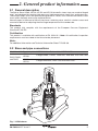
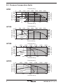
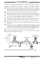
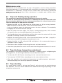
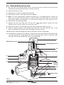
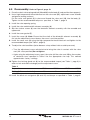
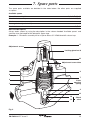
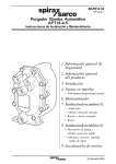
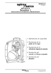
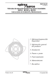
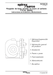
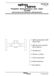
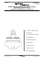
6232150/5 IM-P623-04 ST Issue 5 HP80, HP100, HP150 and HP210 Series Bimetallic Steam Traps Installation and Maintenance Instructions 1. Safety information 2. General product information 3. Installation 4. Commissioning 5. Operation 6. Maintenance 7. Spare parts 8. Fault finding IM-P623-04 Printed in the ST UKIssue 5 1 © Copyright 2007 1. Safety information Safe operation of these products can only be guaranteed if it is properly installed, commissioned, used and maintained by qualified personnel (see Section 1.11 ) in compliance with the operating instructions. General installation and safety instructions for pipeline and plant construction, as well as the proper use of tools and safety equipment must also be complied with. 1.1 Intended use Referring to the Installation and Maintenance Instructions, name-plate and Technical Information Sheet, check that the product is suitable for the intended use /application. These products comply with the requirements of the European Pressure Equipment Directive 97/23/EC and all fall within category 'SEP'. It should be noted that products within this category are required by the Directive not to carry the mark. i) The products have been specifically designed for use on steam, air or water / condensate which are in Group 2 of the above mentioned Pressure Equipment Directive. The products’ use on other fluids may be possible but, if this is contemplated, Spirax Sarco should be contacted to confirm the suitability of the product for the application being considered. ii) Check material suitability, pressure and temperature and their maximum and minimum values. If the maximum operating limits of the product are lower than those of the system in which it is being fitted, or if malfunction of the product could result in a dangerous overpressure or overtemperature occurrence, ensure a safety device is included in the system to prevent such over-limit situations. iii) Determine the correct installation situation and direction of fluid flow. iv) Spirax Sarco products are not intended to withstand external stresses that may be induced by any system to which they are fitted. It is the responsibility of the installer to consider these stresses and take adequate precautions to minimise them. v) Remove protection covers from all connections and protective film from all name-plates, where appropriate, before installation on steam or other high temperature applications. 1.2 Access Ensure safe access and if necessary a safe working platform (suitably guarded) before attempting to work on the product. Arrange suitable lifting gear if required. 1.3 Lighting Ensure adequate lighting, particularly where detailed or intricate work is required. 1.4 Hazardous liquids or gases in the pipeline Consider what is in the pipeline or what may have been in the pipeline at some previous time. Consider: flammable materials, substances hazardous to health, extremes of temperature. 2 IM-P623-04 ST Issue 5 1.5 Hazardous environment around the product Consider: explosion risk areas, lack of oxygen (e.g. tanks, pits), dangerous gases, extremes of temperature, hot surfaces, fire hazard (e.g. during welding), excessive noise, moving machinery. 1.6 The system Consider the effect on the complete system of the work proposed. Will any proposed action (e.g. closing isolation valves, electrical isolation) put any other part of the system or any personnel at risk? Dangers might include isolation of vents or protective devices or the rendering ineffective of controls or alarms. Ensure isolation valves are turned on and off in a gradual way to avoid system shocks. 1.7 Pressure systems Ensure that any pressure is isolated and safely vented to atmospheric pressure. Consider double isolation (double block and bleed) and the locking or labelling of closed valves. Do not assume that the system has depressurised even when the pressure gauge indicates zero. 1.8 Temperature Allow time for temperature to normalise after isolation to avoid danger of burns. 1.9 Tools and consumables Before starting work ensure that you have suitable tools and /or consumables available. Use only genuine Spirax Sarco replacement parts. 1.10 Protective clothing Consider whether you and /or others in the vicinity require any protective clothing to protect against the hazards of, for example, chemicals, high / low temperature, radiation, noise, falling objects, and dangers to eyes and face. 1.11 Permits to work All work must be carried out or be supervised by a suitably competent person. Installation and operating personnel should be trained in the correct use of the product according to the Installation and Maintenance Instructions. Where a formal ‘permit to work’ system is in force it must be complied with. Where there is no such system, it is recommended that a responsible person should know what work is going on and, where necessary, arrange to have an assistant whose primary responsibility is safety. Post ‘warning notices’ if necessary. 1.12 Handling Manual handling of large and /or heavy products may present a risk of injury. Lifting, pushing, pulling, carrying or supporting a load by bodily force can cause injury particularly to the back. You are advised to assess the risks taking into account the task, the individual, the load and the working environment and use the appropriate handling method depending on the circumstances of the work being done. IM-P623-04 ST Issue 5 3 1.13 Residual hazards In normal use the external surface of the product may be very hot. If used at the maximum permitted operating conditions the surface temperature of some products may reach temperatures in excess of 570°C (1058°F). Many products are not self-draining. Take due care when dismantling or removing the product from an installation (refer to ‘Maintenance instructions’). 1.14 Freezing Provision must be made to protect products which are not self-draining against frost damage in environments where they may be exposed to temperatures below freezing point. 1.15 Disposal Unless otherwise stated in the Installation and Maintenance Instructions, this product is recyclable and no ecological hazard is anticipated with its disposal providing due care is taken. 1.16 Returning products Customers and stockists are reminded that under EC Health, Safety and Environment Law, when returning products to Spirax Sarco they must provide information on any hazards and the precautions to be taken due to contamination residues or mechanical damage which may present a health, safety or environmental risk. This information must be provided in writing including Health and Safety data sheets relating to any substances identified as hazardous or potentially hazardous. 4 IM-P623-04 ST Issue 5 2. General product information 2.1 General description The Spirax Sarco HP80, HP100, HP150 and HP210 bimetallic steam traps are made of forged steel, and designed for draining high pressure, high temperature steam lines and processes. These steam traps, which are specially designed for HP steam, have a reinforced stainless steel insert within the body and can be repaired online. Normally open in the event of failure, they have a retaining valve, a built-in strainer screen and an external device for adjusting the discharge temperature of the condensate. Standards This product fully complies with the requirements of the European Pressure Equipment Directive 97/23 / EC. Certification This product is available with certification to EN 10204 3.1. Note: All certification / inspection requirements must be stated at the time of order placement. Note: For additional information see Technical Information Sheet TI-P623-06. 2.2 Sizes and pipe connections ½", ¾" and 1" Socket weld to ANSI B 16.11 or Butt weld to ANSI B 16.25. DN15, DN20 and DN25 HP80 and HP100 Flanged PN63, PN100, ANSI 600, ANSI 900 and ANSI 1500 HP150 and HP210 Flanged ANSI 900, ANSI 1500 and ANSI 2500 Fig. 1 HP80 shown IM-P623-04 ST Issue 5 5 2.3 Pressure / temperature limits HP80 Pressure psi g Temperature °C ��� ��� ���� A ���� Steam saturation curve ��� � � �� Temperature °C ���� B C ��� ��� Pressure psi g � ��� ��� A ��� ��� ��� ��� � � ��� ���� ���� ���� ���� ���� B Steam saturation curve B C �� ��� ��� Pressure bar g ��� ���� ���� ��� ��� ��� ��� ��� ��� ��� ��� D ��� ��� Temperature °F Pressure psi g � ��� ��� A ��� ��� ��� ��� � ���� ���� ���� Steam saturation curve � ��� ���� ���� ���� ��� ��� ��� ��� ��� ��� ��� ��� E ��� ��� D ��� ��� ��� Pressure bar g HP210 ���� Temperature °F Temperature °C ���� ��� ��� ��� ��� ��� ��� ��� ��� D ��� �� ��� ��� Pressure bar g HP150 Pressure psi g � ��� ��� A ��� ��� ��� ��� � � ���� ���� Steam saturation curve ��� ���� ���� D ��� ��� Pressure bar g ���� ���� ���� ��� ��� ��� ��� ��� ��� ��� ��� E ��� ��� Temperature °F Temperature °C ���� ��� ��� HP100 6 ���� B Temperature °F ��� � IM-P623-04 ST Issue 5 The product must not be used in this region. The product should not be used in this region or beyond its operating range as damage to the internals may occur. A-B A-C A-D A-E Flanged PN63 and PN100. Flanged ANSI 600. Flanged ANSI 900 and ANSI 1500 ( socket weld and butt weld HP80 and HP100). Flanged ANSI 2500 (socket weld and butt weld HP150 and HP210). PN250, Class 1500 to ANSI B 16.34 PN420, Class 2500 to ANSI B 16.34 HP80 and 100 258 bar g @ 93°C (3741 psi g @ 199°F) Maximum PMA allowable pressure HP150 and 210 431 bar g @ 93°C (6249 psi g @ 199°F) HP80 500°C @ 126 bar g (932°F @ 1827 psi g) Maximum TMA allowable temperature HP100 570°C @ 57 bar g (1058°F @ 827 psi g) HP150 and HP210 570°C @ 97 bar g (1058°F @ 1407 psi g) (6.8°F) HP80 -14°C Minimum allowable temperature HP100, 150 and 210 -22°C (-7.6°F) HP80 80 bar g @ 500°C (1160 psi g @ 932°F) HP100 100 bar g @ 530°C (1450 psi g @ 986°F) Maximum PMO operating pressure HP150 150 bar g @ 537°C (2175 psi g @ 999°F) HP210 210 bar g @ 525°C (3045 psi g @ 977°F) HP80 500°C @ 126 bar g (932°F @ 1827 psi g) Maximum TMO operating temperature HP100 570°C @ 57 bar g (1058°F @ 827 psi g) HP150 and HP210 570°C @ 97 bar g (1058°F @ 1407 psi g) Body design conditions HP80 and 100 HP150 and 210 20 bar g (290 psi g) 25 bar g (363 psi g) Minimum operating temperature 0°C (32°F) PMX Backpressure for correct operation must not exceed 90% of the upstream pressure HP80 and HP100 388 bar g (5626 psi g) Designed for a maximum cold hydraulic test pressure of: HP150 and HP210 646 bar g (9367 psi g) Minimum inlet pressure for satisfactory operation is: IM-P623-04 ST Issue 5 HP80 HP100, 150 and 210 7 3. Installation Note: Before actioning any installation observe the 'Safety information' in Section 1. Referring to the Installation and Maintenance Instructions, name-plate and Technical Information Sheet, check that the product is suitable for the intended installation: 3.1 Check materials, pressure and temperature and their maximum values. If the maximum operating limit of the product is lower than that of the system in which it is being fitted, ensure that a safety device is included in the system to prevent overpressurisation. 3.2 3.3 Determine the correct installation situation and the correct direction of fluid flow. Remove protective covers from all connections and protective film from all name-plates, where appropriate, before installation on steam or other high temperature applications. 3.4 Install the steam trapping station downstream of the equipment to be drained, ensuring that it is easily accessible for inspection and maintenance. 3.5 The steam trap may be installed in any position, except where discharge is flowing vertically upwards. Optimum performance will be achieved if installed horizontally. 3.6 3.7 Before installing the trap, ensure all connecting pipework is clean and free of debris. Mount the steam trap with the arrow on the body pointing in the direction of the flow of the liquid. 3.8 The steam trap can be welded onto the pipework without removing the internal components. If there is any possibility of the line freezing, the axis of the bonnets should be installed horizontally. For socket welded traps, observe qualified welding procedures. It is not necessary to remove the trap internals when welding, but avoid excessive heat. 3.9 The steam trap is factory set at 45°C below steam stauration temperature. Note: If the trap is to discharge to atmosphere ensure it is to a safe place, the discharging fluid may be at a temperature of 100°C (212°F). Drain connection Gate valve (Downstream valve) Gate valve HP series trap 0.61 metres (24") 1 metre minimum (3 ft) Test valve Fig. 2 Recommended installation - Note: pipework to fall in the direction of flow. 8 IM-P623-04 ST Issue 5 4. Commissioning After installation or maintenance ensure that the system is fully functioning. Carry out tests on any alarms or protective devices. Note: During commissioning the valve may need resetting to take account of any backpressure in the return line. 5. Operation The Spirax Sarco HP80, HP100, HP150 and HP210 are bimetallic steam traps. These traps operate on the basis of two opposing forces acting on the valve - an opening force created by the valve opening spring, and a closing force resulting from the condensate temperature acting on the bimetallic elements. They operate with no loss of steam and automatically and quickly drains air, non-condensable gases and large quantities of cold water on start-up. 6. Maintenance Important note: Before actioning any maintenance programme observe the 'Safety information' in Section 1. Safety note: These traps are installed in high pressure steam lines. Personnel doing the adjustment work should wear heavy gloves, long sleeve shirt, and other safety equipment designed to protect the wearer (goggles, face shield, etc.) in the event of a leak. The equipment needed to proceed with any maintenance programme is listed in Table 1. The HP80, HP100, HP150 and HP210 have an external adjustment screw, which permits the flushing of the trap seat and the setting of the discharge temperature of the condensate in the inlet line allowing optimum performance to be achieved. Table 1 Spanners to be used and recommended tightening torques or Item Part Nm (lbf ft) 36 A / F 21 A / F 24 A / F 24 A / F 30 A/F 120 25 120 160 200 (88) (18) (88) (118) (148) 41 A / F 55 A / F 80 140 (59) (103) mm 3 6 9 11 Bimetallic element - pipe spanner Locking gland nut on adjustment screw HP80 Cover nut HP100 HP150 and HP210 Blind nut HP80 and HP100 HP150 and HP210 IM-P623-04 ST Issue 5 9 Maintenance note: Maintenance can be completed with the trap in the pipeline, once the safety procedures have been observed. It is recommended that new gaskets and spares are used whenever maintenance is undertaken. Ensure that the correct tools and necessary protective equipment are used at all times. When maintenance is complete open isolation valves slowly and check for leaks. 6.1 Trap seat flushing during operation This maintenance operation should be performed once every six months. To clean the steam trap during operation, it is advisable to close the steam inlet valve before turning the adjustment screw, and proceed as follows: (in a closed return system, close the discharge line and open the test valve): - Remove the blind nut (11) and loosen the locking gland nut (6) by turning clockwise. Note: the gland nut and adjustment screw have left hand threads. - Using a screwdriver, loosen the adjustment screw a few turns, clockwise. This completely disengages the valve from the valve seat (12). - Open the steam inlet valve slightly. This causes a strong purging action, which removes any impurities that may have been deposited in the steam trap. - Turn the adjustment screw anticlockwise until the valve comes into contact with the valve seat (12). Turn through a further ¼ turn anticlockwise. - Retighten the locking gland nut (6) to the recommended torque (see Table 1, page 9) in order to lock and reduce leakage past the adjustment screw. - Replace the blind nut (11) and gasket (10) and tighten to the recommended torque as specified in Table 1, page 9. - Shut the test valve and open the discharge line valve and check for leaks. Allow the trap to operate for several minutes and review the operation to ensure it is correct. 6.2 Trap discharge temperature adjustment This procedure is the same as that given in Section 6.1. However, prior to re-tightening the locking gland nut, the discharge temperature may be adjusted as follows: - To reduce by 10°C (50°F) (more subcooling), turn the screw anticlockwise ¼ turn. To increase by 10°C (50°F) (less subcooling), turn the screw clockwise ¼ turn. Allow trap operation and condensate temperature to stabilise between adjustments. Continue adjusting until satisfactory operation is obtained. 6.3 Trap checking In a closed return system, a test tee (see Figure 2) and valve must be used to observe trap operation. The trap should modulate the condensate discharge depending on inlet temperature and pressure. 10 IM-P623-04 ST Issue 5 6.4 Disassembly and service 1. Shut the trap inlet and discharge valves, vent the pressure and allow the trap to cool sufficiently to prevent possible injury from hot surfaces. 2. Remove the blind nut (11). 3. Remove the six cover nuts (9) and the cover (8). 4. Remove the strainer screen (4) and clean or replace. 5. Note: The valve and bimetallic element assembly (3) is assembled loosely. Carefully lift these as one piece from the body (1). Take the necessary precautions to ensure that the bimetal element arrangement is not disturbed. Inspect the valve plug for wear. 6. Remove the valve opening spring. 7. Remove the valve seat (12) with a 36 mm A / F (1 seating surface and the check valve seat for wear. ") pipe wrench. Inspect the valve 8. Remove the check valve ball (13) and check valve spring and inspect for wear. 9. Clean all gasket surfaces and remove dirt /scale from the trap internals with a wire brush or equivalent. Be careful not to damage the sealing surfaces. 10. Blow out the trap inlet piping and clean the upstream strainer if applicable. 11. The bimetallic assembly kit (see Section 7, Spare parts) consists of the bimetallic element (3), valve seat gasket (2), cover gasket (7), blind nut gasket (10), strainer screen (4), valve seat (12), check valve ball (13) and check valve spring (14). 11 Adjustment screw Locking gland nut 6 10 Adjustment screw tube 9 3 8 7 Valve opening spring 4 12 2 13 14 Check valve 1 Fig. 3 IM-P623-04 ST Issue 5 11 6.5 Reassembly: Refer to Figure 4, page 13. 1. Place the check valve spring and ball (13 and 14) into the body (1) and position them properly. 2. Use a high temperature thread lubricant on the valve seat (12), adjustment screw threads and gasket seating surfaces. Put the valve seat gasket (2) in place and thread the valve seat (12) into the body (1). Tighten to the recommended torque as specified, in Table 1, page 9. 3. Install the valve opening spring. 4. Install the valve and bimetallic element assembly (3). 5. Slip the strainer screen (4) over the bimetallic element assembly with the rounded end uppermost. 6. Install the cover gasket (7). 7. Install the cover (8). Note: Ensure that the shaft of the bimetallic element assembly (3) fits into the adjustment screw tube as the cover is put into position. 8. Install the cover nuts (9) using the high temperature thread lubricant and tighten to the recommended torque (see Table 1, page 9). 9. To adjust for cold conditions (to be done on a trap without inlet or outlet pressure): - Turn the adjustment screw anticlockwise to bring the valve in contact with the valve seat (12 - close position) Do not tighten. - Again using the adjustment screw, open' the valve (off the valve seat 12) by the number of clockwise turns specified in Table 2 for the appropriate size trap. This method approximates factory settings. 10. Tighten the locking gland nut (6) to the recommended torque (see Table 1, page 9) in order to lock and reduce leakage past the adjustment screw. Table 2 Trap series Setting (full turns clockwise) HP80 3½ HP100 4¼ HP150 5 HP210 5¼ 11. Install the blind nut and gasket (10 and 11) and torque as specified in Table 1, page 9. 12 IM-P623-04 ST Issue 5 7. Spare parts The spare parts available are detailed in the table below. No other parts are supplied as spares. Available spares Bimetallic assembly kit 2, 3, 4, 7, 10, 12 Check valve assembly 13, 14 Strainer screen 4 Cover gasket set (packet of 3) 7 2, 7, 10 Gasket set How to order spares Always order spares by using the description in the column headed 'Available spares' and state the size and model of the bimetallic steam trap. Example: 1 - Bimetallic assembly kit for a Spirax Sarco ½" HP80 bimetallic steam trap. 11 Adjustment screw Locking gland nut 6 10 Adjustment screw tube 9 3 8 7 4 Valve opening spring 1 2 12 13 14 Check valve Fig. 4 IM-P623-04 ST Issue 5 13 8. Fault finding 1. Make sure upstream and downstream valves are open. 2. Check external strainers for clogging; blowdown or dismantle and clean. Trap fails to pass condensate 3. Valve port clogged with dirt. Follow 'Trap seat flushing' procedure (See Section 6.1). 4. Bimetallic element improperly adjusted. Adjust as described under 'Trap discharge temperature adjustment' (See Section 6.2). 5. Dismantle and inspect internals. See 'Disassembly and service' (See Section 6.4). 1. Dirt on seating surface. Flush as described in 'Trap seat flushing' procedure (See Section 6.1). Trap blows live steam 2. Bimetallic element improperly adjusted. Adjust as described under 'Trap discharge temperature adjustment' (See Section 6.2). 3. Worn valve seat. Dismantle, inspect and replace if necessary. Note: The seat and bimetallic element must be replaced as a matched pair. 4. Backpressure too high. Downstream system must be corrected. 14 IM-P623-04 ST Issue 5 IM-P623-04 ST Issue 5 15 16 IM-P623-04 ST Issue 5