1
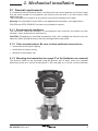
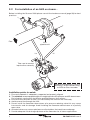
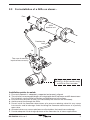
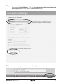
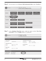
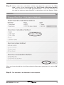
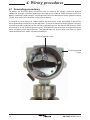
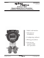
IM-P335-24
3352051/2
MI Issue 2
Scanner 2000
Steam Mass Flow Transmitter
Installation and Maintenance Instructions
1.Safety information
2.Mechanical
installation
3.Configuring software
4. Wiring procedures
5.Placing the
Scanner 2000
into operation
Printed in theMI
UKIssue 2
IM-P335-24
© Copyright 2011
1
1. Safety information
Safe operation of this product can only be guaranteed if it is properly installed,
commissioned, used and maintained by qualified personnel in compliance with the
operating instructions. General installation and safety instructions for pipeline and
plant construction, as well as the proper use of tools and safety equipment must
also be complied with.
1.1 Intended use
Referring to the Installation and Maintenance Instructions, name-plate and Technical
Information Sheet, check that the product is suitable for the intended use / application.
i) Check material suitability, pressure and temperature and their maximum and
minimum values. If the maximum operating limits of the product are lower than
those of the system in which it is being fitted, or if malfunction of the product
could result in a dangerous overpressure or overtemperature occurrence, ensure
a safety device is included in the system to prevent such over-limit situations.
ii) Determine the correct installation situation and direction of fluid flow.
iv) Spirax Sarco products are not intended to withstand external stresses that may
be induced by any system to which they are fitted. It is the responsibility of the
installer to consider these stresses and take adequate precautions to minimise
them.
v) Remove protection covers from all connections and protective film from all
name-plates, where appropriate, before installation on steam or other high
temperature applications.
2
IM-P335-24 MI Issue 2
2. Mechanical installation
2.1 General requirements
It is important that the Scanner 2000 is installed with the correct pipeline unit. Please check
that the serial number on the pipeline unit matches the one that is on the Scanner 2000
application tag.
The installation must conform to all relevant construction and electrical codes.
Warning: The standard Scanner 2000 is not approved for hazardous area applications.
CSA /FM and ATEX / CENELEC versions are available on request.
2.1.1 Environmental conditions
The transmitter should be located in an environment that minimises the effects of heat,
vibration, shock and electrical interference.
CAUTION: Exceeding the specified temperature limits will invalidate the warranty and can
adversely affect the performance and may damage the Scanner 2000
2.1.2 Other considerations: Be sure to allow sufficient clearance for:
-
-
-
Installation of the impulse piping.
Installation of conduit wiring.
Removal of the display cap.
2.1.3 Mounting the transmitter (see page 27 of the Hardware user manual)
The Scanner 2000 can be mounted using the bracket and 'U' bolts which are supplied.
Mounting can be to a vertical or horizontal 2" (50 mm) pipe, or it can be surface mounted.
IM-P335-24 MI Issue 2
3
2.2 For installation of an ILVA on steam: Before installing the Scanner 2000 please consult the hardware manual (page 39) for best
practices.
Flow
ILVA
pipeline unit
Lo
Hi
Take care to connect
impulse lines correctly
Building management system or
SCADA (4 - 20 mA versions only)
or M750 or Chart recorder
Installation points to watch:
1. Ensure all pipework is adequately supported and properly aligned.
2. The minimum recommended lengths of straight pipe are 6D upstream and 3D downstream.
For full details see the ILVA Installation and Maintenance Instructions.
3. Ensure correct direction of flow is as indicated by the arrow on the ILVA body.
4. Avoid reverse flow through the ILVA.
5. Do not install the flowmeter downstream of a pressure reducing valve this may cause
inaccuracies and /or damage. Avoid installing the flowmeter downstream of a partially
open valve.
6. Actuated valves may cause rapid pressure fluctuations that could cause damage.
7. Provide adequate line drainage upstream of the flowmeter for all steam applications.
4
IM-P335-24 MI Issue 2
2.3 For installation of a Gilflo on steam: -
Flow
Gilflo
pipeline unit
Condensate
level
Lo
Hi
Take care to connect
impulse lines correctly
Building management system or
SCADA (4 - 20 mA versions only)
or M750 or Chart recorder
Installation points to watch:
1. Ensure all pipework is adequately supported and properly aligned.
2. The minimum recommended lengths of straight pipe are 6D upstream and 3D downstream.
For full details see the Gilflo Installation and Maintenance Instructions
3. Ensure correct direction of flow is as indicated by the arrow on the Gilflo body.
4. Avoid reverse flow through the Gilflo.
5. Do not install the flowmeter downstream of a pressure reducing valve this may cause
inaccuracies and / or damage. Avoid installing the flowmeter downstream of a partially
open valve.
6. Actuated valves may cause rapid pressure fluctuations that could cause damage.
7. Provide adequate line drainage upstream of the flowmeter for all steam applications.
IM-P335-24 MI Issue 2
5
3. Configuring software
Please note that if the Scanner 2000 has been supplied as part of an ILVA
or Gilflo system, this option will have been configured during manufacture.
Note:A DB9 Serial RS232 to RS485 converter will be required to connect your PC to the
Scanner 2000 if it does not have an RS485 serial port. If your PC only has USB ports, a
USB to DB9 Serial port converter will be required. These are available from most electronics
suppliers.
Step 1 - Make sure that the Scanner 2000 is connected to a laptop or PC and power has
been supplied to the unit.
Step 2 - Start the selection process by opening the ModWorx pro software. Open the
software by double clicking on the Icon shown below:
(Version numbers may vary)
Step 3 - Click on the 'connect' button as shown below:
6
IM-P335-24 MI Issue 2
Step 4 - Make sure that the 'Express Connect' option has been selected in the drop down
box, entitled 'Select Method'. Tick the 'Use default permissions of connected
device port' box and click on the 'connect now' button.
Step 5 - On the following screen please select 'Configure'.
IM-P335-24 MI Issue 2
7
Step 6 - From the options on the 'Scanner 2000 Configuration Menu' select 'Flow Run 1'.
Step 7 - In the 'Configure Flow Run' menu, under the section entitled 'Flow Rate
Calculation', click the 'Change' button as circled below:
8
IM-P335-24 MI Issue 2
Step 8 - Please select your calculation method, and flowmeter type from the 'Flow
Run 1' menu. In the example below, the 'IF-97 Steam Calculation Method'
has been selected with the 'ILVA type Flowmeter', as the ILVA flowmeter will
be used to measure steam flowrate in conjunction with the Scanner 2000:
When you have selected the calculation method and flowmeter type please click on the 'OK'
button.
Step 9 - The selection of the flowmeter is now complete.
IM-P335-24 MI Issue 2
9
4. Wiring procedures
4.1 Grounding procedures
To power the Scanner 2000 microEFM with an external dc supply, route the ground
conductor through a conduit opening in the top of the scanner 2000 enclosure with the
power conductors and connect it to the ground screw inside the enclosure (note the round
sticker that marks this location in the picture below).
If national or local electrical codes require the enclosure to be grounded, a protective
earth-grounding conductor may be required. To install a protective earth ground, connect
an earth ground conductor to the stainless ground lug near the top of the Scanner 2000
enclosure or to the internal ground screw, and connect the other end to a ground rod or
other suitable system earth ground. The ground lugs will accept wire sizes from 14 AWG
solid conductor to 4 AWG stranded conductor.
Internal ground screw
External ground
screw
10
IM-P335-24 MI Issue 2
4.2 4 - 20 mA analogue output
The 4 - 20 mA output provides a linear current output that can be configured using ModWorX
Pro software to represent any parameter in the holding registers. This output requires a
two-conductor cable to be connected to an 8 to 30 Vdc power supply (voltage required is
dependent on loop resistance) and a current readout device to be located in the remote
location. See the ModWorX Pro Software User Manual for information on configuring zero
and full-scale values using ModWorX software.
Analog output (TB4)
with power supplied via main board (TB2)
Analog device
Power supply
8 - 30 Vdc
-
+
TB5
TB4
GND +
+ -
15
A resistor may
be included in the
readout device
16
Power
+
-
8
9
TB6
TB7
10
11
TB9
Expansion
board PN:
9A-30160014
TB8
Ground screw
inside enclosure
7
12
TB2
Scanner 2000
main circuit board
PN: 9A-30160010
IM-P335-24 MI Issue 2
11
4.3 External power supply
The Scanner 2000 can be connected to a remote power supply by a two-conductor cable.
The power supply and cable must be capable of supplying 6 to 30 Vdc @ 31 mA.
The external power supply must be approved SELV source, insulated from the ac main by
double / reinforced insulation per CSA C 22.2 No. 61010-104 / UL 61010-1 – 2nd Edition.
Important: In all applications using an external power supply, a switch or circuit breaker
must be included in the safe area external power supply installation within easy reach of the
operator. The switch or circuit breaker must be marked as the "disconnect" for the safe area
external dc power supply.
Important: If the main circuit board is marked with a revision level of 02 or older (revisions
01, C, B, or A), a zener diode (Part No. 1.5 KE33CA) must be installed for CE approval. The
zener diode is not required for revision 03 and newer circuit boards.
+
4
6
J2
TB1
Sw
Ground screw
inside enclosure
12
Scanner 2000
main circuit board
PN: 9A-30160010
i tc
Port 1
+
-
5
Port 2
+
-
3
RTD
R+ R-
2
+
1
TMN
+
-
GND
-
Power
+
-
Power
supply
6 - 30
Vdc
7
8
9
10
11
12
TB2
13
h
D IG
OU
14
Battery
T1
TB3
J1
IM-P335-24 MI Issue 2
4.4 Output wiring
4.4.1 Digital output (Pulse or Alarm)
The standard Scanner 2000 supports a solid-state digital output that is configurable as
either a pulse output or an alarm output. As a pulse output, the pulse width duration and
pulse representation are both configurable. Because the circuit is isolated, it can be used
in conjunction with any other feature on the Scanner 2000. A two-conductor cable from the
Scanner 2000 to the remote location is required. The maximum rating of the digital output
circuit is 60 mA at 30 Vdc.
For reduced power consumption, turn the digital output feature off when it is not in use.
Important: If the main circuit board is marked with a revision level of 02 or older (revisions
01, C, B, or A), a zener diode (Part No. 1.5 KE33CA) must be installed for CE approval. The
zener diode is not required for revision 03 and newer circuit boards.
Power supply
6 - 30 Vdc
+
A resistor may be
included in the pulse
readout device. Size
the resistor to limit the
current to 60 mA.
6
J2
RTD
R+ R-
Port 1
+
-
5
+
4
Port 2
+
-
3
Scanner 2000
main circuit board
PN: 9A-30160010
TMN
+
-
2
Power
+
-
1
Pulse readout
device
+ -
TB1
Sw
i tc
h
Leave the end of this
shield disconnected
13
7
8
9
10
11
12
TB2
14
Battery
TB3
J1
4.4.2 RS232 / RS485 interface converter
Cameron can supply the parts: 9A - 101283116
RS-232 to RS-485 converter, Serial Port Powered, DB9 Connector on PC End,
Open Terminals on Instrument End
Alternatively a suitable RS232 / RS485 converter can be supplied from RS Components or
your local electronic supplier.
IM-P335-24 MI Issue 2
13
5. Placing the Scanner 2000
into operation
To put the scanner into operation:
Step 1 - Make sure that all valves on the
Manifold
Closed
manifold are in the closed
position.
DP cell
Closed
Step 2 - Ensure impulse lines have
Closed
Manifold
Open
been primed with cold water
or antifreeze (depending on
application).
Closed
Step 3 - Open isolation valves and
bleed valves on manifold
to purge the Scanner 2000
of air.
DP cell
Open
14
Open
IM-P335-24 MI Issue 2
Step 4 - Shut off isolation valves at the
Flowmeter
flowmeter and the bleed valves
on the manifold.
Closed
Manifold
Open
Closed
DP cell
Closed
Closed
Step 5 - Turn the system pressure on
Flowmeter
(optional but recommended)
Step 6 - Open equalization valve.
Closed
Manifold
Open
Open
DP cell
Closed
IM-P335-24 MI Issue 2
Closed
15
Step 7 - Check the 4 mA output.
Flowmeter
Step 8 - Close the equalization valve.
Closed
Manifold
Open
Closed
DP cell
Closed
Closed
Step 9 - Open isolation valves on the
Flowmeter
impulse lines at the flowmeter.
Open
Manifold
Open
Closed
DP cell
Closed
16
Closed
IM-P335-24 MI Issue 2