1
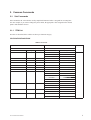
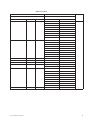
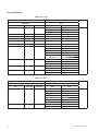
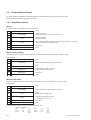
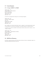
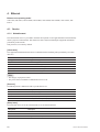
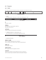
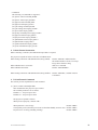
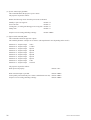
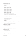
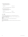
DATA PROJECTOR
VPL-EX100
VPL-EX120
VPL-EX145
VPL-EX175
VPL-FX30
VPL-FX35
VPL-FX500L
VPL-F400X
VPL-F500X
VPL-F700XL
PROTOCOL MANUAL
1st Edition (Revised 2)
! 警告
このマニュアルは,サービス専用です。
お客様が,このマニュアルに記載された設置や保守,点検,修理などを行うと感電や火災,
人身事故につながることがあります。
危険をさけるため,サービストレーニングを受けた技術者のみご使用ください。
! WARNING
This manual is intended for qualified service personnel only.
To reduce the risk of electric shock, fire or injury, do not perform any servicing other than that
contained in the operating instructions unless you are qualified to do so. Refer all servicing to
qualified service personnel.
! WARNUNG
Die Anleitung ist nur für qualifiziertes Fachpersonal bestimmt.
Alle Wartungsarbeiten dürfen nur von qualifiziertem Fachpersonal ausgeführt werden. Um die
Gefahr eines elektrischen Schlages, Feuergefahr und Verletzungen zu vermeiden, sind bei
Wartungsarbeiten strikt die Angaben in der Anleitung zu befolgen. Andere als die angegeben
Wartungsarbeiten dürfen nur von Personen ausgeführt werden, die eine spezielle Befähigung
dazu besitzen.
! AVERTISSEMENT
Ce manual est destiné uniquement aux personnes compétentes en charge de l’entretien. Afin
de réduire les risques de décharge électrique, d’incendie ou de blessure n’effectuer que les
réparations indiquées dans le mode d’emploi à moins d’être qualifié pour en effectuer d’autres.
Pour toute réparation faire appel à une personne compétente uniquement.
VPL Series PROTOCOL MANUAL
Table of Contents
1. Overview
1-1.
Introduction ........................................................................ 1
1-2.
Glossary of Terms .............................................................. 1
1-3.
Protocol Stack Structure ..................................................... 1
2. Common Commands
2-1. Sub Commands .................................................................. 3
2-1-1.
ITEM List ................................................................. 3
2-1-2.
Infrared Remote Command Code ........................... 12
2-2.
Reply ................................................................................ 15
3. RS-232C
3-1.
Connection ....................................................................... 16
3-2.
Communication Specifications......................................... 16
3-3. Communication Procedure ............................................... 17
3-3-1.
Outline of Communication ..................................... 17
3-4.
Communication Rules ...................................................... 17
3-5.
Approximate Return Waiting Times................................. 17
3-6. Command Block Format .................................................. 18
3-6-1.
Simplified Command .............................................. 18
3-7. Packet Examples .............................................................. 19
3-7-1.
Change “ASPECT” to “ZOOM” ............................ 19
3-8.
AMX Device Discovery ................................................... 19
4. Ethernet
4-1. Service .............................................................................. 20
4-1-1.
Advertisement ......................................................... 20
4-1-2.
PJ Talk..................................................................... 21
4-2.
Communication Procedure ............................................... 22
4-3. Protocols ........................................................................... 23
4-3-1.
SDAP ...................................................................... 23
4-3-2.
SDCP....................................................................... 24
4-3-3.
SNMP...................................................................... 32
4-3-4.
PJLink ..................................................................... 33
4-3-5.
DDDP...................................................................... 40
VPL Series PROTOCOL MANUAL
1 (T)
1. Overview
1-1. Introduction
The projector is remotely controllable over RS-232C as well as Ethernet. It is useful for setting up the
projector away from the operator.
This protocol manual describes the specifications such as packet format and procedures for controlling the
projector.
In the following sections below, the term “CONTROLLER” is used as a device which controls the projector. CONTROLLER can be a PC or other specific device that is able to handle RS-232C or Ethernet.
Although most of commands are available for both RS-232C and Ethernet, some commands are dedicated
to Ethernet.
* Ethernet is a registered trademark of Xerox Corporation.
1-2. Glossary of Terms
Table 1-1 Glossary of Terms
Terms
Abbreviated
Description
CONTROLLER
_
Command initiator such as PCs.
PROJECTOR
_
Front projector.
SDAP
Simple Display Advertisement Protocol
Protocol name for advertising the projector status over
Ethernet.
SDCP
Simple Display Control Protocol
Protocol name for controlling projector over Ethernet.
PJLink
_
Protocol name for controlling projector over Ethernet.
DDDP
Dynamic Device Discovery Protocol
AMX Device Discovery is the protocol name by AMX
to enable to configure the AMX control system and
other intended devices.
1-3. Protocol Stack Structure
The protocol stack structure diagram is shown below. Though the stack is drawn for RS-232C and Ethernet separately, the following portions are common.
Table 1-2 Common Portions in Protocol Stack
Layer Name
Description
Sub Command
Value is assigned for projector’s functions. Refer to the section 2-1 for detail description.
Simplified Command
Packet format for sending/receiving “Sub Command”. Refer to the section 3-6-1 for detail
description.
VPL Series PROTOCOL MANUAL
1
(1) RS-232C
Sub Command
AMX Device
Discovery
Simplified Command
Asynchronous
RS-232C
Fig. 1-1 RS-232C Protocol Stack
“RS-232C” layer is physical portion and “Asynchronous” is the traditional protocol layer as shown in the
section 3-2.
(2) Ethernet
SDCP Specific Command
HTTP
Sub
Command
PJLink
SNMP
SDAP
DDDP
Simplified
Command
SDCP (PJ Talk)
UDP/IP
TCP/IP
Ethernet
Fig. 1-2 Ethernet Protocol Stack
Ethernet corresponding model
VPL-FX30, VPL-FX35, VPL-FX500L, VPL-F400X, VPL-F500X, VPL-F700XL, VPL-EX145, VPLEX175
Because of traditional portions for Ethernet general layer, “TCP/IP”, “UDP/IP”, “HTTP” and “SNMP”
are out of scope in this document.
SDCP specific command is described in the section 4-3-2.
SDAP and SDCP (PJ Talk) are SONY original protocol stack, which are described in the sections 4-3-1
and 4-3-4 respectively.
2
VPL Series PROTOCOL MANUAL
2. Common Commands
2-1. Sub Commands
Sub Command is the value which is used by Simplified Command. Value is assigned for executing function. For example, if you want to change the picture mode, the appropriate value assigned for the desired
picture mode should be chosen.
2-1-1. ITEM List
Item lists are described below. Tables are shown per function category.
VPL-FX30/FX35/F400X/F500X
ITEM List For Picture
<Table 1>
<Table 2>
Item Number
Data
Remarks
Item
Upper byte
Lower byte
Data
Byte
PICTURE MODE
00h
02h
DYNAMIC
0000h
STANDARD
0001h
CONTRAST
00h
10h
PRESENTATION
0002h
VALUE
0000h-0064h(0-100)
BRIGHTNESS
00h
11h
VALUE
0000h-0064h(0-100)
COLOR
00h
12h
VALUE
0000h-0064h(0-100)
HUE
00h
13h
VALUE
0000h-0064h(0-100)
SHARPNESS
00h
14h
VALUE
0000h-0064h(0-100)
EXT. OUTPUT VOLUME
00h
16h
VALUE
0000h-0064h(0-100)
COLOR TEMP
00h
17h
HIGH
0000h
MID
0001h
BLACK LEVEL ADJ
FILM MODE
GAMMA MODE
VPL Series PROTOCOL MANUAL
00h
00h
00h
1Ch
1Fh
22h
LOW
0002h
CUSTOM1
0005h
CUSTOM2
0006h
CUSTOM3
0007h
OFF
0000h
LOW
0001h
HIGH
0002h
OFF
0000h
AUTO
0001h
TEXT
0000h
GRAPHIC
0001h
Set/Get
3
ITEM List For Screen
<Table 1>
<Table 2>
Item Number
Data
Item
Upper byte
Lower byte
ASPECT
00h
20h
OVER SCAN
00h
23h
Remarks
Data
Byte
FULL
0000h
NORMAL
0001h
ZOOM
0003h
FULL1
0007h
FULL2
0008h
4:3
0009h
16:9
000Ah
OFF
0000h
ON
0001h
Set/Get
ITEM List For Setup
<Table 1>
<Table 2>
Item Number
Data
Remarks
Item
Upper byte
Lower byte
Data
Byte
INPUT TERMINAL
00h
01h
VIDEO
0000h
SVIDEO
0001h
INPUTA
0002h
INPUTB
0003h
INPUTC
0004h
PICTURE MUTING
00h
30h
OFF
0000h
ON
0001h
AUDIO MUTING
00h
31h
OFF
0000h
ON
0001h
INPUT A SIGNAL-SEL
00h
32h
AUTO
0000h
COMPUTER
0001h
COMPONENT
0002h
VIDEO GBR
0003h
HIGH
0000h
STANDARD
0001h
LAMP MODE
00h
40h
Set/Get
ITEM List For Infrared Remote Command
<Table 1>
<Table 2>
Item Number
Data
Remarks
Item
Upper byte
Lower byte
Data
Upper byte
Lower byte
Infrared Remote Command
(15 bit category)
17h
Refer to Section
2-1-2.*1
_
00h
00h
Infrared Remote Command
(20 bit E category)
19h
_
00h
00h
Infrared Remote Command
(20 bit EE category)
1Bh
_
00h
00h
Set only
*1: For using this item number, the simulation of the infrared remote controller is enable. Select the corresponding code in the table of
Section 2-1-2 and use it as the lower byte of the item number.
n Other value is assigned depending for category.
4
VPL Series PROTOCOL MANUAL
ITEM List For Status
<Table 1>
<Table 2>
Item Number
Data
Item
Upper byte
Lower byte
STATUS ERROR1
01h
01h
STATUS POWER
01h
02h
Remarks
Data
Byte
NO ERROR
00h
LAMP ERROR
01h
FAN ERROR
02h
COVER ERROR
04h
TEMP ERROR
08h
D5V ERROR
10h
POWER ERROR
20h
WARNING TEMP
40h
NVM DATA ERROR
80h
STANDBY
00h
START UP
01h
STARTUP LAMP
02h
POWER ON
03h
COOLING1
04h
COOLING2
05h
SAVING COOLING1
06h
SAVING COOLING2
07h
SAVING STANDBY
08h
LAMP TIMER
01h
13h
VALUE
xxh
xxh
SUB ROM VERSION
01h
1Dh
VALUE
MAIN ROM VERSION
01h
1Eh
VALUE
xxh
STATUS SECURITY
01h
1Fh
DISABLE
00h
ENABLE
01h
STATUS ERROR2
01h
25h
NO ERROR
00h
Don’t Use
01h
Don’t Use
02h
Don’t Use
04h
Don’t Use
08h
Don’t Use
10h
NVM DATA VERSION
VPL Series PROTOCOL MANUAL
01h
27h
WARNING HIGHLAND
20h
Don’t Use
40h
Don’t Use
80h
VALUE
xxh
Get only
5
VPL-FX500L/F700XL
ITEM List For Picture
<Table 1>
<Table 2>
Item Number
Data
Remarks
Item
Upper byte
Lower byte
Data
Byte
PICTURE MODE
00h
02h
DYNAMIC
0000h
STANDARD
0001h
PRESENTATION
0002h
Set/Get
CONTRAST
00h
10h
VALUE
0000h-0064h(0-100)
BRIGHTNESS
00h
11h
VALUE
0000h-0064h(0-100)
COLOR
00h
12h
VALUE
0000h-0064h(0-100)
HUE
00h
13h
VALUE
0000h-0064h(0-100)
SHARPNESS
00h
14h
VALUE
0000h-0064h(0-100)
COLOR TEMP
00h
17h
HIGH
0000h
MID
0001h
BLACK LEVEL ADJ
FILM MODE
GAMMA MODE
00h
00h
00h
1Ch
1Fh
22h
LOW
0002h
CUSTOM1
0005h
CUSTOM2
0006h
CUSTOM3
0007h
OFF
0000h
LOW
0001h
HIGH
0002h
OFF
0000h
AUTO
0001h
TEXT
0000h
GRAPHIC
0001h
ITEM List For Screen
<Table 2>
Item Number
Data
Remarks
Item
Upper byte
Lower byte
Data
Byte
ASPECT
00h
20h
FULL
0000h
NORMAL
0001h
ZOOM
0003h
FULL1
0007h
FULL2
0008h
4:3
0009h
OVER SCAN
6
<Table 1>
00h
23h
16:9
000Ah
OFF
0000h
ON
0001h
Set/Get
VPL Series PROTOCOL MANUAL
ITEM List For Setup
<Table 1>
<Table 2>
Item Number
Data
Item
Upper byte
Lower byte
INPUT TERMINAL
00h
01h
PICTURE MUTING
00h
INPUT A SIGNAL-SEL
30h
00h
32h
PICTURE MUTING
MODE
00h
3dh
LAMP MODE
00h
40h
LAMP LIGHT MODE
00h
41h
Remarks
Data
Byte
VIDEO
0000h
SVIDEO
0001h
INPUTA
0002h
INPUTB
0003h
INPUTC
0004h
OFF
0000h
ON
0001h
AUTO
0000h
COMPUTER
0001h
COMPONENT
0002h
VIDEOGBR
0003h
IMAGE
0000h
SHUTTER
0001h
HIGH
0000h
STANDARD
0001h
AUTO
0001h
FIXED LAMP1
0002h
FIXED LAMP2
0003h
Set/Get
ITEM List For Infrared Remote Command
<Table 1>
<Table 2>
Item Number
Data
Remarks
Item
Upper byte
Lower byte
Data
Upper byte
Lower byte
Infrared Remote Command
(15 bit category)
17h
Refer to Section
2-1-2.*1
_
00h
00h
Infrared Remote Command
(20 bit E category)
19h
_
00h
00h
Infrared Remote Command
(20 bit EE category)
1Bh
_
00h
00h
Set only
*1: For using this item number, the simulation of the infrared remote controller is enable. Select the corresponding code in the table of
Section 2-1-2 and use it as the lower byte of the item number.
n
Other value is assigned depending for category.
VPL Series PROTOCOL MANUAL
7
ITEM List For Status
<Table 1>
<Table 2>
Item Number
Data
Item
Upper byte
Lower byte
STATUS ERROR1
01h
01h
STATUS POWER
8
01h
02h
Remarks
Data
Byte
NO ERROR
00h
LAMP ERROR
01h
FAN ERROR
02h
COVER ERROR
04h
TEMP ERROR
08h
D5V ERROR
10h
POWER ERROR
20h
WARNING TEMP
40h
NVM DATA ERROR
80h
STANDBY
00h
START UP
01h
STARTUP LAMP
02h
POWER ON
03h
COOLING1
04h
COOLING2
05h
SAVING COOLING1
06h
SAVING COOLING2
07h
SAVING STANDBY
08h
LAMP TIMER
01h
13h
VALUE
xxh
xxh
SUB ROM VERSION
01h
1Dh
VALUE
MAIN ROM VERSION
01h
1Eh
VALUE
xxh
STATUS SECURITY
01h
1Fh
DISABLE
00h
ENABLE
01h
STATUS ERROR2
01h
25h
NO ERROR
00h
LENS SHUTTER ERROR
01h
Don’t Use
02h
Don’t Use
04h
Don’t Use
08h
Don’t Use
10h
WARNING HIGHLAND
20h
Don’t Use
40h
LAMP SWITCHING
ERROR
80h
NVM DATA VERSION
01h
27h
VALUE
xxh
LAMP TIMER2
01h
2Bh
VALUE
xxh
STATUS LAMP
01h
2Dh
NO ERROR
00h
LAMP1 NG
01h
LAMP2 NG
02h
ALL LAMP NG
03h
Get only
VPL Series PROTOCOL MANUAL
VPL-EX100/EX120/EX145/EX175
ITEM List For Picture
<Table 1>
<Table 2>
Item Number
Data
Remarks
Item
Upper byte
Lower byte
Data
Byte
PICTURE MODE
00h
02h
DYNAMIC
0000h
STANDARD
0001h
PRESENTATION
0002h
GAME
0003h
LIVING
0004h
CINEMA
0005h
CONTRAST
00h
10h
VALUE
0000h-0064h(0-100)
BRIGHTNESS
00h
11h
VALUE
0000h-0064h(0-100)
COLOR
00h
12h
VALUE
0000h-0064h(0-100)
HUE
00h
13h
VALUE
0000h-0064h(0-100)
SHARPNESS
00h
14h
VALUE
0000h-0064h(0-100)
VOLUME
00h
16h
VALUE
0000h-0064h(0-100)
COLOR TEMP
00h
17h
HIGH
0000h
FILM MODE
00h
GAMMA MODE
00h
1Fh
22h
MID
0001h
LOW
0002h
OFF
0000h
AUTO
0001h
TEXT
0000h
GRAPHIC
0001h
Set/Get
ITEM List For Screen
<Table 1>
<Table 2>
Item Number
Data
Item
Upper byte
Lower byte
ASPECT
00h
20h
VPL Series PROTOCOL MANUAL
Remarks
Data
Byte
FULL
0000h
NORMAL
0001h
ZOOM
0003h
FULL1
0007h
FULL2
0008h
4:3
0009h
16:9
000Ah
Set/Get
9
ITEM List For Setup
<Table 1>
<Table 2>
Item Number
Data
Item
Upper byte
Lower byte
INPUT TERMINAL
00h
01h
Remarks
Data
Byte
VIDEO
0000h
SVIDEO
0001h
INPUTA
0002h
INPUTB
0003h
PICTURE MUTING
00h
30h
OFF
0000h
ON
0001h
AUDIO MUTING
00h
31h
OFF
0000h
ON
0001h
INPUT A SIGNAL-SEL
00h
32h
AUTO
0000h
COMPUTER
0001h
COMPONENT
0002h
VIDEOGBR
0003h
HIGH
0000h
*
LAMP MODE
00h
40h
STANDARD
0001h
LOW
0002h
Set/Get
*: This item is disabled for VPL-EX100.
ITEM List For Infrared Remote Command
<Table 1>
<Table 2>
Item Number
Data
Remarks
Item
Upper byte
Lower byte
Data
Upper byte
Lower byte
Infrared Remote Command
(15 bit category)
17h
Refer to Section
2-1-2.*1
_
00h
00h
Infrared Remote Command
(20 bit E category)
19h
_
00h
00h
Infrared Remote Command
(20 bit EE category)
1Bh
_
00h
00h
Set only
*1: For using this item number, the simulation of the infrared remote controller is enable. Select the corresponding code in the table of
Section 2-1-2 and use it as the lower byte of the item number.
n
Other value is assigned depending for category.
10
VPL Series PROTOCOL MANUAL
ITEM List For Status
<Table 1>
<Table 2>
Item Number
Data
Item
Upper byte
Lower byte
STATUS ERROR1
01h
01h
STATUS POWER
01h
02h
Remarks
Data
Byte
NO ERROR
00h
LAMP ERROR
01h
FAN ERROR
02h
COVER ERROR
04h
TEMP ERROR
08h
D5V ERROR
10h
POWER ERROR
20h
WARNING TEMP
40h
NVM DATA ERROR
80h
STANDBY
00h
START UP
01h
STARTUP LAMP
02h
POWER ON
03h
COOLING1
04h
COOLING2
05h
SAVING COOLING1
06h
SAVING COOLING2
07h
SAVING STANDBY
08h
LAMP TIMER
01h
13h
VALUE
xxh
xxh
SUB ROM VERSION
01h
1Dh
VALUE
MAIN ROM VERSION
01h
1Eh
VALUE
xxh
STATUS SECURITY
01h
1Fh
DISABLE
00h
ENABLE
01h
STATUS ERROR2
01h
25h
NO ERROR
00h
Don’t Use
02h
Don’t Use
04h
Don’t Use
08h
NVM DATA VERSION
VPL Series PROTOCOL MANUAL
01h
27h
Don’t Use
10h
WARNING HIGHLAND
20h
Don’t Use
40h
Don’t Use
80h
VALUE
xxh
Get only
11
12
VPL Series PROTOCOL MANUAL
VOL
SMALL
x3
x2
6x
x0
x1
7x
6x
5x
4x
3x
2x
1x
0x
x0
ECO MODE
x1
20bit PROJECTOR-EE
7x
PHASE
6x
V KEYSTONE
_
PICTURE
MODE
DYNAMIC
APA
V KEYSTONE
+
5x
4x
3x
2x
1x
0x
20bit PROJECTOR-E
7x
x2
PICTURE
MODE
STANDARD
x3
PICTURE
MODE
PRESENTATION
x3
x4
x4
CURSOR
←
PICTURE
MUTING
AUDIO
MUTING
x4
x5
x5
CURSOR
↑
STATUS
ON
POWER
TOGGLE
x5
x6
x6
CURSOR
↓
STATUS
OFF
x6
x7
BLACK LEVEL
ADJ TOGGLE
x7
FREEZE
x7
INPUT
TOGGLE
CURSOR
→
SHARPNESS SHARPNESS
+
_
VOL
LARGE
x2
PITCH
HUE
_
x1
5x
HUE
+
x0
4x
3x
2x
1x
0x
VPL-FX30/FX35/F400X/F500X
15bit PROJECTOR
2-1-2. Infrared Remote Command Code
x8
x8
SHIFT
CONTRAST
+
x8
x9
x9
x9
MENU
CONTRAST
_
PICTURE
ADJ TOGGLE
xA
DIGITAL
ZOOM
+
V KEYSTONE
xA
ENTER
VIDEO
COLOR
+
xA
xB
DIGITAL
ZOOM
_
PICTURE
MODE
TOGGLE
xB
RESET
INPUT A
COLOR
_
xB
xC
COLOR
TEMP
TOGGLE
FILM MODE
TOGGLE
xC
INPUT B
xC
xD
xD
xD
xF
xE
ASPECT
TOGGLE
xE
TEST
PATTERN
POWER
ON
RETURN
xF
xF
INPUT C
S VIDEO
POWER
OFF
BRIGHTNESS BRIGHTNESS
+
_
xE
VPL Series PROTOCOL MANUAL
13
x3
PICTURE
MUTING
x4
x5
LENS SHIFT
↑
6x
x0
x1
7x
6x
5x
4x
3x
2x
1x
0x
x0
ECO MODE
x1
x2
PICTURE
MODE
STANDARD
LENS SHIFT
→
x2
LENS ZOOM
20bit PROJECTOR-EE
7x
PHASE
6x
V KEYSTONE
_
PICTURE
MODE
DYNAMIC
APA
V KEYSTONE
+
5x
4x
3x
2x
1x
0x
20bit PROJECTOR-E
7x
x3
LENS SHIFT
PICTURE
MODE
PRESENTATION
LENS SHIFT
←
x3
LENS SHIFT
↓
x4
LENS
FOCUS
x4
LENS
FOCUS
FAR
x5
x5
LENS
FOCUS
NEAR
x6
x6
CURSOR
↓
SHIFT
CONTRAST
+
x8
x7
FREEZE
x7
x8
LENS
TOGGLE
x8
LENS ZOOM LENS ZOOM
LARGE
SMALL
INPUT
TOGGLE
CURSOR
↑
PITCH
CURSOR
←
x7
BLACK LEVEL
ADJ TOGGLE
5x
CURSOR
→
STATUS
OFF
x6
4x
3x
STATUS
ON
SHARPNESS SHARPNESS
+
_
x2
2x
HUE
_
x1
POWER
TOGGLE
HUE
+
x0
1x
0x
VPL-FX500L/F700XL
15bit PROJECTOR
x9
x9
x9
MENU
CONTRAST
_
PICTURE
ADJ TOGGLE
xA
DIGITAL
ZOOM
+
V KEYSTONE
xA
ENTER
VIDEO
COLOR
+
xA
xB
DIGITAL
ZOOM
_
PICTURE
MODE
TOGGLE
xB
RESET
INPUT A
COLOR
_
xB
xC
COLOR
TEMP
TOGGLE
FILM MODE
TOGGLE
xC
INPUT B
xC
xD
xD
xD
xF
xE
ASPECT
TOGGLE
xE
TEST
PATTERN
POWER
ON
RETURN
xF
xF
INPUT C
S VIDEO
POWER
OFF
BRIGHTNESS BRIGHTNESS
+
_
xE
14
VPL Series PROTOCOL MANUAL
VOL:SMALL
x3
x2
x0
x1
7x
6x
5x
4x
3x
2x
1x
0x
x0
ECO MODE
x1
20bit PROJECTOR-EE
7x
PHASE
6x
V KEYSTONE
_
PICTURE
MODE
DYNAMIC
APA
V KEYSTONE
+
5x
4x
3x
2x
1x
0x
20bit PROJECTOR-E
*This item is disabled for VPL-EX100.
7x
6x
x2
PICTURE
MODE
STANDARD
x3
PICTURE
MODE
PRESENTATION
x3
x4
PICTURE
MODE
LIVING
x4
CURSOR
←
PICTURE
MUTING
AUDIO
MUTING
x4
x5
PICTURE
MODE
GAME
x5
CURSOR
↑
STATUS
ON
POWER
TOGGLE
x5
x6
PICTURE
MODE
CINEMA
x6
CURSOR
↓
STATUS
OFF
x6
x7
BLACK
LEVEL ADJ
TOGGLE
x7
FREEZE
x7
INPUT
TOGGLE
CURSOR
→
SHARPNESS SHARPNESS
+
_
VOL
LARGE
x2
PITCH
HUE
_
x1
5x
HUE
+
x0
4x
3x
2x
1x
0x
VPL-EX100/EX120/EX145/EX175
15bit PROJECTOR
x8
x8
SHIFT
CONTRAST
+
x8
x9
x9
x9
MENU
CONTRAST
_
PICTURE
ADJ
TOGGLE
xA
DIGITAL
ZOOM
+
V KEYSTONE
xA
ENTER
VIDEO
COLOR
+
xA
xB
DIGITAL
ZOOM
_
PICTURE
MODE
TOGGLE
xB
RESET
INPUT A
COLOR
_
xB
xC
COLOR
TEMP
TOGGLE
FILM MODE
TOGGLE
xC
INPUT B*
xC
xD
xD
xD
xF
xE
ASPECT
TOGGLE
xE
TEST
PATTERN
POWER
ON
RETURN
xF
xF
S VIDEO
POWER
OFF
BRIGHTNESS BRIGHTNESS
+
_
xE
2-2. Reply
<Table 3>
Item Number
Item
Data
Data
Upper byte
Lower byte
ACK
Complete
00h
00h
NAK
Undefined Command
01h
01h
Size Error
04h
Select Error
05h
Range Over
06h
Not Applicable
Check Sum Error
0Ah
F0h
10h
Framing Error
20h
Parity Error
30h
Over Run Error
40h
Other Comm Error
50h
Error description
Check Sum Error
A check sum error occurred.
Framing Error
A framing error occurred.
Parity Error
A parity error occurred.
Over Run Error
An overrun error occurred.
Other Comm Error
Another error occurred.
VPL Series PROTOCOL MANUAL
15
3. RS-232C
3-1. Connection
Communication is enabled by the use of a D-Sub 9 Pin cross (reverse) cable.
The pin assignment of D-Sub 9 Pin and D-Sub 25 Pin is as follows.
D-Sub 9 Pin
D-Sub 25 Pin
Shell = FG
1
Name
3
2
7
4
RTS
Transmission request
8
5
CTS
Transmission permission
6
6
DSR
Data set ready
5
7
SG
GND for signal
1
8
DCD
Data channel signal carrier detection
4
20
DTR
Data terminal ready
9
22
RI
FG
Grounding for safety protection or cable shield
2
TxD
Transmission data
3
RxD
Reception data
Calling display (Presence/absence of calling signal)
Pin numbers not indicated as D-Sub 25 Pin are not used.
Assured cable length: 15 m (However, assurance may not be applicable for some cables.)
The software for controlling the projector from a PC is intended for performing transmission and reception for only the TxD and RxD lines.
Therefore the handshake normally performed by RS-232C is not necessary.
3-2. Communication Specifications
.
.
.
.
Full duplex communication channels (Flow control is not performed.)
Start-stop synchronism system
Baud rate: 38.4 kbps (bits per second)
The bit configuration is defined as follows.
1 START Bit + 8 DATA Bits + 1 PARITY Bit + 1 STOP Bit
START
D0
BIT
(LSB)
D1
D2
D3
D4
D5
D6
D7
PARITY STOP
(MSB) (EVEN)
BIT
EVEN Parity ...........Total number of “1”s from D0 to D7 is an even number. 8 0
...........Total number of “1”s from D0 to D7 is an odd number. 8 1
16
VPL Series PROTOCOL MANUAL
3-3. Communication Procedure
3-3-1. Outline of Communication
All communication between CONTROLLER (PC, etc.) and DEVICE (PROJECTOR) is performed by the
command block format. Communication is started by the issue of a command at CONTROLLER and
ended when the return data is sent to CONTROLLER after DEVICE receives the command.
CONTROLLER is prohibited from sending several commands at one time. This means that after CONTROLLER sends one command, it cannot send other commands until DEVICE returns the return data.
DEVICE sends the return data after processing the command. The time from when CONTROLLER sends
the command until the return data is returned differs according to the contents of the command.
n
When SIRCS direct command is sent, return data is not sent.
3-4. Communication Rules
. When sending a command from CONTROLLER, the return data from PROJECTOR should be received
first before sending the next command. Even if the next command is sent before receiving the return
data, since PROJECTOR will not be able to receive that command, it does not return a response to
CONTROLLER. Consequently, no error code is also sent.
For detail of the waiting times for PROJECTOR to return the return data after CONTROLLER sends
the command, refer to the section 3-5.
. When a communication error occurs, PROJECTOR ignores the data received until now, and set into the
reception standby state.
. For undefined commands or commands determined as invalid by PROJECTOR, PROJECTOR will
send the “NAK” return data to CONTROLLER .
. Take note that when data is written when the input signal of PROJECTOR is unstable, that data (value)
will not be incorporated.
. When INDEX specified SIRCS direct command is transmitted, leave an interval of 45 msec until the
next transmission. (Do not return the return data (ACK, NAK) when the SIRCS direct command is
received.)
. For POWER ON/OFF/TOGGLE of the SIRCS direct command, send the command twice when this
unit is in standby mode (Low) state.
3-5. Approximate Return Waiting Times
The await-return time is approx. 30 to 1000 msec.
n
This is the case, unless the communications are interfered anyway.
VPL Series PROTOCOL MANUAL
17
3-6. Command Block Format
The block format of Simplified Command for RS-232C as shown in the figure below. In this section, the
block format for Simplified Command is provided.
3-6-1. Simplified Command
[Send]
The block format for sending request is shown below.
B0
B1
B2
B3
B4
B5
START CODE
[A9h]
ITEM NUMBER
Put the item number.
Refer to the item list in the sections 2-1-1 and 2-1-2.
TYPE
SET: 00h (Set data)
GET: 01h (Get data)
DATA
SET: Put the Data value described in the item list in the sections 2-1-1 and 2-1-2.
GET: Unused. Set Dummy data [00h, 00h]
B6
CHECK SUM*1
B7
END CODE
Check Sum
[9Ah]
[Receive (without data)]
The block format for response which includes no return data is shown below. Response is always sent by
PROJECTOR.
B0
B1
B2
B3
B4
START CODE
ACK / NAK
TYPE
[A9h]
Refer to the reply definition table in the section 2-2.
[03h]
DUMMY DATA
This data does not mean any senses.
Dummy Data [00h, 00h] is stored.
B6
CHECK SUM*1
Check Sum
B7
END CODE
B5
[9Ah]
[Receive (with data)]
The block format for response which includes return data is shown below. Response is always sent by
PROJECTOR.
B0
B1
B2
B3
B4
B5
START CODE
[A9h]
ITEM NUMBER
Refer to the item list in the sections 2-1-1 and 2-1-2.
TYPE
[02h]
Express data to be Reply data
DATA
Data value described in the item list
in the sections 2-1-1 and 2-1-2.
B6
CHECK SUM*1
B7
END CODE
Check Sum
[9Ah]
*1: CHECK SUM: B1 to B5 are calculated by OR. Refer to the example below.
<Example of Calculation>
0xA9
1010
1001
0xA9
1010
0xA9
1010
1001
0x9A
1001
Answer
1010
1001
Answer
1011
0xA9
18
1001
1010
1011
0xBB
VPL Series PROTOCOL MANUAL
3-7. Packet Examples
3-7-1. Change “ASPECT” to “ZOOM”
START CODE = A9h
ITEM NUMBER = 0020h (ASPECT)
SET/GET = 00h (SET)
DATA = 0003h (ZOOM)
CHECK SUM = 23h
END CODE = 9Ah
You will receive the packet below if the process is successfully completed.
START CODE = A9h
ACK/NAK = 0000h (Complete)
ACK = 03h
DUMMY DATA = 0000h
CHECK SUM = 03h
END CODE = 9Ah
There’s another way to realize the same purpose. There is “ASPECT” key on the infrared remote controller. By using this key, wide mode can be changed. Issue the Infrared Remote Command for this key
several times to set wide mode “ZOOM”. Packet format will make as follows. Refer to Section 2-1-2 for
“ASPECT TOGGLE”.
START CODE = A9h
ITEM NUMBER = 196Eh (ASPECT TOGGLE)
SET/GET = 00h (SET)
DATA = 0000h
CHECK SUM = 7Fh
END CODE = 9Ah
3-8. AMX Device Discovery
This model is equipped with the protocol that conforms to the Device Discovery stipulated by AMX. Contact AMX for details about the Device Discovery.
VPL Series PROTOCOL MANUAL
19
4. Ethernet
Ethernet corresponding model
VPL-FX30, VPL-FX35, VPL-FX500L, VPL-F400X, VPL-F500X, VPL-F700XL, VPL-EX145, VPLEX175
4-1. Service
4-1-1. Advertisement
The advertisement service is provided to facilitate development of a PC application that can automatically
detect a projector on the network. This function is achieved by broadcasting the equipment information
periodically to the network.
This protocol is set to OFF by default.
[Information]
The equipment information shown below is transmitted as the broadcast packet periodically (at certain
intervals).
Information
Description
Category
Category of the equipment
Equipment name
Name of the equipment
Serial number
Serial number of the equipment
Installation information
Installation location of the equipment
Community
Community name of the equipment
Power status
Power status of the equipment
m
. The category of projector is 0Ah.
. The power status sets FFFFh if communication error occurs.
[Protocol]
The SDAP protocol is defined in order to provide this service.
Item
Description
Protocol name
SDAP (Simple Display Advertisement Protocol)
Transport
UDP
Port number
53862 (Factory-shipments value)
Broadcast interval
Once every 30 seconds (Factory-shipments value)
[Setup Items]
The items that can be set for the advertisement service are described below.
Setup items
Description
Port No.
Port number
Interval
Broadcast interval
Broadcast Address
Adding the transmission place.
20
VPL Series PROTOCOL MANUAL
4-1-2. PJ Talk
By using PJ Talk, it is possible to communicate with PROJECTOR over Ethernet network. Both of set and
get method are provided.
This protocol is set to OFF by default.
[Protocol]
Item
Description
Protocol name
SDCP (Simple Display Control Protocol)
Transport
TCP
Port number
53484 (Factory-shipments value)
TCP connection timeout
30 seconds (Factory-shipments value)
[Setup Items]
Setup item
Description
Port No.
Port number
Timeout
TCP connection timeout time
Host Address
Address of connectable PC
Community
Header community
VPL Series PROTOCOL MANUAL
21
4-2. Communication Procedure
Communication sequence is shown below. SDCP commands must be issued by CONTROLLER and
PROJECTOR responses to it. On the other hand, SDAP commands are sent by PROJECTOR and have no
response from CONTROLLER.
CONTROLLER
PROJECTOR
SDCP SET/GET Request
The command is executed if it’s valid.
Then, the receive command is sent to
the CONTROLLER.
Response
(OK/NG)
SDAP Broadcast
SDAP Broadcast
Fig. 4-1 Command Sequence
It is prohibited that CONTROLLER send another command before receiving the response to the previous
command. Since PROJECTOR executes the command before sending the return data, CONTROLLER
must wait a while before receiving the response. The waiting time depends on not only the commands but
also network traffic.
22
VPL Series PROTOCOL MANUAL
4-3. Protocols
4-3-1. SDAP
This section describes the SDAP packet structure. The number in the brackets shows byte.
HEADER COMMUNITY
(4)
(4)
POWER
PRODUCT NAME
(12)
SERIAL NO.
STATUS
(4)
(2)
LOCATION
(24)
Fig.4-2 Packet structure
1. Header
The header consists of ID (2 bytes), version (1 byte) and category (1 byte).
4441h (2)
VERSION (1)
CATEGORY (1)
Fig. 4-3 HEADER
ID
It is fixed to “4441h”.
VERSION
This indicates the version number of protocol.
It is fixed to 01h (version 1).
CATEGORY
Category number 0Ah of the projector is entered here.
2. COMMUNITY (Refer to 3. of the section 4-3-2.)
The community that is set in the display equipment is entered.
COMMUNITY (4)
Fig. 4-4 COMMUNITY
3. Equipment Information
PRODUCT NAME
Name of equipment (Maximum twelve characters)
In case, less than twelve characters, 00h is entered in the blank space.
SERIAL NO.
Serial number is entered.
POWER STATUS
Power supply status of the equipment is entered.
LOCATION
Information of installation location (Maximum twenty four characters)
In case, less than twenty four characters, 00h is entered in the blank space.
VPL Series PROTOCOL MANUAL
23
4-3-2. SDCP
1. Packet Structure
The Fig. 4-5 shows SDCP packet format. The number in the brackets shows byte. The statement for each
field is described bellow.
HEADER(2)
COMMUNITY(4)
COMMAND(4)
DATA(n)
Fig. 4-5 SDCP Packet Structure
2. HEADER Field
The HEADER field consists of VERSION and CATEGORY sub field shown below. The length of each
sub field is 1 byte.
VERSION(1)
CATEGORY(1)
Fig. 4-6 HEADER Field
(1) VERSION sub field
This is a fixed value of 02h, which means “version2”.
(2) CATEGORY sub field
Category number 0Ah of the projector is entered here. Projector checks the category number. If a
different category number is entered, the request is ignored.
3. COMMUNITY Field
When the community data matches the community that is set in the display equipment, the request is
executed. COMMUNITY field should consist of four alphanumeric characters (case sensitive). All display
equipment has the default value “SONY” when shipped at the factory.
n
COMMUNITY field should be filled with four characters. Three characters or less are not allowed.
24
VPL Series PROTOCOL MANUAL
4. COMMAND Field
There are 2 types of COMMAND field, which are REQUEST and RESPONSE. REQUEST command is
sent to the PROJECTOR from CONTROLLER. On the other hand, RESPONSE command is sent by
PROJECTOR as a response to the REQUEST command.
(1) REQUEST Command
COMMAND filed for REQUEST has 3 sub fields shown as follows.
REQUEST(1)
ITEM NO(2)
DATA LENGTH(1)
Fig. 4-7 COMMAND Filed for REQUEST
1) REQUEST sub field
There are only two types of request. One is the GET request to acquire the projector information and
status. The other is the SET request to modify the projector setup.
SET (00h)
GET (01h)
Used to control turning the power on/off and to control the input selector, and to change
the various setups.
Used to acquire the installation information, equipment status and various setup values.
2) ITEM NO sub field
Refer to 6. of the section 4-3-2.
3) DATA LENGTH sub field
This sub field shows the length in byte of the DATA field in the SDCP packet. The maximum data
length is 128 bytes. If there is no data to be sent, its value should be 0h.
VPL Series PROTOCOL MANUAL
25
(2) RESPONSE Command
COMMAND field for RESPONSE has 3 sub field shown as follows.
RESPONSE(1)
ITEM NO(2)
DATA LENGTH(1)
Fig. 4-8 COMMAND Filed for RESPONSE
1) RESPONSE sub field
The response returns the result of the request.
OK (01h) Indicates that the request was executed correctly.
NG (00h) Indicates that the request is illegal or cannot be executed.
(1-1) OK Response
For SET Request, the packet format will be as follows.
OK[01h]
ITEM NO(2)
DATA LENGTH[00h]
If the response for SET Request is OK, DATA field should be 00h. Therefore, DATA LENGTH field
should be 00h as well.
For Get Request, the packet format will be as follows.
OK[01h]
ITEM NO(2)
DATA LENGTH(2)
If the response for GET Request is OK, the DATA field which follows the DATA LENGTH field
should be filled with returned data.
(1-2) NG Response
For SET/GET Request
NG[00h]
ITEM NO(2)
DATA LENGTH(2)
If the response for SET/GET Request is no good, DATA field which follows the DATA LENGTH
field should be filed with “ERROR CODE”. “ERROR CODE” are defined in 7. of the section 4-3-2.
2) ITEM NO sub field
Refer to 6. of the section 4-3-2.
3) DATA LENGTH sub field
This sub field shows the length in byte of the DATA field in the SDCP packet. The maximum data
length is 128 bytes. If there is no data to be sent, its value should be 0h.
26
VPL Series PROTOCOL MANUAL
5. DATA Field
The content to be filled in this field depends on the COMMAND field. For SET Request commands,
appropriate DATA value accompanied with ITEM NO should be chosen. ITEM NO (item number) and its
data is shown in the section 2-1-1.
For the GET REQUEST and OK RESPONSE, this field should not be provided. In that case, DATA
LENGTH should be 0h.
6. Items
ITEM NO sub field has 2 bytes long. Some of the value for ITEM NO (item number) are defined in the
section 2-1-1 as a part of the Sub Command.
Table 4-1 ITEM List For SDCP
ITEM NO
Remarks
SET
GET
0000h _ 00FFh
Item Numbers are defined in the section 2-1-1.
Use the value of <Table2> (Data) for DATA Field.
O
O
0100h _ 01FFh
Item Numbers are defined in the section 2-1-1.
Use the value of <Table2> (Data) for DATA Field.
O
O
1700h _ 17FFh
Item Numbers are defined in the section 2-1-1.
Use the value of <Table2> (Data) for DATA Field.
O
_
1900h _ 19FFh
Item Numbers are defined in the section 2-1-1.
Use the value of <Table2> (Data) for DATA Field.
O
_
1B00h _ 1BFFh
Item Numbers are defined in the section 2-1-1.
Use the value of <Table2> (Data) for DATA Field.
O
_
7000h _ 7001h
This is the RS-232C encapsulation mode. “Simple Command” can be encapsulated in the DATA field.
For the packet format of the command, refer to the section 3-6-1.
Use 7000h for the command which the response is expected. Use 7001h for
the command which no response is expected.
O
_
8000h _ 80FFh
For acquiring equipment information. Refer to the (1) below.
_
O
9000h _ 90FFh
For acquiring the network setup information. Refer to the (2) below.
_
O
[SDCP Specific Command]
(1) Acquire Equipment Information
This is for acquiring information of PROJECTOR. While the higher byte is fixed as 80h shown in the
table above, the lower byte is defined as follows.
Lower byte
Contents
SET
GET
00h
Category Code
_
O
01h
Model name
_
O
02h
Serial number
_
O
03h
Installation location
O
O
0x8000 Category code
1 byte
VPL Series PROTOCOL MANUAL
27
0x8001 Model name
Alphanumeric 12 characters
If the number of characters is less than 12, the remaining digits are filled with 00h.
0x8002 Serial number
4 bytes
n
The serial number is in the range of 00000000 to 99999999.
0x8003 Installation location
Alphanumeric 24 characters
If the number of characters is less than 24, the remaining digits are filled with 00h.
(2) Acquire Network Setup Information
This is for acquiring network setting of PROJECTOR. While the upper byte is fixed as 90h, the lower
byte is defined as follows.
Lower bytes
Contents
SET
00h
MAC Address
_
GET
O
01h
IP Address
_
O
02h
Subnet Mask
_
O
03h
Default Gateway
_
O
04h
DHCP
_
O
0x9000 Mac Address
6 bytes
0x9001 IP Address
4 bytes
0x9002 Subnet Mask
4 bytes
0x9003 Default Gateway
4 bytes
0x9004 DHCP
1 byte
DHCP disable: 0
DHCP enable: 1
28
VPL Series PROTOCOL MANUAL
7. ERROR CODE
ERROR CODE has 2 bytes long. The table below shows the error code. Each error category is explained
as follows.
Category
Error
Error Code
Item Error (01**h)
Invalid Item
01h
Invalid Item Request
02h
Invalid Length
03h
Invalid Data
04h
Short Data
11h
Not Applicable Item
80h
Community Error (02**h)
Different Community
01h
Request Error (10**h)
Invalid Version
01h
Invalid Category
02h
Invalid Request
03h
Short Header
11h
Short Community
12h
Short Command
13h
Network Error (20**h)
Timeout
01h
Comm Error (F0**h)
Timeout
01h
NVRAM Error (F1**h)
VPL Series PROTOCOL MANUAL
Check Sum Error
10h
Framing Error
20h
Parity Error
30h
Over Run Error
40h
Other Comm Error
50h
Unknown Response
F0h
Read Error
10h
Write Error
20h
29
(1) Item Error
This error occurs when the Item No. of a request is illegal or its data is illegal. The conditions for occurrence of the respective errors are shown below.
Invalid Item
An unsupported Item No. is specified.
Example 1: The unsupported category A**h is specified.
Example 2: The unsupported Item No. 8010h is specified.
Invalid Item Request
The Item No. is supported but an unsupported Request is issued.
Example: An attempt is made to set data in the Model Name (8001h).
Invalid Length
Data length of the specified Item No. is too long.
Example: An attempt is made to set 25 bytes data in the installation location (8003h).
Invalid Data
Data of the specified Item No. is outside the setting range.
Example: An attempt is made to set 101 in the Item when the setting range of the Item is 1 to 100.
Short Data
The length of data is shorter than the value specified by the data length.
Example: The actual data length is 9 bytes but the specified value is 10.
Not Applicable Item
An item that is not valid at present is specified.
Example: The item to switch the display is specified when the main power is off.
(2) Community Error
This error occurs when community is different.
Example: “ABCD” is specified when “SONY” is set.
30
VPL Series PROTOCOL MANUAL
(3) Request Error
This error occurs when header or command is illegal. The conditions of occurrence of the respective
errors are shown below.
Invalid Version
The version of the header is other than 2.
Invalid Category
The category does not match.
Example: 0Bh is specified in the device of category = 0Ah.
Invalid Request
An unsupported request is specified.
Example: Request = 02h is specified.
Short Header
The received data is 1 byte.
Short Community
The received data is in the range of 2 to 5 bytes.
Short Command
The received data is in the range of 6 to 9 bytes.
(4) Network Error
There is something wrong with TCP/IP.
Timeout
Communication was interrupted.
VPL Series PROTOCOL MANUAL
31
(5) Comm Error
Communication between Ethernet controller and main CPU has been failed.
Timeout
Timeout occurred.
Check Sum Error
A check sum error occurred.
Framing Error
A framing error occurred.
Parity Error
A parity error occurred.
Over Run Error
An overrun error occurred.
Other Comm Error
Another error occurred.
Unknown Response
The data cannot be processed was received.
(6) NVRAM Error
Read Error
Reading from NVRAM was failed.
Write Error
Writing to NVRAM was failed.
8. Packet Examples
For setting the picture mode to dynamic, the packet should be as follows.
HEADER (VERSION, CATEGORY) = (02h, 0Ah)
COMMUNITY = “SONY” = (534F4E59h)
COMMAND (REQUEST, ITEM NO, DATA LENGTH) = (00h, 0002h, 02h)
DATA = 0000h
The same result can be obtained by using ENCAPSULATION mode as well.
HEADER (VERSION, CATEGORY) = (02h, 0Ah)
COMMUNITY = “SONY” = (534F4E59h)
COMMAND (REQUEST, ITEM NO, DATA LENGTH) = (00h, 7000h, 08h)
DATA (START CODE, ITEM NO, SET/GET, DATA, CHECK SUM, END CODE)
= (A9h, 0002h, 00h, 0000h, 02h, 9Ah)
4-3-3. SNMP
The traditional SNMP is supported. By using this protocol, remote monitoring feature is provided.
32
VPL Series PROTOCOL MANUAL
4-3-4. PJLink
The following model is equipped with the PJLink class1 protocol.
For details about this protocol, refer to the PJLink specifications published from JBMIA.
You can turn on or off the PJLink protocol and set a password from the Web setting screen > Setup >
Advanced Menu > PJLINK.
When the authentication setting is changed, the connected controller will be disconnected.
This protocol is set to OFF by default.
PJLink class1 corresponding model
VPL-FX30, VPL-FX35, VPL-FX500L, VPL-F400X, VPL-F500X, VPL-F700XL, VPL-EX145, VPLEX175
1. Command Details
Command
POWR
Data
Remark
0
Changes the projector’s power status to ‘Standby’.
1
Changes the projector’s power status to ‘Lamp ON’.
POWR ?
The following values are returned:
0 : Standby
1 : Lamp ON
2 : Cooling state
3 : Warm-up state
4 : Unacceptable period
5 : Projector defect
INPT
1*
Changes the projector input to ‘RGB*’.
2*
Changes the projector input to ‘VIDEO*’.
3*
Changes the projector input to ‘DIGITAL*’.
4*
Changes the projector input to ‘STORAGE*’.
5*
Changes the projector input to ‘NETWORK*’.
INPT ?
The following values are returned:
1*: RGB*
2*: VIDEO*
3*: DIGITAL*
4*: STORAGE*
5*: NETWORK*
AVMT
10
Cancels the projector’s video muting.
11
Sets the projector’s video muting.
20
Cancels the projector’s audio muting.
21
Sets the projector’s audio muting.
30
Cancels the projector’s video + audio muting.
31
Sets the projector’s video + audio muting.
AVMT ?
The following values are returned:
11 : Projector video muting ON
21 : Projector audio muting ON
30 : Projector video + audio muting OFF
31 : Projector video + audio muting ON
VPL Series PROTOCOL MANUAL
33
Command
ERST ?
Data
Remark
The following values are returned:
6th digit : Fan error
5th digit : Lamp error
4th digit : Temperature error
3rd digit : Cover open error
2nd digit : Filter error
1st digit : Other error
The following values are assigned to each digit :
0 : No error, or detection impossible
1 : Warning
2 : Error occurring
LAMP ?
The following values are returned:
Lamp accumulative time (0 to 99999)
‘1’ when the lamp is on, ‘0’ when off.
Returns data for each lamp if there are multiple lamps.
INST ?
The following values are returned:
Source No. of the input that can be switched
For source Nos., refer to the section on INPT.
NAME ?
Returned value is a projector name (Max. 64 characters)
INF1 ?
Returned value is a manufacturer name (Max. 32 characters)
INF2 ?
Returned value is a model name (Max. 32 characters)
INFO ?
Returned value is desired information (Max. 32 characters)
CLSS ?
Returned value is the class of the corresponding PJLINK.
Specifications
The specifications of PJLink installed on the projector are as follows:
. Used port
4352
. Maximum number of controllers simultaneously connected
1 unit
. Authentication setting
Can be set on the Web screen.
The default settings are as follows:
Authentication setting : Enabled
Password :
JBMIAProjectorLink
n
When the authentication setting is changed, the connected controller will be disconnected.
34
VPL Series PROTOCOL MANUAL
. Commands
The following 14 commands are supported :
(01) [Power control command] POWR
(02) [Power status inquiry] POWR ?
(03) [Input switch command] INPT
(04) [Input switch inquiry] INPT ?
(05) [AV muting command] AVMT
(06) [AV muting status inquiry] AVMT ?
(07) [Error status inquiry] ERST ?
(08) [Lamp count/lamp time inquiry] LAMP ?
(09) [Input switch list inquiry] INST ?
(10) [Projector name inquiry] NAME ?
(11) [Manufacturer name inquiry] INF1 ?
(12) [Model name inquiry] INF2 ?
(13) [Other information inquiry] INFO ?
(14) [Class information inquiry] CLSS ?
2. PJLink Protocol Connection
When connecting a controller, the authentication procedure is required.
The projector responds as follows at the time of authentication:
When starting connection with authentication setting enabled : Returns “PJLINK 1 random number”.
The random number converts a four-byte
integer into a character string.
When authentication is successful :
Waits for a command.
When authentication failed :
Returns “PJLINK ERRA”.
When starting connection with authentication setting disabled : Returns “PJLINK 0”, and then waits for
a command.
3. PJ-Link Protocol Command
This section provides explanation for each command.
(1) [Power control command] POWR
This command sets the projector’s power status.
The available parameters are as follows:
Parameter 1 : Projector power ON
Parameter 0 : Projector power OFF
The projector responds as follows:
When processed properly : Returns “OK”.
When parameter is out of range :
Returns “ERR2”.
Unacceptable period (when the power status is other than Standby or Power ON) : Returns “ERR3”.
Projector error occurring (including warning) :
Returns “ERR4”.
VPL Series PROTOCOL MANUAL
35
(2) [Power status inquiry] POWR?
This command obtains the projector’s power status.
The projector responds as follows:
Returns the following values when the power status is obtained:
Standby or power-saving state :
Returns “0”.
Power ON state :
Returns “1”.
Cooling state, or cooling state during power-saving state : Returns “2”.
Startup state :
Returns “3”.
Projector error occurring (including warning) :
Returns “ERR4”.
(3) [Input switch command] INPT
This command switches the projector’s inputs.
The available parameter examples are as follows: (The input channel varies depending on the model.)
Parameter 21 : Projector input
Parameter 22 : Projector input
Parameter 31 : Projector input
Parameter 32 : Projector input
Parameter 33 : Projector input
Parameter 34 : Projector input
Parameter 35 : Projector input
Parameter 36 : Projector input
Parameter 41 : Projector input
Parameter 51 : Projector input
The projector responds as follows:
When processed properly :
Video
S-Video
Input A
Input B
Input C
Input D
Input E
Input F
USB
Network
Returns “OK”.
When inexistent input is specified :
Returns “ERR2”.
Unacceptable period (when the power status is other than Power ON) : Returns “ERR3”.
Projector error occurring (including warning) :
Returns “ERR4”.
36
VPL Series PROTOCOL MANUAL
(4) [Input switch inquiry] INPT?
This command obtains the projector’s input status.
The projector responds examples as follows:
Returns the following values when the input status is obtained (The input channel varies depending
on the model.):
When the projector input is Video :
Returns “21”.
When the projector input is S-Video : Returns “22”.
When the projector input is Input A : Returns “31”.
When the projector input is Input B : Returns “32”.
When the projector input is Input C : Returns “33”.
When the projector input is Input D : Returns “34”.
When the projector input is Input E : Returns “35”.
When the projector input is Input F : Returns “36”.
When the projector input is USB :
Returns “41”.
When the projector input is Network : Returns “51”.
Unacceptable period (when the power status is other than Power ON) : Returns “ERR3”.
Projector error occurring (including warning) :
Returns “ERR4”.
(5) [AV muting command] AVMT
This command sets the projector’s AV muting setting.
The available parameter examples are as follows:
Parameter 11 : Projector video muting ON
Parameter 10 : Projector video muting OFF
Parameter 21 : Projector audio muting ON
Parameter 20 : Projector audio muting OFF
Parameter 31 : Projector video + audio muting ON
Parameter 30 : Projector video + audio muting OFF
The projector responds as follows:
When processed properly : Returns “OK”.
When parameter is out of range :
Returns “ERR2”.
Unacceptable period (when the power status is other than Power ON) : Returns “ERR3”.
Projector error occurring (including warning) :
Returns “ERR4”.
(6) [AV muting status inquiry] AVMT?
This command obtains the projector’s AV muting status.
The projector responds as follows:
Returns the following values when the AV muting status is obtained:
When the projector video muting is ON :
Returns “11”.
When the projector audio muting is ON :
Returns “21”.
When the projector video + audio muting is ON : Returns “31”.
When the projector video + audio muting is OFF : Returns “30”.
Unacceptable period (when the power status is other than Power ON) : Returns “ERR3”.
Projector error occurring (including warning) :
Returns “ERR4”.
VPL Series PROTOCOL MANUAL
37
(7) [Error status inquiry] ERST?
This command obtains the projector’s error status.
The projector responds as follows:
Returns the response for the error status in the following format.
The error status is expressed with a six-digit number.
6th digit :
Fan error
5th digit :
Lamp error
4th digit :
Temperature error
3rd digit :
Cover open error
2nd digit : Filter error
1st digit :
Other error
The number in each digit has the following meaning:
0 : No error detected
1 : Warning
2 : Error
For example, when the Fan error and the Temperature warning occur, the response will be as follows:
“201000”
(8) [Lamp count/lamp time inquiry] LAMP?
This command obtains the number of the projector’s lamps and the lamp time.
The projector responds as follows:
When normal:
Returns the lamp accumulative time and the lamp illuminated state for only the available number of
lamps.
For the lamp illuminated state, “1” represents lit, while “0” represents unlit.
The following table shows an example of the response from a projector.
Lamp
count
Lamp 1
accumulative time
Lamp 1
illuminated state
Lamp 2
accumulative time
Lamp 2
illuminated state
Response
1
40
Lit
_
_
40 1
1
40
Unlit
_
_
40 0
2
40
Lit
20
Lit
40 1 20 1
2
40
Lit
20
Unlit
40 1 20 0
2
40
Unlit
20
Lit
40 0 20 1
2
40
Unlit
20
Unlit
40 0 20 0
Projector error occurring (including warning) : Returns “ERR4”.
38
VPL Series PROTOCOL MANUAL
(9) [Input switch list inquiry] INST?
This command obtains the input switch list.
The projector responds as follows:
When normal :
Returns a source No. whose input can be switched.
The source Nos. examples are as follows : (The input channel varies depending on the model.)
Source No. 21 : Projector input Video
Source No. 22 : Projector input S-Video
Source No. 31 : Projector input Input A
Source No. 32 : Projector input Input B
Source No. 33 : Projector input Input C
Source No. 34 : Projector input Input D
Source No. 35 : Projector input Input E
Source No. 36 : Projector input Input F
Source No. 41 : Projector input USB
Source No. 51 : Projector input Network
Therefore, the response will be as follows for example:
(The number of the input channels varies depending on the model.)
“21 22 31 32 33”
Unacceptable period (when the power status is other than Power ON) : Returns “ERR3”.
Projector error occurring (including warning) :
Returns “ERR4”.
(10) [Projector name inquiry] NAME?
This command obtains the projector name.
The projector responds as follows :
When normal :
Returns a projector name. (The projector name is displayed as a nickname for the projector’s GUI.)
Returns a space when no projector name is set.
Projector error occurring (including warning) : Returns “ERR4”.
(11) [Manufacturer name inquiry] INF1?
This command obtains the manufacturer name.
The projector responds as follows:
When normal :
Returns a manufacturer name (SONY).
Projector error occurring (including warning) : Returns “ERR4”.
(12) [Model name inquiry] INF2?
This command obtains the model name.
The projector responds as follows:
When normal :
Returns a model name.
Projector error occurring (including warning) : Returns “ERR4”.
VPL Series PROTOCOL MANUAL
39
(13) [Other information inquiry] INFO?
This command obtains other information.
The projector responds as follows:
When normal :
Returns a space.
Projector error occurring (including warning) : Returns “ERR4”.
(14) [Class information inquiry] CLSS?
This command obtains the class information.
The projector responds as follows:
When normal :
Returns “1”.
Projector error occurring (including warning) : Returns “ERR4”.
4-3-5. DDDP
The following model is equipped with the protocol conforming DDDP stipulated by AMX.
For details about DDDP, contact AMX.
You can turn on or off DDDP from the Web setting screen > Setup > Advanced Menu > Service.
This protocol is set to OFF by default.
n
Proper communication may not be possible without setting the default gateway.
DDDP corresponding model
VPL-FX30, VPL-FX35, VPL-FX500L, VPL-F400X, VPL-F500X, VPL-F700XL, VPL-EX145, VPLEX175
40
VPL Series PROTOCOL MANUAL
このマニュアルに記載されている事柄の著作権は当社に
あります。
従って,当社の許可なしに無断で複写したり,説明内容
(操作,保守等)と異なる目的で本マニュアルを使用する
ことを禁止します。
The material contained in this manual consists of
information that is the property of Sony Corporation.
Sony Corporation expressly prohibits the duplication
of any portion of this manual or the use thereof for any
purpose other than the operation or maintenance of the
equipment described in this manual without the express
written permission of Sony Corporation.
Le matériel contenu dans ce manuel consiste en
informations qui sont la propriété de Sony Corporation.
Sony Corporation interdit formellement la copie de
quelque partie que ce soit de ce manuel ou son emploi
pour tout autre but que des opérations ou entretiens de
l’équipement à moins d’une permission écrite de Sony
Corporation.
Das in dieser Anleitung enthaltene Material besteht aus
Informationen, die Eigentum der Sony Corporation sind.
Die Sony Corporation untersagt ausdrücklich die
Vervielfältigung jeglicher Teile dieser Anleitung oder den
Gebrauch derselben für irgendeinen anderen Zweck
als die Bedienung oder Wartung der in dieser Anleitung
beschriebenen Ausrüstung ohne ausdrückliche
schriftliche Erlaubnis der Sony Corporation.
VPL Series PROTOCOL MANUAL
VPL-EX100 (CN)
VPL-EX100 (SY)
VPL-EX120 (CN)
VPL-EX120 (SY)
VPL-EX145 (CN)
VPL-EX145 (SY)
VPL-EX175 (CN)
VPL-EX175 (SY)
VPL-FX30 (SY)
VPL-FX35 (SY)
VPL-FX500L (SY)
VPL-F400X (CN)
VPL-F500X (CN)
VPL-F700XL (CN) E
9-968-756-03
Sony Corporation
Printed in Japan
2010. 10 32
©2010