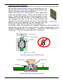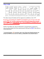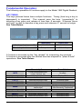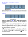
1
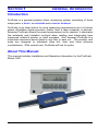
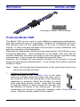
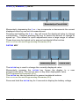
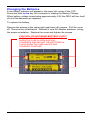
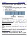
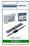
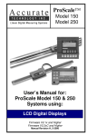
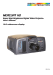
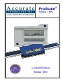
ProScale
Model 18W
Limited Edition
Model 18W
®
WARRANTY
Accurate Technology, Inc. warrants the ProScale Model 18W against
defective parts and workmanship for 1 year commencing from the date of
original purchase. Upon notification of a defect, Accurate Technology, Inc.,
shall have the option to repair or replace any defective part. Such services
shall be the customer's sole and exclusive remedy. Expenses incidental to
repair, maintenance, or replacement under warranty, including those for labor
and material, shall be borne by Accurate Technology, Inc. (Including freight
or transportation charges during the first 30 days).
Except as expressly provided in this warranty, Accurate Technology, Inc.
does not make any warranties with respect to the product, either expressed
or implied, including implied warranties of merchantability or fitness for a
particular purpose, except as expressly provided in this agreement.
Accurate Technology, Inc. shall not be liable for any special, incidental, or
consequential damages or for loss, damage or expense directly or indirectly
arising from the customer's use of or inability to use the equipment either
separately or in combination with other equipment, or for personal injury or
loss or destruction of other property, or from any other cause.
To request repair work, (either warranty qualified parts or not) contact
Accurate Technology, Inc. directly by phone, fax, or e-mail. A Returned
Merchandise Authorization (RMA) number is required before returning a
product for repair.
Accurate Technology, Inc.
+1 828.654.7920
www.proscale.com
800.233.0580 828.654.8824 (F)
[email protected]
SAFETY WARNING
Before installing ProScale on any machinery:
Turn off machine and disconnect power.
SAFETY WARNING
Manual P/N 800-1405-001, Rev A
Copyright © 2009, Accurate Technology, Inc. All rights reserved.
Manual Part # 800-1405-001, Rev A
Page 2 of 20
Table of Contents
SECTION 1
GENERAL INFORMATION..................................................4
INTRODUCTION............................................................................................4
ABOUT THIS MANUAL...................................................................................4
SPECIFICATIONS .........................................................................................4
SPECIFICATIONS .........................................................................................5
ABOUT PROSCALE ......................................................................................6
Scale.....................................................................................................6
Encoder.................................................................................................6
Digital Readout ......................................................................................6
SECTION 2
INSTALLATION...................................................................7
PROSCALE MODEL 18W ..............................................................................7
SECTION 3
DIGITAL READOUT ............................................................9
MOUNTING .................................................................................................9
THE LCD .................................................................................................10
FUNDAMENTAL OPERATION ........................................................................11
KEY TIMING ........................................................................................11
KEY FUNCTIONS FOR STANDARD OPERATION ................................................12
ON/OFF KEY .......................................................................................12
UNITS KEY .........................................................................................12
PLUS (+) & MINUS (–) KEYS..................................................................13
DATUM KEY .......................................................................................13
BASIC FUNCTIONS .....................................................................................14
MEASUREMENT READING DIRECTION .....................................................14
KEY LOCK ..........................................................................................14
DISPLAY RESOLUTION ..........................................................................14
CHANGING THE BATTERY ...........................................................................15
CIRCUIT BOARD JUMPERS ..........................................................................16
SECTION 4
PROGRAMMING ...............................................................17
PR 1 – DATUM KEY ...................................................................................18
PR 2 – DIRECTION OF TRAVEL ....................................................................18
PR 3 – KEY LOCKOUT ................................................................................18
PR 4 – DISPLAY RESOLUTION .....................................................................18
PR 5 – MOVEMENT FOR AUTO-ON FUNCTION ...............................................18
FREQUENTLY ASKED QUESTIONS ................................................................19
Accurate Technology ProScale Model 18W
Page 3 of 20
SECTION 1
GENERAL INFORMATION
Introduction
ProScale is a general purpose linear measuring system consisting of three
major parts: a SCALE, an ENCODER and a DIGITAL READOUT.
ProScale is an ideal choice for most measuring requirements up to 8 inches
where affordable digital precision (better than a tape measure) is desired.
Because ProScale shows the exact measurement on its readout, it eliminates
the ambiguity and mistakes involved when reading and interpreting tape
measures, scales & pointer, or shaft encoders. And, because ProScale is a
solid-state electronic device there's very little to wear out. The encoder and
scale are designed to withstand shop dirt, dust, and other airborne
contaminants. With normal care, ProScale will last for years.
About This Manual
This manual includes Installation and Operation information for the ProScale
Model 18W
Manual Part # 800-1405-001, Rev A
Page 4 of 20
Specifications
Measuring Range*:
up to 8 inches
Accuracy:
± .003 inches
Readout Resolution
.1inch
.1mm
or
.01inch .01mm
or
.001inch .01mm
or
1/16, 1/32 or 1/64 inch
Repeatability:
.001inch or .01mm
Readout Range:
+ 999.999 in; + 399 63/64 in; + 9999.99 mm
Operating Power:
Digi Readout
2 AA Alkaline Batteries
Operating Temp:
40 to 110°F
Slew Rate:
60 inches/second
Encoder cable:
120 inch
* PHYSICAL length of the aluminum scale extrusion is approximately 4 inches
longer than the MEASUREMENT range.
Accurate Technology ProScale Model 18W
Page 5 of 20
About ProScale Model 18W
ProScale Model 18W is a Limited Edition 20th Anniversary Model sold
exclusively on www.proscale.com and at Industry Trade shows where
Accurate Technology exhibits.
ProScale Model 18W systems consist of a
READOUT (or DRO).
SCALE,
an
ENCODER
and a
DIGITAL
Scale
DigiScale Model 18W
The scale consists of a series of conductive patterns bonded to an aluminum
extrusion. The Model 18W Scale is .765 inches wide and comes in
measuring lengths up to 8 inches long.
All Scales are approximately 4 inches longer in their physical length than
their measuring range.
Encoder
The ProScale encoder contains electronic circuitry that transmits and
receives signals to and from the scale using a patented technology called
inductive coupling. This data is then sent to the digital readout where it can
be displayed in millimeters, inches, or fractions.
Multiple encoders, each connected to a digital readout, may be used on the
same scale simultaneously.
Model 18W encoders have blue housings
with a 120 inch shielded cable exiting
from one corner. The encoder orientation
on the scale may be reversed to reverse
the direction of the measurement
readings,
or they may be reversed
through programming in the digital
readout.
Digital Readout
ProScale Model 18W uses a special edition white ProScale Digital Readout.
Refer to SECTION 3 of this manual for information about programming,
installation and operation of this readout.
Manual Part # 800-1405-001, Rev A
Page 6 of 20
SECTION 2
INSTALLATION
End view of Model 18W ProScale
ProScale Model 18W
The Model 18W can be used in many different measurement applications,
and with numerous types of equipment. Therefore all installations will be a
little different and it is the responsibility of the user to choose the bolts,
screws, or other mounting hardware that provides a quality installation and
optimum operation in their application.
Determine an appropriate mounting location and position for ProScale in your
measuring application. Most installations of the Model 18W will hold the
encoder stationary and allow the scale to pass through the encoder during
measurement. If you choose this installation proceed to Step 1.
However, the ProScale will also operate correctly is the encoder is moved
along the scale during measurements. If you choose this method, proceed
directly to Step 2
Note:
1.
Never drill through the colored portion of the scale at any point over
which the encoder will travel.
Stationary Encoder installation
Attach one end of the Connector Link to the scale
using the included screw and fasten the other end of
the connector link to the moving part of the measuring
application or machine. Attach the encoder to a fixed
point using three screws or bolts. Insure that the scale
is properly aligned to pass through the encoder with
the direction of motion of the moving part. Be sure
connections are secure or inaccurate readings could Connector Link
result. Plug the encoder cable into the readout.
Accurate Technology ProScale Model 18W
Page 7 of 20
2.
Stationary Scale installation
If your application is better suited for the scale to be held stationary and
the encoder moved along it during a measurement, you
should use the Guide Clip to capture the encoder and
move it along the scale (see illustration).
Attach the scale to a fixed point in your application
using the included screw. Place the encoder on the
scale. Attach the guide clip to a moving point in your
application such that the slot on the underside of the
clip engages the post on the top of the encoder and
captures it’s movement along the scale. The guide clip
Guide Clip
should exert some pressure on the encoder over the
full range of travel as the two move as a single unit.
Insure the scale and encoder are properly aligned as the encoder is
moved (the guide clip will compensate for slight misalignment in the
direction perpendicular to movement). Adjust the scale alignment if
necessary. Plug the encoder cable into the readout.
Moving Part
Connector Link
Encoder
Scale
Encoder stationary, Scale moving
M oving part
E ncoder
G uide Clip
S cale
Scale stationary, Encoder moving
Manual Part # 800-1405-001, Rev A
Page 8 of 20
SECTION 3
DIGITAL READOUT
This Section includes information for:
Digital Readout, Model 18W
Part Number: 700-1600-231
Firmware Version P 3xxxx & higher
(Firmware version is displayed on power-up)
Mounting
The Readout may be mounted:
• Using Velcro or Double sided tape
• Drilling out the 3 holes from the inside of the case
• Using any of the six holes on the back of the case which may tapped for
M2 or 4-40 screws.
Accurate Technology ProScale Model 18W
Page 9 of 20
The LCD
The above figure illustrates all the segments available on the LCD
Pressing and holding the ON/OFF and UNITS key for 10 seconds with
power OFF will perform a full segment LCD test, display the current
firmware version, AND RESET ALL PROGRAMMING PARAMETERS TO
FACTORY DEFAULT VALUES.
NOTE: The DRO may also be defaulted to original factory settings by
removing the battery and then pressing and holding the UNITS key while reinserting battery. *
* Internal jumper JP3 must be set to the Program Enable position to
allow the DRO to be reset to factory defaults as described above.
Manual Part # 800-1405-001, Rev A
Page 10 of 20
Fundamental Operation
The following operations & functions apply to the Model 18W Digital Readout.
KEY TIMING
The keys pictured below have multiple functions. Timing (how long a key is
depressed) is important. This manual uses the term “momentarily” to
describe a key press and release of less than .8 seconds. Whereas “press
and hold” is used to describe a key press and release of 1 second or longer.
See Table Below:
Momentarily
Press & Hold
How long a key is pressed?
Less than .8 seconds
More than 1 second
When is key function executed?
On key release
While holding
A function is executed on the “key release” for momentary key presses.
A function is executed after the allotted time has elapsed for “press & hold”
operations. See Table Below:
Momentarily Press
Cycles measurement units:
inches, fractions, mm
Press & Hold
(in programming mode)
Increments program parameter list
Displays Pr #
Plus (+)
(in programming mode)
increments displayed value
increments parameter value
increments faster
increments faster
(in programming mode)
forces reading to programmed
datum value
forces parameter to factory default
After 6 seconds: battery voltage
After 9 seconds: Temperature
no effect
Minus (-)
(in programming mode)
decrements displayed value
decrements parameter value
decrements faster
decrements faster
UNITS
Datum
Accurate Technology ProScale Model 18W
No effect
Page 11 of 20
Key Functions for standard operation
ON/OFF KEY
Momentarily press
Momentarily press the ON/OFF key to turn DRO off then momentarily press it
again to turn it back on. The Firmware version is displayed for two seconds
at power-on.
UNITS KEY
Momentarily press
Momentarily depressing the UNITS key will display measurement/position
information in inches, fractions or millimeters . With each key press, the
DRO will cycle through decimal inches, fractions (16ths, 32nds, 64ths) and
millimeters.
When the DRO is in 1/16 or 1/32 inch fraction mode, a series of “bars” in the
upper right corner of the LCD, each representing 1/64th of an inch, may
appear. (ie. When in 1/16 inch mode and three bars are showing, the
measurement displayed is rounded down to the closest 1/16 inch and each
illuminated bar indicates an additional 1/64 of an inch of additional
measurement.) For better resolution, switch to 1/32 or 1/64 mode. For the
best resolution switch to a decimal mode.
When the measurement is greater than 99 63/64 inches, a +100 and/or
+200 will illuminate in the upper right portion of the display to indicate this
amount must be added to the displayed reading. ie: If the measurement is
154 5/8 inches, 54 5/8 and +100 will be illuminated on the display. If the
measurement is -307 23/64 inches, - 7 23/64, +100 and +200 will be
illuminated on the display.
Manual Part # 800-1405-001, Rev A
Page 12 of 20
PLUS
(+) & MINUS (–) KEYS
Momentarily or Press & Hold
Momentarily depressing the + or – key increments or decrements the current
displayed value by one unit of measurement.
Pressing and holding the + or – key will cause the displayed value to change
continuously. Continue pressing the key to cause the amount of change to
speed up. This allows for quick adjustments over a large range of values.
These keys may be locked out to prevent accidental offset entries.
See LOCK FUNCTION and Programming Parameter (Pr3).
DATUM KEY
Momentarily press
Press & Hold
The DATUM key is used to change the currently displayed value.
Momentarily pressing the DATUM key forces the display to a user
programmed value. This can be zero or any other displayable value.
See Programming Parameter (Pr1).
The DATUM key can be locked out to prevent accidental entries.
See LOCK FUNCTION and Programming Parameter (Pr3).
Press and hold the DATUM key for 6 seconds to display the battery voltage.
Accurate Technology ProScale Model 18W
Page 13 of 20
Basic Functions
MEASUREMENT READING DIRECTION
Once the system has been put into operation, if the direction of readings,
(positive or negative values) is opposite the desired direction, the DRO
programming may be changed to correct the direction.
See Programming Parameter (Pr2).
KEY LOCK
The Digital Readout provides a function that can be used to “lock-out” the
position offset adjustment keys (+, DATUM , –) to prevent accidental changes
of the current displayed value. To activate the Lock function, press and hold
the ON/ OFF key and then momentarily press the UNITS key. The word LOCK
will be displayed in the upper left corner of the LCD.
When the LOCK symbol is displayed, the +, DATUM and
– keys become inactive.
To de-activate the Lock function, press and hold the
ON/OFF key and then momentarily press the UNITS key.
The Lock function can also be enabled through programming. This allows a
more permanent Lock function since programming can be disabled with a
hardware jumper inside the DRO. See Programming Parameter (Pr3)
DISPLAY RESOLUTION
Four display resolutions are available with the Model 18W Readout.
.1in
.1mm
or
.01in .01mm
or
.001in .01mm
or
To change to another display resolution See Programming Parameter (Pr4)
Allowable ranges are:
Inch Resolution
3 decimal places
2 decimal places
1 decimal place
Maximum Value (Inches)
Millimeter Resolution
2 decimal places
1 decimal place
Maximum Value (mm)
Manual Part # 800-1405-001, Rev A
999.999
9999.99
99999.9
9999.99
99999.9
Page 14 of 20
Changing the Batteries
A low battery indicator will appear in the lower left corner of the LCD.
Press and hold DATUM key for 6 seconds to display the Battery Voltage.
When battery voltage drops below approximately 2.6V the DRO will turn itself
off until the batteries are replaced.
To replace the battery:
Remove the screws in the upper right and lower left corners. Pull the cover
off. Remove the old batteries. Reinstall 2 new AA Alkaline batteries, noting
the proper orientation. Replace the cover and tighten the screws.
CAUTION: DO NOT BEND BATTERY CLIPS!
THESE CLIPS ARE DESIGNED TO BE LOOSE
WHEN THE CASE IS OPEN AND WILL
COMPRESS AND SECURE THE BATTERIES IN
PLACE WHEN THE CASE HALVES ARE
SCREWED TOGETHER.
Accurate Technology ProScale Model 18W
Page 15 of 20
Circuit Board Jumpers
JP1
FACTORY USE ONLY
JP2
FACTORY CONFIGURED: DO NOT CHANGE
JP3
Programming Lock-out
Default = Position A
Front panel programming of the Digital Readout can be enabled or disabled
though the use of this circuit board jumper.
Front panel Programming is enabled when the shorting jumper is installed in
position A. To disable Programming, install jumper on position B.
When programming is disabled, user cannot access the programming
functions via the front panel as described in: PROGRAMMING PARAMETERS. This
provides a method of configuring the Digital Readout with specific
parameters then preventing unauthorized or accidental configuration
changes.
JP4
FACTORY CONFIGURED: DO NOT CHANGE
JP5
FACTORY CONFIGURED: DO NOT CHANGE
JP3
JP4
JP2
JP5
DRO Circuit Board
Manual Part # 800-1405-001, Rev A
Page 16 of 20
SECTION 4
PROGRAMMING
Several functions of the Readouts are user programmable. The following
section describes how to change factory defaults to customize your DRO.
To enter Programming Mode:
1. Press and hold the UNITS key then momentarily press the DATUM key.
2. The LCD will briefly display: PG on (Programming On), then
Pr 1,
1 (indicating Programming Parameter #1)
3. Release the UNITS key
4. The value stored for Pr1 is displayed.
Press & Hold
Momentarily press
Once in the Programming Mode:
Moving up parameter list - Momentarily press the UNITS key to advance
through the Programming Parameter list, first displaying the Programming
Parameter number then the currently programmed value.
Moving down parameter list - Press and hold the ON/ OFF key and
momentarily press the UNITS key to move backward through the
Programming Parameter list.
Increase parameter value
displaying a Programming
setting.
Decrease parameter value
displaying a Programming
setting.
- Momentarily press the PLUS (+) key while
Parameter Value to increase the parameter
- Momentarily press the MINUS (-) key while
Parameter Value to decrease the parameter
Reset parameter value to default setting - Momentarily press the DATUM key
while displaying a Programming Parameter Value to reset the parameter to
the factory default value.
Exit programming mode - Press and hold the UNITS key. Momentarily
depress the DATUM key. The LCD will briefly display: PG oFF
(Programming Off), then return to normal operation. NOTE: The system will
automatically exit programming mode after 60 seconds of no key activity.
Accurate Technology ProScale Model 18W
Page 17 of 20
The Digital Readout Programming Parameters are listed below.
Values in [ ] are the range of values available for that Parameter.
Factory defaults values are shown in Bold Red.
Pr 1 – Datum Key
[0 to + 999.999in] or [0 to +9999.99mm]
The programmed value that will be recalled whenever the Datum key is
pressed during normal operation.
Default = 0.00
Pr 2 – Direction of Travel
[0 or 1]
This parameter controls the sign of travel (positive vs. negative) when the
measuring system is moved.
Default = 0
Pr 3 – Key Lockout
[0 or 1]
This parameter controls the operation of the +, - and DATUM keys. If enabled,
(set to 1), these keys will not function and the LOCK symbol will appear on the
display. This prevents accidental changes when depressing these keys
during normal operation.
Default = 0
Pr 4 – Display Resolution
[1, 2, 3 ]
This parameter sets the number of places to the right of the decimal point on
the display. When the DRO is in a decimal mode (in, mm or cm), it will autorange to the next resolution if the value is too large to be displayed in the
current resolution but is displayable in an alternate resolution.
A value of 1 will display x.x.
A value of 2 will display x.xx
A value of 3 will display x.xxx
Default = 3
• This programming option has no effect when displaying fractions.
Pr 5 – Movement for Auto-On function
[0.3 to 10mm]
This parameter sets the amount of encoder, or system, movement required
to automatically wake up the digital readout when it is turned off.
Default = 0.1mm
Manual Part # 800-1405-001, Rev A
Page 18 of 20
Frequently Asked Questions
Can I mount the Scale/Encoder without the connector link/guide clip?
Yes. However, the connector link and guide clip serve to provide an
accurate method of transferring the movement of the encoder or
scale, while also absorbing any stresses that may occur. If they are
not used, your system could be damaged and the warranty could
be voided.
What does no Enc mean?
If the encoder is off the scale, or unplugged from the readout,
a no Enc will appear on the readout. To clear the error:
1. Be sure the encoder is on the scale.
2. Plug the encoder into the readout.
3. Unplug the encoder from the readout for one second then
reconnect it.
What does b FAIL mean?
When the readout displays this message it means the battery voltage
has dropped to a level where reliable operation is no longer possible.
Install new batteries to clear this message.
What does P FAIL mean?
When the readout displays this message it means the battery voltage
has dropped to a level where reliable programming is not possible.
Install new batteries to clear this message.
How do I calibrate my ProScale?
There is no calibration available or necessary for the ProScale.
System accuracy will depend on the accuracy of the ProScale Scale
itself and the quality of the installation.
Accurate Technology ProScale Model 18W
Page 19 of 20
Thank you for choosing an
AMERICAN MADE PRODUCT
Accurate Technology, Inc.
270 Rutledge Rd. Unit E
Fletcher, NC 28732 USA
828.654.7920
Please register your product at:
http://www.proscale.com/registration.htm
This manual is available online at:
www.proscale.com
Part # 800-1405-001, Rev A
Copyright © 2010 Accurate Technology, Inc. All rights reserved.
Manual Part # 800-1405-001, Rev A
Page 20 of 20