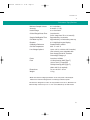
1
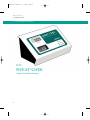
2005-02-11
17:27
Page i
SWEAT• CHEK™
SWEAT CONDUCTIVITY ANALYZER
op
y
Model 3120
Instruction/Service Manual
M2672-2A
C
M2672-2A
i
M2672-2A
2005-02-11
17:27
Page ii
© 2005 Wescor, Inc. All rights reserved. Printed in
the United States of America.
Wescor, Macroduct, Sweat-Chek, Webster Sweat
Inducer and Calibrator are trademarks of Wescor,
Inc. Other trade names used in this manual may
be trademarks of their respective owners, used
here for information only.
U.S. Patent Numbers 4,383,529; 4,542,751. U.K.
Patent Number 2,116,850. German Patent (DBP)
33 09 273.
All information in this manual is subject to change
without prior notice.
ii
M2672-2A
2005-02-11
17:27
Page iii
section
1
INTRODUCTION
1.1
1.2
1.3
1.4
Instrument Description . . .
Customer Service . . . . .
Controls and Connections .
Important User Information.
.
.
.
.
.
.
.
.
.
.
.
.
3
4
5
6
. . . . . . . . . . . . . . . . . . . . . . . . .
9
11
13
14
.
.
.
.
.
.
.
.
.
.
.
.
.
.
.
.
.
.
.
.
.
.
.
.
.
.
.
.
.
.
.
.
.
.
.
.
.
.
.
.
.
.
.
.
.
.
.
.
.
.
.
.
.
.
.
.
.
.
.
.
.
.
.
.
.
.
.
.
.
.
.
.
.
.
.
.
.
.
.
.
.
.
.
.
.
.
.
.
.
.
.
.
.
.
.
.
section
2
OPERATING SWEAT•CHEK
2.1
2.2
2.3
2.4
Instrument Preparation . . . .
Sweat Analysis . . . . . . . .
Cleaning the Conductivity Cell .
System Operating Checks . . .
. . . . . . . . . . . . . . . . . . . . . . . . .
. . . . . . . . . . . . . . . . . . . . . . . . .
. . . . . . . . . . . . . . . . . . . . . . . . .
section
3
INTERPRETATION OF RESULTS
3.1
3.2
3.3
3.4
3.5
3.6
Background . . . . . . . . . . . . . . . . . . .
Units of Measurement and Clinical Ranges . . .
Conductivity and the CAP Survey Program . . .
Conductivity in the Diagnostic Analysis of Sweat .
Reportable Range and Its Justification . . . . . .
References . . . . . . . . . . . . . . . . . . .
. . . . . . . . . . . . . . . .
. . . . . . . . . . . . . . . .
. . . . . . . . . . . . . . . .
. . . . . . . . . . . . . . . .
. . . . . . . . . . . . . . . .
. . . . . . . . . . . . . . . .
17
19
21
23
25
26
section
4
TROUBLESHOOTING AND SERVICE
4.1 Troubleshooting and Service Overview
4.2 Instrument Calibration . . . . . . . . .
4.3 Replacing the Conductivity Cell . . . .
. . . . . . . . . . . . . . . . . . . . .
29
30
33
. . . . . . . . . . . . . . . . . . . . . . . . . . . . . .
37
. . . . . . . . . . . . . . . . . . . . .
. . . . . . . . . . . . . . . . . . . . .
APPENDIX A
Instrument Specifications .
APPENDIX B
Accessories, Supplies, and Replacement Parts
. . . . . . . . . . . . . . . . . . .
41
. . . . . . . . . . . . . . . . . . . . . . . . . . . .
45
. . . . . . . . . . . . . . . . . . . . . . . . . . . . . . . . . . . . . . .
49
APPENDIX C
Changing the Voltage Selector
INDEX
iii
M2672-2A
iv
2005-02-11
17:27
Page iv
M2672-2A
2005-02-11
17:27
Page 1
S E C T I O N
1
INTRODUCTION
1
M2672-2A
2005-02-11
S E C T I O N
17:28
Page 2
1
INTRODUCTION
1.1 Instrument Description
3120
SWEAT• CHEK
Sweat Conductivity Analyzer
2
M2672-2A
2005-02-11
17:28
Page 3
S E C T I O N
1
INTRODUCTION
1.1 Instrument Description
The 3120 SWEAT•CHEK Sweat Conductivity
Analyzer provides simple and economical sweat
analysis for the laboratory diagnosis of cystic fibrosis. Designed specifically for use with the Wescor
Macroduct® Sweat Collector, it can measure the
electrolyte concentration of a sweat specimen as
small as 6 to 10 microliters.
The Analyzer’s flow-through conductivity cell operates at a precisely controlled temperature for
improved stability and accuracy. In keeping with
established practice, the readout on the digital display is calibrated in mmol/L (equivalent NaCl). The
reading obtained represents the molar concentration of sodium chloride in aqueous solution that
would exhibit, at the sample temperature, the
observed sample conductivity.
The conductivity cell is located beneath a recessed
cover on the front panel of the instrument, just
below the digital display. In the recess of this cover,
two short 0.76 mm diameter stainless steel nipples
serve as inlet and outlet connections to the cell.
For measurement, two short lengths of microbore
plastic tubing are slipped over the stainless steel
nipples. One of these tubes is from the Macroduct
sweat collector and contains the sweat specimen to
be analyzed. The other tube serves as the “takeup” tube. During analysis, the sweat specimen is
transferred from the Macroduct tube into the takeup tube via the conductivity cell. After the sweat
specimen is transferred into the cell, its electrical
conductivity is measured, the electrolyte concentration is calculated, and the result appears on the
digital display.
Complete instructions for this procedure are found
in Section 2.
3
M2672-2A
2005-02-11
S E C T I O N
17:28
Page 4
1
INTRODUCTION
1.2 Customer Service
Wescor is ready to help you resolve any problems with your SWEAT•CHEK
Analyzer. If you cannot solve a problem using the procedures in this manual
please contact us.
Customers within the United States and Canada are encouraged to contact us
by telephone. Outside the U.S., many of our authorized dealers offer complete
customer service and support. Contact Wescor by mail, telephone, fax or email at the address and numbers listed below.
Wescor, Inc
459 South Main Street
Logan, Utah 84321-5294
USA
TELEPHONE:
(435) 752 6011
TOLL FREE:
(800) 453 2725 (U.S. and Canada)
FAX:
(435) 752 4127
E-MAIL:
[email protected]
WEBSITE:
www.wescor.com
NOTE:
Wescor’s Authorized European Representative for matters relating to the Medical Device Directive is:
MT Promedt Consulting GmbH
Altenhofstraße 80
D-66386 St. Ingbert, Germany
Tel: +49 6894 581020
Fax: +49 6894 581021
email: [email protected]
www.mt.procons.com
4
M2672-2A
2005-02-11
17:28
Page 5
S E C T I O N
1
INTRODUCTION
1.3 Controls and Connections
DIGITAL DISPLAY
INSTRUMENT FRONT
INLET/OUTLET NIPPLES
WAIT INDICATOR
READY INDICATOR
CONDUCTIVITY CELL
POWER INDICATOR
INSTRUMENT REAR
CALIBRATING TOOL
MODEL AND SERIAL NUMBER
POWER CORD
RECEPTACLE
POWER SWITCH
CALIBRATION PORT
POWER ENTRY MODULE
The power switch is located on the back of the instrument as part of the Power Entry
Module. When connected to the proper line voltage and turned ON (I) the power indicator should glow GREEN.
5
M2672-2A
2005-02-11
S E C T I O N
17:28
Page 6
1
INTRODUCTION
1.4 Important User Information
SPECIFICATION OF SAFE USE:
Using this instrument in a manner not specified by Wescor
may impair the safety protection designed into the equipment and may lead to injury.
SAFE USE ENVIRONMENT:
This device has been designed for indoor use only, between
5 and 40 °C, maximum relative humidity 80%, at up to 31
°C. For use at altitudes up to 2000 meters.
FUSES:
All fuses in this equipment are time-lag (Type T).
For use with a Mains Supply voltage of 85 to 264 Volts AC
@ 50 to 60 Hz, ±10%.
Transient Overvoltage Category II.
Pollution Degree 2 in accordance with IEC 664.
EXPLANATION OF SYMBOLS FOUND ON EQUIPMENT:
∼ Alternating Current (AC)
I
Power On
O
Power Off
International Attention Symbol.
Calls attention to important information and
instructions in the instruction manual.
6
M2672-2A
2005-02-11
17:28
Page 7
S E C T I O N
2
OPERATING SWEAT•CHEK
7
M2672-2A
8
2005-02-11
17:28
Page 8
M2672-2A
2005-02-11
17:28
Page 9
S E C T I O N
2
OPERATING SWEAT•CHEK
2.1 Instrument Preparation
1
The power switch is located on the back panel in the
power entry module. Make certain the switch is OFF
(0).
2
Plug the female end of the power cord into the power
entry module. Note the voltage indicator window. If the
voltage does not match the voltage of your power outlet, refer to Appendix C before proceeding.
NOTE:
We recommend using a grounded power line surge protector to isolate
the instrument from spikes and surges.
3
Plug the male end of the power cord into a grounded
power outlet.
4
Turn the power switch on (I). The power indicator should
glow GREEN. The display will read zero:
The WAIT indicator glows amber. Within two minutes,
it will switch off and the READY indicator will glow
green, indicating that the conductivity cell has stabilized at the correct operating temperature. The
Analyzer is now ready to accept samples.
9
M2672-2A
2005-02-11
S E C T I O N
17:28
Page 10
2
OPERATING SWEAT•CHEK
2.1 Instrument Preparation
10
5
Attach a length of clean microbore tubing (SS044) to serve as the outlet tube to one of the
stainless steel nipples. While either nipple can
be used, we suggest that the right hand nipple
be used as the outlet.
6
Check calibration before introducing specimen,
(see Section 2.4). After calibration (if needed),
clean and dry the cell before proceeding with
analysis, (see Section 2.3).
7
Attach the tube containing the specimen for
analysis to the opposite (we recommend the
left) nipple, which will serve as the inlet. See
Section 2.2 for complete instructions.
M2672-2A
2005-02-11
17:28
Page 11
S E C T I O N
2
OPERATING SWEAT•CHEK
2.2 Sweat Analysis
The Macroduct Sweat Collection System manual provides
complete instructions for sweat collection. These should
be followed rigorously.
Normally, the sweat specimen is introduced directly into
the conductivity cell from the Macroduct collection tube. A
typical Macroduct sweat collection produces many times
the sweat volume needed for analysis. In cases where
sweat yield is below average, measurement is possible
using 6 to 10 microliters of sweat; but careful and precise
technique is mandatory, since positioning of the sample
within the cell becomes critical.
If the sample volume is insufficient to establish continuity
between the electrodes in the conductivity cell (approximately 6 microliters), no measurement will be possible.
However, any reading sustained on the digital display for
at least a few seconds will be valid.
PREVIOUSLY COLLECTED SWEAT OR SWEAT CONTROLS
If the sweat specimen has been transferred to a storage
cup, or if you wish to inject Calibrator solution (SS-140),
sweat control solutions (SS-150), or water into the
Analyzer, simply attach a spare take-up tube to the
syringe. Position the syringe plunger near mid-point, and
carefully withdraw the plunger to bring the specimen into
the tube. Use only new, clean tubing that is certified
solute-free to avoid measurement errors (tubing supplied
by Wescor meets this requirement). Do not aspirate liquid into the syringe body.
NOTE:
Handle the sweat specimen with care before analysis to avoid
introducing air bubbles into the sweat column. An air bubble in the
conductivity cell will prevent measurement.
the end of the specimen tube to the inlet nip1 Connect
ple of the conductivity cell (we suggest the left hand
nipple). Push tubing “straight on” the nipple.
11
M2672-2A
2005-02-11
S E C T I O N
17:29
Page 12
2
OPERATING SWEAT•CHEK
2.2 Sweat Analysis
CAUTION!
Push the tubing STRAIGHT ON to the stainless steel
nipples without bending them. Repeated bending will
eventually cause the nipple to fracture, requiring
replacement of the conductivity cell.
the specimen into the cell by gently moving
2 Transfer
the syringe plunger into its barrel. When the liquid
column of the specimen makes contact with the cell
electrodes, the digital display will rise quickly from its
zero reading. Stop injecting the sample at this point,
and the sample will rapidly equilibrate to the cell temperature.
Moving the liquid column brings cooler liquid into the
conductivity cell, briefly producing a lower reading,
but the reading quickly stabilizes when motion ceases. In large samples, a slight beginning-to-end conductivity variation is normal. See Section 3.2 to interpret readings.
the liquid column of the specimen loses con3 When
tact with the first cell electrode, the reading will fall to
zero.
desired, the specimen can be drawn back into the
4 Ifcell
to repeat the measurement. If the plunger is
moved smoothly and gently, the specimen can be
transferred in and out of the conductivity cell for as
many measurements as desired. Abrupt, jerky movements of the plunger can separate the liquid column,
and the resulting air bubbles will interrupt readings
as they pass through the cell.
clean and dry the conductivity cell using the
5 Thoroughly
instructions in Section 2.3.
12
M2672-2A
2005-02-11
17:29
Page 13
S E C T I O N
2
OPERATING SWEAT•CHEK
2.3 Cleaning the Conductivity Cell
1
After testing each specimen, rinse the conductivity cell with at least one full take-up tube of
deionized water.
2
When all residual salt has been flushed from the
cell, the reading on the display reads “000” (with
pure water in the cell).
3
Remove water by using the syringe to push air
through the cell. After all discernible liquid has
been flushed, remove the take-up tube and
“pump” the syringe to blow out any remaining
micro droplets and dry the cell. Finally, push the
syringe plunger completely down to purge
remaining droplets of water from the cell. This
procedure is necessary to ensure accuracy of
any subsequent measurement.
CAUTION!
Never allow any liquid to remain in the conductivity
cell after measurements are complete. Besides risking
a measurement artifact in the next procedure, the
instrument can be damaged if it is inadvertently
exposed to freezing temperatures such as could occur
during transport to a testing site in cold weather. To
avoid damage to the cell or other sensitive electronic
components, do not expose the instrument to extremes of heat or cold.
13
M2672-2A
2005-02-11
S E C T I O N
17:29
Page 14
2
OPERATING SWEAT•CHEK
2.4 System Operating Checks
SWEAT•CHEK is factory-calibrated and under normal conditions
should not require further adjustment. IF THE CELL IS CLEAN AND
FREE OF RESIDUAL SALT OR WATER, calibration of the instrument can be checked using a freshly opened NaCl standard solution such as that initially supplied with the instrument. The reading
given by the Analyzer should agree with the specified molarity of the
standard solution within ± 2 mmol/L. If recalibration becomes necessary refer to Section 4.2.
SWEAT•CHEK has an extremely stable response characteristic
that is virtually linear through the critical range from 75 to 110
mmol/L. At extremely low ranges, there will be a slight positive
error in the reading, and at extremely high ranges, a slight negative error. These errors will not invalidate the diagnostic result.
See Section 3.5.
Check calibration to ascertain that the temperature of the cell is
within the correct range and that the electronics are otherwise
functioning normally. A reading that agrees with the labeled
value of the standard solution indicates correct overall performance to a very high level of confidence. Further testing is not
normally necessary.
Sweat Controls
Normal
Appr. 40 mmol/L
High Normal/Equivocal
Appr. 70 mmol/L
If you require a CF-positive and/or CF-negative control value,
Wescor Sweat Controls (SS-150) provide three levels of control
for validating measurements of electrolyte concentration as
shown at left:
Abnormal
Appr. 130 mmol/L
CAUTION!
Push the tubing STRAIGHT ON to the stainless steel nipples without
bending them. Repeated bending will eventually cause the nipple to
fracture, requiring replacement of the conductivity cell.
14
M2672-2A
2005-02-11
17:29
Page 15
S E C T I O N
3
INTERPRETATION OF RESULTS
15
M2672-2A
16
2005-02-11
17:29
Page 16
M2672-2A
2005-02-11
17:29
Page 17
S E C T I O N
3
INTERPRETATION OF RESULTS
3.1 Background
Children afflicted with cystic fibrosis (CF) clearly show
elevated electrolyte concentrations in their sweat, compared with the sweat of children unaffected by this disease.1,2 With increasing age, however, the difference
between normal and abnormal sweat electrolyte levels
becomes less distinct; thus, the borderline and low
abnormal results commonly encountered in adults are
not indicative of disease. A diagnosis of CF will always
be based upon clinical findings and observations, but
the “laboratory diagnosis” or “sweat test,” performed
properly, provides valuable quantitative corroboration of
the physician’s clinical diagnosis.
Historically, the “sweat test” was performed without
Macroduct and SWEAT•CHEK and has shown a high
incidence of both false positive and false negative
results, with false positives predominating. The professional literature3,4,5 has been highly critical of various
commercial systems that purport to simplify one or
more of the three steps in the procedure, i.e. SWEAT
INDUCTION, SWEAT COLLECTION and SWEAT
ANALYSIS. Most of the errors involved the collection
phase of the test. Webster’s comprehensive review of
quantitative sweat testing, from the early 1950’s through
1983, identified error factors associated with each of
these methods.6
Although numerous sweat testing systems have been
marketed, the Cystic Fibrosis Foundation of America
has approved only two methods of sweat collection.
They are the original pad absorption method of Gibson
and Cooke7 and the Wescor Macroduct Sweat
Collection System.8,9
The sweat test’s analytical phase was limited to chloride
ion assay in laboratories of the early 1950’s. Today, laboratory technologists can choose from a number of
alternative analytical methods, including anion assay,
cation assay, osmolality, or electrical conductivity. The
SWEAT•CHEK Sweat Conductivity Analyzer measures
the electrolyte concentration of the specimen by electrical conductivity.
17
M2672-2A
2005-02-11
S E C T I O N
17:29
Page 18
3
INTERPRETATION OF RESULTS
3.1 Background
Licht,10 Gibson,11 Phillips,12 Shwachman,13 and others extensively investigated conductivity as an alternative method of
sweat analysis. They concluded that conductivity can be a
reliable laboratory indicator to either rule out or confirm the
clinical diagnosis of cystic fibrosis. See Section 3.4 for more
information on the status of conductivity.
The designs of earlier sweat conductivity measuring instruments were lacking in terms of specimen handling, calibration stability, and measurement resolution. The
SWEAT•CHEK Sweat Conductivity Analyzer, with its temperature-controlled measurement cell, flow-through operation,
and wide-range digital readout, is a modern adaptation of a
proven analytical method. One of the world’s leading authorities on sweat testing, commenting on SWEAT•CHEK stated,
“If this machine is kept clean, it gives results that are every
bit as reliable as an analysis for sodium or chloride.”14
18
M2672-2A
2005-02-11
17:29
Page 19
S E C T I O N
3
INTERPRETATION OF RESULTS
3.2 Units of Measurement and Clinical Ranges
In addition to sodium and chloride ions, sweat also contains significant concentrations of potassium, bicarbonate, and lactate ions. This poses a problem when
selecting a reference or calibration solution, but sodium
chloride solutions serve well if allowance is made for
the other electrolytes. Thus, the reference ranges for
electrolyte concentration in normal and abnormal
groups, in terms of sodium chloride standards, will differ
from those established for specific assay of chloride
ions.
SWEAT•CHEK was evaluated at three separate medical centers in studies of 514 patients, among whom
were 43 clinically confirmed cases of cystic fibrosis.15
Analysis of the combined data is shown on the following
page (Table 3-1).
The normal, borderline and abnormal electrolyte concentration ranges were established by reference to the
data published by Hammond et.al.15, using their equation relating electrolyte concentration to chloride:
ELECTROLYTE CONCENTRATION (USING SWEATCHEK)
Normal
0-60
Borderline
60-80
Abnormal
80+
(mmol/L)
CHLORIDE
Normal
0-40
Borderline
40-60
Abnormal
60+
(mmol/L)
Readings on Sweat-Chek classified and
compared to chloride analysis.
Bias = Electrolyte Concentration (conductivity) - Chloride
The bias (unmeasured anions) was observed to be a
function of the conductivity value, and this enabled converting chloride range-limiting levels of 40 to 60 mmol/L
to their electrolyte conductivity equivalents shown in the
accompanying table.
Carefully assess any result in the “borderline” region
between 60 and 80 mmol/L. Factors such as age, state
of hydration, family history of CF, etc., must be
assessed by the attending physician, together with the
sweat analytical data. Retesting, along with alternative
methods of analysis, such as chloride or sodium ion
assay, may help resolve an equivocal sweat test result.
It has been shown that the concentration of electrolytes
decreases as sweating continues in time.11 If the sweat
yield during collection is 30 microliters or more (typical
yield is 50 to 60 microliters in 30 minutes using
Macroduct), then an increase in the reading may be
observed as the sweat column passes from the
Macroduct collection tube through the conductivity cell
into the “take-up” tube. The variation will be small in
comparison with the difference between normal and
abnormal sweat, and thus will not confound the diagnosis.
19
M2672-2A
2005-02-11
S E C T I O N
17:29
Page 20
3
INTERPRETATION OF RESULTS
3.2 Units of Measurement and Clinical Ranges
Among the patient populations mentioned above, data on chloride
ion assay and sodium plus potassium ion assay, determined simultaneously with the conductivity data, enables linear regression
analysis:
Chloride Ion Concentration
VS.
Sweat Conductivity
n = 514 r = 0.974
Cl¯ = 0.96 (C) -15.21
Sodium + Potassium Ion Concentration
VS.
Sweat Conductivity
n = 514 r = 0.987
Na+ + K+ = 0.974 (C) - 1.49
C = (electrolyte concentration equivalent NaCl mmol/L)
Table 3-1
CLINICAL RANGES
SWEAT CONDUCTIVITY AS EQUIVALENT NaCl (mmol/L)
Number of Patients
Mean Value
Standard Deviation
Observed Range
20
Non CF
CF
471
33.4
11.2
13-87
43
113.1
9.9
90-136
M2672-2A
2005-02-11
17:29
Page 21
S E C T I O N
3
INTERPRETATION OF RESULTS
3.3 Conductivity and the CAP Survey Program
The readout in mmol/L (equivalent NaCl) means that the sweat
sample has a conductivity equivalent to that of a NaCl solution
of the displayed mmol/L concentration (at the same temperature).
This reading DOES NOT represent the actual concentration
of either sodium or chloride in the sweat.
The level of electrical conductivity is a direct function of the concentration of ionized molecules in a solution. Sweat samples
are made up of sodium, potassium, and a small amount of
ammonium, as the cation contribution. The anions balancing
these are mainly chloride, with lactate and bicarbonate. Thus,
the conductivity can be seen as a measure of the total electrolyte concentration in mmol/L. The electrolyte selected for calibration reference is sodium chloride but it could be any other
salt. The chemical nature of the calibration solution is immaterial, because the reference ranges for sweat conductivity will be
based upon comparison with the calibration value, and will be
valid whatever electrolyte is used as a reference.
Conductivity in the CAP Sweat Survey Program
Regrettably, in the CAP Survey Program, some Sweat-Chek
users continue to present their sweat conductivity results in
the survey section meant for those labs that specifically measure chloride by one method or another.
Prior to 1997, when the CAP samples were pure NaCl solutions, this practice did not lead to a problem in terms of numerical value of conductivity as compared with the chloride value
because the sample only contained NaCl. However, when laboratories were asked to make diagnostic judgments on the basis
of their results, it did create a serious problem for those mistakenly submitting conductivity as chloride. These laboratories did
not appear to recognize that by submitting their data to the
chloride section their results would be assessed in terms of
the accepted diagnostic ranges for chloride. Since conductivity
ranges are different from chloride ranges due to the presence of
significant amounts of non-chloride ions in sweat, this usually
resulted in an apparent misdiagnosis as far as the CAP Survey
was concerned.
21
M2672-2A
2005-02-11
S E C T I O N
17:29
Page 22
3
INTERPRETATION OF RESULTS
3.3 Conductivity and the CAP Survey Program
For example, a laboratory finding a conductivity result of 70
mmol/L (equiv. NaCl) would judge this as an equivocal result
in terms of the recommended diagnostic ranges for conductivity
based on clinical trials. If it had been properly presented to the
conductivity section of the Survey, it would be correctly
judged by its peer group (conductivity users) as equivocal.
However, if it were placed in the CAP section meant specifically
for chloride measurers, it would be viewed as a false diagnosis, because a level of 70 mmol/L is a positive result for chloride.
In 1997 the CAP replaced pure NaCl solutions with simulated
sweat samples for analysis in the assessment of laboratory
competence. This was accomplished by the addition, to the
basic NaCl, of a representative quantity of other salts to produce a total electrolyte content similar to sweat in each of the
three diagnostic categories. This was a long awaited and much
welcomed move. However, it must be understood that in all
three simulated sample groups, low, medium, and high in electrolyte content, the chloride content will be, as in sweat, lower
than the total anion content and therefore lower than the conductivity value. For this reason, all conductivity results that are
included in and compared with the data of the chloride-analyzing group of laboratories will apparently be significantly in error.
Consequently, it remains extremely important that those
laboratories that wrongly present conductivity results to
the chloride section must desist from this practice. When
properly included in the conductivity section, the results
will be seen in relation to and compared with those of peer
laboratories.
22
M2672-2A
2005-02-11
17:29
Page 23
S E C T I O N
3
INTERPRETATION OF RESULTS
3.4 Conductivity in the Diagnostic Analysis of Sweat
Recently much confusion has arisen in laboratory departments
after the publication of the recommendations of the National
Committee for Clinical Laboratory Standards, (Sweat Testing
Guideline C34-A) that have been adopted by the Cystic Fibrosis
Foundation of America.
The Foundation did not recognize electrical conductivity as a
diagnostic analytical procedure in sweat testing. Rather, conductivity is relegated to a screening procedure only. Accordingly,
Sweat-Chek is not accepted for use in the Care Centers under
its control.
Until 2000, NCCLS also advised that a patient with a sweat conductivity result of 50 mmol/L or higher should be referred to an
accredited CF care center for a sweat chloride analysis, and on
page 21 of Guideline C34-A (1994) one found the following
statement: “Any sweat conductivity result greater than or equal
to 50 mmol/L (equivalent sodium chloride, NaCl) is considered
positive.” Reference to the Hammond, et. al. sweat data15
shows that 50 mmol/L conductivity is in fact equivalent to 28
mmol/L chloride, a value that does not fall into either the positive or equivocal compass, but is well within the normal range
for chloride. Wescor brought this to the attention of the
Foundation and in the Revised NCCLS Guideline C34-A2 (2000)
the referenced statement had been removed.
The rationale for the Foundation’s position is not readily apparent. If, as it would seem, it stems from their statement that conductivity is to be regarded as only a screening test, there is no
support for this premise in the scientific literature. A thorough
perusal of the Hammond paper fails to reveal any basis for such
an interpretation15, 16. On the contrary, we submit the following
quotation from Shwachman and Mahmoodian in the paper published in 1967:
“The standard conductivity measurement is made immediately after the collection of sweat and provides an instant
answer... The correlation between this measurement and
the electrolyte concentration is excellent and every patient
with cystic fibrosis tested was properly identified. No individuals were falsely diagnosed. The rarely encountered borderline case by one method gives the same borderline
value by the other method.”17
23
M2672-2A
2005-02-11
S E C T I O N
17:29
Page 24
3
INTERPRETATION OF RESULTS
3.4 Conductivity in the Diagnostic Analysis of Sweat
Further, a comparative statistical analysis of the extensive chloride data of Shwachman,17 the Macroduct trial results of various
electrolytes versus conductivity by Hammond, and osmolality
results from Webster clearly shows that conductivity, chloride,
and osmolality are equivalent in their ability to discriminate
between non-CF and CF groups. These statistics were presented in a poster at the 5th International Conference on Neonatal
Screening for Cystic Fibrosis, Caen (France), 1998.18
Finally, a recent large scale study (3834 subjects) has shown
convincing correlation between conductivity and chloride concentration. This study identified conductivity values associated
with normal and CF positive with the normal cutoff being <75
mmol/L and CF diagnosis confirmed at ≥ 90 mmol/L.19
Wescor makes no pretense of authority in setting, determining,
or influencing reference ranges, being content to defer to the
collected research of the medical community. However, an
objective reading of the extant studies on the subject seem to
agree, with some slight variations from study to study, that it is
quite reasonable to assume that the upper limit of normal would
be >70 mmol/L, and that >90mmol/L would be a positive indication for CF. Further, we are confident that the Sweat Chek
Analyzer can accurately indicate a patient’s true sweat conductivity values whatever the accepted and established ranges
might be.
24
M2672-2A
2005-02-11
17:29
Page 25
S E C T I O N
3
INTERPRETATION OF RESULTS
3.5 Reportable Range and its Justification
The following information is provided to help you meet regulatory and
quality requirements:
1. Reportable Range
The reportable range with Sweat-Chek conductivity measurement is 0 to
150 mmol/L, defined as the range of values that have been established
as providing acceptably accurate laboratory results for the intended clinical use.
2. Linearity of Conductivity Versus Electrolyte Concentration
Data produced by Wescor using the Sweat-Chek analyzer is based upon
the calibration of the instrument at one point only: 90 mmol/L (equivalent
NaCl), then recording the readings given by standard NaCl solutions
ranging from 0 to 150 mmol/L. The calibration point of 90 mmol/L was
selected since it coincides approximately with the middle point of the
complete range and with the lowest published values for CF subjects.
The results show that the response is reasonably linear from 20 to 90
mmol/L. The error in this range is relatively constant and represents an
overestimate of the true value by about 2 mmol/L reducing to zero at 90
mmol/L. In the range 90 to 140 mmol/L the error becomes an underestimate that increases regularly from zero at 90 mmol/L to 6 mmol/L below
the true value at 140 mmol/L, (a range that corresponds with the clinically
recorded span of CF values).
3. Justification for Reportable Range
The designation acceptably accurate referred to above is applied for the
following reasons:
For control patients in the normal range (0 to 60 mmol/L) the constant
overestimate (+2 mmol/L) is too small to convert a normal result into a
frankly borderline result.
For borderline patients (60 to 80 mmol/L), the measured value is a constant overestimate, at about 1 to 2 mmol/L and is again much too small
to convert a borderline into a positive result.
For positive (greater than 80 mmol/L), CF subjects, the error is an
underestimate and variable, negligible in the critical range of 80 to 110
mmol/L, and maximal in the upper part of the abnormal range (140
mmol/L) where it cannot in any way effect the diagnosis.
25
M2672-2A
2005-02-11
S E C T I O N
17:29
Page 26
3
INTERPRETATION OF RESULTS
3.6 References
References
1. di Sant’ Agnese, P.A., Darling, R.C., Perera, G.A., Shea, E., Sweat electrolyte disturbances associated
with childhood pancreatic disease. Am J Med, 1953;777-784.
2. Clarke, J.T., Ellian, E., Shwachman, H., Components of sweat. Am J Dis Child 1961;101:490.
3. Gibson, L.E., The decline of the sweat test. Clin Pediatr 1973;12:450.
4. Rosenstein, B.J., Langbaum, T.S., Gordes, E., Brusilow, S.W., Cystic Fibrosis: problems encountered
with sweat testing. JAMA 1978;1987:240.
5. Denning, C.R., Huang, N.N., Cuasay, L.R., Shwachman, H., Tocci, P., Warwick, W.J., Gibson, L.E.,
Cooperative study comparing three methods of performing sweat tests to diagnose cystic fibrosis.
Pediatrics 1980;66:752.
6. Webster, H.L., Laboratory diagnosis of cystic fibrosis. CRC Crit. Rev. in Clin. Lab. Sci. 1983;18:313338.
7. Gibson, L.,E., Cooke, R.E., A test for concentration of electrolytes in sweat in cystic fibrosis of the pancreas utilizing pilocarpine by iontophoresis. Pediatrics 1959;23:545.
8. Barlow, W.K., Webster, H.L., A simplified method of sweat collection for diagnosis of cystic fibrosis. In
Lawson D, ed., Cystic fibrosis: horizons, Proceedings of the 9th International Cystic Fibrosis Congress,
Brighton, England, June 9-15, 1984, New York, NY: John Wiley & Sons, 1984:204.
9. Carter, E.P., Barrett, A.D., Heeley, A.F., Kuzemko, J.A., Improved sweat test method for the diagnosis
of cystic fibrosis. Arch. Dis. Child. 1984;919-922.
10. Licht, T.S., Stern, M., Shwachman, H., Measurement of the electrical conductivity of sweat. Clin Chem
1957;3:37.
11. Gibson, L.E., di Sant’ Agnese, P.A., Studies of salt excretion in sweat. Relationships between rate,
conductivity, and electrolyte composition of sweat from patients with cystic fibrosis and from control subjects. J Pediatr 1963;62: 855.
12. Phillips, W.R., Electrical conductivity of sweat. A simple home-assembled apparatus. Pediatrics
1963;32:89.
13. Shwachman, H., Dunham, R., Phillips, W.R., Electrical conductivity of sweat. A simple diagnostic test
in children. Pediatrics 1963;32:85.
14. Gibson, L.E., Private communication. Rush-Presbyterian-St Luke’s Medical Center, Chicago, IL,
August 1987, January 1988.
15. Hammond, K. B., Turcios, N. L., and Gibson, L. E., Clinical evaluation of the macroduct sweat collection system and conductivity analyzer in the diagnosis of cystic fibrosis. J Pediatrics, 1994;124: 255-260.
16. Van der Merwa, D., Ubbink, J. B., Deelport, R., Becker, P., Dhatt, G. S. Vermaak, W.J.H.: Biological
variation in sweat sodium chloride conductivity. Ann Clin Biochem 2002; 39: 39-43.
17. Shwachman, H., Mahmoodian, A.: Pilocarpine iontophoresis sweat testing. Results of seven years
experience. Bibl. Paediatr. 86:158-182, 1967.
18. Webster, H. L., Sweat conductivity is a valid analysis for cystic fibrosis. Proceedings of the
International Conference of Neonatal Screening for Cystic Fibrosis. Page 101, Caen, France, 1999.
19. Lezana, J. L., Vargas, M. H., Karam-Bechara, J., Aldana, R. S., Furuya, E. Y., Sweat conductivity and
chloride titration for cystic fibrosis in 3834 subjects. Journal of Cystic Fibrosis. 2 (2003) 1-7.
26
M2672-2A
2005-02-11
17:29
Page 27
S E C T I O N
4
TROUBLESHOOTING AND SERVICE
27
M2672-2A
28
2005-02-11
17:29
Page 28
M2672-2A
2005-02-11
17:29
Page 29
S E C T I O N
4
TROUBLESHOOTING AND SERVICE
4.1 Troubleshooting and Service Overview
The SWEAT•CHEK analyzer is designed to be simple to operate and easy to maintain. The following troubleshooting chart provides suggestions to help you quickly solve routine problems
that might be encountered using the SWEAT•CHEK Analyzer. These solutions are indexed to
additional information found in this section.
Aside from replacing the conductivity cell, there are no user-serviceable parts inside the instrument case. The analyzer case should never be opened except by qualified service personnel.
More difficult problems may require detailed technical service. Contact your dealer or Wescor
for assistance. Refer to Section 1.2 for Customer Service information.
START
Blank display, no LED's lit.
Display always reads zero.
Check for power to
instrument, "POWER" switch
in ON position.
No sample or an air bubble
in sample chamber.
Check for proper voltage
selection, blown fuses.
Check for broken or loose
nipple.
Low readings, cool sample
chamber, no "READY" light.
If the above
procedures fail to solve
the problem then
instrument repair is required.
(Section 1.2)
Hot sample chamber,
elevated reading.
Replace sample
chamber and calibrate
instrument.
(Sections 4.2 and 4.3)
* Performed By Qualified Personnel Only
29
M2672-2A
2005-02-11
S E C T I O N
17:29
Page 30
4
TROUBLESHOOTING AND SERVICE
4.2 Instrument Calibration
The instrument must be calibrated if the conductivity cell
has been replaced or if you determine that recalibration
is needed (see System Operating Checks, Section 2.4).
Two common factors can influence the reading, so
before performing recalibration, be sure to check the following:
A. RESIDUAL SALT OR WATER IN THE CONDUCTIVITY
CELL.
If the cell is not rinsed thoroughly after testing sweat or
saline solutions, residual salt may be left in the cell.
This tends to increase the reading on a subsequent
specimen. Rinse water must be purged from the cell
after rinsing, or it may dilute a subsequent specimen,
causing a decreased reading. Make certain the cell is
clean and dry before calibrating or processing samples.
B. CONCENTRATED CHECK SOLUTION
NaCl standard solutions tend to concentrate whenever
the contents are exposed to the atmosphere. If you
doubt the validity of the Calibrator solution, use a freshly-opened ampule before proceeding.
30
M2672-2A
2005-02-11
17:29
Page 31
S E C T I O N
4
TROUBLESHOOTING AND SERVICE
4.2 Instrument Calibration
If you have eliminated the possibility of error from other
sources, and recalibration is indicated, the procedure is
as follows:
CALIBRATOR SOLUTION INTO THE CON1 INJECT
DUCTIVITY CELL.
a. Connect a new tube (Wescor catalog number
SS-044) to the outlet (right) nipple of the cell.
b. Attach a second new tube to the blunt-end needle of the syringe, and draw a specimen directly
from the calibrator ampule into the tube (do not
draw solution into the syringe).
c. Connect the syringe tube to the inlet (left) nipple
of the cell.
d. Gently move the syringe plunger to transfer the
Calibrator solution into the conductivity cell. The
reading will stabilize in approximately 10 seconds.
31
M2672-2A
2005-02-11
S E C T I O N
17:29
Page 32
4
TROUBLESHOOTING AND SERVICE
4.2 Instrument Calibration
CALIBRATION
2 ADJUST
Insert the small end of the calibration tool into the
small calibration port on the left side of the analyzer.
With the tool seated in the small slot in the bottom of
the port, observe the display while rotating the tool in
either direction until the display agrees with the
assayed molarity of the Calibrator solution.
3 RE-CHECK CALIBRATION
To double check calibration you should repeat steps
a though d.
THE CONDUCTIVITY CELL
4 CLEAN
Flush the conductivity cell with deionized water, followed by bursts of air to purge any remaining
droplets (see Cleaning the Conductivity Cell, Section
2.3).
32
M2672-2A
2005-02-11
17:29
Page 33
S E C T I O N
4
TROUBLESHOOTING AND SERVICE
4.3 Replacing the Conductivity Cell
If one of the stainless steel nipples of the conductivity cell
breaks, you must replace the cell assembly (see Appendix C
for details). Use the following procedure:
1
Switch the instrument off and disconnect line power.
2
Remove the cell cover.
a. Remove the small Phillips-head screws located in
the recess of the cover on each side of the nipples.
b. Check to see that the nipples are parallel with each
other and perpendicular to the cover.
c. Carefully lift the cover away from the front panel,
sliding it off the nipples as it comes forward.
3
Remove the conductivity cell.
NOTE:
Do not remove the two small screws that are located near the nipples on the printed circuit board of the cell assembly.
The cell is held in place by a circuit board connector.
Carefully insert needle-nose pliers in the holes provided
in the circuit board. Disconnect the circuit board from the
connector by gently gripping the pliers and pulling the
circuit board straight out. Do this carefully to avoid damage to the circuit board or the connector.
33
M2672-2A
2005-02-11
S E C T I O N
17:29
Page 34
4
TROUBLESHOOTING AND SERVICE
4.3 Replacing the Conductivity Cell
4
5
6
34
INSTALL THE NEW CONDUCTIVITY CELL
Make certain that the nipples of the new cell assembly align precisely with the holes in the cover before
installing the cell in the instrument. Hold the circuit
board with needle-nose pliers. Then, position the cell
so that its connector engages properly with the pins
protruding from the circuit board connector inside the
instrument. Gently press the cell down until it seats
against the connector.
REPLACE THE CELL COVER
Make sure both cell cover mounting screws pass completely through the holes in the cell to engage the
threaded stand offs.
CALIBRATE THE NEW CONDUCTIVITY CELL
Follow the procedure under “Instrument Calibration”
(Section 4.2).
M2672-2A
2005-02-11
17:29
Page 35
A P P E N D I X
A
INSTRUMENT SPECIFICATIONS
35
M2672-2A
36
2005-02-11
17:29
Page 36
M2672-2A
2005-02-11
17:29
Page 37
APPENDIX
A
Instrument Specifications
Minimum Sample Volume
Accuracy
Useful Range
Critical Range/Linear Error
Sample Stabilization Time
Cell Warm-up Time
Readout
Calibration Reference
Cell Set Temperature
Line Voltage Options*
Power
Fuse
Dimensions
Weight
6-10 microliters
2 mmol/L (1 S.D.)
0 to 150 mmol/L
Less than 2%
(in the range from 75 to 110 mmol/L)
Approximately 10 seconds
Approximately 1 minute after power-up
3 1/2 digit liquid crystal display
Standard NaCl solution
39.5 °C ± 0.2 °C
100 to 120 V, or 220 to 240 V nominal,
(Set at factory, user-selectable with
fuse change) 50-60 Hz Transient
Overvoltage Category II
Less than 10 Watts
1/4 Amp time-lag 3AG (Type T)
(100 to 120 V) (2 required)
1/8 Amp* time-lag 3AG (Type T)
(220 to 240 V) (2 required)
10 cm x 20 cm x 16 cm
1.0 kg
* Make sure that the voltage specification on the rear panel of the Analyzer
matches the local line voltage before connecting to electrical power.
This device is designed for indoor use only between 4 and 40 °C, Maximum relative humidity of 80% at up to 31 °C. For use at altitudes up to 2000 meters.
37
M2672-2A
38
2005-02-11
17:29
Page 38
M2672-2A
2005-02-11
17:29
Page 39
A P P E N D I X
B
ACCESSORIES, SUPPLIES, AND
REPLACEMENT PARTS
39
M2672-2A
40
2005-02-11
17:29
Page 40
M2672-2A
2005-02-11
17:29
Page 41
APPENDIX
B
Accessories, Supplies, and Replacement Parts
Contact Wescor for a complete list of replacement parts.
ACCESSORIES
Ampule Organizer for Calibrator and Sweat Controls
AC-071
SUPPLIES
Deionized water, 60 mL dropper bottle
Take-Up Tube microbore plastic tubing (package of 100)
Syringe/Needle Set (package of three 1 mL syringes with
#22 blunt end needles)
Calibrator for SWEAT•CHEK Conductivity Analyzer
(package of 60 ampules) Molarity 90 mmol/L
Sweat Controls:
Sweat Controls 1, 2, 3, 0.75 mL vial (package of 36,
12 each of Control 1, 2, 3)
Sweat Control 1 molarity is approximately 40 mmol/L.
Sweat Control 2 molarity is approximately 70 mmol/L.
Sweat Control 3 molarity is approximately 130 mmol/L.
Each Sweat Control lot has a specific control value and range.
SS-006
SS-044
SS-045
SS-140
SS-150
REPLACEMENT PARTS
Conductivity Cell, Model 3120
Conductivity Cell Cover, Model 3120
Main Printed Circuit Board Assembly, Model 3120
RP-190
120943
330947-01
MANUAL
3120 SWEAT•CHEK Conductivity Analyzer Instruction/Service Manual
M2672
41
M2672-2A
42
2005-02-11
17:29
Page 42
M2672-2A
2005-02-11
17:29
Page 43
A P P E N D I X
C
CHANGING THE VOLTAGE SELECTOR
43
M2672-2A
44
2005-02-11
17:29
Page 44
M2672-2A
2005-02-11
17:29
Page 45
APPENDIX
C
Changing the Voltage Selector
The voltage setting is designated at the factory before
shipping. If the voltage shown does not match your
power outlet, you must change the voltage selector
before plugging the instrument into the outlet. To
change the voltage selector:
1
Switch the power off and remove the power cord
from the power entry module.
2
Use a screwdriver to open the fuse access door
from the right end of the power entry module.
3
Use the screwdriver to pry the red voltage indicator
(also from the right side) from the power entry module.
4
Rotate the indicator until the correct voltage
appears in the indicator window, then press it back
into the module until it clicks into place.
NOTE:
If necessary, change the fuses to match the new voltage setting. 100
or 120 V Setting: 1/4 Amp time-lag type (Type T) fuses (2 required).
220 or 240 V Setting: 1/8 Amp time-lag type (Type T) fuses (2
required).
5
Close the module door and check to ensure the
correct voltage appears in the indicator window.
45
M2672-2A
46
2005-02-11
17:29
Page 46
M2672-2A
2005-02-11
17:29
Page 47
INDEX
47
M2672-2A
48
2005-02-11
17:29
Page 48
M2672-2A
2005-02-11
17:29
Page 49
INDEX
A
Abnormal Results 19
Air bubbles 11, 12
Ampule organizer 41
Anion Assay 17
Control values 17
Customer service 4, 29
Cystic fibrosis 3, 14, 17, 19
clinical diagnosis of 3, 17, 19
clinical data 19, 20
laboratory confirmation of 17
B
Bicarbonate ions in sweat 19
Borderline (see also Equivocal) Results
19, 25
D
Diagnostic result 14
Digital display 3, 5, 9, 11, 13, 23, 25, 29
C
Calibration 10, 14, 30-32, 34
port 5, 32
reference 30
solution 11, 19, 30-32
tool 5, 32
CAP Survey Program 21
Cation assay 17
Chloride ion assay 17, 19, 20, 21, 23
Circuit board 31
connector 27
removing 27
Clinical ranges 19, 20
Conductivity 3, 17, 18-24
in the diagnostic analysis of sweat 23,
24
reference ranges for 19
variation in 12
versus chloride 21, 22
Conductivity cell 3, 5, 9, 10, 11, 12, 14,
18,
29-32
cover 3, 33, 34
cleaning 10, 13, 23, 24, 30-32
electrode 11
flushing 13, 30-32
operating temperature range 14, 29
replacing 33, 34
residual salt in 13, 24, 30-32
warm up time 29
E
Electrical conductivity (see conductivity)
Equivalent NaCl 21, 22, 23
Equivocal (see also Borderline) results
19, 22, 25
F
False negative results 17
False positive results 17
Fuse(s) 6, 29, 33
I
Instrument
calibration (see Calibration)
data evaluation 19
description 3
preparation 9
response characteristic 14
service 29-34
specifications 37
transporting 13
troubleshooting 29,
Interpreting results 17-26
L
Lactate ions in sweat 19, 21
Line voltage 5, 29, 45
M
Macroduct sweat collector 3, 11
49
M2672-2A
2005-02-11
17:29
Page 50
INDEX
Measurement(s) 12, 17
artifact 13
errors 11, 13
repeating 12
Microbore tubing 3, 10, 13, 19
N
Negative error 14
Nipples
broken 14, 23, 33
inlet 3, 5, 10,11, 12
loose 23
outlet 3, 5, 10, 11, 12
Normal Results 19, 25
O
Operating temperature 9
Osmolality controls 17
P
Positive error 14
Positive results 22, 25
Potassium ion assay 20
Potassium Ions in Sweat 19,
Power
cord 9
cord receptacle 5
entry module 5, 9, 33
indicator 5
requirements 29
spikes 9
surges 9
switch 5, 9, 10, 23, 31
R
READY indicator 5, 10
Reference (Calibration) Solution 19, 3032
Reportable Range 25
50
S
Safety information 6
Sample (see specimen)
Sample Chamber see Conductivity Cell
Sodium Ion Assay 19, 20
Solution Molarity 14, 17
Solution Osmolality 17
Specimen 3, 10, 12
handling 12, 18
preparation 11, 12
transferring 12
volume 11, 29
Sweat
abnormal 19
analysis 11, 18, 19
collection 11, 18
conductivity 5, 17-26
controls 14, 30
electrolyte concentrations in 17, 19, 21
induction 18
normal 19
specimen (see specimen)
Sweat-Check Analyzer (see
Instrument)
test 17, 18
T
Take up tube 3, 10, 11, 12, 13, 19, 25, 31
Troubleshooting 29, 30
Tuberculin syringe 11, 12, 13, 14, 25
U
Units of Measurement 19, 20
V
Voltage indicator 9, 23, 31, 33
W
WAIT indicator 5, 7, 9