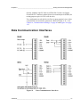
1
USER'S GUIDE
Vaisala Weather Transmitter
WXT510
M210470EN-D
PUBLISHED BY
Vaisala Oyj
Phone (int.):
+358 9 8949 1
P.O. Box 26
Fax:
+358 9 8949 2227
FIN-00421 Helsinki
Finland
Visit our Internet pages at http://www.vaisala.com/
© Vaisala 2006
No part of this manual may be reproduced in any form or by any means,
electronic or mechanical (including photocopying), nor may its contents
be communicated to a third party without prior written permission of the
copyright holder.
The contents are subject to change without prior notice.
Please observe that this manual does not create any legally binding
obligations for Vaisala towards the customer or end user. All legally
binding commitments and agreements are included exclusively in the
applicable supply contract or Conditions of Sale.
________________________________________________________________________________
Table of Contents
CHAPTER 1
GENERAL INFORMATION . . . . . . . . . . . . . . . . . . . . . . . . . . . . . . . . . . . . . . 9
About This Manual . . . . . . . . . . . . . . . . . . . . . . . . . . . . . . . . . 9
Contents of This Manual . . . . . . . . . . . . . . . . . . . . . . . . . . . 9
Feedback . . . . . . . . . . . . . . . . . . . . . . . . . . . . . . . . . . . . . . 10
Safety . . . . . . . . . . . . . . . . . . . . . . . . . . . . . . . . . . . . . . . . . . . 10
General Safety Considerations . . . . . . . . . . . . . . . . . . . . . 10
ESD Protection . . . . . . . . . . . . . . . . . . . . . . . . . . . . . . . . . 11
Recycling . . . . . . . . . . . . . . . . . . . . . . . . . . . . . . . . . . . . . . . . 11
Trademarks . . . . . . . . . . . . . . . . . . . . . . . . . . . . . . . . . . . . . . 12
License Agreement . . . . . . . . . . . . . . . . . . . . . . . . . . . . . . . . 12
Warranty . . . . . . . . . . . . . . . . . . . . . . . . . . . . . . . . . . . . . . . . 13
CHAPTER 2
PRODUCT OVERVIEW . . . . . . . . . . . . . . . . . . . . . . . . . . . . . . . . . . . . . . . 15
Weather Transmitter WXT510 . . . . . . . . . . . . . . . . . . . . . . . 15
Optional Software for Easy Settings . . . . . . . . . . . . . . . . . 16
Heating Function . . . . . . . . . . . . . . . . . . . . . . . . . . . . . . . . 16
WXT510 Transmitter Components . . . . . . . . . . . . . . . . . . . 17
CHAPTER 3
FUNCTIONAL DESCRIPTION . . . . . . . . . . . . . . . . . . . . . . . . . . . . . . . . . . 21
Wind Measurement Principle . . . . . . . . . . . . . . . . . . . . . . . . 21
Precipitation Measurement Principle . . . . . . . . . . . . . . . . . 23
PTU Measurement Principle . . . . . . . . . . . . . . . . . . . . . . . . . 24
Heating (Optional) . . . . . . . . . . . . . . . . . . . . . . . . . . . . . . . . . 24
CHAPTER 4
INSTALLATION . . . . . . . . . . . . . . . . . . . . . . . . . . . . . . . . . . . . . . . . . . . . . 27
Unpacking Instructions . . . . . . . . . . . . . . . . . . . . . . . . . . . . 27
Selecting Location . . . . . . . . . . . . . . . . . . . . . . . . . . . . . . . . 27
Assembling WXT510 . . . . . . . . . . . . . . . . . . . . . . . . . . . . . . . 28
Installation Procedure . . . . . . . . . . . . . . . . . . . . . . . . . . . . . 29
Mounting . . . . . . . . . . . . . . . . . . . . . . . . . . . . . . . . . . . . . . 29
Mounting to Vertical Pole Mast . . . . . . . . . . . . . . . . . . 29
Mounting with Mounting Kit (Optional) . . . . . . . . . . . . . 30
Mounting To Horizontal Cross Arm . . . . . . . . . . . . . . . 31
Aligning WXT510 . . . . . . . . . . . . . . . . . . . . . . . . . . . . . . . 32
Compass Alignment. . . . . . . . . . . . . . . . . . . . . . . . . . . 33
Wind Direction Correction . . . . . . . . . . . . . . . . . . . . . . 34
VAISALA ________________________________________________________________________ 1
________________________________________________________________________________
CHAPTER 5
WIRING AND POWER MANAGEMENT . . . . . . . . . . . . . . . . . . . . . . . . . . .35
Power Supplies . . . . . . . . . . . . . . . . . . . . . . . . . . . . . . . . . . .35
Wiring Using the Screw Terminals . . . . . . . . . . . . . . . . . . .37
Wiring Using the 8-pin M12 Connector (Optional) . . . . . . .39
External Wiring . . . . . . . . . . . . . . . . . . . . . . . . . . . . . . . . . .39
Internal Wiring . . . . . . . . . . . . . . . . . . . . . . . . . . . . . . . . . .40
Data Communication Interfaces . . . . . . . . . . . . . . . . . . . . .41
Power Management . . . . . . . . . . . . . . . . . . . . . . . . . . . . . . . .42
CHAPTER 6
COMMUNICATION SETTINGS . . . . . . . . . . . . . . . . . . . . . . . . . . . . . . . . .45
Communication Protocols . . . . . . . . . . . . . . . . . . . . . . . . . .45
Service Cable Connection . . . . . . . . . . . . . . . . . . . . . . . . . .46
Connection Through M12 Bottom Connector or Screw
Terminal . . . . . . . . . . . . . . . . . . . . . . . . . . . . . . . . . . . . . . .47
Communication Setting Commands . . . . . . . . . . . . . . . . . .48
Checking the Current Communication Settings (aXU) . . . .48
Setting Fields . . . . . . . . . . . . . . . . . . . . . . . . . . . . . . . . . . .49
Changing the Communication Settings . . . . . . . . . . . . . . .51
CHAPTER 7
GETTING THE DATA MESSAGES . . . . . . . . . . . . . . . . . . . . . . . . . . . . . .53
General Commands . . . . . . . . . . . . . . . . . . . . . . . . . . . . . . .53
Reset (aXZ) . . . . . . . . . . . . . . . . . . . . . . . . . . . . . . . . . . . .53
Precipitation Counter Reset (aXZRU) . . . . . . . . . . . . . . . .54
Precipitation Intensity Reset (aXZRI) . . . . . . . . . . . . . . . . .55
Measurement Reset (aXZM) . . . . . . . . . . . . . . . . . . . . . . .56
ASCII Protocol . . . . . . . . . . . . . . . . . . . . . . . . . . . . . . . . . . . .57
Abbreviations and Units . . . . . . . . . . . . . . . . . . . . . . . . . . .57
Device Address (?) . . . . . . . . . . . . . . . . . . . . . . . . . . . . . . .58
Acknowledge Active Command (a) . . . . . . . . . . . . . . . . . .58
Wind Data Message (aR1) . . . . . . . . . . . . . . . . . . . . . . . . .59
Pressure, Temperature and Humidity Data Message
(aR2) . . . . . . . . . . . . . . . . . . . . . . . . . . . . . . . . . . . . . . . . .60
Precipitation Data Message (aR3) . . . . . . . . . . . . . . . . . . .61
Supervisor Data Message (aR5) . . . . . . . . . . . . . . . . . . . .62
Combined Data Message (aR) . . . . . . . . . . . . . . . . . . . . . .62
Composite Data Message Query (aR0) . . . . . . . . . . . . . . .63
Polling with CRC . . . . . . . . . . . . . . . . . . . . . . . . . . . . . . . .64
Automatic Mode . . . . . . . . . . . . . . . . . . . . . . . . . . . . . . . . .65
Automatic Composite Data Message . . . . . . . . . . . . . . . . .66
SDI-12 Protocol . . . . . . . . . . . . . . . . . . . . . . . . . . . . . . . . . . .67
Address Query Command (?) . . . . . . . . . . . . . . . . . . . . . .67
Acknowledge Active Command (a) . . . . . . . . . . . . . . . . . .68
Change Address Command (aAb) . . . . . . . . . . . . . . . . . . .69
Send Identification Command (aI) . . . . . . . . . . . . . . . . . . .69
Start Measurement Command (aM) . . . . . . . . . . . . . . . . . .70
Start Measurement Command with CRC (aMC) . . . . . . . .72
2 _______________________________________________________________________________
________________________________________________________________________________
Start Concurrent Measurement (aC) . . . . . . . . . . . . . . . . . 72
Start Concurrent Measurement with CRC (aCC) . . . . . . . . 73
Send Data Command (aD) . . . . . . . . . . . . . . . . . . . . . . . . 74
Examples of aM, aC and aD Commands . . . . . . . . . . . . . . 75
Continuous Measurement (aR) . . . . . . . . . . . . . . . . . . . . . 77
Continuous Measurement with CRC (aRC) . . . . . . . . . . . . 78
Start Verification Command (aV) . . . . . . . . . . . . . . . . . . . . 78
NMEA 0183 V3.0 Protocol . . . . . . . . . . . . . . . . . . . . . . . . . . . 79
Device Address (?) . . . . . . . . . . . . . . . . . . . . . . . . . . . . . . 79
Acknowledge Active Command (a) . . . . . . . . . . . . . . . . . . 80
MWV Wind Speed and Direction Query . . . . . . . . . . . . . . . 80
XDR Transducer Measurement Query . . . . . . . . . . . . . . . 82
TXT Text Transmission . . . . . . . . . . . . . . . . . . . . . . . . . . . 90
Automatic Mode . . . . . . . . . . . . . . . . . . . . . . . . . . . . . . . . . 91
Automatic Composite Data Message . . . . . . . . . . . . . . . . . 91
CHAPTER 8
SENSOR AND DATA MESSAGE SETTINGS . . . . . . . . . . . . . . . . . . . . . . 93
Wind Sensor . . . . . . . . . . . . . . . . . . . . . . . . . . . . . . . . . . . . . 93
Checking the Settings . . . . . . . . . . . . . . . . . . . . . . . . . . . . 93
Setting Fields . . . . . . . . . . . . . . . . . . . . . . . . . . . . . . . . . . . 95
Changing the Settings . . . . . . . . . . . . . . . . . . . . . . . . . . . . 96
Pressure, Temperature, and Humidity Sensors . . . . . . . . . 99
Checking the Settings . . . . . . . . . . . . . . . . . . . . . . . . . . . . 99
Setting Fields . . . . . . . . . . . . . . . . . . . . . . . . . . . . . . . . . . 100
Changing the Settings . . . . . . . . . . . . . . . . . . . . . . . . . . . 101
Precipitation Sensor . . . . . . . . . . . . . . . . . . . . . . . . . . . . . . 103
Checking the Settings . . . . . . . . . . . . . . . . . . . . . . . . . . . 103
Setting Fields . . . . . . . . . . . . . . . . . . . . . . . . . . . . . . . . . . 104
Changing the Settings . . . . . . . . . . . . . . . . . . . . . . . . . . . 106
Supervisor Message . . . . . . . . . . . . . . . . . . . . . . . . . . . . . . 108
Checking the Settings . . . . . . . . . . . . . . . . . . . . . . . . . . . 108
Setting Fields . . . . . . . . . . . . . . . . . . . . . . . . . . . . . . . . . . 109
Changing the Settings . . . . . . . . . . . . . . . . . . . . . . . . . . . 110
Composite Data Message . . . . . . . . . . . . . . . . . . . . . . . . . . 111
CHAPTER 9
MAINTENANCE . . . . . . . . . . . . . . . . . . . . . . . . . . . . . . . . . . . . . . . . . . . . 113
Cleaning . . . . . . . . . . . . . . . . . . . . . . . . . . . . . . . . . . . . . . . . 113
Replacing the PTU Module . . . . . . . . . . . . . . . . . . . . . . . . . 113
Factory Calibration and Repair Service . . . . . . . . . . . . . . 115
Vaisala Service Centers . . . . . . . . . . . . . . . . . . . . . . . . . . . 115
VAISALA ________________________________________________________________________ 3
________________________________________________________________________________
CHAPTER 10
TROUBLESHOOTING . . . . . . . . . . . . . . . . . . . . . . . . . . . . . . . . . . . . . . .117
Self-Diagnostics . . . . . . . . . . . . . . . . . . . . . . . . . . . . . . . . .119
Error Messaging/Text Messages . . . . . . . . . . . . . . . . . . .119
Rain and Wind Sensor Heating Control . . . . . . . . . . . . . .121
Operating Voltage Control . . . . . . . . . . . . . . . . . . . . . . . .121
Technical Support . . . . . . . . . . . . . . . . . . . . . . . . . . . . . .121
CHAPTER 11
TECHNICAL SPECIFICATIONS . . . . . . . . . . . . . . . . . . . . . . . . . . . . . . . .123
Performance . . . . . . . . . . . . . . . . . . . . . . . . . . . . . . . . . . . .123
Inputs and Outputs . . . . . . . . . . . . . . . . . . . . . . . . . . . . . . .126
Operating Conditions . . . . . . . . . . . . . . . . . . . . . . . . . . . . .126
Materials . . . . . . . . . . . . . . . . . . . . . . . . . . . . . . . . . . . . . . . .127
General . . . . . . . . . . . . . . . . . . . . . . . . . . . . . . . . . . . . . . . . .127
Options and Accessories . . . . . . . . . . . . . . . . . . . . . . . . . .127
Dimensions . . . . . . . . . . . . . . . . . . . . . . . . . . . . . . . . . . . . .128
APPENDIX A
NETWORKING . . . . . . . . . . . . . . . . . . . . . . . . . . . . . . . . . . . . . . . . . . . . .131
Connecting Several WXT510s on the Same Bus . . . . . . .131
SDI-12 Serial Interface . . . . . . . . . . . . . . . . . . . . . . . . . . . .131
Wiring . . . . . . . . . . . . . . . . . . . . . . . . . . . . . . . . . . . . . . . .131
Communication Protocol . . . . . . . . . . . . . . . . . . . . . . . . .132
RS-485 Serial Interface . . . . . . . . . . . . . . . . . . . . . . . . . . . .132
Wiring . . . . . . . . . . . . . . . . . . . . . . . . . . . . . . . . . . . . . . . .132
Communication Protocol . . . . . . . . . . . . . . . . . . . . . . . . .133
ASCII, Polled . . . . . . . . . . . . . . . . . . . . . . . . . . . . . . . . . .133
NMEA 0183 v3.0, Query . . . . . . . . . . . . . . . . . . . . . . . . .133
NMEA 0183 v3.0 Query with ASCII Query Commands . .136
APPENDIX B
SDI-12 PROTOCOL . . . . . . . . . . . . . . . . . . . . . . . . . . . . . . . . . . . . . . . . .139
SDI-12 Electrical Interface . . . . . . . . . . . . . . . . . . . . . . . . .139
SDI-12 Communications Protocol . . . . . . . . . . . . . . . . . .139
SDI-12 Timing . . . . . . . . . . . . . . . . . . . . . . . . . . . . . . . . .140
APPENDIX C
CRC-16 COMPUTATION . . . . . . . . . . . . . . . . . . . . . . . . . . . . . . . . . . . . .143
Encoding the CRC as ASCII Characters . . . . . . . . . . . . . .144
NMEA 0183 v3.0 Checksum Computation . . . . . . . . . . . .144
APPENDIX D
WIND MEASUREMENT AVERAGING METHOD . . . . . . . . . . . . . . . . . . .145
4 _______________________________________________________________________________
________________________________________________________________________________
List of Figures
Figure 1
Figure 2
Figure 3
Figure 4
Figure 5
Figure 6
Figure 7
Figure 8
Figure 9
Figure 10
Figure 11
Figure 12
Figure 13
Figure 14
Figure 15
Figure 16
Figure 17
Figure 18
Figure 19
Figure 20
Figure 21
Figure 22
Figure 23
Figure 24
Figure 25
Vaisala Weather Transmitter WXT510. . . . . . . . . . . . . . . . . . . 15
Main Components of Weather Transmitter WXT510 . . . . . . . . 17
Cut Away View . . . . . . . . . . . . . . . . . . . . . . . . . . . . . . . . . . . . . 18
Bottom of Transmitter. . . . . . . . . . . . . . . . . . . . . . . . . . . . . . . . 18
Mounting Kit (Optional) . . . . . . . . . . . . . . . . . . . . . . . . . . . . . . 19
Service Cable (Optional) . . . . . . . . . . . . . . . . . . . . . . . . . . . . . 19
Assembling WXT510 . . . . . . . . . . . . . . . . . . . . . . . . . . . . . . . . 28
Location of Fixing Screw . . . . . . . . . . . . . . . . . . . . . . . . . . . . . 29
Mounting WXT510 to Pole Mast Using Optional Mounting Kit. 30
Mounting WXT510 to Cross Arm (L-Profile). . . . . . . . . . . . . . . 31
Mounting Screw Location in Cross Arm . . . . . . . . . . . . . . . . . . 32
Sketch of Magnetic Declination . . . . . . . . . . . . . . . . . . . . . . . . 33
Wind Direction Correction . . . . . . . . . . . . . . . . . . . . . . . . . . . . 34
Average Operational Current Consumption (with 4Hz Wind
Sensor Sampling) . . . . . . . . . . . . . . . . . . . . . . . . . . . . . . . . . . 36
Heating Current and Power vs Vh . . . . . . . . . . . . . . . . . . . . . . 37
Screw Terminal Block . . . . . . . . . . . . . . . . . . . . . . . . . . . . . . . 38
8-Pin M12 Connector Pins . . . . . . . . . . . . . . . . . . . . . . . . . . . . 39
Internal Wiring . . . . . . . . . . . . . . . . . . . . . . . . . . . . . . . . . . . . . 40
Data Communication Interfaces. . . . . . . . . . . . . . . . . . . . . . . . 41
Replacing the PTU Module . . . . . . . . . . . . . . . . . . . . . . . . . . 114
Accuracy Over Temperature Range . . . . . . . . . . . . . . . . . . . 124
WXT510 Dimensions in mm [inches] . . . . . . . . . . . . . . . . . . . 128
Mounting Kit Dimensions in mm [inches] . . . . . . . . . . . . . . . . 129
Timing Diagram . . . . . . . . . . . . . . . . . . . . . . . . . . . . . . . . . . . 141
Wind Measurement Averaging Method . . . . . . . . . . . . . . . . . 146
VAISALA ________________________________________________________________________ 5
________________________________________________________________________________
6 _______________________________________________________________________________
________________________________________________________________________________
List of Tables
Table 1
Table 2
Table 3
Table 4
Table 5
Table 6
Table 7
Table 8
Table 9
Table 10
Table 11
Table 12
Table 13
Table 14
Table 15
Table 16
Table 17
Table 18
Table 19
Table 20
Screw Terminal Pin-outs for WXT510 Serial Interfaces and
Power Supplies . . . . . . . . . . . . . . . . . . . . . . . . . . . . . . . . . . . . . . 38
Pin-outs for WXT510 Serial Interfaces and Power Supplies . . . . 39
Available Serial Communication Protocols . . . . . . . . . . . . . . . . . 45
Default Serial Communication Settings for M12/Screw Terminal
Connection . . . . . . . . . . . . . . . . . . . . . . . . . . . . . . . . . . . . . . . . . . 47
Abbreviations and Units . . . . . . . . . . . . . . . . . . . . . . . . . . . . . . . . 57
Transducer IDs of the Measurement Parameters . . . . . . . . . . . . 84
Transducer Table . . . . . . . . . . . . . . . . . . . . . . . . . . . . . . . . . . . . . 90
Data Validation. . . . . . . . . . . . . . . . . . . . . . . . . . . . . . . . . . . . . . . 117
Communication Problems . . . . . . . . . . . . . . . . . . . . . . . . . . . . . . 118
Error Messaging/Text Messages Table . . . . . . . . . . . . . . . . . . . . 120
Barometric Pressure . . . . . . . . . . . . . . . . . . . . . . . . . . . . . . . . . . 123
Air Temperature . . . . . . . . . . . . . . . . . . . . . . . . . . . . . . . . . . . . . . 123
Relative Humidity . . . . . . . . . . . . . . . . . . . . . . . . . . . . . . . . . . . . . 124
Wind . . . . . . . . . . . . . . . . . . . . . . . . . . . . . . . . . . . . . . . . . . . . . . . 124
Precipitation . . . . . . . . . . . . . . . . . . . . . . . . . . . . . . . . . . . . . . . . . 125
Inputs and Outputs. . . . . . . . . . . . . . . . . . . . . . . . . . . . . . . . . . . . 126
Operating Conditions . . . . . . . . . . . . . . . . . . . . . . . . . . . . . . . . . . 126
Materials . . . . . . . . . . . . . . . . . . . . . . . . . . . . . . . . . . . . . . . . . . . 127
General . . . . . . . . . . . . . . . . . . . . . . . . . . . . . . . . . . . . . . . . . . . . 127
Options and Accessories . . . . . . . . . . . . . . . . . . . . . . . . . . . . . . . 127
VAISALA ________________________________________________________________________ 7
________________________________________________________________________________
8 _______________________________________________________________________________
Chapter 1 ________________________________________________________ General Information
CHAPTER 1
GENERAL INFORMATION
This chapter provides general notes for the product.
About This Manual
This manual provides information for installing, operating, and
maintaining Vaisala Weather Transmitter WXT510.
Contents of This Manual
This manual consists of the following chapters:
-
Chapter 1, General Information: This chapter provides general
notes for the product.
-
Chapter 2, Product Overview: This chapter introduces the unique
features and advantages of the Vaisala Weather Transmitter
WXT510.
-
Chapter 3, Functional Description: This chapter describes the
measurement principles and heating function of Weather
Transmitter WXT510.
-
Chapter 4, Installation: This chapter provides you with information
that is intended to help you install Weather Transmitter WXT510.
-
Chapter 5, Wiring and Power Management: This chapter provides
you with instructions on how to connect the power supply and the
serial interfaces.
VAISALA ________________________________________________________________________ 9
User’s Guide ______________________________________________________________________
-
Chapter 6, Communication Settings: This chapter contains the
instructions for making the communication settings.
-
Chapter 7, Getting the Data Messages: This chapter presents the
general and data message commands.
-
Chapter 8, Sensor and Data Message Settings: This chapter
presents the sensor configuration and data message formatting
commands for all communications protocols: ASCII, NMEA 0183
and SDI-12.
-
Chapter 9, Maintenance: This chapter contains instructions for the
basic maintenance of Weather Transmitter WXT510 and contact
information for Vaisala Service Centers.
-
Chapter 10, Troubleshooting: This chapter describes common
problems, their probable causes and remedies, and includes contact
information for technical support.
-
Chapter 11, Technical Specifications: This chapter provides the
technical data of Weather Transmitter WXT510.
Feedback
Vaisala Customer Documentation Team welcomes your comments and
suggestions on the quality and usefulness of this publication. If you find
errors or have other suggestions for improvement, please indicate the
chapter, section, and page number. You can send comments to us by email: [email protected].
Safety
General Safety Considerations
Throughout the manual, important safety considerations are highlighted
as follows:
WARNING
Warning alerts you to a serious hazard. If you do not read and follow
instructions very carefully at this point, there is a risk of injury or even
death.
10 __________________________________________________________________ M210470EN-D
Chapter 1 ________________________________________________________ General Information
CAUTION
Caution warns you of a potential hazard. If you do not read and follow
instructions carefully at this point, the product could be damaged or
important data could be lost.
NOTE
Note highlights important information on using the product.
ESD Protection
Electrostatic Discharge (ESD) can cause immediate or latent damage to
electronic circuits. Vaisala products are adequately protected against
ESD for their intended use. However, it is possible to damage the
product by delivering electrostatic discharges when touching,
removing, or inserting any objects inside the equipment housing.
To make sure you are not delivering high static voltages yourself:
-
Handle ESD sensitive components on a properly grounded and
protected ESD workbench. When this is not possible, ground
yourself with a wrist strap and a resistive connection cord to the
equipment chassis before touching the boards. When neither of the
above is possible, at least touch a conductive part of the equipment
chassis with your other hand before touching the boards.
-
Always hold the boards by the edges and avoid touching the
component contacts.
Recycling
Recycle all applicable material.
Dispose of batteries and the unit according to statutory regulations.
Do not dispose of with regular household refuse.
VAISALA _______________________________________________________________________ 11
User’s Guide ______________________________________________________________________
Trademarks
WINDCAP®, RAINCAP®, HUMICAP®, BAROCAP® and
THERMOCAP® are registered trademarks of Vaisala. Microsoft®,
Windows®, Windows NT®, and Windows XP® are registered
trademarks of Microsoft Corporation in the United States and/or other
countries.
License Agreement
All rights to any software are held by Vaisala or third parties. The
customer is allowed to use the software only to the extent that is
provided by the applicable supply contract or Software License
Agreement.
12 __________________________________________________________________ M210470EN-D
Chapter 1 ________________________________________________________ General Information
Warranty
Vaisala hereby represents and warrants all Products
manufactured by Vaisala and sold hereunder to be free
from defects in workmanship or material during a
period of twelve (12) months from the date of delivery
save for products for which a special warranty is given.
If any Product proves however to be defective in
workmanship or material within the period herein
provided Vaisala undertakes to the exclusion of any
other remedy to repair or at its own option replace the
defective Product or part thereof free of charge and
otherwise on the same conditions as for the original
Product or part without extension to original warranty
time. Defective parts replaced in accordance with this
clause shall be placed at the disposal of Vaisala.
Vaisala also warrants the quality of all repair and
service works performed by its employees to products
sold by it. In case the repair or service works should
appear inadequate or faulty and should this cause
malfunction or nonfunction of the product to which the
service was performed Vaisala shall at its free option
either repair or have repaired or replace the product in
question. The working hours used by employees of
Vaisala for such repair or replacement shall be free of
charge to the client. This service warranty shall be
valid for a period of six (6) months from the date the
service measures were completed.
This warranty is however subject to following
conditions:
a) A substantiated written claim as to any alleged
defects shall have been received by Vaisala within
thirty (30) days after the defect or fault became known
or occurred, and
b) The allegedly defective Product or part shall, should
Vaisala so require, be sent to the works of Vaisala or to
such other place as Vaisala may indicate in writing,
freight and insurance prepaid and properly packed and
labelled, unless Vaisala agrees to inspect and repair the
Product or replace it on site.
This warranty does not however apply when the defect
has been caused through
a) normal wear and tear or accident;
b) misuse or other unsuitable or unauthorized use of
the Product or negligence or error in storing,
maintaining or in handling the Product or any
equipment thereof;
c) wrong installation or assembly or failure to service
the Product or otherwise follow Vaisala's service
instructions including any repairs or installation or
assembly or service made by unauthorized personnel
not approved by Vaisala or replacements with parts not
manufactured or supplied by Vaisala;
d) modifications or changes of the Product as well as
any adding to it without Vaisala's prior authorization;
e) other factors depending on the Customer or a third
party.
Notwithstanding the aforesaid Vaisala's liability under
this clause shall not apply to any defects arising out of
materials, designs or instructions provided by the
Customer.
This warranty is expressly in lieu of and excludes all
other conditions, warranties and liabilities, express or
implied, whether under law, statute or otherwise,
including without limitation any implied warranties of
merchantability or fitness for a particular purpose and
all other obligations and liabilities of Vaisala or its
representatives with respect to any defect or deficiency
applicable to or resulting directly or indirectly from the
Products supplied hereunder, which obligations and
liabilities are hereby expressly cancelled and waived.
Vaisala's liability shall under no circumstances exceed
the invoice price of any Product for which a warranty
claim is made, nor shall Vaisala in any circumstances
be liable for lost profits or other consequential loss
whether direct or indirect or for special damages.
VAISALA _______________________________________________________________________ 13
User’s Guide ______________________________________________________________________
14 __________________________________________________________________ M210470EN-D
Chapter 2 __________________________________________________________ Product Overview
CHAPTER 2
PRODUCT OVERVIEW
This chapter introduces the unique features and advantages of the
Vaisala Weather Transmitter WXT510.
Weather Transmitter WXT510
Figure 1
0504-066
Vaisala Weather Transmitter WXT510
VAISALA _______________________________________________________________________ 15
User’s Guide ______________________________________________________________________
Weather Transmitter WXT510 is a small and lightweight transmitter
that offers six weather parameters in one compact package. WXT510
measures wind speed and direction, precipitation, atmospheric pressure,
temperature and relative humidity.
WXT510 powers up with 5 ... 30 VDC and outputs serial data with a
selectable communication protocol: SDI-12, ASCII automatic & polled
and NMEA 0183 with query option. Four alternative serial interfaces
are selectable: RS-232, RS-485, RS-422 and SDI-12.
The following options are available:
-
Heating function for the precipitation and wind sensors
-
Windows® based Vaisala Configuration Tool software and cable
-
8-pin M12 connector (also with 2 m/10 m cable)
-
Mounting kit
Optional Software for Easy Settings
Windows® based Vaisala Configuration Tool is a user friendly
parameter setting software for WXT510. With this software tool you
can change the device and sensor settings easily in Windows®
environment. See list of options and accessories in Table 20 on page
127.
Heating Function
To improve the accuracy of measurements an optional heating for the
wind and precipitation sensors is available. More about heating in
section Heating (Optional) on page 24.
The heating function option must be chosen when placing the order.
16 __________________________________________________________________ M210470EN-D
Chapter 2 __________________________________________________________ Product Overview
WXT510 Transmitter Components
Figure 2
0505-190
Main Components of Weather Transmitter WXT510
The following numbers refer to Figure 2 on page 17:
1
=
Top of the transmitter
2
=
Radiation shield
3
=
Bottom of the transmitter
4
=
Screw cover
VAISALA _______________________________________________________________________ 17
User’s Guide ______________________________________________________________________
Figure 3
0505-191
Cut Away View
The following numbers refer to Figure 3 on page 18:
1
=
Wind transducers (3 pcs)
2
=
Precipitation sensor
3
=
Pressure sensor inside the PTU module
4
=
Humidity and temperature sensors inside the PTU module
Figure 4
0505-192
Bottom of Transmitter
18 __________________________________________________________________ M210470EN-D
Chapter 2 __________________________________________________________ Product Overview
The following numbers refer to Figure 4 on page 18:
1
=
Alignment direction sign
2
=
Service port
3
=
Water tight cable gland (shown disassembled)
4
=
Opening for cable gland (if unused, cover with hexagonal
plug)
5
=
8-pin M12 connector for power/datacom cable (optional,
cover with hexagonal plug if unused)
0505-193
Figure 5
Mounting Kit (Optional)
Figure 6
Service Cable (Optional)
0505-194
VAISALA _______________________________________________________________________ 19
User’s Guide ______________________________________________________________________
The following numbers refer to Figure 6 on page 19:
1
=
Battery connector
2
=
D9-connector for PC serial port
3
=
Connector for WXT510 service port (press the white flap
while disconnecting cable)
The service cable, while connected between the service port and PC,
forces the service port to RS-232 / 19200, 8, N, 1.
CAUTION
To prevent ingress of water, dust, and insects, cover the unused
openings at the transmitter bottom with hexagonal rubber plugs
included in the delivery.
20 __________________________________________________________________ M210470EN-D
Chapter 3 ______________________________________________________ Functional Description
CHAPTER 3
FUNCTIONAL DESCRIPTION
This chapter describes the measurement principles and heating function
of Weather Transmitter WXT510.
Wind Measurement Principle
WXT510 uses Vaisala WINDCAP® sensor technology in wind
measurement.
The wind sensor has an array of three equally spaced ultrasonic
transducers on a horizontal plane. Wind speed and wind directions are
determined by measuring the time it takes the ultrasound to travel from
each transducer to the other two.
The wind sensor measures the transit time (in both directions) along the
three paths established by the array of transducers. This transit time
depends on the wind speed along the ultrasonic path. For zero wind
speed, both the forward and reverse transit times are the same. With
wind along the sound path, the up-wind direction transit time increases
and the down-wind transit time decreases.
VAISALA _______________________________________________________________________ 21
User’s Guide ______________________________________________________________________
The wind speed is calculated from the measured transit times using the
following formula:
V w = 0.5 u L u 1 e t f – 1 e t r 0505-216
where
Vw
=
Wind speed
L
=
Distance between the two transducers
tf
=
Transit time in forward direction
tr
=
Transit time in reverse direction
Measuring the six transit times allows Vw to be computed for each of
the three ultrasonic paths. The computed wind speeds are independent
of altitude, temperature and humidity, which are cancelled out when the
transit times are measured in both directions, although the individual
transit times depend on these parameters.
Using Vw values of two array paths is enough to compute wind speed
and wind direction. A signal processing technique is used so that wind
speed and wind direction are calculated from the two array paths of best
quality.
The wind speed is represented as a scalar speed in selected units (m/s,
kt, mph, km/h). The wind direction is expressed in degrees (°). The
wind direction reported by WXT510 indicates the direction that the
wind comes from. North is represented as 0°, east as 90°, south as 180°,
and west as 270°.
The wind direction is not calculated when the wind speed drops below
0.05 m/s. In this case, the last calculated direction output remains until
the wind speed increases again to the level of 0.05 m/s.
The average values of wind speed and direction are calculated as a
scalar average of of all samples over the selected averaging time
(1 ... 900 s). The sample count depends on the selected sampling rate:
4 Hz (default), 2 Hz or 1 Hz. The minimum and maximum values of
wind speed and direction represent the corresponding extremes during
the selected averaging time. See also Appendix D, Wind Measurement
Averaging Method, on page 145 for averaging method.
22 __________________________________________________________________ M210470EN-D
Chapter 3 ______________________________________________________ Functional Description
Precipitation Measurement Principle
WXT510 uses Vaisala RAINCAP® Sensor 2-technology in
precipitation measurement.
The precipitation sensor comprises of a steel cover and a piezoelectrical
sensor mounted on the bottom surface of the cover.
The precipitation sensor detects the impact of individual raindrops. The
signals from the impact are proportional to the volume of the drops.
Hence, the signal of each drop can be converted directly to accumulated
rainfall. Advanced noise filtering technique is used to filter out signals
originating from other sources than raindrops.
The measured parameters are accumulated rainfall, rain current and
peak intensity, and the duration of a rain event. Detection of each
individual drop enables computing of rain amount and intensity with
high resolution. Precipitation current intensity internally updated every
10 seconds represents the intensity during the one minute period minute
before requesting/automatic precipitation message sending (for fast
reacting to a rain event, during the first minute of the rain event the
intensity is calculated over the period rain has lasted in 10-second steps
instead of fixed one minute). Precipitation peak intensity represents the
maximum of the calculated current intensity values since last
precipitation intensity reset.
The sensor is also capable of distinguishing hails from raindrops. The
measured hail parameters are cumulative amount of hails, current and
peak hail intensity and the duration of a hail shower.
The precipitation sensor operates in the following four modes:
-
Precipitation Start/End mode:
Transmitter sends automatically a precipitation message 10
seconds after the recognition of the first drop. The messages are
sent continuously as the precipitation proceeds and stopped when
the precipitation ends.
-
Tipping bucket mode:
This mode emulates tipping bucket type precipitation sensors.
Transmitter sends automatically a precipitation message when the
counter detects one unit increment (0.1 mm/0.01 in).
VAISALA _______________________________________________________________________ 23
User’s Guide ______________________________________________________________________
-
Time mode:
Transmitter sends automatically a precipitation message in the
update intervals defined by the user.
-
Polled mode:
Transmitter sends a precipitation message whenever requested by
the user.
More information about the precipitation sensor operation modes can be
found in section Precipitation Sensor on page 103.
PTU Measurement Principle
The PTU module contains separate sensors for pressure, temperature,
and humidity measurement.
The measurement principle of the pressure, temperature, and humidity
sensors is based on an advanced RC oscillator and two reference
capacitors against which the capacitance of the sensors is continuously
measured. The microprocessor of the transmitter performs
compensation for the temperature dependency of the pressure and
humidity sensors.
The PTU module includes
-
capacitive silicon BAROCAP® sensor for pressure measurement,
-
capacitive ceramic THERMOCAP® sensor for air temperature
measurement, and
-
capacitive thin film polymer HUMICAP®180 sensor for humidity
measurement.
Heating (Optional)
Heating elements located below the precipitation sensor and inside the
wind transducers keeps the precipitation and wind sensors clean from
snow and ice. A heating temperature sensor (Th) underneath the
precipitation sensor controls the heating.
24 __________________________________________________________________ M210470EN-D
Chapter 3 ______________________________________________________ Functional Description
Three fixed temperature limits, namely +4 °C, 0 °C, and -4 °C (+39 °F,
+32 °F, +25 °F)control the heating power as follows:
Th > +4 °C: heating is off,
0 °C < Th < +4 °C: 50 % heating power,
-4 °C < Th < 0 °C: 100 % heating power,
Th < -4 °C: 50 % heating power.
When the heating function is disabled the heating is off in all conditions,
see Supervisor Message on page 108.
VAISALA _______________________________________________________________________ 25
User’s Guide ______________________________________________________________________
26 __________________________________________________________________ M210470EN-D
Chapter 4 _______________________________________________________________ Installation
CHAPTER 4
INSTALLATION
This chapter provides you with information that is intended to help you
install Weather Transmitter WXT510.
Unpacking Instructions
Weather Transmitter WXT510 comes in a custom shipping container.
Be careful when removing the device from the container.
CAUTION
Beware of damaging any of the wind transducers located at the top of
the three antennas. Dropping the device can break or damage the
transducers. If the antenna bends or twists, re-aligning can be difficult
or impossible.
Selecting Location
Finding a suitable site for Weather Transmitter WXT510 is important
for getting representative ambient measurements. The site should
represent the general area of interest.
Weather Transmitter WXT510 should be installed in a location that is
free from turbulence caused by nearby objects, such as trees or
buildings.
WARNING
To protect personnel (and the device), a lightning rod should be
installed with the tip at least one meter above WXT510. The rod must
be properly grounded, compliant with all applicable local safety
regulations.
VAISALA _______________________________________________________________________ 27
User’s Guide ______________________________________________________________________
Assembling WXT510
1.
Loosen the three fixing screws at the sensor bottom assembly.
2.
Turn out the top of the transmitter.
3.
Remove the vacuum bag protecting the PTU module. Connect the
new PTU module. Make sure the module goes all the way in and is
locked into its position with the small white latch (see section A in
Figure 7 on page 28).
4.
Avoid contacting the white filter cap with your hands while
inserting the PTU module.
5.
Replace the top and tighten the three fixing screws that fasten the
top and the bottom. When turning the top back in, make sure that
the flat cable does not get stuck or squeezed between the top and
the funnel for the flat cable.
Figure 7
0602-013
Assembling WXT510
28 __________________________________________________________________ M210470EN-D
Chapter 4 _______________________________________________________________ Installation
Installation Procedure
At the measurement site, WXT510 needs to be mounted, aligned, and
connected to the data logger and the power source.
Mounting
Weather Transmitter WXT510 can be mounted either onto a vertical
pole mast or onto a horizontal cross arm. When mounting WXT510
onto a pole mast, an optional mounting kit can be used to ease
mounting. When using the optional mounting kit, alignment is needed
only when mounted for the first time.
Each of the mounting options is further described in the following
sections.
NOTE
Weather Transmitter WXT510 must be installed to an upright, vertical
position.
Mounting to Vertical Pole Mast
1.
Remove the screw cover and insert WXT510 to the pole mast.
2.
Align the transmitter in such a way that the arrow points to north.
3.
Tighten the fixing screw (provided) and replace the screw cover.
Figure 8
0505-197
Location of Fixing Screw
VAISALA _______________________________________________________________________ 29
User’s Guide ______________________________________________________________________
Mounting with Mounting Kit (Optional)
1.
Insert the mounting kit adapter to the transmitter bottom in the
position shown in the picture.
2.
Turn the kit inside the bottom firmly until you feel that the adapter
snaps into the locked position.
3.
Mount the adapter to the pole mast, do not tighten the fixing screw
(provided).
4.
Align the transmitter in such a way that the arrow points to north.
5.
Tighten the fixing screw to fix the adapter firmly to the pole mast.
Figure 9
0505-198
Mounting WXT510 to Pole Mast Using Optional
Mounting Kit
The following numbers refer to Figure 9 on page 30:
NOTE
1
=
Mounting kit
2
=
Fixing screw
When removing WXT510 from the pole just turn the transmitter so
that it snaps out from the mounting kit. When replacing the device the
alignment is not needed.
30 __________________________________________________________________ M210470EN-D
Chapter 4 _______________________________________________________________ Installation
Mounting To Horizontal Cross Arm
1.
Remove the screw cover.
2.
Align the horizontal cross arm in south-north-direction, see
Aligning WXT510 on page 32.In case the cross arm cannot be
aligned, make the wind direction correction as instructed in section
Wind Direction Correction on page 34.
3.
Mount the transmitter into the cross arm by using the fixing screw
(M6 DIN933) and a nut, see Figure 9 on page 30 and Figure 10 on
page 31.
Figure 10
0505-199
Mounting WXT510 to Cross Arm (L-Profile)
The following numbers refer to Figure 10 on page 31:
1
=
Nut
2
=
Fixing screw (M6 DIN933)
VAISALA _______________________________________________________________________ 31
User’s Guide ______________________________________________________________________
Figure 11
0505-200
Mounting Screw Location in Cross Arm
Aligning WXT510
To help the alignment, there is an arrow and the text "North" on the
bottom of the transmitter. WXT510 should be aligned in such a way that
this arrow points to the north.
Wind direction can be referred either to true north, which uses the
earth’s geographic meridians, or to the magnetic north, which is read
with a magnetic compass. The magnetic declination is the difference in
degrees between the true north and magnetic north. The source for the
magnetic declination should be current as the declination changes over
time.
32 __________________________________________________________________ M210470EN-D
Chapter 4 _______________________________________________________________ Installation
Figure 12
0003-011
Sketch of Magnetic Declination
Compass Alignment
To align Weather Transmitter WXT510, proceed as follows:
1.
If WXT510 is already mounted, loosen the fixing screw on the
bottom of the transmitter so that you can rotate the device.
2.
Use a compass to determine that the transducer heads of WXT510
are exactly in line with the compass and that the arrow on the
bottom of WXT510 points to the north.
3.
Tighten the fixing screw on the bottom of the transmitter when the
bottom arrow is exactly aligned to north.
VAISALA _______________________________________________________________________ 33
User’s Guide ______________________________________________________________________
Wind Direction Correction
Make a wind direction correction in case WXT510 cannot be aligned in
such a way that the arrow on the bottom points to the north. In this case,
the deviation angle from the true north should be given to WXT510.
1.
Mount the transmitter to a desired position, see section Mounting
on page 29.
2.
Define the deviation angle from the north-zero-alignment. Use the
± sign indication to express the direction from the north line (see
example pictures).
3.
Feed the deviation angle to the device by using the wind message
formatting command aWU,D (direction correction), see section
Checking the Settings on page 93.
4.
From now on, WXT510 transmits the wind direction data by using
the changed zero-alignment.
Figure 13
0505-201
Wind Direction Correction
34 __________________________________________________________________ M210470EN-D
Chapter 5 _______________________________________________ Wiring and Power Management
CHAPTER 5
WIRING AND POWER MANAGEMENT
This chapter provides you with instructions on how to connect the
power supply and the serial interfaces.
WXT510 can be accessed through four different serial interfaces: RS232, RS-485, RS-422 and SDI-12. Each of them can be wired either
through the internal screw terminal or the 8-pin M12 connector
(optional). Only one serial interface can be used at a time.
CAUTION
Cover the unused cable openings (in the transmitter bottom) with the
hexagonal rubber plugs included in the accessories.
Power Supplies
Operating voltage Vin+: 5 ... 30 VDC
Notice that for the average current consumption, see the graphs in
Figure 14 on page 36. The minimum consumption graph is for SDI-12
standby mode.
The input power supply shall be capable to deliver 60 mA (at 12 V) or
100 mA (at 6 V) instant current spikes with duration of 30 ms. These
are drawn by the wind sensor (whenever enabled) at 4 Hz rate, which is
the default value for wind sampling. Wind sampling at 2 Hz or 1 Hz rate
is also available (see Chapter 8, Sensor and Data Message Settings, on
page 93). The average current consumption will decrease almost in
proportion to the sampling rate, since wind measurement is the most
consuming operation in the system.
VAISALA _______________________________________________________________________ 35
User’s Guide ______________________________________________________________________
In most occasions the average consumption is less than 10 mA.
Typically, the higher the voltage the lower the current, but with voltages
above 18 V the current will gradually increase, adding to the usual
consumption an extra 4 mA at 24 V (see Figure 14 on page 36).
Figure 14
0505-202
Average Operational Current Consumption (with
4Hz Wind Sensor Sampling)
Heating voltage Vh+ (one of the following three alternatives):
-
5 ... 30 VDC;
-
AC, max Vpeak-to-peak 84 V (= 30 VRMS); or
-
Full-wave rectified AC, max Vpeak 42 V (= 30 VRMS).
The recommended DC voltage ranges are as follows:
-
12 VDC ± 20 % (max 1.1 A);
-
24 VDC ± 20 % (max 0.6 A).
At approximately 16 V heating voltage level WXT510 automatically
changes the heating element combination in order to consume equal
power with 12 VDC and 24 VDC supplies. Input resistance (Rin) is
radically increased with voltages above 16 V (see the following graph).
The recommended ranges for AC or full-wave rectified AC are:
-
68 Vp-p ± 20 % (max 0.6 A), for AC;
-
34 Vp ± 20 % (max 0.6 A), for f/w rectified AC.
36 __________________________________________________________________ M210470EN-D
Chapter 5 _______________________________________________ Wiring and Power Management
Figure 15
0505-203
Heating Current and Power vs Vh
CAUTION
To avoid exceeding the maximum ratings in any condition, the
voltages must be checked with no load at the power supply output.
WARNING
Make sure that you connect only de-energized wires.
Wiring Using the Screw Terminals
1.
Loosen the three long screws at the bottom of WXT510.
2.
Pull out the bottom part of the transmitter.
3.
Insert the power supply wires and signal wires through the cable
gland(s) in the bottom of the transmitter.
4.
Connect the wires according to Table 1 on page 38.
5.
Replace the bottom part and tighten the three screws.
VAISALA _______________________________________________________________________ 37
User’s Guide ______________________________________________________________________
0505-204
Figure 16
Screw Terminal Block
Table 1
Screw Terminal Pin-outs for WXT510 Serial
Interfaces and Power Supplies
Screw Terminal
Pin
RS-232
SDI-12
RS-485
RS-422
1 RX2 RX+
3 TX4 TX+
5 RXD
6 SGND
17 HTG18 HTG+
19 VIN20 VIN+
Data out (TxD)
Data in (RxD)
GND for data
GND for Vh+
Vh+ (heating)
GND for Vin+
Vin+ (operating)
Data in/out (Tx)
Data in/out (Rx)
GND for data
GND for Vh+
Vh+ (heating)
GND for Vin+
Vin+ (operating)
DataData+
DataData+
GND for Vh+
Vh+ (heating)
GND for Vin+
Vin+ (operating)
Data in (RX-)
Data in (RX+)
Data out (TX-)
Data out (TX+)
GND for Vh+
Vh+ (heating)
GND for Vin+
Vin+ (operating)
NOTE
In the true SDI-12 mode the two Data in/out lines must be combined
either in the screw terminal or outside WXT510.
NOTE
Short-circuit jumpers are required between pins 1-3 and 2-4 for the
RS-485 communication mode. For the RS-422 mode, the jumpers
should be removed. In the other modes the jumpers may stay or they
can be removed.
38 __________________________________________________________________ M210470EN-D
Chapter 5 _______________________________________________ Wiring and Power Management
Wiring Using the 8-pin M12 Connector
(Optional)
External Wiring
If WXT510 is provided with the optional 8-pin M12 connector, the
connector is located on the bottom of the transmitter, see Figure 4 on
page 18. The pins of the 8-pin M12 connector as seen from outside the
transmitter are illustrated in the following figure.
Figure 17
0308-032
8-Pin M12 Connector Pins
The pin connections for the 8-pin M12 connector and the wire colors of
the respective M12 cable (optional, 2/10 m) are listed in the table below.
Table 2
Pin-outs for WXT510 Serial Interfaces and Power
Supplies
/------------------ Default wiring ------------------\
RS-422 wiring
Wire Color
M12 Pin#
RS-232
SDI-12
RS-485
RS-422
Blue
Gray
White
Green
Pink
Yellow
7
5
1
3
6
4
8
Data out (TxD)
Data in (RxD)
GND for data
GND for Vh+
Vh+ (heating)
GND for Vin+
Data in/out (Tx)
Data in/out (Rx)
GND for data
GND for Vh+
Vh+ (heating)
GND for Vin+
DataData+
GND for Vh+
Vh+ (heating)
GND for Vin+
Data in (RX-)
Data in (RX+)
Data out (TX-)
Data out (TX+)
GND for Vh+
Vh+ (heating)
GND for Vin+
2
Vin+
(operating)
Vin+
(operating)
Vin+
(operating)
Vin+
(operating)
Red/Clear1
Brown
1. Red in the internal wiring, clear in the cable (a non-insulated drain wire)
The signal names Data in (RxD) and Data out (TxD) in the table
describe the direction of data flow as seen from WXT510.
VAISALA _______________________________________________________________________ 39
User’s Guide ______________________________________________________________________
The terms "Default wiring" and "RS-422 wiring" refer to the two
internal wiring options, see the diagrams on the next page.
Internal Wiring
The 8-pin M12 connector is optional and hence may not be readily
installed. For retrofitting, make the wiring between the connector and
the screw terminal block according to one of the following pictures.
Figure 18
0505-205
Internal Wiring
The telecommunication modes RS-232, SDI-12, and RS-485 can all be
accomplished with Default wiring, whereas the 4-wire RS-422 requires
a different internal wiring (see also Table 2 on page 39).
The RS-232 interface can be accessed with a standard PC ComPort,
right through the M12 connector. Same applies to the SDI-12 interface,
since the Rx and Tx lines are separate at the M12 connector.
NOTE
The true SDI-12 line requires that the Rx and Tx wires are joined
together (outside WXT510). See the interface diagrams in the next
section.
Bidirectional use of the RS-485 and RS-422 interface requires a proper
adapter module between the PC and WXT510. For testing purposes, the
inverted output of either interface (screw terminal pin #3 TX-) is
40 __________________________________________________________________ M210470EN-D
Chapter 5 _______________________________________________ Wiring and Power Management
directly readable with PC's Received Data line. In this case Signal
Ground for PC ComPort is taken from screw terminal pin #6 SGND (for
testing purposes pin #19 VIN- will also do).
For configuration work, the Service Port is most practical, since it has
constant and convenient line parameters: RS232/19200, 8, N, 1. See
Chapter 6, Communication Settings, on page 45 and Figure 4 on page
18).
Data Communication Interfaces
Figure 19
0505-206
Data Communication Interfaces
VAISALA _______________________________________________________________________ 41
User’s Guide ______________________________________________________________________
With RS-485 and RS-422 interfaces, termination resistors should be
used at both ends of the line, if data rate is 9600 Bd or higher and
distance is 600 m (2000 ft) or longer. Resistor range 100 ... 180 Ω is
suitable for twisted pair lines. Resistors are connected across RX- to
RX+ and across TX- to TX+ (with RS-485 only one resistor needed).
The termination resistors will remarkably increase power consumption
during data transmission. If low power consumption is a must, a 0.1 μF
capacitor should be connected in series with each termination resistor.
Note that the RS-485 interface can be used as well with four wires (as
the RS-422). The basic difference between the RS-485 and RS-422 is
actually their protocol. Namely, in the RS-422 mode the transmitter is
held constantly enabled, while in the RS-485 mode it is enabled only
during transmission (for allowing the host’s transmission in the twowire case).
The RS-232 output swings only between 0 ... +4.5 V. This is enough for
modern PC inputs.The recommended maximum for RS-232 line length
is 100 m (300 ft) with 1200 Bd data rate. Higher rates require shorter
distance, for instance 30 m (100 ft) with 9600 Bd.
NOTE
When WXT510 is used on an RS-485 bus with other polled devices,
the error messaging feature shall always be disabled. This is done by
the following command: 0SU,S=N<crlf>.
Power Management
The power consumption of the WXT510 varies a lot, depending on the
selected operating mode or protocol, the data interface type, the sensor
configuration, and the measurement and reporting intervals. Lowest
consumption is achieved with the Native SDI-12 mode, typically less
than 1 mW in standby (0.07 mA @ 12 V), while with ASCII RS-232
or Continuous SDI-12 modes it is 2 ... 3 times higher. Any sensor
measurement, while being activated, adds its own extra consumption to
the standby power.
Some hints for economic power management are given below. The
current consumption values are all defined for 12 V supply. For 6 V
supply, multiply the values by 1.9. For 18 V or higher supply voltages,
multiply the values by 0.7 and add 1.5 mA for each 1 V increase above
18 V (see Figure 14 on page 36).
42 __________________________________________________________________ M210470EN-D
Chapter 5 _______________________________________________ Wiring and Power Management
-
Wind measurement is absolutely the most consuming operation
in the system. So, it all depends on how the wind is to be reported.
If long time averages are needed, the wind must be constantly
measured - then it makes no big difference, which requesting
period or mode is used. Fully continuous wind measurement with
4 Hz sampling rate adds 2 ... 5 mA to the standby current
(depending on the wind and some other climatic conditions). But
for instance 10 second average requested every 2 minutes
consumes 12 times less. And 1 Hz sampling rate makes it further
decrease to one fourth.
-
PTU measurement adds approximately 0.75 mA to the standby
consumption. Each single measurement of PTU takes 5 seconds
(including the warm-up period). This can be used for estimating the
average consumption of PTU.
-
Continuous precipitation adds some 0.07 mA to the standby
consumption. A single, isolated raindrop causes an additional
0.04 mA to the standby consumption, this condition lasting about
10 seconds (continued, if more raindrops are detected within the
10-second period).
-
ASCII RS-232 Standby consumption with baud rates 4800 and
higher is typically 0.19 mA. With a low baud rate selection (1200
or 2400 Bd) this is reduced by 28% to less than 0.14 mA. The
jumper wires across TX+/RX+ and TX-/RX- add an extra 0.01 0.02 mA (they are necessary only in 2-wire RS-485 mode).
-
ASCII RS-232 Polling mode and Automatic mode have equal
consumption. Thus Automatic mode is a little more economic,
since interpreting the poll takes more prosessing time than starting
the Automatic message. However, care should be taken when
selecting Precipitation Autosend mode, where the submodes M=R
and M=C may cause extra consumption in rainy conditions, as
triggered to send messages by the rain incidents.
-
ASCII RS-232 Data transmission adds 1 ... 2 mA to the standby
consumption during the message sending time. Also it should be
noted that the host device's input (data logger or PC) may
constantly draw some current from the TX line.
-
RS-485 and RS-422 Data interfaces consume about the same as
RS-232. But with long data cables the consumption during data
transmission may be a lot higher, especially when termination
resistors are used. On the other hand, the RS-485 driver is in high
impedance state when not transmitting - thus in idle state no current
can be drawn by the host input.
-
NMEA modes consume about the same as ASCII modes.
VAISALA _______________________________________________________________________ 43
User’s Guide ______________________________________________________________________
NOTE
-
SDI-12 Native mode (M=S, C=1) has the lowest standby
consumption, about 0.07 mA. Note that it can also be used with
RS-232 terminals (PC or equivalent), see the SDI-12 connection
diagram in Figure 19 on page 41. In this case the commands must
be in SDI-12 format, but no special line break signals are required.
The SDI-12 mode is for polling only.
-
SDI-12 Continuous mode (M=R) consumes about the same as the
ASCII RS-232 mode.
If Heating function is enabled, SDI-12 Native mode consumes the
same as ASCII RS-232 mode.
When heating is on (or temperature is such it should be on), some
0.15 mA extra current is drawn from the operational power supply.
NOTE
While in Service mode and/or while supplied through the Service port
the WXT510 consumes 0.5 ... 1 mA more than in normal mode,
supplied through the Main port (M12 connector or screw terminals).
When supplied through the Service port the minimum voltage level for
reliable operation is 6V. This can also be seen in the supply voltage
reading of the Supervisor message - the Vs value is 1V lower than the
actual input voltage.
44 __________________________________________________________________ M210470EN-D
Chapter 6 ____________________________________________________ Communication Settings
CHAPTER 6
COMMUNICATION SETTINGS
This chapter contains the instructions for making the communication
settings.
Communication Protocols
As soon as WXT510 has been properly connected and powered the data
transmission can be started. The communication protocols available in
each of the serial interfaces are shown in the following table.
Table 3
Available Serial Communication Protocols
Serial Interface
Communication Protocols Available
RS-232
ASCII automatic and polled
NMEA 0183 v3.0 automatic and query
SDI-12 v1.3 and SDI-12 v1.3 continuous measurement
ASCII automatic and polled
NMEA 0183 v3.0 automatic and query
SDI-12 v1.3 and SDI-12 v1.3 continuous measurement
ASCII automatic and polled
NMEA 0183 v3.0 automatic and query
SDI-12 v1.3 and SDI-12 v1.3 continuous measurement
SDI-12 v1.3 and SDI-12 v1.3 continuous measurement
RS-485
RS-422
SDI-12
You have chosen the communication protocol (ASCII, NMEA 0183 or
SDI-12) when placing the order. In case you want to check and/or
change the protocol or other communication settings, see the following
sections.
VAISALA _______________________________________________________________________ 45
User’s Guide ______________________________________________________________________
NOTE
The RS-485 and RS-422 interfaces cannot be directly accessed with a
standard PC terminal. They require a suitable converter.
NOTE
RS-232 and SDI-12 can be accessed with a standard PC terminal,
presuming that, for SDI-12, the Data in/out lines have not been
combined inside WXT510.
Service Cable Connection
The service cable connection with fixed serial port settings is
recommended for checking/changing the device settings. When making
the changes, use the Vaisala Configuration Tool or a standard PC
terminal program.
The service cable is included in the Vaisala Configuration Tool kit, see
Table 20 on page 127. For a picture of the service cable, see Figure 6 on
page 19.
When you connect the service cable between the service connector and
PC serial port, the serial port settings are forced automatically to RS232 / 19200, 8, N, 1. At the same time, the normal serial port at M12 and
at screw terminals is disabled. The battery (9 V) attached to a cable
provides the power to WXT510. Alternatively the normal power
connection through M12 or screw terminals can be used (simultaneous
use with 9 V battery is allowed).
1.
Make a connection between the serial port of your PC and the
service port connector on the bottom plate of the transmitter (see
Figure 4 on page 18) by using the service cable.
2.
Power-up WXT510 with a 9 V battery attached to the service cable
or by using the screw terminals/M12 connector.
3.
Open the Vaisala Configuration Tool/terminal program. Select the
following default communication settings: 19200, 8, N, 1.
4.
Make the desired changes. When working with a terminal program,
see section Communication Setting Commands on page 48.
46 __________________________________________________________________ M210470EN-D
Chapter 6 ____________________________________________________ Communication Settings
NOTE
Changes in the serial interface/communication protocol/baud settings
take place when disconnecting the service cable or when resetting the
sensor.
If these settings are not changed during the service connection session,
original main port settings (at M12 and screw terminals) are returned,
as soon as the service cable is disconnected from either end.
Connection Through M12 Bottom
Connector or Screw Terminal
Checking/changing the device settings can also be made through the
M12 bottom connector or screw terminal. Then you have to have know
the communication settings of the device, have a suitable cable between
the device and the host and, if needed, use a converter (for example, RS485/422 to RS-232 if the host is a PC). The factory defaults settings are
as follows:
Table 4
Default Serial Communication Settings for M12/
Screw Terminal Connection
Serial Interface
Serial Settings
SDI-12
RS-232, ASCII
RS-485, ASCII
RS-422 ASCII
RS-422 NMEA
1200 baud, 7, E, 1
19200 baud, 8, N, 1
19200 baud, 8, N, 1
19200 baud, 8, N, 1
4800 baud, 8, N, 1
VAISALA _______________________________________________________________________ 47
User’s Guide ______________________________________________________________________
Communication Setting Commands
NOTE
Hereafter the commands to be typed are presented in normal text while
the responses of the transmitter are presented in italic.
Checking the Current
Communication Settings (aXU)
With this command you can request the current communication settings
of WXT510.
Command format in ASCII and NMEA 0183: aXU<cr><lf>
Command format in SDI-12: aXXU!
where
a
=
Device address, which may consist of the following
characters: 0 (default) ... 9, A ... Z, a ... z.
XU
=
Device settings command in ASCII and NMEA 0183
XXU
=
Device settings command in SDI-12
<cr><lf>
=
Command terminator in ASCII and NMEA 0183
!
=
Command terminator in SDI-12
Example response in ASCII and NMEA 0183:
aXU,A=a,M=[M],T=[T],C=[C],I=[I],B=[B],D=[D],P=[P],S=[S],
L=[L],N=[N],V=[V]<cr><lf>
Example response in SDI-12:
aXXU,A=a,M=[M],T=[T],C=[C],I=[I],B=[B],D=[D],P=[P],S=[S],
L=[L],N=[N],V=[V]<cr><lf>
48 __________________________________________________________________ M210470EN-D
Chapter 6 ____________________________________________________ Communication Settings
Setting Fields
a
=
Device address
XU
=
Device settings command in ASCII and NMEA 0183
XXU
=
Device settings command in SDI-12
[A]
=
Address: 0 (default) ... 9, A ... Z, a ... z
[M]
=
Communication protocol:
A = ASCII, automatic
a = ASCII, automatic with CRC
P = ASCII, polled
p = ASCII, polled, with CRC
N = NMEA 0183 v3.0, automatic
Q = NMEA 0183 v3.0, query (= polled)
S = SDI-12 v1.3
R = SDI-12 v1.3 continuous measurement
[T]
=
Test parameter (for testing use only)
[C]
=
Serial interface: 1 = SDI-12, 2 = RS-232, 3= RS-485,
4 = RS-422
[I]
=
Automatic repeat interval for Composite data
message:1 ... 3600 s, 0 = no automatic repeat
[B]
=
Baud rate: 1200, 2400, 4800, 9600, 19200, 38400,
57600, 115200
[D]
=
Data bits: 7/8
[P]
=
Parity: O = Odd, E = Even, N = None
[S]
=
Stop bits: 1/2
VAISALA _______________________________________________________________________ 49
User’s Guide ______________________________________________________________________
NOTE
[L]
=
RS-485 line delay: 0 ... 10000 ms
Defines the delay between the last character of the
query and the first character of the response message
from WXT510. During the delay, the WXT510's
transmitter is disabled. Effective in ASCII, polled
and NMEA 0183 query protocols. Effective when
RS-485 is selected (C = 3).
[N]
=
Name of the device: WXT510 (read only)
[V]
=
Software version: for example, 1.00 (read only)
<cr><lf>
=
Response terminator
There are two different SDI-12 modes available for providing all the
functionality of the SDI-12 v1.3 standard.
The lowest power consumption is achieved with the Native SDI-12
mode (aXU,M=S), as it makes measurements and outputs data only on
request.
In the continuous SDI-12 mode (aXU,M=R) internal measurements
are made at a user-configurable update interval, see Chapter 8, Sensor
and Data Message Settings, on page 93. The data is outputted on
request.
Example (ASCII and NMEA 0183, device address 0):
0XU<cr><lf>
0XU,A=0,M=P,T=0,C=2,I=0,B=19200,D=8,P=N,S=1,L=25,
N=WXT510,V=1.00<cr><lf>
Example (SDI-12, device address 0):
0XXU!0XXU,A=0,M=S,T=0,C=1,I=0,B=1200,D=7,P=E,S=1,L=25,
N=WXT510,V=1.00<cr><lf>
50 __________________________________________________________________ M210470EN-D
Chapter 6 ____________________________________________________ Communication Settings
Changing the Communication
Settings
Make the desired setting with the following command. Select the
correct value/letter for the setting fields, see Setting Fields on page 49.
See also the examples.
Command format in ASCII and NMEA 0183:
aXU,A=x,M=x,C=x,I=x,B=x,D=x,P=x,S=x,L=x<cr><lf>
Command format in SDI-12:
aXXU,A=x,M=x,C=x,I=x,B=x,D=x,P=x,S=x,L=x!
where
NOTE
A, M, C, I, =
B, D, P, S,L
The communication setting fields, see Setting Fields
on page 49.
x
=
Input value for the setting
<cr><lf>
=
Command terminator in ASCII and NMEA 0183
!
=
Command terminator in SDI-12
When changing the serial interface and communication protocol, note
the following:
Each serial interface requires its specific wiring and/or jumper settings
described in Chapter 5, Wiring and Power Management, on page 35.
Change first the serial interface field C and then the communication
protocol field M.
Changing the serial interface to SDI-12 (C=1) will automatically
change the baud settings to 1200, 7, E, 1 and the communication
protocol to SDI-12 (M=S).
NOTE
Reset the transmitter to validate the changes of communication
parameters by disconnecting the service cable or using the Reset
(aXZ) command, see Reset (aXZ) on page 53.
VAISALA _______________________________________________________________________ 51
User’s Guide ______________________________________________________________________
Example (ASCII and NMEA 0183, device address 0):
Changing the device address from 0 to 1:
0XU,A=1<cr><lf>
1XU,A=1<cr><lf>
Checking the changed settings:
1XU<cr><lf>
1XU,A=1,M=P,T=1,C=2,I=0,B=19200,D=8,P=N,S=1,L=25,
N=WXT510,V=1.00<cr><lf>
Example (ASCII, device address 0):
Changing RS-232 serial interface with ASCII, polled communication
protocol and baud settings 19200, 8, N, 1 to RS-485 serial interface with
ASCII, automatic protocol and baud settings 9600, 8, N, 1.
Checking the actual settings:
0XU<cr><lf>
0XU,A=0,M=P,C=2,I=0,B=19200,D=8,P=N,S=1,L=25,N=WXT510,
V=1.00<cr><lf>
NOTE
You can change several parameters in the same command as long as
the command length does not exceed 32 characters (including
command terminator characters ! or <cr><lf>).You do not have to type
those setting fields that are not to be changed.
Changing several settings with one command:
0XU,M=A,C=3,B=9600<cr><lf>
0XU,M=A,C=3,B=9600<cr><lf>
Checking the changed settings:
0XU<cr><lf>
0XU,A=0,M=A,T=1,C=3,I=0,B=9600,D=8,P=N,S=1,L=25,
N=WXT510,V=1.00<cr><lf>
52 __________________________________________________________________ M210470EN-D
Chapter 7 __________________________________________________ Getting the Data Messages
CHAPTER 7
GETTING THE DATA MESSAGES
This chapter presents the general and data message commands.
Each communication protocol has its own section for data message
commands.
For changing the message parameters, units and other settings, see
Chapter 8, Sensor and Data Message Settings, on page 93.
NOTE
Type commands in CAPITAL letters.
General Commands
In case the error messaging is disabled (see Supervisor Message on page
108), WXT510 does not return any response message with the general
commands given in ASCII and NMEA-formats.
Reset (aXZ)
This command is used to perform software reset on the device.
Command format in ASCII and NMEA 0183: aXZ<cr><lf>
Command format in SDI-12: aXZ!
VAISALA _______________________________________________________________________ 53
User’s Guide ______________________________________________________________________
where
a
=
Device address
XZ
=
Reset command
<cr><lf>
=
Command terminator in ASCII and NMEA 0183
!
=
Command terminator in SDI-12
The response depends on the communication protocol, see the
examples.
Example (ASCII):
0XZ<cr><lf>
0TX,Start-up<cr><lf>
Example (SDI-12):
0XZ!0<cr><lf> (=device address)
Example (NMEA 0183):
0XZ<cr><lf>
$WITXT,01,01,07,Start-up*29
Precipitation Counter Reset
(aXZRU)
This command is used to reset the rain and hail accumulation and
duration parameters Rc, Rd, Hc, and Hd.
Command format in ASCII and NMEA 0183: aXZRU<cr><lf>
Command format in SDI-12: aXZRU!
where
a
=
Device address
XZRU
=
Precipitation counter reset command
<cr><lf>
=
Command terminator in ASCII and NMEA 0183
!
=
Command terminator in SDI-12
54 __________________________________________________________________ M210470EN-D
Chapter 7 __________________________________________________ Getting the Data Messages
Example (ASCII):
0XZRU<cr><lf>
0TX,Rain reset<cr><lf>
Example (SDI-12):
0XZRU!0<cr><lf> (= device address)
Example (NMEA 0183):
0XZRU<cr><lf>
$WITXT,01,01,10,Rain reset*26<cr><lf>
Precipitation Intensity Reset
(aXZRI)
This command is used to reset the rain and hail intensity parameters Ri,
Rp, Hi and Hp.
Command format in ASCII and NMEA 0183: aXZRI<cr><lf>
Command format in SDI-12: aXZRI!
where
NOTE
a
=
Device address
XZRI
=
Precipitation intensity reset command
<cr><lf>
=
Command terminator in ASCII and NMEA 0183
!
=
Command terminator in SDI-12
The precipitation counter and precipitation intensity parameters are
reset also when the supply voltage is disconnected, the command aXZ
is issued, precipitation counter reset mode is changed or when the
precipitation/surface hits units are changed.
Example (ASCII):
0XZRI<cr><lf>
VAISALA _______________________________________________________________________ 55
User’s Guide ______________________________________________________________________
OTX,Inty reset<cr><lf>
Example (SDI-12):
0XZRI!0<cr><lf> (= device address)
Example (NMEA 0183):
0XZRI<cr><lf>
$WITXT,01,01,11,Inty reset*39<cr><lf>
Measurement Reset (aXZM)
This command is used to interrupt all ongoing measurements of the
transmitter and start them from the beginning.
Command format in ASCII and NMEA 0183: aXZM<cr><lf>
Command format in SDI-12: aXZM!
where
a
=
Device address
XZM
=
Measurement break command
<cr><lf>
=
Command terminator in ASCII and NMEA 0183
!
=
Command terminator in SDI-12
Example (ASCII):
0XZM<cr><lf>
0TX,Measurement reset<cr><lf>
Example (SDI-12):
0XZM!0 (= device address)
Example (NMEA 0183):
0XZM<cr><lf>
$WITXT,01,01,09,Measurement reset*50<cr><lf>
56 __________________________________________________________________ M210470EN-D
Chapter 7 __________________________________________________ Getting the Data Messages
ASCII Protocol
This section presents the data commands and data message formats for
the ASCII communication protocols.
Abbreviations and Units
For changing the units, see Chapter 8, Sensor and Data Message
Settings, on page 93.
Table 5
Abbreviations and Units
Abbreviation
Name
Unit
Status1
Sn
Sm
Sx
Dn
Dm
Dx
m/s, km/h, mph, knots
m/s, km/h, mph, knots
m/s, km/h, mph, knots
deg
deg
deg
#,M, K, S, N
#,M, K, S, N
#,M, K, S, N
#, D
#, D
#, D
Pa
Wind speed minimum
Wind speed average
Wind speed maximum
Wind direction minimum
Wind direction average
Wind direction
maximum
Air pressure
#, H, P, B, M, I
Ta
Tp
Ua
Rc
Rd
Ri
Rp
Hc
Air temperature
Internal temperature
Relative humidity
Rain accumulation
Rain duration
Rain intensity
Rain peak intensity
Hail accumulation
hPa, Pa, bar, mmHg,
inHg
°C, °F
°C, °F
%RH
mm, in
s
mm/h, in/h
mm/h, in/h
Hd
Hi
Hail duration
Hail intensity
Hp
Hail peak intensity
Th
Vh
Heating temperature
Heating voltage
#, S
hits/cm h, hits/in h, hits/ #, M, I, H
h
hits/cm2h, hits/in2h, hits/ #, M, I, H
h
°C, °F
#, C, F
V
#, N, V, W, F2
Vs
Vr
Supply voltage
3.5 V ref. voltage
V
V
hits/cm2, hits/in2, hits
s
2
#, C, F
#, C, F
#, P
#, M, I
#, S
#, M, I
#, M, I
#, M, I, H
2
V
V
1. The letters in the status field indicate the Unit, the # character indicates invalid data.
2. For heating # = heating option is not available (has not been ordered). N = heating option is available
but have been disabled by user or the heating temperature is over the high control limit. V = heating is
on at 50% duty cycle and the heating temperature is between the high and middle control limits. W =
heating is on at 100% duty cycle and the heating temperature is between the low and middle control
limits. F = heating is on at 50% duty cycle and the heating temperature is below the low control limit.
VAISALA _______________________________________________________________________ 57
User’s Guide ______________________________________________________________________
Device Address (?)
This command is used to query the address of the device on the bus.
Command format: ?<cr><lf>
where
?
=
Device address query command
<cr><lf>
=
Command terminator
The response:
b<cr><lf>
where
b
=
Device address (default = 0)
<cr><lf>
=
Response terminator.
Example:
?<cr><lf>
0<cr><lf>
If more than one transmitter is connected to the bus, see Appendix A,
Networking, on page 131. If you need to change the device address, see
Changing the Communication Settings on page 51.
Acknowledge Active Command (a)
This command is used to ensure that a device is responding to a data
recorder or another device. It asks a device to acknowledge its presence
on the bus.
Command format: a<cr><lf>
where
a
=
Device address
<cr><lf>
=
Command terminator
58 __________________________________________________________________ M210470EN-D
Chapter 7 __________________________________________________ Getting the Data Messages
The response:
a<cr><lf>
where
a
=
Device address
<cr><lf>
=
Response terminator
Example:
0<cr><lf>
0<cr><lf>
Wind Data Message (aR1)
With this command you can request the wind data message.
Command format: aR1<cr><lf>
where
a
=
Device address
R1
=
Wind message query command
<cr><lf>
=
Command terminator
Example of the response (the parameter set is configurable):
0R1,Dn=236D,Dm=283D,Dx=031D,Sn=0.0M,Sm=1.0M,
Sx=2.2M<cr><lf>
where
a
=
Device address
R1
=
Wind message query command
Dn
=
Wind direction minimum (D = degrees)
Dm
=
Wind direction average (D = degrees)
Dx
=
Wind direction maximum (D = degrees)
Sn
=
Wind speed minimum (M = m/s)
Sm
=
Wind speed average (M = m/s)
VAISALA _______________________________________________________________________ 59
User’s Guide ______________________________________________________________________
Sx
=
Wind speed maximum (M = m/s)
<cr><lf>
=
Response terminator
To change the parameters and units in the response message and to
make other sensor settings, see section Wind Sensor on page 93.
Pressure, Temperature and
Humidity Data Message (aR2)
With this command you can request a pressure, temperature and
humidity data message.
Command format: aR2<cr><lf>
where
a
=
Device address
R2
=
Pressure, temperature and humidity message query
command
<cr><lf>
=
Command terminator
Example of the response (the parameter set is configurable):
0R2,Ta=23.6C,Ua=14.2P,Pa=1026.6H<cr><lf>
where
a
=
Device address
R2
=
Pressure, temperature and humidity query command
Ta
=
Air temperature (C = °C)
Ua
=
Relative humidity (P = % RH)
Pa
=
Air pressure (H = hPa)
<cr><lf>
=
Response terminator
To change the parameters and units in the response message and to
make other sensor settings, see section Pressure, Temperature, and
Humidity Sensors on page 99.
60 __________________________________________________________________ M210470EN-D
Chapter 7 __________________________________________________ Getting the Data Messages
Precipitation Data Message (aR3)
With this command you can request the precipitation data message.
Command format: aR3<cr><lf>
where
a
=
Device address
R3
=
Precipitation message query command
<cr><lf> =
Command terminator
Example of the response (the parameter set is configurable):
0R3,Rc=0.0M,Rd=0s,Ri=0.0M,Hc=0.0M,Hd=0s,Hi=0.0M,Rp=0.0M,
Hp=0.0M<cr><lf>
where
a
=
Device address
R3
=
Precipitation message query command
Rc
=
Rain accumulation (M = mm)
Rd
=
Rain duration (s = s)
Ri
=
Rain intensity (M = mm/h)
Hc
=
Hail accumulation (M = hits/cm2)
Hd
=
Hail duration (s = s)
Hi
=
Hail intensity (M = hits/cm2h)
Rp
=
Rain peak intensity (M = mm/h)
Hp
=
Hail peak intensity (M = hits/cm2h)
<cr><lf>
=
Response terminator
To change the parameters or the units in the response message and to
make other precipitation sensor settings, see section Precipitation
Sensor on page 103.
VAISALA _______________________________________________________________________ 61
User’s Guide ______________________________________________________________________
Supervisor Data Message (aR5)
With this command you can request a supervisor data message
containing self-check parameters of the heating system and power
supply voltage.
Command format: aR5<cr><lf>
where
a
=
Device address
R5
=
Supervisor message query command
<cr><lf>
=
Command terminator
Example of the response (the parameter set is configurable):
0R5,Th=25.9C,Vh=12.0N,Vs=15.2V,Vr=3.475V<cr><lf>
where
a
=
Device address
R5
=
Supervisor message query command
Th
=
Heating temperature (C = °C)
Vh
=
Heating voltage (N = heating is off)
Vs
=
Supply voltage (V = V)
Vr
=
3.5 V reference voltage (V = V)
<cr><lf>
=
Response terminator
To change the parameters and units in the response message and to
make other settings, see section Supervisor Message on page 108.
Combined Data Message (aR)
With this command you can request all individual messages aR1, aR2,
aR3 and aR5 with just one command.
Command format: aR<cr><lf>
62 __________________________________________________________________ M210470EN-D
Chapter 7 __________________________________________________ Getting the Data Messages
where
a
=
Device address (default = 0)
R
=
Combined message query command
<cr><lf>
=
Command terminator
Example of the response:
0R1,Dm=027D,Sm=0.1M<cr><lf>
0R2,Ta=74.6F,Ua=14.7P,Pa=1012.9H<cr><lf>
0R3,Rc=0.10M,Rd=2380s,Ri=0.0M,Hc=0.0M,Hd=0s,
Hi=0.0M<cr><lf>
0R5,Th=76.1F,Vh=11.5N,Vs=11.5V,Vr=3.510V<cr><lf>
Composite Data Message Query
(aR0)
This command is used to request a combined data message with user
configurable set of wind, pressure, temperature, humidity, precipitation
and supervisor data.
Command format: aR0<cr><lf>
where
a
=
Device address
R0
=
Composite data message query command
<cr><lf>
=
Command terminator
Example of the response (the parameters included can be chosen
from the full parameter set of the commands aR1, aR2, aR3 and
aR5):
0R0,Dx=005D,Sx=2.8M,Ta=23.0C,Ua=30.0P,Pa=1028.2H,
Hd=0.00M,Rd=10s,Th=23.6C<cr><lf>
For selecting the parameter set in the response message, see Chapter 8,
Sensor and Data Message Settings, on page 93.
VAISALA _______________________________________________________________________ 63
User’s Guide ______________________________________________________________________
Polling with CRC
Use the same data query commands as in the previous sections but type
the first letter of the command in lower case and add a correct threecharacter CRC before the command terminator. The response contains
also a CRC. For more information about the CRC-computation see
Appendix C, CRC-16 Computation, on page 143.
Requesting a wind data message with a CRC:
Command format: 0r1xxx<cr><lf>
where
0
=
Device address
r1
=
Wind message query command
xxx
=
Three-character CRC for ar1 command
<cr><lf>
=
Command terminator
Example of the response (the parameter set is configurable):
0r1,Dn=236D,Dm=283D,Dx=031D,Sn=0.0M,Sm=1.0M,Sx=2.2MLFj
<cr><lf>
where the three characters before <cr><lf> are the CRC for the
response.
NOTE
The correct CRC for each command can be requested by typing the
command with an arbitrary three-character CRC.
Example of asking the CRC for the wind data message query ar1:
Command format: ar1yyy<cr><lf>
where
0
=
Device address
r1
=
Wind message query command
yyy
=
Arbitrary three-character CRC
<cr><lf>
=
Command terminator
64 __________________________________________________________________ M210470EN-D
Chapter 7 __________________________________________________ Getting the Data Messages
Response:
atX,Use chksum GoeIU~<cr><lf>
where
0
=
Device address
tX,Use
chksum
=
Text prompt
Goe
=
Correct three-character CRC for the ar1 command
IU~
=
Three-character CRC for the response message
<cr><lf>
=
Response terminator
Example of the other data query commands with CRC (when the
device address is 0):
Pressure, humidity and
temperature message query
=
0r2Gje<cr><lf>
Precipitation query
=
0r3Kid<cr><lf>
Supervisor query
=
0r5Kcd<cr><lf>
Combined message query
=
0rBVT<cr><lf>
Composite data message query =
0r0Kld<cr><lf>
In every case the response contains a three-character CRC before the
<cr><lf>.
For selecting the parameters to be included in the response messages,
changing the units and making other configurations of the measured
parameters, see Chapter 8, Sensor and Data Message Settings, on page
93.
Automatic Mode
When automatic ASCII protocol is selected the transmitter sends data
messages at user configurable update intervals. The message structure
is same as with data query commands aR1, aR2, aR3 and aR5. You can
choose an individual update interval for each sensor, see Chapter 8,
Sensor and Data Message Settings, on page 93, sections Changing the
Settings.
VAISALA _______________________________________________________________________ 65
User’s Guide ______________________________________________________________________
Example:
0R1,Dm=027D,Sm=0.1M<cr><lf>
0R2,Ta=74.6F,Ua=14.7P,Pa=1012.9H<cr><lf>
0R3,Rc=0.10M,Rd=2380s,Ri=0.0M,Hc=0.0M,Hd=0s,
Hi=0.0M<cr><lf>
0R5,Th=76.1F,Vh=11.5N,Vs=11.5V,Vr=3.510V<cr><lf>
Example (with CRC):
0r1,Sn=0.1M,Sm=0.1M,Sx=0.1MGOG<cr><lf>
0r2,Ta=22.7C,Ua=55.5P,Pa=1004.7H@Fn<cr><lf>
0r3,Rc=0.00M,Rd=0s,Ri=0.0MIlm<cr><lf>
0r5,Th=25.0C,Vh=10.6#,Vs=10.8V,Vr=3.369VO]T<cr><lf>
NOTE
Stop the automatic output by changing the communication protocol to
polled mode (aXU,M=P).
Polling commands aR1, aR2, aR3, and aR5 can be used also in ASCII
automatic protocol for requesting data.
Automatic Composite Data
Message
When automatic composite data messaging is selected, the transmitter
sends composite data messages at user configurable intervals. The
message structure is the same as with the composite data query
command aR0 and contains a user configurable set of wind, pressure,
temperature, humidity, precipitation and supervisor data.
Example (the parameters included can be chosen from the full
parameter set of the commands aR1, aR2, aR3 and aR5):
0R0,Dx=005D,Sx=2.8M,Ta=23.0C,Ua=30.0P,Pa=1028.2H,
Hd=0.00M,Rd=10s,Th=23.6C<cr><lf>
For selecting the parameter set in the response message, see Chapter 8,
Sensor and Data Message Settings, on page 93.
Automatic composite data messaging is a concurrent, not an alternate
mode to either the polled or automatic modes.
66 __________________________________________________________________ M210470EN-D
Chapter 7 __________________________________________________ Getting the Data Messages
SDI-12 Protocol
There are two different modes available for providing all the
functionality of the SDI-12 v1.3 standard.
The lowest power consumption is achieved with the Native SDI-12
mode (aXU,M=S), as it makes measurements and outputs data only
when requested. In this mode all the commands presented in this
chapter are available except those for the Continuous measurement.
In the Continuous mode (aXU,M=R) measurements are made at userconfigurable update intervals, see Chapter 8, Sensor and Data Message
Settings, on page 93. The data is outputted on request. In this mode all
the commands presented in this chapter are available.
For changing the message parameters, units and other settings, see
Chapter 8, Sensor and Data Message Settings, on page 93.
In the Native SDI-12 mode (aXU,M=S) the WMT50 is in idle state
most of the time (power consumption < 1 mW). More power is
consumed only during the measurements and data transmit requested by
the host device. Especially, the wind measurement typically consumes
60 mW average power (with 4 Hz sampling rate), throughout the
averaging period. In the Continuous mode (aXU=M,R) the power
consumption is determined by the internal update intervals of the
sensors and wind averaging time. These have certain limits, so very
long measurement intervals can not be achieved with this mode. Also
the power consumption between the measurements is about three times
that of the Native mode.
Address Query Command (?)
This command is used to query the address of the device on the bus.
If more than one sensor is connected to the bus, they will all respond,
causing a bus collision.
Command format: ?!
where
?
=
Address query command
!
=
Command terminator
VAISALA _______________________________________________________________________ 67
User’s Guide ______________________________________________________________________
The response:
a<cr><lf>
where
a
=
Device address (default = 0)
<cr><lf>
=
Response terminator
Example (device address 0):
?!0<cr><lf>
Acknowledge Active Command (a)
This command is used to ensure that a device is responding to a data
recorder or another SDI-12 device. It asks a device to acknowledge its
presence on the SDI-12 bus.
Command format: a!
where
a
=
Device address
!
=
Command terminator
The response:
a<cr><lf>
where
a
=
Device address
<cr><lf>
=
Response terminator
Example:
0!0<cr><lf>
68 __________________________________________________________________ M210470EN-D
Chapter 7 __________________________________________________ Getting the Data Messages
Change Address Command (aAb)
This command changes the device address. After the command has
been issued and responded to, the sensor is not required to respond to
another command for one second time in order to ensure writing the
new address to the non-volatile memory.
Command format: aAb!
where
a
=
Device address
A
=
Change address command
b
=
Address to change to
!
=
Command terminator
The response:
b<cr><lf>
where
b
=
Device address = the new address (or the original
address, if the device is unable to change it)
<cr><lf>
=
Response terminator
Example (changing address from 0 to 3):
0A3!3<cr><lf>
Send Identification Command (aI)
This command is used to query the device for the SDI-12 compatibility
level, model number, and firmware version and serial number.
Command format: aI!
VAISALA _______________________________________________________________________ 69
User’s Guide ______________________________________________________________________
where
a
=
Device address
I
=
Send identification command
!
=
Command terminator
The response:
a13ccccccccmmmmmmvvvxxxxxxxx<cr><lf>
where
a
=
Device address
13
=
The SDI-12 version number, indicating SDI-12
version compatibility; for example, version 1.3 is
encoded as 13
cccccccc
=
8-character vendor identification Vaisala_
mmmmmm =
6 characters specifying the sensor model number
vvv
=
3 characters specifying the firmware version
xxxxxxxx
=
8-character serial number
<cr><lf>
=
Response terminator
Example:
0I!013VAISALA_WXT510103Y2630000<cr><lf>
Start Measurement Command (aM)
This command asks the device to make a measurement. The measured
data are not sent automatically and should be requested with a separate
Send data command aD.
The host device is not allowed to send any commands to other devices
on the bus until the measurement is completed. When several devices
are connected to the same bus and simultaneous measurements from the
different devices are needed, Start concurrent measurement aC or Start
concurrent measurement with CRC aCC should be used, see the next
sections.
See Examples of aM, aC and aD Commands on page 75.
70 __________________________________________________________________ M210470EN-D
Chapter 7 __________________________________________________ Getting the Data Messages
Command format: aMx!
where
a
=
Device address
M
=
Start measurement command
x
=
The desired sensor to make the measurement
1 = Wind
2 = Temperature, humidity, pressure
3 = Precipitation
5 = Supervisor
If x is left out, the query refers to the combined data
message used for requesting data from several
sensors with just one command. See Examples of
aM, aC and aD Commands on page 75.
!
=
Command terminator
The response is sent in two parts:
The response part one:
atttn<cr><lf>
The response part two (indicates that the data is ready to be requested):
a<cr><lf>
where
NOTE
a
=
Device address
ttt
=
The measurement completing time in seconds
n
=
The number of the measured parameters available
(maximum number is 9)
<cr><lf>
=
Response terminator
For changing the message parameters, units and other settings, see
Chapter 8, Sensor and Data Message Settings, on page 93.
VAISALA _______________________________________________________________________ 71
User’s Guide ______________________________________________________________________
NOTE
When the measurement takes less than one second, the response part
two is not sent. In WXT510 this is the case in the precipitation
measurement aM3.
NOTE
The maximum number of parameters that can be measured with aM
and aMC commands is nine (9). If more parameters are to be
measured, Start concurrent measurement commands aC and aCC
should be used (for which the maximum number of parameters to be
measured is 20), see the following sections.
Start Measurement Command with
CRC (aMC)
Command format: aMCx!
This command has the same function as the aM but a three-character
CRC is added to the response data strings before <cr><lf>. In order to
request the measured data, Send data command aD should be used, see
the following sections.
Start Concurrent Measurement (aC)
This command is used when there are several devices on the same bus
and simultaneous measurements are needed from the devices, or if more
than nine (9) measurement parameters are requested from a single
device.
The measured data is not sent automatically and it should be requested
with separate Send data command aD. See Examples of aM, aC and aD
Commands on page 75.
Command format: aCx!
where
a
=
Device address
C
=
Start concurrent measurement command
72 __________________________________________________________________ M210470EN-D
Chapter 7 __________________________________________________ Getting the Data Messages
x
=
The desired measurement
1 = Wind
2 = Temperature, humidity and pressure
3 = Precipitation
5 = Supervisor
If x is left out, the query refers to combined data
message in which the user can request data from
several sensors with just one command. See the
examples below.
!
=
Command terminator
The response:
atttnn<cr><lf>
where
NOTE
a
=
Device address
ttt
=
The measurement completing time in seconds
nn
=
The number of the measured parameters available
(maximum number is 20)
<cr><lf>
=
Response terminator
For changing the message parameters, units and other settings, see
Chapter 8, Sensor and Data Message Settings, on page 93.
Start Concurrent Measurement with
CRC (aCC)
Command format: aCCx!
This command has the same function as aC but a three-character CRC
is added to the response data strings before <cr><lf>.
In order to request the measured data, Send data command aD should
be used, see the following sections.
VAISALA _______________________________________________________________________ 73
User’s Guide ______________________________________________________________________
Send Data Command (aD)
This command is used to request the measured data from the device. See
Examples of aM, aC and aD Commands on page 75.
NOTE
Start measurement command tells the number of parameters available.
However, the number of the parameters that can be included in a single
message depends on the number of characters in the data fields. If all
the parameters are not retrieved in a single response message, repeat
the Send data commands until all the data is obtained.
Command format: aDx!
where
a
=
Device address
D
=
Send data command
x
=
The order of consecutive Send data commands.
Always, the first Send data command should be
addressed with x=0. If all the parameters are not
retrieved, the next Send data command is sent with
x=1 and so on. The maximum value for x is 9. See
Examples of aM, aC and aD Commands on page 75.
!
=
Command terminator
The response:
a+<data fields><cr><lf>
where
NOTE
a
=
Device address
<data
fields>
=
The measured parameters in selected units, separated
with '+' marks (or - marks in case of negative
parameter values).
<cr><lf>
=
Response terminator
aD0 command can also be used to break the measurement in progress
started with commands aM, aMC, aC or aCC.
74 __________________________________________________________________ M210470EN-D
Chapter 7 __________________________________________________ Getting the Data Messages
NOTE
In SDI-12 v1.3 Continuous measurement mode (aXU,M=R) the
sensor makes measurements at configurable update intervals. The aD
command following the aM, aMC, aC or aCC command always
returns the latest updated data. Thus in aXU,M=R mode issuing
consecutive aD commands may result in different data strings if the
value(s) happen to be updated between the commands.
Examples of aM, aC and aD
Commands
NOTE
The parameter order in the wind, precipitation and supervisor data
messages are as presented in the parameter selection setting field, see
Chapter 8, Sensor and Data Message Settings, on page 93.The
parameter order of the temperature, humidity and pressure data
messages are as follows: air temperature, internal temperature, relative
humidity and air pressure. For all sensors check also the bit tables in
the parameter selection fields to see the activated parameters.
The device address is 0 in all examples.
Example 1:
Start a wind measurement and request the data (all six wind parameters
are enabled in the message):
0M1!00036<cr><lf> (measurement ready in 3 seconds and 6
parameters available)
0<cr><lf> (measurement completed)
0D0!0+339+018+030+0.1+0.1+0.1<cr><lf>
Example 2:
Start a concurrent pressure, humidity and temperature measurement and
request the data:
0C2!000503<cr><lf> (measurement ready in 5 seconds and 3
parameters available, for aC command device address not sent as a sign
of a completed measurement)
0D0!0+23.6+29.5+1009.5<cr><lf>
VAISALA _______________________________________________________________________ 75
User’s Guide ______________________________________________________________________
Example 3:
Start a precipitation measurement and request the data:
0M3!00006<cr><lf> (6 parameters available immediately, thus the
device address is not sent)
0D0!0+0.15+20+0.0+0.0+0+0.0<cr><lf>
Example 4:
Start a supervisor measurement with CRC and request the data:
0MC5!00014<cr><lf> (measurement ready in one second and 4
parameters available)
0<cr><lf> (measurement completed)
0D0!0+34.3+10.5+10.7+3.366DpD<cr><lf>
Example 5:
Start a composite measurement and request the data. The configuration
of the parameter set is such that nine (9) parameters are available. Thus
start measurement command aM can be used. Due to the 35-character
limit in response message, aD0 returns only six parameters. The
remaining parameters are retrieved with aD1.
0M!00059<cr><lf> (measurement ready in 5 seconds and 9
parameters available)
0<cr><lf> (measurement completed)
0D0!0+340+0.1+23.7+27.9+1009.3+0.15<cr><lf>
0D1!0+0.0+0+0.0<cr><lf>
Example 6:
Start a composite measurement and request the data. The configuration
of the parameter set is such that 20 parameters are available. Thus Start
concurrent measurement command aC shall be used. Due to the 75character limit in response message, aD0 returns only 14 parameters.
The remaining parameters are retrieved with aD1.
0C!000520<cr><lf> (measurement ready in 5 seconds and 20
parameters available)
76 __________________________________________________________________ M210470EN-D
Chapter 7 __________________________________________________ Getting the Data Messages
0<cr><lf> (measurement completed)
0D0!0+069+079+084+0.1+0.6+1.1+21.1+21.7+32.0+1000.3+0.02
+20+0.0+0.0<cr><lf>
0D1!0+0+0.0+1.3+0.0+0+77.1<cr><lf>
Continuous Measurement (aR)
The device can be configured so that all the parameters can be requested
instantly with the command aR instead of the two phase request
procedure of commands aM, aMC, aC, aCC + aD. In this case the
obtained parameter values are are those from the latest internal updating
(for setting of update intervals, see Chapter 8, Sensor and Data Message
Settings, on page 93).
NOTE
For using Continuous measurement commands for all WXT510
parameters (wind, PTU, precipitation, and supervisor) the respective
protocol must be selected (aXU,M=R).
The M=S selection requires use of aM, aMC, aC, aCC + aD
commands, only the precipitation data can be retrieved continuously
(using aR3 command).
Command format: aRx!
where
a
=
Device address
R
=
Start continuous measurement command:
x
=
The desired sensor to make the measurement:
1 = Wind
2 = Temperature, humidity, pressure
3 = Precipitation
5 = Supervisor
If x is left out, the query refers to the combined data
message used for requesting data from several
sensors with just one command.
!
=
Command terminator
VAISALA _______________________________________________________________________ 77
User’s Guide ______________________________________________________________________
The response:
a+<data fields><cr><lf>
where
a
=
Device address
<data
fields>
=
The measured parameters in selected units, separated
with '+' marks (or '-' marks in case of negative
parameter values). The maximum number of
parameters to be measured with one reqeust is 15.
<cr><lf>
=
Response terminator
Examples (device address 0):
0R1!0+323+331+351+0.0+0.4+3.0<cr><lf>
0R3!0+0.15+20+0.0+0.0+0+0.0+0.0+0.0<cr><lf>
0R!0+178+288+001+15.5+27.4+38.5+23.9+35.0+1002.1+0.00+0+
0.0+23.8<cr><lf>
Continuous Measurement with CRC
(aRC)
Command format: aRCx!
Has the same function as the Continuous measurement command aR
but a three-character CRC is added to the response data strings before
<cr><lf>.
Example (device address 0):
0RC3!0+0.04+10+14.8+0.0+0+0.0INy
Start Verification Command (aV)
This command is used to query self diagnostic data from the device.
However, the command is not implemented in WXT510. The selfdiagnostic data can be requested with aM5 command.
78 __________________________________________________________________ M210470EN-D
Chapter 7 __________________________________________________ Getting the Data Messages
NMEA 0183 V3.0 Protocol
This section presents the data query commands and data message
formats for the NMEA 0183 v3.0 query and automatic protocols.
For changing the message parameters, units and other settings, see
Chapter 8, Sensor and Data Message Settings, on page 93.
A two-character checksum (CRC) field is transmitted in all data request
sentences. For definition of the CRC, see Appendix C, CRC-16
Computation, on page 143.
Device Address (?)
This command is used to query the address of the device on the bus.
Command format: ?<cr><lf>
where
?
<cr><lf>
= Device address query command
=
Command terminator
The response:
b<cr><lf>
where
b
=
Device address (default = 0)
<cr><lf>
=
Response terminator.
Example:
?<cr><lf>
0<cr><lf>
If more than one transmitter is connected to the bus, see Appendix A,
Networking, on page 131. If you need to change the device address, see
Changing the Communication Settings on page 51.
VAISALA _______________________________________________________________________ 79
User’s Guide ______________________________________________________________________
Acknowledge Active Command (a)
This command is used to ensure that a device is responding to a data
recorder or another device. It asks a sensor to acknowledge its presence
on the bus.
Command format: a<cr><lf>
where
a
=
Device address
<cr><lf>
=
Command terminator
The response:
a<cr><lf>
where
a
=
Device address
<cr><lf>
=
Response terminator
Example:
0<cr><lf>
0<cr><lf>
MWV Wind Speed and Direction
Query
Request the wind speed and direction data with a MWV query
command. For using MWV query the NMEA Wind formatter
parameter in the wind sensor settings shall be set to W (see section
Wind Sensor on page 93). With MWV query only wind speed and
direction average values can be requested. For obtaining min and max
data for speed and direction, see section XDR Transducer Measurement
Query on page 82.
80 __________________________________________________________________ M210470EN-D
Chapter 7 __________________________________________________ Getting the Data Messages
Command format: $--WIQ,MWV*hh<cr><lf>
where
$
=
Start of the message
--
=
Device identifier of the requester
WI
=
Device type identifier (WI = weather instrument)
Q
=
Defines the message as Query
MWV
=
Wind speed and direction query command
*
=
Checksum delimiter
hh
=
Two-character checksum for the query command.
<cr><lf>
=
Command terminator
The response format:
$WIMWV,x.x,R,y.y,M,A*hh<cr><lf>
where
$
=
Start of the message
WI
=
Talker identifier (WI = weather instrument)
MWV
=
Wind speed and direction response identifier
x.x
=
Wind direction value1
R
=
Wind direction unit (R = relative)
y.y
=
Wind speed value
M
=
Wind speed unit (m/s)
A
=
Data status: A = valid, V = Invalid
*
=
Checksum delimiter
hh
=
Two-character checksum for the response
<cr><lf>
=
Response terminator
1. Wind direction is given in relation to the devices north-south axis. An
offset value to the measured direction can be set, see section Chapter 8,
section Wind Sensor.
The checksum to be typed in the query depends on the device identifier
characters. The correct checksum can be asked from WXT510 by
typing any three characters after the $--WIQ,MWV command.
VAISALA _______________________________________________________________________ 81
User’s Guide ______________________________________________________________________
Example:
Typing the command $--WIQ,MWVxxx<cr><lf> (xxx arbitrary
characters) WXT510 responds
$WITXT,01,01,08,Use chksum 2F*72<cr><lf>
which tells that *2F is the correct checksum for the $--WIQ,MWV
command.
Example of the MWV Query:
$--WIQ,MWV*2F<cr><lf>
$WIMWV,282,R,0.1,M,A*37<cr><lf>
(Wind angle 282 degrees, Wind speed 0.1 m/s)
XDR Transducer Measurement
Query
XDR query command outputs the data of all other sensors except wind.
When requesting also wind data with the XDR command the NMEA
Wind formatter parameter in the wind sensor settings shall be set to T
(see section Wind Sensor on page 93).
Command format: $--WIQ,XDR*hh<cr><lf>
where
$
=
Start of the message
--
=
Device identifier of the requester
WI
=
Device type identifier (WI = weather instrument)
Q
=
Defines the message as Query
XDR
=
Transducer measurement command
*
=
Checksum delimiter
hh
=
Two-character checksum for the query command.
<cr><lf>
=
Command terminator
The response includes the parameters activated in the data messages
(see Chapter 8, Sensor and Data Message Settings, on page 93).
82 __________________________________________________________________ M210470EN-D
Chapter 7 __________________________________________________ Getting the Data Messages
NOTE
The parameter order in the output is as shown in the parameter
selection setting field, see Chapter 8, sections Setting the Fields.
The response format:
$WIXDR,a1,x.x1,u1,c--c1, ... ... ..an,x.xn,un,c--cn*hh<cr><lf>
where
$
=
Start of the message
WI
=
Device type identifier (WI = weather instrument)
XDR
=
Transducer measurement response identifier
a1
=
Transducer type for the first transducer, see the
following transducer table.
x.x1
=
Measurement data from the first transducer
u1
=
Units of the first transducer measurement, see the
following transducer table.
c--c1
=
First transducer identification (id). WXT510's
address aXU,A is added as a base number to the
transducer id. For changing the address, see
Checking the Current Communication Settings
(aXU) on page 48 (command aXU,A= [0 ... 9/A ... Z/
a ... z]1.
an
=
Transducer type for the transducer n, see the
following transducer table.
x.xn
=
Measurement data from the transducer n
un
=
Units of the transducer n measurement, see the
following transducer table.
c--cn
=
Transducer n id. WXT510's address aXU,A is added
as a base number to the Transducer #ID. The address
is changeable, see command aXU,A= [0 ... 9/A ... Z/
a ... z]1.
*
=
Checksum delimiter
hh
=
Two-character checksum for the response
<cr><lf>
=
Response terminator
...
VAISALA _______________________________________________________________________ 83
User’s Guide ______________________________________________________________________
1. NMEA-format transmits only numbers as transducer ids. If WXT510
address is given as a letter, it will be shown as a number (0 ... 9, A = 10,
B = 11, a = 36, b = 37 etc.)
The checksum to be typed in the query depends on the device identifier
characters and can be asked from WXT510, see example below.
Example:
Typing the command $--WIQ,XDRxxx<cr><lf> (xxx arbitrary
characters) WXT510 responds
$WITXT,01,01,08,Use chksum 2D*72<cr><lf>
indicating that *2D is the correct checksum for the $--WIQ,XDR
command.
If there are several distinct measurements of the same parameter
(according to the transducer table below), they are assigned with
different transducer ids. For example, minimum, average and maximum
wind speed are measurements of the same parameter (wind speed) so if
all three are configured to be shown in the XDR message, they get
transducer ids A, A+1 and A+2, respectively, where A is WXT510
address aXU,A. The same applies for the wind direction. Temperature,
internal temperature and heating temperature have the same unit, thus
they are assigned with transducer ids A, A+1 and A+2, respectively.
Accumulation, duration and intensity for rainfall and hails are
measurements of the same parameters so they get transducer ids A for
rainfall and A+1 for hails. Rain and hail peak intensities are assigned
with transducer ids A+2 and A+3, respectively.
For example, for a WXT510 with device address 0 the transducer ids of
all the measurement parameters are as follows:
Table 6
Transducer IDs of the Measurement Parameters
Measurement
Transducer ID
Wind direction min
Wind direction average
Wind direction max
Wind speed min
Wind speed average
Wind speed max
Pressure
Air temperature
0
1
2
0
1
2
0
0
84 __________________________________________________________________ M210470EN-D
Chapter 7 __________________________________________________ Getting the Data Messages
Table 6
Transducer IDs of the Measurement Parameters
(Continued)
Measurement
Transducer ID
Internal temperature
Relative humidity
Rain accumulation
Rain duration
Rain current intensity
Hail accumulation
Hail duration
Hail current intensity
Rain peak intensity
Hail peak intensity
Heating temperature
Supply voltage
Heating voltage
3.5 V reference voltage
1
0
0
0
0
1
1
1
2
3
2
0
1
2
Example of the XDR Query (all parameters of each sensor enabled
and NMEA wind formatter set to T):
$--WIQ,XDR*2D<cr><lf>
Example of the response when all the parameters of each sensor are
enabled (NMEA wind formatter set to T):
Wind sensor data
$WIXDR,A,302,D,0,A,320,D,1,A,330,D,2,S,0.1,M,0,S,0.2,M,1,S,0.2,
M,2*57<cr><lf>
P, T, and RH data
$WIXDR,C,23.3,C,0,C,24.0,C,1,H,50.1,P,0,P,1009.5,H,
0*75<cr><lf>
Precipitation data
$WIXDR,V,0.02,M,0,Z,30,s,0,R,2.7,M,0,V,0.0,M,1,Z,0,s,1,R,0.0,M,1,
R,6.3,M,2,R,0.0,M,3*51<cr><lf>
Supervisor data
$WIXDR,C,25.5,C,2,U,10.6,N,0,U,10.9,V,1,U,3.360,V,2*71<cr><lf>
VAISALA _______________________________________________________________________ 85
User’s Guide ______________________________________________________________________
The structure of the wind sensor response message:
where
$
=
Start of the message
WI
=
Device type (WI = weather instrument)
XDR
=
Transducer measurement response identifier
A
=
Transducer id 0 type (wind direction), see the
following Transducer table
302
=
Transducer id 0 data (min wind direction)
D
=
Transducer id 0 units (degrees, min wind direction)
0
=
Transducer id for min wind direction
A
=
Transducer id 1 type (wind direction)
320
=
Transducer id 1 data (average wind direction)
D
=
Transducer id 1 units (degrees, average wind
direction)
1
=
Transducer id for average wind direction
A
=
Transducer id 2 type (wind direction)
330
=
Transducer id 2 data (max wind direction)
D
=
Transducer id 2 units (degrees, max wind direction)
2
=
Transducer id for max wind direction
S
=
Transducer id 0 type (wind speed)
0.1
=
Transducer id 0 data (min wind speed)
M
=
Transducer id 0 units (m/s, min wind speed)
0
=
Transducer id for min wind speed
S
=
Transducer id 1 type (wind speed)
0.2
=
Transducer id 1 data (average wind speed)
M
=
Transducer id 1 units (m/s, average wind speed)
1
=
Transducer id for average wind speed
S
=
Transducer id 2 type (wind speed)
0.2
=
Transducer id 2 data (max wind speed)
M
=
Transducer id 2 units (m/s, max wind speed)
2
=
Transducer id for max wind speed
*
57
Checksum delimiter
=
Two-character checksum for the response
86 __________________________________________________________________ M210470EN-D
Chapter 7 __________________________________________________ Getting the Data Messages
<cr><lf>
=
Response terminator
The structure of the pressure, temperature and humidity sensor response
message:
where
$
=
Start of the message
WI
=
Device type (WI = weather instrument)
XDR
=
Transducer measurement response identifier
C
=
Transducer id 0 type (Temperature), see the
following Transducer table
23.3
=
Transducer id 0 data (Temperature)
C
=
Transducer id 0 units (C, Temperature)
0
=
Transducer id for Temperature
C
=
Transducer id 1 type (temperature)
23.3
=
Transducer id 1 data (Tp internal temperature)
C
=
Transducer id 1 units (C, Tp internal temperature)
1
=
Transducer id for Tp internal temperature
H
=
Transducer id 0 type (Humidity)
50.1
=
Transducer id 0 data (Humidity)
P
=
Transducer id 0 units (%, Humidity)
0
=
Transducer id for Humidity
P
=
Transducer id 0 type (Pressure)
1009.1
=
Transducer id 0 data (Pressure)
H
=
Transducer id 0 units (hPa, Pressure)
0
=
Transducer id for Pressure
*
Checksum delimiter
75
=
Two-character checksum for the response
<cr><lf>
=
Response terminator
The structure of the precipitation sensor response message:
where
$
=
Start of the message
VAISALA _______________________________________________________________________ 87
User’s Guide ______________________________________________________________________
WI
=
Device type (WI = weather instrument)
XDR
=
Transducer measurement response identifier
V
=
Transducer id 0 type (Accumulated rainfall), see the
following Transducer table
0.02
=
Transducer id 0 data (Accumulated rainfall)
I
=
Transducer id 0 units (mm, Accumulated rainfall)
0
=
Transducer id for Accumulated rainfall
Z
=
Transducer id 0 type (Rain duration)
30
=
Transducer id 0 data (Rain duration)
s
=
Transducer id 0 units (s, Rain duration)
0
=
Transducer id for Rain duration
R
=
Transducer id 0 type (Rain intensity)
2.7
=
Transducer id 0 data (Rain intensity)
M
=
Transducer id 0 units (mm/h, Rain intensity)
0
=
Transducer id for Rain intensity
V
=
Transducer id 1 type (Hail accumulation)
0.0
=
Transducer id 1 data (Hail accumulation)
M
=
Transducer id 1 units (hits/cm2, Hail accumulation)
1
=
Transducer id for Hail accumulation
Z
=
Transducer id 1 type (Hail duration)
0
=
Transducer id 1 data (Hail duration)
s
=
Transducer id 1 units (s, Hail duration)
1
=
Transducer id for Hail duration
R
=
Transducer id 1 type (Hail intensity)
0.0
=
Transducer id 1 data (Hail intensity)
M
=
Transducer id 1 units (hits/cm2h, Hail intensity)
1
=
Transducer id for Hail intensity
R
=
Transducer id 1 type (Rain peak intensity)
6.3
=
Transducer id 1 data (Rain peak intensity)
M
=
Transducer id 1 units (mm/h, Rain peak intensity)
2
=
Transducer id for Rain peak intensity
R
=
Transducer id 1 type (Hail peak intensity)
0.0
=
Transducer id 1 data (Hail peak intensity)
88 __________________________________________________________________ M210470EN-D
Chapter 7 __________________________________________________ Getting the Data Messages
M
=
Transducer id 1 units (hits/cm2, Hail peak intensity)
3
=
Transducer id for Hail peak intensity
*
Checksum delimiter
51
=
Two-character checksum for the response
<cr><lf>
=
Response terminator
The structure of the supervisor response message:
where
$
=
Start of the message
WI
=
Device type (WI = weather instrument)
XDR
=
Transducer measurement response identifier
C
=
Transducer id 2 type (temperature), see the following
Transducer table
25.5
=
Transducer id 2 data (Heating temperature)
C
=
Transducer id 2 units (C, Heating temperature)
2
=
Transducer id for Heating temperature
U
=
Transducer id 0 type (voltage)
10.6
=
Transducer id 0 data (Heating voltage)
M
=
Transducer id 0 units (N = heating disabled or
heating temperature too high1, Heating voltage)
0
=
Transducer id for Heating voltage
U
=
Transducer id 1 type (Supply voltage)
10.9
=
Transducer id 1 data (voltage)
V
=
Transducer id 1 units (V, Supply voltage)
1
=
Transducer id for Supply voltage
U
=
Transducer id 2 type (voltage)
3.360
=
Transducer id 2 data (3.5V reference voltage)
V
=
Transducer id 2 units (V, 3.5V reference voltage)
2
=
Transducer id for 3.5V reference voltage
*
Checksum delimiter
71
=
Two-character CRC for the response.
<cr><lf>
=
Response terminator
VAISALA _______________________________________________________________________ 89
User’s Guide ______________________________________________________________________
1. See Chapter 8, section Supervisor Message, Setting Fields for definitions
of the Heating voltage field.
Table 7
Transducer Table
Transducer
Type
Units Field
Temperature
C
Angular displacement
(wind direction)
Wind speed
A
C = Celsius
F = Fahrenheit
D = degrees
S
K = km/h, M = m/s, N =
knots
Pressure
P
B = bars, P = Pascal
Humidity
Accumulated
precipitation
Time (duration)
Intensity (flow rate)
H
V
P = Percent
M = mm, I = in, H = hits
Z
R
Voltage
U
S = seconds
M = mm/h, I = in/h, H =
hits/h for rainfall
M = hits/cm2h, I = hits/
in2h, H = hits/h for hails
V = volts (also 50 %
duty cycle for heating)
Comments
S = mph, nonstandardized1
H = hPa, I = inHg,
M = mmHg
non-standardized1
non-standardized1
non-standardized1
N = not in use, F = 50%
duty cycle for heating,
W = full power for
heating
1. Not specified in the NMEA 0183 Standard.
TXT Text Transmission
These short text messages and their interpretation are shown in Table 10
on page 120.
The text transmission response format:
$WITXT,xx,xx,xx,c--c*hh<cr><lf>
where
$
=
Start of the message
WI
=
Talker identifier (WI = weather instrument)
TXT
=
Text transmission identifier.
xx
=
Total number of messages, 01 to 99
xx
=
Message number.
90 __________________________________________________________________ M210470EN-D
Chapter 7 __________________________________________________ Getting the Data Messages
xx
=
Text identifier (see text message table)
c---c
=
Text message (see text message table)
*
Checksum delimiter
hh
=
Two-character checksum for the query command.
<cr><lf>
=
Response terminator
Examples:
$WItXT,01,01,01,Unable to measure error*6D<cr><lf> (wind data
request when all the wind parameters were disabled from the wind
message).
$WITXT,01,01,03,Unknown cmd error*1F (unknown command
0XO!<cr><lf>).
$WITXT,01,01,08,Use chksum 2F*72 (wrong checksum used in MWV
query command)
Automatic Mode
When NMEA 0183 v3.0 automatic protocol is selected, the transmitter
sends data messages at user configurable update intervals. The message
format is the same as in the MWV and XDR data queries. The NMEA
wind formatter parameter in the wind sensor settings determines
whether the wind messages are sent in MWV or XDR format.
You can use ASCII data query commands aR1, aR2, aR3, aR5, aR,
aR0 and their CRC-versions ar1, ar2, ar3, ar5, ar and ar0 also in
NMEA 0183 protocol. The responses to these commands will be in
standard NMEA 0183 format. For formatting the messages, see Chapter
8, Sensor and Data Message Settings, on page 93.
Automatic Composite Data
Message
When automatic composite data messaging is selected, the transmitter
sends composite data messages at user configurable intervals. The
message structure is the same as with the composite data query
command aR0 and contains a user configurable set of wind, pressure,
temperature, humidity, precipitation and supervisor data.
VAISALA _______________________________________________________________________ 91
User’s Guide ______________________________________________________________________
Example (the parameters included can be chosen from the full
parameter set of the commands aR1, aR2, aR3 and aR5):
0R0,Dx=005D,Sx=2.8M,Ta=23.0C,Ua=30.0P,Pa=1028.2H,
Hd=0.00M,Rd=10s,Th=23.6C<cr><lf>
For selecting the parameter set in the response message, see Chapter 8,
Sensor and Data Message Settings, on page 93.
Automatic composite data messaging is a concurrent, not an alternate
mode to either the polled or automatic modes.
92 __________________________________________________________________ M210470EN-D
Chapter 8 ____________________________________________ Sensor and Data Message Settings
CHAPTER 8
SENSOR AND DATA MESSAGE
SETTINGS
This chapter presents the sensor configuration and data message
formatting commands for all communications protocols: ASCII,
NMEA 0183 and SDI-12.
Sensor and data message settings can also be done by using the Vaisala
Configuration Tool software.With this software tool you can change the
device and sensor settings easily in Windows® environment. See Table
20 on page 127.
Wind Sensor
Checking the Settings
With the following command you can check the current wind sensor
settings.
Command format in ASCII and NMEA 0183: aWU<cr><lf>
Command format in SDI-12: aXWU!
VAISALA _______________________________________________________________________ 93
User’s Guide ______________________________________________________________________
where
a
=
Device address
WU
=
Wind sensor settings command in ASCII and NMEA
0183
XWU
=
Wind sensor settings command in SDI-12
<cr><lf>
=
Command terminator in ASCII and NMEA 0183
!
=
Command terminator in SDI-12
The response in ASCII and NMEA 0183:
aWU,R=[R],I=[I],A=[A],U=[U],D=[D],N=[N],F=[F]<cr><lf>
The response in SDI-12:
aXWU,R=[R],I=[I],A=[A],U=[U],D=[D],N=[N],F=[F]<cr><lf>
where [R][I][A][U][D][N] are the setting fields, see the following
sections.
Example (ASCII and NMEA 0183, device address 0):
0WU<cr><lf>
0WU,R=01001000&00100100,I=60,A=10,U=N,D= 90,N=W,F=4<cr><lf>
Example (SDI-12, device address 0):
0XWU!0XWU,R=11111100&01001000,I=10,A=3,U=M,D=0,N=W,
F=4<cr><lf>
94 __________________________________________________________________ M210470EN-D
Chapter 8 ____________________________________________ Sensor and Data Message Settings
Setting Fields
[R]
=
Parameter selection: This field consists of 16 bits
defining the precipitation parameters included in the
data messages. The bit value 0 disables and the bit
value 1 enables the parameter.
The parameter order is shown in the following table:
The bits 1-8 determine the
parameters in the data
message obtained with the
following commands:
-ASCII: aR1 and ar1
-NMEA 0183: $--WIQ,XDR*hh
-SDI-12: aM1, aMC1, aC1, and
aCC1
-SDI-12 continuous: aR1 and
aRC1
1st bit (most left)
2nd bit
3rd bit
4th bit
5th bit
6th bit
7th bit
8th bit
&
The bits 9-16 determine the
9th bit
wind parameters in the
10th bit
composite data message
11th bit
obtained with the following
12th bit
commands:
13th bit
-ASCII: aR0, ar0
14th bit
-NMEA 0183: aR0, ar0
-SDI-12: aM, aMC, aC, and aCC 15th bit
-SDI-12 continuous: aR and
16th bit (most right)
aRC
Dn Direction minimum
Dm Direction average
Dx Direction maximum
Sn Speed minimum
Sm Speed average
Sx Speed maximum
spare
spare
delimiter
Dn Wind direction minimum
Dm Wind direction average
Dx Wind direction maximum
Sn Speed minimum
Sm Speed average
Sx Speed maximum
spare
spare
[I]
=
Update interval: 1 ... 3600 seconds
[A]
=
Averaging time: 1 ... 3600 seconds
Defines the period over which the wind speed and
direction averaging is calculated. See also Appendix
D for averaging method.
[U]
=
Speed unit: M = m/s, K = km/h, S = mph, N = knots
[D]
=
Direction correction: -180 ... 180°, see Wind
Direction Correction on page 34.
VAISALA _______________________________________________________________________ 95
User’s Guide ______________________________________________________________________
[N]
=
NMEA wind formatter: T = XDR (Transducer
syntax), W = MWV (Wind speed and angle)
Determines whether the wind message in NMEA
0183 (automatic) is sent in XDR or MWV format.
[F]
=
Sampling rate: 1, 2, or 4 Hz
Defines how often the wind measurement is
performed. By selecting lower sampling rate the
power consumption of the device diminishes (the
representativeness of the measurement decreases as
well if short averaging time is used with low
sampling rate).
<cr><lf>
=
Response terminator
NOTE
When using MWV wind messages in NMEA 0183, one of the [R]
field's bits 1-6 must be 1.
NOTE
If you want representing values for wind speed and direction min and
max values, use long enough averaging time in relation to sampling
rate (at least four samples during the averaging time).
Changing the Settings
You can change the following settings:
-
parameters included in the wind data message,
-
update interval,
-
averaging time,
-
speed unit,
-
direction correction, and
-
NMEA wind formatter.
Make the desired setting with the following command. Select the
correct value/letter for the setting fields, see Setting Fields on page 95.
See the examples.
96 __________________________________________________________________ M210470EN-D
Chapter 8 ____________________________________________ Sensor and Data Message Settings
Command format in ASCII and NMEA 0183:
aWU,R=x,I=x,A=x,U=x,D=x,N=x,F=x<cr><lf>
Command format in SDI-12:
aXWU, R=x,I=x,A=x,U=x,D=x,N=x,F=x!
where
NOTE
R, I, A, U, =
D, N, F
The wind sensor setting fields, see Setting Fields on
page 95.
x
=
Value for the setting
<cr><lf>
=
Command terminator in ASCII and NMEA 0183
!
=
Command terminator in SDI-12
If averaging time [A] is greater than update interval [I], it shall be a
whole multiple of the update interval and at maximum 12 times
greater. Example: If I = 5 s, Amax = 60 s.
Examples (ASCII and NMEA 0183, device address 0):
You need 20 seconds averaging time for wind speed and direction data
to be available both in wind data message and composite data message
in every 60 seconds. Wind speed in knots and wind direction correction
+10°.
Changing the measurement interval to 60 seconds:
0WU,I=60<cr><lf>
0WU,I=60<cr><lf>
NOTE
Several parameters can be changed with the same command as long as
the command length does not exceed 32 characters, see below.
Changing the averaging time to 20 seconds, the wind speed units to
knots, and making the direction correction:
0WU,A=20,U=N,D=10<cr><lf>
0WU,A=20,U=N,D=10<cr><lf>
VAISALA _______________________________________________________________________ 97
User’s Guide ______________________________________________________________________
Changing the wind parameter selection:
0WU,R=0100100001001000<cr><lf>
0WU,R=01001000&00100100<cr><lf>
NOTE
Character '&' is not allowed in the command.
The response after the change:
0R1<cr><lf>
0R1,Dm=268D,Sm=1.8N<cr><lf>
Example (SDI-12, device address 0):
Changing the measurement interval to 10 seconds:
0XWU,I=10!0<cr><lf>
In SDI-12 mode a separate enquiry (0XWU!) must be given to check the
data content.
98 __________________________________________________________________ M210470EN-D
Chapter 8 ____________________________________________ Sensor and Data Message Settings
Pressure, Temperature, and Humidity Sensors
Checking the Settings
With this command you can check the current pressure, temperature and
humidity sensor settings.
Command format in ASCII and NMEA 0183: aTU<cr><lf>
Command format in SDI-12: aXTU!
where
a
=
Device address
TU
=
Pressure, temperature and humidity sensor settings
command in ASCII and NMEA 0183
XTU
=
Pressure, temperature and humidity sensor settings
command in SDI-12
<cr><lf>
=
Command terminator in ASCII and NMEA 0183
!
=
Command terminator in SDI-12
The response in ASCII and NMEA 0183:
aTU,R=[R],I=[I],P=[P],H=[H]<cr><lf>
The response in SDI-12:
aXTU,R=[R],I=[I],P=[P],H=[H]<cr><lf>
where [R][I][P][H] are the setting fields, see the following section.
Example (ASCII and NMEA 0183, device address 0):
0TU<cr><lf>
0TU,R=11010000&11010000,I=60,P=H,T=C<cr><lf>
Example (SDI-12, device address 0):
0XTU!0XTU,R=11010000&11010000,I=60,P=H,T=C<cr><lf>
VAISALA _______________________________________________________________________ 99
User’s Guide ______________________________________________________________________
Setting Fields
[R]
The bits 1-8 determine the
parameters included in the
message obtained with the
following commands:
-ASCII: aR2 and ar2
-NMEA 0183: $--WIQ,XDR*hh
-SDI-12: aM2, aMC2, aC, and
aCC2
-SDI-12 continuous: aR2 and
aRC2
=
Parameter selection: This field consists of 16 bits
defining the PTU parameters included in the data
messages. The bit value 0 disables and the bit value 1
enables the parameter.
1st bit (most left)
2nd bit
3rd bit
4th bit
5th bit
6th bit
7th bit
8th bit
&
The bits 9-16 determine the
9th bit
PTU parameters included in
10th bit
the composite data message 11th bit
obtained with the following
12th bit
commands:
13th bit
-ASCII: aR0 and ar0
14th bit
-NMEA 0183: aR0, ar0
-SDI-12: aM, aMC, aC, and aCC 15th bit
-SDI-12 continuous: aR and
16th bit
aRC
Pa Air pressure
Ta Air temperature
Tp Internal temperature1
Ua Air humidity
spare
spare
spare
spare
delimiter
Pa Air pressure
Ta Air temperature
Tp Internal temperature1
Ua Air humidity
spare
spare
spare
spare
1. Tp temperature value is used in pressure calculation, it does not express the air temperature.
[I]
=
Update interval: 1 ... 3600 seconds
[P]
=
Pressure unit: H = hPa, P = Pascal, B = bar, M =
mmHg, I = inHg
[T]
=
Temperature unit: C = Celsius, F = Fahrenheit
<cr><lf>
=
Response terminator
100 _________________________________________________________________ M210470EN-D
Chapter 8 ____________________________________________ Sensor and Data Message Settings
Changing the Settings
You can change the following settings:
-
parameters included in the data message,
-
update interval,
-
pressure unit, and
-
temperature unit.
Make the desired setting with the following command. Select the
correct value/letter for the setting fields, see Setting Fields on page 100.
See the examples.
Command format in ASCII and NMEA 0183:
aTU,R=x,I=x,P=x,T=x<cr><lf>
Command format in SDI-12:
aXTU,R=x,I=x,P=x,T=x!
where
R, I, P, T
=
x
The pressure, temperature and humidity sensor
setting fields, see Setting Fields on page 100.
Value for the setting
<cr><lf>
=
Command terminator in ASCII and NMEA 0183
!
=
Command terminator in SDI-12
Examples (ASCII and NMEA 0183, device address 0):
You need the temperature and humidity data to be available in every 30
seconds
Changing the parameter selection:
0TU,R=0101000001010000<cr><lf>
0TU,R=01010000&01010000<cr><lf>
NOTE
Character '&' is not allowed in the command.
VAISALA ______________________________________________________________________ 101
User’s Guide ______________________________________________________________________
Changing the update interval:
0TU,I=30<cr><lf>
0TU,I=30<cr><lf>
The response after the change:
0R2<cr><lf>
0R2,Ta=23.9C,Ua=26.7P<cr><lf>
Example (SDI-12, device address 0):
Changing the temperature unit to Fahrenheit:
0XTU,U=F!0<cr><lf>
In SDI-12 mode a separate enquiry (0XTU!) must be given to check the
data content.
102 _________________________________________________________________ M210470EN-D
Chapter 8 ____________________________________________ Sensor and Data Message Settings
Precipitation Sensor
Checking the Settings
With this command you can check the current precipitation sensor
settings.
Command format in ASCII and NMEA 0183: aRU<cr><lf>
Command format in SDI-12: aXRU!
where
a
=
Device address
RU
=
Precipitation sensor settings command in ASCII and
NMEA 0183
XRU
=
Precipitation sensor settings command in SDI-12
<cr><lf>
=
Command terminator in ASCII and NMEA 0183
!
=
Command terminator in SDI-12
The response in ASCII and NMEA 0183:
aRU,R=[R],I=[I],U=[U],S=[S],M=[M],Z=[Z]<cr><lf>
The response in SDI-12:
aXRU,R=[R],I=[I],U=[U],S=[S],M=[M],Z=[Z]<cr><lf>
where [R][I][U][S][M][Z] are the setting fields, see the following
section.
Example (ASCII and NMEA 0183, device address 0):
0RU<cr><lf>
0RU,R=11111100&10000000,I=60,U=M,S=M,M=R,Z=M<cr><lf>
Example (SDI-12, device address 0):
0RU!0RU,R=11111100&10000000,I=60,U=M,S=M,M=R,
Z=M<cr><lf>
0RU!0RU,R=11111100&10000000,I=60,U=M,S=M,M=R,Z=M<cr><lf>
VAISALA ______________________________________________________________________ 103
User’s Guide ______________________________________________________________________
Setting Fields
[R]
=
Parameter selection: This field consists of 16 bits
defining the precipitation parameters included in the
data messages. The bit value 0 disables and the bit
value 1 enables the parameter.
The parameter order is shown in the following table:
The bits 1-8 determine the
parameters included in the
messages obtained with the
following commands:
-ASCII: aR3 and ar3
-NMEA 0183: $--WIQ,XDR*hh
-SDI-12: aM3, aMC3, aC3,
aCC3
-SDI-12 continuous: aR3 and
ar3
The bits 9-16 determine the
precipitation parameters
included in the composite
data messages obtained
with the following
commands:
-ASCII: aR0 and ar0
-NMEA 0183: aR0, ar0
-SDI-12: aM, aMC, aC, aCC
-SDI-12 continuous: aR and
aRC
1st bit (most left)
2nd bit
3rd bit
4th bit
5th bit
6th bit
7th bit
8th bit
&
9th bit
10th bit
11th bit
12th bit
13th bit
14th bit
15th bit
16th bit (most right)
Rc Rain amount
Rd Rain duration
Ri Rain intensity
Hc Hail amount
Hd Hail duration
Hi Hail intensity
spare
spare
delimiter
Rc Rain amount
Rd Rain duration
Ri Rain intensity
Hc Hail amount
Hd Hail duration
Hi Hail intensity
spare
spare
[I]
=
Update interval: 1 ... 3600 seconds. This interval is
valid only if the [M] field is = T
[U]
=
Precipitation units:
M = metric (accumulated rainfall in mm, Rain
duration in s, Rain intensity in mm/h)
I = imperial (the corresponding parameters in units
in, s, in/h)
104 _________________________________________________________________ M210470EN-D
Chapter 8 ____________________________________________ Sensor and Data Message Settings
[S]
=
Units for surface hits:
M = metric (accumulated hailfall in hits/cm2, Hail
event duration in s, Hail intensity in hits/cm2h)
I = imperial (the corresponding parameters in units
hits/in2, s, hits/in2h), H = hits (hits, s, hits/h)
Changing the unit resets the precipitation counter.
[M]
=
Autosend mode: R = precipitation on/off, C = tipping
bucket, T = time based
R = precipitation on/off: The transmitter sends a
precipitation message 10 seconds after the first
recognition of precipitation. Rain duration Rd
increases in 10 s steps. Precipitation has ended when
Ri = 0. This mode is used for indication of the start
and the end of the precipitation.
C = tipping bucket: The transmitter sends a
precipitation message at each unit increment (0.1
mm/0.01 in). This simulates conventional tipping
bucket method.
T = time based: Transmitter sends a precipitation
message in the intervals defined in the [I] field.
However, in polled protocols the autosend mode
tipping bucket should not be used as in it the
resolution of the output is decreased (quantized to
tipping bucket tips).
[Z]
=
Counter reset: M = manual, A = automatic, Y =
immediate
Sets both rain/hail accumulation count and duration
of the rain/hail event to zero.
M = manual reset mode: The counter is reset with
aXZRU command only, see Precipitation Counter
Reset (aXZRU) on page 54.
A = automatic reset mode: The counts are reset after
each precipitation message whether in automatic
mode or when polled.
Y = immediate reset: The counts are reset
immediately after receiving the command.
<cr><lf>
=
Response terminator
VAISALA ______________________________________________________________________ 105
User’s Guide ______________________________________________________________________
NOTE
The autosend mode parameter is significant only in ASCII automatic
(+CRC) and NMEA 0183 automatic protocols.
NOTE
Changing the counter reset mode or precipitation/surface hits units
also resets precipitation counter and intensity parameters.
The accumulation counter resets automatically when the accumulation
value exceeds 655.35 mm (or 65.535 inch).
When using the automatic reset mode and precipitation update
interval/polling interval less than one minute, the internal averaging
time of the intensity becomes less than one minute (it will be the time
since last precipitation counted in 10 s steps).
Changing the Settings
You can change the following settings:
-
parameters included in the precipitation data message,
-
update interval in the time based autosend mode,
-
precipitation units,
-
hail units,
-
autosend mode, and
-
counter reset.
Make the desired setting with the following command. Select the
correct value/letter for the setting fields, see Setting Fields on page 104.
See the examples.
Command format in ASCII and NMEA 0183:
aRU,R=x,I=x, U=x,S=x,M=x,Z=x<cr><lf>
Command format in SDI-12:
aXRU,R=x,I=x,U=x,S=x,M=x,Z=x!
106 _________________________________________________________________ M210470EN-D
Chapter 8 ____________________________________________ Sensor and Data Message Settings
where
R, I, U, S,
M, Z
=
The precipitation sensor setting fields, see Setting
Fields on page 104.
x
=
Input value for the setting
<cr><lf>
=
Command terminator in ASCII and NMEA 0183
!
=
Command terminator in SDI-12
Examples (ASCII and NMEA 0183):
Changing the precipitation units to imperial:
0RU,U=I<cr><lf>
0RU,U=I<cr><lf>
Changing the autosend mode to the tipping bucket mode:
0RU,M=C<cr><lf>
0RU,M=C<cr><lf>
Making the Rain amount Rc and Rain intensity Ri available both in the
precipitation message and composite data message:
0RU,R=1010000010100000<cr><lf>
0RU,R=10100000&10100000<cr><lf>
The response after the change:
0R3<cr><lf>
0R3,Rc=0.00M,Ri=0.0M<cr><lf>
Example (SDI-12, device address 0):
Changing the counter reset mode (resets the precipitation counters):
0XRU,Z=M!0<cr><lf>
In SDI-12 mode a separate enquiry (0XRU!) must be given to check the
data content.
VAISALA ______________________________________________________________________ 107
User’s Guide ______________________________________________________________________
Supervisor Message
Checking the Settings
With this command you can check the current supervisor settings.
Command format in ASCII and NMEA 0183: aSU<cr><lf>
Command format in SDI-12: aXSU!
where
a
=
Device address
SU
=
Supervisor settings command in ASCII and NMEA
0183
XSU
=
Supervisor settings command in SDI-12
<cr><lf>
=
Command terminator in ASCII and NMEA 0183
!
=
Command terminator in SDI-12
The response in ASCII and NMEA 0183:
aSU,R=[R],I=[I],S=[S],H=[Y]<cr><lf>
The response in SDI-12:
aXSU,R=[R],I=[I],S=[S],H=[Y]<cr><lf>
108 _________________________________________________________________ M210470EN-D
Chapter 8 ____________________________________________ Sensor and Data Message Settings
Setting Fields
[R]
=
Parameter selection: This field consists of 16 bits
defining the supervisor parameters included in the
data messages. The bit value 0 disables and the bit
value 1 enables the parameter.
The bits 1-8 determine the
parameters included in the
message obtained with the
following commands:
-ASCII: aR5 and ar5
-NMEA 0183: $--WIQ,XDR*hh
-SDI-12: aM5, aMC5, aC5, and
aCC5
-SDI-12 continuous: aR5 and
aRC5
1st bit (most left)
2nd bit
3rd bit
4th bit
5th bit
6th bit
7th bit
8th bit
&
The bits 9-16 determine the
9th bit
supervisor parameters
10th bit
included in the composite data 11th bit
message obtained with the
12th bit
following commands:
13th bit
-ASCII: aR0 and ar0
14th bit
-NMEA 0183: aR0, ar0
-SDI-12: aM, aMC, aC, and aCC 15th bit
-SDI-12 continuous: aR and
16th bit (most right)
aRC
Th Heating temperature
Vh Heating voltage
Vs Supply voltage
Vr 3.5 V reference voltage
spare
spare
spare
spare
delimiter
Th Heating temperature
Vh Heating voltage
Vs Supply voltage
Vr 3.5 V reference voltage
spare
spare
spare
spare
[I]
=
Update interval: 1 ... 3600 seconds. When the
heating is enabled the update interval is forced to 15
seconds.
[S]
=
Error messaging: Y = enabled, N = disabled
[H]
=
Heating control enable: Y = enabled, N = disabled
Heating enabled: The control between full and half
heating power is on as described in Heating
(Optional) on page 24.
Heating disabled: Heating is off in all conditions.
<cr><lf>
=
Response terminator
VAISALA ______________________________________________________________________ 109
User’s Guide ______________________________________________________________________
Example (ASCII and NMEA 0183, device address 0):
0SU<cr><lf>
0SU,R=11110000&11000000,I=15,S=Y,H=Y<cr><lf>
Example (SDI-12, device address 0):
0XSU!0XSU,R=11110000&11000000,I=15,S=Y,H=Y<cr><lf>
Changing the Settings
You can change the following settings:
-
parameters included in the supervisor data message,
-
update interval,
-
error messaging on/off, and
-
heating control.
Make the desired setting with the following command. Select the
correct value/letter for the setting fields, see Setting Fields on page 109.
See the examples.
Command format in ASCII and NMEA 0183:
aSU,R=x,I=x,S=x,H=x<cr><lf>
Command format in SDI-12;
aXSU,R=x,I=x,S=x,H=x!
where
R, I, S, H
=
The supervisor setting fields, see Setting Fields on
page 109.
x
=
Value for the setting
<cr><lf>
=
Command terminator in ASCII and NMEA 0183
!
=
Command terminator in SDI-12
110 _________________________________________________________________ M210470EN-D
Chapter 8 ____________________________________________ Sensor and Data Message Settings
Example (ASCII and NMEA 0183, device address 0):
Disabling the heating and error messaging:
0SU,S=N,H=N<cr><lf>
0SU,S=N,H=N<cr><lf>
Example (SDI-12, device address 0):
Changing the update interval to 10 seconds:
0XSU,I=10!0<cr><lf>
In SDI-12 mode a separate enquiry (0XSU!) must be given to check the
data content.
Composite Data Message
The parameters to be included in the composite data message aR0 can
be defined in the parameter selection fields of each parameter (aWU,R,
aTU,R, aRU,R, and aSU,R). See parameter tables of each sensor in the
previous sections. See the following examples.
NOTE
When changing the bits 9-16 of the parameter selection of any sensor,
the command can be shortened by replacing the bits 1-8 with a single
'&' character, see the examples.
Example (ASCII and NMEA 0183, device address 0):
How to format a composite data message with average wind direction,
average wind speed, temperature, humidity and pressure data when the
original composite data message contains following data: maximum
wind direction, maximum wind speed, temperature, humidity, pressure,
accumulated rainfall, supply voltage and heating voltage:
0R0<cr><lf>
0R0,Dx=009D,Sx=0.2M,Ta=23.3C,Ua=37.5P,Pa=996.8H,
Rc=0.000I,Vs=12.0V,Vh=0.0N<cr><lf>
VAISALA ______________________________________________________________________ 111
User’s Guide ______________________________________________________________________
Change the maximum wind direction (Dx) and speed (Sx) to average
wind direction (Dm) and average wind speed (Sm):
0RU,R=&01001000<cr><lf>
0RU,R=11110000&01001000<cr><lf>
Remove the heating voltage (Vh) and temperature (Th) data from the
composite data message:
0SU,R=&00000000<cr><lf>
0SU,R=11110000&00000000<cr><lf>
Remove the accumulated rainfall (Rc) from the composite data
message:
0RU,R=&00000000<cr><lf>
0RU,R=11111100&00000000<cr><lf>
The final composite data message query and response in ASCII:
0R0<cr><lf>
0R0,Dm=009D,Sm=0.2M,Ta=23.3C,Ua=37.5P,
Pa=996.8H<cr><lf>
112 _________________________________________________________________ M210470EN-D
Chapter 9 ______________________________________________________________ Maintenance
CHAPTER 9
MAINTENANCE
This chapter contains instructions for the basic maintenance of Weather
Transmitter WXT510 and contact information for Vaisala Service
Centers.
Cleaning
To ensure the accuracy of measurement results, Weather Transmitter
WXT510 should be cleaned when it gets contaminated. Leaves and
other such particles should be removed from the precipitation sensor
and the transmitter should be cleaned carefully with a soft, lint-free
cloth moistened with mild detergent.
CAUTION
Be extremely careful when cleaning the wind sensors. The sensors
should not be rubbed nor twisted.
Replacing the PTU Module
1.
Turn the power off. Loosen the three fixing screws at the sensor
bottom assembly.
2.
Turn out the top of the transmitter.
3.
Release the small white latch (see section A in Figure 20 on page
114) and remove the PTU module. Remove the vacuum bag
protecting the PTU module. Connect the new PTU module.
VAISALA ______________________________________________________________________ 113
User’s Guide ______________________________________________________________________
4.
Avoid contacting the white filter cap with your hands while
inserting the PTU module.
5.
Replace the top and tighten the three fixing screws that fasten the
top and the bottom. When turning the top back in, make sure that
the flat cable does not get stuck or squeezed between the top and
the funnel for the flat cable.
Figure 20
0602-013
Replacing the PTU Module
114 _________________________________________________________________ M210470EN-D
Chapter 9 ______________________________________________________________ Maintenance
Factory Calibration and Repair Service
Send the device to Vaisala Instruments Service Centers for calibration
and adjustment, see contact information below.
Vaisala Service Centers
NORTH AMERICAN SERVICE CENTER
Vaisala Inc., 10-D Gill Street, Woburn, MA 01801-1068, USA.
Phone: +1 781 933 4500, Fax: +1 781 933 8029
E-mail: [email protected]
EUROPEAN SERVICE CENTER
Vaisala Instruments Service, Vanha Nurmijärventie 21 FIN-01670 Vantaa, FINLAND.
Phone: +358 9 8949 2658, Fax: +358 9 8949 2295
E-mail: [email protected]
TOKYO SERVICE CENTER
Vaisala KK, 42 Kagurazaka 6-Chome, Shinjuku-Ku, Tokyo 162-0825, JAPAN.
Phone: +81 3 3266 9617, Fax: +81 3 3266 9655
E-mail: [email protected]
BEIJING SERVICE CENTER
Vaisala China Ltd., Floor 2 EAS Building, No. 21 Xiao Yun Road, Dongsanhuan Beilu,
Chaoyang District, Beijing, P.R. CHINA 100027.
Phone: +86 10 8526 1199, Fax: +86 10 8526 1155
E-mail: [email protected]
www.vaisala.com
VAISALA ______________________________________________________________________ 115
User’s Guide ______________________________________________________________________
116 _________________________________________________________________ M210470EN-D
Chapter 10 __________________________________________________________ Troubleshooting
CHAPTER 10
TROUBLESHOOTING
This chapter describes common problems, their probable causes and
remedies, and includes contact information for technical support.
Table 8
Data Validation
Problem
Interpretation
Action
Wind measurement failure. Both
the speed and direction units are
replaced by a # sign or the data
values are irrelevant.
Blockage (trash, leaves,
branches, bird nests) between
the wind transducers.
Check that the wind transducers
are not damaged.
Incorrect <cr><lf> settings in the
terminal program.
Remove the blockage.
Note! The direction unit is # for
the wind speeds less than 0.05
m/s.
Pressure, humidity or
temperature measurement
failure. The unit is replaced by a
# sign or the data values are
irrelevant.
The PTU module may not be
properly connected.
There may be water in the PTU
module.
In ASCII and NMEA protocols
both <cr> and <lf> are required
after each command. Check that
your terminal program sends
both when pressing enter.
Ensure the proper connection of
the PTU module.
Remove and dry the module.
VAISALA ______________________________________________________________________ 117
User’s Guide ______________________________________________________________________
Table 9
Communication Problems
Problem
Interpretation
Action
No response to any commands.
Wrong wiring or operation
voltage not connected.
Baud rate/start bits/parity/stop bit
settings do not match between
the device and the host.
Check the wiring and operation
voltage, see Chapter 5, Wiring
and Power Management, on
page 35.
Connect the service cable, use
the communication settings
19200,8 N,1. Check the serial
port settings of the device with
Configuration Tool or with
terminal program. Use command
aXU! (SDI-12) or aXU<cr><lf>
(ASCII/NMEA). Change the
values if needed. A software/
hardware reset is needed to
validate the changes.
When you have no service
cable, try typing address query
commands ?! and ?<cr><lf>
with different serial settings in
terminal program. When the
communication parameters
match, the device responds with
its address. The settings can
now be changed using aXU!
(SDI-12) or aXU<cr><lf> (ASCII/
NMEA) commands. A software/
hardware reset is needed to
validate the changes.
In ASCII and NMEA protocols
both <cr> and <lf> are required
after each command. Check that
your terminal program sends
both when pressing enter.
Request the device address with
?! command and then retype the
command now with the correct
address. Check the data query
commands from Chapter 7,
Getting the Data Messages, on
page 53.
Enable the error messaging
using the Vaisala Configuration
Tool or any terminal by setting
aSU,S=Y, then try the command
again.
Incorrect <cr><lf> settings in the
terminal program.
Connection works but data
messages not available.
Wrong device address in a SDI12 command or a mistyped SDI12 command (in SDI-12 a
mistyped command is in no way
responded).
A command mistyped in ASCII/
NMEA mode while error
messaging/text messages is
disabled (aSU,S=N).
118 _________________________________________________________________ M210470EN-D
Chapter 10 __________________________________________________________ Troubleshooting
Table 9
Communication Problems (Continued)
Problem
Interpretation
Action
Data messages are not in
expected format.
The communication protocol
may not be the one you want.
Some parameters are missing
from the data messages.
The formatting of the data
messages is not what you
expect.
An error message as a response
to a command.
WXT510 keeps sending the
message "TX Sync/address
error".
See section Error Messaging/
Text Messages on page 119.
The polling address and
WXT510 address do not match.
The WXT510 is on an RS-485
bus with other polled devices
and Error Messages are
enabled.
Check the communication
protocol of the device by using
the Vaisala Configuration Tool or
any terminal with command
aXU,M! (SDI-12)
aXU,M<cr><lf> (ASCII/NMEA)
and change it if needed. See
Chapter 6, Communication
Settings, on page 45.
Format the data messages of the
concern by using the Vaisala
Configuration Tool or any
terminal program. See Chapter
8, Sensor and Data Message
Settings, on page 93.
See section Error Messaging/
Text Messages on page 119.
Set correct address either for the
WXT510 or to the polling
request.
Disable the Error Messages with
the command aSU,S=N <crlf>.
Self-Diagnostics
Error Messaging/Text Messages
WXT510 sends a text message when certain type of errors occur. This
function works in all communication modes except in the SDI-12 mode.
You may disable error messaging by using the supervisor message aSU,
S=N, see Changing the Settings on page 110.
Examples:
0R1!0TX,Unable to measure error<cr><lf> (request of wind data
while all the wind parameters were disabled from the wind message)
1XU!0TX,Sync/address error<cr><lf> (wrong device address. Ask
the correct address with ? or ?! command.
0XP!0TX,Unknown cmd error<cr><lf>
VAISALA ______________________________________________________________________ 119
User’s Guide ______________________________________________________________________
0xUabc!0TX,Use chksum CCb<cr><lf> (wrong checksum applied to
the 0xU command)
Table 10
Error Messaging/Text Messages Table
Text message identifier (in
Text Message
NMEA 0183 v3.0 protocol only)
Interpretation and action
01
Unable to measure error
02
Sync/address error
03
Unknown cmd error
04
Profile reset
05
Factory reset
06
07
Version reset
Start-up
08
Use chksum xxx
09
Measurement reset
10
Rain reset
11
Inty reset
The requested parameters are
not activated in the message,
see Chapter 8, Sensor and Data
Message Settings, on page 93,
and check the parameter
selection fields.
The device address in the
beginning of the command is
invalid. Ask the device address
with the ?! (SDI-12) or ?<cr><lf>
(ASCII and NMEA) command
and retype the command with
the correct address.
The command is not supported,
use the correct command format,
see Chapter 7, Getting the Data
Messages, on page 53.
Checksum error in configuration
settings during power-up.
Factory settings used instead.
Checksum error in calibration
settings during power-up.
Factory settings used instead.
New software version in use.
Software reset. Program starts
from the beginning.
Given checksum not correct for
the command. Use the proposed
checksum.
The ongoing measurement of all
the sensors interrupted and
started from the beginning.
The precipitation sensor counter
reset.
Precipitation sensor intensity
counter reset.
See also Chapter 10, Troubleshooting, on page 117. In case of constant
error, please contact Vaisala Service Center, see Vaisala Service
Centers on page 115.
120 _________________________________________________________________ M210470EN-D
Chapter 10 __________________________________________________________ Troubleshooting
Rain and Wind Sensor Heating
Control
The supervisor message aSU (see Supervisor Message on page 108)
shows you continuously monitored information about rain and wind
sensor heating (heating temperature Th and heating voltage Vh).
The heating temperature should stay above 0 °C when the heating is on
(except in extremely cold conditions where the heating power is not
sufficient). The heating voltage Vh should correspond to the heating
voltage supplied. If there is a remarkable deviation, check the wiring.
Note that wire gauge should be large enough to avoid remarkable
voltage drop in the cable.
NOTE
In case AC or full-wave rectified (f/w) AC is used for the heating, the
Vh measurement behaves as follows:
While heating is off, Vh indicates the positive peak value (Vp) of the
heating voltage waveform.
While heating is on, Vh indicates:
- 0.35 x Vp in case of AC voltage
- 0.70 x Vp in case of f/w rectified AC voltage
Operating Voltage Control
The supervisor message aSU (see Supervisor Message on page 108)
shows you continuously monitored supply voltage level (Vs). In case of
deviations between the supplied voltage and monitored voltage, check
the wiring and the power supply.
Technical Support
For technical questions, contact the Vaisala technical support:
E-mail
[email protected]
Fax
+358 9 8949 2790
VAISALA ______________________________________________________________________ 121
User’s Guide ______________________________________________________________________
122 _________________________________________________________________ M210470EN-D
Chapter 11 ____________________________________________________ Technical Specifications
CHAPTER 11
TECHNICAL SPECIFICATIONS
This chapter provides the technical data of Weather Transmitter
WXT510.
Performance
Table 11
Barometric Pressure
Property
Description/Value
Range
Accuracy
Output resolution
Units available
600 ... 1100 hPa
±0.5 hPa at 0 ... 30 °C (+32 ... +86 °F)
±1 hPa at -52 ... +60 °C (-60 ... +140 °F)
hPa, Pa, bar, mmHg, inHg
Table 12
Property
Air Temperature
Description/Value
Range
-52 ... +60 °C (-60 ... +140 °F)
Accuracy (for sensor element) ±0.3 °C
at +20 °C (+68 °F)
For accuracy over temperature
range, see the following graph
Output resolution
0.1 °C (0.1 °F)
Units available
°C, °F
VAISALA ______________________________________________________________________ 123
User’s Guide ______________________________________________________________________
°C
0.7
0.6
0.5
0.4
0.3
0.2
0.1
0
°C
-0.1
-0.2
-0.3
-0.4
-0.5
-0.6
-0.7
-80
-60
-40
-20
0
20
40
60
80
0505-209
Figure 21
Accuracy Over Temperature Range
Table 13
Relative Humidity
Property
Description/Value
Range
Accuracy
0 ... 100 %RH
±3 %RH at 0 ... 90 %RH
±5 %RH at 90 ... 100 %RH
0.1 %RH
1 ... 3600 s (= 60 min), at one second steps
Output resolution
PTU Measuring interval
Table 14
Wind
Property
Wind speed
range
response time
available variables
accuracy
output resolution
units available
Wind direction
azimuth
response time
available variables
accuracy
output resolution
Description/Value
0 ... 60 m/s
0.25 s
average, maximum, and minimum
±0.3 m/s or ±3 % whichever is greater for
the measurement range of 0 ... 35 m/s
±5 % for the measurement range of
36 ... 60 m/s
0.1 m/s (km/h, mph, knots)
m/s, km/h, mph, knots
0 ... 360°
0.25 s
average, maximum, and minimum
±3.0°
1°
124 _________________________________________________________________ M210470EN-D
Chapter 11 ____________________________________________________ Technical Specifications
Table 14
Wind (Continued)
Property
Description/Value
Measurement frame
averaging time
update interval
Table 15
1 ... 3600 s (= 60 min), at 1 s steps, on the
basis of samples taken at 4, 2 or 1 Hz rate
(configurable)
1 ... 3600 s (= 60 min), at 1 s steps
Precipitation
Property
Description/Value
Rainfall
cumulative accumulation after the latest
auto or manual reset
collecting area
60 cm2
0.01 mm (0.001 in)
output resolution
field accuracy for daily
accumulation
units available
Rain duration
output resolution
Rain intensity
range
units available
Hail
output resolution
units available
Hail duration
output resolution
Hail intensity
output resolution
units available
better than 5 %1, weather dependent
mm, in
counting each 10-second increment
whenever droplet detected
10 s
running one minute average in 10-second
steps
0 ... 200 mm/h (broader range with reduced
accuracy)
mm/h, in/h
cumulative amount of hits against collecting
surface
0.1 hits/cm2, 1 hits/in2, 1 hit
hits/cm2, hits/in2, hits
counting each 10-second increment
whenever hailstone detected
10 s
one-minute running average in 10-second
steps
0.1 hits/cm2h, 1 hits/in2h, 1 hit/h
hits/cm2h, hits/in2h, hits/h
1. Due to the nature of the phenomenon, deviations caused by spatial
variations may exist in precipitation readings, especially in short time
scale. The accuracy specification does not include possible wind induced
error.
VAISALA ______________________________________________________________________ 125
User’s Guide ______________________________________________________________________
Inputs and Outputs
Table 16
Inputs and Outputs
Property
Description/Value
Operation voltage
5 ... 30 VDC1
Average power consumption
minimum
typical
maximum
Heating voltage
recommended ranges
0.07 mA @ 12 VDC (SDI-12)
3 mA @ 12 VDC (with default measuring
intervals)
13 mA @ 30 VDC (constant measurement
of all parameters)
Options: DC, AC, full-wave rectified AC
12 VDC ± 20 %, 1.1 A max
24 VDC ± 20 %, 0.6 A max
68 Vp-p ± 20 % (AC), 0.6 Arms max
34 Vp ± 20 % (f/w rect. AC), 0.6 Arms max
absolute max
30 VDC
84 Vp-p (AC)
42 Vp (f/w rect. AC)
Digital outputs
Communication protocols
SDI-12, RS-232, RS-485, RS-422
SDI-12 v1.3, ASCII automatic & polled,
NMEA 0183 v3.0 with query option
1. Below 5.3 V the measurement performance for high wind speeds may be
degraded.
Operating Conditions
Table 17
Operating Conditions
Property
Description/Value
Housing protection class
Temperature
operation
storage
Relative humidity
Pressure
Wind
Electromagnetic compatibility
IP55
-52 ... +60 °C (-60 ... +140 °F)
-60 ... +70 °C (-76 ... +158 °F)
0 ... 100 %RH
600 ... 1100 hPa
0 ... 60 m/s
EN61326: 1997 + Am 1:1998 + Am2:2001
Electrical equipment for measurement,
control and laboratory use - EMC
requirements; Generic environment
126 _________________________________________________________________ M210470EN-D
Chapter 11 ____________________________________________________ Technical Specifications
Materials
Table 18
Materials
Property
Description/Value
Radiation shield, top, and
bottom parts
Precipitation sensor plate
Weight
Polycarbonate + 20 % glass fibre
Stainless steel (AISI 316)
650 g (1.43 lbs.)
General
Table 19
General
Property
Description/Value
Self-diagnostic
Separate supervisor message, unit/status
fields to validate measurement stability
Automatic, <5 seconds from power on to
the first valid output
Start-up
Options and Accessories
Table 20
Options and Accessories
Order code
Description
215194
Vaisala Configuration Tool (software and
service cable)
2-meter cable with 8-pin M12 female
connector
10-meter cable with 8-pin M12 female
connector
40-meter cable, open ends
Bushing accessory kit
WXT510 Bottom plate (with M12 connector)
Mounting kit
WXT510 PTU module
WXT510 Radiation shield (5 pcs)
Surge Protector
215191
215193
217020
215190
WXT510BOTTOMSP
212792
WXT510PTUSP
214692
WSP150
VAISALA ______________________________________________________________________ 127
User’s Guide ______________________________________________________________________
Dimensions
Figure 22
0505-210
WXT510 Dimensions in mm [inches]
128 _________________________________________________________________ M210470EN-D
Chapter 11 ____________________________________________________ Technical Specifications
Figure 23
0505-211
Mounting Kit Dimensions in mm [inches]
The following numbers refer to Figure 23 on page 120:
1
=
Mounting kit with adapter sleeve for ø26.7 mm mast tube
2
=
Mounting kit without adapter sleeve for ø30 mm mast tube
VAISALA ______________________________________________________________________ 129
User’s Guide ______________________________________________________________________
130 _________________________________________________________________ M210470EN-D
Appendix A ______________________________________________________________ Networking
APPENDIX A
NETWORKING
Connecting Several WXT510s on the Same Bus
Connecting several WXT510s on the same bus is possible in two ways:
1.
Using SDI-12 serial interface and communication protocol, and
2.
Using RS-485 serial interface and one of the following
communication protocols: ASCII or NMEA 0183 v3.0.
SDI-12 Serial Interface
Wiring
1.
Make the SDI-12 wiring in WXT510 as described in Chapter 5,
Wiring and Power Management, on page 35. Remember to
combine the two "Data in/out"wires of each WXT510 either in the
internal screw terminal inside or outside the transmitter.
2.
In the data logger end, combine the "GND for data" wires of each
WXT510 to the logger "GND for data" wire. Connect the "Data in/
out" wires of each WXT510 to the logger "Data" wire.
VAISALA ______________________________________________________________________ 131
User’s Guide ______________________________________________________________________
Communication Protocol
Set the communication protocol SDI-12 v 1.3 (aXU,C=1,M=S) or SDI12 v1.3 continuous (aXU,C=1,M=R).
WXT510s on the bus shall be assigned with different addresses (for
example: aXU,A=0,1,2, ... ). Thereafter WXT510s on the bus do not
respond to the commands not assigned to them nor to the data messages
sent by the other WXT510s.
Example (A bus with three WXT510s):
WXT510 #1 communication settings:
0XXU,A=0,M=S,C=1,B=1200,D=7,P=E,S=1, L=25
WXT510 #2 communication settings:
1XXU,A=1,M=S,C=1,B=1200,D=7,P=E,S=1, L=25
WXT510 #3 communication settings:
2XXU,A=2,M=S,C=1,B=1200,D=7,P=E,S=1, L=25
If simultaneous measurements of the different units are needed, Start
concurrent measurement commands aC and aCC should be use for all
devices. If the measurements are to be performed consecutively for only
one unit at time, in addition to these also Start measurement commands
aM and aMC can be used. Start continuous measurement commands
aR1, aR2, aR3, aR5, aR, aRC1, aRC2, aRC3, aRC5 and aRC
available only in SDI-12 continuous protocol (aXU,M=R) can be used
eiher for simultaneous measurements of the units or consecutive
measurements for one unit at time. See also SDI-12 Protocol on page
67.
RS-485 Serial Interface
Wiring
1.
Make the RS-485 wiring of WXT510 as described in Chapter 5,
Wiring and Power Management, on page 35.
2.
In the data logger end, combine the "Data +" wires of each
WXT510 to the logger "Data +" wire. Connect the "Data-" wires of
each WXT510 to the logger "Data -" wire.
132 _________________________________________________________________ M210470EN-D
Appendix A ______________________________________________________________ Networking
Communication Protocol
Set the communication protocol to ASCII polled (with or without CRC)
or NMEA query. When using NMEA query, the wind message should
be set to XDR (aWU,N=T).
NOTE
No matter which communication protocol, ASCII polled or NMEA
query is chosen, the error messaging parameter of the supervisor
message must be disactivated with aSU,S=N for each WXT510 on the
bus in order to prevent the units responding to the commands not
assigned to them.
ASCII, Polled
WXT510s on the bus shall be assigned with different addresses. (for
example: aXU,A=0,1,2, ... ).
Example (a bus with three WXT510s):
WXT510 #1 communication settings:
0XU,A=0,M=P,C=3,I=0,B=19200,D=8,P=N,S=1,L=25
WXT510 #2 communication settings:
1XU,A=1,M=P,C=3,I=0,B=19200,D=8,P=N,S=1,L=25
WXT510 #3 communication settings:
2XU,A=2,M=P,C=3,I=0,B=19200,D=8,P=N,S=1,L=25
Example (composite data message queries to the sensors 1 and 3 are
assigned as follows):
0R0<cr><lf>
1R0<cr><lf>
2R0<cr><lf>
NMEA 0183 v3.0, Query
The NMEA 0183 query messages do not contain device address
information. Individual query commands can thus not be directed to
different transmitters. Instead, a specific Time Slot method can be used
VAISALA ______________________________________________________________________ 133
User’s Guide ______________________________________________________________________
for receiving data from several transmitters on the bus, just with a single
query command.
To generate different time slots, each WXT510 is given an individual
delay for its query response, by using the RS-485 line delay parameter
aXU,L. This parameter defines the time (in milliseconds) between the
last character of the query and the first character of the response from
WXT510.
Example (a bus with three WXT510s):
WXT510 #1 communication settings:
0XU,A=0,M=Q,C=3,I=0,B=4800,D=8,P=N,S=1,L=25
WXT510 #2 communication settings:
0XU,A=0,M=Q,C=3,I=0,B=4800,D=8,P=N,S=1,L=1000
WXT510 #3 communication settings:
0XU,A=0,M=Q,C=3,I=0,B=4800,D=8,P=N,S=1,L=2000
Now, when the XDR-query command $--WIQ,XDR*2D<cr><lf> is
sent, WXT510 #1 responds after 25 ms, WXT510 #2 after 1000 ms and
WXT510 #3 responds after 2000 ms. The sufficient delays depend on
the maximum number of characters in the response messages and the
baud rate. Note that all the transmitters are assigned with the same
address. Hence the data logger, after sending the query, shall sort out the
response messages on the basis of the individual response times.
To gain even more addressability transducer ID information provided in
the XDR response messages can also be used. If WXT510 address is set
to 0 (aXU,A=0) and all parameters are chosen except Rain peak
intensity and Hail peak intensity in the precipitation message, the
response to the XDR-query $--WIQ,XDR*2D<cr><lf> will be like:
$WIXDR,A,316,D,0,A,326,D,1,A,330,D,2,S,0.1,M,0,S,0.1,M,1,S,0.1,
M,2*57<cr><lf>
$WIXDR,C,24.0,C,0,C,25.2,C,1,H,47.4,P,0,P,1010.1,H,
0*54<cr><lf>
$WIXDR,V,0.000,I,0,Z,10,s,0,R,0.01,I,0,V,0.0,M,1,Z,0,s,1,R,0.0,M,
1*51<cr><lf>
$WIXDR,C,25.8,C,2,U,10.7,N,0,U,10.9,V,1,U,3.360,V,2*7D<cr><lf>
For the transducer IDs, see NMEA 0183 V3.0 Protocol on page 79.
134 _________________________________________________________________ M210470EN-D
Appendix A ______________________________________________________________ Networking
The maximum transducer ID is three when WXT510 address is 0.
Hence, assigning address 4 for the second and address 8 for the third
WXT510 on the bus the following responses to the XDR-query $-WIQ,XDR*2D<cr><lf> will be obtained from these transmitters
(same message parameter configuration):
The second transmitter (address 4):
$WIXDR,A,330,D,4,A,331,D,5,A,333,D,6,S,0.1,M,4,S,0.1,M,5,S,0.2,
M,6*55<cr><lf>
$WIXDR,C,23.5,C,4,C,24.3,C,4,H,49.3,P,4,P,1010.1,H,
3*59<cr><lf>
$WIXDR,V,0.000,I,4,Z,0,s,4,R,0.00,I,4,V,0.0,M,5,Z,0,s,5,R,0.0,M,
5*67<cr><lf>
$WIXDR,C,25.8,C,6,U,10.6,N,4,U,10.9,V,5,U,3.362,V,6*78<cr><lf>
The third transmitter (address 8):
$WIXDR,A,341,D,8,A,347,D,9,A,357,D,10,S,0.1,M,8,S,0.2,M,9,S,0.2,
M,10*53<cr><lf>
$WIXDR,C,23.5,C,8,C,24.3,C,9,H,49.3,P,8,P,1010.1,H,
8*5F<cr><lf>
$WIXDR,V,0.000,I,8,Z,0,s,8,R,0.00,I,8,V,0.0,M,9,Z,0,s,9,R,0.0,M,
9*61<cr><lf>
$WIXDR,C,25.8,C,10,U,10.6,N,8,U,10.9,V,9,U,3.360,V,
10*7C<cr><lf>
Now the response messages of all three transmitters can be recognized
and parsed by the data logger.
NOTE
WXT510 address may consist of letter characters but the transducer
IDs in the NMEA XDR messages can only be numbers. The addresses
given in letters will show in the transducer IDs in the following way:
WXT510 address = A => transducer ID = 10, B => 11, a => 36, b =>
37 etc.
VAISALA ______________________________________________________________________ 135
User’s Guide ______________________________________________________________________
NMEA 0183 v3.0 Query with ASCII
Query Commands
You can use ASCII query commands aR1, aR2, aR3, aR5, aR, aR0
and their CRC-versions ar1, ar2, ar3, ar5, ar and ar0 also in NMEA
0183 protocol. The responses to these commands will be in standard
NMEA 0183 format. and the transmitters shall be assigned with
different addresses (for example: aXU,A=0,1,2, ... ). The RS-485 line
delays are not needed.
Example (a bus with three WXT510s, data requests with combined
data message query commands; the same message parameter
configuration as in the previous example):
WXT510 #1 communication settings:
0XU,A=0,M=Q,C=3,I=0,B=4800,D=8,P=N,S=1,L=25
WXT510 #2 communication settings:
0XU,A=1,M=Q,C=3,I=0,B=4800,D=8,P=N,S=1,L=25
WXT510 #3 communication settings:
0XU,A=2,M=Q,C=3,I=0,B=4800,D=8,P=N,S=1,L=25
The query for WXT510 #1 and the response:
0R<cr><lf>
$WIXDR,A,316,D,0,A,326,D,1,A,330,D,2,S,0.1,M,0,S,0.1,M,1,S,0.1,
M,2*57<cr><lf>
$WIXDR,C,24.0,C,0,C,25.2,C,1,H,47.4,P,0,P,1010.1,H,
0*54<cr><lf>
$WIXDR,V,0.000,I,0,Z,10,s,0,R,0.01,I,0,V,0.0,M,1,Z,0,s,1,R,0.0,M,
1*51<cr><lf>
$WIXDR,C,25.8,C,2,U,10.7,N,0,U,10.9,V,1,U,3.360,V,2*7D<cr><lf>
The query for WXT510 #2 and the response:
1R<cr><lf>
$WIXDR,A,330,D,1,A,331,D,2,A,333,D,3,S,0.1,M,1,S,0.1,M,2,S,0.2,
M,3*55<cr><lf>
136 _________________________________________________________________ M210470EN-D
Appendix A ______________________________________________________________ Networking
$WIXDR,C,23.5,C,1,C,24.3,C,2,H,49.3,P,1,P,1010.1,H,
1*59<cr><lf>
$WIXDR,V,0.000,I,1,Z,0,s,1,R,0.00,I,1,V,0.0,M,2,Z,0,s,2,R,0.0,M,
2*67<cr><lf>
$WIXDR,C,25.8,C,3,U,10.6,N,1,U,10.9,V,1,U,3.362,V,2*78<cr><lf>
The query for WXT510 #3 and the response:
2R<cr><lf>
$WIXDR,A,341,D,2,A,347,D,3,A,357,D,4,S,0.1,M,2,S,0.2,M,3,S,0.2,
M,4*53<cr><lf>
$WIXDR,C,23.5,C,2,C,24.3,C,3,H,49.3,P,2,P,1010.1,H,
2*5F<cr><lf>
$WIXDR,V,0.000,I,2,Z,0,s,2,R,0.00,I,2,V,0.0,M,3,Z,0,s,3,R,0.0,M,
3*61<cr><lf>
$WIXDR,C,25.8,C,4,U,10.6,N,2,U,10.9,V,2,U,3.360,V,3*7C<cr><lf>
If needed, for making the transducers IDs distinguishable, device
addresses 0, 4, 8 can be used as described in the previous section.
VAISALA ______________________________________________________________________ 137
User’s Guide ______________________________________________________________________
138 _________________________________________________________________ M210470EN-D
Appendix B __________________________________________________________ SDI-12 Protocol
APPENDIX B
SDI-12 PROTOCOL
SDI-12 is a standard for interfacing data recorders with microprocessorbased sensors. The name stands for serial/digital interface at 1200 baud.
More information of the complete SDI-12 standard text is available
from the SDI-12 web-site in the following address: www.sdi-12.org.
SDI-12 Electrical Interface
The SDI-12 electrical interface uses the SDI-12 bus to transmit serial
data between SDI-12 data recorders and sensors. The SDI-12 bus is the
cable that connects multiple SDI-12 devices. This is a cable with three
conductors:
-
a serial data line,
-
a ground line, and
-
a 12-volt line.
The SDI-12 bus can have at least 10 sensors connected to it. The bus
topology is a parallel connection, where each of the three wires of
different sensors are connected in parallel.
SDI-12 Communications Protocol
SDI-12 data recorders and sensors communicate by an exchange of
ASCII characters on the data line. The data recorder sends a break to
wake up the sensors on the data line. A break is continuous spacing on
VAISALA ______________________________________________________________________ 139
User’s Guide ______________________________________________________________________
the data line for at least 12 milliseconds. The data recorder then sends a
command. The sensor, in turn, returns the appropriate response. Each
command is for a specific sensor. The first character of each command
is a unique sensor address that specifies with which sensor the recorder
wants to communicate. Other sensors on the SDI-12 bus ignore the
command and return to low-power standby mode. When a data recorder
tells a sensor to start its measurement procedure, the recorder does not
communicate with any other sensor until the data collection from the
first sensor is complete.
A typical recorder/sensor measurement sequence proceeds in the
following order:
1.
The data recorder wakes all sensors on the SDI-12 bus with a
break.
2.
The recorder transmits a command to a specific, addressed sensor,
instructing it to make a measurement.
3.
The addressed sensor responds within 15.0 milliseconds returning
the maximum time until the measurement data will be ready and
the number of data values it will return.
4.
If the measurement is immediately available, the recorder transmits
a command to the sensor instructing it to return the
measurement(s). If the measurement is not ready, the data recorder
waits for the sensor to send a request to the recorder, which
indicates that the data is ready. The recorder then transmits a
command to get the data.
5.
The sensor responds, returning one or more measurements.
SDI-12 Timing
Figure on page shows a timing diagram for a SDI-12 command and its
response. The tolerance for all SDI-12 timing is ±0.40 milliseconds.
The only exception to this is the time between the stop bit of one
character and the start bit of the next character. The maximum time for
this is 1.66 milliseconds, with no tolerance.
-
A data recorder transmits a break by setting the data line to spacing
for at least 12 milliseconds.
-
The sensor will not recognize a break condition for a continuous
spacing time of less than 6.5 milliseconds. The sensor will always
recognize a break when the line is continuously spacing for more
than 12 milliseconds.
140 _________________________________________________________________ M210470EN-D
Appendix B __________________________________________________________ SDI-12 Protocol
-
When receiving a break, a sensor must detect 8.33 milliseconds of
marking on the data line before it looks for an address.
-
A sensor must wake up from a low-power standby mode and be
capable of detecting a start bit from a valid command within 100
milliseconds after detecting a break.
-
After a data recorder transmits the last character of a command, it
must relinquish control of the data line within 7.5 milliseconds.
Figure 24
0505-218
Timing Diagram
-
After receiving the break and the command, the addressed sensor
sets the data line to marking at 8.33 milliseconds and then sends the
response (tolerance: -0.40 milliseconds.) The start bit of the first
response byte must start within 15 milliseconds after the stop bit of
the last byte of the command (tolerance: +0.40 milliseconds).
-
After a sensor transmits the last character of a response, it must
relinquish control of the data line within 7.5 milliseconds
(tolerance: +0.40 milliseconds.)
-
No more than 1.66 milliseconds of marking are allowed between
the end of the stop bit and the start bit (for example between
characters) on any characters in the command or the response (no
tolerance.) This permits a response to an M command to be sent
within a 380-millisecond window.
-
Sensors must return to a low-power standby mode after receiving
an invalid address or after detecting a marking state on the data line
for 100 milliseconds (tolerance: +0.40 milliseconds).
-
When a recorder addresses a different sensor, or if the data line has
been in the marking state for more than 87 milliseconds, the next
command must be preceded by a break.
VAISALA ______________________________________________________________________ 141
User’s Guide ______________________________________________________________________
NOTE
The low-power standby mode, in addition to being a low-power
consumption state, is a protocol state and a break is required to leave
that state.
142 _________________________________________________________________ M210470EN-D
Appendix C ______________________________________________________ CRC-16 Computation
APPENDIX C
CRC-16 COMPUTATION
The computation of the CRC is performed on the data response before
parity is added. All operations are assumed to be on 16 bit unsigned
integers. The least significant bit is on the right. Numbers preceded by
0x are in hexadecimal. All shifts shift in a zero. The algorithm is:
Initialize the CRC to zero. For each character beginning
with the address, up to but not including the carriage
return (<cr>), do as follows:
{
Set the CRC equal to the exclusive OR of the character
and itself
for count =1 to 8
{
if the least significant bit of the CRC is one
{
right shift the CRC one bit
set CRC equal to the exclusive OR of 0xA001 and
itself
}
else
{
right shift the CRC one bit
}
}
}
VAISALA ______________________________________________________________________ 143
User’s Guide ______________________________________________________________________
Encoding the CRC as ASCII Characters
The 16 bit CRC is encoded to three ASCII characters by using the
following algorithm:
1st character = 0x40 OR (CRC shifted right 12 bits)
2nd character = 0x40 OR ((CRC shifted right 6 bits) AND 0x3F)
3rd character = 0x40 OR (CRC AND 0x3F)
The three ASCII characters are placed between the data and <cr><lf>.
Parity is applied to all three characters, if selected for the character
frame.
The CRC computation code is added to the end of the response, if the
first letter of the command is sent by using lower case.
NMEA 0183 v3.0 Checksum Computation
The checksum is the last field in the NMEA sentence and follows the
checksum delimiter character "*". It is the 8-bit exclusive OR of all
characters in the sentence, including "," and "^" delimiters, between but
not including the "$" or "!" and the "*" delimiters. The hexadecimal
value of the most significant and least significant four bits of the result
is converted to two ASCII characters (0-9,A-F) for transmission. The
most significant character is transmitted first.
144 _________________________________________________________________ M210470EN-D
Appendix D ________________________________________ Wind Measurement Averaging Method
APPENDIX D
WIND MEASUREMENT AVERAGING
METHOD
The following three figures represent the wind measurement averaging
for different selections of communication protocol, wind measurement
update interval (I) and averaging time (A). Scalar averaging is used for
both wind speed and direction. For direction, zero degree crossing,
when present, is taken correctly into account in averaging.
VAISALA ______________________________________________________________________ 145
User’s Guide ______________________________________________________________________
Case 1
I > A, all other communication protocols than SDI-12 (aXU,M=S). In this example I=5 sec and A=3 sec.
A
A
...
...
1 sec
Case 2
I
time
I
I < A, all other communication protocols than SDI-12 (aXU,M=S). In this example I=2 sec and A=5 sec.
A
A
A
A
...
...
time
1 sec
Case 3
I
I
I
I
Communication protocol SDI-12 (aXU,M=S). In this example A =3 sec. I does not have any function in this protocol.
A
A
...
...
time
1 sec
Issuing
measurement
command
Data
ready
Figure 25
0505-215
Issuing
measurement
command
Data
ready
Wind Measurement Averaging Method
146 _________________________________________________________________ M210470EN-D
Appendix D ________________________________________ Wind Measurement Averaging Method
NOTE
Grey boxes indicate that the measurement is in progress during the
corresponding second.
Update (= internal calculation) is always made in the end of the update
interval.
In the auto sending protocols (ASCII automatic (+ CRC) and NMEA
automatic) outputting the data messages is synchronized to take place
immediately after the update.
In ASCII polled (+ CRC), NMEA query and SDI-12 continuous
measurement protocols trying to request data before the update
interval is completed will result in getting the data from the previous
completed update interval.
Wind measurement sampling rate (4, 2, or 1 Hz) does not have any
effect on the averaging scheme. It determines from how many samples
the one second values seen in the figures are calculated.
VAISALA ______________________________________________________________________ 147
User’s Guide ______________________________________________________________________
148 _________________________________________________________________ M210470EN-D
www.vaisala.com