1
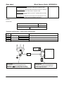
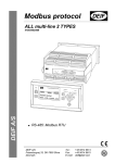
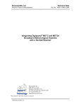
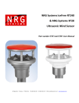
Wind sensor type WSS and WSS-L
DATA SHEET
Static sensor
•
•
Extreme temperatures
No moving parts
High-precision ultrasonic measurements
High resolution
•
•
o
Wind direction 1
wind speed 0,1 knot
Approval
•
GL, DNV, CCS, RS, GOST-R
Sea-water proof housing
Vibration tested up to 2.3g
Watertight
•
o
WSS operates down to -52 C
o
WSS-L is not recommended below 0 C
o
Both operates to +60 C
Heating element
•
WSS has built-in, automatically activated,
heating element to prevent ice
Wide power supply range
•
Robust design
•
•
•
•
•
Nominal 12V DC or 24V DC supply voltage
Interface
•
RS485 I/O using NMEA 0183 data protocol for
direct connection to WSDI-2 wind display, VDR
(voyage data recorder) or Dynamic Positioning
System.
According to IP66
Document no.: 4921250059D
Data sheet
Wind Sensor Static WSS/WSS-L
Technology
DEIF Static Wind Sensor Technology uses ultrasound
to determine horizontal wind speed and direction. The
WSS and WSS-L sensors have no moving parts so
they are free from the challenges posed by
conventional mechanical wind sensors (friction, inertia,
time constant, over-speeding, starting threshold). The
unique triangular design of the sensor array assures
accurate measurement of wind from all directions. The
WSS sensor is automatically heated when used in cold
climates. Finally, WSS/WSS-L sensors are
maintenance-free and do not require field calibration.
Versions
The wind sensor is available in two versions:
- WSS with built-in heating element to prevent ice
- WSS-L without heating
Applications
WSS/WSS-L are classified for residential, commercial
and light industry plus industrial environment.
The WSS sensor can be used in almost any conditions,
o
where the WSS-L is only specified down to 0 C, but it
will work far below that temperature as long as ice or
snow is not covering the sensor elements or obstructing
the sight between the elements. The WSS-L should
only be used in relatively warm geographic areas or in
applications where wind data is mainly for information
and not critical for operation or safety.
- The WSS or WSS-L can be directly connected to the
DEIF WSDI-2 display forming a superb wind system.
- Alternatively, it can be used with the former display –
WSDI – which required a WSI interface box.
Error flag
The WSS/WSS-L
continuously
evaluates
the
measurements, and if obstructions or incorrect
measurements are detected, an invalid flag is set in the
NMEA0183 message to indicate that data is invalid and
should not be used. This could be caused by a bird
landing on the sensor. As soon as the disturbance
disappears, the flag will be cleared and valid
measurements sent.
Customised setup
Forming part of a normal wind system, the WSS will not
need any setup. If the sensor is used for special
applications, there might be special needs, for example
storing data for automatic sensor alignment corrections.
Such special needs can often be accomplished by
sending control commands to the sensor via the RS485
interface, so please contact DEIF if you have special
needs like this.
- It forms part of the WSS upgrade kit used to replace
the old DEIF 879 dynamic wind sensor.
- Finally WSS or WSS-L can be used as precise standalone wind sensors in a system (e.g. a DP system).
Housing
The WSS is designed to withstand the hostile
environment onboard a ship.
The 1” stainless steel mounting rod with standard ¾”
pipe thread makes the mounting easy and secures
good earth connection through the hull of the ship.
Option
-
Interface
The WSS/WSS-L has a RS485 two-way interface with
communication following the NMEA 0183 protocol.
-
Supply
The WSS can be supplied from a DC supply of nominal
12…24V DC.
Cable
-
-
A VDR (voyage data recorder) can be
connected directly to the RS485 port.
Bird avoidance option, a needle cap to prevent
birds from landing on the sensor, disturbing
the measurements or damaging the ultrasound
elements.
WSS-shielded extension cable, variable length
from 1 to 300 meters.
IP67 connector kit, for use with extension
cable (for soldering).
IP66 connection box kit, for use with extension
cable.
2
The WSS is connected with a single 4 x 0.75mm
screened cable. Cable extension can be made by a
2
standard 4 x 0.75mm screened cable, e.g. UL2464
18AWG4C+AE, length max. 300 metres, the capacity
between each signal conductors should not excide
70nF. Twisted pair is recommended. (see options)
DEIF A/S
Page 2 of 5
Data sheet
Wind Sensor Static WSS
Technical specifications
Sensors are designed according to the standards below
Standards
12V or 24V DC
Power supply
(9.0…31.2V DC)
WSS-L and WSS with inactive heating element: < 0.1W
Power consumption
WSS with maximum heating < 15W
RS485 bus (I/O).
The bus should be terminated with 120 to 200 ohm for pure RS485
operation.
Combined RS485 (I/O) and NMEA0183 (I) operation:
A combination of up to ten RS485 (I/O) and one NMEA0183 listeners
Interface
NMEA 0183 ver. 2.x-3.0
can be connected to the WSS data interface at the same time.
The data line must be terminated with a 200 to 250 ohm resistor to
obtain > +/- 2.1V output necessary for a standard NMEA0183 input
circuit to work. The NMEA0183 input load must be < 2mA @ +/- 2V.
NOTE: A NMEA-buffer is recommended if connection of more than one
standard NMEA-input is needed.
NMEA0183:
$WIMWV – Wind speed and direction data
$WIXDR – Transducer Measurement Response
Data sentence
NMEA 0183 ver. 3.0
$WITXT – Error messaging
For details, see the Appendix to User's Manual, Wind measuring system,
document no. 4189350028.
Range:
0….116 KTS (0….60m/s)
Resolution:
0.1 Knots
Wind speed
Accuracy:
0…68 KTS: ±0.6 KTS or ±3%, whichever is greater
> 68 KTS: ±5%
o
Wind direction
Update interval
Start-up time
Connection
Mounting
Compass safety
distance
Protection
Relative humidity
Pressure
Temperature
Range:
0…. 360 continuously
o
Resolution:
1
Accuracy:
±3% in relation to wind direction
1 second
< 5 sec. from power on to valid data output
2
2 meter 4 x 0.75mm screened cable type UL2464
18AWG/4C+DW+AL/MY+Jacket.
The 2m cable is fixed mounted on the sensor and is open-ended.
¾” pipe thread: Outer diam: 1.04 inch (26.4mm), 14 threads per inch.
0.2 meter (8 inch)
IEC 945 and EN 60945
IP66
0…. 100%
600…1100hPa
WSS operating range:
-52…+60°C (class approved for: -25…+60°C)
WSS-L operating range: 0…60°C (see note)
Storage (both):
-60…+70°C
IEC 529 and EN 60529
EN/IEC 60068-1/2
EN 60051
Note: WSS-L has no automatic heating element to prevent ice, the
sensor will work below 0°C, but it will depend on weather conditions.
Vibration test
Safety
EMC
Housing
3…13.2Hz:
2mm (peak-peak)
13.2…100Hz: 0.7g
3…15Hz:
+ 2.5mm (peak)
15…50Hz:
2.3g
Cat.III, poll.dg.2, 550VAC rms, 50Hz, 1 minute,
CE-marked for industrial environment
Wind sensor housing: Polycarbonate +10% glass fibre
Mounting tap: Corrosion-resistant stainless steel
Weight
Dimensions,
cardboard box
0.8 kg
Approvals
Type-approved according to:
DEIF A/S
EN 60945,
EN/IEC60068-2-6 and
DNV Class A
GL curve 4 for masts
EN 61010-1
EN 61000-1-1/2/3/4
UL94 V0
450 x 315 x 230
GL, DNV, CCS, RS and
GOST-R
Page 3 of 5
Data sheet
Accessories
Wind Sensor Static WSS/WSS-L
IP66 Connection box kit: IP66 Connection box w/cable glands and
screw terminals to extend the sensor cable with an extension cable.
IP67 Connector kit: water tight male and female connector for soldering
to respectively the sensor cable and the extension cable.
2
Extension cable: 1 to 300 meters 4x0.75mm shielded cable (1m steps)
DEIF id.no.1020230016.
Bird avoidance kit: Spike kit to prevent birds from interrupting the wind
measurements or in worst case from damaging the sensor.
Labels
Product label:
WSS
CE logo
SN:
Disposal icon
DEIF logo
Bar code + item number
Terminals and function – cable colours and function
Cable
colour
Black
Red
Orange
Brown
Shield
Function
Note
+
A
RS485 comm.
B
Electrical shielding of data signal
DC supply voltage for the wind sensor
Supply voltage
Wind speed and direction data output
See warning below.
DC power source
+
WSDI-2
1.
2.
….
7.
8.
9.
Conn.
kit
(Optional)
T
IMPORTANT!
The stainless steel mounting base on the
WSS/WSS-L must be connected to the ship's
metal hull or another good ground connection!
DEIF A/S
IMPORTANT!
The data bus must be terminated with a
resistor (see technical spec. above) to
secure stable operation!
Page 4 of 5
Data sheet
Wind Sensor Static WSS/WSS-L
Unit dimensions, WSS and WSS-L
114.0
49.5
82.4
149.8
198.0
127.0
All dimensions in mm
¾” pipe thread:
Outer diam: 1.04 inch (26.4mm), 14 threads per inch.
Order specifications
Examples: WSS
WSS-L upgrade kit
Example - ordering a wind system example:
WSDI-2 FWD
WSS
Connector box kit
Extension cable 80 meter
Due to our continuous development we reserve the right
to supply equipment which may vary from the described.
DEIF A/S, Frisenborgvej 33
DK-7800 Skive, Denmark
Tel.: +45 9614 9614, Fax: +45 9614 9615
E-mail: [email protected], URL: www.deif.com