1
FormsMaster 8000 Series
High Performance
Serial Matrix Printers
Operator’s Manual
©Printek, Inc. 1997
1517 Townline Road
Benton Harbor, MI 49022
616-925-3200
Part Number 4339 Rev. A
This equipment has been tested and found to comply with the limits for a Class A Digital
Device, pursuant to Part 15 of the FCC Rules. These limits are designed to provide
reasonable protection against harmful interference when the equipment is operated in a
commercial environment. This equipment generates, uses, and can radiate radio
frequency energy and, if not installed and used in accordance with the instruction manual,
may cause harmful interference in which case the user will be required to correct the
interference at his own expense.
The user is cautioned that any changes or modifications not expressly approved by
the party responsible for compliance could void the user's authority to operate the
equipment.
This digital apparatus does not exceed the Class A limits for radio noise emissions
as set out by the ICES-003 standard, of the Canadian Department of
Communications.
Cet appareil numérique n’émet pas de bruits radioélectroiques depassant les limites
de Classe A prescrites dans la norme NMB-003 Édictée par le Ministre des
Communications du Canada.
Acknowledgments:
IBM, Proprinter, and IPDS are registered trademarks of International Business
Machines Co.; DEC is a registered trademark of Digital Equipment Corporation;
Epson is a registered trademark of Seiko Epson; QMS is a registered trademark of
Quality Micro Systems, Inc.; IGP is a registered trademark of Printronix Corp.;
Printek is a registered trademark of Printek, Inc.
Specifications are subject to change without notice.
ii
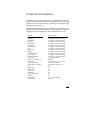
Table of Contents
Introduction
Models and Options
Manual Contents
1
1
Getting Started
Installation
Interface Set Up
Installing The Ribbon Cartridge
Why Use Only Printek® Brand Ribbons
Ribbon Installation
Loading Paper
FormsMaster 8000 Single Tractor Model
FormsMaster 8003 TriTrak™ Model
Printer Self-test
3
4
8
8
10
13
13
14
17
Daily Operation
Introduction
Control Panel Features
LCD Display and Online Indicator
Push Buttons
Selecting and Loading Forms
Selecting a Form Already Loaded in the Tractors
Loading a New or Different Form In the Tractors
Ejecting and Tearing Off a Form
Installing a New Ribbon Cartridge
Aligning Print
Common Error Conditions
Check Paper
No Paper to Load
Too Much Paper to Unload
Selected Form is not Loaded
No Ribbon or Wrong Ribbon
Ribbon Lid Open
19
20
20
22
25
25
25
30
32
34
36
36
37
37
37
37
37
iii
Paper Door Open
Change Ribbon
38
38
Printer Configuration
Introduction To Setup
Setup Buttons
Entering Setup
Using the MENU Button
Using the SUBMENU Button
Using the ITEM and VALUE Buttons
Exiting Setup
Forms Menu
Forms Menu Items
Interface Menu
Automatic Port Switching
RS-232C Serial Interface Items
Parallel Interface Items
EtherLink LAN Interface Items
Coaxial/Twinaxial Interface Items – Coax Configuration
Coaxial/Twinaxial Interface Items – Twinax Configuration
IPDS Coax Interface Items
IPDS Twinax Interface Items
Imager and ImagerPlus Interface Items
Options Menu
Test Menu
Using the Built In Demos
39
39
40
40
40
41
41
42
43
49
49
51
55
57
59
63
66
71
72
78
82
83
Form Construction and Layout Tips
Form Construction
Form Layout Considerations
85
85
Maintenance and Troubleshooting
Messages
Preventive Maintenance
Obtaining Service
87
88
88
Advanced Setup Features
89
Using Remote Setup
91
Using the Optional Setup Module
99
iv
Printer Reset Conditions
105
Control Code and Escape Sequence Summaries
ANSI X3.64 Emulation
Epson FX Emulation
IBM Proprinter Emulation
LA-120 Emulation
Simple TTY Emulation
Printek Emulation
107
108
110
112
114
115
ASCII Character Tables
117
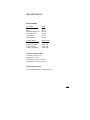
Specifications
123
Glossary of Terms
129
v
Introduction
Thank you for purchasing a Printek FormsMaster 8000 Series Printer.
This printer has been designed to provide years of service handling your
most demanding printing requirements.
The FormsMaster 8000 Series printers offer higher throughput than all
other printers in its class. In addition, an easy to use front panel combined
with the ability to store ten different form configurations makes handling
multiple forms as simple as a button press for the operator.
Models and Options
The FormsMaster 8000 and the FormsMaster 8003 differ only in the
number of tractor paths available, one path or three.
Options available for both models include:
Coaxial and Twinaxial Interface
Coaxial IPDS Interface
Twinaxial IPDS Interface
EtherLink Interface
Imager Bar Code Coprocessor
ImagerPlus Bar Code Coprocessor
Print Stand (required for reduced sound levels)
Internal FormsCutter
Setup Module
Manual Contents
•
Getting Started provides instructions for installation, setting up the
computer interface, installing the ribbon cartridge, loading paper,
and performing a printer self-test.
•
Daily Operation provides more detailed descriptions of the
features that are used most frequently. These include the “every
day” buttons and indicators on the control panel, selecting or
1
I N T R O D U C T I O N
loading new forms, ejecting forms, changing the ribbon cartridge,
aligning print with preprinted forms, and causes for common error
conditions.
•
Printer Configuration provides detailed information on how to
use Setup to permanently store parameters for each of the ten
forms, parameters for the standard and optional interfaces, and
parameters for other options.
•
Specifying Forms provides tips for form construction and layout.
•
Maintenance and Troubleshooting lists more serious error
messages than discussed in the Daily Operation section,
preventive maintenance, and how to obtain service.
•
Advanced Setup Features provides information on how to set
menu security.
•
Using Remote Setup describes how to “set up” default parameters
from a host computer.
•
Using the Setup Module describes how the optional Setup Module
can be used to copy Setup parameters from one printer to another.
•
Printer Reset Conditions describes the state of the printer after
power up or reset.
•
Control Code and Escape Sequence Summaries lists the
commands supported for each printer emulation.
•
ASCII Character Tables show the characters for each character
set.
•
Specifications lists the operating ranges and ratings of the printer.
•
Glossary of Terms provides definitions for terms used in this
manual.
2
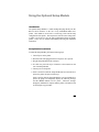
Getting Started
This chapter will use the fewest possible steps to get the first time user up
and running quickly. You will be guided through the following steps:
Finding a suitable location and installing the printer
Setting up a host interface if necessary
Installing the ribbon cartridge
Loading paper
Performing a printer self-test
INSTALLATION
Before installation, a suitable site must be chosen. Suitable sites include
offices, computer rooms, and most factory environments. The Printek
FormsMaster printers have been designed to be rugged, heavy duty printers.
As such, they will handle most harsh environments, but should not be
placed in direct sunlight or in areas that will exceed the rated temperature,
humidity, or power requirements. For details, refer to “Specifications” on
page 123.
Once a site has been selected, the printer should be placed on a Printek Print
Stand. The Printek print stand is especially recommended for the
FormsMaster 8003 and is required to meet the low noise rating of the
printer. Of course, another sturdy print stand or table with a slotted top for
feeding paper into the bottom of printer may be used.
The print stand should be located in an area large enough to provide easy
access to both the front of the printer and the rear for accessing printed
output. Unpack the printer as described in the “FormsMaster 8000
Unpacking Instructions” and place the printer on the print stand.
Note: Placing the printer on the print stand is best accomplished with two
people. Proper lifting technique should be observed.
3
G E T T I N G
S T A R T E D
Caution: Before connecting or turning on power, make sure that all
shipping materials have been removed. These materials include
a cable tie that secures the print head carriage (open ribbon lid
to access) and two cardboard tubes placed over the tractor
shuttle shafts in the FormsMaster 8003 (open paper door on
front of unit to access).
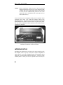
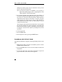
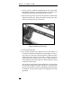
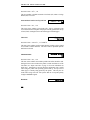
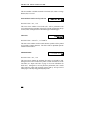
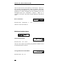
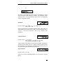
Next, connect the power cord supplied with the printer to the printer and an
appropriate power outlet. Now connect the computer cable(s) to the
appropriate interface. The picture below shows the location of the standard
Parallel and RS-232C interface connectors on the rear panel of the printer.
The area where an optional CX/TX, ICX, ITX, or LAN interface may be
installed is also indicated.
Interface Connectors on Rear of Printer
INTERFACE SET UP
Depending upon which interface is being used to connect the printer to the
host computer, some set up may or may not be required. Regardless of
which interface is used, the FormsMaster 8000 will automatically detect
which port is receiving data and make that port active. This is true of the
standard parallel or serial ports and any optional interface that may be
4
G E T T I N G
S T A R T E D
installed. For more information, see “Automatic Port Switching” on page
49.
The factory default settings for each interface should work well for most
installations. However, the following paragraphs provide some basic
information about each interface and also refer to the page number in the
Configuration chapter where all the details for each interface are described.
If you need to make changes to the default settings, please refer to
“Introduction to Setup” on page 39 for instructions on how to access the
printer’s Setup menus.
Once you are comfortable that the interface settings match those required
by your computer, proceed to the next section, “Installing the Ribbon
Cartridge” on page 8.
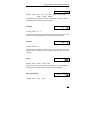
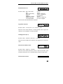
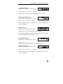
RS-232C Serial Interface
This interface uses a 25 pin “D” connector as described below. The default
settings are 9600 baud, 8 data bits, 1 stop bit, and no parity with hardware
handshake on pin 11. The default printer emulation is Epson. For a
complete description of all the default settings for this interface, refer to
page 51.
Pin
1
2
3
4
5
6
7
8
11
20
Signal
Chassis ground.
Transmit data. (Printer output).
Receive data. (Printer input).
Request to send (set). (Printer output).
Clear to send (ignored). (Printer input).
Data set ready (ignored). (Printer input).
Signal ground.
Carrier detect (ignored). (Printer input).
Printer busy. (Printer output).
Data terminal ready. (Printer output).
RS-232C Serial Interface Connector.
5
G E T T I N G
S T A R T E D
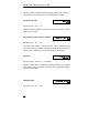
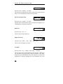
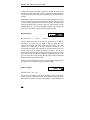
Parallel Interface
This interface uses the standard 36 pin parallel connector as shown below.
The default printer emulation is Epson. For a complete description of all
the default settings for this interface, refer to page 55.
Pin Signal
Pin Signal
____________________
_______________________
1 DATA STROBE
19 DATA STROBE RTN
10 ACKNOWLEDGE
28 ACKNLG RETURN
2 DATA 1
20 DATA 1 RETURN
11 BUSY
29 BUSY RETURN
3 DATA 2
21 DATA 2 RETURN
12 PAPER ERROR
4 DATA 3
22 DATA 3 RETURN
13 SELECT
________________
14 AUTO FEED
5 DATA 4
23 DATA 4 RETURN
16 ±0V
6 DATA 5
24 DATA 5 RETURN
18 +5V at 200mA Max.
7 DATA 6
25 DATA 6 RETURN
8 DATA 7
26 DATA 7 RETURN
17 CHASSIS GROUND
______
31 INIT
30 INIT RTN
_________
32 FAULT
35 +5V LOGIC HIGH
______________
9 DATA 8
27 DATA 8 RETURN
36 SELECT IN
Parallel Interface Connector
6
G E T T I N G
S T A R T E D
EtherLink Interface
This interface uses a standard RJ-45 connector and the default printer
emulation is Epson. For a complete description of all the default settings
for this interface, refer to page 57. For additional software installation and
operational information, please refer to the Axis manuals shipped with the
unit (disregard the Axis physical installation information).
Coax/Twinax Interface
This interface automatically sets itself for either Coax Mode or Twinax
Mode depending upon which adapter cable (coax BNC or twinax smart
“T”) is attached to the 15 pin “D” connector when the printer is powered
on. Only the choices for the detected mode are available in the Setup
menus.
For Coax Mode, the default emulation is for a 3287 printer. For a complete
description of all the default settings for the Coax interface, refer to page 59.
For Twinax Mode, the default emulation is for a 4214 printer. For a
complete description of all the default settings for the Twinax interface,
refer to page 63.
IPDS Coax Interface
This interface uses a coax BNC adapter connected to the 15 pin “D”
connector on the rear of the printer. The default values should work in most
cases. For a complete description of all the default settings for this
interface, refer to page 66.
IPDS Twinax Interface
This interface uses a twinax smart “T” adapter connected to the 15 pin “D”
connector on the rear of the printer. The default values should work in most
cases. For a complete description of all the default settings for this
interface, refer to page 71.
7
G E T T I N G
S T A R T E D
INSTALLING THE RIBBON CARTRIDGE
The Printek FormsMaster printer has been designed to make installing
Printek brand ribbons a simple, clean process. Unlike other printers, there
is no need to touch the ribbon fabric or deal with difficult to position ribbon
guides. The following sections explain why the use of Printek brand
ribbons should be important to you and will guide you through installing
the ribbon cartridge.
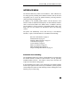
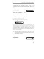
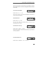
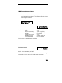
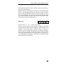
Why Use Only Printek® Brand Ribbons
REORDER NUMBER 90729
FOR NEAREST DISTRIBUTOR
CALL 1-800-368-4636
Printek® Brand Ribbon Label
Printek brand ribbons can be identified by the above label on each ribbon.
There are many reasons to use only Printek brand ribbons in your
FormsMaster 8000 series printer. First of all, using only Printek brand
ribbons will automatically extend the print head warranty to two years
instead of one year.
The reason this is possible is that Printek brand ribbons are manufactured to
much higher quality standards than those offered by other manufacturers.
This provides not only longer print head life, but also longer ribbon life…
23 million characters as compared to only 15 million characters from some
generic ribbons.
Remember that using only Printek brand ribbons is important because the
wear that is started and the contamination that remains from even one
inferior ribbon will continue to damage the print head. Also, damage to
other printer components which is caused by the use of non-Printek ribbons
will not be covered by the printer’s warranty.
8
G E T T I N G
S T A R T E D
Using inferior ribbons would be like using poor quality fuel in your
automobile. Premature engine failure and poor performance leading up to
the failure would be the best you could expect.
Other useful features available only with the use of Printek brand ribbons
are that the printer will not allow printing if a ribbon is not installed, and the
printer will alert the operator when a ribbon needs to be changed.
9
G E T T I N G
S T A R T E D
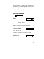
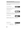
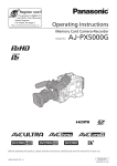
Ribbon Installation
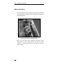
1. Open the ribbon lid on top of the printer and position the print head
for ribbon loading by lifting the ribbon loading handle as indicated in
the following picture.
Opening the Ribbon Loading Handle
2. Remove the new ribbon from its plastic bag and make sure the
ribbon fabric is taut by turning the knob on top of the ribbon
cartridge in a counterclockwise direction as indicated by the arrow
on the cartridge.
10
G E T T I N G
S T A R T E D
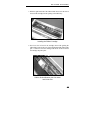
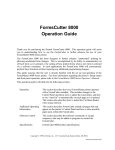
3. With the right hand end of the ribbon tilted down, insert the tab on
the end of the cartridge into the opening in the ribbon tray.
Installing the Ribbon Cartridge
4. Now lower the left end of the cartridge down while guiding the
ribbon fabric between the nose of the print head and the ribbon guide
pins. Continue to lower the cartridge until the tab on the left end of
the cartridge snaps into place.
Ribbon Guided Between the Print Head
and Guide Pins
11
G E T T I N G
S T A R T E D
5. Finally, lower the ribbon loading handle to its original position.
Closing the Ribbon Load Handle
6. Close the ribbon lid on top of the printer.
12
G E T T I N G
S T A R T E D
LOADING PAPER
When shipped from the factory, the basic configuration for all ten forms is
an eleven inch form, six lines per inch, and ten characters per inch. If the
forms you are loading do not match these requirements, please refer to the
“Printer Configuration” chapter on page 39 and review the “Using Setup”
and “Forms Menu” sections.
Please refer to the appropriate section below for loading paper in the
FormsMaster 8000 or FormsMaster 8003.
FormsMaster 8000 Single Tractor Model
1. Make sure the printer is powered on and that the printer is off line
(ONLINE indicator flashing red).
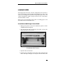
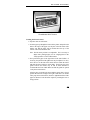
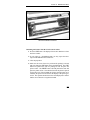
2. Lift open the paper door on the front of the printer to expose the
paper feed tractors as shown below.
FormsMaster 8000 Tractors
3. Open the doors on each tractor.
4. Feed the paper up through the bottom of the printer and position the
holes in the edge of the paper over the pins in the left tractor while
13
G E T T I N G
S T A R T E D
making sure that the paper will not extend above the top of the
tractors. Then close the tractor door.
Note: The left tractor position is not adjustable. If it is necessary to
adjust where printing begins, refer to “Aligning Print” in the
“Daily Operation” section of this manual.
5. Now position the paper in the right tractor in the same fashion. If
necessary, the position of the right tractor may be adjusted. To do so,
move the lever on the side of the tractor down to unlock the tractor
and slide the tractor sideways on the shafts. If necessary, the paper
guides between the tractors may be slid in either direction to
accommodate the form width. Make sure that the guides are spaced
evenly between the tractors.
After the paper is placed in the tractor and the door is closed, position
the tractor far enough to the right so that there is no buckle in the
paper between the tractors, but not so tight that the holes in the paper
are distorted. Lock the tractor in place by returning the lever to the
up position.
6. Close the paper door.
7. Press the LOAD button.
8. Place the printer on line by pressing the ONLINE button.
FormsMaster 8003 TriTrak™ Model
The following instructions will guide you through loading all three tractor
paths.
1. Make sure the printer is powered on and that the printer is off line
(ONLINE indicator flashing red).
2. Press the UNLOAD button to move the tractor shuttle forward to the
load position.
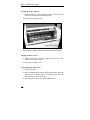
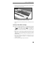
3. Lift open the paper door on the front of the printer to expose the
paper feed tractors as shown in the following picture.
14
G E T T I N G
S T A R T E D
FormsMaster 8003 Tractors
Loading the Front Tractors
4. Open the doors on each tractor.
5. Feed the paper up through the bottom of the printer and position the
holes in the edge of the paper over the pins in the left tractor while
making sure that the paper will not extend above the top of the
tractors. Then close the tractor door.
Note: The left tractor position is not adjustable. If it is necessary to
adjust where printing begins, refer to “Aligning Print” in the
“Daily Operation” section of this manual.
6. Now position the paper in the right tractor in the same fashion. If
necessary, the position of the right tractor may be adjusted. To do so,
move the lever on the side of the tractor down to unlock the tractor
and slide the tractor sideways on the shafts. If necessary, the paper
guides between the tractors may be slid in either direction to
accommodate the form width. Make sure that the guides are spaced
evenly between the tractors.
After the paper is placed in the tractor and the tractor door is closed,
position the tractor far enough to the right so that there is no buckle
in the paper between the tractors, but not so tight that the holes in the
paper are distorted. Lock the tractor in place by returning the lever to
the up position.
15
G E T T I N G
S T A R T E D
Loading the Center Tractors
7. Tilt the front tractors forward by pulling the green lever on the right
hand side of the front tractor assembly forward.
8. Repeat steps 4 through 6 above.
Front Tractors Tilted Forward for Access to Center Tractors
Loading the Rear Tractors
9. Tilt the center tractors forward by pulling the green lever on the
center tractor assembly forward.
10. Repeat steps 4 through 6 above.
Selecting Which Form to Print
11. Close the paper door.
12. Press the FORM SELECT button until the desired form is displayed
and then press the LOAD button. The printer will now move the
selected form into position for printing.
13. Place the printer on line by pressing the ONLINE button.
16
G E T T I N G
S T A R T E D
PRINTER SELF-TEST
The printer performs many self diagnostics each time power is turned on. If
you wish to perform an actual printing test, use the following steps.
1. Make sure the printer is powered on with ribbon and paper loaded.
2. Take the printer off line (the ONLINE indicator will be flashing red).
3. Press the SETUP/MENU button four times to display TEST MENU on
the front panel.
4. Press either of the ITEM buttons until Test Mode is displayed on the
top line.
5. Press either of the VALUE buttons until Barber Pole is displayed on
the bottom line.
6. Press the ONLINE button.
7. The printer will now exit Setup and begin printing a rotating
character pattern. To stop or restart printing the test pattern, press the
ONLINE button.
8. To take the printer out of the test mode, stop the test by pressing the
ONLINE button.
9. Press the SETUP/MENU button four times to display TEST MENU.
10. Press either of the ITEM buttons until Test Mode is displayed on the
top line.
11. Press either of the VALUE buttons until Off is displayed on the
bottom line.
12. Press the ONLINE button.
17
Daily Operation
INTRODUCTION
This chapter describes how to use the “everyday” features of the
FormsMaster 8000. The items covered are:
Control Panel Features – describes the most commonly used
features of the printer’s control panel.
Selecting and Loading Forms – describes how to insert paper
or forms into the tractors and how to inform the
printer of which forms are “loaded”.
Ejecting and Tearing Off a Form – describes how to remove
printed documents from the printer.
Installing a New Ribbon Cartridge – describes first time
installation of the ribbon cartridge.
Aligning Print – describes how to precisely align where data is
printed on a form.
Common Error Conditions – describes errors that may occur
during normal printing operations.
19
D A I L Y
O P E R A T I O N
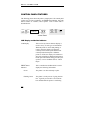
CONTROL PANEL FEATURES
The following picture shows the printer’s control panel. The control panel
consists of a two line LCD display, an ONLINE status indicator, nine push
button switches or “buttons”, and a speaker. Each of these items is
described below
SETUP
MENU
ALIGN
PRINT
SUBMENU
LCD
DISPLAY
ITEM
FORM
SELECT
FORM
FEED
VALUE
UNLOAD
LOAD
ON LINE
Control Panel
LCD Display and Online Indicator
LCD Display
This two line by sixteen character display is
used to convey several types of information.
When the printer is on line and printing, or
ready to print, the display will show the
currently selected tractor path and the form
currently loaded in that path. When the
printer is off line, the display will continue to
show this information, additional information
based upon other buttons being pressed by the
operator, or error conditions such as “Check
Paper”.
ONLINE Status
Indicator
This is a multicolored LED which is used to
display the following information:
20
Green:
The printer is on line and ready to print.
Flashing Green:
The printer is in the process of going back on
line. Typically occurs after a new form has
been loaded while the printer is confirming
D A I L Y
O P E R A T I O N
which forms are loaded in the tractors.
Flashing Red:
The printer is currently off line and cannot
print. This may be due to the operator taking
the printer off line or the printer may have
detected an error condition, such as running
out of paper, which requires operator
intervention. If due to an error condition, the
cause of the error will periodically be shown
on the LCD display. After the cause of an
error condition has been resolved, press the
ONLINE button to clear the error. This will
also place the printer back on line and allow
printing to resume.
Yellow:
The printer is in the process of exiting the
Setup mode and saving Setup values, or the
printer is currently busy performing an
operation with the optional Setup Module.
Flashing Yellow:
The user has pressed the SETUP button and
entered the Setup mode (may be exited by
pressing the ONLINE button after the desired
changes have been made). For more
information, see the chapter on “Printer
Configuration”.
Speaker
This device produces various tones to alert the
operator when different error conditions
occur. It may also be used to produce a tone
when a bell character (ASCII BEL) is received
from a host computer.
21
D A I L Y
O P E R A T I O N
Push Buttons
ONLINE
This button toggles the printer between the on
line and off line state. When the printer is on
line, it may be printing or may begin printing
at any time. To stop the printing or prevent
printing from starting, use this button to take
the printer off line (see “ONLINE Status
Indicator” above). The printer must be off
line in order to use the other control panel
buttons.
This button is also used to place the printer
back on line following any error condition
(ONLINE indicator is flashing Red), such as
paper out. When pressed to go on line, the
printer will first attempt to clear any errors.
For example, if there is a paper out condition,
the printer will attempt to load the form in the
currently selected tractors and, if successful,
go on line.
FORM FEED
/LOAD
This button performs a number of different
form feeding functions. The printer will
automatically select the correct function to
perform based upon the current position of the
form.
LOAD:
•
Loads the form that has been selected
with the FORM SELECT button.
If a the selected form is already
recognized as “loaded” in the tractors, the
printer will position the tractors if
necessary (FormsMaster 8003) and
advance the form to the print position.
If the selected form is not currently
considered to be loaded in the tractors
22
D A I L Y
O P E R A T I O N
(display shows <Not Loaded>), this
button will change the status of this form
to “loaded” and the bottom line of the
display will show the path(s).
FORM FEED:
FORM SELECT
/UNLOAD
•
If a form is currently loaded and perhaps
partially printed, this button will advance
the bottom of the current form to the tear
bar so that it may be torn off.
•
If a form has already been advanced to the
tear bar, this button will advance the next
form to the tear bar.
This button is used to access up to ten
different forms which have been previously
configured with the Setup menus (see the
chapter on Printer Configuration for more
information).
When this button is pressed, one of two
functions will be performed.
UNLOAD:
•
If a form is currently in position to be
printed, this button will pull the form
down until the top of the form is below
the top of the tractors. In the
FormsMaster 8003 this will also cause the
tractor shuttle to move forward for easy
access to all tractors.
FORM SELECT:
•
If the form has already been pulled down
to the tractors as described above, this
button will cycle through all the available
form choices. Forms which are not
considered to be “loaded” in the tractors
will flash <not loaded> on the bottom
23
D A I L Y
O P E R A T I O N
line of the display. In the
FormsMaster 8003 the not loaded
message will alternate with the tractor
path assigned to that form. For more
information, see the following section on
“Selecting and Loading Forms”.
ALIGN PRINT
This button will access the horizontal and
vertical print adjustment settings for the
currently selected form.
When ALIGN PRINT is pressed, the horizontal
adjustment is shown first. Pressing the VALUE
buttons will move the print position on the
line left or right by 0.01 inches for each press
of a button as indicated on the display. The
arrows to the side of the number will indicate
the direction the print will be moved.
To access the vertical adjustment, press either
ITEM button. Pressing the VALUE buttons will
now move the print up or down on the page by
0.01 inches for each press of a button as
indicated on the display. The arrow to the
right of the number will indicate the direction
the print will be moved.
For a more detailed description, see “Aligning
Print” later in this chapter.
SETUP
24
This button is used to set up the various
operating parameters of the printer for forms,
interfaces, etc. This button is not used on a
daily basis. For more information see the
chapter on “Printer Configuration”.
D A I L Y
O P E R A T I O N
SELECTING AND LOADING FORMS
Note: A form is not considered “loaded” by merely placing the
form in the tractors. To prevent printing on the wrong form,
the printer must be made aware of what form(s) are
currently loaded. When a new form is placed in the tractors,
the form must be “loaded” using the control panel as
described in the next section, “Loading a Different Form in
the Tractors”.
Selecting a Form Already Loaded in the Tractors
To select a form that is already loaded in the tractors, take the printer off
line and press the FORM SELECT button until that form is displayed (a form
that is not considered to be loaded will flash <Not Loaded> on the bottom
line of the display). The form selection will be displayed as FORM 0
through FORM 9 or as the actual name of the form if that has been set up.
To position the form for printing, you may press the FORM FEED button
which will position the form, or you may press the ONLINE button which
will both position the form and place the printer on line.
Loading a New or Different Form In the Tractors
This section describes how to “load” a form in the tractors. This involves
physically placing the paper or form in the tractor mechanism and then
informing the printer that the new form is present.
Select the Form to be Loaded
1. Take the printer off line by pressing the ONLINE button.
ONLINE indicator should now be flashing red.
The
2. Press the FORM SELECT/UNLOAD button. This will move the current
form from the print position down to the tractors for removal. In the
25
D A I L Y
O P E R A T I O N
case of the FormsMaster 8003 this will also move the shuttle forward
for easy access to all tractor paths.
3. Continue to press the FORM SELECT button until the desired form
name is shown on the top line of the display. The form name will be
FORM 0 through FORM 9 or the actual name of the form if the
name has been set in Setup. If the desired form is not considered to
be “loaded” by the printer, <Not Loaded> will flash on the bottom
line of the display. In the case of the FormsMaster 8003 the not
loaded message will alternate with the path(s) that this form is to be
loaded in.
Loading the Form in the Tractors
4. Open the paper door on the front of the printer. This will provide
access to the tractors as shown below. If your printer is a
FormsMaster 8000, only one set of tractors will be available and you
may skip ahead to step 6.
FormsMaster 8003 tractors
5. Depending upon which path(s) the new form is to be placed in, you
may need to tilt the front and/or center tractors forward as shown.
26
D A I L Y
O P E R A T I O N
FormsMaster 8003 with front and center
tractors tilted forward.
6. Open the tractor doors and remove the old form.
FormsMaster 8003 with rear path empty
27
D A I L Y
O P E R A T I O N
7. If the new form is a different width than the previous form, unlock
the right tractor and move it to approximately the new position. Note
that the left tractor position is fixed and may not be moved.
8. Place the left edge of the new form in the left tractor with the holes
aligned with tractor pins. Make sure that the top edge of the form
does not extend above the top of the tractors.
Paper positioned in left tractor.
9. Close the left tractor door.
10. Now position the paper in the right tractor in the same fashion. If
necessary, the position of the right tractor may be adjusted. To do so,
move the lever on the side of the tractor down to unlock the tractor
and slide the tractor sideways on the shafts. If necessary, the paper
guides between the tractors may be slid in either direction to
accommodate the form width. Make sure that the guides are spaced
evenly between the tractors.
After the paper is placed in the tractor and the door is closed, position
the tractor far enough to the right so that there is no buckle in the
paper between the tractors, but not so tight that the holes in the paper
are distorted. Lock the tractor in place by returning the lever to the
up position.
28
D A I L Y
O P E R A T I O N
New form loaded in tractors
Informing the Printer That the New Form is Loaded
11. Press the LOAD button. The display will now show that the new form
has been “loaded”.
12. If your printer is a FormsMaster 8003 you may repeat the above
steps to load additional forms at this time.
13. Close the paper door.
14. Make sure the correct form to be positioned for printing is selected
and press either the LOAD button or the ONLINE button. The LOAD
button will position the form for printing but will not place the
printer on line. The ONLINE button will both position the form and
place the printer on line. Note that the first time the printer is placed
on line after a new form is loaded, the form(s) currently known to be
loaded by the printer will scroll across the display as the printer goes
on line. The operator should observe the forms displayed to confirm
that the correct forms are recognized as loaded.
29
D A I L Y
O P E R A T I O N
EJECTING AND TEARING OFF A FORM
When most print jobs complete, they will command the paper to be
positioned at the top of the next form so that the printer is ready for the next
job. This is, however, dependent solely upon how the programmer chose to
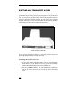
write your particular application software. If your software does position
the paper at the top of the next form, the printer will automatically position
the form at the tear bar as shown in the following picture.
Bottom of form at tear bar
If your form is positioned as shown, you may skip the next section on
positioning and proceed with “Tearing off a Form”.
Positioning the Form for Tear Off
1. If your print job has completed and the form is not positioned as
shown above, take the printer off line by pressing the ONLINE
button (indicator will change from green to flashing red).
2. Press the FORM FEED button. This will automatically position the
form at the tear bar and you may tear off the form as described
below.
30
D A I L Y
O P E R A T I O N
Tearing off a Form
1. Make sure the printer is off line (indicator flashes red when off line)
by pressing the ONLINE button if necessary. This will prevent the
printer from pulling the paper down to start printing the next job
while you are tearing off this one.
2. Pull the paper toward the front of the printer and toward one side of
the printer as shown.
Tearing off a form
3. Place the printer back on line with the ONLINE button (indicator
changes to green). The form will automatically be pulled down into
position for printing the next time the printer receives data to be
printed.
31
D A I L Y
O P E R A T I O N
INSTALLING A NEW RIBBON CARTRIDGE
Removing the Old Ribbon Cartridge
1. Open the ribbon lid on top of the printer and position the print head
for ribbon loading by lifting the ribbon loading handle as indicated in
the following picture.
Opening the Ribbon Loading Handle
32
D A I L Y
O P E R A T I O N
2. Grasp the left end of the ribbon cartridge and lift it up and toward the
rear of the printer as shown below
Removing the Old Ribbon Cartridge
3. Lift the right end of the ribbon and remove the ribbon from the
printer.
Installing the New Ribbon Cartridge.
Note: The use of Printek brand ribbons is recommended for increased
ribbon life and print head life. The use of only Printek brand ribbons
is required for the extended print head warranty. For details, see
“Why Use Only Printek Brand Ribbons” in the “Getting Started”
chapter.
4. Remove the new ribbon from its plastic bag and make sure the
ribbon fabric is taut by turning the knob on top of the ribbon
cartridge in a counterclockwise direction as indicated by the arrow
on the cartridge.
5. Install the new ribbon by reversing the above removal process. For a
more detailed installation description, see “Installing the Ribbon
Cartridge” on page 8
6. Close the ribbon lid and place printer back on line.
33
D A I L Y
O P E R A T I O N
ALIGNING PRINT
When a new form is loaded into the printer for the first time, it may be
necessary to adjust where printing begins. This depends upon how the
software that controls the printing was written. If the software was written
to perform its own character and line spacing relative to the edges of the
form, then adjustment may not be necessary. If the print position needs to
be adjusted, the following discussion will describe how this is
accomplished. Note that the alignment for the selected form is permanently
stored in the printer’s memory and does not have to be readjusted each time
the form is loaded.
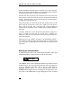
To align print on a particular form, select that form with the FORM SELECT
button and then press the ALIGN PRINT button. If the form selected is
named “Invoices”, the display would now show the following.
Aligning Print
On INVOICES
After a short time, the display would change to show that you can now
MOVE PRINT left or right. Be sure to remember that you are moving where
the print is placed on the page.
MOVE Left/Right
PRINT
←0.00”→
The VALUE buttons will move the print left or right in 1/100th inch
increments. Note that the left and right arrows will change according to
which way the print has been moved from the normal print position. The
maximum distance print may be moved is 9.99 inches in either direction.
To move the print vertically on the page, press either of the ITEM buttons
and the display will change to the following.
MOVE
PRINT
34
Down/Up
0.00” ↕
D A I L Y
O P E R A T I O N
The VALUE buttons will move the print down or up in 1/100th inch
increments. Note again that the arrow will change according to the
direction the print is to be moved from the normal print position. The
maximum distance print may be moved is 9.99 inches in either direction.
Example
In this example, a number needs to be printed in a box on a preprinted form.
This form could be a packing list, an invoice, or a check. The first time the
page is printed, the number misses the box as shown below.
12345
In this case, the print needs to be moved to the right and down. To
accomplish this, press ALIGN PRINT and access the Left/Right option.
First move the print to the right using the VALUE buttons. It appears that the
text needs to move about three characters. If the text is being printed at 10
cpi (characters per inch), this would be 0.30 inches. After making this
adjustment the display would look as follows.
MOVE Left/Right
PRINT
0.30”→
If you were to print this form now, it would appear as follows, showing that
the print still needs to be moved down.
12345
To move the print down, access the Down/Up option by pressing either of
the ITEM buttons. It appears that the print needs to be moved down nearly
the height of the characters. These characters are approximately 0.10
inches tall, so move the print down about 0.08 inches. The display should
look as follows.
MOVE
PRINT
Down/Up
0.08” ↓
Now when the form is printed again, the text will be printed in the box as
shown here.
12345
35
D A I L Y
O P E R A T I O N
COMMON ERROR CONDITIONS
Whenever the printer detects an error condition, it will automatically go off
line. User correctable errors are “flashed” on the display. These errors can
typically be recovered from without loss of data and are listed in this section
of the manual.
Other errors which typically result in loss of data are considered fatal errors.
These errors display the word ERROR on the top line of the display and do
not flash. These errors are listed in the “Troubleshooting” section of this
manual.
Check Paper
This error is caused either by running out of paper or by a paper jam. The
printer will attempt to determine the cause of a paper problem and
accompany the “Check Paper” message with “Paper Out”, “Paper Jam”, or
“Paper Out/Jam”.
It is not necessary to press the UNLOAD button. If your printer is a
FormsMaster 8003, you may access the tractor path with the error by
simply tilting any tractors in front of that path forward (see “Loading the
Center Tractors” on page 16).
If the error is caused by a paper jam, remove the jammed form. If the form
remaining in the tractors has tears along the top edge, remove it from the
tractors, tear it off, and place the next form in the tractors.
If the error is caused by running out of paper, simply place a new box in the
print stand and place the first form in the tractors.
Finally, place the printer back on line by pressing the ONLINE button.
This will automatically load the new form and begin printing. Depending
upon how the printer has been set up, the printer may start printing where it
left off or it may start at the beginning of the page where the error occurred
and reprint the entire page. See “Paper Out Fault Action” on page 79 for
more information.
36
D A I L Y
O P E R A T I O N
No Paper to Load
This error occurs when the LOAD button has been pressed and there is no
paper or form in the tractors. Place paper in the tractors and press LOAD
again.
Too Much Paper to Unload
This error occurs when the UNLOAD button has been pressed and there is
paper present too far beyond the tear bar. This error serves as a warning
that you may be putting forms that have already been printed on back into
the printer. Tear off any printed forms past the tear bar and press UNLOAD
again. This error also occurs if the LOAD button has been pressed and the
current form cannot be unloaded.
Selected Form is not Loaded
This error occurs when ONLINE has been pressed and the currently selected
form is displaying <Not Loaded>. Either press LOAD to load the selected
form or select a different form and then press ONLINE.
No Ribbon or Wrong Ribbon
This error occurs when the printer is attempting to go on line and cannot
detect the presence of a ribbon cartridge. This may be due to the ribbon not
actually being present in the printer, or the ribbon may not be installed
properly.
This error may also occur when attempting to use a non-Printek brand
ribbon. Before attempting to use a ribbon brand other than Printek, please
read “Why Use Only Printek® Brand Ribbons” on page 8. Then if you do
decide to use non-Printek brand ribbons, refer to “Ribbon Checking” on
page 80.
Ribbon Lid Open
This error occurs when ONLINE has been pressed and the ribbon lid has
been left open. Close the lid and press ONLINE again.
37
D A I L Y
O P E R A T I O N
Paper Door Open
This error occurs when ONLINE has been pressed and the paper door has
been left open. Close the door and press ONLINE again.
Change Ribbon
This message is periodically displayed when a ribbon has reached the end
of its useful life and indicates that a new Printek ribbon should be installed.
This error is merely a reminder to change the ribbon and does not force the
printer off line.
Other Errors
If other errors occur, it is possible that they may not be resolved without the
aid of a factory trained service technician. Please refer to the “Maintenance
and Troubleshooting” section on page 87.
38
Printer Configuration
INTRODUCTION TO SETUP
The FormsMaster 8000 series printers feature simple, easy to use menus for
setting the various operating parameters for the printer. The parameters
available in these menus usually only need to be set one time, either when
the printer is first installed or perhaps when a new form is to be used. These
values are stored in nonvolatile memory, which means that they will remain
set even if the printer is turned off. Following this introduction are
complete, detailed descriptions of each menu item.
Setup Buttons
For your convenience, the SETUP button and the other buttons used while
in the Setup mode are labeled in yellow on the control panel. Once in
Setup, these buttons are the MENU, SUBMENU, ITEM, and VALUE buttons.
The ONLINE indicator will flash yellow whenever the printer is in the Setup
mode as a reminder to use the yellow labels. The buttons used for Setup are
shown below.
SETUP
MENU
ALIGN
PRINT
SUBMENU
LCD
DISPLAY
ITEM
FORM
SELECT
FORM
FEED
VALUE
UNLOAD
LOAD
ON LINE
Control Panel Setup Buttons
While in Setup, the placement of the text on the LCD display indicates
which button or buttons to use to change what is displayed. In nearly all
cases, you should use the button or buttons closest to the item you wish to
change. To change what is on the top line, use the top buttons. To change
what is on the bottom line, use the bottom buttons. To change what is on
39
P R I N T E R
C O N F I G U R A T I O N
the left end of the line, use the left button. To use what is on the right end
of the line, use the right buttons. Note also that the menu system works on
a “what you see is what you get” basis. This means that whatever value is
last displayed for an item is the value that will be saved when Setup mode is
exited.
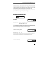
Entering Setup
To enter Setup, simply take the printer off line and press the SETUP button.
The ONLINE indicator will begin to flash yellow and the display will
temporarily show the following.
Entering
Setup Menus
After the above message has been shown, the display will change to the
first menu available, which is the FORMS MENU as shown below. In this
case the display will also show the first submenu which will be the form
that was selected when Setup was pressed.
FORMS MENU
Form 0
Using the MENU Button
At this time you may select a different menu by pressing the MENU button
(closest to where FORMS MENU is displayed). Other menus available are the
INTERFACE MENU, the OPTIONS MENU, and the TEST MENU. This button
will also display an option for exiting Setup. If you do not wish to exit
Setup at this time, press the button indicated for No and continue to press
the MENU button to select the desired menu. The MENU button may be
pressed at any time to select a different menu.
Using the SUBMENU Button
The SUBMENU button selects additional menus that are related to the
selected menu. For instance, if the FORMS MENU has been selected, the
40
P R I N T E R
C O N F I G U R A T I O N
SUBMENU button (closest to where the form number is displayed) will
select which form (Form 0 through Form 9) is to be set up. Note that not
all menus have submenus. If no submenu is available, the bottom line will
be blank and the SUBMENU button will not be used.
Using the ITEM and VALUE Buttons
Once the correct menu and submenu (if available) is selected, pressing
either of the ITEM buttons will cause the various items and their current
values to be displayed. Note that the items and their values are right
justified and are thus controlled by the buttons to the right of the display.
To scroll through the items available, use the ITEM buttons. To change the
value of the displayed item, use the VALUE buttons to step through the
possible choices. Remember to leave the correct value displayed before
selecting a different item or menu, since “what you see is what you get”
when Setup Mode is exited.
Exiting Setup
Two methods of exiting Setup are available. If you wish to exit Setup and
remain off line, press the MENU button to display the following option.
←No
←Yes
Exit Setup
Menus?
Pressing the button indicated for No will allow you to make additional
menu choices. Pressing the button indicated for Yes will display one of the
following messages depending on whether or not changes were made, reset
the printer if changes were made, and then leave the printer off line.
Exiting Menus
Saving Changes
Exiting Menus
No Changes
41
P R I N T E R
C O N F I G U R A T I O N
To exit Setup Mode and automatically go on line, press ONLINE. The
display will now show one of the above messages, if changes were made,
and automatically go on line.
FORMS MENU
Most form printing applications use several different forms such as packing
lists, bills of lading, invoices, checks, and green bar paper for reports. Not
all of these forms require the same printer settings for things such as font,
character size, line spacing, or form length. The FormsMaster 8000 series
printers store up to ten complete sets of form parameters including the name
of the form. These ten sets of parameters, or “forms”, are permanently
stored in the printer’s memory and are referred to as “Form 0” through
“Form 9”. These forms can be accessed from a single button on the
printer’s control panel or by a command sent from the host computer.
To access the FORMS MENU, enter Setup by pressing the SETUP button.
After the “Entering Setup Menus” message has been displayed, the
following will appear.
FORMS MENU
Form 0
Note that the actual form number will be for the form that was active prior
to entering Setup. To select a different form, press the SUBMENU button
until the desired form is displayed. Next press either of the ITEM buttons to
begin displaying the various items for that form. The items available for
each form are described on the following pages. The factory default values
are indicated with an asterisk (*) in this manual (the asterisk does not
appear on the printer’s display).
42
P R I N T E R
C O N F I G U R A T I O N
Forms Menu Items
Form Name
Form Name
FORM 0
Possible Values: Up to 16 characters of A through Z,
Space, 0 through 9
When shipped from the factory, the Form Names will be set to “FORM 0”
through “FORM 9”. This name may be changed to any combination of
capital letters (A-Z), numerals (0-9), or spaces. The name may be up to 16
characters in length.
Entering a name uses the SUBMENU and VALUE buttons. The SUBMENU
button will advance the cursor, a flashing block, which is used to indicate
the character that is to be changed. The VALUE buttons will change the
character where the cursor is currently flashing. The order of characters
that may be selected is “ABCDEFGHIJKLMNOPQRSTUVWXYZ, Space,
0123456789”. Even though the name will be right justified while being
entered, it will be automatically centered on the display when not in Setup
Mode, so there is no need to try to center it with spaces.
Tractor Path
Tractor Path
Front
Possible Values: Front, Center, Rear
Center+Rear, Frnt+Cntr+Rear
This item is only available in the FormsMaster 8003 and is used to set the
tractor path to be used for the currently selected form. Typically, most
forms are only loaded in one tractor path and the value will be set to Front,
Center, or Rear.
However, a form can also be set to use multiple paths. This may be
desirable when printing long print jobs where a paper out condition needs
to be avoided. This is often true if the job is to be run overnight or at a
remote and perhaps unattended location. When a form’s tractor path is set
to Center+Rear or Frnt+Cntr+Rear, the printer will automatically
43
P R I N T E R
C O N F I G U R A T I O N
switch to the next path, or paths, and continue printing until all the specified
paths are empty
Automatic Cut
Automatic Cut
No
Possible Values: No*, Yes
This item is only available when the optional FormsCutter is installed in the
printer. When set to Yes, the printer will automatically cut each form at the
perforation (based upon the Form Length setting) and eject the form into
the paper basket that is installed with the FormsCutter. If set to No, the
paper will exit through the lower, continuous paper path into the basket on
the print stand. To manually cut a form or report at the end of the current
page, the user can take the printer offline and press the UNLOAD button. See
the FormsMaster 8000 Series FormsCutter Manual for additional
information.
Cut Adjustment
Cut Adjustment
0
Possible Values: -0.2986” … 0* … +0.2986”
This item may be used to adjust the position of the cut relative to the top-ofform for improved cut accuracy. This item is only available when the
optional FormsCutter is installed. Refer to the FormsCutter manual for
more information.
Lines Per Inch
Possible Values: 6*, 8
This item sets the line pitch to 6 or 8 Lines Per Inch (LPI).
44
Lines/Inch
6
P R I N T E R
Form Length
C O N F I G U R A T I O N
Form Length
66 Lines
Possible Values: 1 … 66* … 227 Lines
This item sets the form length in lines at the current line pitch (LPI). For
example: for an eleven inch form, enter 66 if you are using six lines per
inch or 88 if you are using eight lines per inch.
Top Margin
Top Margin
0 Lines
Possible Values: 0* … 226 Lines
This item sets the top margin in lines. Setting a top margin will reduce the
size of the printable area of the page by the number of lines set. Printing
will not be allowed above the top margin.
Note: In most cases changing where printing begins on a form should be
accomplished with ALIGN PRINT rather than with a top margin.
Adding a top margin may cause some programs to print the first form
correctly and then print following forms too far down the page if the
program sending the data does not require the margin.
Bottom Margin
Bottom Margin
0 Lines
Possible Values: 0* … 226 Lines
This item sets the bottom margin in lines. Setting a bottom margin will
reduce the size of the printable area of the page by the number of lines set.
When the bottom margin is reached, the remainder of the page will be
skipped and printing will resume at the beginning of the next page (or top
margin if one is set). Adding a bottom margin may cause some data to be
printed on the wrong page if the program sending the data does not require
the margin.
45
P R I N T E R
C O N F I G U R A T I O N
Characters Per Inch
Characters/Inch
10
Possible Values: 10*, 12, 13.3, 15, 16.74, 17.14, 20
This item sets the default character pitch in Characters Per Inch (CPI).
(Note that OCR-A and OCR-B characters are only valid at 10 CPI will
always print at 10 CPI regardless of this setting.)
Left Margin
Left Margin
Column 0
Possible Values: Column 0* … 268
This item sets the left margin in columns (characters) relative to the left
edge of the paper. The column width is based upon the current character
pitch (CPI). The left margin must be less than the right margin. The left
margin may be used to cause printing to begin farther to the right on a form.
In many cases using ALIGN PRINT may be preferable to using a left margin
(see Aligning Print on page 34) .
Right Margin
Right Margin
Column 272
Possible Values: Column 4 … 272*
This item sets the right margin in columns (characters) relative to the left
edge of the paper. A value of 272 is large enough to insure that characters
can be printed to the right end of the paper regardless of character pitch
(CPI). The right margin must be greater than the left margin. Text
characters that would have printed to the right of the margin will be
“wrapped around” and printed at the beginning of the next line. Graphic
data that would have printed to the right of the margin will be truncated (not
wrapped around). However, any data which would print before the right
margin but beyond the edge of the paper (either in the sprocket holes or on
the platen) will be truncated.
46
P R I N T E R
C O N F I G U R A T I O N
Font
Font
Epson FX FD
Possible Values: Epson FX FD, DF*, LQ;
PC English FD, DF, LQ;
PC Latin 2 FD, DF, LQ;
DEC LA120 FD, DF, LQ;
EBCDIC FD, DF, LQ;
OCR-A OQ;
OCR-B OQ;
Roman 8 FD, DF, LQ;
ML Euro (858) FD, DF, LQ;
ML (850) FD, DF, LQ
This item selects the default font (character set, quality) to be used.
Draft Speed
Draft Speed
Normal
Possible Values: Normal*, Fast
This item selects whether the Draft Font (DF) or the Fast Draft (FD) font
will be selected when the printer receives a “select draft font” command
from the host computer. This will allow the Fast Draft font to be used with
programs which would not be able to otherwise.
Impact Force
Impact Force
Normal
Possible Values: Normal*, High
This item may be used to select High Impact for improved printing on
multipart forms that do not otherwise print well on the back copies.
Language
Language
USA
Possible Values: USA*, France, Germany, England,
Denmark, Sweden, Italy, Spain, Japan,
Finland
47
P R I N T E R
C O N F I G U R A T I O N
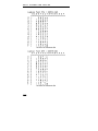
This item selects the character substitution table to be used for an alternate
language when printing. The Epson font must be selected in order for this
feature to work properly. The character substitutions are shown in the
following table.
Char Value
USA
France
Germany
England
Denmark
Sweden
Italy
Spain
Japan
35
#
#
#
£
#
#
#
PTS
#
36
$
$
$
$
$
¤
$
$
$
64
@
à
§
@
@
É
@
@
@
91
[
°
Ä
[
Æ
Ä
°
¡
[
92
\
ç
Ö
\
Ø
Ö
\
Ñ
¥
93 94 96 123 124 125 126
] ^ `
{
¦
}
˜
§ ^ `
é
ù
è
¨
Ü ^ `
ä
ö
ü
ß
] ^ `
{
¦
}
˜
Å ^ `
æ
ø
å
˜
Å Ü é
ä
ö
å
ü
é ^ ù
à
ò
è
ì
¿ ^ `
¨
ñ
}
˜
] ^ `
{
¦
}
˜
Zero Style
Zero
Normal
Possible Values: Normal*, Slashed
This item selects whether the numeral zero is printed with or without a slash
through it. (This is true for normal text characters. The optional Imager
and ImagerPlus Coprocessors have a separate setup item for zero characters
they generate.)
Unidirectional Printing
Unidirectional
No
Possible Values: No*, Yes
This item selects unidirectional printing instead of bidirectional printing.
This may be used to improve the straightness of vertical lines for critical
applications such as printing small bar codes.
48
P R I N T E R
C O N F I G U R A T I O N
INTERFACE MENU
The Interface Menu may contain several submenus. These submenus are
for setting up items pertaining to the hardware interfaces such as the serial
and parallel ports as well as the optional character processing interfaces
such as the Imager and ImagerPlus.
In addition to the standard parallel interface and the RS-232C serial
interface which are furnished with the printer, one more hardware interface
such as Coax/Twinax, IPDS Coax, IPDS Twinax, or 10BaseT LAN may
also be installed, as well as an Imager or ImagerPlus graphic option. The
Setup items for each interface are described in one of the following
sections.
The printer will automatically receive data from any of the hardware
interfaces, or ports, as described below in “Automatic Port Switching”.
RS-232C Serial Interface on page 51
Parallel Interface on page 55
Etherlink 10BaseT Interface on page 57
Coax Interface on page 59
Twinax Interface on page 63
IPDS Coax Interface on page 66
IPDS Twinax Interface on page 71
Imager and ImagerPlus Interface on page 72
Automatic Port Switching
The FormsMaster 8000 series printers will automatically accept data from
the Parallel Interface, the RS-232 Serial Interface, and any optionally
installed hardware interface. This feature is always active and does not
require user intervention to change ports.
In most installations, the printer is only connected to one computer and this
feature may be ignored. If this is true of your installation, you may skip this
section and proceed with one of the following sections which applies to the
interface port you will be using.
49
P R I N T E R
C O N F I G U R A T I O N
In other installations the printer may be attached to two or three computers.
This section describes how the printer will automatically switch control of
the printer from one hardware interface port to another.
Note that since any one of these ports can become active at any time, items
which pertain to each port need to be set up as described in the following
sections. Ports that will not be used (not installed or not connected to a
computer) do not need to be set up.
When the first data are received at any port after turning on power to the
printer, that port becomes the “active” port. While one of the ports is
active, each of the other ports will accept only a limited number of
characters before reflecting a “busy” condition to the computer attached to
those ports.
To change which port is active, the printer’s buffer must be empty for at
least 15 seconds and data must be received from a different port.
Therefore, if data are never received from more than one port, that port is
always the active port.
When the active port changes, the printer will automatically perform a
Carriage Return (CR) and reselect the emulation that was in effect for that
port. The printer will also perform a Form Feed (FF) if not already at the
top of form.
Entering the Interface Menu
To Enter the Interface Menu, enter Setup and press the MENU button until
INTERFACE MENU is displayed on the top line as shown below.
INTERFACE MENU
Serial
The SUBMENU options for the INTERFACE MENU always include the Serial
and Parallel ports. The other ports mentioned earlier will only be displayed
if they are installed in the printer. This is also true of the Imager or
ImagerPlus graphics options. To select the desired interface, press the
SUBMENU button until that interface is displayed on the bottom line. Next
press either of the ITEM buttons to begin displaying the items associated
50
P R I N T E R
C O N F I G U R A T I O N
with that interface. Each interface and the items which pertain to that
interface are listed on the following pages. Note that many items are the
same for more than one interface since the computer attached to that
interface may have different requirements for each of those items.
The factory default values are indicated with an asterisk (*) in this manual
(the asterisk does not appear on the printer’s display).
RS-232C Serial Interface Items
INTERFACE MENU
Serial
Emulation
Emulation
Epson
Possible Values: Epson*, IBM Proprinter,
DEC LA120, TTY,
Printek, ANSI X3.64
This item selects the emulation to be used whenever the serial port is active
(see “Automatic Port Switching” earlier in this section). Emulation should
be set to match the type of printer your software supports.
Automatic Carriage Return
Auto CR
On
Possible Values: Off, On*
This item enables or disables automatic Carriage Returns (CR) whenever a
Line Feed (LF), Vertical Tab (VT), or Form Feed (FF) is received.
Automatic Line Feed
Auto LF
Off
51
P R I N T E R
C O N F I G U R A T I O N
Possible Values: Off*, On
This item enables or disables automatic Line Feeds (LF) when a Carriage
Return (CR) is received.
Perform Host Form Feed at Top-of-Form
Host FF at TOF
No
Possible Values: No*, Yes
This item selects whether Form Feeds (FF) will be performed when
received from the host computer if the paper is already positioned at the top
of form (TOF). Setting this item to No will help prevent blank pages.
Characters
Characters
Control
Possible Values: Control*, Printable
This item selects whether certain control character symbols will be printed
or be treated as control characters. The effect of this is dependent upon the
Emulation selected.
Minimum Buffer
Minimum Buffer
No
Possible Values: No*, Yes
This item selects whether the smallest possible I/O buffer should be used.
Setting this item to No will allow the printer to make maximum use of the
I/O buffer (see “Paper Out Fault” on page 79 for more information on
buffer size). Setting this to Yes may decrease performance, but is useful
when using the printer with operating systems that try to keep track of
which page is currently being printed by the printer. This may also be
useful when using serial I/O with systems that do not respond quickly
enough to handshake signals.
Baud Rate
52
Baud Rate
P R I N T E R
C O N F I G U R A T I O N
9600
Possible Values: 110, 150, 300, 600, 1200, 2400, 4800,
9600*, 19200, 38400
This item selects the baud rate for the serial interface. This must be set to
match the baud rate setting on the host computer.
Data Bits
Data Bits
8
Possible Values: 8*, 7
This item selects the number of data bits in the serial character frame. This
must be set to match the character size setting on the host computer.
Stop Bits
Stop Bits
1
Possible Values: 1*, 2
This item sets the number of stop bits to be used at the end of the serial
character frame. This must be set to match the stop bit setting on the host
computer.
Parity
Parity
None
Possible Values: None*, Even, Odd
This item Selects the parity checking requirements for the serial data bits.
This must be set to match the parity setting on the host computer.
Busy Signal Polarity
Busy Polarity
Low
Possible Values: Low*, High
53
P R I N T E R
C O N F I G U R A T I O N
This item selects the polarity of the busy signal (pin 11 of the RS-232C
interface). Busy is set whenever the printer is offline, the serial input buffer
is full, or another interface port is currently active (see “Automatic Port
Switching” earlier in this section).
Data Terminal Ready
DTR
Power On/Off
Possible Values: Power On/Off*
Online/Offline
Busy/Not Busy
Selects the condition to be reflected by the DTR signal (pin 20 of the RS232C interface). In most cases, especially those involving a MODEM, this
Selecting
signal should be set to indicate Power On/Off.
Online/Offline will reflect only the condition indicated and does not
reflect a buffer full condition. Busy/Not Busy will cause DTR to indicate
both the online/offline status and buffer full condition (see “Busy Polarity”
above).
RTS/CTS Handshaking
RTS/CTS
Off
Possible Values: Off*, On
Enables or disables RTS/CTS hardware handshaking. If enabled, RTS
takes on the alternate meaning of “ready to receive”. The printer will assert
RTS when it is capable of receiving data. When the printer is off line, the
serial input buffer is full, or another interface port is currently active, the
printer will de-assert RTS. Likewise, the host computer will assert CTS
when it is capable of receiving data.
XON/XOFF Handshaking
Possible Values: Off*, On
54
XON/XOFF
Off
P R I N T E R
C O N F I G U R A T I O N
Enables or disables the transmission of the XON and XOFF characters
from the printer to the host to control data flow to the printer. XOFF will be
sent whenever the printer goes offline or the serial buffer is full. XON will
be sent when is again ready to receive characters.
ETX/ACK Handshaking
ETX/ACK
Off
Possible Values: Off*, On
Enables or disables the ACK response to receipt of the ETX character. This
handshake method is useful for conditions where there are long
transmission line delays such as telephone lines which may be routed
through satellites. An ACK character will be returned to the host computer
after an ETX character is received and processed. ETX characters used for
handshaking cannot be part of an escape sequence.
Parallel Interface Items
INTERFACE MENU
Parallel
Emulation
Emulation
Epson
Possible Values: Epson*, IBM Proprinter,
DEC LA120, TTY,
Printek, ANSI X3.64
This item selects the emulation to be used whenever the parallel port is
active (see “Automatic Port Switching” earlier in this section). The
emulation should be set to match the type of printer your software supports.
Automatic Carriage Return
Auto CR
On
Possible Values: Off, On*
55
P R I N T E R
C O N F I G U R A T I O N
This item enables or disables automatic Carriage Returns (CR) whenever a
Line Feed (LF), Vertical Tab (VT), or Form Feed (FF) is received.
Automatic Line Feed
Auto LF
Off
Possible Values: Off*, On
This item enables or disables automatic Line Feeds (LF) when a Carriage
Return (CR) is received.
Perform Host Form Feed at Top-of-Form
Host FF at TOF
No
Possible Values: No*, Yes
This item selects whether Form Feeds (FF) will be performed when
received from the host computer if the paper is already positioned at the top
of form (TOF). Setting this item to No will help prevent blank pages.
Characters
Characters
Control
Possible Values: Control*, Printable
This item selects whether certain control character symbols will be printed
or be treated as control characters. The effect of this is dependent upon the
emulation selected above.
Minimum Buffer
Possible Values: No*, Yes
56
Minimum Buffer
No
P R I N T E R
C O N F I G U R A T I O N
This item selects whether the minimum I/O buffer size should be used.
Setting this item to No will allow the printer to make maximum use of the
I/O buffer (see “Paper Out Fault” on page 79 for more information on
buffer size). Setting this to Yes may decrease performance, but is useful
when using the printer with operating systems that try to keep track of
which page is currently being printed by the printer.
EtherLink LAN Interface Items
INTERFACE MENU
LAN
Emulation
Emulation
Epson
Possible Values: Epson*, Basic Bar Codes, IBM
Proprinter, DEC LA120, TTY,
Printek, ANSI X3.64
This item selects the emulation to be used whenever the LAN port is active
(see “Automatic Port Switching” earlier in this section). The emulation
should be set to match the type of printer your software supports.
Automatic Carriage Return
Auto CR
On
Possible Values: Off, On*
This item enables or disables automatic Carriage Returns (CR) whenever a
Line Feed (LF), Vertical Tab (VT), or Form Feed (FF) is received.
Automatic Line Feed
Auto LF
Off
Possible Values: Off*, On
57
P R I N T E R
C O N F I G U R A T I O N
This item enables or disables automatic Line Feeds (LF) when a Carriage
Return (CR) is received.
Perform Host Form Feed at Top-of-Form
Host FF at TOF
No
Possible Values: No*, Yes
This item selects whether Form Feeds (FF) will be performed when
received from the host computer if the paper is already positioned at the top
of form (TOF). Setting this item to No will help prevent blank pages.
Characters
Characters
Control
Possible Values: Control*, Printable
This item selects whether certain control character symbols will be printed
or be treated as control characters. The effect of this is dependent upon the
emulation selected above.
Minimum Buffer
Minimum Buffer
No
Possible Values: No*, Yes
This item selects whether the minimum I/O buffer size should be used.
Setting this item to No will allow the printer to make maximum use of the
I/O buffer (see “Paper Out Fault” on page 79 for more information on
buffer size). Setting this to Yes may decrease performance, but is useful
when using the printer with operating systems that try to keep track of
which page is currently being printed by the printer.
58
P R I N T E R
C O N F I G U R A T I O N
Coax/Twinax Interface Items
When Configured for Coax Operation
INTERFACE MENU
Coax
When the optional Coax/Twinax Interface is installed, the printer will
automatically determine which of these two interfaces are being used by
sensing which adapter cable is attached to the printer at power on. If the
Coax adapter is attached, the following Setup items will be displayed. If
you are using the printer in a Twinax Configuration, refer to the next
section of this chapter.
Printer Emulation
PrinterEmulation
3287
Possible Values: 3287*, 3262
This item selects the IBM printer model to be emulated.
Maximum Print Position
Max Print Pos
132
Possible Values: 132*, None
This item selects whether the maximum print position is column 132 or if
no maximum position is enforced.
Maximum Print Line
Max Print Line
66
Possible Values: 66*, None
This item selects whether the maximum print line is line 66 or if no
maximum position is enforced.
59
P R I N T E R
C O N F I G U R A T I O N
Form Feed After Local Copy
FF on Local Copy
Enable
Possible Values: Enable*, Disable
This item selects whether a form feed will automatically be performed after
a local copy operation.
Form Feed Validity (LU-3)
FF Valid (LU-3)
Anywhere
Possible Values: Anywhere*, Col 1 or MPP+1
This item selects whether a Form Feed character will cause a form feed to
occur when received anywhere in the data stream or only when received at
column 1 or at MPP+1.
Form Feed At EOM (LU-3)
FF at EOM (LU-3)
Disable
Possible Values: Enable, Disable*
This item selects whether a form feed will automatically be performed after
an End Of Message is received.
Paper Error Reporting
Paper Err Report
Disable
Possible Values: Enable, Disable*
This item selects whether paper errors will be reported to the host.
60
P R I N T E R
C O N F I G U R A T I O N
Default Character Set
Possible Values: Multinational*
USA
Austria/Germany
Belgium
Brazil
Canadian French
Denmark/Norway
Finland/Sweden
Character Set
Multinational
France
Italy
Japan (English)
Japan (Katakana)
Portuguese
Spain
Spanish Speaking
United Kingdom
This item selects the default character translation.
Logical Not Character
Logical Not Char
5E Hex
Possible Values: 5E Hex (caret ^), E1 Hex (not symbol ¬)
This item selects which character is actually printed when a logical not
character is received (Shift-6 on most keyboards).
Null Suppression (LU-3)
NUL Supp (LU-3)
Disable (NUL=SP)
Possible Values: Disable (NUL=SP)*, Enable
This item selects whether NUL characters will suppressed or converted to
spaces.
Host Character Pitch Control
Host CPI Control
Enable
Possible Values: Enable*, Disable
This item selects whether the host is able to control the character pitch
(Characters Per Inch) or if it is controlled only by the printer Setup menus.
Host Line Pitch Control
Host LPI Control
61
P R I N T E R
C O N F I G U R A T I O N
Enable
Possible Values: Enable*, Disable
This item selects whether the host is able to control the line pitch (Lines Per
Inch) or if it is controlled only by the printer Setup menus.
Host Form Length Control
Host Form Length
Enable
Possible Values: Enable*, Disable
This item selects whether the host is able to control the form length or if it is
controlled only by the printer Setup menus.
Buffer Size
Buffer Size
4K
Possible Values: 4K*, 2K
This item selects the input buffer size.
Display Screen Size
Display Size
1920
Possible Values: 1920*, 2560, 3440, 3564, 920
This item selects the display screen size.
Test Mode
Test Mode
Off
Possible Values: Off*, EBCDIC Code Dump, Loopback
This item selects the test mode within the CX/TX interface. When set to
Off, the printer will operate normally. When set to EBCDIC Code Dump,
the printer will print the EBCDIC value of the characters received to assist
programmers in software debugging (for more information refer to the
62
P R I N T E R
C O N F I G U R A T I O N
FormsMaster 8000 Series Programmer’s Manual).
When set to
Loopback, the interface will perform internal diagnostics and print the
result.
Reserved Parameter
(new)Parameter19
(unused)0
Possible Values: (unused)0*, 1 - 255
This item is reserved for future use.
Coax/Twinax Interface Items
When Configured for Twinax Operation
INTERFACE MENU
Twinax
When the optional Coax/Twinax Interface is installed, the printer will
automatically determine which of these two interfaces are being used by
sensing which adapter cable is attached to the printer at power on. If the
Twinax Smart-T adapter is attached, the following Setup items will be
displayed. If you are using the printer in a Coax Configuration, refer to the
previous section of this chapter.
Note: The Twinax Address is selected by using the rotary switch on the
back of the printer next to the 15 pin “D” connector where the twinax
Smart-T adapter is connected.
Printer Emulation
PrinterEmulation
4214
63
P R I N T E R
C O N F I G U R A T I O N
Possible Values: 4214*, 5225, 5256, 4234
This item selects the IBM printer model to be emulated.
Default Character Set
Possible Values: Multinational*
USA
Austria/Germany
Belgium
Brazil
Canadian French
Denmark/Norway
Finland/Sweden
Character Set
Multinational
France
Italy
Japan (English)
Japan (Katakana)
Portuguese
Spain
Spanish Speaking
United Kingdom
This item selects the default character translation.
Logical Not Character
Logical Not Char
5E Hex
Possible Values: 5E Hex (caret ^), E1 Hex (not symbol ¬)
This item selects which character is actually printed when a logical not
character is received (Shift-6 on most keyboards).
Host Print Quality Control
Host Print Qual
Enable
Possible Values: Enable*, Disable
This item selects whether the host is able to control the print quality (draft
or letter quality) or if it is controlled only by the printer Setup menus.
Host Character Pitch Control
64
Host CPI Control
Enable
P R I N T E R
C O N F I G U R A T I O N
Possible Values: Enable*, Disable
This item selects whether the host is able to control the character pitch
(Characters Per Inch) or if it is controlled only by the printer Setup menus.
Host Line Pitch Control
Host LPI Control
Enable
Possible Values: Enable*, Disable
This item selects whether the host is able to control the line pitch (Lines Per
Inch) or if it is controlled only by the printer Setup menus.
Host Form Length Control
Host Form Length
Enable
Possible Values: Enable*, Disable
This item selects whether the host is able to control the form length or if it is
controlled only by the printer Setup menus.
Host Bin Select
Host Bin Select
Enable
Possible Values: Enable*, Disable
This item selects whether the host is able to change bin (form) selections or
if it is controlled only by the printer control panel.
Test Mode
Test Mode
Off
Possible Values: Off*, EBCDIC Code Dump, Loopback
65
P R I N T E R
C O N F I G U R A T I O N
This item selects the test mode within the CX/TX interface. When set to
Off, the printer will operate normally. When set to EBCDIC Code Dump,
the printer will print the EBCDIC value of the characters received to assist
programmers in software debugging (for more information refer to the
FormsMaster 8000 Series Programmer’s Manual).
When set to
Loopback, the interface will perform internal diagnostics and print the
result.
Reserved Parameter
(new)Parameter19
(unused)0
Possible Values: (unused)0*, 1 - 255
This item is reserved for future use.
IPDS Coax Interface Items
INTERFACE MENU
IPDS Coax
Maximum Print Position
Max Print Pos
132
Possible Values: 132*, None
This item selects whether the maximum print position is column 132 or if
no maximum position is enforced.
Carriage Return Received at MPP+1
Possible Values: CR*, NL
66
CR at MPP+1
CR
P R I N T E R
C O N F I G U R A T I O N
This item selects whether a Carriage Return received at MPP+1 will cause
only a Carriage Return or a New Line (Carriage Return and Line Feed) to
be performed.
New Line Received at MPP+1
NL at MPP+1
NL
Possible Values: NL*, 2 x NL
This item selects whether a New Line received at MPP+1 will cause one or
two New Lines to be performed.
Maximum Print Line
Max Print Line
66
Possible Values: 66*, None
This item selects whether the maximum print line is line 66 or if no
maximum position is enforced.
Form Feed After Local Copy
FF on Local Copy
Enable
Possible Values: Enable*, Disable
This item selects whether a form feed will automatically be performed after
a local copy operation.
Form Feed Validity (LU-3)
FF Valid (LU-3)
Anywhere
Possible Values: Anywhere*, Col 1 or MPP+1
67
P R I N T E R
C O N F I G U R A T I O N
This item selects whether a Form Feed character will cause a form feed to
occur when received anywhere in the data stream or only when received at
column 1 or at MPP+1.
Form Feed At EOM (LU-3)
FF at EOM (LU-3)
Enable
Possible Values: Enable, Disable*
This item selects whether a form feed will automatically be performed after
an End Of Message is received.
Form Feed Operation
FF Operation
FF
Possible Values: FF, FF + Space*
This item selects whether only a Form Feed or a Form Feed and a Space
will be performed when a Form Feed character is received.
Paper Error Reporting
Paper Err Report
Disable
Possible Values: Enable, Disable*
This item selects whether paper errors will be reported to the host.
Default Character Set
Possible Values: Multinational*
USA
Austria/Germany
68
Character Set
Multinational
France
Italy
Japan (English)
P R I N T E R
Belgium
Brazil
Canadian French
Denmark/Norway
Finland/Sweden
C O N F I G U R A T I O N
Japan (Katakana)
Portuguese
Spain
Spanish Speaking
United Kingdom
This item selects the default character translation.
Logical Not Character
Logical Not Char
5E Hex
Possible Values: 5E Hex (caret ^), E1 Hex (not symbol ¬)
This item selects which character is actually printed when a logical not
character is received (Shift-6 on most keyboards).
Null Suppression (LU-3)
NUL Supp (LU-3)
Disable (NUL=SP)
Possible Values: Disable (NUL=SP)*, Enable
This item selects whether NUL characters will suppressed or converted to
spaces.
Host Impact Control
Host Impact Ctrl
Enable
Possible Values: Enable*, Disable
This item selects whether the host is able to control the normal or high
impact setting or if it is controlled only by the printer Setup menus.
Host Bin Select
Host Bin Select
Enable
Possible Values: Enable*, Disable
This item selects whether the host is able to change bin (form) selections or
if it is controlled only by the printer control panel.
69
P R I N T E R
C O N F I G U R A T I O N
Buffer Size
Buffer Size
4K
Possible Values: 4K*, 2K
This item selects the input buffer size.
Display Screen Size
Display Size
1920
Possible Values: 1920*, 2560, 3440, 3564, 920
This item selects the display screen size.
Test Mode
Test Mode
Off
Possible Values: Off*, EBCDIC Code Dump, Loopback
This item selects the test mode within the CX/TX interface. When set to
Off, the printer will operate normally. When set to EBCDIC Code Dump,
the printer will print the EBCDIC value of the characters received to assist
programmers in software debugging (for more information refer to the
FormsMaster 8000 Series Programmer’s Manual).
When set to
Loopback, the interface will perform internal diagnostics and print the
result.
Reserved Parameter
Possible Values: (unused)0*, 1 - 255
This item is reserved for future use.
70
(new)Parameter17
(unused)0
P R I N T E R
C O N F I G U R A T I O N
IPDS Twinax Interface Items
Note: The Twinax Address is selected by using the rotary switch on the
back of the printer next to the 15 pin “D” connector where the twinax
Smart-T adapter is connected.
INTERFACE MENU
IPDS Twinax
Default Character Set
Possible Values: Multinational*
USA
Austria/Germany
Belgium
Brazil
Canadian French
Denmark/Norway
Finland/Sweden
Character Set
Multinational
France
Italy
Japan (English)
Japan (Katakana)
Portuguese
Spain
Spanish Speaking
United Kingdom
This item selects the default character translation.
Host Impact Control
Host Impact Ctrl
Enable
Possible Values: Enable*, Disable
This item selects whether the host is able to control the normal or high
impact setting or if it is controlled only by the printer Setup menus.
71
P R I N T E R
C O N F I G U R A T I O N
Host Bin Select
Host Bin Select
Enable
Possible Values: Enable*, Disable
This item selects whether the host is able to change bin (form) selections or
if it is controlled only by the printer control panel.
Test Mode
Test Mode
Off
Possible Values: Off*, EBCDIC Code Dump, Loopback
This item selects the test mode within the CX/TX interface. When set to
Off, the printer will operate normally. When set to EBCDIC Code Dump,
the printer will print the EBCDIC value of the characters received to assist
programmers in software debugging (for more information refer to the
FormsMaster 8000 Series Programmer’s Manual).
When set to
Loopback, the interface will perform internal diagnostics and print the
result.
Reserved Parameter
(new)Parameter4
(unused)0
Possible Values: (unused)0*, 1 - 255
This item is reserved for future use.
Imager and ImagerPlus Interface Items
INTERFACE MENU
Imager
72
P R I N T E R
C O N F I G U R A T I O N
or
INTERFACE MENU
ImagerPlus
The printer will automatically display Imager or ImagerPlus as shown
above based upon which interface is installed. The descriptions in this
manual are brief. For more information, please refer to the appropriate
Imager or ImagerPlus manual.
Emulation
Emulation
QMS CodeV v2
Possible Values: QMS CodeV v2*, PTX CodeV v2,
Printronix IGP
This item sets the Imager or ImagerPlus emulation mode. QMS CodeV v2
selects QMS Code V version 2, PTX CodeV v2 selects Printronix Code V
version 2. Note that Printronix IGP is only available in the
ImagerPlus.
Control Character
ControlCharacter
^ (5E Hex)
Possible Values: ^ (5E Hex)*
SOH (01 Hex) through HT (09 Hex),
SO (0E Hex) through (FF Hex)
This item sets the control character used to begin commands. The character
normally used for QMS is the caret (^) and the character nomally used for
IGP is the tilde (~) (if you change the emulation to Printronix IGP, you
may need to change the control characcter to the tilde).
Line Terminator
Line Terminator
LF
Possible Values: LF*, CR
This item sets the line terminating character to a Line Feed or a Carriage
Return.
73
P R I N T E R
C O N F I G U R A T I O N
Bar Code Density
Bar Code Density
High-Res
Possible Values: Low-Res, Medium-Res, High-Res*,
Graphics Med-Res
This item sets the density, or graphics resolution, for bar codes.
QMS Character Set
(QMS CodeV v2 and PTX CodeV v2 only)
Possible Values: USA
United Kingdom
Sweden/Finland
Norway/Denmark
Japan
Germany
QMS Char Set
USA
France
Italy
Spain
PC Subset
CodeV Version1
This item selects the character set.
^PY Translation Mode
(QMS CodeV v2 and PTX CodeV v2 only)
^PY Translation
Not Active
Possible Values: Not Active*, Active
This item selects whether or not Filter Mode is active at power on or reset.
^F Free Format Mode
(QMS CodeV v2 and PTX CodeV v2 only)
^F Free Format
Not Active
Possible Values: Not Active*, Active
This item selects whether or not the Free Format Mode is active in Filter
Mode.
74
P R I N T E R
C O N F I G U R A T I O N
^ X Ignore Data Mode
(QMS CodeV v2 and PTX CodeV v2 only)
^X Ignore Data
Not Active
Possible Values: Not Active*, Active
This item selects whether data will be ignored until a ^A is received.
Imager/ImagerPlus Zero Style
(QMS CodeV v2 and PTX CodeV v2 only)
Imager Zero
Slashed
Possible Values: Slashed*, Normal
This item selects the type of zero character (Ø or O) to be printed by the
Imager or ImagerPlus.
Line Registration
(QMS CodeV v2 and PTX CodeV v2 only)
LineRegistration
Not Maintained
Possible Values: Not Maintained*, Maintained
This item selects whether or not the form will automatically be advanced to
the next line boundary when Filter Mode is exited.
Vertical DPI Resolution
(QMS CodeV v2 and PTX CodeV v2 only)
Vertical DPI
72
Possible Values: 72*, 70
This item sets the vertical resolution to 72 or 70 Dots Per Inch.
Vertical Text Spacing
(QMS CodeV v2 and PTX CodeV v2 only)
Vertical Text SP
Version 2
Possible Values: Version 2*, Version 1
This item selects whether text should be spaced vertically as in Code V
version 1 or version 2.
75
P R I N T E R
C O N F I G U R A T I O N
Code V Space Fields
(QMS CodeV v2 and PTX CodeV v2 only)
CodeV SP Fields
Process
Possible Values: Process*, Ignore
This item selects whether Code V space fields should be processed.
IGP Character Set
(Printronix IGP only)
Possible Values: ASCII
Germany
Sweden
Denmark
Norway
Finland
IGP Char Set
ASCII
English
Dutch
France
Spain
Italy
Turkey
This item selects the character set.
Delete Logos
(Printronix IGP only)
Delete Logos
No
Possible Values: No*, Yes
This item selects whether logos should be deleted when a form is deleted.
Quiet Mode
(Printronix IGP only)
Quiet Mode
Not Active
Possible Values: Not Active*, Active
This item selects whether or not the quiet mode is active at power on.
Spacing Mode
76
Spacing
P R I N T E R
C O N F I G U R A T I O N
(Printronix IGP only)
IGP 10/20/40
Possible Values: IGP 10/20/40*, IGP 30
This item selects the Spacing mode.
77
P R I N T E R
C O N F I G U R A T I O N
OPTIONS MENU
The OPTIONS MENU contains items which do not pertain only to a specific
form or specific interface, but rather affect how the printer works under all
conditions. To access the options menu, enter Setup and then press MENU
until OPTIONS MENU is displayed
OPTIONS MENU
Note that the options menu has no submenus. Therefore, press either of the
ITEM buttons to begin displaying the items available. The factory default
values are indicated with an asterisk (*) in this manual (the asterisk does not
appear on the printer’s display).
Maximum Form Allowed
Max Form Allowed
Form 2
Possible Values: Form 0 … Form 2* … Form 9
This item sets the last form number to be displayed for operator selection
with the FORM SELECT button or while in the FORMS MENU. This
allows the operator to see only the forms that are in use rather than having
to sort through several unused forms.
Note that when setting this value that you may not select a value less than
the form currently selected when Setup was entered, or less than the form
currently selected in the “Setup: FORMS” menu.
Automatic Scroll Delay
Auto-Scroll
1 Second Delay
Possible Values: Off, 1* to 15 Second Delay
This item sets the number of seconds to delay before scrolling the top of
form to the tear bar when the printer is idle (no additional data received
78
P R I N T E R
C O N F I G U R A T I O N
since the last print operation) and a form boundary (bottom of the form
according to the Form Length setting for the current form) has been
reached. If printing finishes and the form boundary has not been reached,
take the printer off line and the FORM FEED button may be used to advance
the form to the tear bar. This item may also be used to disable Auto-Scroll
by setting the value to Off. When disabled, the FORM FEED button must
always be used to advance the form to the tear bar.
Paper Out Fault Action
Paper Out Fault
Finish Page
Possible Values: Finish Page*
Reprint Page
Break Page
This item selects what action is to be taken when a paper out condition
occurs. The action taken for each of the possible values is described in the
following paragraphs.
When Finish Page is selected, the printer will attempt to print to the
bottom of the page when a normal paper out condition occurs. Conditions
that will prevent this from happening are when the end of paper is detected
too far from the end of the form (the printer assumes there is not a complete
page available), when reverse paper motion is attempted within the last one
inch of the form, or when a paper jam occurs. If the printer is unable to
finish printing the page, it will attempt to reprint the page as described
below (also refer to the Reprint Page Size option which follows). Note that
if highly precise printing is required in the last inch of the form, Finish
Page may not provide accurate enough paper motion since the form is no
longer controlled by the tractor mechanism .
When Reprint Page is selected, the printer will stop printing as soon as
the end of paper or a paper jam condition is detected and the printer will go
off line. After a new box of forms is loaded, the printer will attempt to
reprint the current page from the beginning. If the printer is able to reprint
the page, Reprinting Page! will be displayed when the new form is
loaded (the previous partially printed page should probably be discarded).
If the printer is unable to reprint the page, the page will be broken, Cannot
Reprint - Page Too Large will be displayed, and printing will resume
where it left off as described in the next paragraph. The printer’s ability to
79
P R I N T E R
C O N F I G U R A T I O N
complete the reprint successfully depends on whether the data for the
current page is still in the printer’s memory. Refer to the following Reprint
Page Size option for more information regarding how much data may be
retained.
When Break Page is selected, the printer will stop printing and go off line
as soon as a paper out or paper jam condition is detected. After a new box
of forms is loaded, printing will resume where it left off. The Break Page
setting is appropriate when you know a page is too large to reprint (exceeds
available buffer size, e.g. contains large graphic images). This will suppress
the error message Cannot Reprint before printing continues.
Reprint Page Size
Page Size
8192 Characters
Possible Values: 0, …, 8192*, …, 28672
This item selects how much of the 32K byte input buffer is set aside for
reprinting a page when Finish Page or Reprint Page has been
selected for the Paper Out Fault Action item (see above). The value
selected (0 to 28K bytes in 1K byte increments) should be set to
accommodate the largest page expected, but not unnecessarily large since
the larger this is set, the smaller the effective I/O buffer. The 8K byte
default setting should be large enough to hold most pages of text, but may
not be large enough to hold more complex or graphic filled pages. If the
page size selected is not large enough, the page will be broken as described
under Paper Out Fault Action item above.
If the Paper Out Fault Action item is set to Break Page, the Reprint Page
Size may be set to 0 to allow the largest possible I/O buffer.
Ribbon Checking
Ribbon Check
On
Possible Values: On*, Off
This item selects whether or not ribbon checking is active. This feature
works exclusively with Printek ribbons. When Ribbon Checking is On, the
printer alerts the operator if a ribbon is not installed, or if the ribbon life has
80
P R I N T E R
C O N F I G U R A T I O N
been reached (see Ribbon Life below). Ribbon Check may be turned off if
these features are not desired.
Ribbon Check may also be turned off to allow the use of non-Printek brand
ribbons. Using non-Printek ribbons may limit the warranty on the print
head, so before turning Ribbon Check off, please read “Why Use Only
Printek® Brand Ribbons” on page 8 and the warranty information on page
126. Note that turning this feature off while still using Printek brand
ribbons will not affect the extended warranty.
Ribbon Life
Ribbon Life
23 Million Chars
Possible Values: 5 … 23* … 30 Million Chars
This item sets the number of “draft equivalent” characters to be printed
before the Change Ribbon message is displayed. “Draft equivalent” is an
indication of the average density, or number of dots, in a draft font
character. Characters printed using other fonts are weighted according to
their own density. Typically, fast draft characters have fewer dots while
letter quality and optical quality fonts have more and are weighted as fewer
or more draft characters accordingly. Graphics data are weighted according
to the actual number of dots printed.
81
P R I N T E R
C O N F I G U R A T I O N
TEST MENU
The TEST MENU is used to access some testing as well as some record
keeping items. To access the test menu, enter Setup and press the MENU
button until TEST MENU is displayed as shown below.
TEST MENU
Next press either of the ITEM buttons to access the test modes available.
Print the Menus
Print the Menus
No
Possible Values: No*, Menu Tree, Current Values
This item may be used to print the entire menu tree or a list of current
values.
Menu Tree will print all possible items in the menu and the possible
values for each. This may be useful in case this manual is misplaced or the
printer is upgraded to a newer version of firmware.
Current Values will print only the items relevant to the current printer
configuration and their current values. This provides a means of record
keeping or “backup”, so that the values can be checked and restored in case
an operator inadvertently changes one.
After setting this value, press ONLINE to begin printing. After printing is
completed, the value of this item will automatically return to No. Note that
once printing begins, taking the printer off line for any reason (ONLINE
button pressed, ribbon lid or paper door opened, or a paper fault) will cause
printing to be aborted.
Test Mode
82
Test Mode
P R I N T E R
C O N F I G U R A T I O N
Off
Possible Values: Off*, Barber Pole, Hex Dump,
Remote Setup, Demos
When this item is set to Barber Pole, the printer will print a rotating
character pattern. Printing may be started and stopped with the ONLINE
button.
When set to Hex Dump, the printer will print all received data in a special
debug format which may be used by programmers to solve software
problems. For more information, refer to the Hex Dump section of the
FormsMaster 8000 series Programmer’s Manual.
When set to Remote Setup, the printer is ready to receive a configuration
setup file. See “Using Remote Setup” on page 91.
When set to Demos the printer will enter a special demonstration mode. For
more information, refer to “Using the Built In Demos” below.
Using the Built In Demos
The demonstration mode, or “Demos” is a feature used by sales people to
demonstrate the FormsMaster printer’s capabilities. Printed instructions for
the Demo mode may be requested by performing the following steps.
1. Enter the Setup Test Menu and set the Test Mode to Demos as
described above, and then press ONLINE to exit Setup.
2. After the printer has finished resetting, take the printer off line and
press either of the ITEM buttons until About the Demos is
displayed.
3. Press either of the VALUE buttons until Overview is displayed.
4. Press ONLINE to begin printing the Demo Overview.
5. Repeat step 3 and then press either of the VALUE buttons until Tips is
displayed.
6. Press ONLINE to begin printing the Demo Tips.
Review these two pages to print the desired demos. Remember that while
the printer is in Demo mode, it will not accept any data from any of the host
interface ports.
83
Form Construction and Layout Tips
FORM CONSTRUCTION
Although the FormsMaster 8000 series printers have been designed to
handle difficult forms, you may come across a form that does not feed
reliably or provide adequate print quality on all copies.
One of the main causes of paper misfeeds is a form that is “tented”.
Tenting is a tent-like bulge at the perforation when forms are unfolded from
the box. The printer allows a maximum form thickness of 0.025 inches,
which a badly tented form may exceed.
Tenting is usually caused by glue drying on the perforation after the forms
maker puts the forms into the box, or forms which are not glued at all.
Forms with solid glue lines which run vertically down the entire form are
the most susceptible. If you experience such a problem, request
“interrupted glue line” forms from your vendor. This method stops the glue
approximately three-quarters of the way down the form and then resumes
gluing at the top of the next form. The gluing should not begin too far
below the top of the form or pages of the form will be able to fan apart and
be a potential cause of jamming.
Another area where not all forms are alike is in the quality of carbon paper
used, or in the way carbonless inks are applied. If the back copies of your
form are too light, request a quick-release carbon or a higher quality
carbonless inking method.
FORM LAYOUT CONSIDERATIONS
When designing preprinted forms, the most common problem is forms that
are designed “too tight”. This means that boxes where data have to be
85
S P E C I F Y I N G
F O R M S
printed are just barely large enough for the data, and that even the slightest
misalignment will cause characters to be printed on at least one of the lines
that form the box.
While the print alignment can be adjusted on the FormsMaster 8000 series
printer to 1/100th of an inch, this is often too much to expect of the forms
manufacturer. Where the preprinted information is placed in respect to the
tractor holes on the form often varies on every other form in a single box of
forms, or from one box of forms to the next.
To help avoid this situation, create larger areas for data by allocating blank
lines in the printed data for horizontal lines, and allocating blank columns
for vertical lines. If this is not possible due to the amount of data that has to
be placed on the form, avoid using a dark color to form the preprinted lines
and boxes. Use a lighter color, preferable other than a gray, that will allow
the printed characters to still be read if misalignment occurs.
86
Maintenance and Troubleshooting
ERROR MESSAGES
This section provides a partial list of fatal errors. Fatal errors typically
cannot be recovered from without the loss of data. In each case, ERROR is
shown on the top line of the display and one of the following messages is
shown on the bottom line. Suggested solutions for each of these messages
are listed to the right of each error message in the table which follows. If
the suggested solution does not solve the problem, please refer to
“Obtaining Service” on page 88.
Note that none of these messages “flash” on the display. Messages which
are flashed on the display are discussed in the “Common Error Conditions”
section on page 36.
Other errors which are not listed here or in “Daily Operation” should be
reported to the company where you purchased your printer, or to your
nearest Authorized Service Center. If you do not know the name or number
of your nearest Authorized Service Center, see “Obtaining Service” later in
this section.
Error Message
Possible Solution
Head Stall
Check print head carriage area for
obstructions.
Bad Setup Module
Check Setup Module to make sure it is
attached securely.
Replace Setup Module.
Error Message
Possible Solution
87
M A I N T E N A N C E
I/O Overflow
A N D
T R O U B L E S H O O T I N G
Make sure handshaking parameters set in
the printer and at the host computer match
each other.
Make sure interface cables are wired
correctly.
I/O Parity Error
Make sure parity setting in the printer and
at the host computer match each other.
I/O Error
Make sure any optional interface is
installed properly.
PREVENTIVE MAINTENANCE
Very little preventive maintenance is required by your FormsMaster 8000
series printer. It is only suggested that you periodically clear out any
excessive paper dust.
Also, the various bearings used in the FormsMaster 8000 should not require
any lubrication. If you do choose to lubricate any bearings, use only a 30
Wt. non-detergent motor oil. DO NOT use any grease or any vegetable
based oils.
OBTAINING SERVICE
If your FormsMaster 8000 series printer should require service, please
contact the company where you purchased the printer. If you do not know
where the printer was purchased, please call 800-368-4636 to obtain the
name and number of your nearest Printek Authorized Service Center or to
arrange for factory service.
88
Advanced Setup Features
SECURITY MENU
The SECURITY MENU is for Information System managers who want to be
able to set up a printer and then “lock out” operator changes to the various
menus. This method of security may be set independently for the Align
Print, the Forms menu, the Interface menu, or the Options menu.
When set to Edit Allowed, the user is allowed to make changes to any
item in the menu selected. When set to View, the operator can look at the
settings, but cannot edit, or change the values. When set to Initialize,
the printer will reset all values in that menu (and associated submenus) to
the factory default values and security will be set back to Edit Allowed.
The SECURITY MENU is more difficult to enter than other menus. To be
able to access this menu, the printer must be powered on while pressing the
MENU button. After the printer has finished its power up self-tests, enter
Setup and press the MENU button until SECURITY MENU is displayed on the
top line. Next press either of the ITEM buttons to begin setting security.
Align Print
Align Print
Edit Allowed
Possible Values: Edit Allowed, View Only, Initialize
This item selects whether values set using Align Print (see Aligning Print
on page 34) can be edited or only viewed by the operator. Initialize
will reset the Align Print values for all forms to zero.
89
A D V A N C E D
Forms Menu
S E T U P
F E A T U R E S
Forms Menu
Edit Allowed
Possible Values: Edit Allowed, View Only, Initialize
This item selects whether items in the FORMS MENU can be edited or only
viewed by the operator. Initialize will reset the value of all the items
for all forms to factory default values.
Interface Menu
Interface Menu
Edit Allowed
Possible Values: Edit Allowed, View Only, Initialize
This item selects whether items in the INTERFACE MENU can be edited or
only viewed by the operator. Initialize will reset the value of all the
items for all interfaces to factory default values.
Options Menu
Options Menu
Edit Allowed
Possible Values: Edit Allowed, View Only, Initialize
This item selects whether items in the OPTIONS MENU can be edited or only
viewed by the operator. Initialize will reset the value of all the items in
the options menu to factory default values.
90
Using Remote Setup
The FormsMaster 8000 Series printers may be completely configured for
operation by using the front panel buttons to access the printer setup menus.
In addition, many of the items that can be configured via the front panel
setup menus can also be configured remotely as described in this chapter.
Remote setup commands are placed in a remote setup file on a host
computer. This file may then be sent to the printer. The remote setup file
must be a text only file with each line terminated by a Line Feed (LF)
character.
The available commands listed below are shown with a combination of
upper and lower case letters to enhance readability. However, the
commands are not case sensitive. All characters are converted to upper
case before processing (except for form names, which are contained in
double quotes). White space may also be inserted to enhance readability; it
will be stripped from the commands before processing.
Each line of the file is processed individually, and must conform to one of
four possible formats:
1. A blank line (ignored).
2. A comment line, which begins with a semicolon ";" (ignored).
3. A heading line, which is enclosed in square brackets "[]".
4. An item setup line, of the format item=value.
Each item setup line must appear under the appropriate heading line. The
first heading line in the file must be [BeginPrintekSetup]. The last
heading line in the file must be [EndPrintekSetup]. All other
heading lines and item setup lines are optional.
If any errors exist in the remote setup file, no changes will be made to the
printer configuration. When possible, the printer will indicate the line
number in the file where the first error occurred. Counting of lines begins
91
U S I N G
R E M O T E
S E T U P
with 1 at the [BeginPrintekSetup] heading line.
preceding this will not be processed, and will not be counted.
Any lines
Before sending the remote setup file to the printer, minimal setup is
required via the front panel setup menus. The I/O interface to be used for
remote setup must be configured appropriately to communicate with the
host system, and the "Test Mode" item in the "TEST MENU" must be set to
"Remote Setup".
After this is done, the printer will reset, beep the bell to alert the operator,
and display the message "Waiting For Remote Setup". The remote
setup file may now be sent to the printer.
After the printer receives the remote setup file (without error), all specified
configuration changes will be made, the "Test Mode" item will revert back
to "Off", and the printer will reset. When this reset is complete, the printer
will be ready for normal interaction with the host system.
The available heading lines, and item setup lines, are documented below.
Note that all the legal values are shown for each item, but in use only one
value may be supplied in the setup file. An example file follows these
definitions.
92
U S I N G
R E M O T E
S E T U P
Remote Setup Line Definitions
[BeginPrintekSetup]
AlignPrint=FactoryDefaults
Forms=FactoryDefaults
Interfaces=FactoryDefaults
Options=FactoryDefaults
Security=FactoryDefaults
[Form0] ... [Form9]
MovePrintLeft=0.00 ... 9.99
MovePrintRight=0.00 ... 9.99
MovePrintUp=0.00 ... 9.99
MovePrintDown=0.00 ... 9.99
FormName="UPTO16CHARACTERS"
TractorPath=Front,Center,Rear,Center+Rear,
Front+Center+Rear
AutomaticCut=No,Yes
LinesPerInch=6,8
FormLength=1 ... 227
TopMargin=0 ... 226
BottomMargin=0 ... 226
CharactersPerInch=10,12,13.3,15,16.74,17.14,20
LeftMargin=0 ... 268
RightMargin=4 ... 272
Font=Epson_FX_FD,Epson_FX_DF,Epson_FX_LQ,
PC_English_FD,PC_English_DF,PC_English_LQ,
PC_Latin2_FD,PC_Latin2_DF,PC_Latin2_LQ,
DEC_LA120_FD,DEC_LA120_DF,DEC_LA120_LQ,
EBCDIC_FD,EBCDIC_DF,EBCDIC_LQ,
OCR_A_FD,OCR_B_FD
DraftSpeed=Normal,Fast
ImpactForce=Normal,High
Language=USA,France,Germany,England,Denmark,
Sweden,Italy,Spain,Japan,Finland
Zero=Normal,Slashed
Unidirectional=No,Yes
[SerialInterface]
Emulation=ANSI_X3.64,Epson,IBM_Proprinter,
DEC_LA120,TTY,Printek
AutoCR=Off,On
93
U S I N G
R E M O T E
S E T U P
AutoLF=Off,On
HostFFatTOF=No,Yes
Characters=Control,Printable
MinimumBuffer=No,Yes
BaudRate=110,150,300,600,1200,2400,
4800,9600,19200
DataBits=8,7
StopBits=1,2
Parity=None,Even,Odd
BusyPolarity=Low,High
DTR=Power,Online,Busy
XON/XOFF=Off,On
ETX/ACK=Off,On
[ParallelInterface]
Emulation=ANSI_X3.64,Epson,IBM_Proprinter,
DEC_LA120,TTY,Printek
AutoCR=Off,On
AutoLF=Off,On
HostFFatTOF=No,Yes
Characters=Control,Printable
MinimumBuffer=No,Yes
[LanInterface]
Emulation=ANSI_X3.64,Epson,IBM_Proprinter,
DEC_LA120,TTY,Printek
AutoCR=Off,On
AutoLF=Off,On
HostFFatTOF=No,Yes
Characters=Control,Printable
MinimumBuffer=No,Yes
94
U S I N G
R E M O T E
S E T U P
[CoaxInterface]
PrinterEmulation=3287,3262
MaxPrintPosition=132,None
MaxPrintLine=66,None
FFonLocalCopy=Enable,Disable
FFValid=Anywhere,Column1orMPP+1
FFatEOM=Disable,Enable
PaperErrorReport=Disable,Enable
CharacterSet=Multinational,USA,Austria/Germany,
Belgium,Brazil,CanadianFrench,
Denmark/Norway,Finland/Sweden,France,
Italy,Japan(English),Japan(Katakana),
Portuguese,Spain,SpanishSpeaking,
UnitedKingdom
LogicalNotCharacter=5Eh,E1h
NULSuppression=Disable,Enable
HostCPIControl=Enable,Disable
HostLPIControl=Enable,Disable
HostFormLength=Enable,Disable
BufferSize=4K,2K
DisplaySize=1920,2560,3440,3564,920
[TwinaxInterface]
PrinterEmulation=4214,5225,5256,4234
CharacterSet=Multinational,USA,Austria/Germany,
Belgium,Brazil,CanadianFrench,
Denmark/Norway,Finland/Sweden,France,Italy,
Japan(English),Japan(Katakana),Portuguese,
Spain,SpanishSpeaking,UnitedKingdom
LogicalNotCharacter=5Eh,E1h
HostPrintQuality=Enable,Disable
HostCPIControl=Enable,Disable
HostLPIControl=Enable,Disable
HostFormLength=Enable,Disable
HostBinSelect=Enable,Disable
95
U S I N G
R E M O T E
S E T U P
[IPDS-CoaxInterface]
MaxPrintPosition=132,None
CRatMPP+1=CR,NL
NLatMPP+1=NL,2xNL
MaxPrintLine=66,None
FFonLocalCopy=Enable,Disable
FFValid=Anywhere,Column1orMPP+1
FFatEOM=Disable,Enable
FFOperation=FF,FF+Space
PaperErrorReport=Disable,Enable
CharacterSet=Multinational,USA,Austria/Germany,
Belgium,Brazil,CanadianFrench,
Denmark/Norway,Finland/Sweden,France,Italy,
Japan(English),Japan(Katakana),Portuguese,
Spain,SpanishSpeaking,UnitedKingdom
LogicalNotCharacter=5Eh,E1h
NULSuppression=Disable,Enable
HostImpactControl=Enable,Disable
HostBinSelect=Enable,Disable
BufferSize=4K,2K
DisplaySize=1920,2560,3440,3564,920
[IPDS-TwinaxInterface]
CharacterSet=Multinational,USA,Austria/Germany,
Belgium,Brazil,CanadianFrench,
Denmark/Norway,Finland/Sweden,France,Italy,
Japan(English),Japan(Katakana),Portuguese,
Spain,SpanishSpeaking,UnitedKingdom
HostImpactControl=Enable,Disable
HostBinSelect=Enable,Disable
[Imager/ImagerPlusInterface]
Emulation=QMSCodeVVersion2,
PrintronixCodeVVersion2,PrintronixIGP
ControlCharacter=01h ... 09h,0Eh ... FFh
LineTerminator=LF,CR
BarCodeDensity=LowRes,MediumRes,HighRes,
GraphicsMediumRes
96
U S I N G
R E M O T E
S E T U P
QMSCharacterSet=USA,UnitedKingdom,
Sweden/Finland,Norway/Denmark,Japan,
Germany,France,Italy,Spain,PCSubset,
CodeVVersion1
Translation=NotActive,Active
FreeFormat=NotActive,Active
IgnoreData=NotActive,Active
ImagerZero=Slashed,Normal
LineRegistration=NotMaintained,Maintained
VerticalDPI=72,70
VerticalTextSpacing=Version2,Version1
CodeVSpaceFields=Process,Ignore
IGPCharacterSet=ASCII,Germany,Sweden,Denmark,
Norway,Finland,English,Dutch,
France,Spain,Italy,Turkey
DeleteLogos=No,Yes
QuietMode=NotActive,Active
Spacing=IGP10/20/40,IGP30
[Options]
MaxFormAllowed=0 ... 9
AutoScroll=Off,1 ... 15
PaperOutFault=BreakPage,ReprintPage,FinishPage
PageSize=0K ... 28K
RibbonCheck=Off,On
RibbonLife=5 ... 30
[Security]
AlignPrint=ViewOnly,EditAllowed
FormsMenu=ViewOnly,EditAllowed
InterfaceMenu=ViewOnly,EditAllowed
OptionsMenu=ViewOnly,EditAllowed
[EndPrintekSetup]
97
U S I N G
R E M O T E
S E T U P
Remote Setup Example File
The following example will set up three forms. Before the forms are set up,
“AlignPrint” and all “Forms” will be reset to their factory default values so
that only the “non-default” values have to be set.
The first form will begin printing one line from the top-of-form, be named
“CHECKS”, have a form length of 42 lines (7 inches at 6 LPI), and use the
Epson FX Draft font.
The second form will begin printing two characters (at 10 CPI) from the left
edge and two lines (at 6 LPI) from the top edge of the form. The name will
be “INVOICES” and will print using the Epson FX Draft font.
The third form will begin printing two lines (at 8 LPI) from the top edge of
the form. The name will be “REPORTS”, and printing will be at eight LPI
with a form length of 8½ inches.
;
Example setup file for three forms.
[BeginPrintekSetup]
AlignPrint=FactoryDefaults
Forms=FactoryDefaults
[Form0]
MovePrintDown=0.17
FormName="CHECKS"
FormLength=42
Font=Epson_FX_DF
[Form1]
MovePrintRight=0.20
MovePrintDown=0.33
FormName="INVOICES"
Font=Epson_FX_DF
[Form2]
MovePrintDown=0.25
FormName="REPORTS"
LinesPerInch=8
FormLength=68
CharactersPerInch=12
[EndPrintekSetup]
98
Using the Optional Setup Module
Introduction
The optional Setup Module is a small cartridge that plugs directly into the
RS-232 Serial connector on the rear of any FormsMaster 8000 series
printer. This module is used to store a second copy of the current Setup
configuration of the printer. This may then be used to restore settings after
a printer is serviced or to copy the same configuration settings to another
printer. These uses are discussed immediately following the installation
instructions.
Setup Module Installation
To install the Setup Module, perform the following steps.
1. Turn off power to the printer.
2. Disconnect the cable plugged into the serial port if one is present.
3. Plug the Setup Module into the serial port.
4. If a cable was present in step 2, reconnect it to the connector on the
rear of the Setup Module.
5. Turn on power to the printer.
6. If this is not the first time the Setup Module has been connected to a
printer, the printer will proceed with step 7.
If this is the first time the Setup Module has ever been attached to a
printer, the printer will temporarily display the following message
and the ONLINE indicator will be yellow. When the message
disappears, installation is complete and the printer will continue with
its normal power up procedure.
99
U S I N G
T H E
O P T I O N A L
S E T U P
M O D U L E
Initializing
Setup Module
7. The printer will now compare the configuration data in its internal
memory to the data in the Setup Module. If the data are not an exact
match, the printer will proceed with step 8.
If the data in the printer and the data in the module are an exact
match, installation is complete and the printer will complete its
power up procedure.
8. The printer has now determined that the data in the Setup Module
does not exactly match the data in the printer’s internal memory. The
printer will now display the following message, the ONLINE indicator
will flash yellow and the bell will beep to get the operator’s attention.
Proceed to step 9.
New Setup
Module Detected
9. Press the ONLINE button. The printer will now stop flashing the
ONLINE indicator (will remain yellow) and display the following
message. You must now make one of the selections as described
below.
←Copy to Printer
←Copy to Module
If you wish to copy the Setup data to the printer from the Setup
Module, press the button indicated by the arrow next to Copy to
Printer (the SETUP button). The printer will display the following
message and will now be configured according to the information
that was in the Setup Module.
Copying Setup
to Printer
100
U S I N G
T H E
O P T I O N A L
S E T U P
M O D U L E
If you wish to copy the Setup data to the Setup Module from the
printer, press the button indicated by the arrow next to Copy to
Module (the ALIGN PRINT button). The printer will display the next
message and the Setup Module will now contain a copy of the Setup
information in the printer.
Copying Setup
to Module
After one of the above selections is made, installation is complete,
the ONLINE indicator will be turned off and the printer will finish its
power up procedure. If you are not sure which button to press, refer
to either of the following sections for more information.
Using the Setup Module to Maintain a
Backup Copy of Setup Information for a Single Printer
This use of the Setup Module provides a method of automatically
maintaining a copy of the Setup configuration in case a printer should ever
need to be repaired or if it is replaced under a service contract.
To use the Setup Module in this manner, you only need to perform the
installation procedure once and then forget about it. The printer will
automatically keep the Setup Module updated with any changes that are
made to the printer using the front panel Setup as described in “Printer
Configuration” beginning on page 39. As long as the Setup Module
remains on the same printer, the installation procedure will not have to be
repeated.
If the printer does someday require repair or replacement, simply perform
the installation procedure again on the repaired or replacement printer and
in step 9 choose “Copy to Printer”. Depending upon what was repaired in
the printer, the Setup information in the printer’s memory may not have
been changed. In this case the printer will power up normally and no
message will be displayed.
101
U S I N G
T H E
O P T I O N A L
S E T U P
M O D U L E
Using the Setup Module to
Copy Setup Data From One Printer to Another
This use of the Setup Module is beneficial when installing or updating
several printers that need to be configured exactly the same. To do this, you
will need to perform the installation procedure once for each printer.
First, install the Setup Module on the printer where the Setup data is to be
copied from. If the printer determines that steps 8 and 9 are required,
choose “Copy to Module” in step 9 and allow the printer’s power up
procedures to complete. If any additional changes need to be made to the
configuration of this printer, enter Setup and make them before removing
the Setup Module. Any changes made will automatically be stored both in
the printer’s internal memory and the Setup Module.
You may now power off the printer and remove the Setup Module.
Remember to reconnect the serial cable if one was attached.
Now perform the installation procedure on each of the printers that are to be
configured the same as the first. In step 9 be sure to choose “Copy to
Printer”. After the Setup Module is removed, remember to reconnect the
serial cable if one was attached.
A Special Note Regarding Optional Interfaces
The Setup Module stores all the items which can be configured using Setup
as described in “Printer Configuration” beginning on page 39 or “Using
Remote Setup” on page 91. This includes the parameters for all of the
optional interfaces, even if they are not installed.
This is not typically a problem since all the printers in an installation are
typically configured with the same interfaces, but in cases where printers
have different interfaces, it is important to understand what could happen.
When using the Setup Module to copy from a printer with no optional
interface installed, it will just copy the default settings for all of the
interfaces. This is only a problem if the printer being copied to does have
one of these interfaces installed, because items previously set will be set
back to the default values in the original printer. A similar situation might
exist when copying between printers that have different optional interfaces
installed.
102
U S I N G
T H E
O P T I O N A L
S E T U P
M O D U L E
When copying from a printer with an optional interface to one with no
optional interface, the settings will still be copied, but will have no effect
until that same interface is installed in the second printer.
103
Printer Reset Conditions
The following list describes conditions that are assumed whenever power is
applied to the printer, changes have been made in SETUP, or a reset escape
sequence is received (when the printer is operating in an emulation mode
that supports such a sequence).
This list includes all variables that you can modify for all emulations, even
though some emulations cannot modify all of the variables shown. Refer to
the appropriate section of this manual for the emulation you are using.
Variable
character pitch
left margin
right margin
line pitch
form length
top margin
bottom margin
font
impact mode
language
normal/slashed zero
auto cut mode
unidirectional mode
top of form
text in an incomplete line
input buffer
control of data bit 8
control character symbols
italics
double high
double strike
double wide
emphasized
superscript/subscript
underline
horizontal tabs
vertical tabs
Reset Condition
according to current form setup
according to current form setup
according to current form setup
according to current form setup
according to current form setup
according to current form setup
according to current form setup
according to current form setup
according to current form setup
according to current form setup
according to current form setup
according to current form setup
according to current form setup
set to current position
discarded
cleared (unless reset from host)
accepted as received
according to interface setup
off
off
off
off
off
off
off
to every eight columns
cleared
105
Control Code and
Escape Sequence Summaries
ANSI X3.64 EMULATION
BEL
BS
CR
CSI
ESC D
ESC E
ESC ESC n
ESC H
ESC J
ESC K
ESC L
ESC [ n1 ; n2 SP G
ESC [ n `
ESC [ n a
ESC [ n d
ESC [ n e
ESC [ g
ESC [ 0 g
ESC [ 1 g
ESC [ 2 g
ESC [ 3 g
ESC [ 4 g
ESC [ 20 h
ESC [ 20 l
ESC [ n m
ESC c
ETX
FF
HT
HTS
IND
LF
NEL
PLD
PLU
VT
VTS
Bell
Backspace
Carriage Return
Control Sequence Introducer
Line Feed
New Line
Select Software Interface n
Set Horizontal Tab Stop
Set Vertical Tab Stop
Partial Line Down
Partial Line Up
Set Character and Line Spacing
Absolute Horizontal Tab
Relative Horizontal Tab
Absolute Vertical Tab
Relative Vertical Tab
Clear Horizontal Tab Stop
Clear Horizontal Tab Stop
Clear Vertical Tab Stop
Clear All Horizontal Tab Stops
Clear All Horizontal Tab Stops
Clear All Vertical Tab Stops
Select Automatic Carriage Return
Cancel Automatic Carriage Return
Select Graphic Rendition
Reset
End of Text
Form Feed
Horizontal Tab
Set Horizontal Tab Stop
Line Feed
Line Feed
New Line
Partial Line Down
Partial Line Up
Vertical Tab
Set Vertical Tab Stop
107
C O N T R O L
C O D E S
A N D
E S C A P E
S E Q U E N C E S
EPSON FX EMULATION
BEL
BS
CAN
CR
DC2
DC3
DC4
DEL
ESC ! n
ESC #
ESC $ n1 n2
ESC * m n1 n2 data
ESC - n
ESC 0
ESC 1
ESC 2
ESC 3 n
ESC 4
ESC 5
ESC 6
ESC 7
ESC <
ESC =
ESC >
ESC @
ESC A n
ESC B n1 n2 ... nx NUL
ESC C NUL n
ESC C n
ESC D n1 n2 ... nx NUL
ESC E
ESC EM n
ESC ESC n
ESC F
ESC G
ESC H
ESC I n
ESC J n
ESC K n1 n2 data
ESC L n1 n2 data
ESC M
ESC N n
108
Bell
Backspace
Cancel Line
Carriage Return
Cancel Condensed Mode
Deselect Printer
Cancel Double-Wide Mode (one line)
Delete Character
Master Print Mode Select
Cancel MSB Control
Absolute Horizontal Tab
m DPI Graphics
Underline Mode
Select 8 LPI
Set Line Spacing to 7/72"
Select 6 LPI
Set Line Spacing to n/216"
Select Italic Mode
Cancel Italic Mode
Enable Printing of High Symbols
Disable Printing of High Symbols
Unidirectional Mode (one line)
Set MSB to 0
Set MSB to 1
Reset
Set Line Spacing to n/72"
Set Vertical Tab Stops
Set Form Length in Inches
Set Form Length in Lines
Set Horizontal Tab Stops
Select Emphasized Mode
Load Form
Select Software Interface n
Cancel Emphasized Mode
Select Double-Strike Mode
Cancel Double-Strike Mode
Printing of Low Symbols
Variable Distance Line Feed
60 DPI Graphics
120 DPI Graphics
Select 12 CPI
Set Perforation Skip
C O N T R O L
C O D E S
A N D
E S C A P E
S E Q U E N C E S
EPSON FX EMULATION (CONT.)
ESC O
ESC P
ESC Q n
ESC R n
ESC S n
ESC SI
ESC SO
ESC T
ESC U n
ESC W n
ESC Y n1 n2 data
ESC Z n1 n2 data
ESC \ n1 n2
ESC g
ESC j n
ESC k n
ESC l n
ESC t n
ESC w n
ESC x n
ETX
FF
HT
LF
SI
SO
VT
XOFF
Cancel Perforation Skip
Select 10 CPI
Set Right Margin
Select International Character Set
Select Subscript or Superscript Mode
Select Condensed Mode
Select Double-Wide Mode (one line)
Cancel Subscript and Superscript Mode
Unidirectional Mode
Double-Wide Mode
High Speed 120 DPI Graphics
High Speed 240 DPI Graphics
Relative Horizontal Tab
Select 15 CPI
Variable Distance Reverse Line Feed
Select Font
Set Left Margin
Character Table (Italic vs. Extended)
Double-High Mode
Select Draft or Letter Quality
End of Text
Form Feed
Horizontal Tab
Line Feed
Select Condensed Mode
Select Double-Wide Mode (one line)
Vertical Tab
Deselect Printer
109
C O N T R O L
C O D E S
A N D
E S C A P E
S E Q U E N C E S
IBM PROPRINTER EMULATION
BEL
BS
CAN
CR
DC2
DC4
ESC - n
ESC 0
ESC 1
ESC 2
ESC 3 n
ESC 4
ESC 5 n
ESC 6
ESC 7
ESC :
ESC A n
ESC B n1 n2 ... nx NUL
ESC C NUL n
ESC C n
ESC D n1 n2 ... nx NUL
ESC E
ESC ESC n
ESC F
ESC G
ESC H
ESC I n
ESC J n
ESC K n1 n2 data
ESC L n1 n2 data
ESC N n
ESC O
ESC Q n
ESC R
ESC S n
ESC SI
ESC SO
ESC T
ESC U n
ESC W n
ESC X n1 n2
ESC Y n1 n2 data
110
Bell
Backspace
Cancel Line
Carriage Return
Select 10 CPI
Cancel Double-Wide Mode (one line)
Underline Mode
Select 8 LPI
Set Line Spacing to 7/72"
Start Line Spacing
Set Line Spacing to n/216"
Set Top of Form
Automatic Line Feed
Select Character Set 2
Select Character Set 1
Select 12 CPI
Set Line Spacing to n/72"
Set Vertical Tab Stops
Set Form Length in Inches
Set Form Length in Lines
Set Horizontal Tab Stops
Select Emphasized Mode
Select Software Interface n
Cancel Emphasized Mode
Select Double-Strike Mode
Cancel Double-Strike Mode
Select Print Mode
Variable Distance Line Feed
60 DPI Graphics
120 DPI Graphics
Set Perforation Skip
Cancel Perforation Skip
Deselect Printer
Reset Horiz. and Vertical Tab Stops
Select Subscript or Superscript Mode
Select Condensed Mode
Select Double-Wide Mode (one line)
Cancel Subscript and Superscript Mode
Unidirectional Mode
Double-Wide Mode
Set Left and Right Margin
High Speed 120 DPI Graphics
C O N T R O L
C O D E S
A N D
E S C A P E
S E Q U E N C E S
IBM PROPRINTER EMULATION (CONT.)
ESC Z n1 n2 data
ESC [ @ n1 n2 m1 m2 m3 m4
ESC \ n1 n2
ESC ^ n
ETX
FF
HT
LF
SI
SO
VT
High Speed 240 DPI Graphics
Double-High Mode
Print Characters
Print Single Character
End of Text
Form Feed
Horizontal Tab
Line Feed
Select Condensed Mode
Select Double-Wide Mode (one line)
Vertical Tab
111
C O N T R O L
C O D E S
A N D
E S C A P E
S E Q U E N C E S
LA-120 EMULATION
BEL
BS
CR
CSI
DEL
ESC ( a
ESC 1
ESC 2
ESC 3
ESC 4
ESC D
ESC E
ESC ESC n
ESC H
ESC J
ESC [
ESC [ n `
ESC [ n a
ESC [ c
ESC [ 0 c
ESC [ n d
ESC [ n e
ESC [ g
ESC [ 0 g
ESC [ 1 g
ESC [ 2 g
ESC [ 3 g
ESC [ 4 g
ESC [ 20 h
ESC [ 20 l
ESC [ n m
ESC [ n1 ; n2 r
ESC [ n1 ; n2 s
ESC [ n t
ESC [ n1 ; n2 ; ... nx u
ESC [ n1 ; n2 ; ... nx v
ESC [ n w
ESC [ n z
ETX
FF
HT
HTS
112
Bell
Backspace
Carriage Return
Control Sequence Introducer
Delete
Select International Character Set
Set Horizontal Tab Stop
Clear All Horizontal Tab Stops
Set Vertical Tab Stop
Clear All Vertical Tab Stops
Line Feed
New Line
Select Software Interface n
Set Horizontal Tab Stop
Set Vertical Tab Stop
Control Sequence Introducer
Absolute Horizontal Tab
Relative Horizontal Tab
Printer Identification
Printer Identification
Absolute Vertical Tab
Relative Vertical Tab
Clear Horizontal Tab Stop
Clear Horizontal Tab Stop
Clear Vertical Tab Stop
Clear All Horizontal Tab Stops
Clear All Horizontal Tab Stops
Clear All Vertical Tab Stops
Select Automatic Carriage Return
Cancel Automatic Carriage Return
Select Graphic Rendition
Set Top and Bottom Margins
Set Left and Right Margin
Set Form Length in Lines
Set Horizontal Tab Stops
Set Vertical Tab Stops
Set Character Spacing
Set Line Spacing
End of Text
Form Feed
Horizontal Tab
Set Horizontal Tab Stop
C O N T R O L
C O D E S
A N D
E S C A P E
S E Q U E N C E S
LA-120 EMULATION (CONT.)
IND
LF
NEL
VT
VTS
Line Feed
Line Feed
New Line
Vertical Tab
Set Vertical Tab Stop
113
C O N T R O L
C O D E S
A N D
E S C A P E
S E Q U E N C E S
SIMPLE TTY EMULATION
BEL
BS
CR
ESC ESC n
ETX
FF
HT
LF
VT
114
Bell
Backspace
Carriage Return
Select Software Interface n
End of Text
Form Feed
Horizontal Tab
Line Feed
Vertical Tab
C O N T R O L
C O D E S
A N D
E S C A P E
S E Q U E N C E S
PRINTEK EMULATION
BEL
BS
CR
DC3
ESC # m n1 n2 data
ESC %
ESC * m n1 n2 data
ESC @
ESC A n
ESC B n
ESC C
ESC D n
ESC E n
ESC ESC n
ESC F n
ESC FF n
ESC G n
ESC H n1 n2
ESC HT n1 n2 ... nx NUL
ESC I n
ESC L n
ESC LF n
ESC Q n
ESC R
ESC S n
ESC SP n
ESC U n
ESC V n1 n2
ESC VT n1 n2 ... nx NUL
ESC W n
ESC \ n
ESC ^
ESC _ n
ETX
FF
HT
LF
VT
XOFF
Bell
Backspace
Carriage Return
Deselect Printer
m DPI Graphics
Line Feed Boundary
m DPI Graphics
Reset
Automatic Modes
Auto Cut Mode
Cut
Double-Strike Mode
Emphasized Mode
Select Software Interface n
Select Font
Set Form Length in Lines
Modify Print Head Gap
Set Left and Right Margin
Set Horizontal Tab Stops
Set Print Head Force
Load Form
Set Line Spacing to n/288"
Select Font Quality
Reset Horiz. and Vertical Tab Stops
Select Script Modes
Set character Spacing
Unidirectional Mode
Set Top and Bottom Margins
Set Vertical Tab Stops
Double-Wide Mode
Print Single Character
Reverse Line Feed
Underline Mode
End of Text
Form Feed
Horizontal Tab
Line Feed
Vertical Tab
Deselect Printer
115
ASCII Character Tables
Epson FX Font Character Set
117
A S C I I
C H A R A C T E R
T A B L E S
PC English Font Character Set
PC Latin 2 (Slavic) Font Character Set
118
A S C I I
C H A R A C T E R
T A B L E S
DEC LA-120 Font Character Set
EBCDIC Font Character Set
119
A S C I I
C H A R A C T E R
T A B L E S
OCR-A Font Character Set
OCR-B Font Character Set
120
A S C I I
C H A R A C T E R
T A B L E S
Roman-8 Font Character Set
ML (Multilingual) Euro (858) Font Character Set
121
A S C I I
C H A R A C T E R
T A B L E S
ML (Multilingual) (850) Font Character Set
122
Specifications
PRINT SPEEDS
Text Modes
Fast Draft
Draft
Fast Draft High Impact
Draft High Impact
Letter Quality
Optical Quality
Speed
800 cps
600 cps
400 cps
300 cps
150 cps
100 cps
Graphics Modes
8 Wire Graphics
8 Wire Fast Graphics
9 Wire Graphics
9 Wire Fast Graphics
Speed (up to) *
19,200 dps
25,600 dps
21,600 dps
28,800 dps
CHARACTER MATRIX
Fast Draft 7x9 in 9x9 cell.
Draft 9x9 in 12x9 cell.
Letter Quality 18x18 in 24x18 cell.
Optical Quality 27x18 in 36x18 cell.
GRAPHICS DENSITY
60 to 240 dpi horizontally x 72 dpi vertically. *
123
S P E C I F I C A T I O N S
CHARACTER SETS
Epson FX fast draft, draft and letter quality.
PC English fast draft, draft and letter quality.
PC Latin II (Slavic) fast draft, draft, and letter quality.
DEC LA-120 fast draft, draft and letter quality.
EBCDIC fast draft, draft and letter quality.
OCR-A optical quality.
OCR-B optical quality.
Roman-8 fast draft, draft and letter quality.
Multilingual Euro (858) fast draft, draft and letter quality.
Multilingual (850) fast draft, draft and letter quality.
CHARACTER SPACING
5, 6, 6.7, 7.5, 8.4, 8.6, 10, 12, 13.3, 15, 16.7, 17.1, and 20 cpi. *
LINE SPACING
6 lpi, 8 lpi, or programmable in 1/216th or 1/288th of an inch. *
LINE LENGTH
13.6 inches.
CONTROL CODE AND ESCAPE SEQUENCE EMULATIONS
ANSI X3.64
Epson FX
IBM Proprinter
DEC LA-120
Simple TTY
Printek
Basic Bar Code
PAPER HANDLING
124
S P E C I F I C A T I O N S
Bottom tractor feed with pinch roller exit.
Straight paper path with zero waste tear off.
Paper width: 2.5 to 15 inches.
Paper Slew Rate: 16 inches per second.
RIBBON
23,000,000 character, mobius loop cartridge.
SPECIAL FORMS HANDLING FEATURES
Print up to six part forms (.025" maximum thickness).
Easy access to tractors.
Front panel and host form selection.
Automatic head gap.
Paper out sensing.
Paper motion sensing.
Paper edge sensing.
Page reprint.
Automatic path switching for same form in more than one path.
Nonvolatile memory for ten form setups. Parameters for each form include:
custom form name, tractor path (only in FormsMaster 8003), automatic
forms cutting (only if FormsCutter is installed), cpi, left margin, right
margin, lpi, form length, top margin, bottom margin, font, character impact
mode, language*, slashed or nonslashed zero, and unidirectional printing.
COMPUTER INTERFACE
Automatic port arbitration (sharing) between the parallel, serial, and
optional interface (if installed).
Centronics compatible Parallel.
Asynchronous RS-232: 110 to 19,200 baud; Even, Odd, or No parity; 7 or
8 data bits; 1 or 2 stop bits; XON/XOFF, ETX/ACK, and Hardware
handshake.
Input Buffer Size: 32K bytes.
125
S P E C I F I C A T I O N S
OPERATOR CONTROLS/INDICATORS
Normal Operating Mode
Indicators: Online/Status LED; 2x16 character LCD for current form
selection (and paper path in FormsMaster 8003), on/off line
status and error descriptions.
Controls: Online, Form Feed/Load, Form Select/Unload, Align Print,
and enter Setup.
Setup Mode
Indicators:
Online/Status LED indicates Setup mode is active.
Controls:
Menu, Submenu, Items, Values.
Setup Features: Forms Menu for setting form and printing parameters,
Interface Menu for setting all I/O parameters, Option
Menu for setting/installing option parameters, Test Menu,
and Security Menu for disabling changes to interface,
form, and option settings.
RELIABILITY
Unit automatically measures and sets operating parameters each time unit is
powered on.
Forced air cooling.
MTBF 10,000 hours on electronics, 100% duty cycle.
Print head life of 500,000,000 draft mode (or equivalent) characters.
Printer life excluding print head of 1,000,000 pages.
WARRANTY
Printer:
One year limited warranty for defects in materials and/or
workmanship.
Print Head: 500 million draft equivalent character life. One year limited
warranty for defects in materials and/or workmanship.
Limited print head warranty may be extended to a two years
with the use of only Printek® brand ribbons.
126
S P E C I F I C A T I O N S
ENVIRONMENTAL SPECIFICATIONS
Power requirements: 120 VAC ±10%, 60Hz.
Power consumption: 60 W non-printing, 225 W printing.
Heat Output: 205 Btu/Hr. Idle, 768 Btu/Hr. Printing.
Audible noise: ≤55 dBA when used with a
Printek FormsMaster 8000 print stand..
Operating Temperature: 50°F to 95°F.
Relative Humidity: 20% to 80% non-condensing.
Physical Size: 11.8" High x 26.25" Wide x 20.5" Deep.
Weight: 63 lbs (74 lbs shipping).
OPTIONS
Coaxial/Twinaxial Interface
Coaxial IPDS Interface
Twinaxial IPDS Interface
EtherLink Interface
Imager or ImagerPlus Graphics Co-Processor
Paper Cutter
Setup Module
Print Stand
240 VAC ±10%, 50Hz. Power Supply
* May be emulation dependent.
Specifications subject to change without notice.
127
Glossary of Terms
ANSI
American National Standards Institute.
ASCII
American Standard Code for Information
Interchange.
baud rate
The bit rate at which characters are
transmitted over a serial interface.
binary
Base two numbering system. Digits are
represented by the characters 0 and 1.
bit
A single binary digit.
control code
A single, non-printing character which is
used to control the configuration or
operation of the printer.
character pitch
The horizontal spacing of characters.
Measured in cpi.
cpi
Characters-per-inch.
cps
Characters-per-second.
current line
The line upon which the next character will
be printed.
current print position
The column on the current line where the
next character will be printed.
default
Value or configuration that is assumed when
the printer is turned on or reset.
DF
Draft Font.
dpi
Dots-per-inch. Generally used to refer to
graphics density or resolution.
draft
Refers to the draft font.
129
G L O S S A R Y
EBCDIC
Extended Binary Coded Decimal
Interchange Code.
escape sequence
String of characters beginning with the
escape (ESC) character which is used to
control the configuration or operation of the
printer. The characters which are part of
this string are not printed.
fast draft
Refers to the fast draft font.
FD
Fast Draft.
font
A group of characters of a given shape or
style.
FormsMaster
A superior line of serial matrix printers.
hexadecimal
Base sixteen numbering system. Digits are
represented by the characters 0 through 9
and A through F.
interface
Generally refers to the connection between
the printer and the host computer. May also
be used in reference to the user interface at
the control panel of the printer.
LCD
Liquid-Crystal Display.
LED
Light-Emitting Diode.
line pitch
The vertical spacing of characters.
Measured in lpi.
lpi
Lines-per-inch.
LQ
Letter Quality.
MSB
Most-significant bit or byte. In a character,
this refers to bit seven (of 0 to 7).
octal
Base eight numbering system. Digits are
represented by the characters 0 through 7.
130
G L O S S A R Y
offline
Refers to the state of the printer when the
ONLINE indicator is not solid green and the
printer does not respond to the host
computer.
online
Refers to the state of the printer when the
ONLINE indicator is solid green and the
printer able to respond to the commands and
text received from the host computer.
OQ
Optical Quality.
parity
A method used for detecting errors within a
single character transmitted or received via
an interface.
reset
Initialization of various operating
parameters of the printer to the value or state
assumed when the printer is powered on
(default value).
top of form
The vertical position where the first line is
printed on the paper. Also the position the
paper is advanced to when a form feed (FF)
character is received from the host or the
FORM FEED button is pressed on the
printer's control panel.
tractors
Devices which control the movement of the
paper through the printer.
131