1
QUADRO SDI OUTPUT
PG-03776-001_v06 | May 2011
Programmer’s Guide
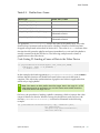
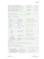
DOCUMENT CHANGE HISTORY
PG-03776-001_v06
Version
Date
Authors
Description of Change
01
January 24, 2008
TT, SM
Initial Release
02
August 14, 2009
TT, SM
• API Change
• New template
03
January 15, 2010
TT, SM
The following information added in this
revision:
Chapter 6 Ancillary Data
Chapter 14 Ancillary Data API
04
June 17, 2010
TT, SM
05
November 8, 2010
TT, SM
06
May 26, 2011
Quadro SDI Output
TT, SM
• Change to the code in Chapter 12 NVAPI VIO
• Updated Code Listing 25
• Updated code in Section 6.2
• Added Section 6.4 Audio
• Updated Table 10-2
• Minor text edits
• Added Section 5.1 “GPU Selection”
• Added Sub-Section 6.4.3 “Determining the
Number of Audio Samples per Frame”
• Added Sub-Section 6.4.4 “Specifying Audio
Data”
• Added Sub-Section 10.3.4 “Color Space
Conversion”
• Minor text edits
• Updated Code Listing 32, Code Listing 33,
and Code Listing 35
• Added note to Sub-Section 6.4.4 “Specifying
Audio Data”
PG-03776-001_v06 | ii
TABLE OF CONTENTS
1 Getting Started
..................................................................... 1
2 Device Control APIs
..................................................................... 2
2.1
2.2
Windows .................................................................................. 2
Linux ...................................................................................... 2
3 OpenGL Extensions
..................................................................... 4
4 Device Setup and Control ..................................................................... 5
4.1
4.2
4.3
4.4
Initialize NVAPI ..........................................................................
Determining Video Capabilites ........................................................
Opening the Video Device .............................................................
Configuring the Video Device .........................................................
5 Data Transfer
5.1
5.2
5.3
5.4
5.5
5.6
5.7
5
6
7
8
.................................................................... 12
GPU Selection .......................................................................... 12
Buffer Object Initialization ........................................................... 13
Pbuffer Initialization .................................................................. 16
Starting Video Transfers .............................................................. 23
Sending FBO Data ...................................................................... 23
Sending Pbuffer Data .................................................................. 26
Stopping Video Transfers and Closing the Video Device ......................... 28
6 Ancillary Data
.................................................................... 30
6.1
Getting Started......................................................................... 30
6.2
Basics .................................................................................... 31
6.3
Time Code .............................................................................. 32
6.4
Audio .................................................................................... 33
6.4.1 SMPTE 272M – Standard Definition Audio ......................................... 34
6.4.2 SMPTE 299M – High Definition Audio............................................... 35
6.4.3 Determining the Number of Audio Samples per Frame ......................... 37
6.4.4 Specifying Audio Data ............................................................... 37
6.5
Custom Data ............................................................................ 40
6.6
Clean Up ................................................................................ 41
7 Video Compositing
7.1
7.2
7.3
.................................................................... 42
Alpha Compositing ..................................................................... 42
Chroma-Keying ......................................................................... 43
Luma-Keying ............................................................................ 45
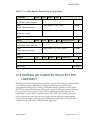
8 Changing the Video Device Configuration ............................................... 46
Quadro SDI Output
PG-03776-001_v06 | iii
9 Device Feedback
.................................................................... 47
9.1
Determining the Number of Queued Buffers ....................................... 47
9.1.1 Using the GLX/WGL_video_out Extension ........................................ 48
9.1.2 Using the GL_present_video Extension ........................................... 49
9.2
Detecting Duplicate Frames .......................................................... 51
9.2.1 Using the GLX/WGL_video_out Extension ........................................ 51
9.2.2 Using the GL_present_video Extension ........................................... 52
10 Advanced Topics
.................................................................... 53
10.1 Working with Two Video Channels .................................................. 53
10.1.1 Dual-Link Operation ................................................................ 53
10.1.2 Two Independent Video Channels ................................................ 53
10.2 Sending the Desktop to Video Output............................................... 54
10.3 Color space Conversion ............................................................... 55
10.3.1 Coefficients.......................................................................... 56
10.3.2 Scale
............................................................................ 56
10.3.3 Offset
............................................................................ 57
10.3.4 Typical Color Space Conversions ................................................. 61
10.4 Full-Scene Antialiasing ................................................................ 63
10.4.1 Pbuffer Multi-Sampling ............................................................ 63
10.4.2 Multi-Sampling with Buffer Objects .............................................. 65
10.5 Calculating Video Memory Usage .................................................... 66
10.6 Working with Greater Than 8 bits Per Component ................................ 67
10.7 Data Integrity Check .................................................................. 68
10.8 Composite Sync Termination ......................................................... 70
10.9 Specifying the Internal Buffer Queue Length ...................................... 71
11 NV_Present_video
.................................................................... 73
12 NVAPI VIO
.................................................................... 75
13 NV Control VIO Controls .................................................................. 105
14 Ancillary Data API
Quadro SDI Output
.................................................................. 133
PG-03776-001_v06 | iv
LIST OF TABLES
Table 5-1. Pbuffer Size = Field ................................................................. 26
Table 5-2. Pbuffer Size = Frame................................................................ 27
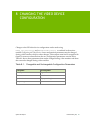
Table 8-1. Changeable and Unchangeable Configuration Parameters .................... 46
Table 10-1. SD ITU 601 Coefficients .......................................................... 56
Table 10-2. HD ITU 709 Coefficients .......................................................... 56
Table 10-3. Video Memory Required by an Application .................................... 67
Quadro SDI Output
PG-03776-001_v06 | v
1 GETTING STARTED
Application programming of the NVIDIA Quadro® FX SDI is broken into two principle
parts, device control and data transfer. Device control handles the hardware
configuration as well as the starting and stopping of data transfers while data transfer is
the sequence of operations that send graphics data to the video device for output.
The Quadro® FX SDI displays graphics data that has been rendered by the graphics
processing unit (GPU) into one or more OpenGL Frame Buffer Objects (FBO) or
application controlled pbuffers using traditional OpenGL programming techniques. The
resulting standard definition or high definition serial digital video output can be 8, 10, or
12-bit. 10-bit and 12-bit video output must originate from a 16-bit per-component
floating-point render target while 8-bit data can originate from either an 8-bit percomponent integer or a 16-bit per-component floating-point render target. Color data in
an 8-bit FBO or pbuffer should be integer data in the range of 0 to 255, while data placed
by an application into a 16-bit floating point pbuffer or FBO should be 16-bit float data
in the range of 0 to 1.
Quadro SDI Output
PG-03776-001_v06| 1
2 DEVICE CONTROL APIS
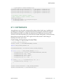
2.1 WINDOWS
On systems running the Microsoft Windows Operating System, hardware setup and
control is handled by the VIO commands of NVAPI, NVIDIA’s universal control API.
Use of NVAPI requires the inclusion of the following include and library files. These
files are packaged within the NVIDA Quadro SDI SDK.
nvapi.h
nvapi.lib
Use of the NVAPI to control the Quadro SDI device is described in Chapter 4 Device
Setup and Control. For additional information on NVAPI, refer to the NVAPI Online Help
documentation.
Note: Previous versions of the SDK utilized the NvCPL API for device control. This
API has been deprecated in favor of NVAPI in order to support Windows XP64,
Windows Vista and Windows 7.
2.2 LINUX
On Linux-based systems, hardware setup and control is enabled by the NV-CONTROL X
extension. Use of the NV-CONTROL X extension requires the following include files. These
files are packaged within the nvidia-settings-1.0.tar.gz archive that is included
with the NVIDIA SDI SDK or display driver.
NVCtrlLib.h
NVCtrl.h
Quadro SDI Output
PG-03776-001_v06| 2
Device Control APIs
Control of the Quadro SDI device with the NV-CONTROL X Extension is described in
Chapter 4 Device Setup and Control. Additional information on the NV-CONTROL X
Extension can be found in the NV-CONTROL-API.txt document included in the archive
listed previously.
Quadro SDI Output
PG-03776-001_v06 | 3
3 OPENGL EXTENSIONS
Data transfer is enabled by extensions to OpenGL. The GL_NV_present_video extension
provides a mechanism for the displaying of textures and renderbuffers on the Quadro
SDI output. This extension is supported on both Windows and Linux systems. The
WGL_NV_video_out extension sends pbuffers to the SDI device in the case of Windows
while the GLX_NV_video_out extension provides the same capabilities on Linux
systems. An application must utilize only one of the extensions as the two extensions
cannot be used together.
In addition to the OpenGL extensions, other useful extensions include the following:
ARB_occlusion_query
EXT_timer_query
EXT_framebuffer_object
ARB_pixel_format
ARB_pbuffer
NV_float_buffer
Note: The WGL_video_out or GLX_video_out OpenGL extensions cannot be
utilized with the GL_present_video OpenGL extension. An application must
choose and utilize a single programming paradigm.
Additional information on these OpenGL extensions can be found in the extension
specifications located at http://developers.nvidia.com or http://www.opengl.org/.
Quadro SDI Output
PG-03776-001_v06| 4
4 DEVICE SETUP AND CONTROL
Before graphics data can be transferred to the Quadro SDI for scan out as serial digital
video, the video device must be properly configured for the desired video signal format,
data format, timing, color space and genlock or framelock synchronization. This
hardware configuration is performed by NVAPI on Microsoft Windows-based systems
and the NV-CONTROL X extension on Linux-based systems. The remainder of this section
will describe the step by step process required to configure the video device. For
additional information on the functions described, refer to the NVAPI Online Help or NVCONTROL extension specification and included files.
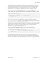
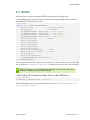
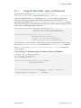
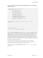
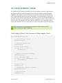
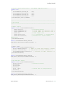
4.1 INITIALIZE NVAPI
Prior to using NVAPI on Windows, it is necessary to initialize NVAPI. This is done by
calling NvAPI_Initialize() as shown in the following Code Listing.
Code Listing 1: Initializing NVAPI
// Initialize NVAPI
if (NvAPI_Initialize() != NVAPI_OK) {
MessageBox(NULL, "Error Initializing NVAPI.", "Error", MB_OK);
return E_FAIL;
}
Note: Structures passed to NVAPI functions for returning NVAPI state must be
initialized to 0. This is done in the Code Listings in this document by calling
memset().
Quadro SDI Output
PG-03776-001_v06| 5
Device Setup and Control
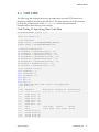
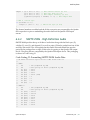
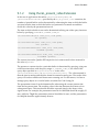
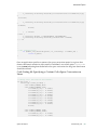
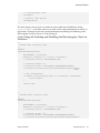
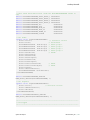
4.2 DETERMINING VIDEO CAPABILITES
On Windows, prior to configuring a video device, an application must query the
available video I/O topologies and locate a video device with the capability
NVVIOCAPS_VIDOUT_SDI. The procedure for doing this is outlined in Code Listing 2.
Once a video device with the desired capabilities is found, it is important to save the
VIO handle as this is the handle that will be passed to other NVAPI VIO functions for
configuring and controlling the device.
Code Listing 2: Locating an SDI Output Device on Windows
// Query Available Video I/O Topologies
memset(&l_vioTopos, 0, sizeof(l_vioTopos));
l_vioTopos.version = NVVIOTOPOLOGY_VER;
if (NvAPI_VIO_QueryTopology(&l_vioTopos) != NVAPI_OK) {
MessageBox(NULL, "Video I/O Unsupported.", "Error", MB_OK);
return E_FAIL;
}
// Cycle through all SDI topologies looking for the first
// available SDI output device topology.
l_bFound = FALSE;
i = 0;
while ((i < l_vioTopos.vioTotalDeviceCount) && (!l_bFound)) {
// Get video I/O capabilities for current video I/O target.
memset(&l_vioCaps, 0, sizeof(l_vioCaps));
l_vioCaps.version = NVVIOCAPS_VER;
if (NvAPI_VIO_GetCapabilities(l_vioTopos.vioTarget[i].hVioHandle,
&l_vioCaps) != NVAPI_OK) {
MessageBox(NULL, "Video I/O Unsupported.", "Error", MB_OK);
return E_FAIL;
}
// If video output device found, save VIO handle and set flag.
if (l_vioCaps.adapterCaps & NVVIOCAPS_VIDOUT_SDI) {
m_vioHandle = l_vioTopos.vioTarget[i].hVioHandle;
m_physicalGPU = l_vioTopologies.vioTarget[i].hPhysicalGpu;
l_bFound = TRUE;
} else {
i++;
}
} // while i < vioTotalDeviceCount
// If no video output device found, return error.
if (!l_bFound) {
MessageBox(NULL, "No SDI video output devices found.", "Error",
MB_OK);
return E_FAIL;
}
Quadro SDI Output
PG-03776-001_v06 | 6
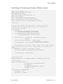
Device Setup and Control
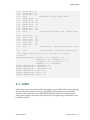
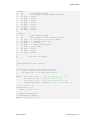
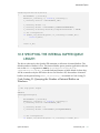
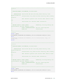
On Linux, use the XNVCTRLQueryAttribute function to query NV_CTRL_GVO_SUPPORTED
to determine if the X screen supports video output. This call will fail if video output is
not supported on the current X screen, or if the video output is already in use by the
desktop or another application.
Code Listing 3: Using NV_CONTROL-X Extension to Query Video
Output Capabilities
If (!XNVCTRLQueryAttribute(dpy, screen, 0,
NV_CTRL_GVO_SUPPORTED, &value)) {
return FALSE;
} else {
return TRUE;
}
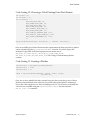
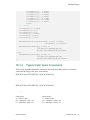
4.3 OPENING THE VIDEO DEVICE
Once the availability of a SDI video output device has been confirmed, the next step is to
open the video device by calling NvAPI_VIO_Open(). This is demonstrated in Code
Listing 4. In this example, NVVIOCLASS_SDI indicates that the device is an SDI device
while NVVIOOWNERTYPE_APPLICATION indicates that the device will be controlled by an
application rather than the desktop or NVIDIA control panel.
Code Listing 4: Opening the Video Device
// Open the video output device.
if (NvAPI_VIO_Open(m_vioHandle, NVVIOCLASS_SDI,
NVVIOOWNERTYPE_APPLICATION) != NVAPI_OK) {
MessageBox(NULL, "Cannot open SDI output device.", "Error",
MB_OK);
return E_FAIL;
}
Quadro SDI Output
PG-03776-001_v06 | 7
Device Setup and Control
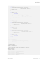
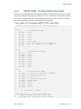
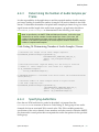
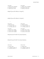
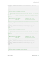
4.4 CONFIGURING THE VIDEO DEVICE
After opening a video device, the device must be configured for the desired video
output mode, format, timing, color space, genlock or frame lock characteristics and any
other required video parameters. Code Listing 5 shows a simple example of device
configuration for RGBA 4:4:4:4 input and 1080i YCrCbA 4:2:2:4 video output with
composite tri-level sync.
Note: On the Quadro SDI products, because both the analog and digital SDI sync
share a common BNC connector, the sync source (analog or SDI) must be specified,
before the incoming signal format can be detected.
Code Listing 5: Configuring a Video Device on Windows
NVVIOCONFIG l_vioConfig;
l_vioConfig.version = NVVIOCONFIG_VER;
l_vioConfig.nvvioConfigType = NVVIOCONFIGTYPE_OUT;
l_vioConfig.fields = NVVIOCONFIG_SIGNALFORMAT |
NVVIOCONFIG_DATAFORMAT |
NVVIOCONFIG_SYNCSOURCEENABLE |
NVVIOCONFIG_COMPOSITESYNCTYPE;
l_vioConfig.vioConfig.outConfig.signalFormat =
NVVIOSIGNALFORMAT_1080I_59_94_SMPTE274;
l_vioConfig.vioConfig.outConfig.dataFormat =
NVVIODATAFORMAT_R8B8B8A8_TO_YCRCBA4224;
l_vioConfig.vioConfig.outConfig.syncEnable = TRUE;
l_vioConfig.vioConfig.outConfig.syncSource =
NVGVOSYNCSOURCE_COMPSYNC;
// Set configuration
l_ret = NvAPI_VIO_SetConfig(m_vioHandle, &l_vioConfig);
if (l_ret != NVAPI_OK) {
return E_FAIL;
}
// Configure external sync parameters
NvU32 l_wait;
NVVIOSTATUS l_vioStatus;
l_vioConfig.fields = 0; // reset fields
// Trigger redetection of sync format
if (NvAPI_VIO_SyncFormatDetect(m_vioHandle, &l_wait)!= NVAPI_OK) {
return E_FAIL;
}
// Wait for sync detection to complete
Sleep(l_wait);
// Get sync signal format
l_vioStatus.version = NVVIOSTATUS_VER;
Quadro SDI Output
PG-03776-001_v06 | 8
Device Setup and Control
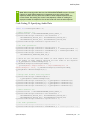
if (NvAPI_VIO_Status(m_vioHandle, &l_vioStatus) != NVAPI_OK) {
return E_FAIL;
}
// Verify that incoming sync is compatible with outgoing signal
if (frameLock) {
if (l_vioStatus.vioStatus.outStatus.syncFormat !=
l_vioConfig.vioConfig.outConfig.signalFormat) {
return E_FAIL;
}
l_vioConfig.vioConfig.outConfig.frameLockEnable = FALSE;
l_vioConfig.fields |= NVVIOCONFIG_FRAMELOCKENABLE;
} else { // Framelock Case
NvU32 l_compatible;
if (NvAPI_VIO_IsFrameLockModeCompatible(m_vioHandle,
l_vioStatus.vioStatus.outStatus.syncFormat,
l_vioConfig.vioConfig.outConfig.signalFormat,
&l_compatible) != NVAPI_OK) {
return E_FAIL;
}
}
if (l_compatible) {
l_vioConfig.vioConfig.outConfig.frameLockEnable =
TRUE;
l_vioConfig.fields |= NVVIOCONFIG_FRAMELOCKENABLE;
} else {
return E_FAIL;
}
l_vioConfig.vioConfig.outConfig.syncEnable =
l_vioStatus.vioStatus.outStatus.syncEnable;
l_vioConfig.vioConfig.outConfig.syncSource =
l_vioStatus.vioStatus.outStatus.syncSource;
switch(l_vioStatus.vioStatus.outStatus.syncSource) {
case NVVIOSYNCSOURCE_SDISYNC:
l_vioConfig.fields |= NVVIOCONFIG_SYNCSOURCEENABLE;
break;
case NVVIOSYNCSOURCE_COMPSYNC:
l_vioConfig.vioConfig.outConfig.compositeSyncType =
NVVIOCOMPSYNCTYPE_AUTO;
l_gvoConfig.fields |=
(NVVIOCONFIG_SYNCSOURCEENABLE |
NVVIOCONFIG_COMPOSITESYNCTYPE);
break;
} // switch
// Sync delay
NVVIOSYNCDELAY l_vioSyncDelay;
memset(&l_vioSyncDelay, 0, sizeof(l_vioSyncDelay));
l_vioSyncDelay.version = NVVIOSYNCDELAY_VER;
Quadro SDI Output
PG-03776-001_v06 | 9
Device Setup and Control
l_vioSyncDelay.horizontalDelay = hDelay;
l_vioSyncDelay.verticalDelay = vDelay;
l_vioConfig.fields |= NVVIOCONFIG_SYNCDELAY;
l_vioConfig.vioConfig.outConfig.syncDelay = l_gvoSyncDelay;
// Setup external sync
if (NvAPI_VIO_SetConfig(m_vioHandle, &l_vioConfig) != NVAPI_OK) {
return E_FAIL;
}
On Linux, the video device is configured using XNVCTRLSetAttribute. The following
example configures the video device for RGBA 4:4:4:4 input and 1080i YCrCbA 4:2:2:4
video output with composite tri-level sync.
Code Listing 6: Configuring a Video Device on Linux
screen = DefaultScreen(dpy);
// Set video signal format
XNVCTRLSetAttribute(dpy, screen, 0,
NV_CTRL_GVO_OUTPUT_VIDEO_FORMAT,
NV_CTRL_GVO_VIDEO_FORMAT_1080I_59_94_SMPTE274);
// Set video data format
XNVCTRLSetAttribute(dpy, screen, 0,
NV_CTRL_GVO_DATA_FORMAT,
NV_CTRL_GVO_DATA_FORMAT_R8G8B8A8_TO_YCRCBA4224);
// Enable genlock
XNVCTRLSetAttribute(dpy, screen, 0,
NV_CTRL_GVO_SYNC_MODE,
NV_CTRL_GVO_SYNC_MODE_GENLOCK);
// Set sync type to composite.
XNVCTRLSetAttribute(dpy, screen, 0,
NV_CTRL_GVO_SYNC_SOURCE,
NV_CTRL_GVO_SYNC_SOURCE_COMPOSITE);
XFlush(dpy);
// Sleep to allow time for sync detection
sleep(2);
// Detect input sync.
XNVCTRLQueryAttribute(dpy, screen, 0,
NV_CTRL_GVO_COMPOSITE_SYNC_INPUT_DETECTED,
&val);
// If valid sync detected, query input video format.
If (val) {
XNVCTRLQueryAttribute(dpy, screen
NV_CTRL_GVO_INPUT_VIDEO_FORMAT
Quadro SDI Output
PG-03776-001_v06 | 10
Device Setup and Control
}
Quadro SDI Output
&val);
PG-03776-001_v06 | 11
5 DATA TRANSFER
In programmable mode, the source for video output data is rendered into an 8-bit
integer or 16-bit floating point frame buffer object (FBO) or pbuffer render target. For 10bit or 12-bit video output, a 16-bit per-component floating-point render target must be
utilized. For 8-bit output, either an 8-bit integer or 16-bit floating-point per-component
render target may be used. An application may utilize a single render target or multiple
render targets configured in a ring buffer in order to send data to a single video device.
In order to send data to multiple video devices, multiple render targets are required.
This section describes the steps required to setup the render targets into which the
application should render OpenGL. An application should use either frame buffer
objects or pbuffers for data transfer and not combine the two techniques.
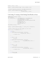
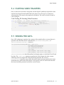
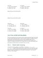
5.1 GPU SELECTION
In system configurations where there are multiple output device/GPU pairs present it is
important to make sure that the GPU and the output card that’s connected to that GPU
are addressed when configuring and using the output.
To do that the NvAPI/NVCtrl selection of the GPU should correspond to the OpenGL
selection.
On Windows this is done using the GPU affinity extension as illustrated in the following
code listing.
Quadro SDI Output
PG-03776-001_v06| 12
Data Transfer
Code Listing 7: Selecting the GPU that is connected to the Output
Card on Windows
while(wglEnumGpusNV(GPUindex,&GPUHandle)) // First call this
//function to get a handle to the gpu
{
//get detailed GPU info
while(wglEnumGpuDevicesNV(GPUHandle,DisplayIdx,&gpuDevice))
{
NvAPI_GetAssociatedNvidiaDisplayHandle(gpuDevice.DeviceName,
&hNvDisplay);
NvAPI_GetPhysicalGPUsFromDisplay(hNvDisplay,&hNvPhysicalGPU,
&count);
if(m_hPhysicalGpu == hNvPhysicalGPU)
{
//save the GPU affinity GPU handle to use
// for creating the OpenGL context
m_gpuHandle = GPUHandle;
break;
}
…
}
//Now an OpenGL context can be created
HGPUNV handles[2];
handles[0] = hGpu;
handles[1] = NULL;
// Create Affinity context
hDC = wglCreateAffinityDCNV(handles);
setPixelFormat(hDC);
// Create rendering context from the affinity device context
hRC = wglCreateContext(hDC);
// Make the affinity context current
wglMakeCurrent(hDC, hRC);
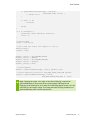
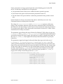
On Linux things are much simpler since all the important NVCtrl X extension calls and
the GLX context creating call are already using an X screen as one of the parameters.
5.2 BUFFER OBJECT INITIALIZATION
Use of the GL_NV_present_video extension to send GPU rendered content to the SDI
device requires the use of one or more buffer objects. These buffer objects can be texture
objects or renderbuffers bound to one or more frame buffer objects (FBOs). Creation of
an FBO with a texture or render buffer attachment is demonstrated in Code Listing 8.
Quadro SDI Output
PG-03776-001_v06 | 13
Data Transfer
Code Listing 8: Configuring a Frame Buffer Object
GLuint fboId;
GLuit textureObject;
GLuint renderbufferIds[2];
glGenRenderbuffersEXT(numRenderbuffers, renderbufferIds);
glBindRenderbufferEXT(GL_RENDERBUFFER_EXT, renderbufferIds[0]);
glRenderbufferStorageEXT(GL_RENDERBUFFER_EXT, GL_RGBA8,
width, height);
if (depth) {
glBindRenderbufferEXT(GL_RENDERBUFFER_EXT,
renderbufferIds[1]);
}
glRenderbufferStorageEXT(GL_RENDERBUFFER_EXT,
GL_DEPTH_COMPONENT,
width, height);
glGenFramebuffersEXT(1, &fboId);
glBindFramebufferEXT(GL_FRAMEBUFFER_EXT, fboId);
if (!textureObject) {
glFramebufferRenderbufferEXT(GL_FRAMEBUFFER_EXT,
GL_COLOR_ATTACHMENT0_EXT,
GL_RENDERBUFFER_EXT,
renderbufferIds[0]);
} else {
glBindTexture(GL_TEXTURE_RECTANGLE_NV, textureObject);
glFramebufferTexture2DEXT(GL_FRAMEBUFFER_EXT,
GL_COLOR_ATTACHMENT0_EXT,
GL_TEXTURE_RECTANGLE_NV,
textureObject, 0 );
}
if (depth) {
glFramebufferRenderbufferEXT(GL_FRAMEBUFFER_EXT,
GL_DEPTH_ATTACHMENT_EXT,
GL_RENDERBUFFER_EXT,
renderbufferIds[1]);
}
glBindRenderbufferEXT(GL_RENDERBUFFER_EXT, 0);
glBindFramebufferEXT(GL_FRAMEBUFFER_EXT, 0);
Quadro SDI Output
PG-03776-001_v06 | 14
Data Transfer
Creation of an FBO is identical on both Windows and Linux, and requires only a current
OpenGL context. In the previous code listing example, when a texture object is specified,
it is attached as COLOR_ATTACHMENT0, otherwise, a renderbuffer is used. For more
information on FBO creation and usage, refer to the GL_EXT_framebuffer_object
specification.
In order for an application to render into an FBO render target, the target must first be
bound using the command in Code Listing 9.
Code Listing 9: Configuring a Frame Buffer Object
glBindFramebufferEXT(GL_FRAMEBUFFER_EXT, fboId);
Either before or after buffer object creation, the SDI video device must be bound in
OpenGL. The procedure for enumerating the available video devices and binding one of
them is outlined in Code Listing 10.
Code Listing 10: Binding a Video Device
// Enumerate the available video devices and
// bind to the first one found
HVIDEOOUTPUTDEVICENV *videoDevices;
// Get list of available video devices.
int numDevices = wglEnumerateVideoDevicesNV(ghWinDC, NULL);
if (numDevices <= 0) {
MessageBox(NULL, "wglEnumerateVideoDevicesNV() did not return
any devices.", "Error", MB_OK);
exit(1);
}
videoDevices = (HVIDEOOUTPUTDEVICENV *)malloc(numDevices *
sizeof(HVIDEOOUTPUTDEVICENV));
if (!videoDevices) {
fprintf(stderr, "malloc failed.
exit(1);
}
OOM?");
if (numDevices != wglEnumerateVideoDevicesNV(ghWinDC,
videoDevices)) {
free(videoDevices);
MessageBox(NULL, "Invonsistent results from
wglEnumerateVideoDevicesNV()", "Error", MB_OK);
exit(1);
}
//Bind the first device found.
if (!wglBindVideoDeviceNV(ghWinDC, 1, videoDevices[0], NULL)) {
free(videoDevices);
Quadro SDI Output
PG-03776-001_v06 | 15
Data Transfer
}
MessageBox(NULL, "Failed to bind a videoDevice to slot 0.\n",
"Error", MB_OK);
exit(1);
// Free list of available video devices, don't need it anymore.
free(videoDevices);
5.3 PBUFFER INITIALIZATION
On Windows, the first step in the initialization of the pbuffer is to use the function
wglChoosePixelFormatARB() to choose a compatible pixel format. For Quadro SDI
video output from a pbuffer render target, the list of attributes specified as the second
argument to this function must include WGL_DRAW_TO_PBUFFER as well as one of
WGL_BIND_TO_VIDEO_RGB_NV, WGL_BIND_TO_VIDEO_RGBA_NV, or
WGL_BIND_TO_VIDEO_RGB_AND_DEPTH_NV. Code Listing 11 and Code Listing 12
illustrate this procedure for both the 8-bit and 16-bit cases.
Note: In the 16-bit floating point per-component case,
WGL_FLOAT_COMPONENTS_NV must also be specified in the attribute list.
Code Listing 11: Choosing an 8-bit Pixel Format
int format = 0;
int nformats = 0;
int attribList = {
WGL_RED_BITS_ARB, 8,
WGL_GREEN_BITS_ARB, 8,
WGL_BLUE_BITS_ARB, 8,
WGL_ALPHA_BITS_ARB, 8,
WGL_STENCIL_BITS_ARB, 8,
WGL_DEPTH_BITS_ARB, 24,
WGL_DRAW_TO_PBUFFER_ARB, true,
WGL_BIND_TO_VIDEO_RGBA_NV, true,
0 };
wglChoosePixelFormatARB(hDC, attribList, 1, &format, &nformats);
Quadro SDI Output
PG-03776-001_v06 | 16
Data Transfer
Code Listing 12: Choosing a 16-bit Floating Point Pixel Format
int format = 0;
int nformats = 0;
int attribList = {
WGL_RED_BITS_ARB, 16,
WGL_GREEN_BITS_ARB, 16,
WGL_BLUE_BITS_ARB, 16,
WGL_ALPHA_BITS_ARB, 16,
WGL_STENCIL_BITS_ARB, 8,
WGL_DEPTH_BITS_ARB, 24,
WGL_DRAW_TO_PBUFFER_ARB, true,
WGL_BIND_TO_VIDEO_RGBA_NV, true,
WGL_FLOAT_COMPONENTS_NV, true,
0}
wglChoosePixelFormat(hDC, attribList, 1, &format, &nformats);
Once an available pixel format that meets the requirements has been specified, a pbuffer
can be created using the wglCreatePbufferARB() function. For video output, the
attribute list specified as the final argument must contain one of
WGL_BIND_TO_VIDEO_RGB_NV, WGL_BIND_TO_VIDEO_RGBA_NV, or
WGL_BIND_TO_VIDEO_RGB_AND_DEPTH_NV. Code Listing 13 demonstrates pbuffer
creation.
Code Listing 13: Creating a Pbuffer
attribList[0] = WGL_BIND_TO_VIDEO_RGBA_NV;
attribList[1] = true;
attribList[2] = 0;
hPbuf = wglCreatePbufferARB(hDC, format, width, height,
attribList);
Once one or more pbuffers has been created using the above procedure, each of these
pbuffers must be bound to the video device so that subsequent OpenGL rendering is
sent to the video output device. Prior to binding however, it is necessary to identify the
video devices available using the wglGetVideoDeviceNV() function from the
WGL_NV_video_out extension.
Quadro SDI Output
PG-03776-001_v06 | 17
Data Transfer
Code Listing 14: Get Video Devices Available on the System
HPVIDEODEV hpDevList;
if ((wglGetVideoDeviceNV(hDC, 1, &hpDevList) != GL_NOERROR) {
}
// Handle error.
Once a video device has been identified, bind the application pbuffers using the
wglBindVideoImageNV() command. The final argument to this function must be one of
WGL_VIDEO_OUT_COLOR_NV, WGL_VIDEO_OUT_ALPHA_NV,
WGL_VIDEO_OUT_COLOR_AND_ALPHA_NV or WGL_VIDEO_OUT_COLOR_AND_DEPTH._NV.
This argument specifies the data within the pbuffer that will ultimately get transferred
to the video out device. In Code Listing 15, the color and alpha portions of the pbuffer
specified by hPbuf are bound to the video device.
Code Listing 15: Binding a Pbuffer to a Video Device
if ((wglBindVideoImageNV(hpDevList, hPbuf,
WGL_VIDEO_OUT_COLOR_AND_ALPHA) != GL_NOERROR) {
}
// Handle error.
On Linux, a pbuffer is created using a combination of glxChooseFBConfig() to choose
compatible frame buffer configurations and glXCreatePbuffer() to create a pbuffer of
the width and height required. This process for both an 8-bit integer and a 16-bit floating
point pbuffer is outlined in Code Listing 16 and Code Listing 17.
Note: Once glXChooseFBConfig returns the list of compatible frame buffer
configurations, an application must traverse the list to find a configuration of the
desired color depth.
Code Listing 16: Creating an 8-bit Pbuffer on Linux
GLXFBConfig *configs, config;
int nelements;
int config_list[] = { GLX_DRAWABLE_TYPE, GLX_PBUFFER_BIT,
GLX_ALPHA_SIZE, 8,
GLX_DOUBLE_BUFFER, GL_TRUE,
GLX_RENDER_TYPE, GLX_RGBA_BIT,
None };
int pbuffer_list[8];
configs = glXChooseFBConfig(dpy, 0, config_list, &nelements);
// Find a config with the right number of color bits.
for (i = 0; i < nelements; i++) {
Quadro SDI Output
PG-03776-001_v06 | 18
Data Transfer
int attr;
if (glXGetFBConfigAttrib(dpy, configs[i],
GLX_RED_SIZE, &attr)) {
// Handle error
}
if (attr != 8)
continue;
if (glXGetFBConfigAttrib(dpy, configs[i],
GLX_GREEN_SIZE, &attr)) {
// Handle error
}
if (attr != 8)
continue;
if (glXGetFBConfigAttrib(dpy, configs[i],
GLX_BLUE_SIZE, &attr)) {
// Handle error
}
if (attr != 8)
continue;
if (glXGetFBConfigAttrib(dpy, configs[i],
GLX_ALPHA_SIZE, &attr)) {
// Handle error
if (attr != 8)
continue;
}
break;
if (i == nelements) {
printf("No 8-bit FBConfigs found\n");
return -1;
}
// Config found
config = configs[i];
// Don't need the config list anymore so free it.
XFree(configs);
configs = NULL;
pbuffer_list[0]
pbuffer_list[1]
pbuffer_list[2]
pbuffer_list[3]
Quadro SDI Output
=
=
=
=
GLX_PBUFFER_WIDTH;
gWidth;
GLX_PBUFFER_HEIGHT;
gHeight;
PG-03776-001_v06 | 19
Data Transfer
pbuffer_list[4] = None;
pbuffer = glXCreatePbuffer(dpy, config, pbuffer_list);
// Create rendering context for GLX_RGBA_TYPE pbuffer.
context = glXCreateNewContext(dpy, config,
GLX_RGBA_TYPE, 0, True);
Code Listing 17: Creating a 16-bit Floating Point Pbuffer on Linux
GLXFBConfig *configs, config;
int nelements;
int config_list[] = { GLX_DRAWABLE_BIT, GLX_PBUFFER_BIT,
GLX_DOUBLEBUFFER, GL_TRUE,
GLX_RENDER_TYPE, GLX_RGBA_FLOAT_BIT_ARB,
GLX_RED_SIZE, 16,
GLX_GREEN_SIZE, 16,
GLX_BLUE_SIZE, 16,
None };
int pbuffer_list[8];
configs = glXChooseFBConfig(dpy, 0, config_list, &nelements);
// Find a config with the right number of color bits.
for (i = 0; i < nelements; i++) {
int attr;
if (glXGetFBConfigAttrib(dpy, configs[i],
GLX_RED_SIZE, &attr)) {
// Handle error
}
if (attr != 16)
continue;
if (glXGetFBConfigAttrib(dpy, configs[i],
GLX_GREEN_SIZE, &attr)) {
// Handle error
}
if (attr != 16)
continue;
if (glXGetFBConfigAttrib(dpy, configs[i],
GLX_BLUE_SIZE, &attr)) {
// Handle error
}
if (attr != 16)
continue;
Quadro SDI Output
PG-03776-001_v06 | 20
Data Transfer
if (glXGetFBConfigAttrib(dpy, configs[i],
GLX_ALPHA_SIZE, &attr)) {
// Handle error
}
if (attr != 16)
continue;
}
break;
if (i == nelements) {
printf("No 16-bit FBConfigs found\n");
return -1;
}
// Config found
config = configs[i];
// Don't need the config list anymore so free it.
XFree(configs);
configs = NULL;
pbuffer_list[0]
pbuffer_list[1]
pbuffer_list[2]
pbuffer_list[3]
pbuffer_list[4]
=
=
=
=
=
GLX_PBUFFER_WIDTH;
gWidth;
GLX_PBUFFER_HEIGHT;
gHeight;
None;
// Create pbuffer
pbuffer = glXCreatePbuffer(dpy, config, pbuffer_list);
// Create rendering context for GLX_RGBA_FLOAT_TYPE_ARB pbuffer.
context = glXCreateNewContext(dpy, config,
GLX_RGBA_FLOAT_TYPE_ARB, 0, True);
Note: Checking the proper color depth of the chosen FBConfig is required as
glXChooseFBConfig in recent Linux drivers returns deeper FBConfigs at the
beginning of the resulting list. As a result 32-bit FBConfigs appear earlier in the list
than FP16 or 8-bit integer configs. The change was made to bring the behavior of
glXChooseFBConfig inline with the specification.
Quadro SDI Output
PG-03776-001_v06 | 21
Data Transfer
After creating one or more pbuffers using the procedure described in Code Listing 17,
each of these pbuffers must be bound to the video device so that subsequent OpenGL
rendering into that pbuffer is sent to the video output device. Prior to binding the
pbuffer however, it is necessary to identify the video devices available using the
glXGetVideoDeviceNV() function from the GLX_NV_video_out extension.
Code Listing 18: Getting Video Devices Available on a Linux System
GLXVideoDeviceNV video_device;
if (glXGetVideoDeviceNV(dpy, 0, 1, &video_device) {
// Handle error.
}
Once a video device has been identified, bind the application pbuffers using the
glXBindVideoImageNV() command. The final argument to this function must be one of
GLX_VIDEO_OUT_COLOR_NV, GLX_VIDEO_OUT_ALPHA_NV,
GLX_VIDEO_OUT_COLOR_AND_ALPHA_NV or GLX_VIDEO_OUT_COLOR_AND_DEPTH_NV. This
argument specifies the data within the pbuffer that will ultimately get transferred to the
video out device. In Code Listing 19, the color and alpha portions of the pbuffer
specified by hPbuf are bound to the video device.
Code Listing 19: Binding a Pbuffer to a Linux Video Device
if (glXBindVideoImageNV(dpy, video_device,
pbuffer, GLX_VIDEO_OUT_COLOR_NV)) {
// Handle error.
}
Once the pbuffers are bound to the video device, video transfers can be started as
described in Starting Video Transfers. The procedure for sending frames/fields of data to
the device is described in the section entitled Sending FBO Data and Sending Pbuffer Data.
Quadro SDI Output
PG-03776-001_v06 | 22
Data Transfer
5.4 STARTING VIDEO TRANSFERS
Once a video device has been configured, and the OpenGL pbuffer(s) required for data
transfer have been allocated and bound to the device, the next step is to commence
video transfers. This step is only required on Windows. The code to do this is listed in
Code Listing 20.
Code Listing 20: Starting VideoTransfers
if (( m_vioHandle ) && !(NvAPI_VIO_IsRunning(m_vioHandle))){
if ( NvAPI_VIO_Start( m_vioHandle ) != NVAPI_OK ) {
MessageBox(NULL, "Error starting video devices.",
"Error", MB_OK);
return E_FAIL;
}
}
5.5 SENDING FBO DATA
Once GPU rendering is complete, the contents of the render buffer or texture objects is
queued to the SDI video device with either the glPresentFrameKeyedNV() or
glPresentFrameDualFillNV() functions.
void glPresentFrameKeyedNV(uint video_slot,
uint64EXT minPresentTime,
uint beginPresentTimeId,
uint presentDurationId,
enum type,
enum target0, uint fill0, uint key0,
enum target1, uint fill1, uint key1);
glPresentFrameKeyedNV should be utilized to display single- or dual-link fill or fill and
key data. The video_slot parameter specifies the video output slot in the current
rendering context on which this frame should be presented. The value of
minPresentTime should be set to either the earliest time in nanoseconds that the frame
should become visible on the SDI output, or the special value of 0 which indicates that
the frame should be presented at the next vertical retrace.
Quadro SDI Output
PG-03776-001_v06 | 23
Data Transfer
Frame presentation is always queued until the vertical blanking period of the SDI
device. At that time, the SDI device will display the:
Last presented frame if there are no additional frames queued to present.
Next frame in the queue with the minimum presentation time of 0.
The last frame in the queue that has a minimum presentation time past the current
time.
Queued frames are always consumed in the order in which they were sent. Any
consumed frames not displayed are discarded.
The values of beginPresentTimeId and presentDurationId represent valid query
objects. These should be utilized to query the time at which the frame is displayed on
the SDI device and the number of vertical retrace intervals that the frame was presented.
Use of these query objects will be discussed in more detail in Section 8.1.2. These values
should be set to 0 if they are unused.
The parameter type indicates the type of data to be displayed. Valid values for type are
GL_FIELDS_NV and GL_FRAME_NV. When GL_FIELDS_NV is specified, both fields must be
specified by target0, fill0, key0, target1, fill1 and key1 in order to complete the frame. In
the case of GL_FRAME_NV, only target0, fill0 and key0 should be utilized to specify the
frame data.
The parameters target0 and target1 indicate the data object type and can be one of
GL_TEXTURE_2D, GL_TEXTURE_RECTAGLE, GL_RENDERBUFER_EXT or GL_NONE. The
values of fill0 and fill1 name the objects of the corresponding type from which the color
data will be read while key0 and key1 name the objects from which the key channel data
will be read. In the case that there is no key channel data to display, the values of key0
and key1 should be set to GL_NONE. In this case, the key data is taken from the alpha
channel of the specified fill object. In the case that the type specified is GL_FRAME_NV,
target1, fill1 and key1 should be specified as GL_NONE.
void glPresentFrameDualFillNV(uint video_slot,
uint64EXT minPresentTime,
uint beginPresentTimeId,
uint presentDurationId,
enum type,
enum target0, uint fill0,
enum target1, uint fill1,
enum target2, uint fill2,
enum target3, uint fill3);
Quadro SDI Output
PG-03776-001_v06 | 24
Data Transfer
glPresentFrameDualFillNV() should be utilized to display two channels of singlelink fill data. This operating mode is useful for presenting two completely different fill
channels or two fill channels in stereo, where one eye is presented on one channel while
the other eye is presented on the other SDI channel.
glPresentFrameDualFillNV() operates similarly to PresentFrameKeyedNV()
described above. The parameters target0, fill0, target1 and fill1 specify the
data for the first SDI channel while target2, fill2, target3 and fill3 specify the
data for the second SDI channel. In the case that type is GL_FRAME_NV, only target0,
fill0, target2 and fill2 need to be specified with other parameters set to
GL_NONE. In the case of GL_FIELDS_NV, all parameters must be utilized to specify the
fields for each SDI channel.
The following code examples demonstrate the use of these functions. For more
information regarding these functions, please refer to the GL_NV_present_video
OpenGL extension specification.
In Code Listing 21, the contents of a texture object is interpreted as a complete frame
with the GL_FRAME_NV enum and displayed as both the video fill and key channels.
Code Listing 21: Sending a Texture Object to the Video Device
// Unbind frame buffer object
glBindFramebufferEXT(GL_FRAMEBUFFER_EXT, 0);
// Send texture object to SDI device
glPresentFrameKeyedNV(1, 0,
presentTimeID, presentDurationID,
GL_FRAME_NV,
GL_TEXTURE_RECTANGLE_NV, gTO, 0,
GL_NONE, 0, 0);
This code example, specifies that the texture object should be displayed on video slot 1
at the next vertical retrace. The query objects presentTimeID and presentDurationID
return the time at which the frame is displayed on the SDI device and the number of
vertical retrace intervals during which the frame is displayed. These timer query objects
can then be utilized to determine if frame has been dropped or duplicated. More
information about synchronization and catching irregularities can be found in Section
8.1.2.
Code Listing 22 specifies the fill for two video channels for the case in which the Quadro
SDI is configured to display two fill channels rather than a fill and a key channel. In this
example, two render buffers containing complete frames are displayed on video slot 1 at
the next vertical retrace of the SDI device.
Quadro SDI Output
PG-03776-001_v06 | 25
Data Transfer
Code Listing 22: Sending Two Video Fill Channels
glBindFramebufferEXT(GL_FRAMEBUFFER_EXT, fbo1Id);
drawPattern1();
glBindFramebufferEXT(GL_FRAMEBUFFER_EXT, 0);
glBindFramebufferEXT(GL_FRAMEBUFFER_EXT, fbo2Id);
drawPattern2();
glBindFramebufferEXT(GL_FRAMEBUFFER_EXT, 0);
glPresentFrameDualFillNV(1, 0, 0, 0, GL_FRAME_NV,
GL_RENDERBUFFER_EXT, renderbuffer1Id,
GL_NONE, 0,
GL_RENDERBUFFER_EXT, renderbuffer2Id,
GL_NONE,0);
5.6 SENDING PBUFFER DATA
On Windows, an application sends graphics data to the video device by rendering
frames or fields into a pbuffer and then calling wglSendPbufferToVideoNV() to
indicate that OpenGL rendering is complete and that the pbuffer is ready to be scanned
out by the video device. The call to this function should typically be placed at the end of
the application draw loop.
BOOL wglSendPbufferToVideoNV (HPBUFFERARB hPbuffer,
int iBufferType,
unsigned long *pulCounterPbuffer,
BOOL bBlock);
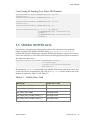
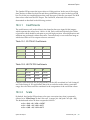
The parameter hPbuffer is the handle of the pbuffer. Both frames and fields can be sent
to the video device as indicated by the value of iBufferType and the relative size of the
pbuffer as outlined in Table 5-1 and Table 5-2.
Table 5-1. Pbuffer Size = Field
iBufferType
Pbuffer Size = Field
WGL_VIDEO_OUT_FIELD_1
Field 0
WGL_VIDEO_OUT_FIELD_2
Field 1
WGL_VIDEO_OUT_FRAME
Half height frame
WGL_VIDEO_OUT_STACKED_FIELDS_1_2
Half height frame
WGL_VIDEO_OUT_STACKED_FIELDS_2_1
Half height frame
Quadro SDI Output
PG-03776-001_v06 | 26
Data Transfer
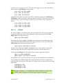
Table 5-2. Pbuffer Size = Frame
iBufferType
Pbuffer Size = Frame
WGL_VIDEO_OUT_FIELD_1
Even lines to Field 0
WGL_VIDEO_OUT_FIELD_2
Odd lines to Field 1
WGL_VIDEO_OUT_FRAME
Full frame
WGL_VIDEO_OUT_STACKED_FIELDS_1_2
Upper half to Field 2
Bottom half to Field 1
WGL_VIDEO_OUT_STACKED_FIELDS_2_1
Upper half to Field 1
Bottom half to Field 2
The parameter pulCounterPbuffer returns the count of the pbuffer sent. This value
should always increment and can be used to calculate if frames or fields have been
dropped or duplicated as described in Section 8.1.1. The value of bBlock indicates if the
function should queue the pbuffer and return immediately or wait until the pbuffer is
actually scanned out by the SDI device. The following example sends a frame of
graphics data to the video device.
Code Listing 23: Sending a Frame of Data to the Video Device
if ((wglSendPbufferToVideoNV(hpBuf, WGL_VIDEO_OUT_FRAME,
&gBufCount, TRUE) != GL_NOERROR) {
// Handle error.
}
In this example, the fourth argument to wglSendPbufferToVideoNV() is set to TRUE to
indicate that this function call should block until video scan out of this frame is
complete. This aids in the synchronization of graphics and video in applications that
utilize only a single pbuffer.
Note: Color data in an 8-bit pbuffer should be integer data in the range of 1 to 256
while data placed by an application into a 16-bit floating point pbuffer should be
16-bit float data in the range of 0 to 1.
On Linux, the procedure of sending a pbuffer containing a field or frame to the video
output is identical to that for Windows except for the function used. On Linux, the
function glXSendPbufferToVideoNV() is utilized as illustrated in the following
example.
int glXSendPbufferToVideoNV(Display *dpy, GLXPbuffer pbuf,
int iBufferType,
unsigned long *pulCounterPbuffer,
GLboolean bBlock);
Quadro SDI Output
PG-03776-001_v06 | 27
Data Transfer
Code Listing 24: Sending a Frame of Data to the Linux Video Device
glXSendPbufferToVideoNV(dpy, pbuffer,
GLX_VIDEO_OUT_FRAME_NV,
&gBufCount, GL_FALSE);
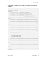
5.7 STOPPING VIDEO TRANSFERS AND CLOSING
THE VIDEO DEVICE
On Windows, once an application has completed all video transfers and no longer needs
access to a video device, an application should stop sending and release any OpenGL
resources prior to closing the device with NVAPI. If the WGL_video_out OpenGL
extension is in use, the pbuffer and video device should be released as shown in Code
Listing 25.
Code Listing 25: Releasing Bound OpenGL Resources
wglReleaseVideoImageNV(gPBuffer.getHandle(),
WGL_VIDEO_OUT_COLOR_AND_ALPHA_NV);
wglReleaseVideoDeviceNV(ghpDevList[0]);
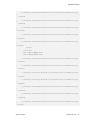
In the case of the GL_present_video extension, no formal releasing of OpenGL
resources is required. However, in both cases, once the OpenGL resources are released,
then the video device can be stopped and closed as shown in Code Listing 26.
Code Listing 26: Closing the Video Device on Windows
if ( m_vioHandle ) {
NvAPI_VIO_Close(m_vioHandle);
}
On Linux there are no requirements within the CONTROL-X extension to stop video
transfers and close the device. However, one must unbind any associated pbuffers and
release the video device using the appropriate GLX_NV_video_out functions, prior to
deleting the pbuffers. This is outlined Code Listing 27.
Quadro SDI Output
PG-03776-001_v06 | 28
Data Transfer
Code Listing 27: Releasing Bound OpenGL Resources on Linux
glXReleaseVideoImageNV(dpy, pbuffer);
glXReleaseVideoDeviceNV(dpy, 0, video_device);
glXDestroyPbuffer(dpy, pbuffer);
Quadro SDI Output
PG-03776-001_v06 | 29
6 ANCILLARY DATA
Ancillary data can be sent to the Quadro SDI device by using the NVIDIA SDI Ancillary
Data API. This API is defined in ANCapi.h in the SDK include directory. Applications
designed for the Microsoft Windows operating system must statically link against
ANCapi.lib. to utilize the ancillary data API. Linux application must link with
libanc.a. The library files can be found in the appropriate lib folder in the SDK. Since
the API is shared between Windows and Linux the details described in the remainder of
this chapter apply to both operating systems except where noted.
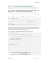
6.1 GETTING STARTED
Prior to sending ancillary data to the SDI device, the ancillary data API must be
initialized. This must be done after the OpenGL initialization of the SDI device.
Initialization is performed by calling the NvVIOANCAPI_InitializeGVO function.
Code Listing 28: Initializing Ancillary Data API on Windows
// Initialize ANC API
if (NvVIOANCAPI_InitializeGVO(gSDIout.getHandle()) != NVAPI_OK) {
return E_FAIL;
}
Code Listing 29: Initializing Ancillary Data API on Linux
// Initialize ANC API
if (NvVIOANCAPI_InitializeGVO(dpy, screen) == NVAPI_OK){
init = 1;
}
Quadro SDI Output
PG-03776-001_v06| 30
Ancillary Data
6.2 BASICS
Ancillary data is sent do the Quadro SDI device per frame by filling in the
corresponding fields in the following structure and setting the fields mask to indicate
those fields with valid data to be sent.
// Per Frame
typedef struct tagNVVIOANCDATAFRAME {
NvU32 version;
// Structure version
NvU32 fields;
// Field mask
NVVIOANCAUDIOGROUP AudioGroup1; // Audio group 1
NVVIOANCAUDIOGROUP AudioGroup2; // Audio group 2
NVVIOANCAUDIOGROUP AudioGroup3; // Audio group 3
NVVIOANCAUDIOGROUP AudioGroup4; // Audio group 4
NvU32 LTCTimecode;
// RP188
NvU32 LTCUserBytes;
NvU32 VITCTimecode;
NvU32 VITCUserBytes;
NvU32 FilmTimecode;
NvU32 FilmUserBytes;
NvU32 ProductionTimecode;
// RP201
NvU32 ProductionUserBytes;
// RP201
NvU32 FrameID;
NvU32 numCustomPackets;
NVVIOANCDATAPACKET *CustomPackets;
} NVVIOANCDATAFRAME;
Once the ancillary data for a frame has been placed into the structure it is sent to the SDI
device with the NvVIOANCAPI_SendANCData() function as shown in the Code Listing 30.
Note: As of Release 3.2 of the NVIDIA Quadro SDI SDK, only VITC and custom data
packets are supported by the ancillary data API.
Code Listing 30: Sending Ancillary Data to the SDI Device
// Send ANC data
NvVIOANCAPI_SendANCData(NULL, &ancData);
This call should be made by an application prior to call glPresentFrameKeyed() or
glPresentFrameDualFill().
Quadro SDI Output
PG-03776-001_v06 | 31
Ancillary Data
6.3 TIME CODE
The following code example shows how an application can send VITC time code as
defined by SMPTE 12M-1999 to the SDI device. The time code data as well as relevant
bit flags are packed into the 32-bit VITCTimecode field as documented and
demonstrated in the following code example.
Code Listing 31: Specifying Time Code Data
NVVIOANCDATAFRAME ancData = {0};
static int counter = 0;
// Set field mask
ancData.version = NVVIOANCDATAFRAME_VERSION;
ancData.fields = NVVIOANCDATAFRAME_VITC;
// Generate timecode here
int frameTens = myTimeCode.frame() / 10;
int frameUnits = myTimeCode.frame() % 10;
int secondTens = myTimeCode.second() / 10;
int secondUnits = myTimeCode.second() % 10;
int minuteTens = myTimeCode.minute() / 10;
int minuteUnits = myTimeCode.minute() % 10;
int hourTens = myTimeCode.hour() / 10;
int hourUnits = myTimeCode.hour() % 10;
// Set relevant bits here
short dropFrame = 1;
short colorFrame = 1;
short fieldPhase = 0;
short bg0 = 1;
short bg1 = 0;
short bg2 = 1;
// Per SMPTE 12M-1999, shift values to the appropriate
// bit positions.
//
// Bit Assigment
60-field TV 50-field TV 24-frame Film
// --- ---------------- ----------- ----------- ------------// 0
Frame Units (1)
// 1
Frame Units (2)
// 2
Frame Units (4)
// 3
Frame Units (8)
// 4
Frame Tens
(1)
// 5
Frame Tens
(2)
// 6
Flag
Drop Frame
Unused
Unused
// 7
Flag
Color Frame Color Frame Unused
// 8
Second Units (1)
// 9
Second Units (2)
// 10
Second Units (4)
// 11
Second Units (8)
Quadro SDI Output
PG-03776-001_v06 | 32
Ancillary Data
//
//
//
//
//
//
//
//
//
//
//
//
0
//
//
//
//
//
//
//
1
//
12
13
14
15
16
17
18
19
20
21
22
23
Second
Second
Second
Flag
Minute
Minute
Minute
Minute
Minute
Minute
Minute
Flag
24
25
26
27
28
29
30
Hours
Hours
Hours
Hours
Hours
Hours
Flag
31
Flag
Tens
Tens
Tens
Units
Units
Units
Units
Tens
Tens
Tens
Units
Units
Units
Units
Tens
Tens
(1)
(2)
(4)
(1)
(2)
(4)
(8)
(1)
(2)
(4)
(1)
(2)
(4)
(8)
(1)
(2)
Field/Phase
Binary Group 0 Phase
Binary Group 0 Binary Group 2 Binary Group
Binary Group 1
Binary Group 1 Binary Group
Binary Group 2
Field/Phase Binary Group 2
// For example only, not all bits are relevant for all signal
// formats.
ancData.VITCTimecode = hourTens << 29 | hourUnits << 25 |
minuteTens << 20 | minuteUnits << 16 |
secondTens << 12 | secondUnits << 8 |
frameTens << 4 | frameUnits;
ancData.VITCTimecode |= dropFrame << 6;
ancData.VITCTimecode |= colorFrame << 7;
ancData.VITCTimecode |= fieldPhase << 15;
ancData.VITCTimecode |= bg0 << 23;
ancData.VITCTimecode |= bg1 << 30;
ancData.VITCTimecode |= bg2 << 31;
6.4 AUDIO
Audio data is sent to the Quadro SDI output device as raw PCM audio samples package
into ancillary data packets according to the SMPTE 272M specification for standard
definition video signal formats or the SMPTE 299M specification for high definition
video signal formats. The Quadro SDI output devices supports up to 16 channels of 24bit audio at 48 KHz.
Quadro SDI Output
PG-03776-001_v06 | 33
Ancillary Data
6.4.1
SMPTE 272M – Standard Definition Audio
In the case of standard definition audio data, SMPTE 272M places up to 20-bits of audio
data along with the block sync (Z), validity (V), user (U), channel (C), and parity (P) bits
into a 32-bit AES subframe. The API requires that the 20-bit audio data and associated
bits also be packed into 32-bits as illustrated Code Listing 32.
Code Listing 32: Formatting SMPTE 272M Audio Data
//
//
//
//
//
//
//
//
//
//
//
//
//
//
//
//
//
//
//
//
//
//
//
//
//
//
//
//
//
//
//
//
//
//
//
//
//
//
//
SD Audio should be split across 3 ANC words like so:
X:
b9
b8
b7
b6
b5
b4
b3
b2
b1
b0
X+1:
b9
b8
b7
b6
b5
b4
b3
b2
b1
b0
X+2:
b9
b8
b7
b6
b5
b4
b3
b2
b1
b0
(b8)
(b7)
(b6)
(b5)
(b4)
(b3)
(b2)
(b1)
(b0)
-
!b8
aud
aud
aud
aud
aud
aud
ch1
ch0
Z
(Computed by HW)
5
4
3
2
1
0 (LSB)
00 = channel 1, 01 = channel 2,
10 = channel 3, 11 = channel 4
(b17)
(b16)
(b15)
(b14)
(b13)
(b12)
(b11)
(b10)
(b9)
-
!b8
aud
aud
aud
aud
aud
aud
aud
aud
aud
(Computed by FPGA)
14
13
12
11
10
9
8
7
6
(b26) (b25) (b24) (b23) (b22) (b21) (b20) (b19) (b18) ^
`- bit
!b8
P C U V aud
aud
aud
aud
aud
(Computed by FPGA)
Parity for bits 0-25 of sample.
Channel status bit.
User bit.
Sample validity bit.
19 (MSB)
18
17
16
15
order in 'sample'
// XXX Since we use a 16 bit audio source here
//
(input is NvU16), move the 16 bits into
//
the upper part of the audio data's 20 bits.
Quadro SDI Output
PG-03776-001_v06 | 34
Ancillary Data
sample = ((C & 0x1) << 25) |
((U & 0x1) << 24) |
((V & 0x1) << 23) |
((((NvU32)(*input))
// Add Z / block sync
if (curFrame == 0) {
sample |= (0x1 <<
}
0);
// AES channel status (C) bit
// AES user data (U) bit
// AES sample validity (V) bit
& 0xffff) << 7); // AES sample data
// AES block sync (Z bit)
The channel numbers are added and the 26-bit even parity are computed by the Quadro
SDI output device prior to embedding the audio data into the Quadro SDI output
stream.
6.4.2
SMPTE 299M – High Definition Audio
SMPTE 299M specifies that up to 24-bits of audio data along with the block sync (Z),
validity (V), user (U), and channel (C) as well as parity (P) bits be packed into four 10-bit
ancillary data words. The API requires that this audio data and related bits sans the
parity bits be packaged into a single 32-bit value for passing to the Quadro SDI output
device. The parity bits are computed by the Quadro SDI output device. This packaging
is shown in Code Listing 33.
Code Listing 33: Formatting SMPTE 299M Audio Data
// HD Audio should be split across 4 ANC words like so:
//
// UDWx:
//
b9
- !b8 (Computed by HW)
//
b8
- Even parity of b0-b7 (Computed by HW)
//
b7 (b7) - aud 3
//
b6 (b6) - aud 2
//
b5 (b5) - aud 1
//
b4 (b4) - aud 0 (LSB)
//
b3 (b3) - Z
//
b2 (b2) - 0
//
b1 (b1) - 0
//
b0 (b0) - 0
//
// UDWx+1:
//
b9
- !b8 (Computed by HW)
//
b8
- Even parity of b0-b7 (Computed by HW)
//
b7 (b15) - aud 11
//
b6 (b14) - aud 10
//
b5 (b13) - aud 9
//
b4 (b12) - aud 8
//
b3 (b11) - aud 7
//
b2 (b10) - aud 6
//
b1 (b9) - aud 5
//
b0 (b8) - aud 4
//
Quadro SDI Output
PG-03776-001_v06 | 35
Ancillary Data
// UDWx+2:
//
b9
//
b8
//
b7 (b23)
//
b6 (b22)
//
b5 (b21)
//
b4 (b20)
//
b3 (b19)
//
b2 (b18)
//
b1 (b17)
//
b0 (b16)
//
// UDWx+3:
//
b9
//
b8
//
b7 (b31)
//
b6 (b30)
//
b5 (b29)
//
b4 (b28)
//
b3 (b27)
//
b2 (b26)
//
b1 (b25)
//
b0 (b24)
//
^
//
`//
-
!b8 (Computed by HW)
Even parity of b0-b7 (Computed by HW)
aud 19
aud 18
aud 17
aud 16
aud 15
aud 14
aud 13
aud 12
-
!b8 (Computed by HW)
Even parity of b0-b7 (Computed by HW)
P - Parity for bits 0-30 of sample
C - Channel status bit.
U - User bit.
V - Sample validity bit.
aud 23 (MSB)
aud 22
aud 21
aud 20
bit order in 'sample'
//
// Add subframe for first channel.
//
// XXX Since we use a 16 bit audio source here
//
(input is NvU16), move the 16 bits into
//
the upper part of the audio data 24 bits.
sample = ((C & 0x1) << 30) |
((U & 0x1) << 29) |
((V & 0x1) << 28) |
((((NvU32)(*input))
// AES channel status (C) bit
// AES user data (U) bit
// AES sample validity (V) bit
& 0xffff) << 12); // AES sample data
// Add Z / block sync
if (curFrame == 0) {
sample |= (0x1 << 3);
}
// Compute and add parity
P = ComputeParity(sample);
sample |= (P & 0x1) << 31;
Quadro SDI Output
PG-03776-001_v06 | 36
Ancillary Data
6.4.3
Determining the Number of Audio Samples per
Frame
It is the responsibility of the application to send the required number of audio samples
per frame. Sending an insufficient number of samples will result in breaks in the audio
stream. To determine the number of required audio samples per frame for a given video
signal format and the length of the audio frame sequence, an application should use
NvVIOANCAPI_NumAudioSamples as demonstrated in the following code sample.
Note: As specified by the SMPTE 272M and 299M specifications, 1000/1001 signal
formats have an uneven number of audio samples per frame. In this case, the
number of audio samples per frame varies over a sequence of frames and the
position of the frame as specified by the frame sequence number dictates the
number of required audio samples.
Code Listing 34: Determining Number of Audio Samples / Frame
// Determine the length of the audio sample sequence.
NvVIOANCAPI_NumAudioSamples(getHandle(),
NVVIOANCAUDIO_SAMPLING_RATE_48_0,
(NvU32 *)&m_uiSequenceLength,
NULL);
// Allocate/reallocate required memory for the array to hold the
// number of audio samples for each frame in a sequence.
if (m_uiNumAudioSamples)
free(m_uiNumAudioSamples);
m_uiNumAudioSamples = (unsigned int*)calloc((size_t)m_uiSequenceLength,
sizeof(NvU32));
// Determine number of audio samples based on signal format
// and audio sampling rate.
NvVIOANCAPI_NumAudioSamples(getHandle(),
NVVIOANCAUDIO_SAMPLING_RATE_48_0,
(NvU32 *)&m_uiSequenceLength,
(NvU32 *)m_uiNumAudioSamples);
6.4.4
Specifying Audio Data
Once the raw PCM audio data is packed as described, it is inserted into the
NVVIOANCDATAFRAME structure as shown in Code Listing 35. Each group of four audio
channels also has an associated 32-bit control value. This 32-bit variable permits the
specification of the active channels, frame numbers and other controls within the SMPTE
per-frame audio control packet that accompanies the audio data packets for the specified
audio group.
Quadro SDI Output
PG-03776-001_v06 | 37
Ancillary Data
Note: When inserting audio data into the NVVIOANCDATAFRAME structure for each
frame in an audio frame sequence it is important to set the correct frame
sequence number and only insert the number of audio samples required for the
current frame. Not setting the correct frame sequence number or sending the
improper number of samples for the current frame will result in audio dropouts.
Code Listing 35: Specifying Audio Data
static int frameSequenceNum = 0;
// Audio Channels 1-4
m_AncData.fields |= NVVIOANCDATAFRAME_AUDIO_GROUP_1;
m_AncData.AudioGroup1.audioCntrl.activeChannels =
NVVIOANCAUDIO_ACTIVE_CH1 | NVVIOANCAUDIO_ACTIVE_CH2 |
NVVIOANCAUDIO_ACTIVE_CH3 | NVVIOANCAUDIO_ACTIVE_CH4;
m_AncData.AudioGroup1.audioCntrl.asynchronous = 1;
// Set audio parameters.
m_AncData.AudioGroup1.audioCntrl.asynchronous = 0;
m_AncData.AudioGroup1.audioCntrl.frameNumber1_2 = frameSequenceNum + 1;
m_AncData.AudioGroup1.audioCntrl.frameNumber3_4 = frameSequenceNum + 1;
m_AncData.AudioGroup1.audioCntrl.rate =
NVVIOANCAUDIO_SAMPLING_RATE_48_0;
// Check for the case where the number of valid samples does not match
// the number of audio samples expected for this frame in the sequence.
if (m_pRingBuffer->NumValidSamples(0) !=
m_uiNumAudioSamples[frameSequenceNum]) {
printf("Audio Sample Mismatch -- ExpectedNumSamples: %d
NumValidSamples: %d\n", m_uiNumAudioSamples[frameSequenceNum],
m_pRingBuffer->NumValidSamples(0));
}
// Assign data buffers from ring buffer
m_AncData.AudioGroup1.numAudioSamples =
m_pRingBuffer->NumValidSamples(0);
m_AncData.AudioGroup1.audioData[0] = m_pRingBuffer->GetBuffer(0);
m_AncData.AudioGroup1.audioData[1] = m_pRingBuffer->GetBuffer(1);
m_AncData.AudioGroup1.audioData[2] = m_pRingBuffer->GetBuffer(0);
m_AncData.AudioGroup1.audioData[3] = m_pRingBuffer->GetBuffer(1);
// Audio Channels 5-8
m_AncData.fields |= NVVIOANCDATAFRAME_AUDIO_GROUP_2;
m_AncData.AudioGroup2.audioCntrl.activeChannels =
NVVIOANCAUDIO_ACTIVE_CH1 | NVVIOANCAUDIO_ACTIVE_CH2 |
NVVIOANCAUDIO_ACTIVE_CH3 | NVVIOANCAUDIO_ACTIVE_CH4;
m_AncData.AudioGroup2.audioCntrl.asynchronous = 1;
// Set audio parameters.
m_AncData.AudioGroup2.audioCntrl.asynchronous = 0;
m_AncData.AudioGroup2.audioCntrl.frameNumber1_2 = frameSequenceNum + 1;
Quadro SDI Output
PG-03776-001_v06 | 38
Ancillary Data
m_AncData.AudioGroup2.audioCntrl.frameNumber3_4 = frameSequenceNum + 1;
m_AncData.AudioGroup2.audioCntrl.rate =
NVVIOANCAUDIO_SAMPLING_RATE_48_0;
// Assign data buffers from ring buffer
m_AncData.AudioGroup2.numAudioSamples =
m_pRingBuffer->NumValidSamples(0);
m_AncData.AudioGroup2.audioData[0] = m_pRingBuffer->GetBuffer(0);
m_AncData.AudioGroup2.audioData[1] = m_pRingBuffer->GetBuffer(1);
m_AncData.AudioGroup2.audioData[2] = m_pRingBuffer->GetBuffer(0);
m_AncData.AudioGroup2.audioData[3] = m_pRingBuffer->GetBuffer(1);
// Audio Channels 9-12
m_AncData.fields |= NVVIOANCDATAFRAME_AUDIO_GROUP_3;
m_AncData.AudioGroup3.audioCntrl.activeChannels =
NVVIOANCAUDIO_ACTIVE_CH1 | NVVIOANCAUDIO_ACTIVE_CH2 |
NVVIOANCAUDIO_ACTIVE_CH3 | NVVIOANCAUDIO_ACTIVE_CH4;
m_AncData.AudioGroup3.audioCntrl.asynchronous = 1;
// Set audio parameters.
m_AncData.AudioGroup3.audioCntrl.asynchronous = 0;
m_AncData.AudioGroup3.audioCntrl.frameNumber1_2 = frameSequenceNum + 1;
m_AncData.AudioGroup3.audioCntrl.frameNumber3_4 = frameSequenceNum + 1;
m_AncData.AudioGroup3.audioCntrl.rate =
NVVIOANCAUDIO_SAMPLING_RATE_48_0;
// Assign data buffers from ring buffer
m_AncData.AudioGroup3.numAudioSamples =
m_pRingBuffer->NumValidSamples(0);
m_AncData.AudioGroup3.audioData[0] = m_pRingBuffer->GetBuffer(0);
m_AncData.AudioGroup3.audioData[1] = m_pRingBuffer->GetBuffer(1);
m_AncData.AudioGroup3.audioData[2] = m_pRingBuffer->GetBuffer(0);
m_AncData.AudioGroup3.audioData[3] = m_pRingBuffer->GetBuffer(1);
// Audio Channels 13-16
m_AncData.fields |= NVVIOANCDATAFRAME_AUDIO_GROUP_4;
m_AncData.AudioGroup4.audioCntrl.activeChannels =
NVVIOANCAUDIO_ACTIVE_CH1 | NVVIOANCAUDIO_ACTIVE_CH2 |
NVVIOANCAUDIO_ACTIVE_CH3 | NVVIOANCAUDIO_ACTIVE_CH4;
m_AncData.AudioGroup4.audioCntrl.asynchronous = 1;
// Set audio parameters.
m_AncData.AudioGroup4.audioCntrl.asynchronous = 1;
m_AncData.AudioGroup4.audioCntrl.frameNumber1_2 = frameSequenceNum + 1;
m_AncData.AudioGroup4.audioCntrl.frameNumber3_4 = frameSequenceNum + 1;
m_AncData.AudioGroup4.audioCntrl.rate =
NVVIOANCAUDIO_SAMPLING_RATE_48_0;
// Assign data buffers from ring buffer
m_AncData.AudioGroup4.numAudioSamples =
Quadro SDI Output
PG-03776-001_v06 | 39
Ancillary Data
m_pRingBuffer->NumValidSamples(0);
m_AncData.AudioGroup4.audioData[0] = m_pRingBuffer->GetBuffer(0);
m_AncData.AudioGroup4.audioData[1] = m_pRingBuffer->GetBuffer(1);
m_AncData.AudioGroup4.audioData[2] = m_pRingBuffer->GetBuffer(0);
m_AncData.AudioGroup4.audioData[3] = m_pRingBuffer->GetBuffer(1);
// Increment frame sequence number.
// When sequence length reached, reset.
frameSequenceNum++;
if (frameSequenceNum == m_uiSequenceLength)
frameSequenceNum = 0;
6.5 CUSTOM DATA
An application can also send custom ancillary data packets. In this case, in addition to
specifying the custom data, an application must also specify the ancillary data packet
data identification (DID, secondary data identification (SDID) and data count (DC)
words as well as the checksum (CS) word for each custom data packet. Custom ancillary
data packets are placed in the VANC region of the video stream. Code Listing 36
illustrates how this can be done.
Code Listing 36: Specifying Custom Data
// Create custom packet(s)
ancData.fields |= NVVIOANCDATAFRAME_CUSTOM;
#define NUM_CUSTOM_PACKETS 255
NVVIOANCDATAPACKET customPackets[NUM_CUSTOM_PACKETS];
for (int i = 0; i < NUM_CUSTOM_PACKETS; i++) {
customPackets[i].version = NVVIOANCDATAPACKET_VERSION;
customPackets[i].DID = 0x69;
customPackets[i].SDID = 0x69;
customPackets[i].DC = 0xff;
customPackets[i].CS = 0x0; //
for (NvU8 j = 0; j < customPackets[i].DC; j++) {
customPackets[i].data[j] = j;
}
}
ancData.numCustomPackets = NUM_CUSTOM_PACKETS;
ancData.CustomPackets = &customPackets[0];
Quadro SDI Output
PG-03776-001_v06 | 40
Ancillary Data
6.6 CLEAN UP
When the video signal format changes, an application must release and then reinitialize
the ancillary data API. This is necessary in order for the state to be set properly for the
new video signal format. The API is release by calling NvVIOANCAPI_ReleaseGVO().
Quadro SDI Output
PG-03776-001_v06 | 41
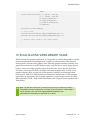
7 VIDEO COMPOSITING
The Quadro SDI supports programmable 2D compositing. This operating mode
combines the image data from the incoming video stream with the GPU-rendered image
based upon the values in a third image known as a matte or key channel. The Quadro
SDI supports the following compositing methods.
Note: 2D compositing is any supported when the signal format of the incoming
video matches the outgoing signal format and the outgoing SDI video signal is
genlocked to the input signal. Scaling or retiming the video input to match the
video output signal format is not supported.
7.1 ALPHA COMPOSITING
In the case of alpha compositing, the application provides the key / matte channel per
field / frame in the alpha channel of the OpenGL graphics stream. When the application
enables alpha compositing via the API, the Quadro SDI simply executes the function
below to compute the final pixel color.
output color = input video color * (1 - alpha) + input graphics color * (alpha)
When the value of the key or matte is strictly 1 or 0, the compositing is complete
replacement. When the key value is between 0 and 1, the two images (video and
graphics) would be blended. The above formula is executed for each and every pixel in
the SDI output stream.
Quadro SDI Output
PG-03776-001_v06| 42
Video Compositing
In configuration of the SDI device, alpha compositing is enabled as follows:
l_vioConfig.fields = 0;
l_vioConfig.fields = NVVIOCONFIG_COMPOSITE;
l_vioConfig.vioConfig.outConfig.enableComposite = TRUE;
l_vioConfig.fields = NVVIOCONFIG_ALPHAKEYCOMPOSITE;
l_vioConfig.vioConfig.outConfig.enableAlphaKeyComposite |= TRUE;
if (NvAPI_VIO_SetConfig(m_vioHandle, &l_vioConfig)!= NVAPI_OK) {
return E_FAIL;
}
OpenGL must be configured to provide an alpha channel to the SDI device. In the case
of sending pbuffer data with WGL/GLX_send_video this is done by specifying
VIDEO_OUT_COLOR_AND_ALPHA to the bind command as follows:
// Bind pbuffer to video device.
if (!wglBindVideoImageNV(ghpDevList[0], gPBuffer.getHandle(),
WGL_VIDEO_OUT_COLOR_AND_ALPHA_NV)) {
// Handle error.
}
In the case of the GL_present_video extension, the format of the buffer object or texture
must contain an alpha channel. Typical formats to create such a buffer object or texture
would be either GL_RGBA8 or GL_RGBA16F_ARB.
7.2 CHROMA-KEYING
To perform chroma keying, the application can specify up to two (Cr,Cb) pairs that
represent the starting and ending chroma values for replacement within the video
stream. Chroma keying is enabled with the ranges specified using the control API as
follows.
// Cr composite ranges
l_vioConfig.fields = 0; // reset fields
l_vioConfig.fields = NVVIOCONFIG_COMPOSITE |
NVVIOCONFIG_COMPOSITE_CR;
l_vioConfig.vioConfig.outConfig.enableComposite = TRUE;
l_vioConfig.vioConfig.outConfig.compRange.uEnabled = TRUE;
l_vioConfig.vioConfig.outConfig.compRange.uRange = 0;
l_vioConfig.vioConfig.outConfig.compRange.uMin = crCompRange[0];
l_vioConfig.vioConfig.outConfig.compRange.uMax = crCompRange[1];
if (NvAPI_VIO_SetConfig(m_vioHandle, &l_vioConfig)!= NVAPI_OK) {
return E_FAIL;
}
l_vioConfig.vioConfig.outConfig.compRange.uRange = 1;
Quadro SDI Output
PG-03776-001_v06 | 43
Video Compositing
l_vioConfig.vioConfig.outConfig.compRange.uMin = crCompRange[2];
l_vioConfig.vioConfig.outConfig.compRange.uMax = crCompRange[3];
if (NvAPI_VIO_SetConfig(m_vioHandle, &l_vioConfig)!= NVAPI_OK) {
return E_FAIL;
}
// Cb composite ranges
l_vioConfig.fields = 0; // reset fields
l_vioConfig.fields = NVVIOCONFIG_COMPOSITE |
NVVIOCONFIG_COMPOSITE_CB;
l_vioConfig.vioConfig.outConfig.enableComposite = TRUE;
l_vioConfig.vioConfig.outConfig.compRange.uEnabled = TRUE;
l_vioConfig.vioConfig.outConfig.compRange.uRange = 0;
l_vioConfig.vioConfig.outConfig.compRange.uMin = cbCompRange[0];
l_vioConfig.vioConfig.outConfig.compRange.uMax = cbCompRange[1];
if (NvAPI_VIO_SetConfig(m_vioHandle, &l_vioConfig)!= NVAPI_OK) {
return E_FAIL;
}
l_vioConfig.vioConfig.outConfig.compRange.uRange = 1;
l_vioConfig.vioConfig.outConfig.compRange.uMin = cbCompRange[2];
l_vioConfig.vioConfig.outConfig.compRange.uMax = cbCompRange[3];
if (NvAPI_VIO_SetConfig(m_vioHandle, &l_vioConfig)!= NVAPI_OK) {
return E_FAIL;
}
When the application enables chroma keying, the Quadro SDI examines the chroma (Cr
and Cb) for each incoming video pixel. If the (Cr, Cb) value for that pixel is within one of
the specified ranges, the color of that pixel is replaced with the pixel color from the GPU.
Quadro SDI Output
PG-03776-001_v06 | 44
Video Compositing
7.3 LUMA-KEYING
For luma keying, the application specifies up to two pairs of luma (Y) values via the API.
These values represent the starting and ending luma values for replacement. Luma
keying is enabled with the range specified as follows.
// Y composite ranges
l_vioConfig.fields = 0; // reset fields
l_vioConfig.fields = NVVIOCONFIG_COMPOSITE |
NVVIOCONFIG_COMPOSITE_Y;
l_vioConfig.vioConfig.outConfig.enableComposite = TRUE;
l_vioConfig.vioConfig.outConfig.compRange.uEnabled = TRUE;
l_vioConfig.vioConfig.outConfig.compRange.uRange = 0;
l_vioConfig.vioConfig.outConfig.compRange.uMin = yCompRange[0];
l_vioConfig.vioConfig.outConfig.compRange.uMax = yCompRange[1];
if (NvAPI_VIO_SetConfig(m_vioHandle, &l_vioConfig)!= NVAPI_OK) {
return E_FAIL;
}
l_vioConfig.vioConfig.outConfig.compRange.uRange = 1;
l_vioConfig.vioConfig.outConfig.compRange.uMin = yCompRange[2];
l_vioConfig.vioConfig.outConfig.compRange.uMax = yCompRange[3];
if (NvAPI_VIO_SetConfig(m_vioHandle, &l_vioConfig)!= NVAPI_OK) {
return E_FAIL;
}
When luma compositing is enabled, the Quadro SDI compares the luma (Y) for each
incoming video pixel to the specified ranges. If the value for that pixel is within a
specified range, the color or that pixel is replaced with the pixel color from the GPU.
Quadro SDI Output
PG-03776-001_v06 | 45
8 CHANGING THE VIDEO DEVICE
CONFIGURATION
Changes to the SDI video device configuration can be made using
NvAPI_VIO_SetConfig() and XNVCTRLSetAttribute() as outlined in the section
entitled Configuring the Video Device. Some configuration parameters may be changed
during video transfers while for other changes, video output must first be stopped with
OpenGL resources released before the new configuration parameters can take affect.
Table 8-1 shows those parameters that maybe changed during video transfers and those
that cannot be changed during video transfers.
Table 8-1. Changeable and Unchangeable Configuration Parameters
Changeable
Unchangeable
Color space conversion
Signal format
Gamma correction
Data format
Synchronization
Flip queue length
Compositing
Quadro SDI Output
PG-03776-001_v06| 46
9 DEVICE FEEDBACK
The WGL_NV_video_out/GLX_NV_video_out as well as the GL_NV_present_video
extensions provides device feedback. This functionality provides the following
information to the calling application.
Number of buffers queued for SDI scanout.
Vertical retrace interval count.
Time at which a frame was scanned out.
Number of vertical retrace intervals during which the same frame was scanned out.
This information can subsequently be used by an application to determine the video
transfer latency within the system and if frames on the SDI output have been dropped or
duplicated. Applications can then use this information to make adjustments in the data
sent to the SDI device.
9.1 DETERMINING THE NUMBER OF QUEUED
BUFFERS
The driver software for the Quadro SDI maintains a collection of internal buffers. These
internal buffers permit an application to queue a frame and continue in order to begin
processing future frames. The default number of buffers is five. To change this default
number of internal buffers, see the advanced topic Specifying Internal Buffer Queue Length,
later in this document.
Quadro SDI Output
PG-03776-001_v06| 47
Device Feedback
9.1.1
Using the GLX/WGL_video_out Extension
Applications that utilize the wglSendPbufferToVideoNV() or
glXSendPbufferToVideoNV()functions within the WGL_video_out or GLX_video_out
extensions should set the bBlock argument to GL_FALSE in order to queue buffers,
otherwise if blocking is specified, the number queued buffers will always be 1. An
application should then call wglGetVideoInfoNV()or glxGetVideoInfoNV() in order
to retrieve the number of vertical blanks since the start of video transfers along with the
count of the current buffer being scanned out.
BOOL wglGetVideoInfoNV (HPVIDEODEV hpVideoDevice,
unsigned long *pulCounterOutputVideo,
unsigned long *pulCounterOutputPbuffer);
int glXGetVideoInfoNV(Display *dpy, int screen,
GLXVideoDeviceNV VideoDevice,
unsigned long *pulCounterOutputVideo,
unsigned long *pulCounterOutputPbuffer);
To determine the current number of full buffers queued, an application should subtract
the value of pulCounterOutputVideo from the value of pulCounterPbuffer returned
from wglSendPbufferToVideoNV() or glXSendPbufferToVideoNV() as outlined in
Code Listing 37.
Code Listing 37: Determing the Number of Queued Buffers
unsigned long l_ulNumVertBlanks;
unsigned long l_ulNumBufs;
int l_uiNumBufsQueued = 0;
wglGetVideoInfoNV(ghpDevList[0],&l_ulNumBufs,
&l_ulNumVertBlanks);
.
.
.
l_bRes = wglSendPbufferToVideoNV(hpBuf, l_iBufType, &gBufCount,
FALSE);
l_uiNumBufsQueued = gBufCount – l_ulNumBufs;
Quadro SDI Output
PG-03776-001_v06 | 48
Device Feedback
9.1.2
Using the GL_present_video Extension
In the case of applications that utilize glPresentFrameKeyedNV() or
glPresentFrameDualFillNV() provided by the GL_NV_present_video extension, the
number of queued buffers can be determined by subtracting the time at which the buffer
was sent from the time at which the buffer was presented or scanned out and then
divide this value by the presentation interval.
The time at which a buffer is sent can be determined utilizing one of the query functions
below by specifying pname as GL_CURRENT_TIME_NV.
void GetVideoivNV(uint video_slot, enum pname,
int *params);
void GetVideouivNV(uint video_slot, enum pname,
uint *params);
void GetVideoi64vNV(uint video_slot, enum pname,
int64EXT *params);
void GetVideoui64vNV(uint video_slot, enum pname,
uint64EXT *params);
The current time on the Quadro SDI output device in nanoseconds is then returned in
the value of params.
The present or scanout time for a particular buffer is determined by querying, using one
of the functions above with the query target GL_PRESENT_TIME_NV, the value of the
query object specified as beginPresentTimeID in the call to
glPresentFrameKeyedNV() or glPresentFrameDualFillNV(). The value returned is
then the time in nanoseconds that the frame first started scanning out. The results of the
query will not be available until frame starts scanning out. For that reason, it is best to
manage query objects as a circular buffer as outlined in Code Listing 38.
The presentation interval can be determined be subtracting the current present time
from the last present time. The resulting value is the time between the scanout of two
subsequent frames. This time should match the expected time for the chosen video
signal format. For example, the presentation interval for 1080i5994 should be roughly 33
msec while for 720p60 the presentation interval should be 16 msec, and the presentation
for 1080p24 should be approximately 40 msec.
Quadro SDI Output
PG-03776-001_v06 | 49
Device Feedback
Code Listing 38: Determining Number of Buffers Queued
static int cur_query = 0;
static bool queryTime = GL_FALSE;
GLuint64EXT presentTime;
static GLuint64EXT lastPresentTime = 0;
GLuint durationTime;
static GLuint64EXT sendTime[NUM_QUERIES];
GLuint presentTimeID = gPresentID[cur_query];
GLuint presentDurationID = gDurationID[cur_query];
cur_query++;
//
//
//
if
Query video present time and duration. Only do this once
we have been through the query loop once to ensure that
results are available.
(queryTime) {
glGetQueryObjectui64vEXT(presentTimeID,
GL_QUERY_RESULT_ARB, &presentTime);
glGetQueryObjectuivARB(presentDurationID,
GL_QUERY_RESULT_ARB, &durationTime);
float latency = (presentTime - sendTime[cur_query]) *
.000001;
float presentationInterval = (presentTime –
lastPresentTime) * .000001;
int bufsQueued = (int)(latency / presentationInterval);
fprintf(stderr, "send time: %I64d present time: %I64d latency:
%f msec present interval: %f msec buffs queued: %d duration: %d
frame\n",
sendTime[cur_query], presentTime, latency,
presentationInterval, bufsQueued, durationTime);
}
lastPresentTime = presentTime;
// Query send time
glGetVideoui64vNV(1, GL_CURRENT_TIME_NV, &sendTime[cur_query]);
// Draw to video
glPresentFrameKeyedNV(1, 0,
presentTimeID, presentDurationID,
GL_FRAME_NV,
GL_TEXTURE_RECTANGLE_NV, gTO, 0,
GL_NONE, 0, 0);
if (cur_query == NUM_QUERIES) {
cur_query = 0;0
queryTime = GL_TRUE;
}
Quadro SDI Output
PG-03776-001_v06 | 50
Device Feedback
9.2 DETECTING DUPLICATE FRAMES
A duplicate frame will occur on the SDI output when a new frame is not ready in the
queue at the time of the vertical retrace. This will happen when an application’s draw
time exceeds the time period between subsequent vertical retrace events on the outgoing
SDI video signal. When a new frame is not sent prior to the next vertical retrace, one of
two possible scenarios takes place. If, there is a frame already queued, then that frame is
sent and the number of queued buffers is reduced by one. In this case, there will be no
repeated frame on the SDI video output. In the case that the internal buffer queue is
empty, the last sent frame will be scanned out again by the SDI video device. This will
display as a duplicate frame.
Note: Internally, the Quadro SDI device only displays complete interlaced or
progressively scanned frames. As such, only complete frames are displayed. In the
case of interlace video this behavior prevents the intermixing of fields from
different video frames.
9.2.1
Using the GLX/WGL_video_out Extension
When an application uses the WGL_NV_video_out or GLX_NV_video out extensions,
dropped frames or fields or missed vsync events are detected by catching unexpected
results in the value of the vsync counter pulCounterOutputVideo returned
wglGetVideoInfoNV() or glXGetVideoInfoNV(). When these functions are called
each time in the draw loop, the value of pulCounterOutputVideo should increment by
1 in the case of a progressive video format or when rendering fields in an interlaced
video format and by 2 when rendering frames in an interlaced video format. An
example of checking for dropped frames within the draw loop is outlined in Code
Listing 39.
Code Listing 39: Detecting a Dropped/Duplicate Frame
unsigned long l_ulNumVertBlanks;
unsigned long l_ulNumBufs;
static unsigned long l_ulLastNumBufs = 0;
static unsigned long l_ulLastSent = 0;
static unsigned long l_ulLastNumVertBlanks = 0;
wglGetVideoInfoNV(ghpDevList[0], &l_ulNumBufs,
&l_ulNumVertBlanks);
if (gbInterlaced) {
if (!options.field) {
l_iBufType = WGL_VIDEO_OUT_FRAME;
l_iVsyncDiff = 2;
l_bBlock = options.block;
} else {
l_iBufType = l_bField1 ? WGL_VIDEO_OUT_FIELD_1 :
WGL_VIDEO_OUT_FIELD_2;
Quadro SDI Output
PG-03776-001_v06 | 51
Device Feedback
l_bField1 = l_bField1 ? 0 : 1;
l_bBlock = options.block; //l_bField1 ? FALSE : TRUE;
l_iVsyncDiff = 1;
}
} else {
l_iBufType = WGL_VIDEO_OUT_FRAME;
l_iVsyncDiff = 2;
l_bBlock = options.block;
}
wglSendPbufferToVideoNV(hpBuf, l_iBufType, &gBufCount, l_bBlock);
if ((l_ulNumVertBlanks != l_ulLastNumVertBlanks) &&
(l_ulNumVertBlanks != (l_ulLastNumVertBlanks +
l_iVsyncDiff)))
fprintf(stderr, "Warning:Dropped/Duplicate Frame\n");
l_ulLastNumVertBlanks = l_ulNumVertBlanks;
When in the case of a progressive video format, or when rendering fields, the vsync
counter increments by more than one during subsequent execution of the draw loop,
then a vertical retrace was missed. When rendering frames in an interleaved video
format, if the vsync counter increments by more than two during subsequent execution
of the draw loop, then a vertical retrace was missed. Now, to know if a duplicated frame
or field is actually displayed on the SDI video output, this information must be used in
coordination with the number of queued buffers as determined in Code Listing 36.
9.2.2
Using the GL_present_video Extension
When an application uses the GL_NV_present_video extension, a query object is
utilized to determine if a frame is duplicated on the SDI output. This is demonstrated in
Code Listing 38.
Quadro SDI Output
PG-03776-001_v06 | 52
10 ADVANCED TOPICS
This chapter outlines the use of some advanced features of the Quadro SDI.
10.1 WORKING WITH TWO VIDEO CHANNELS
The Quadro SDI, in addition to operating in a dual-link configuration, can also be
programmed to output the same video signal or two different video signals on the two
video output jacks.
10.1.1
Dual-Link Operation
The SMPTE standard defines dual-link video data formats. These formats utilize two
video outputs in combination to deliver the complete video signal to the receiving
device. The Quadro SDI software driver automatically recognizes these dual-link video
formats when they are specified by an application and splits the resulting data across the
two video channels. No special programming is required by the application to operate in
this mode.
10.1.2
Two Independent Video Channels
The video outputs of the Quadro SDI can also be configured to output two independent
video data signals. In this operating mode, an application must first configure the
Quadro SDI for dual outputs. To do this, the SDI device should be configured similarly
to the single channel operating mode except for the data format. In this case, the data
format must be set to one of the dual formats as shown in Code Listing 40.
Quadro SDI Output
PG-03776-001_v06| 53
Advanced Topics
Code Listing 40: Configuring the SDI Device to Output Two
Independent Video Channels
l_gvoConfig.dataFormat=
NVGVODATAFORMAT_DUAL_R8G8B8_TO_DUAL_YCRCB422;
Once configured, an application must utilize separate render targets for each video
channel. The application draw loop would then bind and update each render target in
turn prior to utilizing glPresentFrameDualFillNV()to send the rendered data to the
SDI device as demonstrated in Code Listing 41.
Code Listing 41: Sending Two Independent Video Channels
gFBO1.bind(gWidth, gHeight);
drawChannel1();
gFBO1.unbind();
gFBO2.bind(gWidth, gHeight);
drawChannel2();
gFBO2.unbind();
glPresentFrameDualFillNV(1, 0, 0, 0, GL_FRAME_NV,
GL_RENDERBUFFER_EXT, gFBO1.renderbufferIds[0],
GL_NONE, 0,
GL_RENDERBUFFER_EXT, gFBO2.renderbufferIds[0],
GL_NONE, 0);
10.2 SENDING THE DESKTOP TO VIDEO OUTPUT
In addition to sending the contents of one or more pbuffers, buffer objects or textures as
video output data, the desktop, or a region of the desktop can be displayed on the SDI
video output from within an application. This mode of operation permits an application
to control the Quadro SDI output in much the same was as the control panel.
The programming of this operating mode is similar as that described in Chapter 4 except
that this usage model requires the specification of NVVIOOWNERTYPE_DESKTOP to
NvAPI_VIO_Open(). Once the desktop is opened, the video output device is configured
similarly to the buffer object case as outlined in code sample 4 except that in the desktop
case, an application can initialize the NVGVOOUTPUTREGION structure to define the region of
the desktop area that will be visible on the video output. Initialization of the Quadro SDI
for desktop output to video from within an application is outlined in Code Listing 42.
This example sends a 1280 × 720 rectangular area of the desktop with the top left corner
at location (gX, gY) to the Quadro SDI output as 720p5994 SDI video output.
Quadro SDI Output
PG-03776-001_v06 | 54
Advanced Topics
Code Listing 42: Configuring Desktop Video Output
// Open the SDI device for desktop output
if (NvAPI_VIO_Open(hVIO, NVVIOCLASS_SDI, NVVIOOWNERTYPE_DESKTOP)
!= NVAPI_OK) {
return E_FAIL;
}
// Configure video output parameters
NVVIOCONFIG l_vioConfig;
memset(&l_vioConfig, 0, sizeof(l_vioConfig));
l_vioConfig.version = NVVIOCONFIG_VER;
l_vioConfig.fields = NVVIOCONFIG_SIGNALFORMAT |
NVVIOCONFIG_DATAFORMAT |
NVVIOCONFIG_OUTPUTREGION;
// Video output signal format
l_vioConfig.vioConfig.outConfig.signalFormat =
NVVIOSIGNALFORMAT_720P_5994_SMPTE274;
// Video output data format
l_vioConfig.vioConfig.outConfig.dataFormat =
NVVIODATAFORMAT_R8G8B8_TO_YCRCB422;
// Desktop region to output
NVVIOOUTPUTREGION l_vioOutputRegion;
l_vioOutputRegion.x = gX;
l_vioOutputRegion.y = gY;
l_vioOutputRegion.width = 1280;
l_vioOutputRegion.height = 720;
// Set configuration
if (NvAPI_VIO_SetConfig(hVIO, &l_vioConfig) != NVAPI_OK) {
return E_FAIL;
}
10.3 COLOR SPACE CONVERSION
The Quadro SDI automatically performs ITU Rec. 601 or 709 color space conversion
from RGB to YCrCb when required by the specified data format. This color space
conversion is performed according to the following formula:
Y = offsetY + scaleY * (ry*R + gy*G + by*B)
Cb = offsetcb + scalecb * (rcb*R + gcb*G + bcb *B)
Cr = offsetcr + scalecr * (rcr*R + gcr*G + bcr*B)
where scale controls the magnitude of the resulting output range and offset controls the
position of the result within that range. These values should be within -1.0 and 1.0.
Quadro SDI Output
PG-03776-001_v06 | 55
Advanced Topics
The Quadro SDI processes the input values at 12-bit precision. In the case of 8-bit input
data, the data is shifted up by 4 bits and the top 4 MSB bits are copied to the least 4 LSB
bits. For 16-bit per-component input data, only the upper 12 bits are processed. The RGB
data values come from the GPU output. The coefficient, offset and scale values are
determined as described in the following sections.
10.3.1
Coefficients
The coefficients as well as the offsets in the formulas above are signed 16-bit integers
which represent the values from -1.999 to +1.999. Each coefficient effectively has 14 bits
of precision which should be adequate to provide high precision. All multiplications and
additions are performed without truncation. Truncation only occurs at the final stage at
which time 10-bit or 12-bit output values are extracted.
Table 10-1. SD ITU 601 Coefficients
R
G
B
Y
0.2989
0.5865
0.1150
Cb
-0.1684
-0.3310
0.5000
Cr
0.5000
-0.4181
-0.08095
Table 10-2. HD ITU 709 Coefficients
R
G
B
Y
0.2130
0.7156
0.0723
Cb
0.5000
-0.4535
-0.0455
Cr
-0.1145
-0.38450
0.5000
Custom coefficients may also be programmed via the API as outlined in Code Listing 43
and Code Listing 41. For applications that wish to scale the results within a particular
range, the scale values must be considered in the computation of the coefficient values.
10.3.2
Scale
By default, the Quadro SDI performs color space conversion into what is commonly
referred to as Video Range. In the 10-bit case, Y ranges [64 – 940] and CrCb [64 – 960].
The default scale values are then computed as follows.
scaley = (940 – 64) / 1024 = 0.85547
scalecr = (960 – 64) / 1024 = 0.875
scalecb = (960 – 64) / 1024 = 0.875
Quadro SDI Output
PG-03776-001_v06 | 56
Advanced Topics
In the 8-bit case, Y ranges from 16 – 235 while CrCb ranges from 16 – 240. The default
scale values for Video Range are then similar:
scaley = (235 – 16) / 256 = 0.85547
scalecr = (240 – 16) / 256 = 0.875
scalecb = (240 – 16) / 256 = 0.875
To perform color space conversion into what is frequently referred to as Film Range or
Full Range a custom color space conversion must be specified via the API. In the case of
10-bit full range, Y and CrCb ranges [4,1019]. The scale values are then computed as
follows:
scaley = (1019 – 4) / 1024 = 0.992
scalecr = (1019 – 4) / 1024 = 0.992
scalecb = (1019 – 4) / 1024 = 0.992
10.3.3
Offset
The value of offsety is calculated as the ratio of the minimum value of luma within the
range to the maximum value of luma within the range. In the case of 10-bit Video
Range, offsety calculated as follows:
offsety = (64 / 1024) = 0.0625
Meanwhile, the values of offsetcr and offsetcb are calculated as the middle point of the
range divided by the maximum value in the range. Therefore, in the case of the 10-bit
Video Range, the following calculation is used:
offsetcr = offsetcb = ((64 + 960) / 2) / 1024 = 0.5
Another way to think about offsetcr and offsetcb is as the value required to move the
minimum result from the matrix multiplication and scale into the range of [0-1].
In the case of Full Range the 10-bit offset values are then computed as follows:
offsety = (4 / 1019) = 0.003925417
offsetcr = offsetcb = ((4 + 1019) / 2) / 1024 = 0.5
An application can override this default color space conversion behavior as outlined in
Code Listing 43 for Windows and Code Listing 44 for Linux. However, applications
should be aware that the final SDI output color range is always clamped to the following
legal values.
8-bit Range: 4 – 251
10-bit Range: 4 – 1019
12-bit Range: 16 - 4079
Note: Refer to Chapter 11 for a summary of the matrix coefficients as well as scale
and offset values for typical full and video range color space conversions.
Quadro SDI Output
PG-03776-001_v06 | 57
Advanced Topics
Code Listing 43: Specifying a Custom Color Space Conversion on
Windows
.
.
.
// Colorspace Conversion
if (gbCSC) {
l_vioConfig.fields |= NVVIOCONFIG_CSCOVERRIDE;
l_vioConfig.vioConfig.outConfig.cscOverride = TRUE;
l_vioConfig.fields |= NVVIOCONFIG_COLORCONVERSION;
l_vioConfig.vioConfig.outConfig.colorConversion.version =
NVVIOCOLORCONVERSION_VER;
l_vioConfig.vioConfig.outConfig.colorConversion.colorOffset[0] =
0.0625;
l_vioConfig.vioConfig.outConfig.colorConversion.colorOffset[1] =
0.5;
l_vioConfig.vioConfig.outConfig.colorConversion.colorOffset[2] =
0.5;
l_vioConfig.vioConfig.outConfig.colorConversion.colorScale[0] =
0.85547;
l_vioConfig.vioConfig.outConfig.colorConversion.colorScale[1] =
0.875;
l_vioConfig.vioConfig.outConfig.colorConversion.colorScale[2] =
0.875;
l_vioConfig.vioConfig.outConfig.colorConversion.compositeSafe =
TRUE;
switch(geVideoFormat) {
// ITU 709
case VIDEO_FORMAT_1080P:
case VIDEO_FORMAT_1080I:
case VIDEO_FORMAT_720P:
l_vioConfig.vioConfig.outConfig.colorConversion.colorMatrix[0][0]
=
0.2130f;
l_vioConfig.vioConfig.outConfig.colorConversion.colorMatrix[0][1]
=
0.7156f;
=
=
l_vioConfig.vioConfig.outConfig.colorConversion.colorMatrix[0][2]
0.0725f;
l_vioConfig.vioConfig.outConfig.colorConversion.colorMatrix[1][0]
0.5000f;
Quadro SDI Output
PG-03776-001_v06 | 58
Advanced Topics
=
=
=
=
=
l_vioConfig.vioConfig.outConfig.colorConversion.colorMatrix[1][1]
-0.4542f;
l_vioConfig.vioConfig.outConfig.colorConversion.colorMatrix[1][2]
-0.0455f;
l_vioConfig.vioConfig.outConfig.colorConversion.colorMatrix[2][0]
-0.1146f;
l_vioConfig.vioConfig.outConfig.colorConversion.colorMatrix[2][1]
-0.3850f;
l_vioConfig.vioConfig.outConfig.colorConversion.colorMatrix[2][2]
0.5000f;
break;
// ITU 601
case VIDEO_FORMAT_487I:
case VIDEO_FORMAT_576I:
=
=
=
=
=
=
=
l_vioConfig.vioConfig.outConfig.colorConversion.colorMatrix[0][0]
0.2991f;
l_vioConfig.vioConfig.outConfig.colorConversion.colorMatrix[0][1]
0.5870f;
l_vioConfig.vioConfig.outConfig.colorConversion.colorMatrix[0][2]
0.1150f;
l_vioConfig.vioConfig.outConfig.colorConversion.colorMatrix[1][0]
0.5000f;
l_vioConfig.vioConfig.outConfig.colorConversion.colorMatrix[1][1]
-0.4185f;
l_vioConfig.vioConfig.outConfig.colorConversion.colorMatrix[1][2]
-0.0810f;
l_vioConfig.vioConfig.outConfig.colorConversion.colorMatrix[2][0]
-0.1685;
Quadro SDI Output
PG-03776-001_v06 | 59
Advanced Topics
=
=
l_vioConfig.vioConfig.outConfig.colorConversion.colorMatrix[2][1]
-0.3310f;
l_vioConfig.vioConfig.outConfig.colorConversion.colorMatrix[2][2]
0.5000f;
}
break;
// switch
} else {
l_vioConfig.fields |= NVGVOCONFIG_CSCOVERRIDE;
l_vioConfig.vioConfig.outConfig.cscOverride = FALSE;
} // if
.
.
.
// Set configuration
if (NvAPI_VIO_SetConfig(hVIO, &l_vioConfig) != NVAPI_OK) {
return E_FAIL;
}
Once an application specifies a custom color space conversion matrix for a given data
format, that matrix remains in effect until it is redefined, or at which point cscOverride
is set to FALSE indicating that the default color space conversion for the given data format
should be utilized.
Code Listing 44: Specifying a Custom Color Space Conversion on
Linux
// Setup color CSC matrix and offsets
if (op->csc) {
switch(op->video_format) {
case VIDEO_FORMAT_487I:
case VIDEO_FORMAT_576I:
colorMat[0][0] = 0.2991f;
colorMat[0][1] = 0.5870f;
colorMat[0][2] = 0.1150f;
colorMat[1][0] = 0.5000f;
colorMat[1][1] = -0.4185f;
colorMat[1][2] = -0.0810f;
colorMat[2][0] = -0.1685f;
colorMat[2][1] = -0.3310f;
colorMat[2][2] = 0.5000f;
break;
case VIDEO_FORMAT_720P:
case VIDEO_FORMAT_1080I:
colorMat[0][0] = 0.2130f;
colorMat[0][1] = 0.7156f;
Quadro SDI Output
PG-03776-001_v06 | 60
Advanced Topics
colorMat[0][2]
colorMat[1][0]
colorMat[1][1]
colorMat[1][2]
colorMat[2][0]
colorMat[2][1]
colorMat[2][2]
break;
} // switch
=
=
=
=
=
=
=
0.0725f;
0.5000f;
-0.4542f;
-0.0455f;
-0.1146f;
-0.3350f;
0.5000f;
colorOffset[0] = 0.0625;
colorOffset[1] = 0.5;
colorOffset[2] = 0.5;
colorScale[0] = 0.0625;
colorScale[1] = 0.875;
colorScale[2] = 0.875;
XNVCTRLSetGvoColorConversion(dpy, screen, colorMat,
colorOffset, colorScale);
XNVCTRLSetAttribute(dpy, screen, 0,
NV_CTRL_GVO_OVERRIDE_HW_CSC,
NV_CTRL_GVO_OVERRIDE_HW_CSC_TRUE);
} else {
XNVCTRLSetAttribute(dpy, screen, 0,
NV_CTRL_GVO_OVERRIDE_HW_CSC,
NV_CTRL_GVO_OVERRIDE_HW_CSC_FALSE);
}
10.3.4
Typical Color Space Conversions
This section describes the matrix coefficients and scale and offset values for common
video and full range color space conversions.
RGB [0,219] from ITU-R BT.601 Y’[0,219]CrCb[0,224]
=
RGB [0,255] from ITU-R BT.601 Y’[0,219]CrCb[0.224]
=
Offset (8-bit)
Y = 16/235 = 0.068
Cb = (240+16)/2 / (255) = 0.5
Cr = (240+16)/2 / (255) = 0.5
Quadro SDI Output
Offset (10-bit)
Y = 64/940 = 0.068
Cb = (960+64)/2 / (1023) = 0.5
Cr = (960+64)/2 / (1023) = 0.5
PG-03776-001_v06 | 61
Advanced Topics
Scale (8-bit)
Y = (235-16) / 256 = 0.85546875
Cb = (240-16) / 256 = 0.875
Cr = (240-16) / 256 = 0.875
Scale (10-bit)
Y = (940-64) / 1024 = 0.85546875
Cb = (960-64) / 1024 = 0.875
Cr = (260-64) / 1024 = 0.875
RGB[0,255] from ITU-R BT.601 Y’CrCb[0,255]
=
RGB[0,255] from ITU-R BT.601 Y’CrCb[0,247]
=
Offset (8-bit)
Y = 4/251 = 0.015936
Cb = (251+4)/2 / (255) = 0.5
Cr = (251+4)/2 / (255) = 0.5
Offset(10-bit)
Y = 4/1019 = 0.0039254
Cb = (1019+4)/2 / (1023) = 0.5
Cr = (1019+4)/2 / (1023) = 0.5
Scale (8-bit)
Y = (251-4) / 256 = 0.964844
Cb = (251-4) / 256 = 0.964844
Cr = (251-4) / 256 = 0.964844
Scale (10-bit)
Y = (1019-4) / 1024 = 0.99121
Cb = (1019-4) / 1024 = 0.99121
Cr = (1019-4) / 1024 = 0.99121
RGB [0,219] from ITU-R BT.709 Y’[0,219]CrCb[0,224]
=
RGB [0,255] from ITU-R BT.709 Y’[0,219]CrCb[0,224]
=
Offset (8-bit)
Y = 16/235 = 0.068
Cb = (240+16)/2 / (255) = 0.5
Cr = (240+16)/2 / (255) = 0.5
Quadro SDI Output
Offset (10-bit)
Y = 64/940 = 0.068
Cb = (960+64)/2 / (1023) = 0.5
Cr = (960+64)/2 / (1023) = 0.5
PG-03776-001_v06 | 62
Advanced Topics
Scale (8-bit)
Y = (235-16) / 256 = 0.85546875
Cb = (240-16) / 256 = 0.875
Cr = (240-16) / 256 = 0.875
Scale (10-bit)
Y = (940-64) / 1024 = 0.85546875
Cb = (960-64) / 1024 = 0.875
Cr = (260-64) / 1024 = 0.875
RGB[0,255] from ITU-R BT.709 [0,255]
=
RGB[0,255] from ITU-R BT.709 [0,247]
=
Offset (8-bit)
Y = 4/251 = 0.015936
Cb = (251+4)/2 / (255) = 0.5
Cr = (251+4)/2 / (255) = 0.5
Offset(10-bit)
Y = 4/1019 = 0.0039254
Cb = (1019+4)/2 / (1023) = 0.5
Cr = (1019+4)/2 / (1023) = 0.5
Scale (8-bit)
Y = (251-4) / 256 = 0.964844
Cb = (251-4) / 256 = 0.964844
Cr = (251-4) / 256 = 0.964844
Scale (10-bit)
Y = (1019-4) / 1024 = 0.99121
Cb = (1019-4) / 1024 = 0.99121
Cr = (1019-4) / 1024 = 0.99121
10.4 FULL-SCENE ANTIALIASING
Full-scene antialiasing (FSAA) is required when computer-generated images are utilized
in video and broadcast applications in order to remove the stair step artifacts caused by
high-frequency transitions commonly found in point-sampled images. FSAA is
implemented using a multisampling technique where the GPU uses multiple color
samples to calculate the final pixel color. An application can utilize multisampling with
both pbuffers and buffer objects as described in the next section.
10.4.1
Pbuffer Multi-Sampling
An application sending pbuffers to the SDI device with the WGL_video_out or
GLX_video_out OpenGL extensions that wishes to apply FSAA to the SDI video output
must request a multi-sampled pixel format for pbuffer creation. Once a multi-sampled
pbuffer is created, multisampling must be enabled within OpenGL. These steps are
outlined in Code Listing 45.
Quadro SDI Output
PG-03776-001_v06 | 63
Advanced Topics
Code Listing 45: Requesting a Multi-Sampled Pixel Format During
Pbuffer Creation
// Request multisampled pixel format.
int attribList = {
WGL_RED_BITS_ARB, 8,
WGL_GREEN_BITS_ARB, 8,
WGL_BLUE_BITS_ARB, 8,
WGL_ALPHA_BITS_ARB, 8,
WGL_STENCIL_BITS_ARB, 8,
WGL_DEPTH_BITS_ARB, 24,
WGL_SAMPLE_BUFFERS_ARB, GL_TRUE,
WGL_SAMPLES_ARB, num_samples,
WGL_DRAW_TO_PBUFFER_ARB, true,
WGL_BIND_TO_VIDEO_RGBA_NV, true,
0 };
wglChoosePixelFormat(hWindowDC, attribList, NULL, 1, &format,
&nformats);
.
.
.
// Enable multisampling.
if (gbFSAA) {
glEnable(GL_MULTISAMPLE_ARB);
}
In Code Listing 45, num_samples, can be specified as1, 2, 4, 8 or 16, the number of desired
samples per pixel. The greater the number, the more samples per pixel and improved
image quality. However, the application programmer should be aware, that increasing
the number of samples per pixel increases the video memory requirements of the
application and in some cases, especially in the cases of HD video formats, the capacity
of video memory may be exceeded. This may lead to reduced performance caused by
swapping of textures and other video data to main memory, or pbuffer creation may fail
due to lack of available video memory.
When the multi-sampled pbuffer is sent to the SDI video device with either
wglSendPbufferToVideoNV() or glxSendPbufferToVideoNV(), the driver will
automatically do the down sample blit prior to the SDI scanout.
For more information on multisampling, refer to the GL_ARB_multisample extension
specification.
Quadro SDI Output
PG-03776-001_v06 | 64
Advanced Topics
10.4.2
Multi-Sampling with Buffer Objects
An application that wishes to use multisampling with buffer objects will utilize the
capabilities enabled by the GL_EXT_framebuffer_multisample OpenGL extension.
Unlike in the case of pbuffers, the application must perform the down sample bit and
filter operation prior to sending the buffer objects to the SDI device.
The first step is to create an additional multi-sampled buffer object during OpenGL
initialization. Frame buffer object creation is identical to that shown in Code Listing 8,
except for the specification of render buffer storage as demonstrated in Code Listing 46.
Code Listing 46: Requesting Multi-Sample Render Buffer Storage
if (num_samples > 1) {
glRenderbufferStorageMultisampleEXT(GL_RENDERBUFFER_EXT,
num_samples, texFormat,
width, height);
} else {
glRenderbufferStorageEXT(GL_RENDERBUFFER_EXT, texFormat,
width, height);
}
Then, in the draw loop, the Code Listing 47 performs the down sample and filter from
the multi-sample buffer object to the normal non-multi-sample buffer object prior to
presenting the final buffer object to the SDI video device.
Code Listing 47: Buffer Object Blit and Down Sample
// Bind buffer object
if (options.fsaa == 1)
glBindFramebufferEXT(GL_FRAMEBUFFER_EXT, gFBO);
else
glBindFramebufferEXT(GL_FRAMEBUFFER_EXT, gFBOMultiSampled)
.
.
.
glEnable(GL_MULTISAMPLE);
// Draw frame content here
if (options.fsaa == 1){
// Unbind FBO
glBindFramebufferEXT(GL_FRAMEBUFFER_EXT, 0);
} else {
// If using multisample render buffer,
// then blit to downsample and filter
glBindFramebufferEXT(GL_READ_FRAMEBUFFER_EXT,
gFBOMultiSampled);
glBindFramebufferEXT(GL_DRAW_FRAMEBUFFER_EXT,
Quadro SDI Output
PG-03776-001_v06 | 65
Advanced Topics
gFBO);
glBlitFramebufferEXT(0, 0, gWidth, gHeight,
0, 0, gWidth, gHeight,
GL_COLOR_BUFFER_BIT |
GL_DEPTH_BUFFER_BIT |
GL_STENCIL_BUFFER_BIT,
GL_NEAREST);
glDisable(GL_MULTISAMPLE);
// Unbind FBOs
glBindFramebufferEXT(GL_READ_FRAMEBUFFER_EXT, 0);
glBindFramebufferEXT(GL_DRAW_FRAMEBUFFER_EXT, 0);
}
// Present final frame to the video device
.
.
.
10.5 CALCULATING VIDEO MEMORY USAGE
When creating any graphics application, it is important to consider the graphics or video
memory requirements of that application. Graphics or video memory is the physical
memory that is located on the graphics card. Once the graphics memory footprint of an
application exceeds the available memory on the card, the driver can no longer allocate
buffers, textures and other graphics objects. In some cases, like in the case of pbuffer
allocation, a memory allocation will simply fail within an application, in other cases,
graphics objects will be swapped to system memory leading to reduced application
performance. Table 10-3 demonstrates the calculation of the amount of video memory
required by an application. This example represents a typical usage scenario for 1080i
HD output with a 1920 × 1080 visible frame buffer, and a single 4× multi-sampled 1920 ×
1080 pbuffer.
Note: The SDI device allocates 5 internal FP16 (2 bytes per component) buffers.
These buffers permit an application to render up to five frames or fields ahead of
the SDI scanout in the case when wglSendPbufferToVideoNV() and
glXSendPbufferToVideoNV() are specified not to block.
Quadro SDI Output
PG-03776-001_v06 | 66
Advanced Topics
Table 10-3. Video Memory Required by an Application
Framebuffer
Width:
Color :
1920
Height:
1080
1920 x 1080 x 4 x 2 / 1024 / 1024 =
15.82 MB
1920 x 1080 x 4 / 1024 / 1024 =
7.91 MB
1920 x 1080 x 2 x 2 / 1024 / 1024=
7.91 MB
(32-bit RGBA, double buffered)
Depth :
(32-bit with packed stencil)
Overlay :
(16-bit front + back)
31.64 MB
Total:
Pbuffer
Width:
Color:
1920
Height:
1080
Samples Per Pixel:
4
1920 x 1080 x 4 x 4 x 2 / 1024 / 1024 =
63.28 MB
1920 x 1080 x 4 x 4 / 1024 / 1024 =
31.64 MB
(32-bit RGBA, double buffered)
Depth:
(32-bit with packed stencil)
94.92 MB
Total:
SDI Video
Width:
1920
Height:
1080
1920 x 1080 x 8 x 5 / 1024 / 1024 =
Grand Total:
Num Buffers:
5
79.10 MB
205.66 MB
10.6 WORKING WITH GREATER THAN 8 BITS PER
COMPONENT
SMPTE specifications support the transmission of greater than 8-bit per-component data
as an SDI video signal. Applications wishing to transmit greater than 8-bit percomponent data may do so by sending FP16 buffer objects or pbuffers to the Quadro
SDI. FP16 is native GPU hardware format with a signed floating point format with a 10bit matissa and a 5-bit exponent. After a FP16 render target has been obtained, the
render buffer, texture object or pbuffer must be filled with 16-bit floating point data
prior to transfer. In some cases, this may require that the application image data be
converted from integer to floating point. The data format specified in the video device
configuration determines the expected render target type.
Quadro SDI Output
PG-03776-001_v06 | 67
Advanced Topics
10.7 DATA INTEGRITY CHECK
The Quadro SDI provides the capability to test the integrity of the data cable between
the graphics card and the SDI daughter board. When this mode is enabled, the SDI
daughter card compares the color value of each pixel on a line to the color of the first
pixel on that line and returns a count of the number of mismatched pixels. Due to the
serial structure of the data cable, this test is designed to catch cases where the quality of
the cable introduces errors into the data stream. An application that wishes to utilize this
mode to verify the integrity of the data cable should display a test pattern that draws
pixels of the identical color on each output line and be structured in the following form:
Note: This feature is only available on the Quadro FX 4500, Quadro FX 5500,
Quadro FX 4600 and Quadro FX 5600 SDI.
Code Listing 48: Basic Code Structure for Data Integrity Check
void runDataIntegrityCheck()
{
// Initialize video device
initializeVideo();
// Initialize OpenGL state
initializeGL();
}
// Draw initial frames
for (int I = 0; I < 30; i++) {
drawPattern();
// Enable data integrity checking
enableDataCheck();
// Draw remaining frames
for (int i = 0; i < gNumFrames; i++) {
drawPattern();
}
// Check errors
checkErrors();
// Disabled data integrity checking
disableDataCheck();
// Draw last frame
drawPattern();
Quadro SDI Output
PG-03776-001_v06 | 68
Advanced Topics
// Cleanup OpenGL state
cleanupGL;
}
// Release video device.
cleanupVideo();
The data integrity check mode is a hardware state enabled and disabled by calling
NvGvoConfigSet() much the same way as other video control parameters are set by an
application. Examples of functions that demonstrate the enabling and disabling of the
data integrity check are shown in Code Listing 49.
Code Listing 49: Enabling and Disabling the Data Integrity Check on
Windows
//
// Enable data integrity check
//
HRESULT
enableDataCheck(GLvoid)
{
NVVIOCONFIG l_vioConfig;
memset(&l_vioConfig, 0, sizeof(l_vioConfig));
l_vioConfig.version = NVVIOCONFIG_VER;
l_vioConfig.fields = 0;
l_vioConfig.fields = NVVIOCONFIG_DATAINTEGRITYCHECK;
l_vioConfig.vioConfig.outConfig.enableDataIntegrityCheck =
TRUE;
// Set configuration
if (NvAPI_VIO_SetConfig(g_hVIO, &l_vioConfig) != NVAPI_OK){
return E_FAIL;
}
}
return S_OK;
//
// Disable data integrity check
//
HRESULT
disableDataCheck(GLvoid)
{
NVVIOCONFIG l_vioConfig;
memset(&l_vioConfig, 0, sizeof(l_vioConfig));
l_vioConfig.version = NVVIOCONFIG_VER;
l_vioConfig.fields = 0;
l_vioConfig.fields = NVVIOCONFIG_DATAINTEGRITYCHECK;
l_vioConfig.vioConfig.outConfig.enableDataIntegrityCheck =
Quadro SDI Output
PG-03776-001_v06 | 69
Advanced Topics
FALSE;
// Set configuration
if (NvAPI_VIO_SetConfig(g_hVIO, &l_vioConfig)!= NVAPI_OK) {
return E_FAIL;
}
}
return S_OK;
10.8 COMPOSITE SYNC TERMINATION
The Quadro SDI also provides the capability to enable and disable termination of the
composite sync signal by calling NvGvoConfigSet() the same way that other video
control parameters are set within an application. Examples of functions that
demonstrate the enabling and disabling of composite sync termination are shown in
Code Listing 50.
Code Listing 50: Enabling and Disabling Composite Sync
Termination on Windows
//
// Enable composite sync termination
//
HRESULT
enableSyncTermination(GLvoid)
{
NVVIOCONFIG l_vioConfig;
memset(&l_vioConfig, 0, sizeof(l_vioConfig));
l_vioConfig.version = NVVIOCONFIG_VER;
l_vioConfig.fields = 0;
l_vioConfig.fields = NVVIOCONFIG_COMPOSITETERMINATE;
l_vioConfig.vioConfig.outConfig.compositeTerminate = TRUE;
// Set configuration
if (NvAPI_VIO_SetConfig(hVIO, &l_vioConfig)!= NVAPI_OK) {
return E_FAIL;
}
}
return S_OK;
//
// Disable composite sync termination
//
HRESULT
Quadro SDI Output
PG-03776-001_v06 | 70
Advanced Topics
disableSyncTermination(GLvoid)
{
NVVIOCONFIG l_vioConfig;
memset(&l_vioConfig, 0, sizeof(l_vioConfig));
l_vioConfig.version = NVVIOCONFIG_VER;
l_vioConfig.fields = 0;
l_vioConfig.fields = NVVIOCONFIG_COMPOSITETERMINATE;
l_vioConfig.vioConfig.outConfig.compositeTerminate = FALSE;
// Set configuration
if (NvAPI_VIO_SetConfig(hVIO, &l_vioConfig)!= NVAPI_OK) {
return E_FAIL;
}
}
return S_OK;
10.9 SPECIFYING THE INTERNAL BUFFER QUEUE
LENGTH
The driver software for the Quadro SDI maintains a collection of internal buffers. The
default number of buffers is five. This internal buffer queue permits applications that do
not set the bBlock argument to TRUE in wglSendPbufferToVideoNV() or
glXSendPbufferToVideoNV() to render and send frames or fields ahead of when they
will be scanned out by the SDI video device. On Windows XP, the number of internal
buffers can be queried using NvAPI_VIO_GetConfig() as outlined in Code Listing 51.
Code Listing 51: Querying the Number of Internal Buffers on
Windows
//
// Get flip queue length
//
HRESULT
getFlipQueueLength()
{
NVVIOCONFIG l_vioConfig;
memset(&l_vioConfig, 0, sizeof(l_vioConfig));
l_vioConfig.version = NVVIOCONFIG_VER;
l_vioConfig.fields = 0;
l_vioConfig.fields = NVVIOCONFIG_FLIPQUEUELENGTH;
// Get configuration
if (NvAPI_VIO_GetConfig(hVIO, &l_vioConfig)!= NVAPI_OK) {
Quadro SDI Output
PG-03776-001_v06 | 71
Advanced Topics
}
return E_FAIL;
}
return S_OK;
At the time that the video output device is configured and prior to calling either
wglBindVideoImageNV() or glXBindVideoImageNV(),this number of internal buffers
can be specified by an application using NvAPI_VIO_SetConfig(). The number of
internal buffers specified must be between two and seven.
Code Listing 52: Setting the Number of Internal Buffers on Windows
//
// Set flip queue length
//
HRESULT
setFlipQueueLength(unsigned int uiFQL)
{
NVVIOCONFIG l_vioConfig;
memset(&l_vioConfig, 0, sizeof(l_vioConfig));
l_vioConfig.version = NVVIOCONFIG_VER;
l_vioConfig.fields = 0;
l_vioConfig.fields = NVVIOCONFIG_FLIPQUEUELENGTH;
l_vioConfig.vioConfig.outConfig.flipQueueLength = numBuffers;
}
// Set configuration
if (NvAPI_VIO_SetConfig(hVIO, &l_vioConfig)!= NVAPI_OK) {
return E_FAIL;
}
return S_OK;
On Linux, the number of internal buffers can be specified with
XNVCTRLsetAttribute() as demonstrated.
// Set number of internal buffers
XNVCTRLSetAttribute(dpy, screen, 0, NV_CTRL_GVO_FLIP_QUEUE_SIZE, 2);
Quadro SDI Output
PG-03776-001_v06 | 72
11 NV_PRESENT_VIDEO
/* NV_present_video */
#define GL_FRAME_NV
#define GL_FIELDS_NV
#define GL_CURRENT_TIME_NV
#define GL_NUM_FILL_STREAMS_NV
#define GL_PRESENT_TIME_NV
#define GL_PRESENT_DURATION_NV
0x8E26
0x8E27
0x8E28
0x8E29
0x8E2A
0x8E2B
#ifndef GL_NV_present_video
#define GL_NV_present_video 1
#ifdef GL_GLEXT_PROTOTYPES
GLAPI void GLAPIENTRY glPresentFrameKeyedNV (GLuint video_slot,
GLuint64EXT minPresentTime, GLuint beginPresentTimeId, GLuint
presentDurationId, GLenum type, GLenum target0, GLuint fill0, GLuint
key0, GLenum target1, GLuint fill1, GLuint key1);
GLAPI void GLAPIENTRY glPresentFrameDualFillNV (GLuint video_slot,
GLuint64EXT minPresentTime, GLuint beginPresentTimeId, GLuint
presentDurationId, GLenum type, GLenum target0, GLuint fill0, GLenum
target1, GLuint fill1, GLenum target2, GLuint fill2, GLenum target3,
GLuint fill3);
GLAPI void GLAPIENTRY glGetVideoivNV (GLuint video_slot, GLenum pname,
GLint *params);
GLAPI void GLAPIENTRY glGetVideouivNV (GLuint video_slot, GLenum pname,
GLuint *params);
GLAPI void GLAPIENTRY glGetVideoi64vNV (GLuint video_slot, GLenum
pname, GLint64EXT *params);
GLAPI void GLAPIENTRY glGetVideoui64vNV (GLuint video_slot, GLenum
pname, GLuint64EXT *params);
#endif /* GL_GLEXT_PROTOTYPES */
typedef void (GLAPIENTRYP PFNGLPRESENTFRAMEKEYEDNVPROC) (GLuint
video_slot, GLuint64EXT minPresentTime, GLuint beginPresentTimeId,
GLuint presentDurationId, GLenum type, GLenum target0, GLuint fill0,
GLuint key0, GLenum target1, GLuint fill1, GLuint key1);
typedef void (GLAPIENTRYP PFNGLPRESENTFRAMEDUALFILLNVPROC) (GLuint
video_slot, GLuint64EXT minPresentTime, GLuint beginPresentTimeId,
Quadro SDI Output
PG-03776-001_v06| 73
NV_Present_video
GLuint presentDurationId, GLenum type, GLenum target0, GLuint fill0,
GLenum target1, GLuint fill1, GLenum target2, GLuint fill2, GLenum
target3, GLuint fill3);
typedef void (GLAPIENTRYP PFNGLGETVIDEOIVNVPROC) (GLuint video_slot,
GLenum pname, GLint *params);
typedef void (GLAPIENTRYP PFNGLGETVIDEOUIVNVPROC) (GLuint video_slot,
GLenum pname, GLuint *params);
typedef void (GLAPIENTRYP PFNGLGETVIDEOI64VNVPROC) (GLuint video_slot,
GLenum pname, GLint64EXT *params);
typedef void (GLAPIENTRYP PFNGLGETVIDEOUI64VNVPROC) (GLuint video_slot,
GLenum pname, GLuint64EXT *params);
#endif
#ifndef GLX_NV_present_video
#define GLX_NV_present_video
#ifdef GLX_GLXEXT_PROTOTYPES
extern unsigned int *glXEnumerateVideoDevicesNV(Display *dpy,
int screen,
int *nelements);
extern int glXBindVideoDeviceNV(Display *dpy,
unsigned int video_slot,
unsigned int video_device,
const int *attrib_list);
#endif
typedef unsigned int* ( * PFNGLXENUMERATEVIDEODEVICESNVPROC) (Display
*dpy,
int
screen,
int
*nelements);
typedef int ( * PFNGLXBINDVIDEODEVICENVPROC) (Display *dpy,
unsigned int video_slot,
unsigned int
video_device,
const int *attrib_list);
#endif
/* NV_present_video */
#define WGL_NUM_VIDEO_SLOTS_NV
0x20F0
/* WGL_NV_present_video */
typedef INT (GLAPI * PFNWGLENUMERATEVIDEODEVICESNVPROC) (HDC hDC,
HVIDEOOUTPUTDEVICENV *phDeviceList);
typedef BOOL (GLAPI * PFNWGLBINDVIDEODEVICENVPROC) (HDC hDC, UINT
uVideoSlot, HVIDEOOUTPUTDEVICENV hVideoDevice, const int *
piAttribList);
typedef BOOL (GLAPI * PFNWGLQUERYCURRENTCONTEXTNVPROC) (INT iAttribute,
INT *piValue);
Quadro SDI Output
PG-03776-001_v06 | 74
12 NVAPI VIO
typedef NvU32
NVVIOOWNERID;
// Unique identifier for VIO owner
(process identifier or NVVIOOWNERID_NONE)
#define NVVIOOWNERID_NONE 0
// Unregistered ownerId
typedef enum _NVVIOOWNERTYPE
// Owner type for device
{
NVVIOOWNERTYPE_NONE,
// No owner for device
NVVIOOWNERTYPE_APPLICATION, // Application owns device
NVVIOOWNERTYPE_DESKTOP,
// Desktop transparent mode owns
device (not applicable for video input)
}NVVIOOWNERTYPE;
// Access rights for NvAPI_VIO_Open()
#define NVVIO_O_READ 0x00000000
// Read access
(not
applicable for video output)
#define NVVIO_O_WRITE_EXCLUSIVE 0x00010001
// Write exclusive
access (not applicable for video input)
#define NVVIO_VALID_ACCESSRIGHTS ( NVVIO_O_READ | \
NVVIO_O_WRITE_EXCLUSIVE )
// VIO_DATA.ulOwnerID high-bit is set only if device has been
initialized by VIOAPI
// examined at NvAPI_GetCapabilities|NvAPI_VIO_Open to determine if
settings need to be applied from registry or POR state read
#define NVVIO_OWNERID_INITIALIZED 0x80000000
// VIO_DATA.ulOwnerID next-bit is set only if device is currently in
exclusive write access mode from NvAPI_VIO_Open()
#define NVVIO_OWNERID_EXCLUSIVE
0x40000000
// VIO_DATA.ulOwnerID lower bits are:
// NVGVOOWNERTYPE_xxx enumerations indicating use context
#define NVVIO_OWNERID_TYPEMASK
0x0FFFFFFF // mask for
NVVIOOWNERTYPE_xxx
Quadro SDI Output
PG-03776-001_v06| 75
NVAPI VIO
//--------------------------------------------------------------------// Enumerations
//--------------------------------------------------------------------// Video signal format and resolution
typedef enum _NVVIOSIGNALFORMAT
{
NVVIOSIGNALFORMAT_NONE,
Invalid signal format
NVVIOSIGNALFORMAT_487I_59_94_SMPTE259_NTSC,
59.94Hz (SMPTE259) NTSC
NVVIOSIGNALFORMAT_576I_50_00_SMPTE259_PAL,
50.00Hz (SMPTE259) PAL
NVVIOSIGNALFORMAT_1035I_59_94_SMPTE260,
59.94Hz (SMPTE260)
NVVIOSIGNALFORMAT_1035I_60_00_SMPTE260,
60.00Hz (SMPTE260)
NVVIOSIGNALFORMAT_1080I_50_00_SMPTE295,
50.00Hz (SMPTE295)
NVVIOSIGNALFORMAT_1080I_60_00_SMPTE274,
60.00Hz (SMPTE274)
NVVIOSIGNALFORMAT_1080I_59_94_SMPTE274,
59.94Hz (SMPTE274)
NVVIOSIGNALFORMAT_1080I_50_00_SMPTE274,
50.00Hz (SMPTE274)
NVVIOSIGNALFORMAT_1080P_30_00_SMPTE274,
30.00Hz (SMPTE274)
NVVIOSIGNALFORMAT_1080P_29_97_SMPTE274,
29.97Hz (SMPTE274)
NVVIOSIGNALFORMAT_1080P_25_00_SMPTE274,
25.00Hz (SMPTE274)
NVVIOSIGNALFORMAT_1080P_24_00_SMPTE274,
24.00Hz (SMPTE274)
NVVIOSIGNALFORMAT_1080P_23_976_SMPTE274,
23.976Hz (SMPTE274)
NVVIOSIGNALFORMAT_720P_60_00_SMPTE296,
60.00Hz (SMPTE296)
NVVIOSIGNALFORMAT_720P_59_94_SMPTE296,
59.94Hz (SMPTE296)
NVVIOSIGNALFORMAT_720P_50_00_SMPTE296,
50.00Hz (SMPTE296)
NVVIOSIGNALFORMAT_1080I_48_00_SMPTE274,
48.00Hz (SMPTE274)
NVVIOSIGNALFORMAT_1080I_47_96_SMPTE274,
47.96Hz (SMPTE274)
NVVIOSIGNALFORMAT_720P_30_00_SMPTE296,
30.00Hz (SMPTE296)
NVVIOSIGNALFORMAT_720P_29_97_SMPTE296,
29.97Hz (SMPTE296)
NVVIOSIGNALFORMAT_720P_25_00_SMPTE296,
25.00Hz (SMPTE296)
NVVIOSIGNALFORMAT_720P_24_00_SMPTE296,
24.00Hz (SMPTE296)
Quadro SDI Output
//
// 01
487i
// 02
576i
// 03
1035i
// 04
1035i
// 05
1080i
// 06
1080i
// 07
1080i
// 08
1080i
// 09
1080p
// 10
1080p
// 11
1080p
// 12
1080p
// 13
1080p
// 14
720p
// 15
720p
// 16
720p
// 17
1080I
// 18
1080I
// 19
720p
// 20
720p
// 21
720p
// 22
720p
PG-03776-001_v06 | 76
NVAPI VIO
NVVIOSIGNALFORMAT_720P_23_98_SMPTE296,
23.98Hz (SMPTE296)
NVVIOSIGNALFORMAT_2048P_30_00_SMPTE372,
30.00Hz (SMPTE372)
NVVIOSIGNALFORMAT_2048P_29_97_SMPTE372,
29.97Hz (SMPTE372)
NVVIOSIGNALFORMAT_2048I_60_00_SMPTE372,
60.00Hz (SMPTE372)
NVVIOSIGNALFORMAT_2048I_59_94_SMPTE372,
59.94Hz (SMPTE372)
NVVIOSIGNALFORMAT_2048P_25_00_SMPTE372,
25.00Hz (SMPTE372)
NVVIOSIGNALFORMAT_2048I_50_00_SMPTE372,
50.00Hz (SMPTE372)
NVVIOSIGNALFORMAT_2048P_24_00_SMPTE372,
24.00Hz (SMPTE372)
NVVIOSIGNALFORMAT_2048P_23_98_SMPTE372,
23.98Hz (SMPTE372)
NVVIOSIGNALFORMAT_2048I_48_00_SMPTE372,
48.00Hz (SMPTE372)
NVVIOSIGNALFORMAT_2048I_47_96_SMPTE372,
47.96Hz (SMPTE372)
// 23
720p
// 24
2048p
// 25
2048p
// 26
2048i
// 27
2048i
// 28
2048p
// 29
2048i
// 30
2048p
// 31
2048p
// 32
2048i
// 33
2048i
NVVIOSIGNALFORMAT_1080PSF_25_00_SMPTE274,
25.00Hz (SMPTE274)
NVVIOSIGNALFORMAT_1080PSF_29_97_SMPTE274,
29.97Hz (SMPTE274)
NVVIOSIGNALFORMAT_1080PSF_30_00_SMPTE274,
30.00Hz (SMPTE274)
NVVIOSIGNALFORMAT_1080PSF_24_00_SMPTE274,
24.00Hz (SMPTE274)
NVVIOSIGNALFORMAT_1080PSF_23_98_SMPTE274,
23.98Hz (SMPTE274)
// 34
1080PsF
// 35
1080PsF
// 36
1080PsF
// 37
1080PsF
// 38
1080PsF
NVVIOSIGNALFORMAT_1080P_50_00_SMPTE274_3G_LEVEL_A, // 39
50.00Hz (SMPTE274) 3G Level A
NVVIOSIGNALFORMAT_1080P_59_94_SMPTE274_3G_LEVEL_A, // 40
59.94Hz (SMPTE274) 3G Level A
NVVIOSIGNALFORMAT_1080P_60_00_SMPTE274_3G_LEVEL_A, // 41
60.00Hz (SMPTE274) 3G Level A
1080P
NVVIOSIGNALFORMAT_1080P_60_00_SMPTE274_3G_LEVEL_B,
60.00Hz (SMPTE274) 3G Level B
NVVIOSIGNALFORMAT_1080I_60_00_SMPTE274_3G_LEVEL_B,
60.00Hz (SMPTE274) 3G Level B
NVVIOSIGNALFORMAT_2048I_60_00_SMPTE372_3G_LEVEL_B,
60.00Hz (SMPTE372) 3G Level B
NVVIOSIGNALFORMAT_1080P_50_00_SMPTE274_3G_LEVEL_B,
50.00Hz (SMPTE274) 3G Level B
NVVIOSIGNALFORMAT_1080I_50_00_SMPTE274_3G_LEVEL_B,
50.00Hz (SMPTE274) 3G Level B
NVVIOSIGNALFORMAT_2048I_50_00_SMPTE372_3G_LEVEL_B,
50.00Hz (SMPTE372) 3G Level B
// 42
1080p
// 43
1080i
// 44
2048i
// 45
1080p
// 46
1080i
// 47
2048i
Quadro SDI Output
1080P
1080P
PG-03776-001_v06 | 77
NVAPI VIO
NVVIOSIGNALFORMAT_1080P_30_00_SMPTE274_3G_LEVEL_B,
30.00Hz (SMPTE274) 3G Level B
NVVIOSIGNALFORMAT_2048P_30_00_SMPTE372_3G_LEVEL_B,
30.00Hz (SMPTE372) 3G Level B
NVVIOSIGNALFORMAT_1080P_25_00_SMPTE274_3G_LEVEL_B,
25.00Hz (SMPTE274) 3G Level B
NVVIOSIGNALFORMAT_2048P_25_00_SMPTE372_3G_LEVEL_B,
25.00Hz (SMPTE372) 3G Level B
NVVIOSIGNALFORMAT_1080P_24_00_SMPTE274_3G_LEVEL_B,
24.00Hz (SMPTE274) 3G Level B
NVVIOSIGNALFORMAT_2048P_24_00_SMPTE372_3G_LEVEL_B,
24.00Hz (SMPTE372) 3G Level B
NVVIOSIGNALFORMAT_1080I_48_00_SMPTE274_3G_LEVEL_B,
48.00Hz (SMPTE274) 3G Level B
NVVIOSIGNALFORMAT_2048I_48_00_SMPTE372_3G_LEVEL_B,
48.00Hz (SMPTE372) 3G Level B
NVVIOSIGNALFORMAT_1080P_59_94_SMPTE274_3G_LEVEL_B,
59.94Hz (SMPTE274) 3G Level B
NVVIOSIGNALFORMAT_1080I_59_94_SMPTE274_3G_LEVEL_B,
59.94Hz (SMPTE274) 3G Level B
NVVIOSIGNALFORMAT_2048I_59_94_SMPTE372_3G_LEVEL_B,
59.94Hz (SMPTE372) 3G Level B
NVVIOSIGNALFORMAT_1080P_29_97_SMPTE274_3G_LEVEL_B,
29.97Hz (SMPTE274) 3G Level B
NVVIOSIGNALFORMAT_2048P_29_97_SMPTE372_3G_LEVEL_B,
29.97Hz (SMPTE372) 3G Level B
NVVIOSIGNALFORMAT_1080P_23_98_SMPTE274_3G_LEVEL_B,
29.98Hz (SMPTE274) 3G Level B
NVVIOSIGNALFORMAT_2048P_23_98_SMPTE372_3G_LEVEL_B,
29.98Hz (SMPTE372) 3G Level B
NVVIOSIGNALFORMAT_1080I_47_96_SMPTE274_3G_LEVEL_B,
47.96Hz (SMPTE274) 3G Level B
NVVIOSIGNALFORMAT_2048I_47_96_SMPTE372_3G_LEVEL_B,
47.96Hz (SMPTE372) 3G Level B
NVVIOSIGNALFORMAT_END
}NVVIOSIGNALFORMAT;
// 65
// SMPTE standards format
typedef enum _NVVIOVIDEOSTANDARD
{
NVVIOVIDEOSTANDARD_SMPTE259,
NVVIOVIDEOSTANDARD_SMPTE260,
NVVIOVIDEOSTANDARD_SMPTE274,
NVVIOVIDEOSTANDARD_SMPTE295,
NVVIOVIDEOSTANDARD_SMPTE296,
NVVIOVIDEOSTANDARD_SMPTE372,
}NVVIOVIDEOSTANDARD;
// 48
1080p
// 49
2048p
// 50
1080p
// 51
2048p
// 52
1080p
// 53
2048p
// 54
1080i
// 55
2048i
// 56
1080p
// 57
1080i
// 58
2048i
// 59
1080p
// 60
2048p
// 61
1080p
// 62
2048p
// 63
1080i
// 64
2048i
To indicate end of signal format list
//
//
//
//
//
//
SMPTE259
SMPTE260
SMPTE274
SMPTE295
SMPTE296
SMPTE372
// HD or SD video type
typedef enum _NVVIOVIDEOTYPE
{
NVVIOVIDEOTYPE_SD,
// Standard-definition (SD)
NVVIOVIDEOTYPE_HD,
// High-definition
(HD)
Quadro SDI Output
PG-03776-001_v06 | 78
NVAPI VIO
}NVVIOVIDEOTYPE;
// Interlace mode
typedef enum _NVVIOINTERLACEMODE
{
NVVIOINTERLACEMODE_PROGRESSIVE, // Progressive
(p)
NVVIOINTERLACEMODE_INTERLACE,
// Interlace
(i)
NVVIOINTERLACEMODE_PSF,
// Progressive Segment Frame (psf)
}NVVIOINTERLACEMODE;
// Video data format
typedef enum _NVVIODATAFORMAT
{
NVVIODATAFORMAT_UNKNOWN
= -1,
// Invalid DataFormat
NVVIODATAFORMAT_R8G8B8_TO_YCRCB444,
// R8:G8:B8
=> YCrCb (4:4:4)
NVVIODATAFORMAT_R8G8B8A8_TO_YCRCBA4444,
// R8:G8:B8:A8
=> YCrCbA (4:4:4:4)
NVVIODATAFORMAT_R8G8B8Z10_TO_YCRCBZ4444, // R8:G8:B8:Z10
=> YCrCbZ (4:4:4:4)
NVVIODATAFORMAT_R8G8B8_TO_YCRCB422,
// R8:G8:B8
=> YCrCb (4:2:2)
NVVIODATAFORMAT_R8G8B8A8_TO_YCRCBA4224,
// R8:G8:B8:A8
=> YCrCbA (4:2:2:4)
NVVIODATAFORMAT_R8G8B8Z10_TO_YCRCBZ4224, // R8:G8:B8:Z10
=> YCrCbZ (4:2:2:4)
NVVIODATAFORMAT_X8X8X8_444_PASSTHRU,
// R8:G8:B8
=> RGB
(4:4:4)
NVVIODATAFORMAT_X8X8X8A8_4444_PASSTHRU,
// R8:G8:B8:A8
=> RGBA
(4:4:4:4)
NVVIODATAFORMAT_X8X8X8Z10_4444_PASSTHRU, // R8:G8:B8:Z10
=> RGBZ
(4:4:4:4)
NVVIODATAFORMAT_X10X10X10_444_PASSTHRU,
// Y10:CR10:CB10
=> YCrCb (4:4:4)
NVVIODATAFORMAT_X10X8X8_444_PASSTHRU,
// Y10:CR8:CB8
=> YCrCb (4:4:4)
NVVIODATAFORMAT_X10X8X8A10_4444_PASSTHRU, // Y10:CR8:CB8:A10
=> YCrCbA (4:4:4:4)
NVVIODATAFORMAT_X10X8X8Z10_4444_PASSTHRU, // Y10:CR8:CB8:Z10
=> YCrCbZ (4:4:4:4)
NVVIODATAFORMAT_DUAL_R8G8B8_TO_DUAL_YCRCB422,
// R8:G8:B8 +
R8:G8:B8
=> YCrCb (4:2:2 + 4:2:2)
NVVIODATAFORMAT_DUAL_X8X8X8_TO_DUAL_422_PASSTHRU,
// Y8:CR8:CB8 +
Y8:CR8:CB8 => YCrCb (4:2:2 + 4:2:2)
NVVIODATAFORMAT_R10G10B10_TO_YCRCB422,
// R10:G10:B10
=> YCrCb (4:2:2)
NVVIODATAFORMAT_R10G10B10_TO_YCRCB444,
// R10:G10:B10
=> YCrCb (4:4:4)
NVVIODATAFORMAT_Y12CR12CB12_TO_YCRCB444,
// Y12:CR12:CB12
=> YCrCb (4:4:4)
NVVIODATAFORMAT_Y12CR12CB12_TO_YCRCB422,
// Y12:CR12:CB12
=> YCrCb (4:2:2)
NVVIODATAFORMAT_Y10CR10CB10_TO_YCRCB422,
// Y10:CR10:CB10
=> YCrCb (4:2:2)
Quadro SDI Output
PG-03776-001_v06 | 79
NVAPI VIO
NVVIODATAFORMAT_Y8CR8CB8_TO_YCRCB422,
=> YCrCb (4:2:2)
NVVIODATAFORMAT_Y10CR8CB8A10_TO_YCRCBA4224,
=> YCrCbA (4:2:2:4)
NVVIODATAFORMAT_R10G10B10_TO_RGB444,
=> RGB
(4:4:4)
NVVIODATAFORMAT_R12G12B12_TO_RGB444,
=> RGB
(4:4:4)
}NVVIODATAFORMAT;
// Video output area
typedef enum _NVVIOOUTPUTAREA
{
NVVIOOUTPUTAREA_FULLSIZE,
resolution (full size)
NVVIOOUTPUTAREA_SAFEACTION,
resolution (safe action)
NVVIOOUTPUTAREA_SAFETITLE,
resolution (safe title)
}NVVIOOUTPUTAREA;
// Synchronization source
typedef enum _NVVIOSYNCSOURCE
{
NVVIOSYNCSOURCE_SDISYNC,
NVVIOSYNCSOURCE_COMPSYNC,
}NVVIOSYNCSOURCE;
// Y8:CR8:CB8
// Y10:CR8:CB8:A10
// R10:G10:B10
// R12:G12:B12
// Output to entire video
// Output to centered 90% of video
// Output to centered 80% of video
// SDI Sync (Digital input)
// COMP Sync (Composite input)
// Composite synchronization type
typedef enum _NVVIOCOMPSYNCTYPE
{
NVVIOCOMPSYNCTYPE_AUTO,
// Auto-detect
NVVIOCOMPSYNCTYPE_BILEVEL,
// Bi-level signal
NVVIOCOMPSYNCTYPE_TRILEVEL,
// Tri-level signal
}NVVIOCOMPSYNCTYPE;
// Video input output status
typedef enum _NVVIOINPUTOUTPUTSTATUS
{
NVINPUTOUTPUTSTATUS_OFF,
//
NVINPUTOUTPUTSTATUS_ERROR,
//
NVINPUTOUTPUTSTATUS_SDI_SD,
//
NVINPUTOUTPUTSTATUS_SDI_HD,
//
}NVVIOINPUTOUTPUTSTATUS;
// Synchronization input status
typedef enum _NVVIOSYNCSTATUS
{
NVVIOSYNCSTATUS_OFF,
NVVIOSYNCSTATUS_ERROR,
NVVIOSYNCSTATUS_SYNCLOSS,
with output
NVVIOSYNCSTATUS_COMPOSITE,
Quadro SDI Output
Not in use
Error detected
SDI (standard-definition)
SDI (high-definition)
// Sync not detected
// Error detected
// Genlock in use, format mismatch
// Composite sync
PG-03776-001_v06 | 80
NVAPI VIO
NVVIOSYNCSTATUS_SDI_SD,
NVVIOSYNCSTATUS_SDI_HD,
}NVVIOSYNCSTATUS;
// SDI sync (standard-definition)
// SDI sync (high-definition)
//Video Capture Status
typedef enum _NVVIOCAPTURESTATUS
{
NVVIOSTATUS_STOPPED,
// Sync not detected
NVVIOSTATUS_RUNNING,
// Error detected
NVVIOSTATUS_ERROR,
// Genlock in use, format mismatch with
output
}NVVIOCAPTURESTATUS;
//Video Capture Status
typedef enum _NVVIOSTATUSTYPE
{
NVVIOSTATUSTYPE_IN,
NVVIOSTATUSTYPE_OUT,
}NVVIOSTATUSTYPE;
// Input Status
// Output Status
#define NVAPI_MAX_VIO_DEVICES
8
// Assumption,
maximum 4 SDI input and 4 SDI output cards supported on a system
#define NVAPI_MAX_VIO_JACKS
4
// 4 physical jacks
supported on each SDI input card.
#define NVAPI_MAX_VIO_CHANNELS_PER_JACK
2
// Each physical jack
an on SDI input card can have
// two "channels" in
the case of "3G" VideoFormats, as specified
// by SMPTE 425; for
non-3G VideoFormats, only the first channel within
// a physical jack is
valid
#define NVAPI_MAX_VIO_STREAMS
4
// 4 Streams, 1 per
physical jack
#define NVAPI_MIN_VIO_STREAMS
1
#define NVAPI_MAX_VIO_LINKS_PER_STREAM
2
// SDI input supports
a max of 2 links per stream
#define NVAPI_MAX_FRAMELOCK_MAPPING_MODES
20
#define NVAPI_GVI_MIN_RAW_CAPTURE_IMAGES
1
// Min number of
capture images
#define NVAPI_GVI_MAX_RAW_CAPTURE_IMAGES
32 // Max number of
capture images
#define NVAPI_GVI_DEFAULT_RAW_CAPTURE_IMAGES 5
// Default number of
capture images
// Data Signal notification events. These need a event handler in RM.
// Register/Unregister and PopEvent NVAPI's are already available.
// Device configuration
typedef enum _NVVIOCONFIGTYPE
{
NVVIOCONFIGTYPE_IN,
NVVIOCONFIGTYPE_OUT,
Quadro SDI Output
// Input Status
// Output Status
PG-03776-001_v06 | 81
NVAPI VIO
}NVVIOCONFIGTYPE;
typedef enum _NVVIOCOLORSPACE
{
NVVIOCOLORSPACE_UNKNOWN,
NVVIOCOLORSPACE_YCBCR,
NVVIOCOLORSPACE_YCBCRA,
NVVIOCOLORSPACE_YCBCRD,
NVVIOCOLORSPACE_GBR,
NVVIOCOLORSPACE_GBRA,
NVVIOCOLORSPACE_GBRD,
} NVVIOCOLORSPACE;
// Component sampling
typedef enum _NVVIOCOMPONENTSAMPLING
{
NVVIOCOMPONENTSAMPLING_UNKNOWN,
NVVIOCOMPONENTSAMPLING_4444,
NVVIOCOMPONENTSAMPLING_4224,
NVVIOCOMPONENTSAMPLING_444,
NVVIOCOMPONENTSAMPLING_422
} NVVIOCOMPONENTSAMPLING;
typedef enum _NVVIOBITSPERCOMPONENT
{
NVVIOBITSPERCOMPONENT_UNKNOWN,
NVVIOBITSPERCOMPONENT_8,
NVVIOBITSPERCOMPONENT_10,
NVVIOBITSPERCOMPONENT_12,
} NVVIOBITSPERCOMPONENT;
typedef enum _NVVIOLINKID
{
NVVIOLINKID_UNKNOWN,
NVVIOLINKID_A,
NVVIOLINKID_B,
NVVIOLINKID_C,
NVVIOLINKID_D
} NVVIOLINKID;
//--------------------------------------------------------------------// Structures
//--------------------------------------------------------------------#define NVVIOCAPS_VIDOUT_SDI
0x00000001
Serial Digital Interface (SDI) output
#define NVVIOCAPS_SYNC_INTERNAL
0x00000100
Internal timing source
#define NVVIOCAPS_SYNC_GENLOCK
0x00000200
Genlock timing source
#define NVVIOCAPS_SYNCSRC_SDI
0x00001000
Serial Digital Interface (SDI) synchronization input
Quadro SDI Output
// Supports
// Supports
// Supports
// Supports
PG-03776-001_v06 | 82
NVAPI VIO
#define NVVIOCAPS_SYNCSRC_COMP
Composite synchronization input
#define NVVIOCAPS_OUTPUTMODE_DESKTOP
Desktop transparent mode
#define NVVIOCAPS_OUTPUTMODE_OPENGL
OpenGL application mode
#define NVVIOCAPS_VIDIN_SDI
Serial Digital Interface (SDI) input
0x00002000
// Supports
0x00010000
// Supports
0x00020000
// Supports
0x00100000
// Supports
#define NVVIOCLASS_SDI
0x00000001
class interface: SDI output with two genlock inputs
// SDI-
// Device capabilities
typedef struct _NVVIOCAPS
{
NvU32
version;
// Structure version
NvAPI_String
adapterName;
// Graphics adapter name
NvU32
adapterClass;
// Graphics adapter classes
(NVVIOCLASS_SDI mask)
NvU32
adapterCaps;
// Graphics adapter
capabilities (NVVIOCAPS_* mask)
NvU32
dipSwitch;
// On-board DIP switch
settings bits
NvU32
dipSwitchReserved; // On-board DIP switch
settings reserved bits
NvU32
boardID;
// Board ID
struct
//
{
// Driver version
NvU32
majorVersion;
// Major version
NvU32
minorVersion;
// Minor version
} driver;
//
struct
//
{
// Firmware version
NvU32
majorVersion;
// Major version
NvU32
minorVersion;
// Minor version
} firmWare;
//
NVVIOOWNERID
ownerId;
// Unique identifier for
owner of video output (NVVIOOWNERID_INVALID if free running)
NVVIOOWNERTYPE
ownerType;
// Owner type (OpenGL
application or Desktop mode)
} NVVIOCAPS;
#define NVVIOCAPS_VER
MAKE_NVAPI_VERSION(NVVIOCAPS,1)
// Input channel status
typedef struct _NVVIOCHANNELSTATUS
{
NvU32
smpte352;
payload identifier
NVVIOSIGNALFORMAT
signalFormat;
NVVIOBITSPERCOMPONENT bitsPerComponent;
NVVIOCOMPONENTSAMPLING samplingFormat;
NVVIOCOLORSPACE
colorSpace;
Quadro SDI Output
// 4-byte SMPTE 352 video
//
//
//
//
Signal format
Bits per component
Sampling format
Color space
PG-03776-001_v06 | 83
NVAPI VIO
NVVIOLINKID
} NVVIOCHANNELSTATUS;
linkID;
// Link ID
// Input device status
typedef struct _NVVIOINPUTSTATUS
{
NVVIOCHANNELSTATUS
vidIn[NVAPI_MAX_VIO_JACKS][NVAPI_MAX_VIO_CHANNELS_PER_JACK];
//
Video input status per channel within a jack
NVVIOCAPTURESTATUS
captureStatus;
// status of video
capture
} NVVIOINPUTSTATUS;
// Output device status
typedef struct _NVVIOOUTPUTSTATUS
{
NVVIOINPUTOUTPUTSTATUS vid1Out;
NVVIOINPUTOUTPUTSTATUS vid2Out;
NVVIOSYNCSTATUS
sdiSyncIn;
NVVIOSYNCSTATUS
compSyncIn;
NvU32
syncEnable;
syncSource)
NVVIOSYNCSOURCE
syncSource;
NVVIOSIGNALFORMAT
syncFormat;
NvU32 frameLockEnable;
NvU32 outputVideoLocked;
NvU32 dataIntegrityCheckErrorCount;
count
NvU32 dataIntegrityCheckEnabled;
status enabled
NvU32 dataIntegrityCheckFailed;
status failed
NvU32 uSyncSourceLocked;
to ref signal
NvU32 uPowerOn;
sufficient power
} NVVIOOUTPUTSTATUS;
// Video device status.
typedef struct _NVVIOSTATUS
{
NvU32 version;
NVVIOSTATUSTYPE nvvioStatusType;
union
{
NVVIOINPUTSTATUS inStatus;
NVVIOOUTPUTSTATUS outStatus;
}vioStatus;
} NVVIOSTATUS;
#define NVVIOSTATUS_VER
// Video 1 output status
// Video 2 output status
// SDI sync input status
// Composite sync input status
// Sync enable (TRUE if using
// Sync source
// Sync format
// Framelock enable flag
// Output locked status
// Data integrity check error
// Data integrity check
// Data integrity check
// genlocked to framelocked
// TRUE: indicates there is
// Structure version
// Input or Output status
//
//
Input device status
Output device status
MAKE_NVAPI_VERSION(NVVIOSTATUS,1)
// Output region
Quadro SDI Output
PG-03776-001_v06 | 84
NVAPI VIO
typedef struct _NVVIOOUTPUTREGION
{
NvU32
x;
NvU32
y;
NvU32
width;
NvU32
height;
} NVVIOOUTPUTREGION;
//
//
//
//
Horizontal origin in pixels
Vertical origin in pixels
Width of region in pixels
Height of region in pixels
// Gamma ramp (8-bit index)
typedef struct _NVVIOGAMMARAMP8
{
NvU16 uRed[256];
// Red channel gamma ramp (8-bit index, 16-bit
values)
NvU16 uGreen[256]; // Green channel gamma ramp (8-bit index, 16bit values)
NvU16 uBlue[256];
// Blue channel gamma ramp (8-bit index, 16-bit
values)
} NVVIOGAMMARAMP8;
// Gamma ramp (10-bit index)
typedef struct _NVVIOGAMMARAMP10
{
NvU16 uRed[1024];
// Red channel gamma ramp (10-bit index, 16bit values)
NvU16 uGreen[1024]; // Green channel gamma ramp (10-bit index, 16bit values)
NvU16 uBlue[1024];
// Blue channel gamma ramp (10-bit index, 16bit values)
} NVVIOGAMMARAMP10;
// Sync delay
typedef struct _NVVIOSYNCDELAY
{
NvU32 version;
// Structure version
NvU32 horizontalDelay; // Horizontal delay in pixels
NvU32 verticalDelay;
// Vertical delay in lines
} NVVIOSYNCDELAY;
#define NVVIOSYNCDELAY_VER
MAKE_NVAPI_VERSION(NVVIOSYNCDELAY,1)
// Video mode information
typedef struct _NVVIOVIDEOMODE
{
NvU32 horizontalPixels; // Horizontal resolution (in pixels)
NvU32 verticalLines;
// Vertical resolution for frame (in
lines)
float fFrameRate;
// Frame rate
NVVIOINTERLACEMODE
interlaceMode;
// Interlace mode
NVVIOVIDEOSTANDARD
videoStandard;
// SMPTE standards format
NVVIOVIDEOTYPE
videoType;
// HD or SD signal
classification
} NVVIOVIDEOMODE;
Quadro SDI Output
PG-03776-001_v06 | 85
NVAPI VIO
// Signal format details
typedef struct _NVVIOSIGNALFORMATDETAIL
{
NVVIOSIGNALFORMAT
signalFormat; // Signal format enumerated
value
NVVIOVIDEOMODE
videoMode;
// Video mode for signal format
}NVVIOSIGNALFORMATDETAIL;
// Buffer formats
#define NVVIOBUFFERFORMAT_R8G8B8
R8:G8:B8
#define NVVIOBUFFERFORMAT_R8G8B8Z24
R8:G8:B8:Z24
#define NVVIOBUFFERFORMAT_R8G8B8A8
R8:G8:B8:A8
#define NVVIOBUFFERFORMAT_R8G8B8A8Z24
R8:G8:B8:A8:Z24
#define NVVIOBUFFERFORMAT_R16FPG16FPB16FP
R16FP:G16FP:B16FP
#define NVVIOBUFFERFORMAT_R16FPG16FPB16FPZ24
R16FP:G16FP:B16FP:Z24
#define NVVIOBUFFERFORMAT_R16FPG16FPB16FPA16FP
R16FP:G16FP:B16FP:A16FP
#define NVVIOBUFFERFORMAT_R16FPG16FPB16FPA16FPZ24
R16FP:G16FP:B16FP:A16FP:Z24
0x00000001
//
0x00000002
//
0x00000004
//
0x00000008
//
0x00000010
//
0x00000020
//
0x00000040
//
0x00000080
//
// Data format details
typedef struct _NVVIODATAFORMATDETAIL
{
NVVIODATAFORMAT
dataFormat;
// Data format enumerated value
NvU32
vioCaps;
// Data format capabilities
(NVVIOCAPS_* mask)
}NVVIODATAFORMATDETAIL;
// Colorspace conversion
typedef struct _NVVIOCOLORCONVERSION
{
NvU32
version;
// Structure version
float
colorMatrix[3][3]; // Output[n] =
float
colorOffset[3];
// Input[0] * colorMatrix[n][0] +
float
colorScale[3];
// Input[1] * colorMatrix[n][1] +
// Input[2] * colorMatrix[n][2] +
// OutputRange * colorOffset[n]
// where OutputRange is the
standard magnitude of
// Output[n][n] and colorMatrix
and colorOffset
// values are within the range 1.0 to +1.0
NvU32
compositeSafe;
// compositeSafe constrains
luminance range when using composite output
} NVVIOCOLORCONVERSION;
Quadro SDI Output
PG-03776-001_v06 | 86
NVAPI VIO
#define NVVIOCOLORCONVERSION_VER
MAKE_NVAPI_VERSION(NVVIOCOLORCONVERSION,1)
// Gamma correction
typedef struct _NVVIOGAMMACORRECTION
{
NvU32
version;
// Structure version
NvU32
vioGammaCorrectionType; // Gamma correction type
(8-bit or 10-bit)
union
// Gamma correction:
{
NVVIOGAMMARAMP8 gammaRamp8;
// Gamma ramp (8-bit index, 16bit values)
NVVIOGAMMARAMP10 gammaRamp10;
// Gamma ramp (10-bit index,
16-bit values)
}gammaRamp;
float
fGammaValueR;
// Red Gamma value within gamma ranges. 0.5 - 6.0
float
fGammaValueG;
// Green Gamma value within gamma ranges. 0.5 - 6.0
float
fGammaValueB;
// Blue Gamma value within gamma ranges. 0.5 - 6.0
} NVVIOGAMMACORRECTION;
#define NVVIOGAMMACORRECTION_VER
MAKE_NVAPI_VERSION(NVVIOGAMMACORRECTION,1)
#define MAX_NUM_COMPOSITE_RANGE
per channel
2
// maximum number of ranges
typedef struct _NVVIOCOMPOSITERANGE
{
NvU32
uRange;
NvU32
uEnabled;
NvU32
uMin;
NvU32
uMax;
} NVVIOCOMPOSITERANGE;
// Device configuration (fields masks indicating NVVIOCONFIG fields to
use for NvVioGet/Set/Test/CreateDefaultConfig())
#define NVVIOCONFIG_SIGNALFORMAT
0x00000001
// fields:
signalFormat
#define NVVIOCONFIG_DATAFORMAT
0x00000002
// fields:
dataFormat
#define NVVIOCONFIG_OUTPUTREGION
0x00000004
// fields:
outputRegion
#define NVVIOCONFIG_OUTPUTAREA
0x00000008
// fields:
outputArea
#define NVVIOCONFIG_COLORCONVERSION
0x00000010
// fields:
colorConversion
Quadro SDI Output
PG-03776-001_v06 | 87
NVAPI VIO
#define NVVIOCONFIG_GAMMACORRECTION
0x00000020
// fields:
gammaCorrection
#define NVVIOCONFIG_SYNCSOURCEENABLE
0x00000040
// fields:
syncSource and syncEnable
#define NVVIOCONFIG_SYNCDELAY
0x00000080
// fields:
syncDelay
#define NVVIOCONFIG_COMPOSITESYNCTYPE
0x00000100
// fields:
compositeSyncType
#define NVVIOCONFIG_FRAMELOCKENABLE
0x00000200
// fields:
EnableFramelock
#define NVVIOCONFIG_422FILTER
0x00000400
// fields:
bEnable422Filter
#define NVVIOCONFIG_COMPOSITETERMINATE
0x00000800
// fields:
bCompositeTerminate
#define NVVIOCONFIG_DATAINTEGRITYCHECK
0x00001000
// fields:
bEnableDataIntegrityCheck
#define NVVIOCONFIG_CSCOVERRIDE
0x00002000
// fields:
colorConversion override
#define NVVIOCONFIG_FLIPQUEUELENGTH
0x00004000
// fields:
flipqueuelength control
#define NVVIOCONFIG_ANCTIMECODEGENERATION
0x00008000
// fields:
bEnableANCTimeCodeGeneration
#define NVVIOCONFIG_COMPOSITE
0x00010000
// fields:
bEnableComposite
#define NVVIOCONFIG_ALPHAKEYCOMPOSITE
0x00020000
// fields:
bEnableAlphaKeyComposite
#define NVVIOCONFIG_COMPOSITE_Y
0x00040000
// fields:
compRange
#define NVVIOCONFIG_COMPOSITE_CR
0x00080000
// fields:
compRange
#define NVVIOCONFIG_COMPOSITE_CB
0x00100000
// fields:
compRange
#define NVVIOCONFIG_FULL_COLOR_RANGE
0x00200000
// fields:
bEnableFullColorRange
#define NVVIOCONFIG_RGB_DATA
0x00400000
// fields:
bEnableRGBData
#define NVVIOCONFIG_RESERVED_SDIOUTPUTENABLE
0x00800000
//
fields: bEnableSDIOutput
#define NVVIOCONFIG_STREAMS
0x01000000
// fields:
streams
// Don't forget to update NVVIOCONFIG_VALIDFIELDS in
NvVIOApiInternals.h when NVVIOCONFIG_ALLFIELDS changes.
#define NVVIOCONFIG_ALLFIELDS
( NVVIOCONFIG_SIGNALFORMAT
NVVIOCONFIG_DATAFORMAT
NVVIOCONFIG_OUTPUTREGION
NVVIOCONFIG_OUTPUTAREA
NVVIOCONFIG_COLORCONVERSION
NVVIOCONFIG_GAMMACORRECTION
NVVIOCONFIG_SYNCSOURCEENABLE
NVVIOCONFIG_SYNCDELAY
NVVIOCONFIG_COMPOSITESYNCTYPE
NVVIOCONFIG_FRAMELOCKENABLE
NVVIOCONFIG_422FILTER
Quadro SDI Output
|
|
|
|
|
|
|
|
|
|
|
\
\
\
\
\
\
\
\
\
\
\
PG-03776-001_v06 | 88
NVAPI VIO
| \
#define NVVIOCONFIG_VALIDFIELDS
\
\
\
\
\
\
\
\
\
\
| \
\
\
\
\
\
\
\
\
Quadro SDI Output
NVVIOCONFIG_COMPOSITETERMINATE
| \
NVVIOCONFIG_DATAINTEGRITYCHECK
| \
NVVIOCONFIG_CSCOVERRIDE
| \
NVVIOCONFIG_FLIPQUEUELENGTH
| \
NVVIOCONFIG_ANCTIMECODEGENERATION | \
NVVIOCONFIG_COMPOSITE
| \
NVVIOCONFIG_ALPHAKEYCOMPOSITE
| \
NVVIOCONFIG_COMPOSITE_Y
| \
NVVIOCONFIG_COMPOSITE_CR
| \
NVVIOCONFIG_COMPOSITE_CB
| \
NVVIOCONFIG_FULL_COLOR_RANGE
| \
NVVIOCONFIG_RGB_DATA
| \
NVVIOCONFIG_RESERVED_SDIOUTPUTENABLE
NVVIOCONFIG_STREAMS)
( NVVIOCONFIG_SIGNALFORMAT
|
NVVIOCONFIG_DATAFORMAT
|
NVVIOCONFIG_OUTPUTREGION
|
NVVIOCONFIG_OUTPUTAREA
|
NVVIOCONFIG_COLORCONVERSION
|
NVVIOCONFIG_GAMMACORRECTION
|
NVVIOCONFIG_SYNCSOURCEENABLE
|
NVVIOCONFIG_SYNCDELAY
|
NVVIOCONFIG_COMPOSITESYNCTYPE
|
NVVIOCONFIG_FRAMELOCKENABLE
|
NVVIOCONFIG_RESERVED_SDIOUTPUTENABLE
NVVIOCONFIG_422FILTER
|
NVVIOCONFIG_COMPOSITETERMINATE
|
NVVIOCONFIG_DATAINTEGRITYCHECK
|
NVVIOCONFIG_CSCOVERRIDE
|
NVVIOCONFIG_FLIPQUEUELENGTH
|
NVVIOCONFIG_ANCTIMECODEGENERATION |
NVVIOCONFIG_COMPOSITE
|
NVVIOCONFIG_ALPHAKEYCOMPOSITE
|
PG-03776-001_v06 | 89
NVAPI VIO
\
\
\
\
\
| \
NVVIOCONFIG_COMPOSITE_Y
|
NVVIOCONFIG_COMPOSITE_CR
|
NVVIOCONFIG_COMPOSITE_CB
|
NVVIOCONFIG_FULL_COLOR_RANGE
|
NVVIOCONFIG_RGB_DATA
|
NVVIOCONFIG_RESERVED_SDIOUTPUTENABLE
NVVIOCONFIG_STREAMS)
#define NVVIOCONFIG_DRIVERFIELDS ( NVVIOCONFIG_OUTPUTREGION
\
NVVIOCONFIG_OUTPUTAREA
\
NVVIOCONFIG_COLORCONVERSION
\
NVVIOCONFIG_FLIPQUEUELENGTH)
#define NVVIOCONFIG_GAMMAFIELDS
( NVVIOCONFIG_GAMMACORRECTION
#define NVVIOCONFIG_RMCTRLFIELDS ( NVVIOCONFIG_SIGNALFORMAT
\
NVVIOCONFIG_DATAFORMAT
\
NVVIOCONFIG_SYNCSOURCEENABLE
\
NVVIOCONFIG_COMPOSITESYNCTYPE
\
NVVIOCONFIG_FRAMELOCKENABLE
\
NVVIOCONFIG_422FILTER
\
NVVIOCONFIG_COMPOSITETERMINATE
\
NVVIOCONFIG_DATAINTEGRITYCHECK
\
NVVIOCONFIG_COMPOSITE
\
NVVIOCONFIG_ALPHAKEYCOMPOSITE
\
NVVIOCONFIG_COMPOSITE_Y
\
NVVIOCONFIG_COMPOSITE_CR
\
NVVIOCONFIG_COMPOSITE_CB)
#define NVVIOCONFIG_RMSKEWFIELDS ( NVVIOCONFIG_SYNCDELAY
|
|
|
)
|
|
|
|
|
|
|
|
|
|
|
|
)
#define NVVIOCONFIG_ALLOWSDIRUNNING_FIELDS (
NVVIOCONFIG_DATAINTEGRITYCHECK
| \
Quadro SDI Output
PG-03776-001_v06 | 90
NVAPI VIO
NVVIOCONFIG_SYNCDELAY
| \
NVVIOCONFIG_CSCOVERRIDE
| \
NVVIOCONFIG_ANCTIMECODEGENERATION
| \
| \
NVVIOCONFIG_ALPHAKEYCOMPOSITE
| \
| \
| \
NVVIOCONFIG_COMPOSITE
NVVIOCONFIG_COMPOSITE_Y
NVVIOCONFIG_COMPOSITE_CR
NVVIOCONFIG_COMPOSITE_CB)
#define NVVIOCONFIG_RMMODESET_FIELDS ( NVVIOCONFIG_SIGNALFORMAT
| \
NVVIOCONFIG_DATAFORMAT
| \
NVVIOCONFIG_SYNCSOURCEENABLE
| \
NVVIOCONFIG_FRAMELOCKENABLE
| \
NVVIOCONFIG_COMPOSITESYNCTYPE )
// Output device configuration
// No members can be deleted from below structure. Only add new members
at the
// end of the structure
typedef struct _NVVIOOUTPUTCONFIG
{
NVVIOSIGNALFORMAT
signalFormat;
// Signal format for video
output
NVVIODATAFORMAT
dataFormat;
// Data format for video
output
NVVIOOUTPUTREGION
outputRegion;
// Region for video output
(Desktop mode)
NVVIOOUTPUTAREA
outputArea;
// Usable resolution for
video output (safe area)
NVVIOCOLORCONVERSION colorConversion; // Color conversion.
NVVIOGAMMACORRECTION gammaCorrection;
NvU32
syncEnable;
// Sync enable (TRUE to use
syncSource)
NVVIOSYNCSOURCE
syncSource;
// Sync source
NVVIOSYNCDELAY
syncDelay;
// Sync delay
NVVIOCOMPSYNCTYPE
compositeSyncType;
// Composite sync type
NvU32
frameLockEnable;
// Flag indicating
whether framelock was on/off
NvU32
psfSignalFormat;
// Inidcates whether
contained format is PSF Signal format
NvU32
enable422Filter;
// Enables/Disables 4:2:2
filter
Quadro SDI Output
PG-03776-001_v06 | 91
NVAPI VIO
NvU32
compositeTerminate;
// Composite
termination
NvU32
enableDataIntegrityCheck;
// Enable data
integrity check: true - enable, false - disable
NvU32
cscOverride;
// Use provided
CSC color matrix to overwrite
NvU32
flipQueueLength;
// Number of
buffers used for the internal flipqueue
NvU32
enableANCTimeCodeGeneration;
// Enable SDI
ANC time code generation
NvU32
enableComposite;
// Enable
composite
NvU32
enableAlphaKeyComposite;
// Enable Alpha
key composite
NVVIOCOMPOSITERANGE compRange;
// Composite
ranges
NvU8
reservedData[256];
// Inicates last
stored SDI output state TRUE-ON / FALSE-OFF
NvU32
enableFullColorRange;
// Flag
indicating Full Color Range
NvU32
enableRGBData;
// Indicates data
is in RGB format
} NVVIOOUTPUTCONFIG;
// Stream configuration
typedef struct _NVVIOSTREAM
{
NvU32
bitsPerComponent; // Bits per component
NVVIOCOMPONENTSAMPLING sampling;
// Sampling
NvU32
expansionEnable;
// Enable/disable 4:2:2>4:4:4 expansion
NvU32
numLinks;
// Number of active
links
struct
{
NvU32
jack;
// This stream's link[i]
will use the specified (0-based) channel within the
NvU32
channel;
// specified (0-based)
jack
} links[NVAPI_MAX_VIO_LINKS_PER_STREAM];
} NVVIOSTREAM;
// Input device configuration
typedef struct _NVVIOINPUTCONFIG
{
NvU32
numRawCaptureImages;
// numRawCaptureImages
is the number of frames to keep in the capture queue.
// must be between
NVAPI_GVI_MIN_RAW_CAPTURE_IMAGES and NVAPI_GVI_MAX_RAW_CAPTURE_IMAGES,
NVVIOSIGNALFORMAT
signalFormat;
// Signal format.
// Please note that
both numRawCaptureImages and signalFormat should be set together.
NvU32
numStreams;
// Number of active
streams.
Quadro SDI Output
PG-03776-001_v06 | 92
NVAPI VIO
NVVIOSTREAM
Stream configurations
} NVVIOINPUTCONFIG;
streams[NVAPI_MAX_VIO_STREAMS];
typedef struct _NVVIOCONFIG
{
NvU32
version;
NvU32
fields;
NVVIOCONFIG_* mask for fields to use
NVVIOCONFIGTYPE
nvvioConfigType;
configuration
union
{
NVVIOINPUTCONFIG inConfig;
configuration
NVVIOOUTPUTCONFIG outConfig;
configuration
}vioConfig;
} NVVIOCONFIG;
#define NVVIOCONFIG_VER
//
// Structure version
// Caller sets to
// Input or Output
//
Input device
//
Output device
MAKE_NVAPI_VERSION(NVVIOCONFIG,1)
typedef struct
{
NvPhysicalGpuHandle
hPhysicalGpu; //handle to Physical GPU
(This could be NULL for GVI device if its not binded)
NvVioHandle hVioHandle;
//handle to SDI Input/Output
device
NvU32 vioId;
//device Id of SDI
Input/Output device
NvU32 outputId;
//deviceMask of the SDI
display connected to GVO device.
//outputId will be 0 for GVI device.
} NVVIOTOPOLOGYTARGET;
typedef struct _NV_VIO_TOPOLOGY
{
NvU32
version;
NvU32
vioTotalDeviceCount;
//How many vio targets are valid
NVVIOTOPOLOGYTARGET
vioTarget[NVAPI_MAX_VIO_DEVICES];
//Array of vio targets
}NV_VIO_TOPOLOGY, NVVIOTOPOLOGY;
#define NV_VIO_TOPOLOGY_VER
#define NVVIOTOPOLOGY_VER
MAKE_NVAPI_VERSION(NV_VIO_TOPOLOGY,1)
MAKE_NVAPI_VERSION(NVVIOTOPOLOGY,1)
//--------------------------------------------------------------------// Function:
NvAPI_VIO_GetCapabilities
//
// Description: Determine graphics adapter video I/O capabilities.
Quadro SDI Output
PG-03776-001_v06 | 93
NVAPI VIO
//
// SUPPORTED OS: Windows XP and higher
//
// Parameters: NvVioHandle[IN] - The caller provides the SDI device
handle as input.
//
pAdapterCaps[OUT] - Pointer to receive capabilities
//
// Returns:
NVAPI_OK
- Success
//
NVAPI_API_NOT_INTIALIZED
- NVAPI Not
Initialized
//
NVAPI_INVALID_ARGUMENT
- Arguments passed to
API are not valid
//
NVAPI_INCOMPATIBLE_STRUCT_VERSION - NVVIOCAPS struct
version used by the app is not compatible
//
NVAPI_NOT_SUPPORTED
- Video I/O not
supported
//
NVAPI_ERROR
- NVAPI Random errors
//--------------------------------------------------------------------NVAPI_INTERFACE NvAPI_VIO_GetCapabilities(NvVioHandle hVioHandle,
NVVIOCAPS *pAdapterCaps);
//--------------------------------------------------------------------// Function:
NvAPI_VIO_Open
//
// Description: Open graphics adapter for video I/O operations
//
using the OpenGL application interface. Read
operations
//
are permitted in this mode by multiple clients, but
Write
//
operations are application exclusive.
//
// SUPPORTED OS: Windows XP and higher
//
// Parameters: NvVioHandle[IN]
- The caller provides the SDI
output device handle as input.
//
vioClass[IN]
- Class interface (NVVIOCLASS_*
value)
//
ownerType[IN]
- user should specify the ownerType
( NVVIOOWNERTYPE_APPLICATION or NVVIOOWNERTYPE_DESKTOP)
//
// Returns:
NVAPI_OK
- Success
//
NVAPI_API_NOT_INTIALIZED
- NVAPI Not
Initialized
//
NVAPI_INVALID_ARGUMENT
- Arguments passed to
API are not valid
//
NVAPI_NOT_SUPPORTED
- Video I/O not
supported
//
NVAPI_ERROR
- NVAPI Random errors
//
NVAPI_DEVICE_BUSY
- Access denied for
requested access
//--------------------------------------------------------------------NVAPI_INTERFACE NvAPI_VIO_Open(NvVioHandle
hVioHandle,
NvU32
vioClass,
Quadro SDI Output
PG-03776-001_v06 | 94
NVAPI VIO
NVVIOOWNERTYPE
ownerType);
//--------------------------------------------------------------------// Function:
NvAPI_VIO_Close
//
// Description: Closes graphics adapter for Graphics to Video
operations
//
using the OpenGL application interface. Closing an
//
OpenGL handle releases the device.
//
// SUPPORTED OS: Windows XP and higher
//
// Parameters: NvVioHandle[IN] - The caller provides the SDI output
device handle as input.
//
bRelease
- boolean value to decide on keeping
or releasing ownership
//
// Returns:
NVAPI_OK
- Success
//
NVAPI_API_NOT_INTIALIZED
- NVAPI Not
Initialized
//
NVAPI_INVALID_ARGUMENT
- Arguments passed to
API are not valid
//
NVAPI_NOT_SUPPORTED
- Video I/O not
supported
//
NVAPI_ERROR
- NVAPI Random errors
//
NVAPI_DEVICE_BUSY
- Access denied for
requested access
//--------------------------------------------------------------------NVAPI_INTERFACE NvAPI_VIO_Close(NvVioHandle
hVioHandle,
NvU32
bRelease);
//--------------------------------------------------------------------// Function:
NvAPI_VIO_Status
//
// Description: Get Video I/O LED status.
//
// SUPPORTED OS: Windows XP and higher
//
// Parameters: NvVioHandle[IN] - The caller provides the SDI device
handle as input.
//
pStatus(OUT)
- returns pointer to the NVVIOSTATUS
//
// Returns:
NVAPI_OK
- Success
//
NVAPI_API_NOT_INTIALIZED
- NVAPI Not
Initialized
//
NVAPI_INVALID_ARGUMENT
- Arguments passed to
API are not valid
//
NVAPI_INCOMPATIBLE_STRUCT_VERSION - Invalid structure
version
//
NVAPI_NOT_SUPPORTED
- Video I/O not
supported
//
NVAPI_ERROR
- NVAPI Random errors
//---------------------------------------------------------------------
Quadro SDI Output
PG-03776-001_v06 | 95
NVAPI VIO
NVAPI_INTERFACE NvAPI_VIO_Status(NvVioHandle
NVVIOSTATUS
hVioHandle,
*pStatus);
//--------------------------------------------------------------------// Function:
NvAPI_VIO_SyncFormatDetect
//
// Description: Detects Video I/O incoming sync video format.
//
// SUPPORTED OS: Windows XP and higher
//
// Parameters: NvVioHandle[IN] - The caller provides the SDI device
handle as input.
//
pWait(OUT)
- Pointer to receive milliseconds to
wait
//
before VIOStatus will return detected
//
syncFormat.
//
// Returns:
NVAPI_OK
- Success
//
NVAPI_API_NOT_INTIALIZED
- NVAPI Not
Initialized
//
NVAPI_INVALID_ARGUMENT
- Arguments passed to
API are not valid
//
NVAPI_NOT_SUPPORTED
- Video I/O not
supported
//
NVAPI_ERROR
- NVAPI Random errors
//--------------------------------------------------------------------NVAPI_INTERFACE NvAPI_VIO_SyncFormatDetect(NvVioHandle hVioHandle,
NvU32
*pWait);
//--------------------------------------------------------------------// Function:
NvAPI_VIO_GetConfig
//
// Description: Get Graphics to Video configuration.
//
// SUPPORTED OS: Windows XP and higher
//
// Parameters: NvVioHandle[IN] - The caller provides the SDI device
handle as input.
//
pConfig(OUT)
- Pointer to Graphics to Video
configuration
//
// Returns:
NVAPI_OK
- Success
//
NVAPI_API_NOT_INTIALIZED
- NVAPI Not
Initialized
//
NVAPI_INVALID_ARGUMENT
- Arguments passed to
API are not valid
//
NVAPI_INCOMPATIBLE_STRUCT_VERSION - Invalid structure
version
//
NVAPI_NOT_SUPPORTED
- Video I/O not
supported
//
NVAPI_ERROR
- NVAPI Random errors
//--------------------------------------------------------------------NVAPI_INTERFACE NvAPI_VIO_GetConfig(NvVioHandle
hVioHandle,
Quadro SDI Output
PG-03776-001_v06 | 96
NVAPI VIO
NVVIOCONFIG
*pConfig);
//--------------------------------------------------------------------// Function:
NvAPI_VIO_SetConfig
//
// Description: Set Graphics to Video configuration.
//
// SUPPORTED OS: Windows XP and higher
//
// Parameters: NvVioHandle[IN]
- The caller provides the SDI
device handle as input.
//
pConfig(IN)
- Pointer to Graphics to Video
config
//
// Returns:
NVAPI_OK
- Success
//
NVAPI_API_NOT_INTIALIZED
- NVAPI Not
Initialized
//
NVAPI_INVALID_ARGUMENT
- Arguments passed to
API are not valid
//
NVAPI_INCOMPATIBLE_STRUCT_VERSION - Stucture version
invalid
//
NVAPI_NOT_SUPPORTED
- Video I/O not
supported
//
NVAPI_ERROR
- NVAPI Random errors
//
NVAPI_DEVICE_BUSY
- Access denied for
requested access
//--------------------------------------------------------------------NVAPI_INTERFACE NvAPI_VIO_SetConfig(NvVioHandle
hVioHandle,
const NVVIOCONFIG
*pConfig);
//--------------------------------------------------------------------// Function:
NvAPI_VIO_SetCSC
//
// Description: Set colorspace conversion parameters.
//
// SUPPORTED OS: Windows XP and higher
//
// Parameters: NvVioHandle[IN]
- The caller provides the SDI
device handle as input.
//
pCSC(IN)
- Pointer to CSC parameters
//
// Returns:
NVAPI_OK
- Success
//
NVAPI_API_NOT_INTIALIZED
- NVAPI Not
Initialized
//
NVAPI_INVALID_ARGUMENT
- Arguments passed to
API are not valid
//
NVAPI_INCOMPATIBLE_STRUCT_VERSION - Stucture version
invalid
//
NVAPI_NOT_SUPPORTED
- Video I/O not
supported
//
NVAPI_ERROR
- NVAPI Random errors
//
NVAPI_DEVICE_BUSY
- Access denied for
requested access
Quadro SDI Output
PG-03776-001_v06 | 97
NVAPI VIO
//--------------------------------------------------------------------NVAPI_INTERFACE NvAPI_VIO_SetCSC(NvVioHandle
hVioHandle,
NVVIOCOLORCONVERSION *pCSC);
//--------------------------------------------------------------------// Function:
NvAPI_VIO_GetCSC
//
// Description: Get colorspace conversion parameters.
//
// SUPPORTED OS: Windows XP and higher
//
// Parameters: NvVioHandle[IN]
- The caller provides the SDI
device handle as input.
//
pCSC(OUT)
- Pointer to CSC parameters
//
// Returns:
NVAPI_OK
- Success
//
NVAPI_API_NOT_INTIALIZED
- NVAPI Not
Initialized
//
NVAPI_INVALID_ARGUMENT
- Arguments passed to
API are not valid
//
NVAPI_INCOMPATIBLE_STRUCT_VERSION - Stucture version
invalid
//
NVAPI_NOT_SUPPORTED
- Video I/O not
supported
//
NVAPI_ERROR
- NVAPI Random errors
//--------------------------------------------------------------------NVAPI_INTERFACE NvAPI_VIO_GetCSC(NvVioHandle
hVioHandle,
NVVIOCOLORCONVERSION *pCSC);
//--------------------------------------------------------------------// Function:
NvAPI_VIO_SetGamma
//
// Description: Set gamma conversion parameters.
//
// SUPPORTED OS: Windows XP and higher
//
// Parameters: NvVioHandle[IN]
- The caller provides the SDI
device handle as input.
//
pGamma(IN)
- Pointer to gamma parameters
//
// Returns:
NVAPI_OK
- Success
//
NVAPI_API_NOT_INTIALIZED
- NVAPI Not
Initialized
//
NVAPI_INVALID_ARGUMENT
- Arguments passed to
API are not valid
//
NVAPI_INCOMPATIBLE_STRUCT_VERSION - Stucture version
invalid
//
NVAPI_NOT_SUPPORTED
- Video I/O not
supported
//
NVAPI_ERROR
- NVAPI Random errors
//
NVAPI_DEVICE_BUSY
- Access denied for
requested access
//---------------------------------------------------------------------
Quadro SDI Output
PG-03776-001_v06 | 98
NVAPI VIO
NVAPI_INTERFACE NvAPI_VIO_SetGamma(NvVioHandle
NVVIOGAMMACORRECTION
hVioHandle,
*pGamma);
//--------------------------------------------------------------------// Function:
NvAPI_VIO_GetGamma
//
// Description: Get gamma conversion parameters.
//
// SUPPORTED OS: Windows XP and higher
//
// Parameters: NvVioHandle[IN]
- The caller provides the SDI
device handle as input.
//
pGamma(OUT)
- Pointer to gamma parameters
//
// Returns:
NVAPI_OK
- Success
//
NVAPI_API_NOT_INTIALIZED
- NVAPI Not
Initialized
//
NVAPI_INVALID_ARGUMENT
- Arguments passed to
API are not valid
//
NVAPI_INCOMPATIBLE_STRUCT_VERSION - Stucture version
invalid
//
NVAPI_NOT_SUPPORTED
- Video I/O not
supported
//
NVAPI_ERROR
- NVAPI Random errors
//--------------------------------------------------------------------NVAPI_INTERFACE NvAPI_VIO_GetGamma(NvVioHandle
hVioHandle,
NVVIOGAMMACORRECTION* pGamma);
//--------------------------------------------------------------------// Function:
NvAPI_VIO_SetSyncDelay
//
// Description: Set sync delay parameters.
//
// SUPPORTED OS: Windows XP and higher
//
// Parameters: NvVioHandle[IN] - The caller provides the SDI device
handle as input.
//
pSyncDelay(IN) - const Pointer to sync delay
parameters
//
// Returns:
NVAPI_OK
- Success
//
NVAPI_API_NOT_INTIALIZED
- NVAPI Not
Initialized
//
NVAPI_INVALID_ARGUMENT
- Arguments passed to
API are not valid
//
NVAPI_INCOMPATIBLE_STRUCT_VERSION - Stucture version
invalid
//
NVAPI_ERROR
- NVAPI Random errors
//
NVAPI_DEVICE_BUSY
- Access denied for
requested access
//--------------------------------------------------------------------NVAPI_INTERFACE NvAPI_VIO_SetSyncDelay(NvVioHandle hVioHandle,
const NVVIOSYNCDELAY
*pSyncDelay);
Quadro SDI Output
PG-03776-001_v06 | 99
NVAPI VIO
//--------------------------------------------------------------------// Function:
NvAPI_VIO_GetSyncDelay
//
// Description: Get sync delay parameters.
//
// SUPPORTED OS: Windows XP and higher
//
// Parameters: NvVioHandle[IN]
- The caller provides the SDI
device handle as input.
//
pSyncDelay(OUT)
- Pointer to sync delay parameters
//
// Returns:
NVAPI_OK
- Success
//
NVAPI_API_NOT_INTIALIZED
- NVAPI Not
Initialized
//
NVAPI_INVALID_ARGUMENT
- Arguments passed to
API are not valid
//
NVAPI_INCOMPATIBLE_STRUCT_VERSION - Stucture version
invalid
//
NVAPI_ERROR
- NVAPI Random errors
//--------------------------------------------------------------------NVAPI_INTERFACE NvAPI_VIO_GetSyncDelay(NvVioHandle hVioHandle,
NVVIOSYNCDELAY
*pSyncDelay);
//--------------------------------------------------------------------// Function:
NvAPI_VIO_IsRunning
//
// Description: Determine if Video I/O is running.
//
// SUPPORTED OS: Windows XP and higher
//
// Parameters: NvVioHandle[IN]
- The caller provides the
SDI device handle as input.
//
// Returns:
NVAPI_DRIVER_RUNNING
- Video I/O running
//
NVAPI_DRIVER_NOTRUNNING
- Video I/O not running
//--------------------------------------------------------------------NVAPI_INTERFACE NvAPI_VIO_IsRunning(NvVioHandle hVioHandle);
//--------------------------------------------------------------------// Function:
NvAPI_VIO_Start
//
// Description: Start Video I/O.
//
// SUPPORTED OS: Windows XP and higher
//
// Parameters: NvVioHandle[IN]
- The caller provides the SDI device
handle as input.
//
// Returns:
NVAPI_OK
- Success
//
NVAPI_API_NOT_INTIALIZED
- NVAPI Not
Initialized
Quadro SDI Output
PG-03776-001_v06 | 100
NVAPI VIO
//
NVAPI_INVALID_ARGUMENT
- Arguments passed to
API are not valid
//
NVAPI_NOT_SUPPORTED
- Video I/O not
supported
//
NVAPI_ERROR
- NVAPI Random errors
//
NVAPI_DEVICE_BUSY
- Access denied for
requested access
//--------------------------------------------------------------------NVAPI_INTERFACE NvAPI_VIO_Start(NvVioHandle hVioHandle);
//--------------------------------------------------------------------// Function:
NvAPI_VIO_Stop
//
// Description: Stop Video I/O.
//
// SUPPORTED OS: Windows XP and higher
//
// Parameters: NvVioHandle[IN]
- The caller provides the SDI device
handle as input.
//
// Returns:
NVAPI_OK
- Success
//
NVAPI_API_NOT_INTIALIZED
- NVAPI Not
Initialized
//
NVAPI_INVALID_ARGUMENT
- Arguments passed to
API are not valid
//
NVAPI_NOT_SUPPORTED
- Video I/O not
supported
//
NVAPI_ERROR
- NVAPI Random errors
//
NVAPI_DEVICE_BUSY
- Access denied for
requested access
//--------------------------------------------------------------------NVAPI_INTERFACE NvAPI_VIO_Stop(NvVioHandle hVioHandle);
//--------------------------------------------------------------------// Function:
NvAPI_VIO_IsFrameLockModeCompatible
//
// Description: Checkes whether modes are compatible in framelock mode
//
// SUPPORTED OS: Windows XP and higher
//
// Parameters: NvVioHandle[IN]
- The caller provides the SDI
device handle as input.
//
srcEnumIndex(IN)
- Source Enumeration index
//
destEnumIndex(IN)
- Destination Enumeration index
//
pbCompatible(OUT)
- Pointer to receive
compatability
//
// Returns:
NVAPI_OK
- Success
//
NVAPI_API_NOT_INTIALIZED
- NVAPI Not
Initialized
//
NVAPI_INVALID_ARGUMENT
- Arguments passed to
API are not valid
Quadro SDI Output
PG-03776-001_v06 | 101
NVAPI VIO
//
NVAPI_NOT_SUPPORTED
- Video I/O not
supported
//
NVAPI_ERROR
- NVAPI Random errors
//--------------------------------------------------------------------NVAPI_INTERFACE NvAPI_VIO_IsFrameLockModeCompatible(NvVioHandle
hVioHandle,
NvU32
srcEnumIndex,
NvU32
destEnumIndex,
NvU32*
pbCompatible);
//--------------------------------------------------------------------// Function:
NvAPI_VIO_EnumDevices
//
// Description: Enumerate all valid SDI topologies
//
// SUPPORTED OS: Windows XP and higher
//
// Parameters: NvVioHandle[OUT]
- User passes the
pointer of NvVioHandle[] array to get handles to all the connected vio
devices.
//
vioDeviceCount[OUT]
- User gets total
number of VIO devices connected to the system.
//
// Returns:
NVAPI_OK
- Success
//
NVAPI_API_NOT_INTIALIZED
- NVAPI Not
Initialized
//
NVAPI_INVALID_ARGUMENT
- Arguments passed to
API are not valid
//
NVAPI_ERROR
- NVAPI Random errors
//
NVAPI_NVIDIA_DEVICE_NOT_FOUND
- No SDI Device found
//--------------------------------------------------------------------NVAPI_INTERFACE NvAPI_VIO_EnumDevices(NvVioHandle
hVioHandle[NVAPI_MAX_VIO_DEVICES],
Nv32 *vioDeviceCount);
//--------------------------------------------------------------------// Function:
NvAPI_VIO_QueryTopology
//
// Description: Enumerate all valid SDI topologies
//
// SUPPORTED OS: Windows XP and higher
//
// Parameters: pNvVIOTopology[OUT]
- User passes the pointer to
NVVIOTOPOLOGY to fetch all valid SDI Topologies.
//
// Returns:
NVAPI_OK
- Success
//
NVAPI_API_NOT_INTIALIZED
- NVAPI Not
Initialized
Quadro SDI Output
PG-03776-001_v06 | 102
NVAPI VIO
//
NVAPI_INVALID_ARGUMENT
- Arguments passed to
API are not valid
//
NVAPI_INCOMPATIBLE_STRUCT_VERSION - Invalid structure
version
//
NVAPI_ERROR
- NVAPI Random errors
//--------------------------------------------------------------------NVAPI_INTERFACE NvAPI_VIO_QueryTopology(NV_VIO_TOPOLOGY
*pNvVIOTopology);
//--------------------------------------------------------------------// Function:
NvAPI_VIO_EnumSignalFormats
//
// Description: Enumerate signal formats supported by Video I/O.
//
// SUPPORTED OS: Windows XP and higher
//
// Parameters: NvVioHandle[IN]
- The caller provides the SDI
device handle as input.
//
enumIndex(IN)
- Enumeration index
//
pSignalFormatDetail(OUT) - Pointer to receive detail or
NULL
//
// Returns:
NVAPI_OK
- Success
//
NVAPI_END_ENUMERATION
- No more signal formats to
enumerate
//--------------------------------------------------------------------NVAPI_INTERFACE NvAPI_VIO_EnumSignalFormats(NvVioHandle hVioHandle,
NvU32 enumIndex,
NVVIOSIGNALFORMATDETAIL
*pSignalFormatDetail);
//--------------------------------------------------------------------// Function:
NvAPI_VIO_EnumDataFormats
//
// Description: Enumerate data formats supported by Video I/O.
//
// SUPPORTED OS: Windows XP and higher
//
// Parameters: NvVioHandle[IN]
- The caller provides the SDI
device handle as input.
//
enumIndex(IN)
- Enumeration index
//
pDataFormatDetail(OUT) - Pointer to receive detail or
NULL
//
// Returns:
NVAPI_OK
- Success
//
NVAPI_END_ENUMERATION - No more data formats to
enumerate
//
NVAPI_NOT_SUPPORTED
- Unsupported NVVIODATAFORMAT_
enumeration
//--------------------------------------------------------------------NVAPI_INTERFACE NvAPI_VIO_EnumDataFormats(NvVioHandle hVioHandle,
NvU32 enumIndex,
Quadro SDI Output
PG-03776-001_v06 | 103
NVAPI VIO
NVVIODATAFORMATDETAIL
*pDataFormatDetail);
Quadro SDI Output
PG-03776-001_v06 | 104
13 NV CONTROL VIO CONTROLS
/**********************************************************************
****/
/*
* Attribute Targets
*
* Targets define attribute groups. For example, some attributes are
only
* valid to set on a GPU, others are only valid when talking about an
* X Screen. Target types are then what is used to identify the target
* group of the attribute you wish to set/query.
*
* Here are the supported target types:
*/
#define
#define
#define
#define
#define
NV_CTRL_TARGET_TYPE_X_SCREEN
NV_CTRL_TARGET_TYPE_GPU
NV_CTRL_TARGET_TYPE_FRAMELOCK
NV_CTRL_TARGET_TYPE_VCSC
NV_CTRL_TARGET_TYPE_GVI
0
1
2
3 /* Visual Computing System */
4
/**********************************************************************
****/
/*
*
*
*
*
*
*
*
*
*
Attributes
Some attributes may only be read; some may require a display_mask
argument and others may be valid only for specific target types.
This information is encoded in the "permission" comment after each
attribute #define, and can be queried at run time with
XNVCTRLQueryValidAttributeValues() and/or
XNVCTRLQueryValidTargetAttributeValues()
Quadro SDI Output
PG-03776-001_v06| 105
NV Control VIO Controls
* Key to Integer Attribute "Permissions":
*
* R: The attribute is readable (in general, all attributes will be
*
readable)
*
* W: The attribute is writable (attributes may not be writable for
*
various reasons: they represent static system information, they
*
can only be changed by changing an XF86Config option, etc).
*
* D: The attribute requires the display mask argument. The
*
attributes NV_CTRL_CONNECTED_DISPLAYS and
NV_CTRL_ENABLED_DISPLAYS
*
will be a bitmask of what display devices are connected and what
*
display devices are enabled for use in X, respectively. Each bit
*
in the bitmask represents a display device; it is these bits
which
*
should be used as the display_mask when dealing with attributes
*
designated with "D" below. For attributes that do not require
the
*
display mask, the argument is ignored.
*
* G: The attribute may be queried using an NV_CTRL_TARGET_TYPE_GPU
*
target type via XNVCTRLQueryTargetAttribute().
*
* F: The attribute may be queried using an
NV_CTRL_TARGET_TYPE_FRAMELOCK
*
target type via XNVCTRLQueryTargetAttribute().
*
* X: When Xinerama is enabled, this attribute is kept consistent
across
*
all Physical X Screens; Assignment of this attribute will be
*
broadcast by the NVIDIA X Driver to all X Screens.
*
* V: The attribute may be queried using an NV_CTRL_TARGET_TYPE_VCSC
*
target type via XNVCTRLQueryTargetAttribute().
*
* I: The attribute may be queried using an NV_CTRL_TARGET_TYPE_GVI
target type
*
via XNVCTRLQueryTargetAttribute().
*
* NOTE: Unless mentioned otherwise, all attributes may be queried
using
*
an NV_CTRL_TARGET_TYPE_X_SCREEN target type via
*
XNVCTRLQueryTargetAttribute().
*/
/**********************************************************************
****/
/*
* Integer attributes:
*
Quadro SDI Output
PG-03776-001_v06 | 106
NV Control VIO Controls
* Integer attributes can be queried through the
XNVCTRLQueryAttribute() and
* XNVCTRLQueryTargetAttribute() function calls.
*
* Integer attributes can be set through the XNVCTRLSetAttribute() and
* XNVCTRLSetTargetAttribute() function calls.
*
* Unless otherwise noted, all integer attributes can be queried/set
* using an NV_CTRL_TARGET_TYPE_X_SCREEN target. Attributes that
cannot
* take an NV_CTRL_TARGET_TYPE_X_SCREEN also cannot be queried/set
through
* XNVCTRLQueryAttribute()/XNVCTRLSetAttribute() (Since these assume
* an X Screen target).
*/
/**********************************************************************
****/
/*
* The NV_CTRL_GVO_* integer attributes are used to configure GVO
* (Graphics to Video Out). This functionality is available, for
* example, on the Quadro FX 4000 SDI graphics board.
*
* The following is a typical usage pattern for the GVO attributes:
*
* - query NV_CTRL_GVO_SUPPORTED to determine if the X screen supports
GV0.
*
* - specify NV_CTRL_GVO_SYNC_MODE (one of FREE_RUNNING, GENLOCK, or
* FRAMELOCK); if you specify GENLOCK or FRAMELOCK, you should also
* specify NV_CTRL_GVO_SYNC_SOURCE.
*
* - Use NV_CTRL_GVO_COMPOSITE_SYNC_INPUT_DETECTED and
* NV_CTRL_GVO_SDI_SYNC_INPUT_DETECTED to detect what input syncs are
* present.
*
* (If no analog sync is detected but it is known that a valid
* bi-level or tri-level sync is connected set
* NV_CTRL_GVO_COMPOSITE_SYNC_INPUT_DETECT_MODE appropriately and
* retest with NV_CTRL_GVO_COMPOSITE_SYNC_INPUT_DETECTED).
*
* - if syncing to input sync, query the
* NV_CTRL_GVIO_DETECTED_VIDEO_FORMAT attribute; note that Input video
* format can only be queried after SYNC_SOURCE is specified.
*
* - specify the NV_CTRL_GVIO_REQUESTED_VIDEO_FORMAT
*
* - specify the NV_CTRL_GVO_DATA_FORMAT
*
* - specify any custom Color Space Conversion (CSC) matrix, offset,
* and scale with XNVCTRLSetGvoColorConversion().
Quadro SDI Output
PG-03776-001_v06 | 107
NV Control VIO Controls
*
* - if using the GLX_NV_video_out extension to display one or more
* pbuffers, call glXGetVideoDeviceNV() to lock the GVO output for use
* by the GLX client; then bind the pbuffer(s) to the GVO output with
* glXBindVideoImageNV() and send pbuffers to the GVO output with
* glXSendPbufferToVideoNV(); see the GLX_NV_video_out spec for more
* details.
*
* - if, rather than using the GLX_NV_video_out extension to display
* GLX pbuffers on the GVO output, you wish display the X screen on
* the GVO output, set NV_CTRL_GVO_DISPLAY_X_SCREEN to
* NV_CTRL_GVO_DISPLAY_X_SCREEN_ENABLE.
*
* Note that setting most GVO attributes only causes the value to be
* cached in the X server. The values will be flushed to the hardware
* either when NV_CTRL_GVO_DISPLAY_X_SCREEN is enabled, or when a GLX
* pbuffer is bound to the GVO output (with glXBindVideoImageNV()).
*
* Note that GLX_NV_video_out and NV_CTRL_GVO_DISPLAY_X_SCREEN are
* mutually exclusive. If NV_CTRL_GVO_DISPLAY_X_SCREEN is enabled,
* then glXGetVideoDeviceNV will fail. Similarly, if a GLX client has
* locked the GVO output (via glXGetVideoDeviceNV), then
* NV_CTRL_GVO_DISPLAY_X_SCREEN will fail. The NV_CTRL_GVO_GLX_LOCKED
* event will be sent when a GLX client locks the GVO output.
*
*/
/*
* NV_CTRL_GVO_SUPPORTED - returns whether this X screen supports GVO;
* if this screen does not support GVO output, then all other GVO
* attributes are unavailable.
*/
#define NV_CTRL_GVO_SUPPORTED
R-- */
#define NV_CTRL_GVO_SUPPORTED_FALSE
#define NV_CTRL_GVO_SUPPORTED_TRUE
/*
*
*
*
*
*
*
*
*
*
*
*
67
/*
0
1
NV_CTRL_GVO_SYNC_MODE - selects the GVO sync mode; possible values
are:
FREE_RUNNING - GVO does not sync to any external signal
GENLOCK - the GVO output is genlocked to an incoming sync signal;
genlocking locks at hsync. This requires that the output video
format exactly match the incoming sync video format.
FRAMELOCK - the GVO output is frame locked to an incoming sync
signal; frame locking locks at vsync. This requires that the output
Quadro SDI Output
PG-03776-001_v06 | 108
NV Control VIO Controls
* video format have the same refresh rate as the incoming sync video
* format.
*/
#define
RW- */
#define
#define
#define
NV_CTRL_GVO_SYNC_MODE
68
NV_CTRL_GVO_SYNC_MODE_FREE_RUNNING
NV_CTRL_GVO_SYNC_MODE_GENLOCK
NV_CTRL_GVO_SYNC_MODE_FRAMELOCK
0
1
2
/*
/*
* NV_CTRL_GVO_SYNC_SOURCE - if NV_CTRL_GVO_SYNC_MODE is set to either
* GENLOCK or FRAMELOCK, this controls which sync source is used as
* the incoming sync signal (either Composite or SDI). If
* NV_CTRL_GVO_SYNC_MODE is FREE_RUNNING, this attribute has no
* effect.
*/
#define NV_CTRL_GVO_SYNC_SOURCE
RW- */
#define NV_CTRL_GVO_SYNC_SOURCE_COMPOSITE
#define NV_CTRL_GVO_SYNC_SOURCE_SDI
69
/*
0
1
/*
* NV_CTRL_GVIO_REQUESTED_VIDEO_FORMAT - specifies the desired output
video
* format for GVO devices or the desired input video format for GVI
devices.
*
* Note that for GVO, the valid video formats may vary depending on
* the NV_CTRL_GVO_SYNC_MODE and the incoming sync video format. See
* the definition of NV_CTRL_GVO_SYNC_MODE.
*
* Note that when querying the ValidValues for this data type, the
* values are reported as bits within a bitmask
* (ATTRIBUTE_TYPE_INT_BITS); unfortunately, there are more valid
* value bits than will fit in a single 32-bit value. To solve this,
* query the ValidValues for NV_CTRL_GVIO_OUTPUT_VIDEO_FORMAT to check
* which of the first 31 VIDEO_FORMATS are valid, then query the
* ValidValues for NV_CTRL_GVIO_OUTPUT_VIDEO_FORMAT2 to check which of
* the VIDEO_FORMATS with value 32 and higher are valid.
*/
#define NV_CTRL_GVIO_REQUESTED_VIDEO_FORMAT
RW--I */
70
#define
#define
#define
#define
#define
0
1
2
3
4
NV_CTRL_GVIO_VIDEO_FORMAT_NONE
NV_CTRL_GVIO_VIDEO_FORMAT_487I_59_94_SMPTE259_NTSC
NV_CTRL_GVIO_VIDEO_FORMAT_576I_50_00_SMPTE259_PAL
NV_CTRL_GVIO_VIDEO_FORMAT_720P_59_94_SMPTE296
NV_CTRL_GVIO_VIDEO_FORMAT_720P_60_00_SMPTE296
Quadro SDI Output
/*
PG-03776-001_v06 | 109
NV Control VIO Controls
#define
#define
#define
#define
#define
#define
#define
#define
#define
#define
#define
#define
#define
#define
#define
#define
#define
#define
#define
#define
#define
#define
#define
#define
#define
#define
#define
#define
#define
#define
#define
#define
#define
#define
#define
#define
#define
#define
#define
#define
#define
#define
#define
#define
#define
#define
#define
#define
#define
#define
#define
#define
NV_CTRL_GVIO_VIDEO_FORMAT_1035I_59_94_SMPTE260
5
NV_CTRL_GVIO_VIDEO_FORMAT_1035I_60_00_SMPTE260
6
NV_CTRL_GVIO_VIDEO_FORMAT_1080I_50_00_SMPTE295
7
NV_CTRL_GVIO_VIDEO_FORMAT_1080I_50_00_SMPTE274
8
NV_CTRL_GVIO_VIDEO_FORMAT_1080I_59_94_SMPTE274
9
NV_CTRL_GVIO_VIDEO_FORMAT_1080I_60_00_SMPTE274
10
NV_CTRL_GVIO_VIDEO_FORMAT_1080P_23_976_SMPTE274
11
NV_CTRL_GVIO_VIDEO_FORMAT_1080P_24_00_SMPTE274
12
NV_CTRL_GVIO_VIDEO_FORMAT_1080P_25_00_SMPTE274
13
NV_CTRL_GVIO_VIDEO_FORMAT_1080P_29_97_SMPTE274
14
NV_CTRL_GVIO_VIDEO_FORMAT_1080P_30_00_SMPTE274
15
NV_CTRL_GVIO_VIDEO_FORMAT_720P_50_00_SMPTE296
16
NV_CTRL_GVIO_VIDEO_FORMAT_1080I_48_00_SMPTE274
17
NV_CTRL_GVIO_VIDEO_FORMAT_1080I_47_96_SMPTE274
18
NV_CTRL_GVIO_VIDEO_FORMAT_720P_30_00_SMPTE296
19
NV_CTRL_GVIO_VIDEO_FORMAT_720P_29_97_SMPTE296
20
NV_CTRL_GVIO_VIDEO_FORMAT_720P_25_00_SMPTE296
21
NV_CTRL_GVIO_VIDEO_FORMAT_720P_24_00_SMPTE296
22
NV_CTRL_GVIO_VIDEO_FORMAT_720P_23_98_SMPTE296
23
NV_CTRL_GVIO_VIDEO_FORMAT_1080PSF_25_00_SMPTE274
24
NV_CTRL_GVIO_VIDEO_FORMAT_1080PSF_29_97_SMPTE274
25
NV_CTRL_GVIO_VIDEO_FORMAT_1080PSF_30_00_SMPTE274
26
NV_CTRL_GVIO_VIDEO_FORMAT_1080PSF_24_00_SMPTE274
27
NV_CTRL_GVIO_VIDEO_FORMAT_1080PSF_23_98_SMPTE274
28
NV_CTRL_GVIO_VIDEO_FORMAT_2048P_30_00_SMPTE372
29
NV_CTRL_GVIO_VIDEO_FORMAT_2048P_29_97_SMPTE372
30
NV_CTRL_GVIO_VIDEO_FORMAT_2048I_60_00_SMPTE372
31
NV_CTRL_GVIO_VIDEO_FORMAT_2048I_59_94_SMPTE372
32
NV_CTRL_GVIO_VIDEO_FORMAT_2048P_25_00_SMPTE372
33
NV_CTRL_GVIO_VIDEO_FORMAT_2048I_50_00_SMPTE372
34
NV_CTRL_GVIO_VIDEO_FORMAT_2048P_24_00_SMPTE372
35
NV_CTRL_GVIO_VIDEO_FORMAT_2048P_23_98_SMPTE372
36
NV_CTRL_GVIO_VIDEO_FORMAT_2048I_48_00_SMPTE372
37
NV_CTRL_GVIO_VIDEO_FORMAT_2048I_47_96_SMPTE372
38
NV_CTRL_GVIO_VIDEO_FORMAT_1080P_50_00_3G_LEVEL_A_SMPTE274
NV_CTRL_GVIO_VIDEO_FORMAT_1080P_59_94_3G_LEVEL_A_SMPTE274
NV_CTRL_GVIO_VIDEO_FORMAT_1080P_60_00_3G_LEVEL_A_SMPTE274
NV_CTRL_GVIO_VIDEO_FORMAT_1080P_60_00_3G_LEVEL_B_SMPTE274
NV_CTRL_GVIO_VIDEO_FORMAT_1080I_60_00_3G_LEVEL_B_SMPTE274
NV_CTRL_GVIO_VIDEO_FORMAT_2048I_60_00_3G_LEVEL_B_SMPTE372
NV_CTRL_GVIO_VIDEO_FORMAT_1080P_50_00_3G_LEVEL_B_SMPTE274
NV_CTRL_GVIO_VIDEO_FORMAT_1080I_50_00_3G_LEVEL_B_SMPTE274
NV_CTRL_GVIO_VIDEO_FORMAT_2048I_50_00_3G_LEVEL_B_SMPTE372
NV_CTRL_GVIO_VIDEO_FORMAT_1080P_30_00_3G_LEVEL_B_SMPTE274
NV_CTRL_GVIO_VIDEO_FORMAT_2048P_30_00_3G_LEVEL_B_SMPTE372
NV_CTRL_GVIO_VIDEO_FORMAT_1080P_25_00_3G_LEVEL_B_SMPTE274
NV_CTRL_GVIO_VIDEO_FORMAT_2048P_25_00_3G_LEVEL_B_SMPTE372
NV_CTRL_GVIO_VIDEO_FORMAT_1080P_24_00_3G_LEVEL_B_SMPTE274
NV_CTRL_GVIO_VIDEO_FORMAT_2048P_24_00_3G_LEVEL_B_SMPTE372
NV_CTRL_GVIO_VIDEO_FORMAT_1080I_48_00_3G_LEVEL_B_SMPTE274
NV_CTRL_GVIO_VIDEO_FORMAT_2048I_48_00_3G_LEVEL_B_SMPTE372
NV_CTRL_GVIO_VIDEO_FORMAT_1080P_59_94_3G_LEVEL_B_SMPTE274
Quadro SDI Output
39
40
41
42
43
44
45
46
47
48
49
50
51
52
53
54
55
56
PG-03776-001_v06 | 110
NV Control VIO Controls
#define
#define
#define
#define
#define
#define
#define
#define
NV_CTRL_GVIO_VIDEO_FORMAT_1080I_59_94_3G_LEVEL_B_SMPTE274
NV_CTRL_GVIO_VIDEO_FORMAT_2048I_59_94_3G_LEVEL_B_SMPTE372
NV_CTRL_GVIO_VIDEO_FORMAT_1080P_29_97_3G_LEVEL_B_SMPTE274
NV_CTRL_GVIO_VIDEO_FORMAT_2048P_29_97_3G_LEVEL_B_SMPTE372
NV_CTRL_GVIO_VIDEO_FORMAT_1080P_23_98_3G_LEVEL_B_SMPTE274
NV_CTRL_GVIO_VIDEO_FORMAT_2048P_23_98_3G_LEVEL_B_SMPTE372
NV_CTRL_GVIO_VIDEO_FORMAT_1080I_47_96_3G_LEVEL_B_SMPTE274
NV_CTRL_GVIO_VIDEO_FORMAT_2048I_47_96_3G_LEVEL_B_SMPTE372
57
58
59
60
61
62
63
64
/*
* The following are deprecated; NV_CTRL_GVIO_REQUESTED_VIDEO_FORMAT
and the
* corresponding NV_CTRL_GVIO_* formats should be used instead.
*/
#define NV_CTRL_GVO_OUTPUT_VIDEO_FORMAT
70 /*
RW- */
#define
#define
#define
#define
#define
#define
#define
#define
#define
#define
#define
#define
#define
#define
#define
#define
#define
#define
#define
#define
#define
#define
#define
#define
#define
#define
#define
#define
#define
#define
#define
#define
#define
#define
#define
NV_CTRL_GVO_VIDEO_FORMAT_NONE
NV_CTRL_GVO_VIDEO_FORMAT_487I_59_94_SMPTE259_NTSC
NV_CTRL_GVO_VIDEO_FORMAT_576I_50_00_SMPTE259_PAL
NV_CTRL_GVO_VIDEO_FORMAT_720P_59_94_SMPTE296
NV_CTRL_GVO_VIDEO_FORMAT_720P_60_00_SMPTE296
NV_CTRL_GVO_VIDEO_FORMAT_1035I_59_94_SMPTE260
NV_CTRL_GVO_VIDEO_FORMAT_1035I_60_00_SMPTE260
NV_CTRL_GVO_VIDEO_FORMAT_1080I_50_00_SMPTE295
NV_CTRL_GVO_VIDEO_FORMAT_1080I_50_00_SMPTE274
NV_CTRL_GVO_VIDEO_FORMAT_1080I_59_94_SMPTE274
NV_CTRL_GVO_VIDEO_FORMAT_1080I_60_00_SMPTE274
NV_CTRL_GVO_VIDEO_FORMAT_1080P_23_976_SMPTE274
NV_CTRL_GVO_VIDEO_FORMAT_1080P_24_00_SMPTE274
NV_CTRL_GVO_VIDEO_FORMAT_1080P_25_00_SMPTE274
NV_CTRL_GVO_VIDEO_FORMAT_1080P_29_97_SMPTE274
NV_CTRL_GVO_VIDEO_FORMAT_1080P_30_00_SMPTE274
NV_CTRL_GVO_VIDEO_FORMAT_720P_50_00_SMPTE296
NV_CTRL_GVO_VIDEO_FORMAT_1080I_48_00_SMPTE274
NV_CTRL_GVO_VIDEO_FORMAT_1080I_47_96_SMPTE274
NV_CTRL_GVO_VIDEO_FORMAT_720P_30_00_SMPTE296
NV_CTRL_GVO_VIDEO_FORMAT_720P_29_97_SMPTE296
NV_CTRL_GVO_VIDEO_FORMAT_720P_25_00_SMPTE296
NV_CTRL_GVO_VIDEO_FORMAT_720P_24_00_SMPTE296
NV_CTRL_GVO_VIDEO_FORMAT_720P_23_98_SMPTE296
NV_CTRL_GVO_VIDEO_FORMAT_1080PSF_25_00_SMPTE274
NV_CTRL_GVO_VIDEO_FORMAT_1080PSF_29_97_SMPTE274
NV_CTRL_GVO_VIDEO_FORMAT_1080PSF_30_00_SMPTE274
NV_CTRL_GVO_VIDEO_FORMAT_1080PSF_24_00_SMPTE274
NV_CTRL_GVO_VIDEO_FORMAT_1080PSF_23_98_SMPTE274
NV_CTRL_GVO_VIDEO_FORMAT_2048P_30_00_SMPTE372
NV_CTRL_GVO_VIDEO_FORMAT_2048P_29_97_SMPTE372
NV_CTRL_GVO_VIDEO_FORMAT_2048I_60_00_SMPTE372
NV_CTRL_GVO_VIDEO_FORMAT_2048I_59_94_SMPTE372
NV_CTRL_GVO_VIDEO_FORMAT_2048P_25_00_SMPTE372
NV_CTRL_GVO_VIDEO_FORMAT_2048I_50_00_SMPTE372
Quadro SDI Output
0
1
2
3
4
5
6
7
8
9
10
11
12
13
14
15
16
17
18
19
20
21
22
23
24
25
26
27
28
29
30
31
32
33
34
PG-03776-001_v06 | 111
NV Control VIO Controls
#define
#define
#define
#define
NV_CTRL_GVO_VIDEO_FORMAT_2048P_24_00_SMPTE372
NV_CTRL_GVO_VIDEO_FORMAT_2048P_23_98_SMPTE372
NV_CTRL_GVO_VIDEO_FORMAT_2048I_48_00_SMPTE372
NV_CTRL_GVO_VIDEO_FORMAT_2048I_47_96_SMPTE372
35
36
37
38
/*
* NV_CTRL_GVIO_DETECTED_VIDEO_FORMAT - indicates the input video
format
* detected for GVO or GVI devices; the possible values are the
* NV_CTRL_GVIO_VIDEO_FORMAT constants.
*
* For GVI devices, the jack number should be specified in the lower
* 16 bits of the "display_mask" parameter, while the channel number
should be
* specified in the upper 16 bits.
*/
#define NV_CTRL_GVIO_DETECTED_VIDEO_FORMAT
R--I */
/*
* The following is deprecated. Use
NV_CTRL_GVIO_DETECTED_VIDEO_FORMAT,
* instead.
*/
#define NV_CTRL_GVO_INPUT_VIDEO_FORMAT
R-- */
71
/*
71
/*
/*
* NV_CTRL_GVO_DATA_FORMAT - This controls how the data in the source
* (either the X screen or the GLX pbuffer) is interpretted and
* displayed.
*
* Note: some of the below DATA_FORMATS have been renamed. For
* example, R8G8B8_TO_RGB444 has been renamed to X8X8X8_444_PASSTHRU.
* This is to more accurately reflect DATA_FORMATS where the
* per-channel data could be either RGB or YCrCb -- the point is that
* the driver and GVO hardware do not perform any implicit color space
* conversion on the data; it is passed through to the SDI out.
*/
#define
RW- */
#define
#define
#define
#define
#define
#define
#define
renamed
#define
NV_CTRL_GVO_DATA_FORMAT
72
NV_CTRL_GVO_DATA_FORMAT_R8G8B8_TO_YCRCB444
NV_CTRL_GVO_DATA_FORMAT_R8G8B8A8_TO_YCRCBA4444
NV_CTRL_GVO_DATA_FORMAT_R8G8B8Z10_TO_YCRCBZ4444
NV_CTRL_GVO_DATA_FORMAT_R8G8B8_TO_YCRCB422
NV_CTRL_GVO_DATA_FORMAT_R8G8B8A8_TO_YCRCBA4224
NV_CTRL_GVO_DATA_FORMAT_R8G8B8Z10_TO_YCRCBZ4224
NV_CTRL_GVO_DATA_FORMAT_R8G8B8_TO_RGB444
0
1
2
3
4
5
6 //
NV_CTRL_GVO_DATA_FORMAT_X8X8X8_444_PASSTHRU
6
Quadro SDI Output
/*
PG-03776-001_v06 | 112
NV Control VIO Controls
#define
renamed
#define
#define
renamed
#define
#define
renamed
#define
#define
renamed
#define
#define
renamed
#define
#define
renamed
#define
#define
#define
renamed
#define
#define
#define
#define
renamed
#define
#define
#define
#define
#define
#define
#define
#define
#define
#define
#define
/*
*
*
*
is
*
*
*
*
*
*
*
*
*
*
NV_CTRL_GVO_DATA_FORMAT_R8G8B8A8_TO_RGBA4444
7 //
NV_CTRL_GVO_DATA_FORMAT_X8X8X8A8_4444_PASSTHRU
NV_CTRL_GVO_DATA_FORMAT_R8G8B8Z10_TO_RGBZ4444
7
8 //
NV_CTRL_GVO_DATA_FORMAT_X8X8X8Z8_4444_PASSTHRU
NV_CTRL_GVO_DATA_FORMAT_Y10CR10CB10_TO_YCRCB444
8
9 //
NV_CTRL_GVO_DATA_FORMAT_X10X10X10_444_PASSTHRU
NV_CTRL_GVO_DATA_FORMAT_Y10CR8CB8_TO_YCRCB444
9
10 //
NV_CTRL_GVO_DATA_FORMAT_X10X8X8_444_PASSTHRU
NV_CTRL_GVO_DATA_FORMAT_Y10CR8CB8A10_TO_YCRCBA4444
10
11 //
NV_CTRL_GVO_DATA_FORMAT_X10X8X8A10_4444_PASSTHRU
NV_CTRL_GVO_DATA_FORMAT_Y10CR8CB8Z10_TO_YCRCBZ4444
11
12 //
NV_CTRL_GVO_DATA_FORMAT_X10X8X8Z10_4444_PASSTHRU
NV_CTRL_GVO_DATA_FORMAT_DUAL_R8G8B8_TO_DUAL_YCRCB422
NV_CTRL_GVO_DATA_FORMAT_DUAL_Y8CR8CB8_TO_DUAL_YCRCB422
12
13
14 //
NV_CTRL_GVO_DATA_FORMAT_DUAL_X8X8X8_TO_DUAL_422_PASSTHRU 14
NV_CTRL_GVO_DATA_FORMAT_R10G10B10_TO_YCRCB422
15
NV_CTRL_GVO_DATA_FORMAT_R10G10B10_TO_YCRCB444
16
NV_CTRL_GVO_DATA_FORMAT_Y12CR12CB12_TO_YCRCB444
17 //
NV_CTRL_GVO_DATA_FORMAT_X12X12X12_444_PASSTHRU
NV_CTRL_GVO_DATA_FORMAT_R12G12B12_TO_YCRCB444
NV_CTRL_GVO_DATA_FORMAT_X8X8X8_422_PASSTHRU
NV_CTRL_GVO_DATA_FORMAT_X8X8X8A8_4224_PASSTHRU
NV_CTRL_GVO_DATA_FORMAT_X8X8X8Z8_4224_PASSTHRU
NV_CTRL_GVO_DATA_FORMAT_X10X10X10_422_PASSTHRU
NV_CTRL_GVO_DATA_FORMAT_X10X8X8_422_PASSTHRU
NV_CTRL_GVO_DATA_FORMAT_X10X8X8A10_4224_PASSTHRU
NV_CTRL_GVO_DATA_FORMAT_X10X8X8Z10_4224_PASSTHRU
NV_CTRL_GVO_DATA_FORMAT_X12X12X12_422_PASSTHRU
NV_CTRL_GVO_DATA_FORMAT_R12G12B12_TO_YCRCB422
17
18
19
20
21
22
23
24
25
26
27
NV_CTRL_GVO_DISPLAY_X_SCREEN - enable/disable GVO output of the X
screen (in Clone mode). At this point, all the GVO attributes that
have been cached in the X server are flushed to the hardware and GVO
enabled. Note that this attribute can fail to be set if a GLX
client has locked the GVO output (via glXGetVideoDeviceNV). Note
that due to the inherit race conditions in this locking strategy,
NV_CTRL_GVO_DISPLAY_X_SCREEN can fail unexpectantly. In the
failing situation, X will not return an X error. Instead, you
should query the value of NV_CTRL_GVO_DISPLAY_X_SCREEN after
setting it to confirm that the setting was applied.
NOTE: This attribute is related to the NV_CTRL_GVO_LOCK_OWNER
attribute. When NV_CTRL_GVO_DISPLAY_X_SCREEN is enabled,
Quadro SDI Output
PG-03776-001_v06 | 113
NV Control VIO Controls
*
*
*/
the GVO device will be locked by NV_CTRL_GVO_LOCK_OWNER_CLONE.
see NV_CTRL_GVO_LOCK_OWNER for detais.
#define NV_CTRL_GVO_DISPLAY_X_SCREEN
RW- */
#define NV_CTRL_GVO_DISPLAY_X_SCREEN_ENABLE
#define NV_CTRL_GVO_DISPLAY_X_SCREEN_DISABLE
73
/*
1
0
/*
* NV_CTRL_GVO_COMPOSITE_SYNC_INPUT_DETECTED - indicates whether
* Composite Sync input is detected.
*/
#define NV_CTRL_GVO_COMPOSITE_SYNC_INPUT_DETECTED
R-- */
#define NV_CTRL_GVO_COMPOSITE_SYNC_INPUT_DETECTED_FALSE
#define NV_CTRL_GVO_COMPOSITE_SYNC_INPUT_DETECTED_TRUE
74
/*
0
1
/*
* NV_CTRL_GVO_COMPOSITE_SYNC_INPUT_DETECT_MODE - get/set the
* Composite Sync input detect mode.
*/
#define
RW- */
#define
#define
#define
NV_CTRL_GVO_COMPOSITE_SYNC_INPUT_DETECT_MODE
75
NV_CTRL_GVO_COMPOSITE_SYNC_INPUT_DETECT_MODE_AUTO
NV_CTRL_GVO_COMPOSITE_SYNC_INPUT_DETECT_MODE_BI_LEVEL
NV_CTRL_GVO_COMPOSITE_SYNC_INPUT_DETECT_MODE_TRI_LEVEL
0
1
2
/*
/*
* NV_CTRL_GVO_SYNC_INPUT_DETECTED - indicates whether SDI Sync input
* is detected, and what type.
*/
#define
R-- */
#define
#define
#define
NV_CTRL_GVO_SDI_SYNC_INPUT_DETECTED
76
NV_CTRL_GVO_SDI_SYNC_INPUT_DETECTED_NONE
NV_CTRL_GVO_SDI_SYNC_INPUT_DETECTED_HD
NV_CTRL_GVO_SDI_SYNC_INPUT_DETECTED_SD
0
1
2
/*
/*
* NV_CTRL_GVO_VIDEO_OUTPUTS - indicates which GVO video output
* connectors are currently outputing data.
*/
#define NV_CTRL_GVO_VIDEO_OUTPUTS
R-- */
#define NV_CTRL_GVO_VIDEO_OUTPUTS_NONE
Quadro SDI Output
77
/*
0
PG-03776-001_v06 | 114
NV Control VIO Controls
#define NV_CTRL_GVO_VIDEO_OUTPUTS_VIDEO1
#define NV_CTRL_GVO_VIDEO_OUTPUTS_VIDEO2
#define NV_CTRL_GVO_VIDEO_OUTPUTS_VIDEO_BOTH
1
2
3
/*
* NV_CTRL_GVO_FPGA_VERSION - indicates the version of the Firmware on
* the GVO device. Deprecated; use
* NV_CTRL_STRING_GVIO_FIRMWARE_VERSION instead.
*/
#define NV_CTRL_GVO_FIRMWARE_VERSION
R-- */
78
/*
/*
* NV_CTRL_GVO_SYNC_DELAY_PIXELS - controls the delay between the
* input sync and the output sync in numbers of pixels from hsync;
* this is a 12 bit value.
*
* If the NV_CTRL_GVO_CAPABILITIES_ADVANCE_SYNC_SKEW bit is set,
* then setting this value will set an advance instead of a delay.
*/
#define NV_CTRL_GVO_SYNC_DELAY_PIXELS
RW- */
79
/*
/*
* NV_CTRL_GVO_SYNC_DELAY_LINES - controls the delay between the input
* sync and the output sync in numbers of lines from vsync; this is a
* 12 bit value.
*
* If the NV_CTRL_GVO_CAPABILITIES_ADVANCE_SYNC_SKEW bit is set,
* then setting this value will set an advance instead of a delay.
*/
#define NV_CTRL_GVO_SYNC_DELAY_LINES
RW- */
80
/*
/*
* NV_CTRL_GVO_INPUT_VIDEO_FORMAT_REACQUIRE - must be set for a period
* of about 2 seconds for the new InputVideoFormat to be properly
* locked to. In nvidia-settings, we do a reacquire whenever genlock
* or frame lock mode is entered into, when the user clicks the
* "detect" button. This value can be written, but always reads back
* _FALSE.
*/
#define NV_CTRL_GVO_INPUT_VIDEO_FORMAT_REACQUIRE
-W- */
Quadro SDI Output
81
/*
PG-03776-001_v06 | 115
NV Control VIO Controls
#define NV_CTRL_GVO_INPUT_VIDEO_FORMAT_REACQUIRE_FALSE
#define NV_CTRL_GVO_INPUT_VIDEO_FORMAT_REACQUIRE_TRUE
0
1
/*
* NV_CTRL_GVO_GLX_LOCKED - indicates that GVO configurability
locked by
* GLX; this occurs when the GLX_NV_video_out function calls
* glXGetVideoDeviceNV(). All GVO output resources are locked
* either glXReleaseVideoDeviceNV() is called or the X Display
* when calling glXGetVideoDeviceNV() is closed.
*
* When GVO is locked, setting of the following GVO NV-CONTROL
attributes will
* not happen immediately and will instead be cached. The GVO
will
* need to be disabled/released and re-enabled/claimed for the
to be
* flushed. These attributes are:
*
NV_CTRL_GVIO_REQUESTED_VIDEO_FORMAT
*
NV_CTRL_GVO_DATA_FORMAT
*
NV_CTRL_GVO_FLIP_QUEUE_SIZE
*
* XXX This is deprecated, please see NV_CTRL_GVO_LOCK_OWNER
*/
#define NV_CTRL_GVO_GLX_LOCKED
R-- */
#define NV_CTRL_GVO_GLX_LOCKED_FALSE
#define NV_CTRL_GVO_GLX_LOCKED_TRUE
is
until
used
resource
values
82
/*
0
1
/*
* NV_CTRL_GVIO_VIDEO_FORMAT_{WIDTH,HEIGHT,REFRESH_RATE} - query the
* width, height, and refresh rate for the specified
* NV_CTRL_GVIO_VIDEO_FORMAT_*. So that this can be queried with
* existing interfaces, XNVCTRLQueryAttribute() should be used, and
* the video format specified in the display_mask field; eg:
*
* XNVCTRLQueryAttribute (dpy,
*
screen,
*
NV_CTRL_GVIO_VIDEO_FORMAT_487I_59_94_SMPTE259_NTSC,
*
NV_CTRL_GVIO_VIDEO_FORMAT_WIDTH,
*
&value);
*
* Note that Refresh Rate is in milliHertz values
*/
#define NV_CTRL_GVIO_VIDEO_FORMAT_WIDTH
R--I */
#define NV_CTRL_GVIO_VIDEO_FORMAT_HEIGHT
R--I */
Quadro SDI Output
83
/*
84
/*
PG-03776-001_v06 | 116
NV Control VIO Controls
#define NV_CTRL_GVIO_VIDEO_FORMAT_REFRESH_RATE
R--I */
85
/* The following are deprecated; use the NV_CTRL_GVIO_* versions,
instead */
#define NV_CTRL_GVO_VIDEO_FORMAT_WIDTH
83
R-- */
#define NV_CTRL_GVO_VIDEO_FORMAT_HEIGHT
84
R-- */
#define NV_CTRL_GVO_VIDEO_FORMAT_REFRESH_RATE
85
R-- */
/*
/*
/*
/*
/*
* NV_CTRL_GVO_X_SCREEN_PAN_[XY] - when GVO output of the X screen is
* enabled, the pan x/y attributes control which portion of the X
* screen is displayed by GVO. These attributes can be updated while
* GVO output is enabled, or before enabling GVO output. The pan
* values will be clamped so that GVO output is not panned beyond the
* end of the X screen.
*/
#define NV_CTRL_GVO_X_SCREEN_PAN_X
RW- */
#define NV_CTRL_GVO_X_SCREEN_PAN_Y
RW- */
86
/*
87
/*
/*
* NV_CTRL_GVIO_REQUESTED_VIDEO_FORMAT2 - this attribute is only
intended
* to be used to query the ValidValues for
* NV_CTRL_GVIO_REQUESTED_VIDEO_FORMAT above the first 31
VIDEO_FORMATS.
* See NV_CTRL_GVIO_REQUESTED_VIDEO_FORMAT for details.
*/
#define NV_CTRL_GVIO_REQUESTED_VIDEO_FORMAT2
---GI */
/*
* The following is deprecated; use
NV_CTRL_GVIO_REQUESTED_VIDEO_FORMAT2,
* instead
*/
#define NV_CTRL_GVO_OUTPUT_VIDEO_FORMAT2
/* --- */
227
/*
227
/*
* NV_CTRL_GVO_OVERRIDE_HW_CSC - Override the SDI hardware's Color
Space
* Conversion with the values controlled through
Quadro SDI Output
PG-03776-001_v06 | 117
NV Control VIO Controls
* XNVCTRLSetGvoColorConversion() and XNVCTRLGetGvoColorConversion().
If
* this attribute is FALSE, then the values specified through
* XNVCTRLSetGvoColorConversion() are ignored.
*/
#define NV_CTRL_GVO_OVERRIDE_HW_CSC
/* RW- */
#define NV_CTRL_GVO_OVERRIDE_HW_CSC_FALSE
#define NV_CTRL_GVO_OVERRIDE_HW_CSC_TRUE
228
0
1
/*
* NV_CTRL_GVO_CAPABILITIES - this read-only attribute describes GVO
* capabilities that differ between NVIDIA SDI products. This value
* is a bitmask where each bit indicates whether that capability is
* available.
*
* APPLY_CSC_IMMEDIATELY - whether the CSC matrix, offset, and scale
* specified through XNVCTRLSetGvoColorConversion() will take affect
* immediately, or only after SDI output is disabled and enabled
* again.
*
* APPLY_CSC_TO_X_SCREEN - whether the CSC matrix, offset, and scale
* specified through XNVCTRLSetGvoColorConversion() will also apply
* to GVO output of an X screen, or only to OpenGL GVO output, as
* enabled through the GLX_NV_video_out extension.
*
* COMPOSITE_TERMINATION - whether the 75 ohm termination of the
* SDI composite input signal can be programmed through the
* NV_CTRL_GVO_COMPOSITE_TERMINATION attribute.
*
* SHARED_SYNC_BNC - whether the SDI device has a single BNC
* connector used for both (SDI & Composite) incoming signals.
*
* MULTIRATE_SYNC - whether the SDI device supports synchronization
* of input and output video modes that match in being odd or even
* modes (ie, AA.00 Hz modes can be synched to other BB.00 Hz modes and
* AA.XX Hz can match to BB.YY Hz where .XX and .YY are not .00)
*/
#define NV_CTRL_GVO_CAPABILITIES
/* R-- */
#define NV_CTRL_GVO_CAPABILITIES_APPLY_CSC_IMMEDIATELY
0x00000001
#define NV_CTRL_GVO_CAPABILITIES_APPLY_CSC_TO_X_SCREEN
0x00000002
#define NV_CTRL_GVO_CAPABILITIES_COMPOSITE_TERMINATION
0x00000004
#define NV_CTRL_GVO_CAPABILITIES_SHARED_SYNC_BNC
0x00000008
#define NV_CTRL_GVO_CAPABILITIES_MULTIRATE_SYNC
0x00000010
Quadro SDI Output
229
PG-03776-001_v06 | 118
NV Control VIO Controls
#define NV_CTRL_GVO_CAPABILITIES_ADVANCE_SYNC_SKEW
0x00000020
/*
* NV_CTRL_GVO_COMPOSITE_TERMINATION - enable or disable 75 ohm
* termination of the SDI composite input signal.
*/
#define NV_CTRL_GVO_COMPOSITE_TERMINATION
/* RW- */
#define NV_CTRL_GVO_COMPOSITE_TERMINATION_ENABLE
#define NV_CTRL_GVO_COMPOSITE_TERMINATION_DISABLE
230
1
0
/*
* NV_CTRL_GVO_FLIP_QUEUE_SIZE - The Graphics to Video Out interface
* exposed through NV-CONTROL and the GLX_NV_video_out extension uses
* an internal flip queue when pbuffers are sent to the video device
* (via glXSendPbufferToVideoNV()). The NV_CTRL_GVO_FLIP_QUEUE_SIZE
* can be used to query and assign the flip queue size. This
* attribute is applied to GLX when glXGetVideoDeviceNV() is called by
* the application.
*/
#define NV_CTRL_GVO_FLIP_QUEUE_SIZE
RW- */
236 /*
/*
* NV_CTRL_GVO_LOCK_OWNER - indicates that the GVO device is available
* or in use (by GLX, Clone Mode, TwinView etc).
*
* The GVO device is locked by GLX when the GLX_NV_video_out function
* calls glXGetVideoDeviceNV(). The GVO device is then unlocked when
* glXReleaseVideoDeviceNV() is called, or the X Display used when
calling
* glXGetVideoDeviceNV() is closed.
*
* The GVO device is locked/unlocked for Clone mode use when the
* attribute NV_CTRL_GVO_DISPLAY_X_SCREEN is enabled/disabled.
*
* The GVO device is locked/unlocked by TwinView mode, when the GVO
device is
* associated/unassociated to/from an X screen through the
* NV_CTRL_ASSOCIATED_DISPLAY_DEVICES attribute directly.
*
* When the GVO device is locked, setting of the following GVO NVCONTROL
* attributes will not happen immediately and will instead be cached.
The
* GVO resource will need to be disabled/released and reenabled/claimed for
* the values to be flushed. These attributes are:
*
Quadro SDI Output
PG-03776-001_v06 | 119
NV Control VIO Controls
*
*
*
*/
NV_CTRL_GVIO_REQUESTED_VIDEO_FORMAT
NV_CTRL_GVO_DATA_FORMAT
NV_CTRL_GVO_FLIP_QUEUE_SIZE
#define NV_CTRL_GVO_LOCK_OWNER
257 /*
R-- */
#define NV_CTRL_GVO_LOCK_OWNER_NONE
0
#define NV_CTRL_GVO_LOCK_OWNER_GLX
1
#define NV_CTRL_GVO_LOCK_OWNER_CLONE
2
#define NV_CTRL_GVO_LOCK_OWNER_X_SCREEN
3
/*
* NV_CTRL_GVO_OUTPUT_VIDEO_LOCKED - Returns whether or not the GVO
output
* video is locked to the GPU.
*/
#define NV_CTRL_GVO_OUTPUT_VIDEO_LOCKED
R--- */
#define NV_CTRL_GVO_OUTPUT_VIDEO_LOCKED_FALSE
#define NV_CTRL_GVO_OUTPUT_VIDEO_LOCKED_TRUE
267 /*
0
1
/*
* NV_CTRL_GVO_SYNC_LOCK_STATUS - Returns whether or not the GVO device
* is locked to the input ref signal. If the sync mode is set to
* NV_CTRL_GVO_SYNC_MODE_GENLOCK, then this returns the genlock
* sync status, and if the sync mode is set to
NV_CTRL_GVO_SYNC_MODE_FRAMELOCK,
* then this reports the frame lock status.
*/
#define NV_CTRL_GVO_SYNC_LOCK_STATUS
R--- */
#define NV_CTRL_GVO_SYNC_LOCK_STATUS_UNLOCKED
#define NV_CTRL_GVO_SYNC_LOCK_STATUS_LOCKED
268 /*
0
1
/*
* NV_CTRL_GVO_ANC_TIME_CODE_GENERATION - Allows SDI device to generate
* time codes in the ANC region of the SDI video output stream.
*/
#define NV_CTRL_GVO_ANC_TIME_CODE_GENERATION
RW-- */
#define NV_CTRL_GVO_ANC_TIME_CODE_GENERATION_DISABLE
#define NV_CTRL_GVO_ANC_TIME_CODE_GENERATION_ENABLE
269 /*
0
1
/*
* NV_CTRL_GVO_COMPOSITE - Enables/Disables SDI compositing.
attribute
Quadro SDI Output
This
PG-03776-001_v06 | 120
NV Control VIO Controls
* is only available when an SDI input source is detected and is in
genlock
* mode.
*/
#define NV_CTRL_GVO_COMPOSITE
RW-- */
#define NV_CTRL_GVO_COMPOSITE_DISABLE
#define NV_CTRL_GVO_COMPOSITE_ENABLE
270 /*
0
1
/*
* NV_CTRL_GVO_COMPOSITE_ALPHA_KEY - When compositing is enabled, this
* enables/disables alpha blending.
*/
#define NV_CTRL_GVO_COMPOSITE_ALPHA_KEY
RW-- */
#define NV_CTRL_GVO_COMPOSITE_ALPHA_KEY_DISABLE
#define NV_CTRL_GVO_COMPOSITE_ALPHA_KEY_ENABLE
271 /*
0
1
/*
* NV_CTRL_GVO_COMPOSITE_LUMA_KEY_RANGE - Set the values of a luma
* channel range. This is a packed int that has the following format
* (in order of high-bits to low bits):
*
* Range # (11 bits), (Enabled 1 bit), min value (10 bits), max value
(10 bits)
*
* To query the current values, pass the range # throught he
display_mask
* variable.
*/
#define NV_CTRL_GVO_COMPOSITE_LUMA_KEY_RANGE
RW-- */
272 /*
#define NV_CTRL_GVO_COMPOSITE_MAKE_RANGE(range, enable, min, max) \
((((min) & 0x3FF)
<< 0) | \
(((max) & 0x3FF)
<< 10) | \
(((enable) & 0x1) << 20) | \
(((range) & 0x7FF) << 21))
#define NV_CTRL_GVO_COMPOSITE_GET_RANGE(val, range, enable, min, max) \
(min)
= ((val) >> 0) & 0x3FF; \
(max)
= ((val) >> 10) & 0x3FF; \
(enable) = ((val) >> 20) & 0x1;
\
(range) = ((val) >> 21) & 0x7FF;
/*
* NV_CTRL_GVO_COMPOSITE_CR_KEY_RANGE - Set the values of a CR
Quadro SDI Output
PG-03776-001_v06 | 121
NV Control VIO Controls
* channel range. This is a packed int that has the following format
* (in order of high-bits to low bits):
*
* Range # (11 bits), (Enabled 1 bit), min value (10 bits), max value
(10 bits)
*
* To query the current values, pass the range # throught he
display_mask
* variable.
*/
#define NV_CTRL_GVO_COMPOSITE_CR_KEY_RANGE
RW-- */
273 /*
/*
* NV_CTRL_GVO_COMPOSITE_CB_KEY_RANGE - Set the values of a CB
* channel range. This is a packed int that has the following format
* (in order of high-bits to low bits):
*
* Range # (11 bits), (Enabled 1 bit), min value (10 bits), max value
(10 bits)
*
* To query the current values, pass the range # throught he
display_mask
* variable.
*/
#define NV_CTRL_GVO_COMPOSITE_CB_KEY_RANGE
RW-- */
274 /*
/*
* NV_CTRL_GVO_COMPOSITE_NUM_KEY_RANGES - Returns the number of ranges
* available for each channel (Y/Luma, Cr, and Cb.)
*/
#define NV_CTRL_GVO_COMPOSITE_NUM_KEY_RANGES
R--- */
275 /*
/*
* NV_CTRL_GVO_CSC_CHANGED_EVENT This attribute is sent as an event
* when the color space conversion matrix has been altered by another
* client.
*/
#define NV_CTRL_GVO_CSC_CHANGED_EVENT
/*
* NV_CTRL_GVO_SYNC_TO_DISPLAY This attribute controls whether or not
* the non-SDI display device will be sync'ed to the SDI display device
* (when configured in TwinView, Clone Mode or when using the SDI
device
Quadro SDI Output
PG-03776-001_v06 | 122
NV Control VIO Controls
* with OpenGL).
*/
#define NV_CTRL_GVO_SYNC_TO_DISPLAY
--- */
#define NV_CTRL_GVO_SYNC_TO_DISPLAY_DISABLE
#define NV_CTRL_GVO_SYNC_TO_DISPLAY_ENABLE
296 /*
0
1
/*
* NV_CTRL_IS_GVO_DISPLAY - returns whether or not a given display is
an
* SDI device.
*/
#define NV_CTRL_IS_GVO_DISPLAY
R-D */
#define NV_CTRL_IS_GVO_DISPLAY_FALSE
#define NV_CTRL_IS_GVO_DISPLAY_TRUE
300 /*
0
1
/*
* NV_CTRL_GVO_FULL_RANGE_COLOR - Allow full range color data [4-1019]
* without clamping to [64-940].
*/
#define NV_CTRL_GVO_FULL_RANGE_COLOR
302 /*
RW- */
#define NV_CTRL_GVO_FULL_RANGE_COLOR_DISABLED
0
#define NV_CTRL_GVO_FULL_RANGE_COLOR_ENABLED
1
/*
* NV_CTRL_GVO_ENABLE_RGB_DATA - Allows clients to specify when
* the GVO board should process colors as RGB when the output data
* format is one of the NV_CTRL_GVO_DATA_FORMAT_???_PASSTRHU modes.
*/
#define NV_CTRL_GVO_ENABLE_RGB_DATA
RW- */
#define NV_CTRL_GVO_ENABLE_RGB_DATA_DISABLE
#define NV_CTRL_GVO_ENABLE_RGB_DATA_ENABLE
304 /*
0
1
/*
* NV_CTRL_GVI_NUM_JACKS - Returns the number of input BNC jacks
available
* on a GVI device.
*/
#define NV_CTRL_GVI_NUM_JACKS
R--I */
307 /*
/*
* NV_CTRL_GVI_MAX_LINKS_PER_STREAM - Returns the maximum supported
number of
* links that can be tied to one stream.
*/
Quadro SDI Output
PG-03776-001_v06 | 123
NV Control VIO Controls
#define NV_CTRL_GVI_MAX_LINKS_PER_STREAM
R--I */
308 /*
/*
* NV_CTRL_GVI_DETECTED_CHANNEL_BITS_PER_COMPONENT - Returns the
detected
* number of bits per component (BPC) of data on the given input jack+
* channel.
*
* The jack number should be specified in the lower 16 bits of the
* "display_mask" parameter, while the channel number should be
specified in
* the upper 16 bits.
*/
#define
R--I */
#define
#define
#define
#define
NV_CTRL_GVI_DETECTED_CHANNEL_BITS_PER_COMPONENT
309 /*
NV_CTRL_GVI_BITS_PER_COMPONENT_UNKNOWN
NV_CTRL_GVI_BITS_PER_COMPONENT_8
NV_CTRL_GVI_BITS_PER_COMPONENT_10
NV_CTRL_GVI_BITS_PER_COMPONENT_12
0
1
2
3
/*
* NV_CTRL_GVI_REQUESTED_STREAM_BITS_PER_COMPONENT - Specify the number
of
* bits per component (BPC) of data for the captured stream.
* The stream number should be specified in the "display_mask"
parameter.
*/
#define NV_CTRL_GVI_REQUESTED_STREAM_BITS_PER_COMPONENT
RW-I */
310 /*
/*
* NV_CTRL_GVI_DETECTED_CHANNEL_COMPONENT_SAMPLING - Returns the
detected
* sampling format for the input jack+channel.
*
* The jack number should be specified in the lower 16 bits of the
* "display_mask" parameter, while the channel number should be
specified in
* the upper 16 bits.
*/
#define
R--I */
#define
#define
#define
#define
#define
#define
NV_CTRL_GVI_DETECTED_CHANNEL_COMPONENT_SAMPLING
NV_CTRL_GVI_COMPONENT_SAMPLING_UNKNOWN
NV_CTRL_GVI_COMPONENT_SAMPLING_4444
NV_CTRL_GVI_COMPONENT_SAMPLING_4224
NV_CTRL_GVI_COMPONENT_SAMPLING_444
NV_CTRL_GVI_COMPONENT_SAMPLING_422
NV_CTRL_GVI_COMPONENT_SAMPLING_420
Quadro SDI Output
311 /*
0
1
2
3
4
5
PG-03776-001_v06 | 124
NV Control VIO Controls
/*
* NV_CTRL_GVI_REQUESTED_COMPONENT_SAMPLING - Specify the sampling
format for
* the captured stream.
* The possible values are the NV_CTRL_GVI_DETECTED_COMPONENT_SAMPLING
* constants.
* The stream number should be specified in the "display_mask"
parameter.
*/
#define NV_CTRL_GVI_REQUESTED_STREAM_COMPONENT_SAMPLING
RW-I */
312 /*
/*
* NV_CTRL_GVI_CHROMA_EXPAND - Enable or disable 4:2:2 -> 4:4:4 chroma
* expansion for the captured stream. This value is ignored when a
* COMPONENT_SAMPLING format is selected that does not use chroma
subsampling.
* The stream number should be specified in the "display_mask"
parameter.
*/
#define NV_CTRL_GVI_REQUESTED_STREAM_CHROMA_EXPAND
RW-I */
#define NV_CTRL_GVI_CHROMA_EXPAND_FALSE
#define NV_CTRL_GVI_CHROMA_EXPAND_TRUE
313 /*
0
1
/*
* NV_CTRL_GVI_DETECTED_CHANNEL_COLOR_SPACE - Returns the detected
color space
* of the input jack+channel.
*
* The jack number should be specified in the lower 16 bits of the
* "display_mask" parameter, while the channel number should be
specified in
* the upper 16 bits.
*/
#define
R--I */
#define
#define
#define
#define
#define
#define
#define
NV_CTRL_GVI_DETECTED_CHANNEL_COLOR_SPACE
NV_CTRL_GVI_COLOR_SPACE_UNKNOWN
NV_CTRL_GVI_COLOR_SPACE_GBR
NV_CTRL_GVI_COLOR_SPACE_GBRA
NV_CTRL_GVI_COLOR_SPACE_GBRD
NV_CTRL_GVI_COLOR_SPACE_YCBCR
NV_CTRL_GVI_COLOR_SPACE_YCBCRA
NV_CTRL_GVI_COLOR_SPACE_YCBCRD
314 /*
0
1
2
3
4
5
6
/*
* NV_CTRL_GVI_DETECTED_CHANNEL_LINK_ID - Returns the detected link
identifier
* for the given input jack+channel.
Quadro SDI Output
PG-03776-001_v06 | 125
NV Control VIO Controls
*
* The jack number should be specified in the lower 16 bits of the
* "display_mask" parameter, while the channel number should be
specified in
* the upper 16 bits.
*/
#define NV_CTRL_GVI_DETECTED_CHANNEL_LINK_ID
R--I */
#define NV_CTRL_GVI_LINK_ID_UNKNOWN
315 /*
0xFFFF
/*
* NV_CTRL_GVI_DETECTED_CHANNEL_SMPTE352_IDENTIFIER - Returns the 4byte
* SMPTE 352 identifier from the given input jack+channel.
*
* The jack number should be specified in the lower 16 bits of the
* "display_mask" parameter, while the channel number should be
specified in
* the upper 16 bits.
*/
#define NV_CTRL_GVI_DETECTED_CHANNEL_SMPTE352_IDENTIFIER
R--I */
316 /*
/*
* NV_CTRL_GVI_GLOBAL_IDENTIFIER - Returns a global identifier for the
* GVI device. This identifier can be used to relate GVI devices named
* in NV-CONTROL with those enumerated in OpenGL.
*/
#define NV_CTRL_GVI_GLOBAL_IDENTIFIER
R--I */
317 /*
/*
* NV_CTRL_FRAMELOCK_SYNC_DELAY_RESOLUTION - Returns the number of
nanoseconds
* that one unit of NV_CTRL_FRAMELOCK_SYNC_DELAY corresponds to.
*/
#define NV_CTRL_FRAMELOCK_SYNC_DELAY_RESOLUTION
318 /*
R-- */
/*
* NV_CTRL_GVI_SYNC_OUTPUT_FORMAT - Returns the output sync signal
* from the GVI device.
*/
#define NV_CTRL_GVI_SYNC_OUTPUT_FORMAT
R--I */
/*
* NV_CTRL_GVI_MAX_CHANNELS_PER_JACK
Quadro SDI Output
335 /*
- Returns the maximum
PG-03776-001_v06 | 126
NV Control VIO Controls
* supported number of (logical) channels within a single physical jack
of
* a GVI device. For most SDI video formats, there is only one channel
* (channel 0). But for 3G video formats (as specified in SMPTE 425),
* as an example, there are two channels (channel 0 and channel 1) per
* physical jack.
*/
#define NV_CTRL_GVI_MAX_CHANNELS_PER_JACK
R--I */
336 /*
/*
* NV_CTRL_GVI_MAX_STREAMS - Returns the maximum number of streams
* that can be configured on the GVI device.
*/
#define NV_CTRL_GVI_MAX_STREAMS
R--I */
337 /*
/*
* NV_CTRL_GVI_NUM_CAPTURE_SURFACES - The GVI interface exposed through
* NV-CONTROL and the GLX_NV_video_input extension uses internal
capture
* surfaces when frames are read from the GVI device. The
* NV_CTRL_GVI_NUM_CAPTURE_SURFACES can be used to query and assign the
* number of capture surfaces. This attribute is applied when
* glXBindVideoCaptureDeviceNV() is called by the application.
*
* A lower number of capture surfaces will mean less video memory is
used,
* but can result in frames being dropped if the application cannot
keep up
* with the capture device. A higher number will prevent frames from
being
* dropped, making capture more reliable but will consume move video
memory.
*/
#define NV_CTRL_GVI_NUM_CAPTURE_SURFACES
338 /*
RW-I */
/**********************************************************************
****/
/*
* String Attributes:
*
* String attributes can be queryied through the
XNVCTRLQueryStringAttribute()
* and XNVCTRLQueryTargetStringAttribute() function calls.
*
* String attributes can be set through the XNVCTRLSetStringAttribute()
* function call. (There are currently no string attributes that can
be
Quadro SDI Output
PG-03776-001_v06 | 127
NV Control VIO Controls
* set on non-X Screen targets.)
*
* Unless otherwise noted, all string attributes can be queried/set
using an
* NV_CTRL_TARGET_TYPE_X_SCREEN target. Attributes that cannot take an
* NV_CTRL_TARGET_TYPE_X_SCREEN target also cannot be queried/set
through
* XNVCTRLQueryStringAttribute()/XNVCTRLSetStringAttribute() (Since
* these assume an X Screen target).
*/
/*
* NV_CTRL_STRING_GVIO_FIRMWARE_VERSION - indicates the version of the
* Firmware on the GVIO device.
*/
#define NV_CTRL_STRING_GVIO_FIRMWARE_VERSION
R--I */
8
/*
/*
* The following is deprecated; use
NV_CTRL_STRING_GVIO_FIRMWARE_VERSION,
* instead
*/
#define NV_CTRL_STRING_GVO_FIRMWARE_VERSION
8 /*
R-- */
/*
* NV_CTRL_STRING_GVIO_VIDEO_FORMAT_NAME - query the name for the
specified
* NV_CTRL_GVIO_VIDEO_FORMAT_*. So that this can be queried with
existing
* interfaces, XNVCTRLQueryStringAttribute() should be used, and the
video
* format specified in the display_mask field; eg:
*
* XNVCTRLQueryStringAttribute(dpy,
*
screen,
*
NV_CTRL_GVIO_VIDEO_FORMAT_720P_60_00_SMPTE296,
*
NV_CTRL_GVIO_VIDEO_FORMAT_NAME,
*
&name);
*/
#define NV_CTRL_STRING_GVIO_VIDEO_FORMAT_NAME
R--GI */
/*
* The following is deprecated; use
NV_CTRL_STRING_GVIO_VIDEO_FORMAT_NAME,
* instead
*/
#define NV_CTRL_STRING_GVO_VIDEO_FORMAT_NAME
R--- */
Quadro SDI Output
33
/*
33
/*
PG-03776-001_v06 | 128
NV Control VIO Controls
#define NV_CTRL_STRING_LAST_ATTRIBUTE \
NV_CTRL_STRING_GVIO_VIDEO_FORMAT_NAME
/**********************************************************************
****/
/*
* String Operation Attributes:
*
* These attributes are used with the XNVCTRLStringOperation()
* function; a string is specified as input, and a string is returned
* as output.
*
* Unless otherwise noted, all attributes can be operated upon using
* an NV_CTRL_TARGET_TYPE_X_SCREEN target.
*/
/*
* NV_CTRL_STRING_OPERATION_GVI_CONFIGURE_STREAMS - Configure the
streams* to-jack+channel topology for a GVI (Graphics capture board).
*
* The string input to GVI_CONFIGURE_STREAMS may be NULL. If this is
the
* case, then the current topology is returned.
*
* If the input string to GVI_CONFIGURE_STREAMS is not NULL, the string
* is interpreted as a semicolon (";") separated list of commaseparated
* lists of "option=value" pairs that define a stream's composition.
The
* available options and their values are:
*
*
"stream": Defines which stream this comma-separated list
describes.
*
Valid values are the integers between 0 and
*
NV_CTRL_GVI_NUM_STREAMS-1 (inclusive).
*
*
"linkN": Defines a jack+channel pair to use for the given link N.
*
Valid options are the string "linkN", where N is an
integer
*
between 0 and NV_CTRL_GVI_MAX_LINKS_PER_STREAM-1
(inclusive).
*
Valid values for these options are strings of the form
*
"jackX" and/or "jackX.Y", where X is an integer between
0 and
*
NV_CTRL_GVI_NUM_JACKS-1 (inclusive), and Y (optional) is
an
*
integer between 0 and NV_CTRL_GVI_MAX_CHANNELS_PER_JACK1
*
(inclusive).
*
* An example input string might look like:
Quadro SDI Output
PG-03776-001_v06 | 129
NV Control VIO Controls
0
*
*
*
*
"stream=0, link0=jack0, link1=jack1; stream=1, link0=jack2.1"
This example specifies two streams, stream 0 and stream 1.
Stream
*
is defined to capture link0 data from the first channel (channel
0) of
*
BNC jack 0 and link1 data from the first channel of BNC jack 1.
The
*
second stream (Stream 1) is defined to capture link0 data from
channel 1
*
(second channel) of BNC jack 2.
*
* This example shows a possible configuration for capturing 3G input:
*
*
"stream=0, link0=jack0.0, link1=jack0.1"
*
* Applications should query the following attributes to determine
* possible combinations:
*
*
NV_CTRL_GVI_MAX_STREAMS
*
NV_CTRL_GVI_MAX_LINKS_PER_STREAM
*
NV_CTRL_GVI_NUM_JACKS
*
NV_CTRL_GVI_MAX_CHANNELS_PER_JACK
*
* Note: A jack+channel pair can only be tied to one link/stream.
*
* Upon successful configuration or querying of this attribute, a
string
* representing the current topology for all known streams on the
device
* will be returned. On failure, NULL is returned.
*/
#define NV_CTRL_STRING_OPERATION_GVI_CONFIGURE_STREAMS
4 /* RWI */
/**********************************************************************
****/
/*
*
*
*
*
*
*
*
*
*
*
*
*
*
CTRLAttributeValidValuesRec structure and related defines used by
XNVCTRLQueryValidAttributeValues() to describe the valid values of
a particular attribute. The type field will be one of:
ATTRIBUTE_TYPE_INTEGER : the attribute is an integer value; there
is no fixed range of valid values.
ATTRIBUTE_TYPE_BITMASK : the attribute is an integer value,
interpretted as a bitmask.
ATTRIBUTE_TYPE_BOOL : the attribute is a boolean, valid values are
Quadro SDI Output
PG-03776-001_v06 | 130
NV Control VIO Controls
* either 1 (on/true) or 0 (off/false).
*
* ATTRIBUTE_TYPE_RANGE : the attribute can have any integer value
* between NVCTRLAttributeValidValues.u.range.min and
* NVCTRLAttributeValidValues.u.range.max (inclusive).
*
* ATTRIBUTE_TYPE_INT_BITS : the attribute can only have certain
* integer values, indicated by which bits in
* NVCTRLAttributeValidValues.u.bits.ints are on (for example: if bit
* 0 is on, then 0 is a valid value; if bit 5 is on, then 5 is a valid
* value, etc). This is useful for attributes like NV_CTRL_FSAA_MODE,
* which can only have certain values, depending on GPU.
*
*
* The permissions field of NVCTRLAttributeValidValuesRec is a bitmask
* that may contain:
*
* ATTRIBUTE_TYPE_READ
- Attribute may be read (queried.)
* ATTRIBUTE_TYPE_WRITE
- Attribute may be written to (set.)
* ATTRIBUTE_TYPE_DISPLAY
- Attribute requires a display mask.
* ATTRIBUTE_TYPE_GPU
- Attribute is valid for GPU target types.
* ATTRIBUTE_TYPE_FRAMELOCK - Attribute is valid for Frame Lock target
types.
* ATTRIBUTE_TYPE_X_SCREEN - Attribute is valid for X Screen target
types.
* ATTRIBUTE_TYPE_XINERAMA - Attribute will be made consistent for all
*
X Screens when the Xinerama extension is
enabled.
* ATTRIBUTE_TYPE_VCSC
- Attribute is valid for Visual Computing
System
*
target types.
* ATTRIBUTE_TYPE_GVI
- Attribute is valid for Graphics Video In
target
*
types.
*
*
* See 'Key to Integer Attribute "Permissions"' at the top of this
* file for a description of what these permission bits mean.
*/
#define
#define
#define
#define
#define
#define
ATTRIBUTE_TYPE_UNKNOWN
ATTRIBUTE_TYPE_INTEGER
ATTRIBUTE_TYPE_BITMASK
ATTRIBUTE_TYPE_BOOL
ATTRIBUTE_TYPE_RANGE
ATTRIBUTE_TYPE_INT_BITS
#define
#define
#define
#define
#define
#define
ATTRIBUTE_TYPE_READ
ATTRIBUTE_TYPE_WRITE
ATTRIBUTE_TYPE_DISPLAY
ATTRIBUTE_TYPE_GPU
ATTRIBUTE_TYPE_FRAMELOCK
ATTRIBUTE_TYPE_X_SCREEN
Quadro SDI Output
0
1
2
3
4
5
0x001
0x002
0x004
0x008
0x010
0x020
PG-03776-001_v06 | 131
NV Control VIO Controls
#define ATTRIBUTE_TYPE_XINERAMA
#define ATTRIBUTE_TYPE_VCSC
#define ATTRIBUTE_TYPE_GVI
0x040
0x080
0x100
typedef struct _NVCTRLAttributeValidValues {
int type;
union {
struct {
int min;
int max;
} range;
struct {
unsigned int ints;
} bits;
} u;
unsigned int permissions;
} NVCTRLAttributeValidValuesRec;
/**********************************************************************
****/
/*
* NV-CONTROL X event notification.
*
* To receive X event notifications dealing with NV-CONTROL, you should
* call XNVCtrlSelectNotify() with one of the following set as the type
* of event to receive (see NVCtrlLib.h for more information):
*/
#define
#define
#define
#define
#define
ATTRIBUTE_CHANGED_EVENT
TARGET_ATTRIBUTE_CHANGED_EVENT
TARGET_ATTRIBUTE_AVAILABILITY_CHANGED_EVENT
TARGET_STRING_ATTRIBUTE_CHANGED_EVENT
TARGET_BINARY_ATTRIBUTE_CHANGED_EVENT
Quadro SDI Output
0
1
2
3
4
PG-03776-001_v06 | 132
14 ANCILLARY DATA API
///////////////////////////////////////////////////////////////////////
//////
// ANCAPI.H
//
// Header file for ANCAPI.CPP - This header file implements the NVIDIA
GVO
// ancillary data API for SDI.
//
// This file will be exposed to 3rd party developers
//
// Platforms/OS - Windows XP, linux
//
///////////////////////////////////////////////////////////////////////
//////
#ifndef __NVANCAPI_H__
#define __NVANCAPI_H__
#ifdef _WIN32
#include "nvapi.h"
#endif
//--------------------------------------------------------------------// NVIDIA Grapics to Video Out (GVO) Ancillary Data API
//--------------------------------------------------------------------#ifdef __cplusplus
extern "C" {
#endif//__cplusplus
#ifndef IN
#
define IN
#endif//IN
#ifndef OUT
Quadro SDI Output
PG-03776-001_v06| 133
Ancillary Data API
#
define OUT
#endif//OUT
#ifndef INOUT
#
define INOUT
#endif//INOUT
#ifdef _WIN32
#define NVVIOANCAPI_INTERFACE extern NvAPI_Status __cdecl
#else
#define NVVIOANCAPI_INTERFACE NvAPI_Status
#endif
#define DECLARE_HANDLE(name) struct name##__ { int unused; }; typedef
struct name##__ *name
// Need
#ifndef
typedef
typedef
typedef
typedef
typedef
these nvapi.h defines on linux.
_WIN32
unsigned long long NvU64;
unsigned int
NvU32;
unsigned short
NvU16;
long
NvS32;
unsigned char
NvU8;
#define NVAPI_GENERIC_STRING_MAX
#define NVAPI_LONG_STRING_MAX
#define NVAPI_SHORT_STRING_MAX
4096
256
64
typedef char NvAPI_String[NVAPI_GENERIC_STRING_MAX];
typedef char NvAPI_LongString[NVAPI_LONG_STRING_MAX];
typedef char NvAPI_ShortString[NVAPI_SHORT_STRING_MAX];
#endif
//
// NVVIO Handle - NVVIO control handle
//
#ifndef _WIN32
DECLARE_HANDLE(NvVioHandle);
#endif
// NvVIO Device Handle
//
=======================================================================
==================
// NvAPI Version Definition
// Maintain per structure specific version define using the
MAKE_NVAPI_VERSION macro.
// Usage: #define NVVIOANCDATAFRAME_VERSION
MAKE_NVAPI_VERSION(NVVIOANCDATAFRAME, 1)
//
=======================================================================
==================
Quadro SDI Output
PG-03776-001_v06 | 134
Ancillary Data API
#define MAKE_NVAPI_VERSION(typeName,ver) (NvU32)(sizeof(typeName) |
((ver)<<16))
#define GET_NVAPI_VERSION(ver) (NvU32)((ver)>>16)
#define GET_NVAPI_SIZE(ver) (NvU32)((ver) & 0xffff)
//--------------------------------------------------------------------// Types
//--------------------------------------------------------------------//--------------------------------------------------------------------// Enumerations
//--------------------------------------------------------------------// ====================================================
// NvAPI Status Values
//
All NvAPI functions return one of these codes.
// ====================================================
#ifndef _WIN32
#ifndef NvAPI_Status
typedef enum
{
NVAPI_OK
= 0,
// Success
NVAPI_ERROR
= -1,
// Generic error
NVAPI_LIBRARY_NOT_FOUND
= -2,
// nvapi.dll can not
be loaded
NVAPI_NO_IMPLEMENTATION
= -3,
// not implemented
in current driver installation
NVAPI_API_NOT_INTIALIZED
= -4,
// NvAPI_Initialize
has not been called (successfully)
NVAPI_INVALID_ARGUMENT
= -5,
// invalid argument
NVAPI_NVIDIA_DEVICE_NOT_FOUND
= -6,
// no NVIDIA display
driver was found
NVAPI_END_ENUMERATION
= -7,
// no more to enum
NVAPI_INVALID_HANDLE
= -8,
// invalid handle
NVAPI_INCOMPATIBLE_STRUCT_VERSION
= -9,
// an argument's
structure version is not supported
NVAPI_NOT_SUPPORTED
= -10,
// Requested feature
not supported in the selected GPU
NVAPI_PORTID_NOT_FOUND
= -11
// NO port ID found
for I2C transaction
} NvAPI_Status;
#endif
#endif
// Audio sample rate definitions - from SMPTE
typedef enum
{
NVVIOANCAUDIO_SAMPLING_RATE_48_0
NVVIOANCAUDIO_SAMPLING_RATE_44_1
NVGOVANCAUDIO_SAMPLING_RATE_32_0
NVVIOANCAUDIO_SAMPLING_RATE_FREE_RUNNING
} NVVIOANCAUDIO_SAMPLE_RATE;
Quadro SDI Output
299M-2004 Table 8
=
=
=
=
0x0,
0x1,
0x2,
0x3
PG-03776-001_v06 | 135
Ancillary Data API
// Active channel definitions typedef enum
{
NVVIOANCAUDIO_ACTIVE_CH1
NVVIOANCAUDIO_ACTIVE_CH2
NVVIOANCAUDIO_ACTIVE_CH3
NVVIOANCAUDIO_ACTIVE_CH4
} NVVIOANCAUDIO_ACTIVE_CHANNEL;
from SMPTE 299M-2004 Table 9
=
=
=
=
0x1,
0x2,
0x4,
0x8
//--------------------------------------------------------------------// Structures
//--------------------------------------------------------------------// Audio control
typedef struct tagNVVIOANCAUDIOCNTRL {
NvU32 version;
// Structure version
NvU8 frameNumber1_2;
// Frame number for channels 1 and 2
NvU8 frameNumber3_4;
// Frame number for channels 3 and 4
NvU8 rate;
// Audio sample rate
NvU8 asynchronous;
// 0 = synchronous, 1 = asynchronous
NvU8 activeChannels;
// Bitwise OR of active channel
definitions
} NVVIOANCAUDIOCNTRL;
#define NVVIOANCAUDIOCNTRL_VERSION
MAKE_NVAPI_VERSION(NVVIOANCAUDIOCNTRL, 1)
// Audio group
typedef struct tagNVVIOANCAUDIOGROUP {
NvU32 numAudioSamples;
// Number of valid audio samples / channel
NvU32 *audioData[4];
// Data pointer for audio channels 1-4
NVVIOANCAUDIOCNTRL audioCntrl; // Controls for audio channels 1-4
} NVVIOANCAUDIOGROUP;
#define NVVIOANCAUDIOGROUP_VERSION
MAKE_NVAPI_VERSION(NVVIOANCAUDIOGROUP, 1)
// Per ANC Data Packet
typedef struct tagNVVIOANCDATAPACKET {
NvU32 version;
// Structure version
NvU16 DID;
NvU16 SDID;
NvU16 DC;
NvU8 *data;
// Should this be unsigned short?
NvU16 CS;
} NVVIOANCDATAPACKET;
#define NVVIOANCDATAPACKET_VERSION
MAKE_NVAPI_VERSION(NVVIOANCDATAPACKET, 1)
Quadro SDI Output
PG-03776-001_v06 | 136
Ancillary Data API
// Data
use)
#define
#define
#define
#define
#define
#define
#define
#define
#define
#define
field mask definitions (Indicate NVVIOANCDATAFRAME fields in
NVVIOANCDATAFRAME_AUDIO_GROUP_1
NVVIOANCDATAFRAME_AUDIO_GROUP_2
NVVIOANCDATAFRAME_AUDIO_GROUP_3
NVVIOANCDATAFRAME_AUDIO_GROUP_4
NVVIOANCDATAFRAME_LTC
NVVIOANCDATAFRAME_VITC
NVVIOANCDATAFRAME_FILM_TC
NVVIOANCDATAFRAME_PROD_TC
NVVIOANCDATAFRAME_FRAME_ID
NVVIOANCDATAFRAME_CUSTOM
0x00000001
0x00000002
0x00000004
0x00000008
0x00000010
0x00000020
0x00000040
0x00000080
0x00000100
0x00000200
// Per Frame
typedef struct tagNVVIOANCDATAFRAME {
NvU32 version;
// Structure version
NvU32 fields;
// Field mask
NVVIOANCAUDIOGROUP AudioGroup1; // Audio group 1
NVVIOANCAUDIOGROUP AudioGroup2; // Audio group 2
NVVIOANCAUDIOGROUP AudioGroup3; // Audio group 3
NVVIOANCAUDIOGROUP AudioGroup4; // Audio group 4
NvU32 LTCTimecode;
// RP188
NvU32 LTCUserBytes;
NvU32 VITCTimecode;
NvU32 VITCUserBytes;
NvU32 FilmTimecode;
NvU32 FilmUserBytes;
NvU32 ProductionTimecode;
// RP201
NvU32 ProductionUserBytes;
// RP201
NvU32 FrameID;
NvU32 numCustomPackets;
NVVIOANCDATAPACKET *CustomPackets;
} NVVIOANCDATAFRAME;
#define NVVIOANCDATAFRAME_VERSION
MAKE_NVAPI_VERSION(NVVIOANCDATAFRAME, 1)
// Per Sequence
typedef struct tagNVVIOANCDATACONFIG {
NvU32 version;
// Structure version
NvU32 numAudioChannels;
NvU32 audioRate;
} NVVIOANCDATACONFIG;
#define NVVIOANCDATACONFIG_VERSION
MAKE_NVAPI_VERSION(NVVIOANCDATACONFIG, 1)
//--------------------------------------------------------------------// Prototypes
//---------------------------------------------------------------------
Quadro SDI Output
PG-03776-001_v06 | 137
Ancillary Data API
///////////////////////////////////////////////////////////////////////
////////
//
// FUNCTION NAME: NvVIOANCAPI_InitializeGVO
//
//
DESCRIPTION: Initializes NV GVO ancillary data library. This
function must be
//
called before any other NV GVO ancillary data library
function.
//
This function queries the current video device state
and
//
initializes all internal data structures.
//
//
// RETURN STATUS: NVAPI_ERROR
Something is wrong during the
initialization process (generic error)
//
NVAPI_LIBRARYNOTFOUND Can not load nvapi.dll
//
NVAPI_OK
Initialized
//
///////////////////////////////////////////////////////////////////////
////////
#ifdef _WIN32
NVVIOANCAPI_INTERFACE NvVIOANCAPI_InitializeGVO(NvVioHandle hVIO);
#else
NVVIOANCAPI_INTERFACE NvVIOANCAPI_InitializeGVO(Display *dpy, int
target_id);
#endif
///////////////////////////////////////////////////////////////////////
////////
//
// FUNCTION NAME: NvVIOANCAPI_InitializeGVI
//
//
DESCRIPTION: Initializes NV GVI ancillary data library. This
function must be
//
called before any other NV GVI ancillary data library
function.
//
This function queries the current video device state
and
//
initializes all internal data structures.
//
//
// RETURN STATUS: NVAPI_ERROR
Something is wrong during the
initialization process (generic error)
//
NVAPI_LIBRARYNOTFOUND Can not load nvapi.dll
//
NVAPI_OK
Initialized
//
///////////////////////////////////////////////////////////////////////
////////
#ifdef _WIN32
NVVIOANCAPI_INTERFACE NvVIOANCAPI_InitializeGVI(NvVioHandle hVIO);
#else
Quadro SDI Output
PG-03776-001_v06 | 138
Ancillary Data API
NVVIOANCAPI_INTERFACE NvVIOANCAPI_InitializeGVI(Display *dpy, int
target_id);
#endif
///////////////////////////////////////////////////////////////////////
////////
//
// FUNCTION NAME: NvVIOANCAPI_ReleaseGVO
//
//
DESCRIPTION: Releases NV GVO ancillary data library. This function
must be
//
called to release all NV GVO ancillary data library
resources.
//
//
// RETURN STATUS: NVAPI_ERROR
Something went wrong
//
NVAPI_OK
All resources released
//
///////////////////////////////////////////////////////////////////////
////////#ifdef _WIN32
NVVIOANCAPI_INTERFACE NvVIOANCAPI_ReleaseGVO(NvVioHandle hVIO);
#else
NVVIOANCAPI_INTERFACE NvVIOANCAPI_ReleaseGVO(Display *dpy, int
target_id);
#endif
//
// FUNCTION NAME: NvVIOANCAPI_ReleaseGVI
//
//
DESCRIPTION: Releases NV GVI ancillary data library. This function
must be
//
called to release all NV GVO ancillary data library
resources.
//
//
// RETURN STATUS: NVAPI_ERROR
Something went wrong
//
NVAPI_OK
All resources released
//
///////////////////////////////////////////////////////////////////////
//////// #ifdef WIN32
NVVIOANCAPI_INTERFACE NvVIOANCAPI_ReleaseGVI(NvVioHandle hVIO);
#else
NVVIOANCAPI_INTERFACE NvVIOANCAPI_ReleaseGVI(Display *dpy, int
target_id);
#endif
///////////////////////////////////////////////////////////////////////
////////
//
// FUNCTION NAME: NvVIOANCAPI_GetErrorMessage
//
Quadro SDI Output
PG-03776-001_v06 | 139
Ancillary Data API
//
DESCRIPTION: converts an NVVIOANCAPI error code into a null
terminated string
//
// RETURN STATUS: null terminated string (always, never NULL)
//
///////////////////////////////////////////////////////////////////////
////////
NVVIOANCAPI_INTERFACE NvVIOANCAPI_GetErrorMessage(NvAPI_Status
nr,NvAPI_ShortString szDesc);
///////////////////////////////////////////////////////////////////////
////////
//
// FUNCTION NAME: NvVIOANCAPI_GetInterfaceVersionString
//
//
DESCRIPTION: Returns a string describing the version of the
NVVIOANCAPI library.
//
Contents of the string are human readable. Do not
assume a fixed
//
format.
//
// RETURN STATUS: User readable string giving info on NvAPI's version
//
///////////////////////////////////////////////////////////////////////
////////
NVVIOANCAPI_INTERFACE
NvVIOANCAPI_GetInterfaceVersionString(NvAPI_ShortString szVersion);
///////////////////////////////////////////////////////////////////////
////////
//
// FUNCTION NAME: NvVIOANCAPI_SendANCData
//
//
DESCRIPTION: Sends ancillary data for current field or frame.
//
// RETURN STATUS: NVAPI_ERROR
//
NVAPI_OK
//
///////////////////////////////////////////////////////////////////////
////////
NVVIOANCAPI_INTERFACE NvVIOANCAPI_SendANCData(NvVioHandle handle,
NVVIOANCDATAFRAME *data);
///////////////////////////////////////////////////////////////////////
////////
//
// FUNCTION NAME: NvVIOANCAPI_NumAudioSamples
//
//
DESCRIPTION: Return number of expected audio samples per channel
per frame
//
at the given sample rate.
Quadro SDI Output
PG-03776-001_v06 | 140
Ancillary Data API
//
// RETURN STATUS: NVAPI_ERROR
//
NVAPI_OK
//
///////////////////////////////////////////////////////////////////////
////////
NVVIOANCAPI_INTERFACE NvVIOANCAPI_NumAudioSamples(NvVioHandle handle,
NVVIOANCAUDIO_SAMPLE_RATE rate, float *num);
///////////////////////////////////////////////////////////////////////
////////
//
// FUNCTION NAME: NvVIOANCAPI_CaptureANCData
//
//
DESCRIPTION: Capture ancillary data for current field or frame.
//
// RETURN STATUS: NVAPI_ERROR
//
NVAPI_OK
//
///////////////////////////////////////////////////////////////////////
////////
NVVIOANCAPI_INTERFACE NvVIOANCAPI_CaptureANCData(NvVioHandle handle,
NVVIOANCDATAFRAME *data);
#ifdef __cplusplus
}; //extern "C" {
#endif
#endif
// __NVANCAPI_H__
Quadro SDI Output
PG-03776-001_v06 | 141
Notice
ALL NVIDIA DESIGN SPECIFICATIONS, REFERENCE BOARDS, FILES, DRAWINGS, DIAGNOSTICS, LISTS, AND OTHER
DOCUMENTS (TOGETHER AND SEPARATELY, “MATERIALS”) ARE BEING PROVIDED “AS IS.” NVIDIA MAKES NO
WARRANTIES, EXPRESSED, IMPLIED, STATUTORY, OR OTHERWISE WITH RESPECT TO THE MATERIALS, AND
EXPRESSLY DISCLAIMS ALL IMPLIED WARRANTIES OF NONINFRINGEMENT, MERCHANTABILITY, AND FITNESS FOR
A PARTICULAR PURPOSE.
Information furnished is believed to be accurate and reliable. However, NVIDIA Corporation assumes no
responsibility for the consequences of use of such information or for any infringement of patents or other
rights of third parties that may result from its use. No license is granted by implication of otherwise under
any patent rights of NVIDIA Corporation. Specifications mentioned in this publication are subject to change
without notice. This publication supersedes and replaces all other information previously supplied. NVIDIA
Corporation products are not authorized as critical components in life support devices or systems without
express written approval of NVIDIA Corporation.
HDMI
HDMI, the HDMI logo, and High-Definition Multimedia Interface are trademarks or registered trademarks of
HDMI Licensing LLC.
ROVI Compliance Statement
NVIDIA Products that are ROVI-enabled can only be sold or distributed to buyers with a valid and existing
authorization from ROVI to purchase and incorporate the device into buyer’s products.
This device is protected by U.S. patent numbers 6,516,132; 5,583,936; 6,836,549; 7,050,698; and 7,492,896
and other intellectual property rights. The use of ROVI Corporation's copy protection technology in the
device must be authorized by ROVI Corporation and is intended for home and other limited pay-per-view uses
only, unless otherwise authorized in writing by ROVI Corporation. Reverse engineering or disassembly is
prohibited.
OpenCL
OpenCL is a trademark of Apple Inc. used under license to the Khronos Group Inc.
Trademarks
NVIDIA, the NVIDIA log, and Quadro are trademarks or registered trademarks of NVIDIA Corporation in the
U.S. and other countries. Other company and product names may be trademarks of the respective companies
with which they are associated.
Copyright
© 2008, 2009, 2010, 2011 NVIDIA Corporation. All rights reserved.
www.nvidia.com