1
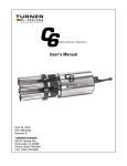
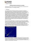
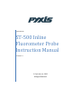
Pyxis Lab Inc. ST-500 Inline Fluorometer Probe Instruction Manual Version 1.3 Pyxis Lab, Inc. 2013 All Rights Reserved Contents 1. INTRODUCTION ............................................................................................................................................. 3 1.1. 2. ST-500 SERIES .................................................................................................................................................3 UNPACKAGING THE INSTRUMENT ................................................................................................................. 4 2.1. 2.2. STANDARD ACCESSORIES ....................................................................................................................................4 OPTIONAL ACCESSORIES .....................................................................................................................................4 3. SPECIFICATION .............................................................................................................................................. 4 4. INSTALLATION ............................................................................................................................................... 5 4.1. QUICK-START ...................................................................................................................................................5 4.1.1. Connect to a controller ........................................................................................................................5 4.1.2. Connect Solution Ground .....................................................................................................................6 4.2. CONNECTION TO A COMPUTER AND OTHER DEVICES................................................................................................7 4.2.1. Connect to a computer ........................................................................................................................7 4.2.2. Connect to Pyxis DC-200 Graphic Panel...............................................................................................7 5. PROBE CALIBRATION ..................................................................................................................................... 8 5.1. DOWNLOAD AND INSTALL PROBE CONFIGURATOR ...................................................................................................8 5.2. CALIBRATION VIA PROBE CONFIGURATOR ..............................................................................................................8 5.2.1. Zero Point Calibration ..........................................................................................................................9 5.2.2. Slope Calibration .................................................................................................................................9 5.2.3. 4-20 mA Output Setup .......................................................................................................................10 5.3. CALIBRATION ON THE CONTROLLER.....................................................................................................................10 5.4. CALIBRATION VIA PYXIS DC-200 PANEL ..............................................................................................................11 6. ADVANCED FUNCTIONS (ST-500B) ............................................................................................................... 11 6.1. 6.2. 7. MAINTENANCE AND TROUBLESHOOTING ................................................................................................... 11 7.1. 7.2. 7.3. 8. DOWNLOAD SAVED DATA .................................................................................................................................11 MODBUS TRU ...............................................................................................................................................11 GENERAL MAINTENANCE ..................................................................................................................................11 DOWNLOAD DIAGNOSIS PARAMETER FILE ............................................................................................................12 CLEAN ERRORS AND WARNINGS (ST-500B ONLY) ................................................................................................12 FIRMWARE UPGRADE .................................................................................................................................. 13 2 1. Introduction The Pyxis ST-500 inline fluorometer probe measures the concentration of fluorescence tracer PTSA (pyrenetetrasulfonic acid) in water. It can be simply inserted to the compression fitting port of a custom made tee. The companion tee has two ¾ inch female NPT ports and can be placed to an existing ¾ inch sample water line. The 4-20mA current output of the ST-500 probe can be connected to any controller that accepts an isolated or non-isolated 4-20mA input. The ST-500 probe is a smart device. In addition to measuring fluorescence, the ST-500 probe has extra photo-electric components that monitor the color and turbidity of the sample water. This extra feature allows automatic color and turbidity compensation to eliminate interferences common in real-world samples. The Pyxis ST-500 probe has a short fluidic channel. It can be easily cleaned. The fluidic and optical arrangement of the ST-500 probe is designed to overcome shortcomings associated with other fluorometers that have a distal sensor surface or a long, narrow fluidic cell. These fluorometers are susceptible to color and turbidity interference and fouling, and difficult to be cleaned. The Pyxis ST-500 probe uses a narrow wavelength band gallium phosphide photodiode and high temperature-tolerant and humidity-resistant optical filters. This combination greatly enhances the robustness of the probe. It can be operated under a wide range of ambient conditions without the need of humidity and temperature regulation. The performance of the ST-500 probe can be stable and consistent for a long period time. Other features of the ST-500 probe include: Menu-driven calibration procedure via a computer USB port. Any standard containing PTSA in the range of 40 to 200 ppb can be used for the calibration. The standard could be the water sample itself if the PTSA concentration of the sample is measured by an offline fluorometer. This allows the ST-500 probe to be calibrated online without being removed from the system. Automatic compensation for turbidity up to 150 NTU and color created by up to 10 ppm iron or equivalent to 10 ppm humic acid. The probe can be configured to an ultra sensitive mode, allowing PTSA monitoring at the 0 to 10 ppb range. Diagnostic information (probe fouling, color or turbidity over range, failure modes) are available via Modbus RTU (ST-500B). 30 day history data are stored in the probe and can be downloaded as a csv file to a PC via a UBS connection (ST-500B). The ST-500 probe can be easily removed from the system without the need of any tools for being cleaned. 1.1. ST-500 Series 3 Model ST-500 ST-500B ST-500C Output and Main Features 4-20 mA current output, Modbus RTU via RS485, calibration via PC interface Data saving in the probe, saved data, error and warning messages downloadable via Modbus 4 digital inputs and 4 digital outputs Availability Available Firmware upgrade via a computer interface Send requests to [email protected] 2. Unpackaging the Instrument Remove the instrument and accessories from the shipping container and inspect each item for any damage that may have occurred during shipping. Verify that all accessory items are included. If any item is missing or damaged, please contact Pyxis Lab Customer Service at [email protected]. 2.1. Standard Accessories 2.2. Tee Set (tee, O-ring, and nut) Bulkhead Cable Instrument Manual, also available from www.pyxis-lab.com Optional Accessories USB-RS485 Adapter (Item Number: MA-485) Pyxis Graphic Panel (Item Number: DC-200) 100 ppb PTSA Calibration Standard Solutions (Item Number: FCS-100) 200 ppb PTSA Calibration Standard Solutions (Item Number: FCS-200) 1.5 inch OD O-ring (Item Number: MA – 150) 3. Specification Power: 22 – 26 VDC Output: 4-20 mA and RS-485 Modbus RTU Temperature, Sample Water: 40 – 104 °F (4 – 40 °C) Temperature, Operation: 40 – 120 °F (4 – 49 °C) Temperature, Storage: 20 – 140 °F(-7 – 60 °C) Sample Pressure: up to 100 PSI Sample Flow Rate: 0 to 8 GPM 4 Cable Length: 5 feet, terminated with IP67 connectors Power consumption: 52 mA at 24 V Dimension: Length 6.8 inch (172.7 mm), body diameter 1.44 inch (36.6 mm) Weight: 0.46 pounds (210 grams) PTSA Range: 0 to 300 ppb (uncertainty ±1 ppb or 5% whichever is greater, 3 sigma) 4. Installation The ST-500 probe comes with a custom made tee. It is recommended that the tee is inserted to a pipe system to allow sample water to flow upwards vertically. Place the O-ring to the probe and insert the probe into the tee. Make sure that the fluidic channel in the probe is aligned with the sample flow direction. Please avoid over tightening the nut and the pipe when connecting the pipe to the tee. The ST-500 probe requires a solution ground. Solution ground connection is usually available inside water treatment controllers. If the solution ground connection is not available, insert a brass pipe when connect the tee to the sample flow system (Figure 1). The solution ground wire of the probe could be attached to the brass pipe. Figure 1. The ST-500 probe and the companion tee 4.1. Quick-Start 4.1.1. Connect to a controller 5 Follow the wiring table below to connect the ST-500 probe to a controller. The ST-500 probe is a three-wire, non-loop powered, 4-20mA device. It needs to be connected a 24 VDC power supplier. The negative 24V power wire (common) and the negative 4-20 mA wire (return) in the ST-500 probe are internally connected. The ST-500 probe 4-20mA output can be connected to an isolated or non-isolated 4-20mA input terminal in common water treatment controllers. The wiring designation, instruction, and principle are quite different from controller to controller. Please read the controller’s 4-20mA input wiring instruction carefully. Please note that the ST500 probe is a non-loop powered device. If a separate DC power supplier other than that from the controller is used, make sure that the output from the power supplier is within 22 to 26 VDC. Use a wire nut to terminate any wires that are not connected to the controller terminals. Wire Color Designation Red Black Brown or White Green Blue Yellow Clear 24 V + 24 V 4-20 mA + (output) 4-20 mA – (common), internally connected to 24 V – (power ground) RS-485 A RS-485 B Shield, solution ground 4.1.2. Connect Solution Ground If the solution ground connection is not available inside the controller, fix a solution ground wire to a brass pipe using a tubing clamp. Use the wire nut to connect the solution ground wire to the solution ground wire in the probe cable (clear wire). Figure 2. Connect the solution ground wire to a copper tube. 6 Do not connect the solution ground to the power ground! 4.2. Connection to a Computer and Other Devices 4.2.1. Connect to a computer Figure 3 shows the connection between a computer and the ST-500 probe via USB-RS485 adapter. Use the USB-RS485 adapter provided by Pyxis Lab Inc. (Item Number: MA-485). Insert the adapter between the two cable terminals. The controller side cable must be connected to the controller to provide power to the probe. Using other USB-485 adapters may result in instable connection and even permanent damage of the ST-500 probe communication hardware. Figure 3. Insert the USB adapter between the cable terminals. 4.2.2. Connect to Pyxis DC-200 Graphic Panel Pyxis DC-200 graphic panel (Item Number: DC-200) can be connected to the ST-500 series probes. The panel has a 4.3 inch, color touch screen. It displays the ST-500 probe ppb value in a graphic chart. The graphic interface allows the zero and slope calibration procedures to be carried out (section 7). 7 Figure 4. Connect to DC-200 graphic panel The DC-200 graphic panel can be powered by a separate 24 VDC power supplier or by the 24 VDC from the controller. The 4-20 mA output of the panel is proportional to the PTSA concentration and can be connected to the controller isolated or non-isolated current input port. 5. Probe Calibration 5.1. Download and Install Probe Configurator Download the Probe Configurator software package from www.pyxis-lab.com/download. Double click Probe Configurator Setup.msi file to install. The Probe Configurator icon will be placed on the computer desktop. 5.2. Calibration via Probe Configurator The probe is calibrated before shipping. It outputs 4 mA for zero ppb PTSA, 12 mA for 100 ppb PTSA, and 20 mA for 200 ppb. The probe can be recalibrated using the Probe Configurator Software. Connect the probe to a Windows computer using the USB-RS485 adapter provided by Pyxis Lab, Inc. It may a few minutes for the computer to automatically install the driver for the USB-RS485 adapter when being connected for the first time. If the driver for the adapter is not installed automatically, please download the drive from www.pyxis-lab.com/download and manually install the downloaded driver. 8 Double click the Probe Configurator icon to launch the program. If the probe is connected to the computer properly, the Probe Configurator software will detect the com port number and set up the communication parameters automatically. Click Connect button to connect the program to the probe. If the connection is successful, the probe system parameters will be filled as shown in figure 5. 5.2.1. Zero Point Calibration Put the probe into deionized water. Click the Zero Cal button to carry out the zero point calibration. If calibration is successful, the Calibration Successful message will be prompted. 5.2.2. Slope Calibration Put the probe into a solution with known PTSA concentration. Click the Slope Cal button to carry out the slope calibration. The PTSA concentration in the calibration solution should be in the range of 40 to 200 ppb. If calibration is successful, the Calibration Successful message will be prompted. If errors are determined, an error message indicating the cause of the errors will be shown. The zero point calibration and slope calibration can be carried out separately. It is recommended that the slope calibration be carried out after the zero point calibration. Figure 5. Probe Configurator connected Direct sunlight or indoor light on the probe should be avoided although it is not necessary to completely shield the probe from the ambient light during both the zero point and slope calibrations. 9 The calibration solution could be the sample water itself. The concentration of PTSA in the sample water can be determined with using an offline fluorometer like Pyxis SP-900, or calculated from the concentration of any species in the sample water such as polymer, phosphate, or molybdate. The Probe Configurator displays the real-time PTSA concentration when the AutoRefresh button is checked. The real-time PTSA is plotted in the Measurement Chart page. Figure 6. Real-time PTSA display. 5.2.3. 4-20 mA Output Setup The default setup is 20 mA output at 200 ppb PTSA. Fill in a value between 20 and 300 ppb and click the mA2ppb button to reset the 4-20 mA output range. If this range is reset to 100 ppb, the probe will output 20 mA at 100 ppb, 12 mA at 50 ppb, and 4 mA at 0 ppb. 5.3. Calibration on the Controller If the probe is set to output 20 mA at 200 ppb, the controller should be set up to convert 20 mA to 200 ppb and 4 mA to 0 ppb correspondingly. Optionally, the probe can be calibrated by changing the conversion factor on the controller without being undergone the zero point and slope calibration steps. For example, if the probe outputs 10 mA in a 120 ppb standard solution, calculate this value (z) according to: z = (120 ppb 20 mA)/(10 mA – 4 mA) = 400 ppb. 10 Fill in the z value 400 for 20 mA output in the controller’s mA-to-value conversion setup. This will force the controller to show 120 ppb when the probe is immersed in a 120 ppb solution. The advantage of this calibration is quick. The PTSA ppb concentration in the water sample can be determined by using an offline fluorometer or other methods such as the treatment product concentration. One can force the controller to show the determined PTSA concentration without the need to calibrate the probe using a standard solution. The disadvantage is that this method is only valid in a small range of PTSA concentration. Potential probe operation problems may not be able identified as they would in the zero and slope calibration procedures. 5.4. Calibration via Pyxis DC-200 Panel The zero point and slope calibration procedures are the same as described in section 5.2.1 to 5.2.3. 6. Advanced Functions (ST-500B) 6.1. Download Saved Data Connect the probe to the computer and launch the Probe Configurator. Click the download tap to start downloading the last 1000 measured PTSA ppb values to a CSV file. The PTSA value is saved every 60 seconds. Other critical probe operation parameters including errors and warnings are also downloaded to the same csv file. 6.2. Modbus RTU The ST-500B probe is a Modbus slave device. In addition to the ppb PTSA value, a range of operational parameters including warning and error message are available via Modbus TRU connection. Contact Pyxis Lab Customer Service ([email protected]) for more information. 7. Maintenance and Troubleshooting 7.1. General Maintenance The flow channel of the probe should be cleaned once a month using a soft brush. Deposit and debris should be removed. The probe can be cleaned with mild acid solution such as 1% citric acid. Do not use organic solvents or strong acid/base to clean the probe. 11 If the probe output signal is not stable and fluctuates significantly, check and make sure the solution ground is properly connected. Carry out routine calibration check against a PTSA standard. If necessary, carry out the zero point and slope calibration. Avoid long term storage at temperature over 100 °F. In an outdoor installation, properly shield the probe from direct sunlight and precipitation. 7.2. Download Diagnosis Parameter File Click on File -> Parameter Import to download the diagnosis parameter file. The file contains complete information needed for an accurate diagnosis of any probe operation problems and errors. Send this file to [email protected] if you need help to troubleshoot the probe. 7.3. Clean Errors and Warnings (ST-500B only) Connect the probe to a computer and open the error/warning log page in the Probe Configurator. If the probe is correctly operated under an error or warning condition, the error or/and warning message will be listed. The following table lists all error and warning messages and the procedure to resolve the associated problems. Item Sensor Error Flow Channel Fouling Warning High Turbidity Warning Low Temperature Warning High Temperature Description A fatal sensor error is determined. Possible causes including gross fouling on the probe flow channel and failure of optical components. Significant excitation light loss (>80%) is determined. Possible causes including gross fouling on the probe flow channel or the sample is intensively colored or turbid. Sample turbidity is too high (> 50 NTU) Less than 40 °F sample temperature is determined Procedure to Resolve Clean the probe with mild acid and remove all deposit and debris using a soft brush. Carry out the zero point calibration. If the error persists, contact Pyxis Lab Customer Service via email ([email protected]) Clean the probe with mild acid and remove all deposit and debris using a soft brush. If the warning persists, the warning is due to the sample color or turbidity. In this situation, the probe is still functioning properly and the result may not be accurate. The probe is still functioning properly. Carry out the controller calibration (6.3) after determining the PTSA concentration in the filtered sample using an offline fluorometer or other non-flurorescence methods. Non-specified operation temperature condition Greater than 120 °F sample temperature is determined Non-specified operation temperature condition 12 Warning 8. Firmware Upgrade The ST-500 probe can be upgrade to ST-500B via firmware upgrade. ST-500B stores 1000 last measured data points, downloadable to a csv file via the Probe Configurator software. Connect the probe to the computer and launch the Probe Configurator software. Locate the firmware file (.json) and start the download. . It normally takes around one minute to finish the update. In case there is a failure during the update process, try the process again. Contact Pyxis service for help if this process fails repeatedly. Pyxis Lab, Inc. PO Box 802 Hopkinton, MA 01748 USA www.pyxis-lab.com [email protected] 13