1
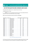
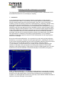
Calibrating the SCUFA for Chlorophyll in-vivo sampling
The following procedure provides a convenient and repeatable method to calibrate the SCUFA
submersible fluorometer for in-vivo chlorophyll a sampling.
1. Introduction
In vivo chlorophyll analysis is the fluorescent detection of chlorophyll a in living algal and
cyanobacterial cells in water. In this technique, the excitation light from the fluorometer passes
through untreated sample water and excites chlorophyll a within the cells. Environmental
conditions, presence of interfering compounds, cellular physiology, morphology, and light history
all can influence the relationship between in vivo fluorescence and the concentration of
chlorophyll a. Therefore, in vivo fluorescence is a semi-quantitative tool. Examples of interfering
materials include other algal pigments and their degradation products, dissolved organic matter,
and turbidity. Despite its semi-quantitative nature, in vivo fluorescence data supplies information
on the relative distribution of chlorophyll concentrations and can be collected quickly and easily.
To obtain quantitative data, the in vivo fluorescence data must be correlated with extracted
chlorophyll a data that can be obtained through the extraction and measurement of the pigment
from grab samples on a laboratory fluorometer or spectrophotometer. For more detailed
information of chlorophyll extractions and the EPA 445 method please visit the Algal Pigments
section of our web page.
Due to the conditions described above, it is not practical to try and obtain a primary calibration
standard for in vivo analysis. Therefore, the most logical approach for ‘calibrating’ the SCUFA is
to use the Solid Secondary Standard that will provide a repeatable calibration reference point and
allow the user to set the SCUFA’s sensitivity to a level similar to the field conditions.
A ‘post calibration’ is conducted after the in vivo data has been collected by performing the
extraction of chlorophyll a from grab samples and reading these samples on a fluorometer
equipped to read extracted samples. These results are used to correlate against the in vivo data
to provide a more accurate estimation of the actual chlorophyll a concentration (see graph 1).
Graph 1: Measured chlorophyll (in vivo chlorophyll) plotted against the corresponding calculated
chlorophyll, extracted chlorophyll a. A relationship or calibration factor is developed by comparing
the data from the grab samples taken. Once the factor is determined it can be applied to the
complete in vivo chlorophyll data set taken on a given day to ‘post calibrate’ the data and obtain a
estimate of the actual chlorophyll a concentration.
Table 1 gives estimated chlorophyll a levels based on correlation studies using algal cultures
grown in a lab environment. All SCUFA fluorometers are configured at the factory using a solid
standard to simulate the in vivo fluorescence of a 10 µg/L marine diatom culture.
See the User manual, section A3 for further details on the factory default settings.
Environment
Marine
Freshwater
Table 1
Std % value with
Chlor a level
(Cal. Standard value) Solid standard
10 ug/L
1%
30 ug/L
1%
These suggested calibration values should be viewed as a “ballpark” estimate of actual
chlorophyll concentration and you should expect that a natural assemblage of algae will have a
different in vivo fluorescence / chlorophyll a concentration relationship. You can read more about
algae and chlorophyll fluorescence on our web site.
When you calibrate the SCUFA as described below, you are assigning a value (Cal Standard
Value) to the fluorescent intensity of that standard. The Cal Standard Value you assign will be a
‘ball park’ estimate of the actual chlorophyll concentration.
The SCUFA calibration also provides the option to read a Blank solution and have it automatically
subtracted from the sample readings (zero point). This is not a necessary step since the in vivo
readings are semi-quantitative. However, if you choose to subtract a blank, the best blank is
natural water that has been filtered through a GF/F or membrane filter in order to remove the
algal cells but to retain the dissolved components.
For work in offshore marine environments where you expect a consistent background reading,
the blanking capability may allow improved resolution at low concentrations. The procedure below
skips the blanking step in order to utilize the SCUFA's absolute zero level . For more details,
refer to section 3.5.3 of the User Manual.
2. Equipment required
A) SCUFA submersible fluorometer configured for chlorophyll
B) The Solid Secondary Standard (PN 2000-901)
C) PC compatible computer with an available serial port.
D) The SCUFAsoft Interface Software installed on the computer.
E) SCUFA interface cable to provide power to the SCUFA and the serial output to the PC.
3. Procedure
A) Connect the SCUFA to the PC with the interface cable and power up the unit.
B) Start the SCUFAsoft software and verify you have communication. If you have a problem
establishing a connection, then see Appendix E of the User Manual to resolve any
communication issues.
C) If you have the Temperature Compensation option, then select the Temp. Compensation
button on the top toolbar and select Chlorophyll from the Application pull down list.
Select the Apply button to accept this setting and then close.
D) Select the Calibration button on the top toolbar and select Fluorescence from the channel pull
down list. Click on the Next button.
E) Enter the appropriate Calibration Standard Value from Table 1 above or a value that suites
you specific application.
F) At Step 3 of the Calibration Wizard, Blanking, click on the box to uncheck it and select Next.
This results in using the SCUFA’s absolute zero setting. This will prevent the possibility of
obtaining negative numbers.
Note: If you prefer to zero on a true blank solution you may do so by checking the box,
placing the SCUFA in the blank solution and selecting the Blank button.
Otherwise, proceed to Step 4 of the Calibration Wizard and step G below.
G) Place the Solid Secondary standard onto the detector end of the SCUFA. Be careful to install
correctly by aligning the temperature probe on the SCUFA with the recess on the underside
of the solid standard.
H) You should see the value change at the Standard % display.
I) Adjust the solid standard with a small screwdriver inserted in the center hole to obtain a
Standard % value equal to 1.0 or a different value of your choosing.
J) Click on the Calibrate button, allow the 15 second averaging to complete and select Next.
K) The calibration settings will be stored in the SCUFA, then select Next.
L) Select Yes for the secondary standard and click on the Record button.
M) Allow the 15-second averaging to complete and select Finish.
N) These calibration values are stored on the computer and can be viewed under Help >
Diagnostics.
O) If you have the Turbidity Channel option, use an appropriate turbidity standard solution and
perform the calibration. Refer to section C3 of the User Manual for specific details on
theTurbidity Channel.
Note – A Standard % reading of 1 % typically puts the Solid standard with less than 1/3 of the
small fluorescent rod showing up in the opening of the Solid Standard. We recommend that once
you set the position of your Solid Standard, that you leave it in that position, so you have a
constant reference to use over time. Keep the standard in a clean and dry location.
4. Analog output calibration scaling
If you plan to use the SCUFA’s 0 to 5 Volt analog output for external data collection, first verify
the SCUFA’s analog output settings. The 5 Volt setting should be set to a value slightly greater
than the maximum chlorophyll reading you expect to encounter. Also, verify the “input voltage
level” the external datalogger can accept. Some dataloggers cannot read a 5 volt level. You need
to consider this limit when deciding on the value to set in the SCUFA. For example, if the external
datalogger can only read up to 2.5 volts and you want the capability to Log the SCUFA readings
up to a value of 100, you need to set the SCUFA analog output so that 5 volts equals 200. See
section 3.7 of the User Manual for details.