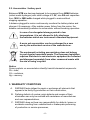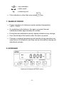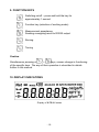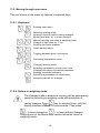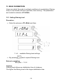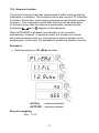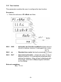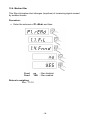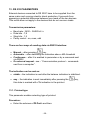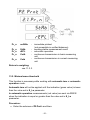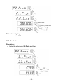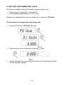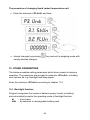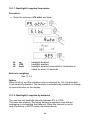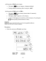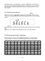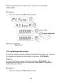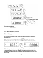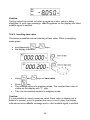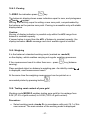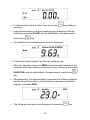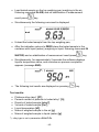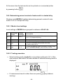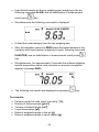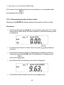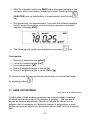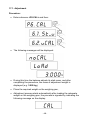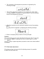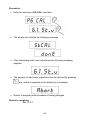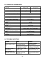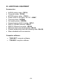
1
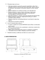
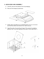
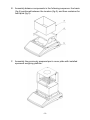
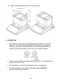
User Manual
Metal Purity Tester WTB/AU
User manual no.:
ITKU-78-04-09-12-A
MANUFACTURER OF ELECTRONIC
WEIGHING INSTRUMENTS
RADWAG Balances and Scales
26 – 600 Radom - Bracka 28 - POLAND
Phone +48 48 384 88 00, fax. +48 48 385 00 10
e-mail: [email protected]
www.radwag.com
SEPTEMBER 2012
-2-
TABLE OF CONTENTS
1. INTENDET USE..................................................................................................................... 5
2. PRECAUTIONS..................................................................................................................... 5
2.1. Maintenance .................................................................................................................. 5
2.2. Accumulator / battery pack ............................................................................................ 6
3. WARRANTY CONDITIONS................................................................................................... 6
4. MAIN DIMENSIONS .............................................................................................................. 7
5. UNPACKING AND ASSEMBLY............................................................................................ 8
6. START-UP........................................................................................................................... 10
7. WARM UP PERIOD............................................................................................................. 11
8. KEYBOARD ........................................................................................................................ 11
9. FUNCTION KEYS................................................................................................................ 12
10. DISPLAY INDICATIONS ................................................................................................... 12
11. USER MENU ..................................................................................................................... 13
11.1. Submenus................................................................................................................. 13
11.2. Moving through user menu ....................................................................................... 15
11.2.1. Keyboard ......................................................................................................... 15
11.2.2. Return to weighing mode ................................................................................ 15
12. MAIN PARAMETERS ........................................................................................................ 16
12.1. Setting filtering level.................................................................................................. 16
12.2. Autozero function ...................................................................................................... 17
12.3. Tare function ............................................................................................................. 18
12.4. Median filter .............................................................................................................. 19
13. RS 232 PARAMETERS ..................................................................................................... 20
13.1. Printout type.............................................................................................................. 20
13.2. Minimal mass threshold ............................................................................................ 21
13.3. Baud rate .................................................................................................................. 22
13.4. Serial transmission parameters ................................................................................ 23
14. SETTING SUPPLEMENTARY UNITS............................................................................... 24
15. OTHER PARAMETERS .................................................................................................... 25
15.1. Backlight function...................................................................................................... 25
15.1.1. Backlight if supplied from mains ...................................................................... 26
15.1.2. Backlight if supplied by batteries ..................................................................... 26
15.2. “Beep” signal – balance reaction for pressing a function key ................................... 27
15.3. Automatic switch-off.................................................................................................. 28
15.4. Battery voltage level check ....................................................................................... 29
15.4.1. Checking the batteries..................................................................................... 29
15.4.2. Battery discharge pictogram............................................................................ 30
15.4.3. Accumulator charging option ........................................................................... 30
15.4.4. Formatting rechargeable battery pack............................................................. 32
16. WORKING MODES ........................................................................................................... 32
16.1. Working mode selection............................................................................................ 33
16.2. Declaring liquid (water) temperature ......................................................................... 33
16.3. Declaring density of liquid ......................................................................................... 34
16.4. Basic weighing process ............................................................................................ 35
16.4.1. Tarring ............................................................................................................. 35
16.4.2. Inserting tare value .......................................................................................... 36
16.4.3. Zeroing ............................................................................................................ 37
-3-
16.5. Weighing ................................................................................................................... 37
16.6. Testing carat content of pure gold ............................................................................ 37
16.7. Testing carat content of gold alloy ............................................................................ 39
16.7.1. Mode’s local settings ....................................................................................... 39
16.7.2. Table of gold alloy density............................................................................... 39
16.7.3. Testing procedure ........................................................................................... 40
16.8. Testing platinum class .............................................................................................. 41
16.8.1. Mode’s local settings ....................................................................................... 42
16.8.2. Table of platinum alloy density ........................................................................ 42
16.8.3. Testing procedure ........................................................................................... 42
16.9. Determining percent content of main metal in a tested alloy .................................... 44
16.9.1. Mode’s local settings ....................................................................................... 44
16.9.2. Testing procedure ........................................................................................... 44
16.10. Determining density of other metals ........................................................................ 46
17. USER ADJUSTMENT ....................................................................................................... 47
17.1. Adjustment ................................................................................................................ 48
17.2. Start mass adjustment .............................................................................................. 49
18. COOPERATION WITH PRINTER ..................................................................................... 51
19. COOPERATION WITH COMPUTER................................................................................. 52
20. COOPERATION WITH TEMPERATURE SENSOR.......................................................... 53
21. COMMUNICATION PROTOCOL ...................................................................................... 53
21.1. General information .................................................................................................. 53
21.2. A set of commands for RS interfaces ....................................................................... 54
21.3. Responses format for commands sent from computer level..................................... 54
21.4. Command’s description ............................................................................................ 55
21.4.1. Zero balance ................................................................................................... 55
21.4.2. Tare balance ................................................................................................... 55
21.4.3. Give tare value ................................................................................................ 56
21.4.4. Send stable measurement result in basic measuring unit............................... 56
21.4.5. Immediately send measurement result in basic measuring unit...................... 57
21.4.6. Send stable measurement result in current weighing unit............................... 57
21.4.7. Immediately send measurement result in current measuring unit................... 58
21.4.8. Switch on continuous transmission in basic measuring unit ........................... 58
21.4.9. Switch off continuous transmission in basic measuring unit ........................... 59
21.4.10. Switch on continuous transmission in current measuring unit ...................... 59
21.4.11. Switch off continuous transmission in current measuring unit ...................... 59
21.4.12. Send all implemented commands................................................................. 60
21.5. Manual printouts / automatic printouts ...................................................................... 60
21.6. Continuous transmission........................................................................................... 61
22. ERROR MESSAGES......................................................................................................... 62
23. TECHNICAL PARAMETERS ............................................................................................ 63
24. TROUBLE SHOOTING ..................................................................................................... 63
25. ADDITIONAL EQUIPMENT............................................................................................... 64
-4-
1. INTENDET USE
Laboratory balances WTB/AU series, featuring special design of the
container and dedicated software, allow for density determination of
metals. Application of the density determining method provides the
following options:
• Determination of carat value of gold,
• Density determination of platinum,
• Density determination of other metals.
The software enables distinguishing precious metals from counterfeited by
density determination of a sample.
The standard design of the balances, includes temperature sensor TB-1,
which is used for temperature measurement of the liquid.
Additional functions:
•
•
•
•
•
•
•
•
•
•
•
•
•
Measuring units: [g], [oz],
Supplementary units: [K], [cm3], [g/cm3], [oz/gal], [°C], [°F], [%],
autozero function,
setting baud rate,
continuous data transmission for RS 232,
automatic operation for RS 232,
designating minimum mass for function operation,
automatic tare,
memory of tare,
manual inserting of tare value,
automatic scale switch-off,
user adjustment,
display backlight.
2. PRECAUTIONS
2.1. Maintenance
A. Before first use of the balance, it is highly recommended to carefully
read this User Manual, and operate the balance as intended.
B. Balances to be decommissioned, should be decommissioned
in accordance to valid legal regulations.
-5-
2.2. Accumulator / battery pack
Balances WTB are devices designed to be powered from NiMH batteries
(nickel-metal-hydrogen) with rated voltage of 1.2V, size R6 and capacities
from 1800 to 2800 mAh charged while plugged to mains without
stopping operation.
A balance plugged to mains continuously monitors the battery status and
charges it if necessary. After sudden power failure from the mains, the
balance automatically switches to accumulator without breaking operation.
In case of an elongated storage period in low
temperatures, it is not allowed to fully discharge
the batteries which are instrument’s standard equipment.
A worn out accumulator can be exchanged to a new
one by the authorized service of the manufacturer.
The equipment including accumulators does not belong
to your regular household waste. The European legislation
requires that electric and electronic equipment be collected
and disposed separately from other communal waste with
the aim of being recycled.
Notice:
Some symbols on accumulators identify harmful elements/compounds:
Pb = lead,
Cd = cadmium,
Hg = mercury.
3. WARRANTY CONDITIONS
A.
RADWAG feels obliged to repair or exchange all elements that
appear to be faulty by production or their construction,
B. Defining defects of unclear origin defects and means of their
elimination can only be realized with assistance of manufacturer
and user representatives,
C. RADWAG does not bear any responsibility for defects, losses or
accidents resulting from unauthorized or inadequate performing
of production or service processes,
-6-
D. Warranty does not cover:
• Mechanical defects caused by product exploitation other than
intended, defects of thermal and chemical origin, defects caused
by lightning, overvoltage in the power network or other random
event,
• Balance defects if it is utilized contrary to its intended use,
• Balance defects, if service claims removing or destroying
product’s protective stickers which protect the balance’s
housing against unauthorized access.
• Mechanical defects or defects caused by liquids and natural wear,
• Balance defects caused by inappropriate setting of a defect
of electric power network,
• Defects caused by overloading balance’s mechanical measuring
system,
• Maintenance activities (cleaning).
E. Loss of warranty takes place if:
• A repair is carried out outside RADWAG sales office or authorized
service point,
• Service claims intrusion into mechanical or electronic construction
by unauthorized people,
• Other version of the operating system is installed in a balance,
• The balance does not bear company’s protective stickers.
F. Detailed warranty conditions are listed on a service card.
4. MAIN DIMENSIONS
Dimensions of balance WTB/AU series
-7-
5. UNPACKING AND ASSEMBLY
A. Carefully remove the balance from its packaging,
B. Remove the transport protections:
C. Gently place the balance in its intended place of use, on an even
and hard foundation and distant from heat sources,
D. Insert the ends of connecting strings of the openwork weighing
platform (fig. 2) into the openings of the pan’s cover plate (fig. 1):
-8-
E. Assembly balance components in the following sequence: the basis
(fig.4) positioned between the locators (fig.5), and then container for
test liquid (fig.3):
F. Assembly the previously prepared pan’s cover plate with installed
openwork weighing platform.
-9-
G. Install temperature sensor TB-1 of the liquid:
6. START-UP
• After balance unpacking and assembling, the balance has to be
leveled. Use balance’s adjustable feet and the level located on
balance’s overlay to level the balance. Screw adjustable feet in
a way to set the air bubble of the level in its central location.
• Switch on the balance by pressing the
the key for about 1 sec,
key – press and hold
• On switching on, wait until the balance test is completed,
• On test completion, the balance displays zero indication
and the following pictograms:
- 10 -
- zero indication
- stable result
kg
- measuring unit
• If the indication is other than zero press
key.
7. WARM UP PERIOD
• Proper operation of a balance requires ambient temperature
+15°C ÷ +30°C;
• On switching on the balance, the warm up period (thermal
stabilization) takes approximately 60 minutes;
• During thermal stabilization period, display indications may change;
• User should adjust the balance after the warm-up period.
• Changes in ambient temperature and humidity during operation can
cause errors of indications, and they can be removed by carrying out
adjustment process.
8. KEYBOARD
Keyboard of balance WTB/AU series
- 11 -
9. FUNCTION KEYS
Switching on/off – press and hold the key for
approximately 1 second
Function key (selection of working mode)
Measurement acceptance
Sending a weighing result to RS232 output
Zeroing
Tarring
Caution:
+
keys, causes change in functioning
Simultaneous pressing of
of the specific keys. The way of their operation is described in details
further in this manual.
10. DISPLAY INDICATIONS
Display of WTB/AU series
- 12 -
No
1.
Text string
Net
Description
Balance tarred
2.
Balance in autozero zone (indication = precise zero)
3.
Stable measurement result (result ready for reading)
4.
Negative (with minus sign) measurement result
5.
Battery indicator
6.
Indicator of active working mode
7.
Weighing status
8.
Weighing in the air
9.
Weighing in liquid (water)
10.
Process completed
11.
Measuring unit: density
12.
Measuring unit: density
13.
Gold caratage (Percent content of tested metal)
14.
Proportion of fine gold in an alloy
15.
Platinum class
16.
Liquid (water) temperature in [°C]
17.
Liquid (water) temperature in [°F]
18.
Last digit marker
11. USER MENU
11.1. Submenus
User’s menu is divided into 6 basic submenus. Each group has its own
characteristic name preceded by capital letter P and a number.
- 13 -
No
Parameter
name
Default
settings
P1
1.1
1.2
1.3
1.4
P2
2.1
2.2
2.3
2.4
P3
3.1
3.2
P4
4.1
4.2
4.3
rEAd
Fil
Auto
tArA
Fnnd
Prnt
Pr_n
S_Lo
bAud
S_rS
Unit
StUn
FLUn
Func
tnnP
dEnS
F-K
3
4.3.1
out
K-1
4.3.2
rtK
7:3
Copper and Silver % ratio
Testing platinum alloy – alloy selection
(P-1: platinum / nickel; P-2: platinum / palladium)
YES
no
YES
StAb
9600
8d1SnP
g
°C
-
Description
Mains parameters
Setting a filtering level
Control of balance’s zero indication
Enabling / Disabling tare function
Median filter
RS 232 parameters setting
Printout type
Minimal mass threshold
Baud rate
Serial transmission parameters
Supplementary unit settings
Change of measuring unit: [g] or [oz]
Change of liquid (water) temperature unit: [°C] or [°F]
Working modes
Declaring liquid (water) temperature in [°C]
3
Declaring solution density in [g/cm ]
Testing gold alloy
Selecting gold alloy (K-1: gold / copper / silver;
K-2: gold / copper; K-3: gold / silver)
4.4
F–P
P-1
4.5
F-A
-
Testing metal alloy
Selecting metal alloy (ALL-2: 2-component alloy;
ALL-3: 3-component alloy)
4.5.1
in
ALL-2
4.5.2
4.5.3
4.5.4
4.5.5
P5
5.1
5.2
5.3
5.4
5.5
P6
6.1
6.2
d1
d2
d3
rtA
othr
bL
bLbt
bEEP
t1
CHr6
CAL
St_u
uCAL
5:5
Auto
70
YES
Auto
YES
-
Density of the main metal in an alloy
Density of the subsidiary (secondary) metal in an alloy
Density of the subsidiary (third) metal in an alloy
% ratio of subsidiary metal in an alloy
Other parameters
Backlight function (power supply from mains)
Backlight function (power supply from batteries)
Beep sound on pressing keys
Power save – balance switch off if not operated
Battery charging mode
User adjustment
Determining start mass
Balance adjustment
- 14 -
11.2. Moving through user menu
The user moves in the menu by balance’s keyboard keys.
11.2.1. Keyboard
Entering main menu
+
+
Selecting working mode
Leaving a function without saving changes
Moving one level “up” in menu structure
Manual inserting tare value in weighing mode
Change of digit value by “1” up
Scrolling the menu upwards
Check battery status
+
Toggling between gross / net values
+
Previewing temperature value
+
Changing working mode
Selecting a parameter on one menu level
Changing the value of an active parameter
Entering a selected submenu
Activating a parameter for modification
Accepting carried out changes
11.2.2. Return to weighing mode
The changes made in balance’s memory will be permanently
saved on returning to weighing mode with procedure of
key for several times, until the
saving changes. Press
display indicates <SAuE?> communicate. Then press:
– to save changes or
– to leave without changes.
Pressing one of the above keys causes automatic return to
weighing mode.
- 15 -
12. MAIN PARAMETERS
Users can adjust the scale to ambient conditions at a workstation (filtering
level) or user needs (autozero operation, tare memory). The parameters
are located in submenu <P1.rEAd>.
12.1. Setting filtering level
Procedure:
• Enter the submenu <P1.rEAd> and then:
1 - 4 - available filtering level settings
• By pressing
select required filtering level.
Return to weighing:
See point – 11.2.2.
Caution:
Filtering level influences stabilization time of a balance.
The higher the filtering level is the longer stabilization time.
- 16 -
12.2. Autozero function
The autozero function has been implemented in order to assure precise
indications of a balance. This function controls and corrects “0” indication.
If enabled, the function continuously compares the results with constant
frequency. If two sequential results differ less than the declared value
of autozero range, then the balance is automatically zeroed and the
and
appear on the displayed.
pictograms
When AUTOZERO is disabled zero indication is not corrected
automatically. However, in particular cases, this function can disrupt
the measurement process e.g. slow pouring of liquid or powder on the
weighing pan. In this case, it is advisable to disable the autozero function.
Procedure:
• Enter the submenu <P1.rEAd> and then:
AUTOno
- autozero disabled
AUTOYES - autozero enabled
Return to weighing:
See - 11.2.2.
- 17 -
12.3. Tare function
This parameters enables the user to configure the tare function.
Procedure:
• Enter the submenu <P1.rEAd> and then:
tArA
AtAr
-
automatic tare function enabled and tare value is
stored in balance memory if unplugged from mains
tArA
no
-
Standard tare mode (tarring by pressing
tArA
tArF
-
tare memory function – stores last value of tare in
balance memory. It is automatically displayed after
starting the balance. Value of tare is displayed with
minus sign, and there is Net pictogram indicated
on the display.
Return to weighing:
See - 11.2.2.
- 18 -
key);
12.4. Median filter
This filter eliminates short changes (impulses) of measuring signal caused
by sudden shocks.
Procedure:
• Enter the submenu <P1.rEAd> and then:
Fnnd
Fnnd
no
- filter disabled
YES - filter enabled
Return to weighing:
See - 11.2.2.
- 19 -
13. RS 232 PARAMETERS
External devices connected to RS 232C have to be supplied from the
same mains and common electric shock protection. It prevents from
appearing a potential difference between zero leads of the two devices.
This notice does not apply to the devices that do not use zero leads.
Transmission parameters:
•
•
•
•
Baud rate - 2400 ÷ 38400 bit / s
Data bits - 7,8
Stop bits - 1,2
Parity control - no, even, odd
There are four ways of sending data via RS232 interface:
key,
• Manual – after pressing
• Automatic – after stabilizing the indication above -LO- threshold
• Continuous – after it is enabled in parameter or by a command sent
via RS232
• On external request - see – “Communication protocol – commands
sent from a computer”.
The indication can be sent as:
• stable – the indication is sent after the balance indication is stabilized.
• any – the indication is sent immediately after pressing the
this state is marked with <?> indication in the printout.
13.1. Printout type
This parameter enables selecting type of printout.
Procedure:
• Enter the submenu <P2.Prnt> and then:
- 20 -
key,
Pr_n
noStAb
-
Pr_n
Pr_n
Pr_n
StAb
rEPL
CntA
-
Pr_n
Cntb
-
immediate printout
(not accessible in verified balances)
sending stable measurement result
automatic operation
continuous transmission in basic measuring
unit
continuous transmission in current measuring
unit
Return to weighing:
see 11.2.2.
13.2. Minimal mass threshold
This function is necessary while working with automatic tare or automatic
operation mode.
Automatic tare will not be applied until the indication (gross value) is lower
than the value set in S_Lo parameter.
In automatic operation measurements (net value) are sent via RS232
when the indication is equal or greater than the value set in S_Lo
parameter.
Procedure:
• Enter the submenu <P2.Prnt> and then:
- 21 -
Return to weighing:
see 11.2.2.
13.3. Baud rate
Procedure:
• Enter the submenu <P2.Prnt> and then:
- 22 -
Return to weighing:
see 11.2.2.
13.4. Serial transmission parameters
Procedure:
• Enter the submenu <P2.Prnt> and then:
7d2SnP
7d1SEP
7d1SoP
8d1SnP
8d2SnP
8d1SEP
8d1SoP
- 7 data bits; 2 stop bits, no parity control
- 7 data bits; 1 stop bit, EVEN parity control
- 7 data bits; 1 stop bit, ODD parity control
- 8 data bits; 1 stop bit, no parity control
- 8 data bits; 2 stop bits, no parity control
- 8 data bits; 1 stop bit, EVEN parity control
- 8 data bits; 1 stop bit, ODD parity control
Return to weighing:
See 11.2.2.
- 23 -
14. SETTING SUPPLEMENTARY UNITS
The balance enables setting the following supplementary units:
• Measuring unit: grams [g] or ounces [oz],
• Liquid (water) temperature unit: [°C] or [°F].
Changes of supplementary units are carried out in submenu <P3.Unit>.
The procedure of changing the measuring unit:
• Enter the submenu <P3.Unit> and then:
• Measuring units are changed by pressing
• Accept changes by pressing
saving inserted changes.
key:
key and exit to weighing mode with
- 24 -
The procedure of changing liquid (water) temperature unit:
• Enter the submenu <P3.Unit> and then:
• Accept changes by pressing
saving inserted changes.
key and exit to weighing mode with
15. OTHER PARAMETERS
The balance enables setting parameters which have impact on balance
operation. The parameter are grouped in submenu <P5.othr>, including
such options as: e.g. backlight and beep signal.
Enter the submenu <P5.othr> according to chapter 11.2.
15.1. Backlight function
Program recognizes the means of balance supply (mains or battery)
and automatically selects the operating mode of backlight function:
bl
blbt
– from mains
– by batteries or rechargeable battery pack
- 25 -
15.1.1. Backlight if supplied from mains
Procedure:
• Enter the submenu <P5.othr> and then:
bL
bL
bL
no
YES
Auto
-
backlight disabled
backlight enabled
backlight disabled automatically if indication is
stable for about 10 seconds
Return to weighing:
See 11.2.2.
Notice:
When bl=Auto, and the indication has not changed for 10s, the backlight
is automatically disabled. The backlight is automatically enabled on change
of mass indication on the display.
15.1.2. Backlight if supplied by batteries
The user can set backlight intensity between 0% to 100%.
The lower the intensity, the longer balance’s operation time without
recharging or exchanging the batteries. When the intensity is set to
zero it functions in AUTO mode (described above).
- 26 -
Procedure:
• Enter the submenu <P5.othr> and then:
Return to weighing:
See 11.2.2.
Notice:
The more intense the backlight, the shorter the balance operates on
batteries.
15.2. “Beep” signal – balance reaction for pressing a function key
Procedure:
• Enter the submenu <P5.othr> and then:
- 27 -
bEEP
bEEP
no
- disabled
YES - enabled
Return to weighing:
See 11.2.2.
15.3. Automatic switch-off
This function is essential for saving the battery power. The balance’s
display is switched off automatically if (function t1 = YES) no weighing
appears within 5 minutes. (the mass indication does not change on the
display). In case this function disrupts the operation (e.g. long lasting
weighing procedure) or while working with balance plugged to mains, the
function can be disabled.
Operation according to active power supply:
Setting
t1 = 0
t1 = YES
t1 = Auto *
Mains
disabled
enabled
disabled
Operation
Batteries/accumulator
disabled
enabled
enabled
* automatic enabling/disabling according to the source of power.
- 28 -
Procedure:
• Enter the submenu <P5.othr> and then:
Returnto weighing:
See 11.2.2.
15.4. Battery voltage level check
While supplying from batteries, the current voltage level is measured. Is the
appearing on the
voltage becomes too low, it is signaled by pictogram
display, and it denotes the need to charge the batteries / accumulators or
exchange the batteries..
15.4.1. Checking the batteries
This function enables checking the level of power supply from batteries.
The option is enabled if:
- 29 -
• Weighing mode is enabled;
• Battery supply is enabled in balance parameters.
Procedure:
After displaying the charge level of batteries (in percentage) the software
returns to weighing.
15.4.2. Battery discharge pictogram
The symbol (bat low) [battery low] switches on when the voltage level
decreases to 18% of the accepted voltage level. In such case change or
charge the batteries/accumulators.
Low level of batteries:
• Pictogram
is visible on the display,
• If the batteries are not exchanged / charged, the balance will switch off
automatically to protect against excessive batteries discharge,
• Charging is signaled by flickering pictogram
about 2 seconds) on the display.
(flickering interval is
15.4.3. Accumulator charging option
This function allows to switch to charging algorithm for NiMH batteries:
- 30 -
a) Parameter <CHr6> set to <no>:
• Pictogram
does not appear, charging disabled.
• During software initializing, after turning on „bAtt”.
b) Parameter <CHr6> set to <YES>:
•
Pictogram
flickers slowly (interval about 2 seconds),
charging is enabled.
•
Message „nImh” appears on the display,
•
In case of damaging accumulators or their absence, the pictogram
flickers quickly (interval about 0.5 sec).
Caution:
Balance comes standard with a set of rechargeable batteries
NiMH R6 (AA) and a power adapter.
Procedure:
• Enter the submenu <P5.othr> and then:
CHr6 YES
CHr6 no
- enabled
- disabled
- 31 -
Return to weighing:
See 11.2.2.
15.4.4. Formatting rechargeable battery pack
The indicator features a brand new battery pack comprising NiMH R6 (AA)
batteries and a power adapter. The batteries need formatting after first
powering up. It is crucial for batteries lifetime to undertake this process.
Formatting requires first full charging the batteries, followed by total
discharging (without meantime charging).
Procedure:
1.
2.
3.
4.
Supply the indicator from mains.
Charge batteries for 12 hours (charging time of 2200mAh batteries).
After 12 hours unplug from mains.
Use the device up to the moment of its automatic switch off due
to low battery level.
5. Repeat the process of charging starting from point 1.
Caution:
Batteries reach their optimal capacity after three cycles of full charging
and discharging.
16. WORKING MODES
Balance series WTB/AU feature the following working modes:
Symbol
B
G
K
P
A
S
Name
Weighing
Caratage (Testing carat content of pure gold)
Caratage (Testing carat content of gold alloy (gold with
admixture of silver / copper / silver and copper)
Testing platinum class (platinum with admixture
of nickel or admixture of palladium)
Determining percent content of main metal in a tested
alloy (2 or 3 component alloys)
Determining density of other metals
- 32 -
Working modes are configurable in submenu <P4.Func>, which feature
special functions enabling adjusting balance operation to user needs and
requirements. The above described modes are described further in this
user manual.
16.1. Working mode selection
While in the main window of the weighing mode press
key, which
displays a message <SELECt> and flickering pictogram of active working
mode:
Press
key to select required working mode and accept it by pressing
key. The software automatically returns to the main window.
16.2. Declaring liquid (water) temperature
Each working mode, except for mode B (Weighing), includes density
of liquid (water) in relation to declared temperature (see below table).
°C
0
10
20
30
40
50
60
70
80
90
+0
+1
+2
+3
+4
+5
+6
+7
+8
+9
0.99984 0.99990 0.99994 0.99996 0.99997 0.99996 0.99994 0.99990 0.99985 0.99978
0.99970 0.99961 0.99949 0.99938 0.99924 0.99910 0.99894 0.99877 0.99860 0.99841
0.99820 0.99799 0.99777 0.99754 0.99730 0.99704 0.99678 0.99651 0.99623 0.99594
0.99565 0.99534 0.99503 0.99470 0.99437 0.99403 0.99368 0.99333 0.99297 0.99259
0.99222 0.99183 0.99144 0.99104 0.99063 0.99021 0.98979 0.98936 0.98893 0.98849
0.98804 0.98758 0.98712 0.98665 0.98618 0.98570 0.98521 0.98471 0.98422 0.98371
0.98320 0.98268 0.98216 0.98163 0.98110 0.98055 0.98001 0.97946 0.97890 0.97834
0.97777 0.97720 0.97662 0.97603 0.97544 0.97485 0.97425 0.97364 0.97303 0.97242
0.97180 0.97117 0.97054 0.96991 0.96927 0.96862 0.96797 0.96731 0.96665 0.96600
0.96532 0.96465 0.96397 0.96328 0.96259 0.96190 0.96120 0.96050 0.95979 0.95906
- 33 -
Declaring liquid (water) temperature is carried out in parameter
<P4.1.tnnP>.
Procedure:
• Enter the submenu <P4.Func> and then:
Return to weighing:
See 11.2.2.
16.3. Declaring density of liquid
In case the testing procedure applies liquid other than water (e.g. glycerin),
it is possible to declare liquid’s density in submenu <P4.2.dEnS>.
Caution:
In case of declaring density of liquid in submenu <P4.2.dEnS>, the
temperature of water declared in parameter <P4.1.tnnP> is neglected
by the balance software.
Procedure:
• Enter the submenu <P4.Func> and then:
- 34 -
Return to weighing:
See 11.2.2.
16.4. Basic weighing process
16.4.1. Tarring
In order to determine the net mass load the packaging on balance’s
weighing pan.
key (Net pictogram is
After measurement stabilization press
displayed in the upper left corner and zero mass indication appears).
After placing a load on the weighing pan, the net mass is measured.
Tarring is possible within the balance’s whole measuring range. After
unloading the weighing pan, the display indicates total tarred value with
minus sign.
- 35 -
Caution:
Tarring cannot be carried out when a negative or zero value is being
displayed. In such case message <Err3> appears on the display and short
audible signal is emitted.
16.4.2. Inserting tare value
The balance enables manual inserting of tare value. While in weighing
mode press:
• simultaneously
and
• the display indicates:
keys,
•
Using
•
•
Press
key,
The software returns to weighing mode. The inserted tare value is
visible on the display with “–” sign,
Tare can be inserted anytime in weighing mode.
•
and
keys set tare value,
Caution:
It is not possible to insert a new tare value if tare value is already set in
balance’s memory and it is greater than zero. In such case, the display
indicates an error <Err3> message and a short audible signal is emitted.
- 36 -
16.4.3. Zeroing
To ZERO the indication press:
key.
The balance’s display shows mass indication equal to zero, and pictograms
and
appear.
Zeroing is an activity equal to setting a new zero point, comprehended by
the balance as the precise zero point. Zeroing is accessible only with stable
display status.
Caution:
Zeroing of display indication is possible only within the ±2% range from
balance’s maximal capacity.
If zeroed value is more than the ±2% of balance’s maximal capacity, the
display indicates <Err2> message and short audible signal is emitted.
16.5. Weighing
It is the balance’s standard working mode (marked as: mode B)
on the display, which enables carrying out regular weighing processes.
If the measurement result is other than zero – press
zeroing).
key (balance
Place weighed object on balance’s weighing pan. As stability marker
is displayed, read measurement result.
At the same time the weighing measurement can be printed on a
connected printer by pressing button
.
16.6. Testing carat content of pure gold
Working mode MODE G enables testing pure gold for its caratage from
9.0K (37.5% of gold content) to 24.0K (100% of gold content).
Procedure:
• Select working mode <mode G> in accordance with point 16.1 of this
user manual. The main window of the working mode is displayed:
- 37 -
• If measurement result is other than zero press
zeroing).
key (balance
• Load tested sample on the top weighing pan (weighing in the air,
flickering command IN AIR) and on stabilization of measurement
result press
key.
• Simultaneously the following command is displayed:
• Unload the tested sample from the top weighing pan,
• After the indication returns to ZERO place the tested sample in the
container with liquid (water) (weighing in liquid, flickering command
IN WATER) and on stabilization of measurement result press
key,
• Simultaneously, for approximately 2 seconds the software displays
liquid’s temperature value, and a window on process completion
appears (message END):
• The following test results are displayed on pressing
- 38 -
key.
Test results:
•
•
•
•
•
•
•
Gold caratage [K],
Percent content of gold in tested sample [%],
Density of tested sample [g/cm3],
Volume of tested sample [cm3],
Liquid temperature [°C],
Mass of weighed sample in the air [g],
Mass of weighed sample in liquid (water) [g].
At the same time the test results can be printed on a connected printer
by pressing button
.
16.7. Testing carat content of gold alloy
Working mode MODE K enables testing one of three gold alloys:
• Gold with admixture of silver and copper (mode K-1),
• Gold with admixture of copper (mode K-2),
• Gold with admixture of silver (mode K-3).
16.7.1. Mode’s local settings
Local settings of MODE K are grouped in submenu <P4.3.F-K>:
No.
Parameter
name
Default
settings
Description
4.3.1
out
K-1
Gold alloy selection (K-1: gold / copper / silver;
K-2: gold / copper; K-3: gold / silver)
4.3.2
rtK
7:3
% ratio of copper and silver (in K-1 alloy).
Available settings – 4:6, 5:5, 6:4, 7:3
16.7.2. Table of gold alloy density
The table contains the density values of subsidiary components in an alloy
with regards to gold caratage in a tested sample:
- 39 -
3
Density of metal alloy [g/cm ]
Gold
caratage
[K]
% content
24
22
20
18
14
10
100 / 100
91.6 / 100
83.4 / 100
75.0 / 100
58.4 / 100
41.7 / 100
Copper
and silver
Copper
Silver
19.32
17.73
16.42
15.24
13.38
11.91
19.32
17.63
16.19
14.99
13.04
11.54
19.32
18.06
16.94
15.96
14.30
12.96
Range of sample
3
density [g/cm ]
19.13 ~ 19.51
17.45 ~ 18.24
16.03 ~ 17.11
14.84 ~ 16.12
12.91 ~ 14.44
11.42 ~ 13.09
16.7.3. Testing procedure
• Select working mode <mode K> in accordance with point 16.1 of this
user manual, after which the main window of selected working mode is
displayed:
• If measurement result is other than zero press
zeroing).
key (balance
• Load tested sample on the top weighing pan (weighing in the air,
flickering command IN AIR) and on stabilization of measurement
result press
key,
• Simultaneously the following command is displayed:
• Unload the tested sample from the top weighing pan,
- 40 -
• After the indication returns to ZERO place the tested sample in the
container with liquid (water) (weighing in liquid, flickering command
IN WATER) and on stabilization of measurement result press
key,
• Simultaneously, for approximately 2 seconds the software displays
liquid’s temperature value, and a window on process completion
appears (message END):
• The following test results are displayed on pressing
key.
Test results:
•
•
•
•
•
•
•
Caratage of gold alloy* [K],
Percent content of gold in tested alloy* [%],
Density of tested sample [g/cm3],
Volume of tested sample [cm3],
Liquid temperature [°C],
Mass of weighed sample in the air [g],
Mass of weighed sample in liquid (water) [g].
*) – alloy type is set in parameter <P4.3.1.out>.
At the same time the test results can be printed on a connected printer
by pressing button
.
16.8. Testing platinum class
Working mode MODE P enables testing one of two platinum alloys:
• Platinum with admixture of nickel (mode P-1),
• Platinum with admixture of palladium (mode P-2).
- 41 -
16.8.1. Mode’s local settings
Local settings of MODE P are grouped in submenu <P4.4.F-P>:
No.
Parameter
name
Default
settings
Description
4.4
F–P
P-1
Testing platinum alloy – alloy selection
(P-1: platinum / nickel; P-2: platinum / palladium)
16.8.2. Table of platinum alloy density
The table contains the density values of subsidiary components in an alloy
with regards to platinum class in a tested sample:
3
Platinum
class [PT]
% content
1000
950
900
850
800
750
100 / 100
95.0 / 100
90.0 / 100
85.0 / 100
80.0 / 100
75.0 / 100
Density of metal alloy [g/cm ]
Nickel
Palladium
21.45
20.04
18.80
17.71
16.73
15.86
21.45
20.64
19.88
19.18
.18.53
17.92
Range of sample
3
density [g/cm ]
21.24 ~ 21.66
19.84 ~ 20.85
18.61 ~ 20.08
17.53 ~ 19.38
16.56 ~ 18.72
15.70 ~ 18.10
16.8.3. Testing procedure
• Select working mode <mode P> in accordance with point 16.1 of this
user manual, after which the main window of selected working mode is
displayed:
• If measurement result is other than zero press
zeroing).
- 42 -
key (balance
• Load tested sample on the top weighing pan (weighing in the air,
flickering command IN AIR) and on stabilization of measurement
result press
key,
• Simultaneously the following command is displayed:
• Unload the tested sample from the top weighing pan,
• After the indication returns to ZERO place the tested sample in the
container with liquid (water) (weighing in liquid, flickering command IN
WATER) and on stabilization of measurement result press
key,
• Simultaneously, for approximately 2 seconds the software displays
liquid’s temperature value, and a window on process completion
appears (message END):
• The following test results are displayed on pressing
Test results:
•
•
•
•
•
•
•
Platinum alloy class* [PT],
Percent content of platinum in tested alloy* [%],
Density of tested sample [g/cm3],
Volume of tested sample [cm3],
Liquid temperature [°C],
Mass of weighed sample in the air [g],
Mass of weighed sample in liquid (water) [g].
*) - alloy type is set in parameter <P4.4.F-P>.
- 43 -
key.
At the same time the test results can be printed on a connected printer
.
by pressing button
16.9. Determining percent content of main metal in a tested alloy
Working mode MODE A enables determining percent content of main
metal in a 2 or 3 component alloy.
16.9.1. Mode’s local settings
Local settings of MODE A are grouped in submenu <P4.5.F-A>:
No.
Parameter
name
Default
settings
Description
4.5.1
in
ALL-2
Metal alloy selection (ALL-2: 2-components alloy,
ALL-3: 3-components alloy)
4.5.2
4.5.3
d1
d2
-
Density of main metal in an alloy
Density of subsidiary (second) metal in an alloy
4.5.4
d3
-
Density of subsidiary (third) metal in an alloy.
In case of alloy ALL-3.
4.5.5
rtA
5:5
% ratio of subsidiary metals in an alloy. In case of alloy
ALL-3. Available settings – 4:6, 5:5, 6:4, 7:3, 8:2
16.9.2. Testing procedure
• Select working mode <mode A> in accordance with point 16.1 of this
user manual, after which the main window of selected working mode is
displayed:
• If measurement result is other than zero press
zeroing).
- 44 -
key (balance
• Load tested sample on the top weighing pan (weighing in the air,
flickering command IN AIR) and on stabilization of measurement
result press
key,
• Simultaneously the following command is displayed:
• Unload the tested sample from the top weighing pan,
• After the indication returns to ZERO place the tested sample in the
container with liquid (water) (weighing in liquid, flickering command
IN WATER) and on stabilization of measurement result press
key,
• Simultaneously, for approximately 2 seconds the software displays
liquid’s temperature value, and a window on process completion
appears (message END):
• The following test results are displayed on pressing
Test results:
•
•
•
•
•
•
Percent content of main metal in an alloy* [%],
Density of tested sample [g/cm3],
Volume of tested sample [cm3],
Liquid temperature [°C],
Mass of weighed sample in the air [g],
Mass of weighed sample in liquid (water) [g].
- 45 -
key.
*) - alloy type is set in parameter <P4.5.1.in>.
At the same time the test results can be printed on a connected printer
by pressing button
.
16.10. Determining density of other metals
Working mode MODE S enables determining density of other metals.
Procedure:
• Select working mode <mode S> in accordance with point 16.1 of this
user manual, after which the main window of selected working mode
is displayed:
• If measurement result is other than zero press
zeroing).
key (balance
• Load tested sample on the top weighing pan (weighing in the air,
flickering command IN AIR) and on stabilization of measurement
result press
key,
• Simultaneously the following command is displayed:
• Unload the tested sample from the top weighing pan,
- 46 -
• After the indication returns to ZERO place the tested sample in the
container with liquid (water) (weighing in liquid, flickering command
IN WATER) and on stabilization of measurement result press
key,
• Simultaneously, for approximately 2 seconds the software displays
liquid’s temperature value, and a window on process completion
appears (message END):
• The following test results are displayed on pressing
key.
Test results:
•
•
•
•
•
Density of tested sample [g/cm3],
Volume of tested sample [cm3],
Liquid temperature [°C],
Mass of weighed sample in the air [g],
Mass of weighed sample in liquid (water) [g].
At the same time the test results can be printed on a connected printer
by pressing button
.
17. USER ADJUSTMENT
Only for non-verified scales
Confirmation of high weighing accuracy requires periodical correcting
of adjustment factor stored in the balance’s memory – this process is
known as balance adjustment. Adjustment should be carried out on
balance start of operation or if dynamic change of temperature occurs.
Before carrying out adjustment procedure remove load from the weighing
pan.
- 47 -
17.1. Adjustment
Procedure:
• Enter submenu <P6.CAL> and then:
• The following messages will be displayed:
• During this time the balance adjusts its start mass, and after
completing the procedure, the mass of adjustment weight is
displayed (e.g. 3.000 kg),
• Place the required weight on the weighing pan,
• Adjustment process starts automatically after loading the adequate
weight on the weighing pan, the process is signaled by indicating the
following message on the display:
- 48 -
• The completion of the adjustment procedure is signaled by the
following message:
• Take off the adjustment weight from the weighing pan, after which
message <donE> is displayed for approximately 1s and the software
returns to the adjustment submenu:
• Adjustment process can be aborted at optional moment by pressing
key which is signaled by displaying the following message:
• Return to weighing with procedure of saving changes.
Caution:
If the adjustment process (span adjustment) lasts longer than 15 seconds,
error message <Err8> is displayed and short audible signal is emitted.
key to repeat adjustment procedure under more stable ambient
Press
conditions!
17.2. Start mass adjustment
If the balance does not require the full adjusting process it is possible
to adjust the start mass only.
- 49 -
Procedure:
• Enter the submenu <P6.CAL> and then:
• The display will indicate the following message
• After completing start mass adjustment the following message
appears:
• The process of start mass adjustment can be aborted by pressing
key, which is signaled on the display by a message:
• Return to weighing with procedure of saving changes.
Return to weighing:
See 11.2.2.
- 50 -
Caution:
If the start mass adjustment lasts longer than 15 seconds lasts longer than
15 seconds, error message <Err8> is displayed and short audible signal is
key repeat adjustment procedure under more stable
emitted. Press
ambient conditions!
18. COOPERATION WITH PRINTER
Each time the
key is pressed a current mass value together with
measuring units is sent to RS 232 interface.
Depending on setting of STAB parameter, the printout is released with
stable or unstable (temporary) value. Depending on setting of REPL
parameter, printout is automatic or manual.
Balance WTB/AU enables cooperating with one of the following printers
KAFKA series:
a) KAFKA
Printout of weighing result and measuring unit only.
b) KAFKA 1/Z
This printer features an internal real time clock.
In addition to mass and measuring unit, both date and time can
be printed.
c) KAFKA SQ S
This printer features an internal real time clock and possibility of
running statistics from measurements. Statistic contents:
quantity of samples, total mass of weighed samples, average
value, standard deviation, variation factor, min value, max value,
difference max – min.
- 51 -
Cable diagrams:
Cable: balance – Kafka printer
19. COOPERATION WITH COMPUTER
Balance WTB/AU series enables communicating with a computer. Sending
weighing results to a computer can be carried out:
- manually
- in continuous way
-
- automatically
- on the request from the
computer
-
after pressing
key,
after function activating or sending an
appropriate command,
After stabilizing the indication
-
After sending a control command
Cable diagrams:
Cable: balance – computer
- 52 -
20. COOPERATION WITH TEMPERATURE SENSOR
The standard design of the balances, includes temperature sensor TB-1,
which is used for temperature measurement of the liquid.
Connecting the temperature sensor to the balance is automatically
confirmed by a message <SnS on> visible on the display. Simultaneously,
the temperature value used during the process of sample weighing in
liquid is automatically acquired from the connected sensor.
Disconnecting the sensor is automatically signaled by a message
<SnS oF> visible on balance’s display. Simultaneously, the temperature
value used during the process of sample weighing in liquid is acquired
from parameter <P4.1. tcnP>.
21. COMMUNICATION PROTOCOL
21.1. General information
A. A character based communication protocol balance-terminal is
designed for establishing communication between a RADWAG
balance and a peripheral devices via RS 232 interface.
B. It consists of commands sent from a peripheral device to the
balance and responses from the balance.
C. Responses are sent from the balance on each receipt of a
command as a reaction for a specific command.
D. Commands forming the communication protocol enable obtaining
data on balance's status and influencing its operation, e.g.: request
measurement results from the balance, zero indication, etc.
- 53 -
21.2. A set of commands for RS interfaces
Commands
Description of commands
Z
Zero balance
T
Tare balance
TO
Give tare value
S
Send stable measurement result in basic measuring unit
SI
Immediately send measurement result in basic measuring unit
SU
Send stable measurement result in current measuring unit
SUI
Immediately send measurement result in current measuring unit
C1
Switch on continuous transmission in basic measuring unit
C0
Switch off continuous transmission in basic measuring unit
CU1
Switch on continuous transmission in current measuring unit
CU0
Switch off continuous transmission in current measuring unit
PC
Send all implemented commands
Caution:
1. Each command must end with CR LF characters;
2. The best policy for communication is not sending another
command until the former answer has been received.
21.3. Responses format for commands sent from computer level
On receipt of a command, the terminal sends a response in one of the
following formats:
XX_A CR LF
command understood and in progress
XX_D CR LF
command carried out (appears only after the command XX_A)
XX_I CR LF
command understood but not accessible at this moment
XX _ ^ CR LF
command understood but max range is exceeded
XX _ v CR LF
command understood but min range is exceeded
XX _ OK CR LF
Command carried out (completed)
ES_CR LF
Command not recognized
- 54 -
an error occurred on command carrying out (time limit
exceeded while waiting for stable measurement result (time
limit is balance’s characteristic parameter)
XX _ E CR LF
XX
_
- stands for a name of sent command
- substitutes spaces
21.4. Command’s description
21.4.1. Zero balance
Format Z CR LF
Accessible responses:
Z_A CR LF
Z_D CR LF
Z_A CR LF
Z_^ CR LF
Z_A CR LF
Z_E CR LF
Z_I CR LF
- command understood and in progress
- command carried out
- command understood and in progress
- command understood but zeroing range exceeded
- command understood and in progress
- time limit exceeded while waiting for stable measurement result
- command understood but not accessible at this moment
21.4.2. Tare balance
Format: T CR LF
Accessible responses:
T_A CR LF
T_D CR LF
T_A CR LF
T_v CR LF
T_A CR LF
T_E CR LF
T_I CR LF
- command understood and in progress
- command carried out
- command understood and in progress
- command understood but tarring range exceeded
- command understood and in progress
- time limit exceeded while waiting for stable measurement result
- command understood but not accessible at this moment
- 55 -
21.4.3. Give tare value
Format: TO CR LF
Response:
TO_TARA CR LF - command carried out
Frame format:
1
T
2
O
3
4
5-6
7-15
16
space
stability
marker
space
tare
space
Tare
Unit
17
18
19
unit
20
21
CR
LF
- 9 characters with right justification
- 3 characters with left justification
21.4.4. Send stable measurement result in basic measuring unit
Format: S CR LF
Accessible responses:
- command understood and in progress
- time limit exceeded while waiting for stable measurement result
- command understood but not accessible at this moment
- command understood and in progress
- response is mass value in basic measuring unit
S_A CR LF
S_E CR LF
S_I CR LF
S_A CR LF
MASS FRAME
Frame format:
1
2-3
4
5
6
7-15
16
S
space
stability
marker
space
sign
mass
space
17
18
unit
19
20
21
CR
LF
Example:
S CR LF – command sent from a computer
S _ A CR LF - command understood and in progress
S _ _ _ _ - _ _ _ _ _ _ 8 . 5 _ g _ _ CR LF - command carried out, response
is mass value in basic measuring unit.
- 56 -
21.4.5. Immediately send measurement result in basic measuring unit
Format: SI CR LF
Accessible responses:
SI_I CR LF
- command understood but not accessible at this moment
MASS FRAME
- response is immediate with mass value in basic weighing unit
Frame format:
1
2
3
4
5
6
7-15
16
S
I
space
stability
marker
space
sign
mass
space
17
18
19
unit
20
21
CR
LF
Example:
S I CR LF – command sent from a computer
S I _ ? _ _ _ _ _ _ _ 1 8 . 5 _ k g _ CR LF - command carried out,
immediate response of mass value in basic weighing unit
21.4.6. Send stable measurement result in current weighing unit
Format: SU CR LF
Accessible responses:
SU_A CR LF
SU_E CR LF
- command understood and in progress
- time limit exceeded while waiting for stable measurement result
SU_I CR LF
- command understood but not accessible at this moment
SU_A CR LF
MASS FRAME
- command understood and in progress
- response is mass value in current measuring unit
Frame format:
1
S
2
U
3
4
5
6
7-15
16
space
stability
marker
space
sign
mass
space
- 57 -
17
18
unit
19
20
21
CR
LF
Example:
S U CR LF – command from a computer
S U _ A CR LF – command understood and in progress
S U _ _ _ - _ _ 1 7 2 . 1 3 5 _ N _ _ CR LF - command carried out,
response is mass value in current measuring unit.
21.4.7. Immediately send measurement result in current measuring
unit
Format: SUI CR LF
Accessible responses:
- command understood but not accessible at this moment
- mass value in current measuring unit is returned immediately
SUI_I CR LF
MASS FRAME
Frame format:
1
S
2
U
3
4
5
6
7-15
16
I
stability
marker
space
sign
mass
space
17
18
19
unit
20
21
CR
LF
Example:
S U I CR LF – command from a computer
S U I ? _ - _ _ _ 5 8 . 2 3 7 _ k g _ CR LF - command carried out,
immediate response of mass value in current measuring unit
Where: _ - space
21.4.8. Switch on continuous transmission in basic measuring unit
Format: C1 CR LF
Accessible responses:
C1_I CR LF
C1_A CR LF
MASS FRAME
- command understood but not accessible at this moment
- command understood and in progress
- response is mass value in basic measuring unit
- 58 -
Frame format:
1
2
3
4
5
6
7-15
16
S
I
space
stability
marker
space
sign
mass
space
17
18
19
unit
20
21
CR
LF
21.4.9. Switch off continuous transmission in basic measuring unit
Format: C0 CR LF
Accessible responses:
C0_I CR LF
C0_A CR LF
- command understood but not accessible at this moment
- command understood and in progress
21.4.10. Switch on continuous transmission in current measuring unit
Format: CU1 CR LF
Accessible responses:
CU1_I CR LF
- command understood but not accessible at this moment
CU1_A CR LF
MASS FRAME
- command understood and in progress
- response is mass value in current measuring unit
Frame format:
1
2
3
4
5
6
7-15
16
S
U
I
stability
marker
space
sign
mass
space
17
18
unit
19
20
21
CR
LF
21.4.11. Switch off continuous transmission in current measuring unit
Format: CU0 CR LF
Accessible responses:
CU0_I CR LF
CU0_A CR LF
- command understood but not accessible at this moment
- command understood and in progress
- 59 -
21.4.12. Send all implemented commands
Format: PC CR LF
Accessible responses:
PC_- >_Z,T, TO,S,SI,SU,SUI,C1,C0,CU1,CU0,PC – command carried
out, terminal has sent all implemented commands.
21.5. Manual printouts / automatic printouts
Balance WTB/AU series enables generating manual or automatic printouts.
• Manual printouts: press
(measurement result),.
key on stabilization of indication
• Automatic printouts is generated automatically, and enabled on
loading a weighed object on weighing pan and stabilization of
measurement result.
Caution:
If a balance is verified, printouts of immediate values (unstable indications)
are blocked.
Format of mass printout:
1
2
3
4 -12
13
stability
marker
space
sign
mass
space
Stability marker
sign
mass
unit
command
14
15
unit
16
17
18
CR
LF
[space] if stable
[?] if unstable
[^] if error of exceeding range to “+” occurs
[v] if error of exceeding range to “-“ occurs
[space] for positive values or
[-] for negative values
9 characters with decimal point and right justification
3 characters with decimal point and left justification
3 characters with left justification
- 60 -
Example 1:
_ _ _ _ _ _ 1 8 3 2 . 0 _ g _ _ CR LF – a printout generated from a balance
on pressing ENTER/PRINT key.
Example 2:
? _ - _ _ _ _ 2 . 2 3 7 _ l b _ CR LF a printout generated from a balance
on pressing ENTER/PRINT key.
Example 3:
^ _ _ _ _ _ _ 0 . 0 0 0 _ k g _ CR LF - a printout generated from a balance
on pressing ENTER/PRINT key.
21.6. Continuous transmission
The balance enables operating in continuous transmission mode.
The mode is enabled or disabled in balance parameters or using RS232
commands.
The frame format sent by the balance in case of setting
<P2.Prnt> parameter to CntA:
1
2
S
I
3
4
5
6
7-15
16
space
stability
marker
space
sign
mass
space
17
18
19
Unit
20
21
CR
LF
[space] if stable
[?] if unstable
[^] if error of exceeding range to “+” occurs
[v] if error of exceeding range to “-“ occurs
[space] for positive values or
[-] for negative values
9 characters with decimal point and right justification
3 characters with decimal point and left justification
3 characters with left justification
Stability marker
sign
mass
unit
command
The frame format sent by the balance in case of setting
<P2.Prnt> parameter to Cntb:
1
2
3
4
5
6
7-15
16
S
U
I
stability
marker
space
sign
mass
space
- 61 -
17
18
unit
19
20
21
CR
LF
22. ERROR MESSAGES
Err2
-
Value beyond the zero range
Err3
-
Value beyond the tare range
Err4
-
Adjustment mass or start mass beyond the acceptable
range (±1% for weight, ±10 for start mass)
Err8
-
Tarring / Zeroing operation time exceeded
Err10
-
Accepting zero mass indication.
Accepting mass measured in liquid (water), that is above /
equal to mass weighed in the air
Err11
-
Density of subsidiary metals (determined by the software)
is higher than density of the main metal. Refers to Mode A
(3-component alloy)
LO
-
Caratage of pure gold is determined below the value
of 9.00K (37,50%). Refers to Mode G.
Density of platinum alloy is lower than density of subsidiary
metals. Refers to Mode P.
Determined density of metal alloy is below declared density
values of subsidiary metals d1, d2. Refers to Mode A
(2-component alloy)
HI
-
Determined density of metal alloy is above the declared
density values of subsidiary metals d1, d2. Refers to Mode A
(2-component alloy)
null
-
Zero value from the AD converter
FULL
2
LH
-
Measurement range (Max. capacity) exceeded
-
Start mass error, the mass on the weighing pan assembly
is beyond the acceptable range (-5% to +15% of start mass)
Caution:
1. Errors: Err2, Err3, Err4, Err5, Err8, Err10, Err11, LO, HI, null, that
appear on the display are also accompanied by a short beep sound
(about 1 sec.);
2. Error FULL2 that appears on the display is also accompanied by
a continuous sound until the cause of error disappears.
- 62 -
23. TECHNICAL PARAMETERS
Scale type:
WTB 600 AU
WTB 1200 AU
Max capacity
600g
600g
Accuracy of mass reading
0,01g
0,01g
Tare range
-600g
-1200g
Accuracy of gold caratage reading
0,1K
3
Accuracy of density reading
0,001g/cm
Accuracy of volume reading
0,001cm
Accuracy of % content reading
3
0,01%
Accuracy of platinum class reading
1PT (1-1000PT)
Repeatability
0,03g
Linearity
±0,03g
Stabilization time
3 sec
Pan size
125 x 145mm
Working temperature
+15°C to +30°C
Power supply
230V AC 50Hz / 11V AC, 6×AA NiMH
Average operation time on batteries
35h
Display
LCD (with backlight)
Interface
RS 232
Dimensions
244x178x182mm
24. TROUBLE SHOOTING
Problem
Balance does not turn
on
Cause
Solution
Discharged batteries
Connect to mains or
change batteries
No batteries (not installed
or improperly installed)
Check the correctness of
installation (polarization)
The balance turns off
automatically
“t1” set to „YES” (Power
saving mode)
Load on balance’s
After turning on „LH”
weighing pan during
message on the display
powering up
- 63 -
Go to submenu “othr” and
change “5.4 t1” to “no”
Unload the pan. The
balance should indicate
zero.
25. ADDITIONAL EQUIPMENT
Accessories:
•
•
•
•
•
•
•
•
•
•
•
•
KAFKA printer cable - P0136,
Computer cable - P0108,
EPSON printer cable - P0151,
Power cord for car lighter 12V DC - K0047,
Thermal printer - KAFKA,
Dot matrix printer - EPSON,
Current loop in plastic housing - AP2-1,
RS232 / RS485 converter - KR-01,
RS232 / Ethernet converter - KR-04,
Stainless steel anti-vibrating table- SAL/N,
Powder coated mild steel anti-vibrating table- SAL/M,
Mass standards with accessories.
Computer software:
• "RAD-KEY" computer software,
• "PW-WIN" computer software.
- 64 -
MANUFACTURER
OF ELECTRONIC WEIGHING INSTRUMENTS
RADWAG WAGI ELEKTRONICZNE
26 – 600 Radom, Bracka 28
POLAND
Phone +48 48 384 88 00, fax. + 48 48 385 00 10
e-mail: [email protected]
www.radwag.com
- 65 -