1
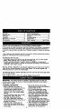
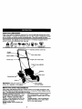
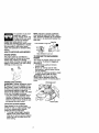
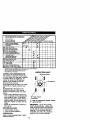
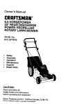
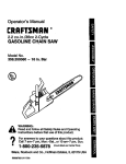
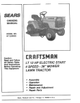
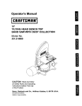
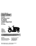
Owner's Manual
ICRRFTSMRN'I
6.0 HORSEPOWER
22" SIDE DISCHARGE
ROTARY LAWN MOWER
Model No.
917,378060
•
•
•
•
Safety
•
•
EspaRol
Repair Parts
Assembly
Operation
Maintenance
CAUTION:
Read and follow all
Safety Rules and Instructions
before operating this equipment
Sears, Roebuck
and Co., Hoffman Estates, IL 60179
Visft our Craftsman web_te:www, sears.conVcra ftsman
Warranty ...............................................
Safety Rules .........................................
Assembly ..............................................
Operation ..............................................
Maintenance Schedule ......................
Maintenance .......................................
2
2
5
6
10
10
Product Specifications ........................ 11
Service and Adjustments .................... 14
Storage ...............................................
16
Troubleshooting .................................
17
Repair Parts ........................................
37
Parts Ordering ..................... Back Cover
LIMITED TWO YEAR WARRANTY ON CRAFTSMAN
POWER MOWER
For two years from date of purchase, when this Craftsman Lawn Mower is maintained,
lubricated, and tuned up according to the operating and maintenance instructions in
the owner's manual, Sears will repair free of charge any defect in material or workmanship.
If this Craftsman Lawn Mower is used for commercial or rental purposes, this warranty
applies for only 90 days from the date of purchase.
This Warranty does not cover:
• Expendable items which become wom during normal use, such as rotary mower
blades, blade adapters, belts, air cleaners and spark plug.
• Repairs necessary because of operator abuse or negligence, including bent
crankshafts and the failure to maintain the equipment according to the instructions
contained in the owner's manual,
Warranty service is available by returning the Craftsman power mower to the nearest
Sears Service Center/Department in the United States. This warranty applies only
while this product is in use in the United States.
This Warranty gives you specific legal rights, and you may also have other rights which
vary from state to state.
Sears, Roebuck and Co., D/817 WA, Hoffman Estates, Illinois 60179
IMPORTANT: This cutting machine is capable of amputating hands and feet and
throwing objects. Failure to observe the following safety instructions could result in
sedous injury or death.
I.GENERAL
OPERATION
• Read, understand, and follow all
instructions on the machine and in the
manual(s) before starting. Be thoroughly familiar with the controls and
the proper use of the machine before
starting.
• Do not put hands or feet near or under
rotating parts. Keep clear of the
discharge opening at all times.
• Only allow responsible individuals,
who are familiar with the instructions, to
operate the machine.
• Clear the area of objects such as
rocks, toys, wire, bones, sticks, etc.,
which could be picked up and thrown
by the blade.
2
• Be sure the area is clear of other
people before mowing. Stop machine if
anyone enters the area.
• Do not operate the mower when
barefoot or weadng open sandals.
Always wear substantial foot wear.
• Do not pull mower backwards unless
absolutely necessary. Always look
down and behind before and while
moving backwards.
• Do not operate the mower without
proper guards, plates, grass catcher or
other safety protective devices in place.
• See manufacturer's instructions for
proper operation and installation of
accessories. Only use accessodes
approved by the manufacturer.
• Stoptheblade(s)
whencrossing
gravel
drives,
walks,or roads.
• Stop the engine (motor) whenever you
leave the equipment, before cleaning
the mower or unclogging the chute.
• Shut the engine (motor) off and wait
until the blade comes to complete stop
before removing grass catcher.
• Mow only in daylight or good artificial
light.
• Do not operate the machine while
under the influence of alcohol or drugs.
• Never operate machine in wet grass.
Always be sure of your footing: keep a
firm hold on the handle and walk;
never run.
• Disengage the self-propelled mechanism or drive clutch on mowers so
equipped before starting the engine
(motor).
• If the equipment should start to vibrate
abnormally, stop the engine (motor)
and check immediately for the cause.
Vibration is generally a waming of
trouble.
• Always wear safety goggles or safety
glasses with side shields when
operating mower.
I1. SLOPE OPERATION
Slopes are a major factor related to slip
and fall accidents which can result in
severe injury. All slopes require extra
caution. If you feel uneasy on a slope, do
not mow it.
DO:
• Keep children out of the trimming area
and under the watchful care of another
responsible adutt.
• Be alert and turn machine off if children
enter the area.
• Before and while walking backwards,
look behind and down for small
children.
• Never allow children to operate the
machine.
• Use extra care when approaching blind
corners, shrubs, trees, or other objects
that may obscure vision.
IV. SERVICE
• Use extra care in handling gasoline
and other fuels. They are flammable
and vapors are explosive.
- Use only an approved container.
- Never remove gas cap or add fuel
with the engine running. Allow
engine to cool before refueling. Do
not smoke.
- Never refuel the machine indoors.
- Never store the machine or fuel
container inside where there is an
open flame, such as a water heater.
• Never run a machine inside a closed
area.
• Never make adjustments or repairs
with the engine (motor) running.
Disconnect the spark plug wire, and
keep the wire away from the plug to
prevent accidental starting.
• Keep nuts and bolts, especially blade
attachment bolts, tight and keep
equipment in good condition.
• Mow across the face of slopes: never
• Never tamper with safety devices.
up and down. Exemise extreme
Check their proper operation recjularly.
caution when changing direction on
• Keep machine free of grass, leaves, or
slopes.
other debds build-up. Clean oil or fuel
• Remove obstacles such as rocks, tree
spillage. Allow machine to cool before
limbs, etc.
storing.
• Watch for holes, ruts, or bumps. Tall
• Stop and inspect the equipment if you
grass can hide obstacles.
DO NOT;
strike an object. Repair, if necessary,
before restarting.
• Do not trim near drop-offs, ditches or
• Never attempt to make wheel height
embankments. The operator could lose
adjustments while the engine (motor) is
footing or balance.
running.
• Do not trim excessively steep slopes.
•
Grass catcher components are subject
• Do not mow on wet grass. Reduced
to wear, damage, and deterioration,
footing could cause slipping.
which could expose moving parts or
III. CHILDREN
allow objects to be thrown. Frequently
Tragic accidents can occur if the operator
chock components and replace with
is not alert to the presence of children.
manufacturer's recommended parts,
Children are often attracted to the
when necessary.
machine and the mowing activity. Never
• Mower blades are sharp and can cut.
assume that children will remain where
Wrap the blade(s) or wear gloves, and
you last saw them.
use extra caution when servicing them.
• Do not change the engine governor
3
setting or overspeed the engine.
ALookforthissymbol
topointout
important
safetyprecautions.
It means
CAUTION!!I
BECOMEALERTI!!
YOUR
SAFETY
ISINVOLVED.
AWARNING: Engine exhaust, some of its
constituents, and certain vehicle components contain or emit chemicals known to
the State of California to cause cancer
and birth defects or other reproductive
harm.
_WARNING:
Battery posts, terminals and
related accessories contain lead and
lead compounds, chemicals known to the
State of California to cause cancer and
birth defects or other reproductive harm.
Wash hands after handling.
A WARNING." In order to prevent
accidental starting when setting up,
transporting, adjusting or making repaim,
always disconnect spark plug wire and
place wire where it cannot contact spark
plug.
These accassodss were availablewhen thislawn mower was produced. They are not
shipped with your mower. They am also availableat most Sears retail outletsand service
canters. Most Sears stores can also order repairpads for you, when you providethe model
number of your lawn mower. Some of these accessoriesmay not apply to your lawn mower.
LAWN MOWER PERFORMANCE
FOR REAR OISCHARGE LAWN MOWERS
MULCHER KITS
GRASS CATCHERS
GRASS CATCHERS
FOR
REAR DISCHARGE
LAWN MOWERS
STABILIZER
FOR
I
SIDE DISCHARGE
LAWN MOWERS
GAS CANS
LAWN MOWER MAINTENANCE
MUFFLERS
BELTS
AIR RLTESS
BLADES
BLADE ADAPTERS
4
SPARK PLUGS
WHEELS
ENGINE OIL
Read these instructions and this manual
in its entirety before you attempt to
assemble or operate your new lawn
HOWTO SET UPYOUR
MOWER
TO UNFOLD HANDLE
mower.
LAWN
IMPORTANT: This lawn mower is
shipped WITHOUT OIL OR GASOLINE in
the engine.
Your new lawn mower has been assembled at the factory with the exception
of those parts left unassembled for
shipping purposes. All parts such as nuts,
washers, bolts, etc., necessary to complete the assembly have been placed in
the parts bag. To ensure safe and proper
operation of your lawn mower, all parts
and hardware you assemble must be
tightened securely. Use the correct tools
as necessary to ensure proper ffghtness.
TO REMOVE LAWN MOWER FROM
CARTON
IMPORTANT: Unfold handle carefully so
as not to pinch or damage control cables.
1. Raise handles until lower handle
section locks into place in mowing
position.
2. Remove protective padding, raise
upper handle section into place on
lower handle and tighten both handle
knobs.
3. Remove handle padding holding
operator presence control bar to
upper handle.
Your lawn mower handle can be adjusted
for your mowing comfort. Refer to "Adjust
Handle" in the Service and Adjustments
section of this manual.
1. Remove loose parts included with
mower.
2. Cut down two end corners of carton
and lay end panel down flat.
3. Remove all packing materials except
padding between upper and lower
handle and padding holding operator
presence control bar to upper handle.
4. Roll lawn mower out of carton and
check carton thorougly for additional
loose parts.
Operator p
control bar
Upper handle
Liftup
Mowing
handle
5
KNOWYOUR LAWN MOWER
READ THIS OWNER'S MANUAL AND SAFETY RULES BEFORE OPERATINGYOUR
LAWN MOWER. Compare the illustrationswith your lawn mower to familiarizeyourself
withthe locationof variouscontrolsand adjustments. Save this manualfor future
These symbols may appear on your lawn mower or in literature supplied with the
product. Learn and understand their meaning.
CAUTION
ENGINE
OR WARNING
ON
ENGINE
OFF
FAST
SLOW
CHOKE
FUEL
OIL
DANGER. KEEP HAH_S
At_O FEET AWAY
presence control bar
Throttle
contr(
control lever
Handle knob
Engine oil cap w/dipstick
Housing
Gasolinefiller
IMPORTANT: This lawn mower is shipped
without oil or gasoline in the engine.
MEETS
CPSC SAFETY
adjustor
(on every wheel)
REQUIREMENTS
Sears rotary walk-behind power lawn mowers conform to the safety standards of the
American National Standards Institute and the U.S. Consumer Product Safety Commission, The blade turns when the engine is running.
Operator presence control bar - must
be held down to the handle to start the
engine. Release to stop the engine.
Primer - pumps additional fuel from the
carburetor to the cylinder for use when
starting a cold engine.
Sta .rter handle- used for starting the
engine.
Drive control lever - used to engage
power-propelled forward motion of lawn
mower.
Throttle control - Used for starling the
engine and allows you to select either
fast or slow engine speed,
Theoperation
ofanylawn
mowercan resultin
NOTE: Adjuster is properly positioned
when plate tab inserts into hole in lever.
Also, g-position adjusters (if so equipped)
allow lever to be positioned between the
plate tabs.
PlateTab
foreign objects thrown into
the eyes, which can result
in severe eye damage.
Always wear safety glasses or eye
shields while operating your lawn mower
or performing any adjustments or repairs.
We recommend a wide vision safety
mask over spectacles or standard safety
glasses.
HOWTO USEYOUR
LAWN MOWER
ENGINE
LowerWheels for High Cut
_,
Lever
RaiseWheels for Low Cut
SPEED
TO CONVEFITTO
MOWER
The engine speed is controlled by a
throttle located on the side of the upper
handle. Fast position is for starting,
normal cutting, trimming and better grass
bagging. Slow position is for light cutting,
trimming and fuel economy.
,_
Fast
I
DISCHARGING
Your mower is shipped ready to be used
as a mulcher. To convert to bagging or
discharging:
• Lift discharge guard and remove
muloher plate.
• Mower can now be used for side
discharging or optional grass catcher
can be attached.
• To return to mulching operation, simply
reinstall mulcher plate as shown.
ACAUTION:
Do not run your lawn
mower without discharge guard, approved grass catcher or mulcber plate in
place.
Dischargeguard
Slow
," - .
ENGINE ZONE CONTROL
_CAUTION:
Federal regulations require
an engine control to be installed on this
lawn mower in order to minimize the dsk
of blade contact injury. Do not under any
circumstances attempt to defeat the
function of the operator control. The blade
turns when the engine is running.
• Your lawn mower is equipped with an
operator presence control bar which
requires the operator to be positioned
behind the lawn mower handle to start
and operate the lawn mower.
\
Mulcher
TO ADJUST CUTTING HEIGHT
Raise wheels for low cut and lower
wheels for high cut, adjust cutting height
to suit your requirements. Medium
position is best for most lawns.
• To change cutting height, squeeze
adjuster lever toward wheel. Move
wheel up or down to suit your requirements. Be sure all wheels are in the
same setting.
7
plate
DRIVE CONTROL
ADD GASOLINE
• Selfopropelling is controlled by holding
the operator presence control bar down
to the handle and pushing the drive
control lever forward until it clicks; then
releasing the lever.
• Forward motion will stop when the
operator presence control bar is
released. To stop forward motion
without stopping engine, release the
operator presence control bar slightly
until the drive control disengages. Hold
operator presence control bar down
against handle to continue mowing
without self-propelling.
• To keep drive control engaged when
turning corners, push down on handle
and lift front wheels off ground while
turning lawn mower.
NOTE: Before filling fuel tank, remove
and discard the debris plug that is inside
the tank,
• Fill fuel tank. Use fresh, clean, regular
unleaded gasoline with a minimum of
87 octane. Do not mix oil with gasoline. Purchase fuel in quantities that
can be used within 30 days to assure
fuel freshness.
AWARNING:
Experience indicates that
alcohol blended fuels (called gasohol or
using ethanol or methanol) can attract
moisture which leads to separation and
formation of acids during storage. Acidic
gas can damage the fuel system of an
engine while in storage. To avoid engine
problems, the fuel system should be
emptied before storage of 30 days or
longer. Drain the gas tank, start the
engine and let it run until the fuel lines
and carburetor are empty. Use fresh fuel
next season. See Storage Instructions for
additional information. Never use engine
or carburetor cleaner products in the fuel
tank or permanent damage may occur.
_k CAUTION: Fill to bottom of gas tank
filler neck. Do not overfill. Wipe off any
spilled oil or fuel. Do not store, spill or
use gasoline near an open flame.
Operator presence control bar
"" control
"v, control
To engage
drive control
Drive control
disengaged
Gasoline filler cap
BEFORE
ADD OIL
STARTING
ENGINE
Your lawnmower is shipped without oil in
the engine. Engine holds 20 oz. of oil.
For type and grade of oil to use, see
=ENGINE" in Maintenance section of this
manual.
1. Be sure lawnmower is level and area
around oil fill is clean.
2. Remove engine oil cap and fill to the
full line on the dipstick. Pour oil slowly.
Do not over fill.
NOTE: Allow oil to settle down into engine
for accurate dipstick reading. To read
proper level, tighten engine oil cap, then
remove it to read the dipstick.
3. Reinstall engine oil cap and tighten.
• Check oil level before each use. Add
oil if needed. Fill to full line on dipstick.
• Change the oil after every 25 hours of
operation or each season. You may
need to change the oil more often
under dusty, dirty conditions.
(I
debris plug
inside)
TO START ENGINE
NOTE: Due to protective coatings on the
engine, a small amount of smoke may be
present dudng the initial use of the
product and should be considered
normal.
1. To start a cold engine, push primer
three (3) times before trying to start.
Use a firm push. This step is not
usually necessary when starting an
engine which has already run for a
few minutes.
2, Move throttle control lever to fast
position.
3. Hold operator presence control bar
down to the handle and pull starter
handle quickly. Do not allow starter
8
robe to snap back.
MOWINGTIPS
MULCHING MOWING TIPS
IMPORTANT: For best performance,
keep mower housing free of built-up
grass and trash. See =Cleaning" in
MAINTENANCE section of this manual.
• The special mulching blade will recur
the grass clippings many times and
reduce them in size so that as they fall
onto the lawn they will disperse into the
grass and not be noticed. Also, the
mulched grass will biodegrade quickly
to provide nutrients for the lawn.
Always mulch with your highest engine
(blade) speed as this will provide the
best recurring action of the blades.
• Avoid cutting your lawn when it is wet.
Wet grass tends to form clumps and
interferes with the mulching acflon. The
best time to mow your lawn is the eady
afternoon. At this time the grass has
dried and the newly cut area will not be
exposed to the direct sun.
• For best results, adjust the lawn mower
cutting height so that the lawn mower
cuts off only the top one-third of the
grass blades. If the lawn Is overgrown it
will be necessary to raise the height of
cut to reduce pushing effort and to keep
from ovedoading the engine and
leaving clumps of mu_ched grass. For
extremely heavy mulching, reduce your
width of cut by overlapping previously
cut path and mow slowly.
• Certain types of grass and grass
conditions may require that an area be
mulched a second time to completely
hide the clippings. When doing a
second cut, mow across or perpendicular to the first cut path.
• Change your cutting pattem from week
to week. Mow north to south one week
then change to east to west the next
week. This will help prevent matting
and graining of the lawn.
• Under corta'm conditions, such as very
tail grass, it may be necessary to raise
the height of cut to reduce pushing
effort and to keep from overloading the
engine and leaving clumps of grass
clippings. It may also be necessary to
reduce ground speed and/or run the
lawn mower over the area a second
time.
• For extremely heavy cutting, reduce the
width of cut by overlapping previously
cut path and mow slowly,
• For better grass bagging and most
cutting conditions, the engine speed
should be set in the fast positiwn.
• For side discharge lawn mowers,
cutting in a counter-clockwisa direction,
starting at the outside of the area to be
cut, spreads grass clippings more
evenly and puts less load on the
engine. To keep clippings off of
walkways, flower beds, etc., make the
first cuts in a clockwise direction.
• Pores in cloth grass catchers can
become filled with dirt and dust with
usa and catchers will collect less grass.
To prevent this, regularly hose catcher
off with water and let dry before using.
• Keep top of engine around starter clear
and clean of grass clippings and chaff.
This will help engine air flow and
extend engine life.
Max. 1/3
9
MA,N,E.ANCESCHE°°LE
REGULAR
SERVICE
M
O
d,,*f__'9,_/_._"
Check for Loose Fasteners
Clean/Inspect Grass Catcher
(If Equipped)
clean Lawn Mower
SERVICE DATES
I_
I_
I_
I_
IPower-Propelled
Clean
Under DriveMowers)
Cover
Check drive beW Ileys
I_
i,'
I/
R
E
V'
Chack/Shaq_dReplace
Blade
I_ 2
L_atlon
Chart
Clean Battery/Recha
IElectdc Start Mowe_sr_e
E Check EncjIne Oil Level
N Change
Engine Oil
G
t_
I_
I/'1.2
Clean Air Filter
I_
N
inspect Muffler
Clean or Replace Spark Plug
i_
(i/
S
Replace Air Filter Paper Cadddge
li/2
|
1 - Change more clten when opecating under a heavy load o¢ in high an_nl
2 - Service more o_en when Operating in dirty06"dusty conditions.
3 - Replace blade_ mo,'e o_
when mowing in sandy SOil.
4 ° Charge 48 hours at end of season,
GENERAL
1_4
!_
2
temperatures,
LUBRICATION
RECOMMENDATIONS
The warranty on this lawn mower does
not cover items that have been subjected
to operator abuse or negligence. To
receive full value from the warranty,
operator must maintain mower as
instructed in this manual.
Some adjustments will need to be made
periodically to properly maintain your
unit.
All adjustments in the Service and
Adjustments section of this manual
should be checked at least once each
season.
• Once a year, replace the spark plug,
clean or replace air filter element and
check blade for wear. A new spark
plug and clean/new air filter element
assures proper air-fuel mixture and
helps your engine run better and last
longer.
• Follow the maintenance schedule in
this manual.
BEFORE EACH USE
1. Check engine oil level.
2. Check for loose fasteners.
LUBRICATION
Keep unit well lubdcated (See "LUBRICATION CHART").
CHART
(_ Wheel Adjuster
\
(_ Handle bracket
mountingpin
(_
Refer to maintenance "Engine" eectlon.
Spray lubricant
IMPORTANT:
Do not oil or grease
plastic wheel beadngs, viscous lubricants will attract dust and dirt that will
shorten the life of the self-lubdcating
beadngs, if you feel they must be
lubdcated, use only a dry, powdered
graphite type lubricant sparingly.
10
PRODUCT
SPECIFICATIONS
SERIAL NUMBER
DATE OF PURCHASE
GASOLINE CAPACITY/TYPE:
1.6 QUARTS
UNLEADED REGULAR
OlLTYPE (API-SF-SJ):
OIL CAPACITY:
SAE 30 (ABOVE 32°F)
SAE 5W-30 (BELOW 32°F)
20 OZS.
SPARK PLUG(GAP: .030")
BLADE BOLT TORQUE:
CHAMPIONR J19LM OR Jt9LM
35-40 FT. LBS.
The model and sedal numbers will be found on a decal attached to the rear of the
lawn mower housing.Record both sedal number and date of purchase in space
provided above.
LAWN MOWER
Always observe safety rules when
performing any maintenance.
TIRES
• Keep tires free of gasoline, oil, or insect
control chemicals which can harm
rubber.
• Avoid stumps, stones, deep ruts, sharp
objects and other hazards that may
cause tire damage.
BLADE CARE
For best results,mower blade mustbe
kept sharp. Replace bent or damaged
blades.
TO REMOVE BLADE
1. Disconnect spark plug wire from spark
plug and place wire where it cannot
come in contact with spark plug.
2, Turn lawn mower on its side. Make
sure air filter and carburetor are up.
3. Use a wood block between blade and
mower housing to prevent blade from
turning when removing blade bolt.
NOTE: Protect your hands with gloves
and/or wrap blade with heavy cloth.
4. Remove blade bolt by turning counterclockwise.
5. Remove blade and attaching hardware (bolt, lock washer and hardened
washer).
NOTE: Remove the blade adapter and
check the key inside hub of blade
adapter. The key must be in good condition to work properly. Replace adapter if
damaged.
TO REPLACE BLADE
1. Position the blade adapter on the
engine crankshaft. Be sure key in
adapter and crankshaft keyway are
aligned.
2. Position blade on the blade adapter
aligning the two (2) holes in the blade
with the raised lugs on the adapter.
3. Be sure the trailing edge of blade
(opposite sharp edge) is up toward
the engine.
4. Install the blade bolt with the lock
washer and hardened washer into
blade adapter and crankshaft.
5. Use block of wood between blade and
lawn mower housing and tighten the
blade bolt, turning clockwise.
• The recommended tightening torque is
35-40 ft. Ibs.
IMPORTANT: Blade bolt is grade 8 heat
treated.
TO SHARPEN BLADE
NOTE: We do not recommend sharpening blade - but if you do, be sure the
blade is balanced.
Care should be taken to keep the blade
balanced. An unbalanced blade will
cause eventual damage to lawn mower
or engine.
• The blade can be sharpened with a file
or on a grinding wheel. Do not attempt
to sharpen while on the mower.
• To check blade balance, ddve a nail
into a beam or wall. Leave about one
inch of the straight nail exposed. Place
center hole of blade over the head of
the nail. If blade is balanced, it should
remain in a horizontal position. If either
end of the blade moves downward,
sharpen the heavy end until the blade
is balanced.
11
Blade
adapter
Key,._._..__/
Lockwasher__
_
• If lubdcant is required, use only Texaco
Starplex Premium I Grease, Part No.
Crankshaft 750369.
Do not substitute.
keyway
ENGINE
LUBRICATION
Use only high quality detergent oil rated
with API service classification SF-SJ.
Select the oirs SAE viscosity grade
according to your expected operating
temperature.
washer
GRASS
edge
CATCHER
(If so equipped)
• The gross catcher may be hosed with
water, but must be dry when used.
• Check your grass catcher often for
damage or deterioration. Through
normal use it will wear, If catcher
needs replacing, replace only with a
manufacturer approved replacement
catcher. Give the lawn mower model
number when ordering.
DRIVE WHEELS
Check front drive wheels each time
before you mow to be sure they move
freely.
The wheels not turning freely means
trash, grass cuttings, etc. are in the drive
wheel area and must be cleaned to free
ddve wheels.
If necessary to clean the drive wheels,
check both front wheels.
1. Remove hubcaps, hairpin cotters and
washers.
2. Remove wheels from wheel adjusters.
3. Remove any trash or grass cut_mgs
from inside the dust cover, pinion and/
or ddve wheel gear teeth.
4. Put wheels back in place.
NOTE: If alter cleaning, the ddve wheels
do not turn freely, contact your nearest
authorized service center.
GEAR CASE
• To keep your ddve system working
properly, the gear case and area
around the ddve should be kept clean
and free of trash build-up. Clean under
the drive cover twice a season.
• The gear case is filled with lubricant to
the proper level at the factory. The only
time the lubricant needs attention is if
service has been performed on the
gear case.
NOTE: Although multi-viscosity oils
(5W30, 10W30 etc.) improve starting in
cold weather, these multi-viscosity oils
will result in increased oil consumption
when used above 32°F. Check your
engine oil level more frequently to avoid
possible engine damage from running
low on oil.
Change the oil after"every 25 hours of
operation or at least once a year if the
lawn mower is not used for 25 hours in
one year.
Check the crankcase oil level before
starting the engine and after each five (5)
hours of continuous use. Tighten oil plug
securely each time you check the oil
level.
TO CHANGE ENGINE OIL
NOTE: Before tipping lawn mower to
drain oil, drain fuel tank by running
engine until fuel tank is empty.
1. Disconnect spark plug wire from spark
plug and place wire where it cannot
come in contact with spark plug.
2. Remove engine oil cap; lay aside on a
clean surface.
3. Tip lawn mower on its side as shown
and drain oil into a suitable container.
Rock lawn mower back and forth to
remove any oil trapped inside of
engine,
4. Wipe off any spilled oil on lawn mower
and on side of engine.
5. Fill engine with oil. (See =Add Oil" in
the Operacion section of this manual.)
6. Reconnect spark plug wire to spark
plug.
12
Container
AIR FILTER
Your engine will not run properly and may
be damaged by using a dirty air filter.
Replace the air filter every year, more
often if you mow in very dusty, dirty
conditions.
TO
I.
2.
3.
CLEAN AIR FILTER
Loosen screw and tilt cover to remove.
Carefully remove cartridge.
Clean by gently tapping on a flat
surface. If very dirty, replace cartridge.
_kCAUTION:
Petroleum solvents, such as
kerosene, are not to be used to clean
cartridge. They may cause deterioration of
the cartridge. Do not oil cartridge. Do not
use pressurized air to clean or dry
cartridge.
4. Install cartridge, then replace cover
making sure the tabs are aligned with
the slots in the back plate. Fasten
screw securely.
Cover
tabs
Back
Lip
Slots
MUFFLER
Inspectand replacecorrodedmuffleras it
could create a fire hazard and/or damage.
SPARK PLUG
Change your spark plug each year to
make your engine start easier and run
better. Set spark plug gap at .030 inch.
CLEANING
IMPORTANT: For best performance,
keep mower housing free of built-up
grass and trash, Clean the underside of
your mower after each use.
_CAUTION:
Disconnect spark plug wire
from spark plug and place wire where it
cannot come in contact with the spark
plug.
• Clean the underside of your lawn
mower by scraping to remove build-up
of grass and trash.
• Clean engine often to keep trash from
accumulating. A clogged engine runs
hotter and shortens engine life.
• Keep finished surfaces and wheels free
of all gasoline, oil,etc.
• We do not recommend using a garden
hose to clean lawn mower unless the
electrical system, muffler, air filter and
carburetor are covered to keep water
out. Water in engine can result in
shortened engine life.
CLEAN UNDER DRIVE COVER
Clean under drive cover at least twice a
season. Scrape underside of cover with
putty knife or similar tool to remove any
build-up of trash or grass on underside of
drive cover.
Cover
Cartridge
13
_kCAUTION:
Before performing any
service or adjustments:
1. Release control bar and stop engine.
2. Make sure the blade and all moving
parts have completely stopped.
3. Disconnect spark plug wire from spark
plug and place where it cannot come
in contact with plug.
LAWN MOWER
TO ADJUST CU1"t'ING HEIGHT
See "TO ADJUST CUTTING HEIGHT" in
the Operation section of this manual.
REAR DEFLECTOR
The rear deflector, attached between the
rear wheels of your mower, is provided to
minimize the possibility that objects will
be thrown out of the rear of the mower
into the operator's mowing position. If the
deflector becomes damaged, it should be
replaced.
DISCHARGE GUARD
The discharge guard, attached to the
discharge opening of your lawn mower, is
provided to prevent the possibility of
injury resulting from _ojects be'trig thrown
out of the discharge opening into the
operator mowing position. If the discharge
guard becomes damaged, it should be
replaced.
TO REMOVE/REPLACE DRIVE BELT
t. Remove ddve cover. Remove belt
from gearcase pulley by pushing
down on pulley and rolling belt off it.
2. Turn lawn mower on its side with air
filter and carburetor up.
3. Remove blade.
4. Remove debris shield.
5. Remove belt from engine pulley on
crankshaft.
6. Install new belt by reversing above
steps.
7. Always use factory approved belt to
assure fit and long life.
!
,
TO ADJUST HANDLE
The handle can be mounted in a high or
low position. The mounting holes in the
bottom of lower handle are off center for
raising or lowering the handle.
1. Remove upper handle and all parts
attached to lower handle.
2. Remove hairpin cotters from lower
handle bracket mounting pin.
3. Squeeze lower handle in to remove it
from mounting pins.
4. Turn lower handle over to raise or
lower handle.
5. Squeeze lower handle in and position
holes onto mounting pins on handle
bracket.
6. Reassemble upper handle and all
parts removed from lower handle.
Lower
handle
ENGINE
ENGINE SPEED
Your engine speed has been factory set.
Do not attempt to increase engine speed
or it may result in personal injury. If you
believe that the engine is running too fast
or too slow, take your lawn mower to an
authorized service center for repair and
adjustment.
CARBURETOR
Your carburetor has a non-adjustable
fixed main iet for mixture control. If your
engine does not operate properly due to
suspected carburetor problems, take your
lawn mower to an authodzed service
center for repair and/or adjustment.
IMPORTANT: Never tamper with the
engine governor, which is factory set for
proper engine speed. Overspeeding the
engine above the factory high speed
setting can be dangerous. If you think the
engine-governed high speed needs
adjusting, contact your nearest authorized service center, which has proper
equipment and experience to make any
necessary adjustments.
14
Immediately prepare your lawn mower for
storage at the end of the season or if the
unit will not be used for 30 days or more.
LAWN MOWER
When lawn mower is to be stored for a
period of time, clean it thoroughly, remove
all dirt, grease, leaves, etc. Store in a
clean, dry area.
1. Clean entire lawn mower (See
"CLEANING" in the Maintenance
section of this manual).
2. Lubricate as shown in the Maintenance section of this manual.
3. Be sure that all nuts, bolts, screws,
and pins are securely fastened.
Inspect moving parts for damage,
breakage and wear. Replace if
necessary.
4. Touch up all rusted or chipped paint
surfaces; sand lightly before painting.
HANDLE
You can fold your lawn mower handle for
storage.
1, Squeeze the bottom ends of the lower
handle toward each other until the
lower handle clears the handle
bracket, then move handle forward.
2, Loosen upper handle mounting bolts
enough to allow upper handle to be
folded beck.
IMPORTANT: When folding the handle
for storage or transportation, be sure to
fold the handle as shown or you may
damage the control cables.
• When setting up your handle from the
storage position, the lower handle will
automatically lock into the mowing
position.
Operator presence controlbar
Upper Handle _
Fold
_.
forwardfor
."_\/
s,ora o
_i -,*'_ L:.:.:;
_
Low
,;"
_
::!
Y"
,'&/,;,,,_)
//_
_ backward
\
Mowing
position
FUEL SYSTEM
IMPORTANT: It is important to prevent
gum deposits from forming in essential
fuel system parts such as carburetor, fuel
filter, fuel hose, or tank during storage.
Also, experience indicates that alcohol
blended fuels (called gasohol or using
ethanol or methanol) can attract moisture
which leads to separation and formation
of acids dudng storage. Acidic gas can
damage the fuel system of an engine
white in storage.
1, Drain the fuel tank.
2. Start the engine and let it run until the
fuel lines and carburetor are empty.
• Never use engine or carburetor cleaner
products in the fuel tank or permanent
damage may occur.
• Use fresh fuel next season.
NOTE: Fuel stabilizer is an acceptable
alternative in minimizing the formation of
fuel gum deposits dudng storage. Add
stabilizer to gasoline in fuel tank or
storage container. Always follow the mix
ratio found on stabilizer container. Run
engine at least 10 minutes after adding
stabilizer to allow the stabilizer to reach
the carburetor. Do not drain the gas tank
and carburetor if using fuel stabilizer.
ENGINEOIL
Drain oil (with engine warm) and replace
with clean engine oil. (See "ENGINE" in
the Maintenance section of this manual).
CYLINDER
1. Remove spark plug.
2. Pour one ounce (29 ml) of oil through
spark plug hole into cylinder.
3. Pull starter ha;_dle slowly a few times
to distribute oil.
4. Replace with new spark plug.
OTHER
• Do not store gasoline from one season
to another.
• Replace your gasoline can if your can
starts to rust. Rust and/or dirt in your
gasoline will cause problems.
• If possible, store your unit indoors and
cover it to give protection from dust and
dirt.
• Cover your unit with a suitable protective cover that does not retain moisture. Do not use plastic. Plastic cannot
breathe which allows condensation to
form and will cause your unit to rust.
15
IMPORTANT: Never cover mower while
engone and exhaust areas are still warm.
TROUBLESHOOTING
PROBLEM
)oes not start
,A CAUTION:Never store the lawn mower
with gasoline in the tank inside a building
where fumes may reach an open flame or
spark. Allow the engine to cool before
stodng in any enclosure.
CHART
CORRECTION
CAUSE
1. Dirty air filter.
!2. Out of fuel.
3. Stale fuel.
4. Water in fuel.
5. Spark plug wire is
disconnected.
6. Bad spark plug.
7. Loose blade or bmken
blade adapter.
8. Control bar in released
position.
9. Control bar defective.
.oss of power
1. Rear of lawn mower
housing or cutting blade
dragging in heavy grass.
2. Cutting too much grass.
3. Dirty air filter.
4. Buildup of grass, leaves,
and trash under mower.
5. Too much oil in engine.
6, Walking speed too fast.
Poorcutineven
1. Worn, bent or loose blade.
2. Wheel heights uneven.
3. Buildup of grass, leaves
and trash under mower.
:.xoessive
ribration
1. Wom, bent or loose blade.
2. Bent engine crankshaft.
_tarter rope hard
opull
1. Engine flywheel brake is on
when control bar is released
2. Bent engine crankshaft.
3. Blade adapter broken.
4. Blade dragging in grass.
16
1. Cleardreplaceair filter.
2. Fill fuel tank.
3. Drain tank and refillwith
fresh clean fuel.
4. Drain fuel tank and
carburetorand refilltank
with fresh gasoline,
5. Connect wire to plug.
6. Replace spark plug.
7. Tighten blade bolt or
replace blade adapter.
8. Depress control bar to
handle.
9. Replace control bar.
1. Sat to "Higher Cut"
position.
2. Set to "Higher Cut"
position.
3. Clean/replace air filter.
4. Clean underside of mower
housing.
5. Check oil level.
6. Cut at slower walking
speed.
1. Replace blade. Tighten
blade bolt.
2. Set all wheels at same
height
3. Clean underside of
mower housing.
1. Replace blade. Tighten
blade bolt.
2. Contact a Sears or other
qualified service center.
1. Depress controlbar to
upper handle before
pullingstarter rope.
2. Contacta Sears or other
qualifiedservice center.
3. Replace blade adapter.
4. Move lawn mower to cut
grass or to hard surface.
TROUBLESHOOTING
PROBLEM
CHART
CAUSE
CORRECTION
.oss of drive
1. Drive wheels not turning
with drive control engaged,
2. Belt not driving
1. Adjust or replace drive
control cable.
2. Put belt on pulleys or
replace belts if broken,
._rass catcher
:otfilling (ifso
_luipped)
1. Cutting height too low.
2, Lift on blade worn off.
3. Catcher not venting air.
1. Raise cutting height.
2. Replace blade.
3. Clean grass catcher.
,lard to push
1. Grass is too high or wheel
height is too low,
2. Rear of lawn mower
housing or blade dragging
in grass.
3. Grass catcher too full.
4. Handle height position not
right for you.
1. Raise cutting height.
17
2. Raise rear of lawn mower
housing one (1) setting
higher.
3. Empty grass catcher.
4, Adjust handle height to
suit,
ROTARY
LAWNMOWER
-- MODEL NO. 917.378060
GEAR CASE ASSEMBLY PART NUMBER 702511
KEY
NO.
PART
NO.
1
2
3
4
6
17490416
137055X004
137Gr_3
57072
48373
7
8
9
10
11
77881
137061
137074
57079
131484
KEY
NO.
DESCRIPTION
Tapping,Screw 1/4-20 x 1-1/4
Engugement Bracket
Shifter
Seal
Gear Case Halves Kit (Includes
Key NOS. 4, and 7)
Beadng
Worm Shaft
Drive Shaft
Hardened Washer
Clutch Yoke
12
13
14
15
16
17
18
10
PART
NO.
700343
86447
137(To0
750436X
750Q69
1200(XX_
850848
81585X004
DESCRIPTION
Busing
Rug
HelicalGear
Clutch Jaw
Grease
E-F_Ug
Hi-ProKey
Spring Bracket
NOTE: Allcomponentdimensionsgiven In U.S. Inches.
1 inch= 25.4 mm
35
ROTARY
LAWNMOWER
-- MODELNO.917.378060
81
8O
43
42
19
62
4O
334,
41
42
52
ROTARY LAWN MOWER o- MODEL NO. 917.378060
KEY
NO.
1
3
5
6
7
8
9
10
12
18
19
22
23
24
25
27
28
29
33
35
36
38
39
40
41
42
43
44
45
PART
NO,
166860X479
149293
153638
146771
131959
66426
51793
136376
1515_0X479
170_16X479
17Q_45X479
140540
750097
87584X004
750149
147286
87593
87589
774OO
750085X007
146630
700331X004
701037
145935X004
62335
142748
151155
83923
7515_
DESCRIPTION
Upper Handffi
ZoneControlCa_e
RopeGuide
Contr_ Bar
Hanele Belt
Wire T_
Hffiq0_nCotter
Handle Knob
Lower Har_e
Handle Brackat Assemffiy (Left)
Harde Bracket Assembly (l_ght)
Rear Defffictor
Hex Wacher Head Screw #16-24 x 1/2
DeRect_ Bracket
Di_
Guard
Hinge Rod
Housing Bracket
Tor_on Spring
Hubcap
Wheel AdJusling Bracket
Spacer
Selector Sphog
Selector Knob
Axle Arm Assembly
Belleville Washor
Shoulder Bolt
Whsel & _m As6embly
He)( Nut
Lock.nut 3/18-16
46
85463
KEY PART
NO.
NO.
48
49
51
52
53
54
55
56
57
62
63
64
149741
63601
134612
15O406
851084
851074
141114
851514
171534
845_6
87677
68
......
71
72
73
74
75
76
78
79
80
81
- -*
..
63601
170(_1
176OO406
851201X004
751772X479
128415
700417
144929
1111gOX
83816
134_7X479
161058
17_6
DangerDecal
DESCRIPTION
Thread Cuffing Screw 5/16-18 x 3/4
Hex Locknut
Debris Shield
Hex Head Thread Rolling Screw 3/6-16 x 1-1/_
Hex Head Screw 3/6-24 x 1-3_ (Grd. 8)
Helical Lockwasher
HardenedWasher
Blade 22"
Blade Adapter
Lawn Mower Housing (Inol. Ref, #46)
Engine Pulley
Hi-Pro Key #HP 505
Engine - (See Breakdown) B&S 12H802
Locknut Keps
Front Baffle
Screw
Engk_e Washer
Mulch Plate
POp Rivet
l_roffie
Screw
Oamp
Screw
Rear Baffle (Not Shown)
Warning Decal (Not Shown)
Owner's Man uel (EnglisWSpan_h)
ROTARY LAWN MOWER -- MODEL NO. 917.378060
11
/
12
,3
"j
ROTARY LAWN MOWER - MODEL NO. 917.378060
KEY
NO.
1
2
4
5
6
7
8
11
12
13
14
15
16
18
PART
NO.
145755
751152
158755
146527
1504S5
145212
774OO
151156
12000(_68
137054
88080
88118
67725
701037
KEY
NO.
DESCRIPTION
Con_ol Cable Assembly
Locknut 1/4-20
HexWasherHeadScrew
V,.B_t
Retainer Spdng
Hex Nut
Hubcap
Wheel and Ttre Assembly
E-R_
Dust Cover
FeftWasher
Washer 1/2x1-1/2
Sstecto_ Knob
x,134
1/4 x 2.0
26
3/4
28
31
32
35
36
37
38
40
41
55
56
PART
NO.
DESCRIPTION
1436O3
Pan Head Tapping Screw #10-24 x 2-
137088
132010
137062
152018
7_11
137090
63601
75192
152019
86012
750097
DdveCover
Locknut
Ddve Pulley
Wheel Adjuster Assembly (Left)
Gear Case Assembly
Sp_ng
Locknut 1/4-20
Sp.ng
Wheel Adjuster Assembly (Right)
Ddveshaft Cover
Soew
BRIGGS & STRATTON
4-CYCLE ENGINE
Llo19 LABEL
KaTJ
MODEL NO. 12H802
TYPE NO. 2640-B1
6e4
54_
51 _._
3831
1095 VALVE
GASKET SET
lk REQUIRES SPECIAL TOOLS
TO INSTALL. SEE REPAIR
INSTRUCTION MANUAL.
11058 OWNER'S MANUAL]
20
40
/rr--_
BRIGGS & STRA'n'ON
4-CYCLE ENGINE
MODEL NO. 12H802
TYPE NO. 2640-B1
188_
445
443_
966i
_._
1591_
\i
977 CARBURETOR
GASKET SET
+'
137
3.%
+: +- _+]::
7080
276_
276
121 CARBURETOR OVERHAUL KIT
I
708 !@
137
.....
!I
._
617 \_, /_
_.
\_:.+]j 104"_%
)) 2761<++) 127_+
41
617 __ J
BRIGGS & STRATrON
4-CYCLE ENGINE
MODEL NO. 12H802
TYPE NO. 2640-B1
921
332 _
455i+_: '_i
304
305 _
592
._
_'_
58
_'
....
12_
I
-•_ 5j
459 E _._..
_,
689 C_*
1210 ___
597_
L 1036 EMISSIONS
LABEL
j
42
6O
BRIGGS & STRA'R'ON
4-CYCLE ENGINE
356
MODEL NO. 12H802
TYPE NO. 2640-B1
: .....
209
_.i "_
I e51 _,_
js
_
615 ___
404_
_
'_
/
sos
745
43
]
MODEL NO. 12H802
TYPE NO. 2640-B1
BRIGGS & STRATrON
4-CYCLE ENGINE
KEY
NO.
1
2
3
4
5
7
8
9
10
11
12
13
15
16
20
22
23
24
25
PART
NO.
DESCRIPTION
493260
Cylinder Assembly
399269
Ktt-Bushlr_/Seal
299819
• Seal-Oil (Magneto Side)
493278
Sump.Engine
691160
Head-Cylinder
692249 ,+ Gasket.Cylinder Head
695250
Breather Assembly
272481
,+ Gasket-Breather
691_25
Screw (Breather Assembly)
691781
Tube-Breather
692232
• Gasket-Crankcase
690912
Screw (Cylinder Head)
691680
Plug-Oil Drain
691451
Crankshaft
399781
• Seal-Oil (PTO Side)
691092
Screw (Er_j_r,_ Sump)
692315
Flywheel
222698
Key-Flywheel
499429
Piston Assembly (Standard)
499430
Piston Assembly (.010" O.S.)
499431
Piston Assembly (.020" O.S.)
499432
Piston Assembly (.030" O.S.)
26
499426
P,k_ Set-Piston (Standard)
499426
Ring Set-Piston (.010 _ O.S.)
499427
Ring Set-Piston (.020"O.S.)
499428
Ring Set-Piston (.030" O.S.)
27
691866
Lock-Piston Pin
28
499423
Pin-Piston
29
499424
Rod-Connecting
32
691664
Screw (Conne_Bng Rod)
32A 695759
Screw (Connecting Rod)
33
262651
Valve-Exhaust
34
262652
Valve-Intake
35
691270
Spring-Valve Intake)
36
691270
Spring-Valve (Exhaust)
40
692194
Retainer-Valve
43
691997
StinBer-GovemodOU
45
690548
Tappet-Valve
46
691449
Camshaft
48
498826
Short Block (Replacement
Engine 12J802-2915-B1)
50
497465
Manifold-Intake
51
272199
• Gasket-Intake
64
691650
Screw (Intake Manifold)
55
691421
Housing-Rewind Starter
58
692259
Rope-Starter (Cut to
Required Length)
60
281434
Grip-Starter Rope
65
690759
Screw (Rewind Starter)
81
691740
Lock-Muffler Screw
95
691636
Screw !_lhrot6e Valve)
97
493267
Sha6-Throttle
104 691242
_ Pin-Float Hinge
117 494870
Jet-Main (Standard)
497315
Jet-Main High Attitude)
121 498260
Kit-Carburetor Overhau
125 498170
Carburetor
KEY
NO.
PART
NO.
127
130
133
134
137
146
159
163
167
694468
O
691203
398187
398188
_
693981 _:
690979
691753
272653,O:_
691050
188
190
202
209
222
227
276
287
300
304
305
306
307
332
333
334
337
356
358
363
365
383
404
425
443
690877
690940
691828
690318
692031
690763
271716
690940
692038
695892
691108
690450
690345
690662
802574
691061
802592
692390
497316
19069
692524
89638
690272
690670
692523
446
455
456
459
505
523
524
526
529
562
584
585
592
597
491566
691219
692299
281505
231082
495264
692296
495266
691923
92613
692342
691879
690800
691696
£1
:1:
+
NOTE:
44
DESCRIPTION
Plug-Welch
Vatve-Thtottte
Float-Carburetor
Valve-Needle/Seat
Gasket-Float Bowl
Key-Timing
Bracket-Air Cleaner Primer
Gasket-Air Cleaner
Line-Fuel (Cut to Required
Length)
Screw (Control Bracket)
Screw (Fuel Tank)
Link-Mechanical Governor
Spring-Governor
Bracket-Control
Control Lever-Governor
O:r Sealing Washer
Screw (Dipstick Tube)
Muffler
Housing.Blower
Screw (Blower Housing)
Shield-Cylinder
Screw ((_y_h_er Shield)
Nut (Flywheel)
Armature*Magneto
Screw (Armature Magneto)
Spark Plug
Wire-Stop
Engine Gasket Set
Fbtwhsel Puller
Screw (Carburetor)
Wrench-Spark Plug
Washer (Governor Crank)
Screw (Air Cleaner Cover)
Screw (Air Cleaner Primer
Base)
F_tter-AirClearer Cartr_ge
Cup-Flywheel
Plate-Pawl Fdcgon
PawI-Ratchet
Nut (Governor Control Lever)
Dipstick
• Seal-Dipstick Tube
Tube_D_pstLck
Grommet
Bolt Governor Control Lever)
Cover-Brea her Passage
• Gasket-Breather Passage
Nut Rewind Stader)
Screw (Paw FdcUon Plate)
Included
358
Included
No. 121
Included
No. 977
I_
1095
in Engine Gasket Set, Key. No.
In Carburetor Overhaul Kit, Key.
in Carburetor Gasket Set, Key.
In VSNe Overhaul Kit, Key. No.
All component dimensions given in U.S.
inches 1 inch = 25.4 mm
BRIGGS & STRATI'ON
4-CYCLE ENGINE
KEY
NO.
PART
NO.
601
608
613
615
616
617
621
635
668
670
684
85162
Clamp-Hose
497680
Starter-Rewind
691340
Screw (Muffler)
690340
Retainer-Governor Shaft
691306
Crank-Governor
270344 _)_t SeaI-O Ring (Intake Manifold)
692310
Switch-Stop
66538
Boot-Sparkplug
493823
• Spacer (Includes 2)
692294
Spacer-Fuel Tank
690345
Screw (Breather Passage
Cover)
691855
Sprlng-Fdctlon
691321 O_t Seal*ThrotSa Shaft
691830
Gear-Timing
691648
Screw (Brake)
891031
* Sea[-O Ring (Dipstick Tube)
692017
Assembly-Dipstick/Tube
493880
TerminaI-Sparkplug
691155
Seat-Valve (Intake)
690380
Seat-Valve (Exhaust)
262001
Bushing-Guide (Exhaust)
63709
Bushing-Guide (Intake)
497233
Cover-Blower Housing
692135
Spring-Brake
695891
Brake
397974
Cap-Fuel Tank
496116
Base-Air Cleaner Primer
692298
Cover-Air Gk_ner
690700
Screw (Blower Housing
Cover)
689
708
741
745
842
847
851
869
870
871
921
922
923
957
966
968
969
DESCR|P'nON
MODEL NO. 12H802
TYPE NO. 2640-B1
KEY
NO.
PART
NO,
970
691669
972
975
976
977
1019
1036
1058
1059
1095
1210
495224
493640
496115
498261
494256
695111
274265
692311
498528
498144
1211 498144
_l
:1;
+
NOTE:
45
included
358
Included
No. 121
Included
No. 977
Included
1095
DESCRIPTION
Screw (Air Cleaner Pdmer
Bracket)
Tank-Fuel
Bowl-Float
Pdmer-Carburetor
Set-Ca_reto_
Gasket
Kit-Label
Labei-Emisslons
Owner's Manual
Kit-ScrawhNasher
Set-Valve Gasket
Assembly-Pulley/Spdng
(Pulley)
Assembly-Pulley/Spdng
(Spring)
in Engine Gasket Set, Key. No.
in Carburetor Overhaul Kit, Key.
In Carburetor Gasket Set, Key.
in Valve Overhaul Kit, Key. No.
All component dimensions given in U.S.
inches 1 inch = 25,4 mm
46
47
Get it fixed, at your home or ours!
For repair of major brand appliances In your own home...
no matter who made it, no matter who sold it!
1-800-4-MY-HOME
s"
Anytime, dayor night
(1-800-469-4663)
www.sears.com
To bring in products such as vacuums,
lawn equipment and electronics for repair, call for
the location of your nearest Sears Parts & Repair Center.
1-800-488-1222
Anytime, day or night
www.sears.com
For the replacement parts, accessories and owner's manuals
that you need to do-it-yourself, call Sears PartsDirectSM!
1-800-366-PART
(1-800-366-7278)
6 a.m.-
11 p.m.CST,
7 days a week
www.sears.com/partsdlrect
To purchase or inquire about a Sears Service Agreement:
1-800-827-6655
7 a.m.- 5 p.m.CST,Mon.- Sat.
Para pedir serviciode reparaclbn a domiclllo,
y para ordenar plezas con entrega a domicilio:
1"888"SU-HOGAR
s.
(1-888-784-6427)
AuCanada pour service en fran(;:ais:
1-877-LE-FOYER
_
(1-877-533-6937)
[ u,, s 1
H°meCen_al e J
O Sears.
w_
® Registered Trademark /
Trademark of Sears, Roebuck and Co.
® Marca ReQistrada / _'M Marca de F&brica de Sears, Roebuck and CO,
Roebuck and Co.
176226_,1_29.00
"I'R"
Printed in U.S.A.