1
Operator's
Manual
!
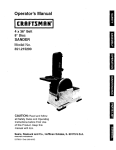
10"
TILTING HEAD BENCH TOP
BAND SAW WITH DUST COLLECTION
Model No.
351.214600
/
i
CAUTION:
\,
Read and follow
all Safety Rules and Operating
Instructions before First Use
of this Product.
Sears,
Roebuck
www,sears.com/craftsman
20859.01
Draft (05/30/03)
and
Co., Hoffman
Estates,
IL 60179
U.S.A.
•
Warranty ....................................
2
Safety Rules ...............................
Unpacking
Be alert and think clearly. Never operate power tools
when tired, intoxicated or when taking medications
that cause drowsiness,
2-3
..................................
PREPARE
3
Assembly ...................................
Installation .................................
3
4-5
Operation .................................
Maintenance .................................
5-g
9
Troubleshooting .............................
Parts Illustrations and Lists ..................
11
12-15
EspaSol .................................
16-24
WORK
AREA FOR JOB
• Keep work area clean.Cluttered work areas invite
accidents.
•
Do not use power too]s tn da,"_jereus environments.
Do not use pewit tools th damp or wet IocetJonso Do
not expose power tools to rain.
• Work area should be properly lighted.
•
Proper electricet receptacle shoutd be available for
tool. Three-prong plug should be plugged directly
into properly grounded, three-prong receptacle.
Extension cords should have s grouedlng prong and
the three wires of the extension cord should be of
the correct gauge.
•
FULL ONE YEAR WARRANTY
,, Keep visitors at a safe distance from work area.
If this product fails due to a defect In material or workmanship within one year from the date of purchase,
Sears will at Its option repair or replace It free of
charge. Contact your nearest Sears Service Center
(1-800-4-MY-HOME) to arrange for product repair, or
return this product to place of purchase for replacement.
If this product is used for commercial or rental purposes, this warranty will apply for 90 days from the date of
purchase.
This warranty applies only while this product is used in
the United States.
•
Keep children out of workplace. Make workshop
chiJdproof.Use padJesks, master switches or remove
switch keys to prevent any unintentional use of
power tools.
TOOL SHOULD
•
Always unplug tool prior to inspection.
•
Consult manual for specific maintaining and adjustIng procedures.
Keep tool lubricated and clean for safest operation.
Remove adjusting tools. Form habit of checking to
see that adjusting tools are removed before switching machine on.
•
•
This warranty gives you specific legal rights and you may
also have other rights which vary from state to state.
Sears, Roebuck and Co., Dept. 817WA, Hoffman
Estates, IL 60179
WARNING:
For your own safety, read all of the
instructions and precautions before operating tool.
CAUTION: Always follow proper operating procedures
as defined in this manual -- even if you are familiar
with use of this or similar tools. Remember that being
careless for even a fraction of a second can result in
severe personal Injury.
BE MAINTAINED
•
Keep ell parts in working order. Check to determine
that the guard or other parts wllJ operate properly
and perform their intended function.
•
Check for damaged parts. Check for alignment of
moving parts, binding, breakage, mounting and any
other cond[t[on that may affect a tool's operation.
•
A guard or other part that is damaged shou)d be
properly repaired or replaced. Do not perform
makeshift repairs. (Use parts list provided to order
replacement psrts.)
KNOW
HOWTO
USE TOOL
JOB
•
•
Wear proper apparel. Do not wear loose clothing,
gloves, neckties, rings, bracelets or other jewelry
which may get caught in moving parts of machine.
Use right tool for job. Do not force tool or attachment
to do a job for which it was not designed.
•
•
•
•
Wear protective hair covering to contain long hair.
Wear safety shoes with non-slip soles.
Disconnect tool when changing btade.
Avoid accidental start-up. Make sure that the tool is
in the "off"position before plugging in.
•
•
WearsafetyglassescomplylngwlthUnitedStates
ANSI Z87.1. Everyday glasses have only impact
resistant lenses. They are NOT safety glasses.
Do not force tool. It will work most effic)ently at the
rate for which it was designed.
•
Keep hands away from moving parts and cutting
surfaces.
•
Wear face mask or dust mask If operation Is dusty.
•
Never leave tool runnin_Junattended. Turn the power
offand do not leave tool until it comes to a complete
stop.
•
Do not overreach. Keep proper footing and balance.
BE PREPARED
FOR
© Sears, Roebuck and Co.
2
•
IMPORTANT: Table is coated with a protectant. To
ensure proper fit and operation, remove coating.
Coating is easily removed with mild solvents, such as
mineral spirits, and a soft cloth. Avoid getting solution
on paint or any of the rubber or plastic parts. Solvents
may deteriorate these finishes. Use soap and water on
paint, plastic or rubber components. After cleaning,
cover all exposed surfaces with a light coating of oil.
Paste wax is recommended for table top.
Never stand on tool. Serious injury could occur if teol
is tipped or If blade Is unintentionally contacted.
Know your tool. Learn the tool's operation, application and specific limitations.
•
•
Use recommended asoeseerles (refer to page 15).
Use of improper accessories may cause risk of
injury to persons.
•
Handle workplece correctly. Protect hands from possible Injury.
•
Turn machine off if it iams. Blade jams when it digs
too deeply into work.piece. (Motor force keeps it
stuck in the work.) DO not remove summed or cot off
pieces until the saw is turned off, unplugged and the
blade has stopped.
WARNING:
Never use highly volatile solvents. Non
flammable soNents are recommended to avoid possible
fire hazard.
WARNING: The operation of any power tool can result In
foreign objects being thrown Into the eyes, which can
result in severe eye damage. Always wear safety goggles
complying with United Stete_s ANSI 2:87.1 (shown on
package) before commencing power tool operation.
Safety goggles are available through your Sears catalog.
CAUTION: Do not attempt assembly if parts are missing. Usa operator's manual to order replacement parts.
MOUNT
•
•
Check for shipping damage. If damage has occurred, a
claim must be filed with carder. Check for completeness. Immediately report missing parts to dealer.
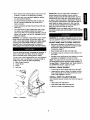
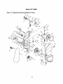
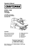
The band saw comes assembled as one unit. Additional
parts which need to be fastened to the saw should be
located and accounted for before assembling:
A Miter Gauge Assembly
B Crank Handle
C Clamp
D Dust Bag
•
BAND
SAW TO WORK
SURFACE
Band saw is designed to be portable so it can be
moved to job site, but shou)d be mounted to stable,
level bench or table. See Recommended
Accessories, page 15.
Base of band saw has four mounting holes.
If preddlled holes do not exist on work surface, drill
four holes.
•
Securely mount band ssw te work sorface by belting
(hardware not supplied) it through the holes.
NOTE: The blade must be tensioned and backed, and
the blade guides must be adjusted before operation of
the sew. Refer to =Tracking Blade" and "Blade Guides" in
the OPERATION section, pages 5, 6 and 7.
INSTALL
CRANK
HANDLE
•
Line up slot on crank handle with pin on the shaft.
•
Using maUet or piece of wood with regular hammer,
drive crank handle on the shaft until the pin on the
shaft is fully engaged in the slot.
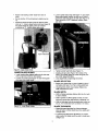
INSTALL
DUST COLLECTION
BAG
Dust collection system consists of a 30-micren bag and
clamp.
D
Figure 1 - Unpacking
3
•
Place clamp over bag sleeve.
•
•
Slide sleeve with clamp over dust port.
Secure in position by tightening clamp.
Refer to Figures 2 and 3.
MOTOR
The 115 Volt AC motor has the following specifications:
Horsepower (Maximum Developed) .............
1.0
Voltage ...................................
Amps .....................................
Hertz .....................................
115
4.6
60
Phase ..................................
RPM ....................................
POWER
Single
'_725
SOURCE
The motor Is designed for operation on the voltage and
frequency specified, Normal loads will be handled safely on voltages not more than 10% above or below the
specified voltage.
Running the unit on voltages which are not within the
range may cause overheating and motor burn.out.
Heavy loads require that the voltage at motor terminals
be no less than the voltage specified. Power supply to
the motor is contmllod by a double pole locking rocker
switch. Remove the key to prevent unauthorized use.
GROUNDING
Plug must be plugged into matching outlet that is properly Installed and grounded In accordance with all local
codes and ordinances. Do not modify plug provided. If it
will notfit in ou'dat, have proper outlet installed by a
qualified electrician.
Inspect tool cords periodically, and If damaged, have
them repaired by an authorized service facility.
Green (or green and yellow) conductor in card is the
grounding wire. tf repair or replacement of the electric
cord or plug is necassa_J, do not connect the green (or
green and yellow) wire to a live terminal
Where a 2-prong wall receptacle is encountered, it
must be replaced with a properly grounded 3-prong
receptacle installed in accordance with National Electric
Code and loca] codes and ordinances.
WARNING:
This work should be performed by a qualified elestrlc]an.
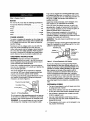
A temporary 3-prong to 2-prong grounding adapter (see
Figure 3) is available for connecting plugs to a two pole
outlet if It Is properly grounded,
GroundingLug
3-Prong Plug
- Make Sure
This Is
Connected To
A Kr_wn
Gmund
INSTRUCTIONS
WARNING:
Improper connection of equipment
grounding conductor can result in the risk of electrical
shock. Equipment should be grounded while In use to
protect operator from electrical shook,
Check with e qualified electrician if grounding instructions are not understood or if in doubt as to whether the
tool is properly grounded,
This tool is equipped with an approved 3 conductor
cord rated at 150V and a three prong grounding type
plug for your protection against shock hazards.
Grounding plug should be plugged directly into a propedy installed and grounded 3-prong grounding-type
receptacle, as shown (Figure 2).
Properly Grounded
Grounding
Outlet
Prong
2-Preng Receptacle
Figure 3 - 2-prong
Receptacle
with Adapter
Do not use a 3-prong to 2-prong grounding adapter
unless permitted by local and national codes and ordlnancas. (A 3-prong to 2-prong grounding adapter Is not
psrrnitted in Canada.) Where permitted, the rigid green
tab or terminal on the side of the adapter must be
securely connected to a permanent electrical ground
such as a propedy grounded water pipe, a properly
grounded outlet box or a properly grounded wire system.
Many cover plate screws, water pipes and outlet boxes
are not properly grounded. To ensure proper ground,
grounding means must be tested by a qualified electrician.
EXTENSION
CORDS
•
3-Prong Plug_
Figure 2 - 3-Prong
Rocelptade
Do not remove or alter grounding prong in any manner.
In the event of a malfunction or breakdown, grounding
provides a path of least resistance for electrical shock.
WARNING:
Do not permit fingers to touch the terrnlnals of plug when installing or removing from outlet.
The use of any extension cord will cause some drop
In voltage and loss of power.
• Wires of the extension cord must be of sufficient size
to carry the current and maintain adequate voltage.
• Use the table to determine the minimum wire size
(A.W.G.) extension cord.
•
Use only 3-wire extension cords having 3-preng
grounding type plugs and 3-pole receptacles which
accept the tool plug.
• If the extension cord is worn, cut or damaged in any
way, replace immediately.
EXTENSION
CORD LENGTH
Wire Size
A.W.G.
Up to 50 f_..................................
16
NOTE: Using extension cords over 50 ft. long Is not
recommended.
•
•
Keep hands away and out of line with moving parts,
Atways wear eye protection.
REMOVING
BLADE
WARNING:
Disconnect bend saw from power source
when changing or adjusting blades, Wear leather groves
when handling band saw blades, Never wear gloves
when operating saw.
Refer to Figures 4 - 13, pages 5-8.
The Craftsman 10" Tilting Head Band Saw features aluminum frame construction and a solid cast Iron table
surface to insure durability. It Is designed for cutting
hard and soft woods, as well as nonferrous metals and
plastics. Head of the saw tilts from 90° to 45 = while the
table remains in horizontal position for straight line
feeding of the matedal. The saw Is equipped with a
miter gauge for performing many different operations.
The built-in dust collection system helps to keep the
worksurface cleen. A convenient quick tensioning and
comprehensive trackJng mechanism makes blade
changing quick and easy.
•
Turn blade tensioning lever on the beck of the tooJ
clockwise all the way until it rocks in position to
release blade tension (see Figure 4).
SPECIFICATIONS
Depth of throat at 90 ° . ......................
Maximum depth of cut at 90*. ..................
Depth of throat at 45 ° . ........
9¾"
5"
7%" for 1" thick board
Flgura 4 - Blade Tensioning Lever
3" for 3" thick board
Maximum depth of cut at 45 _. .................
Table size ...........................
Table tilt .............................
33/_"
133/_x 11%"
•
Releese two latches on the side of the tool and open
front dear,
90 ° to 45 °
•
Remove table locking insert located in the front of
the table slot, take out the released blade arid
rep)aco with another blade.
Wheel diameter .............................
8"
Blade length ..............................
83%"
Blade range ........................
Blade width .............................
63% - 63%_"
1/,- _/."
Blade speed .........................
Overafl dimensions ...............
INSTALLING
•
3800 FPM
283/, x 161/sx 34"
Shipping weight ..........................
95 I_
Dust collection port .........................
2'/_"
•
BLADE
Although many of the adjustments may not be altered
when blade is removed, every adjustment should be
checked prior to using a newly installed blade,
Make sure blade teeth are pointing dawn towards
table. Turn blade inside out if necessary,
•
Slip new blade into table slot and over the upper,
loWer and Idler blade wheels. Slide blade in betWeen
blade guards.
Tension blade by turning blade tensioning taver
counterclockwise, as far as it wilt go {see Figure 4).
This is a spring loaded, tensioning mechanism and it
will auiomatlcally apply required teeslon to the blade.
Close the front door and fasten latches,
CAUTION: Always observe the following safety
precautions:
•
Make sure that blade guides and thrust bearings are
positioned and adjusted correctty to prevent sideways and rearward movement of the blade, Adjust
upper guide to just clear workplece.
•
•
Check to make sure blade is tensioned and I_acking
property. Do not over tension the blade In order to
prevent premature blade wear and breakage. Avoid
under tensioning to etiminate back and forth, side to
side blade movement as it outs.
•
•
•
Use proper blade for the curing operation.
After turning saw on, allow blade to come to full
speed before attempting any cutting operation.
•
Support workplace properly and use a smooth
steady feed to guide work through the cut, Use push
sticks or push blocks when required,
WARNING:
Be very careful; improperly tracked blade
may spring out from wheels causing serious injury. Do
not perform tracking adjustment while band saw is
running.
• Disconnect bend saw from power source.
•
Install table insert.
•
Track blade as described in the foflowing sections.
TRACKING
BLADE
•
To check the blade tracking rotate drive wheel by
hand in clockwise direction.
•
When blade is tracking properly, tighten up hex nut
and all four socket head bolts.
•
Proper tracking is achieved when drive and idler
wheels are aligned. Tracking plate (see Figure 5) on
the hack of the tool frame is used to tilt upper idler
wheel and align all three blade wheels.
•
Properly tracked blade shoutd ride at the center
height on all three wheels (drive and idlers).
BLADE
GUIDES
NOTE_ Adjust blade guides only after blade has been
properly tensioned and tracked.
• Blade guides support blade at sides and rear of
blade, and prevent twisting or deflactlon.
• Blade guides should not touch blade when no workpiece is in contact with blade. Adjust guides as
described In following section.
Set Screw
UPPER
•
BLADE
•
•
Lock adjustment by tightening set screws.
Figure 5. Tracking Plate
Loosen up hex nut.
Loosen up socket head bolts. There are four socket
head bolts holding tracking plate. Bottom socket
head bolts should be loosened just enough to allow
ttitlngof the plate. If the bottom socket head bolt Is
loosened too much, the plate will not tilt.
• Using set screws, tilt the plate In vertical (up and
down) plane until proper tracking is achieved. Upper
idler blade wheel will tilt in the same direction as
tracking plate.
•
•
•
Ba_Beadng
Guide Pin
Most of the time tracking plate should be tilted to the
desired degree as shown in Figure 6 (top of tracking
plate should be pulled away from cabinet wall, while
bottom part of tracking plate should be touching
cabinet wall).
Set Screw
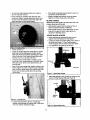
Figure 7. Upper Blade Guides
•
:igure 6 -Tracking
GUIDES
Upper blade guides employ guide pins for side
support and a ball bearing for rear support.
Loosen set screws and adjust guide pins to sides of
the b_ade (see Figure 7). Use a feeler gauge to
check that guide pins are 0.002" away from blade.
Plate
If blade rides away from cabldet, Increase gap
between tracking plate and cabinet wall. If the blade
rldas into cabinet, decrease the gap.
6
AdjUst ball bearing at rear of blade by loosening hex
nut and turning bearing shaft (see Figure 8).
ball bearing
0.002"
away from
•
•
Position
blade.
back of
•
Secure pesition of thrust bearing by tightening
nut.
•
Adjust the height of upper guide to clear the workpiece by W'. Loosen upper guide knob (see Figure 9)
and adjust height of upper guide until it clears
workplace by W'. Tighten upper guide knob.
Loosen socket head bolts (see Figure 11) and adjust
lower guide bracket position so that rear of blade is
positioned inside the groove of roller (see Figure 10).
There should be 0.002" clearance between blade
and roller.
hex
Figure 11 - Lower Blade Guide
Figure 9 - Upper Blade Guide
LOWER
•
•
BLADE
•
•
GUIDES
Lower blade guides employ guide pins for side support and grooved roller for rear support.
Loosen set screws (see Figure 10) and move guide
pins away from blade sides.
•
Tighten socket head bolts (see Figure 11).
,_djust guide pins (see Figure 10) to sides of the
blade. Use a feeler gauge to check that guide pins
are 0.002" away from blade.
Lock adjustment by tightening set screws.
BLADE
SELECTION
•
Blades vary depending on type of material, size of
workplace and type of cut that is being performed.
• Characteristics which make blades different are
width, thickness end pitch.
BLADE
•
Width of blade describes distance from tip of a tooth
to back of blade.
•
Width of blade will affect rigidity of blade. A wider
blade will wander less and produce a straighter cut.
Width of blade a!so limitsthe smallest radius which can
be cut. A ¼" wide blade can cut about a ½" radius.
•
Figure 10 - Lower Blade Guides
WIDTH
BLADE THICKNESS
• Blade thickness describes the distance between
sides of blade. A thicker blade has more rigidity end
stronger teeth.
• A narrow thick blade would be used to cut curves
while a wide thin blade would be used to make long,
straight cuts,
7
BLADE
PITCH
•
Pitch describes number of teeth per inch or tooth
size. A blade with more teeth per inch will produce a
smoother cut.
•
The type of material being cut determines number of
teeth which should be in contact with work.
•
For soft materials, the proper blade has between 6
to 8 teeth per Inch.
When cutting hard materials, where shocking is
more detrimental, use a blade with B to 12 teeth per
inch.
•
•
There should always be at least three teeth In
contact with cut to avoid shocking blade.
•
Blade shocking occurs when pitch is too large and
blade tooth encounters too much material This can
strip teeth from blade.
•
- Head Locldng Handle
Blade manufacturers are prepared to supply
information about blades for specific applications.
TYPE
OF CUT
•
Contour cutting is done by guiding werkpiece
free-handed to produce curved shapes.
•
Beveled cutting can be done by filling saw head and
using proper work guide method.
Regardless of which work guiding method is used, a
workpiece which overhangs table by more than 5"
should be properly supported
-
CONTOUR
•
•
•
SAWING
When contour sawing, use both hands to keep workpiece fiat against table and guided along desired
path.
Avoid positioning hands In line with blade. If hands
slip they could contact blade.
Try to stand to front of the saw and use hands over
the portion of table which Is to right of blade and
before cut.
Figure 13 - HL_KI TIIUng M_hanlem
MITER GAUGE
•
Use miter gauge for securing and holding werkpiece
at desired angle to produce angled cuts. Use scale
to ad._ustgauge to desired angle.
BEVEL CUTTING
WARNING:
Never use miter gauge and rip fence at
the same lime. The blade might bind in the workpiece.
Operator could be injured and/or workpiece could be
damaged.
Refer to Figure 10.
BLADE CLEANING BRUSH
•
Perform bevel cutting by tilting head to desired
degree,
•
Unlock head by loosening locking handle located on
the backside of the unit (see Figure 12).
Refer to Figure 14.
• Make sure that brush (Key No. 13) is in contact with
blade to properly remove foreign particles from drive
wheel.
•
Tilt head to desired position by rotating crank handle
(see Flgura 13).
•
Lock head in position by tightening
(see Figure 12).
•
Cut small corners by sawing around them. Saw to
remove scrap until desired shape Is obtained.
locking handle
8
WARNING:
Make certain that unit is disconnected
from power source before attempting to service or
remove any component.
CLEANING
• Keep machineand workshopclean. Do not allow
sawdustto accumulateon bandsaw.
•
Keep wheels clean. Debris on wheels will cause
poor tracking and blade slippage.
Keep mechanisms and threaded or sliding surfaces
clean and free of foreign particles.
Operate band saw with a dust collector to minimize
clean up.
•
•
LUBRICATION
•
The shielded bali bearings are permanentJy lubricated and require no further lubrication.
•
Small amounts of machine oil can be applied to belt
tension mechanisms and threaded or sliding surfaces.
• Occasionally applya coat of automobiletype wax to
table top to keep itslick and corrosion free.
KEEP BAND SAW IN REPAIR
•
If power cord is worn or cut in any way, have It
replaced.
•
Replace any damaged or missing part.
•
Use parts list to order parts.
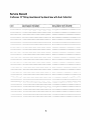
Service Record
Craftsman
IDATE
10"Tilting
Head
MAINTENANCE
Bench Top Band Saw with Dust Collection
PERFORMED
REPLACEMENT
10
PARTS REQUIRED
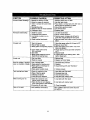
1
SYMPTOM
POSSIBLE
Excessive blade breakage
1. Material not secure on table
2. Blade too coarse for material
3. Teeth in contact with work before
sawing
4. Misaligned guides
5. Blade too thick for wheel diameter
6. Cracking at weld
1. Squarely place work:on table
2. Usa finer pitch blade
3. Placa blade in contact with work after saw is
started and has reached full speed
4. Adjust blade guides properly
5. Use thinner blade
6. Replace blade
Premature
1. Blade too coarse
2. Inadequate feed pressure
3. Hard spots or scala in or on
material
4. Blade installed backwards
1. Use finer tooth blade
2. Gently increase pressure
3. Reduce speed; ineR_se rate of feed for
scale and change blades for hard spots
4. Remove blade, twist inside out and reinstall
blade
1.Work: not square
2. Rate of feed too great
3. Blade guides not adjusted properly
4. Upper blade guide too far
from workplace
5. Dull blade
6. Blade guide assembly loose or
blade thrust bearing loose
1. Use miter gauge; adjust tilt of head at 90 °
2. Reduce rate of feed
3. Move beth guide block:s within .002" from
blade (use gauge)
4. Adjust upper guide to just clear work:piece
by¼"
5. Replace blade
6. Tighten blade thrust bearing within .002"
behind blade back
1.Too muchfeed
2. Blade too coarse
1. Reducefeed
2. Replace withfiner blade
blade dulling
Crookedcuts
Rough cuts
CORRECTIVE
CAUSE(S)
ACTION
Blade is twisting or unusual 1. Cut is binding blade
wear on side/back of blade 2. Blade guides or bearing worn
3. Blade guides or bearings not
adjusted propedy
4. Blade guide brackets loose
1. Decrease feed pressure
2. Replace
3. Adjust blade guides; see "Operation"
Teeth ripping from blade
1. Teeth too coarse for work
2. Rate of feed too great
3. Vibrating workpiece
4.Teeth filling with material
1. Use blade with finer teeth
2. Decrease feed rate
3. Hold work:piece firmly
4. Use blade with coarser teeth
Motor running too hot
1. Blade too coarse for work:
(typical when cutting pipe)
2. Blade too fine for work (typical
when cutting slick or soft material}
3. Excessive dirt and chips
1. Use blade with finer teeth
Saw will not start
Loose electrical connections
4. Tighten properly
2. Use blade with coarser teeth
3. Clean thoroughly
Have qualified electrician check electrical
connections
11
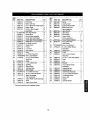
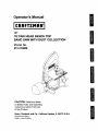
Model
Figure
14 - Replacement
Parts Illustration
31
351.214600
for Frame
32
p,_33_
4
35
5
51
52
5
\
2a
\
J
29
30
5
22
21
19
58
17
B1
IO
12
KEY
NO.
1
2
3
4
5
PART NO.
DESCRIPTION
20803.00
16080.00
00781.00
20804.00
05331.00
Front Door
6
7
8
9
10
11
12
13
14
15
18
17
18
19
20
STD851005
20805.00
20806.00
20807.00
20808.00
20862.00
STD840610
20810.00
20811,00
00090.00
02702.00
20812.00
20993.00
ST0852008
01760.00
21
22
23
24
25
26
27
28
29
20814.00
20815.00
20816.00
01680.00
20817.00
20818.00
STD841217
00351.00
20819.00
3O
31
32
20820.00
20821.00
20822.00
KEY
NO.
QTY.
PART NO.
133:
1
Switch with Key
1
4-0.7 x 8mm Pan Head Scra_ 11
Switch Plate
1
5-0.8 x 12ram Socket
18
Head Bolt
5mm Flat Washer*
4
Wheel Band
2
1
Ddve Wheel Assembly
Small Idler Wheel Band
1
1
Small Idler Wheel Assembly
Blade 63.5" x _,_"x 6 Hook
1
6-1.0ram Hex Nut*
3
Blade Brush
1
Frame
1
Line Cord
1
4
Cord Clamp
Reck
1
5 x 15ram Dowel Pin
2
6rnm Lock Washer*
3
6-1.0 x 16mm Socket
3
Head Bolt
Motor
1
1
4 x 4 x 20ram Key
1
Bushing
Strain Relief
1
1
Tracking Plate
Strain Relief
2
12-1.75mm He_ Nut*
1
6-1.0 x 10ram Set Screw
4
1
Blade Tensioning
Cam Assembly
Upper Blade Guide Assembly 1
Knob
1
1
Upper Guide Seat
13
QTY,
35
36
Spring
Locking Insert
Upper Guide Bracket
Blade Guard with
1
1
1
1
37
38
39
40
20827.00
20828.00
20829.00
20830.00
Lamp Assembly
Lamp Switch
Lamp Bulb
Cord Clamp
Lower Blade
1
1
2
1
41
42
01474.00
00361.00
43
STD85200E
01822.00
44
* Standard hardware item available _oeaW.
DESCRIPTION
20823.00
20824.00
20825.00
20826.00
45
46
47
20831.00
20832.00
03806.00
48
49
5O
51
52
20833.00
20834.00
20835.00
20836.00
06270.00
53
54
55
56
57
58
59
60
20837.00
20838.00
20839.00
20840.00
20841.00
20842.00
20994.00
20995.00
Guide Assembly
5ram Serrated Washer
5-0.8 x 8mm Pan
Head Screw
8ram Lock Washer*
8-1.25 x 20ram Socket
Head Bolt
Hinge Pivot
Cover
6-1.0 x 10ram Socket
Head Bolt
6 x 16 x 1.5ram Flat Washer
Shaft
Link
Bracket
5-0.8 x 8ram Socket
Head Bolt
Teeslonlng Rod
Teeslonlng Nut
Idler Wheel Assembly
8 x 23 x 2mm Flat Washer
Tensioning Spring
Door Latch
Sleeve
Special Washer
2
2
4
4
1
1
1
1
1
1
1
12
1
1
1
1
1
2
1
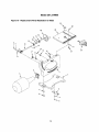
Model 351.214600
Figure
15 - Replacement
Parts Illustration
for Base
25
23
\
t
28
27
3
14
KEY
NO.
PART NO.
DESCRIPTION
1
2
3
4
5
6
7
8
9
10
11
12
13
14
15
16
17
18
19
!20
21
22
23
24
25
26
27
28
&
20843.00
20844.00
20845.00
8TD851005
05331.00
01081.00
STD851008
20776.00
20777.00
20847.00
20848.00
08182.00
STD833020
STD852006
02783.00
20849.00
STD852005
20850.00
20851.00
20852.00
8TD851006
03812.00
20853.00
20854.00
20855.00
20856.00
20857.00
20858.00
20859.00
Head Mounting Bracket
Base
QTY.
Pointer Assembly
5ram Flat Washer*
5-0,8 x 12ram Socket Head Bolt
6-1,25 x 25ram Hex Head Bolt
8ram Flat Washer*
Dust Collection Bag
Bag Clamp
Bushlr_
Lock Handle
6-1.0 x 30ram Socket Head Bolt
6-1.0 x 20ram Hex Head Bolt*
6mm Lock Washer*
4 x 18ram Spring Pin
Worm Cover
5mm Lock Washer*
Worm Shaft Assembly'
Bearing Flange
Swivel Beadn_g
6ram Flat Washer*
6-1.0 x 10ram Pan Head Screw
Crank Handle
Table with Scale
Table Insert
Table Locking Insert
6-1.0 x 28mm Wing Bolt
Miter Gauge Assembly
Operator's Manual
* Standard hardware item available locally.
Recommended
Accessories
Model No.
6
6
Multi-Purpose Stand
Blade 63.5" x '/4" x 10R
9-'22224
20860.00
&
Blade 63.5" x '/4" x 6 Hook
20861.00
A
Blade 83.5" x 3/,,,,x 6 Hook
20862.00
15
1
1
1
2
4
2
2
1
1
3
1
2
2
3
1
1
2
1
2
1
2
2
1
1
1
1
1
1
1
:¸
::::::
Your Home
::::::::
::.........
For repair-in
your home-of all major brand appliances,
lawn and garden equipment, or heating and cooling systems,
noma.er
who
ma it.
enomatter
who
so,,t,
For the replacement parts, accessories and
owner's manuals that you need to do-it-yourself.
::;:::::
For Sears professional installation of home appliances
and items like garage door openers and water heaters.
......
........
::::_::..........
....
•
:::::
............
........
1 800 4 MY HOME ®
..........
Call anytime
...........
(1-800 469-4663)
day or night (U S A. and Canada)
www.sears.com
....
;:::..........:
www.sears.ca
:::::..:
Our Home
:_:_:;
....
..........
:::
For repair of carry-in items like vacuums, lawn equipment,
and electronics, call or go on-line for the location of your nearest
:
:_:;.........
:::......
Sears Parts & Repair Center.
.........
:
1-800-488-1222
:'
Call anytime, day or night (U.S.A. only)
_,se_rs,_t_t
!!!!
To purchase a protection agreement (U,S.A.)
........... or maintenance agreement (Canada) on a product serviced by Sears:
_:::;
1-800-827-6655
(U.S.A.)
............._......
;:::::
...........
.............
_, .....-_
........-..........._
Para pedir servicio de reparacibn
a domicilio, y para ordenar pieT.as:
1-888-SU-HOGAR
(1- 888-784--6427)
_
6665
1-800-361-
(Canada)
..-..............._..................,.....,...,...._..........
Au Canada
......
:;i::
,, ....
pour service en fran_pais:
1-800-LE-FOYER _
(1-800-533-6937)
V_NW.Se_FS.Ca
!!
® Registered Trademark / TM Trademark / 8M Service Mark of 5earn, Roebuck and Co
® Mama Regis_ada / _M Mama de F&brlca / su Marca de Seevldo de Sears, Roebuc_ and Co,
ac Marque de cernrnerce / no Marque depo_de de Seam. Roebuck and Co.
!
i
® Sears, Roebuck and Co.
:,:
; :
.......