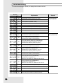
1
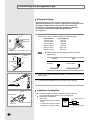
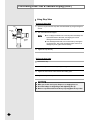
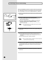
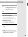
ENGLISH ESPAÑOL RUSSIAN E§§HNIKA System Air Conditioner Aire acondicionado sistemático Climatiseur numérique multifonctionnel Sistema Aria Condizionata Sistema Ar Condicionado Klimaanlage System ™‡ÛÙËÌ· ∫ÏÈÌ·ÙÈÛÌÔ‡ ëËÒÚÂÏÌ˚È ÇÓÁ‰Û¯Ì˚È äÓ̉ˈËÓÌ FRANÇAIS RVMC035EBM0 RVMC050CBM0 RVMC060GAM0 RVMC060GAM1 RVMC070FAM0 RVMC100GAM0 RVMC100FAM0 ITALIANO Cooling only RVMH050CBM0 RVMH060GBM0 RVMH060GDM0 RVMH080GAM0 RVMH100GAM0 RVMH100GCM0 RVMH100FAM0 PORTUGUÊS Heat pump DEUTSCH INSTALLATION MANUAL MANUAL DE INSTALACIÓN MANUEL D’INSTALLATION MANUALE D’INSTALLZIONE MANUAL DE INSTALAÇÃO INSTALLATIONS-HANDBUCH E°XEIPI¢IO E°KATA™TA™H™ àçëíêìäñàü èé ìëíÄçéÇäÖ E S F I P D G R DB98-05168A(2) Contents Type of outdoor unit A B C D E RVMC060GAM0 RVMC060GAM1 RVMC070FAM0 RVMH080GAM0 RVMH100GAM0 RVMH100GCM0 RVMH100FAM0 RVMC100GAM0 RVMC100FAM0 Design B-1 RVMC050CBM0 RVMH050CBM0 Model RVMC035EBM0 B-2 RVMH060GBM0 RVMH060GDM0 Chapter Chapter OUTDOOR UN I T IN S TA L L AT I O N ■ Preparation for Outdoor Unit Installation . . . . . . . . . . . . . . . . . . . . 4 ■ Deciding on Where to Install the Outdoor Unit . . . . . . . . . . . . . . . . 5 ■ Outdoor Unit Installation . . . . . . . . . . . . . . . . . . . . . . . . . . . . . . . . . 7 ■ Connecting the Cable . . . . . . . . . . . . . . . . . . . . . . . . . . . . . . . . . . . 8 ■ Piping and refnet joint selection . . . . . . . . . . . . . . . . . . . . . . . . . . 12 ■ Connecting the Refrigerant Pipe . . . . . . . . . . . . . . . . . . . . . . . . . 16 ■ Performing Leak Test & Vacuum Drying . . . . . . . . . . . . . . . . . . . 17 ■ Insulation . . . . . . . . . . . . . . . . . . . . . . . . . . . . . . . . . . . . . . . . . . . 19 ■ Adding Refrigerant . . . . . . . . . . . . . . . . . . . . . . . . . . . . . . . . . . . . 20 ■ Checking Correct Grounding . . . . . . . . . . . . . . . . . . . . . . . . . . . . 24 ■ Setting Up Option Switches . . . . . . . . . . . . . . . . . . . . . . . . . . . . . 25 ■ Functions of KEY on the Outdoor Unit PCB . . . . . . . . . . . . . . . . 26 ■ Checking and Testing Operations . . . . . . . . . . . . . . . . . . . . . . . . 28 ■ Troubleshooting . . . . . . . . . . . . . . . . . . . . . . . . . . . . . . . . . . . . . . 30 OPTIONAL ACCESSORIES ■ E-2 Parts List . . . . . . . . . . . . . . . . . . . . . . . . . . . . . . . . . . . . . . . . . . . 33 ENGLISH Chapter OUTDOOR UN I T IN S TALLATION ■ Preparation for Outdoor Unit Installation .......... 4 ■ Deciding on where to Install the Outdoor Unit . . . . . . 5 ■ Outdoor Unit Installation . . . . . . . . . . . . . . . . . . . . . . . 7 ■ Connecting the Cable . . . . . . . . . . . . . . . . . . . . . . . . . 8 ■ Piping and refnet joint selection . . . . . . . . . . . . . . . . 12 ■ Connecting the Refrigerant Pipe . . . . . . . . . . . . . . . 16 ■ Performing Leak Test & Vacuum Drying . . . . . . . . . . 17 ■ Insulation . . . . . . . . . . . . . . . . . . . . . . . . . . . . . . . . . 19 ■ Adding Refrigerant . . . . . . . . . . . . . . . . . . . . . . . . . . 20 ■ Checking Correct Grounding . . . . . . . . . . . . . . . . . . 24 ■ Setting Up Option Switches . . . . . . . . . . . . . . . . . . . 25 ■ Functions of KEY on the Outdoor Unit PCB . . . . . . . 26 ■ Checking and Testing Operations . . . . . . . . . . . . . . . 28 ■ Troubleshooting . . . . . . . . . . . . . . . . . . . . . . . . . . . . 30 E-3 Preparation for Outdoor Unit Installation Wire rope Plate protection cloth Moving the Outdoor Unit by Wire Rope Fasten the outdoor unit by two 8m or longer wire ropes as shown at the figure. To protect damage or scratches, insert a piece of cloth between the outdoor unit and rope, then move the unit. How to choose Refnet Joint A user must purchase a refnet joint to connect the indoor unit to the outdoor unit. ◆ Choose the first refnet joint depending on the table below. Distance Inner diameter (mm) (mm) Refnet joint A B C D E F G H I J K MXJ-0906A 420 80 9.7 - - 9.7 6.5 - 9.7 6.5 - MXJ-1206A 420 80 12.8 - - 12.8 9.7 MXJ-2212A 460 90 22.4 19.2 16.0 19.2 16.0 12.8 16.0 12.8 MXJ-3112A 460 90 31.9 28.7 25.6 25.6 19.2 16.0 19.2 16.0 12.8 6.5 12.8 9.7 6.5 - ◆ Choose the others according to the total capacity of indoor units. E-4 Refnet joint Total capacity of indoor units Liquid Gas 16000W or less MXJ-0906A MXJ-2212A 16000W or more MXJ-1206A MXJ-3112A ENGLISH Deciding on Where to Install the Outdoor Unit Outdoor Unit ◆ The outdoor unit must NEVER be placed on its side or upside down, as the compressor lubrication oil will run into the cooling circuit and seriously damage the unit. ◆ Choose a location that is dry and sunny, but not exposed to direct sunlight or strong winds. ◆ Do not block any passageways or thoroughfares. ◆ Choose a location where the noise of the air conditioner when running and the discharged air do not disturb any neighbours. ◆ Choose a position that enables the pipes and cables to be easily connected to the indoor unit. ◆ Install the outdoor unit on a flat, stable surface that can support its weight and does not generate any unnecessary noise and vibration. ◆ Position the outdoor unit so that the air flow is directed towards the open area. ◆ Maintain sufficient clearance around the outdoor unit, especially from a radio, computer, stereo system, etc. Indoor Unit Remote Controller Stereo 1m or m ore 1m or more Fuse ore 1.5m or m Fuse ore 1.5m or m ore 1.5m or m re o m r 1.5m o Outdoor Unit ◆ If the outdoor unit is installed at a height, ensure that its base is firmly fixed in position. ◆ Make sure that the water dripping from the drain hose runs away correctly and safely. CAUTION ◆ You have just purchased a system air conditioner and it has been installed by your installation specialist. ◆ This device must be installed according to the national electrical rules. E-5 Deciding on Where to Install the Outdoor Unit (cont.) Space Requirements for Outdoor Unit If there is no obstacle around the outdoor unit... Unit : mm 300 or more 100 or more Front 500 or more 300 or more 100 or more 100 or more 300 or more 100 or more Front 500 or more 500 or more 100 or more Front 100 or more 200 or more Front 200 or more 100 or more 100 or more 100 or more 100 or more 500 or more 100 or more ❋ Max. height of obstacle - Front side : 1500mm or less - Air inlet side : 500mm or less - Right/Left side : No limit If there is an obstacle around the outdoor unit... S1 E-6 S2 500 Air inlet Front 1500 h2 h1 Unit : mm ◆ If an obstacle in front of the outdoor unit is higher than 1500mm, the half of additional height should be added to the S1. ◆ If an obstacle behind the outdoor unit is higher than 500mm, the half of additional height should be added to the S2. ENGLISH Outdoor Unit Installation The outdoor unit must be installed on a rigid and stable base to avoid any increase in the noise level and vibration, particularly if the outdoor unit is to be installed in a location exposed to strong winds or at a height, the unit must be fixed to an appropriate support(wall or ground). Fix the outdoor unit with anchor bolts. ◆ The anchor bolt must be 20mm or higher from the base Note surface. Unit : mm Anchor bolt hole 800 660 880 932 Type A Type B 667 600 638 637 597 Anchor bolt hole Anchor bolt hole 668 440 416 390 340 364 310 Anchor bolt hole 920 1157 360 600 Type D Type C 654 990 827 807 780 Anchor bolt hole To prevent the unit against a wild animal or something, cover part after connecting the pipe. Piping Type E E-7 Outdoor Unit Installation (cont.) CAUTION ◆ Make a drain outlet around the base for outdoor unit drainage. ◆ If the outdoor unit is installed on the roof, you have to check the ceiling strength and waterproof the unit. Outdoor Unit Support Outdoor ➔ Unit ➔ Outdoor Unit Support 20mm Anchor bolt Base Surface Connecting the Cable Two electronic cables must be connected to the outdoor unit. ◆ The connection cord between indoor unit and outdoor units ◆ The power cable between outdoor unit and auxiliary circuit breaker. Example of Air Conditioner System When using ELBs for 3 phase and 1 phase Outdoor Unit MCCB 1 MCCB 3 Power cable Communication Communication ELB MCCB ELB MCCB Indoor Unit Earth When using an ELB for 3 phase 4 wires Outdoor Unit MCCB 3 ELB MCCB 3 ❋ If an outdoor unit is installed in a place in danger of an electric leak or submergence, you must install the ELB. E-8 ENGLISH Connecting the Cable (cont.) Power Cable Specification Power Supply Type of 3 Phase outdoor Power Max/Min unit MCCB ELB Supply (V) A - - - - Single Phase Power Power Max/Min MCCB Cable Length Supply (V) ELB Power Cable Length 3.5mm2, CV, 3Wires 208230V~ 253/187 /60Hz 25A 25A 5.5mm , 18m HOS-RN-F, or less 2203 Wires 240V~ 264/198 8.0mm2, HOS-RN-F, 18m~28m /50Hz 3 Wires 15A 15A - - Earth Communication Cable Cable - 2 380Frame:50A 415V~ 456/342 Trip:30A /50Hz B 208230V~ 253/187 /60Hz - - - 30A 18m or less 208230V~ 253/187 /60Hz 15A 15A 5.5mm2, 18m HOS-RN-F, or less 2203 Wires 240V~ 264/198 8.0mm2, HOS-RN-F, 18m~28m /50Hz 3 Wires 15A 15A - 18m~28m - 2.0mm2, HOS-RN-F, 2 Wires - 18m or less - 18m~28m 380Frame:30A 415V~ 456/342 Trip:20A /50Hz 20A C - - - 2.0mm2, HOS-RN-F, 2 Wires - 18m or less - Ø1.6mm, 18m~28m 5.5mm , HOS-RN-F, 3 Wires 8.0mm2, HOS-RN-F, 3 Wires 8.0mm2, HOS-RN-F, 3 Wires 14.0mm2, HOS-RN-F, 3 Wires 5.5mm2, HOS-RN-F, 3 Wires 8.0mm2, HOS-RN-F, 3 Wires 8.0mm2, HOS-RN-F, 3 Wires 14.0mm2, HOS-RN-F, 3 Wires 14.0mm2, HOS-RN-F, 3 Wires 22.0mm2, HOS-RN-F, 3 Wires 2 380Frame:50A 415V~ 456/342 Trip:30A /50Hz D 208Frame:75A 230V~ 253/187 Trip:50A /60Hz Frame:50A 308V 418/342 /60Hz Trip:30A 380Frame:75A 415V~ 456/342 Trip:50A /50Hz 30A 50A 30A 50A E 208Frame:100A 230V~ 253/187 Trip:75A /60Hz 75A HOS-RN-F, HOS-RN-F, 1 Wire 2 Wires 18m or less 220240V~ 264/198 18m~28m /50Hz 15A 15A 208230V~ 253/187 /60Hz 15A 15A 220V 242/198 /60Hz 15A 15A 220240V~ 264/198 20m~50m /50Hz 20A 20A 18m or less 18m~28m 18m or less 0.75~ 1.25mm2 2.0mm2, HOS-RN-F, 2 Wires - 2.0mm2, HOS-RN-F, 2 Wires - 18m~28m 20m or less 20m or less 20m~50m 208230V~ 253/187 /60Hz 20A 20A ❋ The power cable is not supplied with air conditioner. IMPORTANT : All power supply cables/interconnection cables and communication cables must be type HOS-RN-F (at least). E-9 Connecting the Cable (cont.) Wiring Diagram of Power Cable When using ELBs for 3 phase and 1 phase MCCB Power Supply ◆ Case 1 Cut off the part A and B Part B Single Phase ELB ELB MCCB MCCB 3 Phase 3 Wires Part A Electrical component box Cable clamp Single Phase AC220V Communication Connection cord Cable 3 Phase Power Cable Indoor Unit ◆ Case 2 Cable clamp Single Phase AC220V Communication Connection cord Cable 3 Phase Power Cable When using an ELB for 3 phase 4 wires Power Supply MCCB 3 Phase 4 Wires ELB Electrical component box MCCB Cable clamp Communication Connection cord Cable Indoor Unit E-10 3 Phase Power Cable ENGLISH Wiring Diagram of Connection Cord Indoor Unit 1 Indoor Unit 2 Indoor Unit 3 Outdoor Unit Type A Outdoor unit - Max. length of communication cable : 120m - Whole length of cable : 240m - Allowable branches : 10 Connection Cord Specifications Power Supply (Single Phase) Power Supply Max/Min(V) 220V/60Hz 220-240V~/50Hz 208-230V~/60Hz ±10% Power Cable Earth Cable 2.0mm2 Ø1.6mm (HOS-RN-F, (HOS-RN-F, 2wires) 1wire) Communication Home server Cable (HOS(HOS-RN-F, RN-F, 2wires) 2wires) 0.75~ 1.25mm2 0.75~ 1.25mm2 CAUTION ◆ When connecting cables, make the cable pass through the cable tube as shown at the figure. Communication cable Connection cord Power cable Cable tube Gas refrigerant pipe Liquid refrigerant pipe ◆ Must keep the cable in a protection tube. ◆ Keep distances of 50mm or more between power cable and communication cable. E-11 Piping and refnet joint selection Examples of using only Refnet joint (during 8 rooms installation) Outdoor unit 1 2 3 4 5 1 2 3 4 5 6 7 8 1 2 3 4 6 7 8 Outdoor unit Outdoor unit 5 6 8 7 Examples of using both Refnet joint and distributor kit (during 8 rooms installation) Outdoor unit Distributor kit 1 2 3 4 5 6 Distributor kit Outdoor unit 1 5 E-12 2 3 4 6 7 8 Distributor kit 7 8 ENGLISH Limitation when piping is installed by using only Refnet joint (during 6 rooms installation) Outdoor unit b c d e f a g h 1 i 2 j 3 H1 k 4 5 H2 6 Outdoor unit Item Max. Distance of the allowable remotest indoor unit length from the outdoor unit Type A Actual length (m) - Equivalent length (m) - Height difference between outdoor unit and indoor unit (m) = H1(the figures in Max. the parenthesis is applied when the allowable outdoor unit is installed below the height indoor unit) difference Height difference between indoor unit = H2 Allowable length after branching Type B-1 Type B-2 Type C 70 Type D - Type E 100 ex) In case of Type E a+b+c+d+e+f ≤ 100m 87 - 125 ex) In case of Type E ≤ 125m - 30 (30) - 50 (40) 15m The distance from the first refnet joint to the indoor unit : shorter than 30m ex) b+c+d+e+f ≤ 30m, b+c+i ≤ 30m The distance between the max piping and min piping length from 1 refnet joint ≤ 20m E-13 Piping and refnet joint selection (cont.) Requirement when piping is installed using simultaneously both refnet joint and contributor kit (during 6 rooms installation) Outdoor unit b c d Distributor kit a e 1 h g f 2 4 3 H1 j i 5 H2 6 Outdoor unit Item Max. Distance of the allowable remotest indoor unit length from the outdoor unit Type A Actual length (m) - Equivalent length (m) - Height difference between outdoor unit and indoor unit (m) = H1 (the figures Max. in the parenthesis is applied when the allowable outdoor unit is installed below the height indoor unit) difference Height difference between indoor unit = H2 Allowable length after branching Type B-1 Type B-2 Type C 70 Type D - Type E 100 ex) In case of Type E a+b+c+d+j ≤ 100m 87 - 125 ex) In case of Type E ≤ 125m - 30 (30) - 50 (40) 15m The distance from the first refnet joint to the indoor unit : ex) b+c+d+j ≤ 30m, b+c+d+h ≤ 30m Between distributor kit and indoor unit ≤ 30m E-14 ENGLISH Piping selection (Unit : mm) Outdoor unit Type A Type B-1 Type B-2 Type C Type D Type E Outdoor unit ~ The first refnet joint piping - Liquid pipe Gas pipe Piping size - ø9.52 X t0.8 - ø12.70 X t0.8 ø19.05 X t1.2 ø22.23 X t1.2 - ø25.40 X t1.2 ø28.60 X t1.2 Refnet joint ~ refnet joint piping Liquid pipe Capacity limit of rear indoor unit Gas pipe Capacity limit of rear indoor unit ø9.52 X t0.8 Less than 16000W More than 16000W - - Less than 9000W ø15.88 X t1.0 9000W ~ 16000W ø19.05 X t1.2 - 16000W ~ 21000W - ø12.70 X t0.8 ø25.40X t1.2 - More than 21000W ø28.60 X t1.2 Refnet joint ~ indoor unit piping Liquid pipe Capacity limit of rear indoor unit Gas pipe Capacity limit of rear indoor unit Less than 4700W ø6.35 X t0.7 More than 4700W ø9.52 X t0.8 Less than 4700W ø12.70 X t0.9 4700W ~ 8500W ø15.88 X t1.0 More than 8500W ø19.05 X t1.2 Install the oil trap ◆ Install the oil trap in case that the outdoor unit is situated higher than the indoor unit. ◆ Install the oil trap only in the gas pipe for cooling operation. ◆ Install the oil trap only between the outdoor unit and the first refnet joint. In this case, it must be installed every 10 meters from the outdoor unit. ◆ The radius of curvature(R) is as followings. (Unit : mm) The diameter of the gas pipe(D) The radius of curvature(R) 12.70 15.88 19.05 22.23 25.40 28.60 31.75 25 32 38 41 51 57 60 or more or more or more or more or more or more or more Outdoor Unit R Oil trap (gas pipe: must be installed every 10m) H Refnet joint Indoor unit ◆ The height of the oil trap(H) : 4R ≤ H ≤ 6R E-15 Connecting the Refrigerant Pipe Refrigerant Piping The refrigerant pipe can be connected from the bottom or front of the outdoor unit. You have to use seamless copper pipe for the piping and check the length and height difference between indoor and outdoor unit. You should also check the pipe length after installing the refnet joint. For maximum allowable pipe length and height difference, refer to page 15. From the Front 1 Flange Gas refrigerant pipe Liquid refrigerant pipe Connect the refrigerant pipe to each pipe, tightening the nuts, first manually and then with a wrench, a spanner applying the following torque. Outer Diameter Torque (kgf•cm) 6.35 mm (1/4") 144~176 9.52 mm (3/8") 333~407 12.70 mm (1/2") 504~616 15.88 mm (5/8") 630~770 19.05 mm (3/4") 990~1210 22.23 mm (7/8") 990~1210 Remove the stop valve cover before connecting Note From the bottom ◆ Make a distinction between liquid refrigerant pipe and gas refrigerant pipe. Flare nut Flange Liquid Bend the pipe or use the elbow. Gas refrigerant pipe Gas Cut off the gas piping and use the elbow. 2 Install the refnet joint horizontally or vertically ; for choice of the refnet joint, refer to page 6. 3 Fix the refnet joint insulation to the refnet joint as shown at figure. "A" 15 "A" 15 Installation of piping filter Cable-tie Contact surface Refnet joint E-16 Refnet joint insulation ◆ Install the piping filter in the liquid refrigerant pipe using flare nuts. You should install the filter within 1m from the outdoor unit. ◆ Specifications of piping filter Liquid refrigerant pipe - Size: 20µm Filter - Max applicable pressure: 40kgf/cm2 Outdoor - Types Unit 1-way filter for cooling only model 2-way filter for heat pump model Gas refrigerant pipe ENGLISH Performing Leak Test & Vacuum Drying Before completing the installation(insulation of the hose and piping), you must check that there are no gas leaks and remove air in the unit. 1 Purge the refrigerant pipes and perform the vacuum test. Note ◆ The pressure should not be increased for 1 minute. 2 Inject nitrogen into the pipes until the pressure becomes 2kg/cm2 at least. 3 Check for gas leaks by using soapy water. 4 Let the pipes under 28kg/cm2 pressure for 24 hours, then check that the pressure has been decreased. 5 Discharge the nitrogen. 6 Make the pipes vacuous. 7 If the piping is longer than the standard length, refrigerant must be added. For further details on adding refrigerant, refer to page 20. 8 Set the outdoor unit valves to the open position, then the refrigerant circulate through whole air conditioner system. E-17 Performing Leak Test & Vacuum Drying (cont.) Using Stop Valve To Open the Stop Valve Cap Service port 1 Open the cap and turn the stop valve counterclockwise by using a hexagonal wrench. 2 Turn it until the axis is stopped. Note Axis Sealing point ◆ Do not apply excessive force to the stop valve and always use special instruments. Otherwise, the stopping box can be damaged and the back sheet can leaks. ◆ If the watertight sheet leaks, turn the axis back by half, tighten the stopping box, then check the leakage again. If there is no leakage any more, tighten the axis entirely. 3 Tighten the cap securely. To Close the Stop Valve 1 Remove the cap. 2 Turn the stop valve clockwise by using a hexagonal wrench. 3 Tighten the axis until the valve reached the sealing point. 4 Tighten the cap securely. CAUTION ◆ When you use the service port, always use a charging hose, too. ◆ Check the leakage of refrigerant gas after tightening the cap. ◆ Must use a spanner and wrench when you open/tighten the stop valve. E-18 ENGLISH Insulation Once you have checked that there are no leaks in the system, you can insulate the piping and hose. 1 To avoid condensation problems, place an insulator around each refrigerant pipe. Note No gap ◆ When insulate the pipe, be sure to overlap the insulation. ◆ You have to use more than 120°C insulation(T13.0 or thicker Acrylonitrile Butadien Rubber) for the gas refrigerant pipe. NBR(T13.0 or thicker) 2 If you have not insulated the refnet joint, you should insulate it. For the refnet joint insulation, refer to page 16. E-19 Adding Refrigerant The outdoor unit is loaded with sufficient refrigerant for the standard piping. Thus, refrigerant must be added if the piping is lengthened. This operation can only be performed by a qualified refrigeration specialist. For quantity of adding refrigerant, refer to page 21. 1 Check that the stop valve is closed entirely. 2 Charge the refrigerant through the service port of liquid stop valve. Note 3 ◆ Do not charge the refrigerant through the gas side service port. If you cannot charge the refrigerant according to the upper steps, following these: 3-1 Open both liquid stop valve and gas stop valve. 3-2 Operate the air conditioner by pressing the key 2 on the outdoor unit PCB. 3-3 About 30 minutes later, charge the refrigerant through the service port of gas stop valve. Note ◆ If necessary, refer to the pressure table classified by outdoor temperature. Outdoor unit Liquid side stop valve(service port) Gas side stop valve(service port) R 22 Indoor unit Balance E-20 Vacuum pump 1 2 8 ENGLISH How to Calculate the Quantity of Adding Refrigerant Outer diameter of liquid refrigerant pipe 6.35mm 9.52mm 12.70mm 12.70mm(Type E) Quantity of adding refrigerant per metre 50g/m 80g/m 120g/m 140g/m i.e. 3 indoor units (Type A) ◆ Quantity of adding refrigerant = Total length of piping x quantity of adding refrigerant per metre - 500g ◆ Arrangement : Outer diameter of liquid refrigerant pipe - outer diameter of gas refrigerant pipe - length of piping A B 1 2 3 3200W 2000W 2000W 4000W 7200W ❋ Quantity of adding refrigerant = (Length of ø9.52 liquid pipe x 80g/m) + (Length of ø6.35 liquid pipe x 50g/m) - 500g = (25m x 80g/m) + (15m x 50g/m) - 500g = 2250g i.e. 3 indoor units (Type B-1) ◆ Quantity of adding refrigerant = Total length of piping x quantity of adding refrigerant per metre - standard quantity(1000g) ◆ Arrangement : Outer diameter of liquid refrigerant pipe - outer diameter of gas refrigerant pipe - length of piping A B 7200W 2000W 2000W 4000W 11200W ❋ Quantity of adding refrigerant = (Length of ø9.52 liquid pipe x 80g/m) + (Length of ø6.35 liquid pipe x 50g/m) - 1000g = (30m x 80g/m) + (10m x 50g/m) - 1000g = 1900g E-21 Adding Refrigerant (Cont.) i.e. 3 indoor units (Type B-2) ◆ Quantity of adding refrigerant = Total length of piping x quantity of adding refrigerant per metre - standard quantity(1000g) ◆ Arrangement : Outer diameter of liquid refrigerant pipe - outer diameter of gas refrigerant pipe - length of piping A B 7200W 2000W 2000W 4000W 11200W ❋ Quantity of adding refrigerant = (Length of ø9.52 liquid pipe x 80g/m) + (Length of ø6.35 liquid pipe x 50g/m) - 1000g = (30m x 80g/m) + (10m x 50g/m) - 1000g = 1900g i.e. 4 indoor units (Type C) ◆ Quantity of adding refrigerant = Total length of piping x quantity of adding refrigerant per metre ◆ Arrangement : Outer diameter of liquid refrigerant pipe - outer diameter of gas refrigerant pipe - length of piping A B C 1 2 3 4 4000W 2000W 2000W 2000W 4000W 6000W 10000W ❋ Quantity of adding refrigerant = (Length of ø9.52 liquid pipe x 80g/m) + (Length of ø6.35 liquid pipe x 50g/m) = (30m x 80g/m) + (20m x 50g/m) = 3400g E-22 ENGLISH i.e. 5 indoor units (Type D) ◆ Quantity of adding refrigerant = Total length of piping x quantity of adding refrigerant per metre ◆ Arrangement : Outer diameter of liquid refrigerant pipe - outer diameter of gas refrigerant pipe - length of piping A B C D 1 2 3 4 5200W 3200W 3200W 2000W 5 2000W 4000W 7200W 10400W 15600W ❋ Quantity of adding refrigerant = (Length of ø9.52 liquid pipe x 80g/m) + (Length of ø6.35 liquid pipe x 50g/m) = (40m x 80g/m) + (20m x 50g/m) = 4200g i.e. 6 indoor units (Type E) ◆ Quantity of adding refrigerant = Total length of piping x quantity of adding refrigerant per metre - standard quantity(1100g) ◆ Arrangement : Outer diameter of liquid refrigerant pipe - outer diameter of gas refrigerant pipe - length of piping A B 1 7200W C D E 2 3 4 5 6 4000W 3200W 3200W 2000W 2000W 7200W 10400W 14400W 21600W ❋ Quantity of adding refrigerant = (Length of ø12.70 liquid pipe x 140g/m) + (Length of ø9.52 liquid pipe x 80g/m) + (Length of ø6.35 liquid pipe x 50g/m) - 1100g = (20m x 140g/m) + (25m x 80g/m) + (25m x 50g/m) - 1100g = 4950g E-23 Checking Correct Grounding If the power distribution circuit does not have an earth or the ground does not comply with specifications, an grounding electrode must be installed. The corresponding accessories are not supplied with the air conditioner. Carbon plastic Steel core PVC-insulated green/ yellow wire 1 Select an grounding electrode that complies with the specifications given in the illustration. 2 Determine a suitable location for the grounding electrode: ◆ In damp hard soil rather than loose sandy or gravel soil that has a higher grounding resistance ◆ Away from underground structures or facilities, such as gas pipes, water pipes, telephone lines and underground cables ◆ At least two metres away from a lightening conductor grounding electrode and its cable Terminal M4 To grounding screw 30cm 50cm Note 3 Finish wrapping insulating tape around the rest of the pipes leading to the outdoor unit. 4 Install a green/yellow coloured grounding wire: ◆ If the grounding wire is too short, connect an extension lead, in a mechanical way and wrapping it with insulating tape (do not bury the connection) ◆ Secure the grounding wire in position with staples Note E-24 ◆ The grounding wire for the telephone line cannot be used to ground the air conditioner. ◆ If the grounding electrode is installed in an area of heavy traffic, its wire must be connected securely. 5 Carefully check the installation, by measuring the grounding resistance with a ground resistance tester. If the resistance is above required level, drive the electrode deeper into the ground or increase the number of grounding electrodes. 6 Connect the grounding wire to the electrical component box inside of the outdoor unit. ENGLISH Setting up Option Switches Outdoor Unit PCB Rotary switch Rotary Switch You should display that how many indoor units are connected to the outdoor unit. Refer to the table below, then turn the arrow to appropriate position. Switch No. Number of indoor unit(s) Switch No. Number of indoor unit(s) 1 2 One 9 Nine Two A Ten 3 Three B Eleven 4 Four C Twelve 5 Five D Thirteen 6 Six E Fourteen 7 Seven F Fifteen 8 Eight - - E-25 Functions of KEY on the Outdoor Unit PCB KEY Functions Display G2 b c e d g a f G1 SEG1 SEG2 G2 b c e d g a f G1 SEG3 SEG4 KEY K1 K2 Check mode K3 RESET K4 View mode Summary of KEY functions Number of press times E-26 Function KEY 1 KEY 2 KEY 3 KEY 4 (Displayed on SEG 3, 4) (Displayed on SEG 3, 4) (Displayed on SEG 3, 4) (Displayed on SEG 3, 4) 1 Adding refrigerant for heat pump models (K1) Adding refrigerant for cooling only models (K3) Reset Displays data 2 Test operation for heat pump models (K2) Test operation for cooling only models (K4) - - 3 End Pump Down for recovery of refrigerant(K5) - - 4 - End - - ENGLISH Check Mode 1 Pressing KEY 1 : Adding refrigerant for heat pump models - Test operation for heat pump models - Operation with no function. ◆ SEG 1, 2: Display communication status ◆ SEG 3, 4: Flicker with an appropriate KEY function 2 Pressing KEY 2 : Adding refrigerant for cooling only models - Test operation for cooling only models - Operation with no function ◆ SEG 1, 2: Display communication status ◆ SEG 3, 4: Flicker with an appropriate KEY function 3 Pressing KEY 3 : Reset & tracking ◆ SEG 1, 2: Display communication status ◆ SEG 3, 4: Off View Mode If you press KEY 4, the display shows you temperature and cycle data according to number of times. Refer to the table below. Number of press times Contents 1 Data of high pressure SEG 1 : Flickers with 1 SEG 2, 3, 4: Display data Displayed up to the 1st decimal place 2 Data of low pressure SEG 1 : Flickers with 2 SEG 2, 3, 4: Display data Displayed up to the 1st decimal place 3 Outlet temperature of PWM compressor (Discharge) SEG 1 : Flickers with 3 SEG 2, 3, 4: Display data - 101°C (SEG 2: 1, SEG 3: 0, SEG 4: 1) 4 Condensation temperature SEG 1 : Flickers with 4 SEG 2, 3, 4: Display data - 101°C (SEG 2: 1, SEG 3: 0, SEG 4: 1) 5 Outdoor temperature SEG 1 : Flickers with 5 SEG 2, 3, 4: Display data - 15°C (SEG 2: Off, SEG 3: 1, SEG 4: 5) 6 Steps of electronic expansion valve SEG 1 : Flickers with 6 SEG 2, 3, 4: Display data - 100 STEP (SEG 2: 1, SEG 3: 0, SEG 4: 0) 7 Temperature of COND OUT SEG 1 : Flickers with 7 SEG 2, 3, 4: Display data - -10°C (SEG 2: -, SEG 3: 1, SEG 4: 0) 8 Temperature of OIL SEG 1 : Flickers with 8 SEG 2, 3, 4: Display data - 22°C (SEG 2: Off, SEG 3: 2, SEG 4: 2) 9 Temperature of SUCTION SEG 1 : Flickers with 9 SEG 2, 3, 4: Display data - 22°C (SEG 2: Off, SEG 3: 2, SEG 4: 2) 10 Steps of outdoor fan SEG 1 : Flickers with A SEG 2, 3, 4: Display data - 12 STEP (SEG 2: Off, SEG 3: 1, SEG 4: 2) 11 Discharge temperature of fixed SEG 1 : Flickers with B compressor SEG 2, 3, 4: Display data - 101°C (SEG 2: 1, SEG 3: 0, SEG 4: 1) 12 SEG 1, 2 : Display communication data Stopping of View mode Displaying communication data SEG 3, 4: Off - - Display Remark Example 21.2kg/cm2 (SEG 2: 2, SEG 3: 1, SEG 4: 2) 8.2kg/cm2 (SEG 2: Off, SEG 3: 8, SEG 4: 2) E-27 Checking and Testing Operations To complete the installation, perform the following checks and tests to ensure that the air conditioner is operating correctly. Review all the following elements in the installation : ◆ Piping connection tightness to detect any gas leakages ◆ Connecting wiring ◆ Heat-resistant insulation of the piping ◆ Drainage ◆ Earthing wire connection ◆ Correct operations (follow the steps below) How to Test Operations 1 Check the power supply. ◆ Compressor power supply : L1(R)-Red, L2(S)-White, L3(T)-Black Be careful about the cables so that they will not be mixed up. ◆ 220-240V power supply : L, N (Single phase cable) 2 Check the indoor unit(s). 2-1 Check that you have connected the power and communication cables correctly. (Communication cables should be connected with F1 and F2 terminals) - If the power cables and communication cables are mixed up or connected incorrectly, the PCB will be damaged. 2-2 Ensure the address of indoor units. - Choose appropriate address between 0 and F. - Each indoor unit must have different address. 2-3 Check the thermistor sensor, drain pump/hose, and electronic expansion valve are connected correctly. 3 Check the outdoor unit(s). 3-1 Check how many indoor units are installed and the number of indoor units registered on the rotary switch. 3-2 Check the DIP switch is at proper position. E-28 4 Connect the outdoor unit to your computer where the provided software is installed, then power the outdoor unit on. 5 If the outdoor unit is powered on, it will start tracking to check user's option(s) and number of indoor unit. It takes about 20 seconds. - At this time, the SEG 1 and 2 on outdoor unit PCB display the number of indoor unit registered and the SEG 3 and 4 display the number of indoor units which responded. ENGLISH 6 If both sides numbers are equal, your computer will perform the next stage. Note ◆ If 'E2' is displayed on the outdoor unit PCB at this time, you must check that you registered the number of indoor units and assigned addresses correctly. Then restart the tracking by pressing the key 3 in the outdoor unit. 7 Check the thermistor sensor, electronic expansion valve by using the computer. 8 Open the service valve, then press the test operation KEY on the outdoor unit PCB. 9 Check the pressure switch by a manifold gauge. - Refer to the pressure table classified by outdoor temperature and length of piping. - The pressure is variable at the beginning of compressor operation. Thus, check the pressure valve after 20 minutes at least. - If there is an unusual noise and no change of pressure, you have to check the compressor power(L1, L2 and L3) and wire connection. 10 Check these elements by using the computer. 10-1 Check each indoor unit temperature, RPM, capacity code, and open degree of electronic expansion valve. 10-2 Check the temperature of compressor and condenser, and outdoor unit fan operation. 11 Check that there is any error mode in the outdoor unit PCB during the test. - You should test operations for 2 hours or more. - Check that the water dripping from the drain hose runs away correctly and safely. 12 To finish the test, press the test operation KEY again. 13 After finishing the test, operate only one indoor unit in the cool mode for 30 minutes. - Check the temperature of the other indoor units and leakage of electronic expansion valve. If there is no matter, turn the indoor unit off, then operate another indoor unit to check the previous indoor unit. E-29 Troubleshooting If an error occurs during the operation, it is displayed on the outdoor unit PCB. Display SEG 1, 2 E-30 Explanation SEG 3, 4 OFF High temperature of Discharge (Protection control) OFF SUMP COMP DOWN OFF Reverse phase error (Protection control) OFF COMP DOWN due to frozen Eva of indoor unit OFF Error of momentary power failure (disappears when the unit is Off/On) OFF Compressor Down due to protection control of high pressure sensor OFF Compressor Down due to protection control of low pressure sensor OFF In removing frost OFF Compressor Down due to protection control of condensation ratio OFF Error of OUT TEMP sensor (OPEN/SHORT) Error level: Over 4.9V(-50°C), below 0.4V(93°C) OFF Error of COND TEMP sensor (OPEN/SHORT) Error level: Over 4.9V(-50°C), below 0.4V(93°C) OFF Error of PWM Discharge TEMP sensor (OPEN/SHORT) Detected when the outdoor temperature is over -10°C Error level: Over 4.95V(-30°C), below 0.5V(151°C) OFF Error of liquid refrigerant pipe(cond out) TEMP (OPEN/SHORT) Error level: Over 4.9V(-50°C), below 0.4V(93°C) OFF Error of OIL TEMP sensor (OPEN/SHORT) Detected when the outdoor temperature is over -10°C Error level: Over 4.95V(-30°C), below 0.5V(151°C) OFF Error of SUCTION TEMP sensor (OPEN/SHORT) Error level: Over 4.9V(-50°C), below 0.4V(93°C) OFF Error of high pressure sensor (OPEN/SHORT) Detected when the compressor is on SHORT error when below 0.4V, OPEN error when over 4.2V OFF Error of low pressure sensor (OPEN/SHORT) Detected when the compressor is on SHORT error when below 0.4V, OPEN error when over 4.7V OFF Error of fixed compressor discharge sensor (OPEN/SHORT) OFF System Down caused by communication error after completion of tracking OFF Mismatching of the indoor unit numbers set with those communicated after completion of tracking OFF Error of float switch in indoor unit OFF Error of setting option switches for optional accessories Remark Error about protection control of outdoor unit Errors about outdoor unit sensor (OPEN/SHORT) Communication errors ENGLISH Display SEG 1, 2 Explanation SEG 3, 4 x x OFF Breakaway of indoor unit eva sensor OFF Breakaway of indoor unit eva out sensor x OFF Open error of electronic expansion valve x OFF Close error of electronic expansion valve x OFF Breakaway of eva mid and eva out sensors in indoor unit OFF Total leakage of refrigerant in outdoor unit/Loading failure OFF Breakaway of cond mid sensor in outdoor unit OFF Open error of electronic expansion valve in outdoor unit (Detected once or more times) OFF Breakaway of OIL temperature sensor (Detected once or more times) OFF Breakaway of low pressure sensor OFF Breakaway of high pressure sensor x OFF OPEN/SHORT error of room sensor in indoor unit x OFF OPEN/SHORT error of eva in sensor in indoor unit x OFF OPEN/SHORT error of eva out sensor in indoor unit x OFF Error of fan starting flickers OFF Below -5°C when cooling flickers OFF Over 30°C when heating flickers OFF Compressor starting delay control at the initial stage of power on (Under operation of CCH) Communication data K1, K2, K3 flicker SEG 1: View mode(1~8) SEG 2~4: display data Remark Self-diagnostic detection (x : 0~F) Displays related to indoor unit (x : 0~F) Displays related to outdoor unit Check mode: Displays Recovery of refrigerant/Adding refrigerant/ Test operation View mode: Displays various temperature data The order of priority : E1→E2→E5→P0→P2→P5→P4→P7→P8→P9→P6→PA→G2→t1→t2→t3→t4→ t5→t6→t7→t8→G3→G4→G6→G8→G9→E3→Cx→Dx→Bx→Ax→Fx→Ch - In case that the same error displays from multi-indoor units, the one having the faster address has the priority. E-31 Chapter OPTIONAL ACCESSORIES ■ E-32 Parts List . . . . . . . . . . . . . . . . . . . . . . . . . . . . . . . . . 33 ENGLISH Parts List Receiver & Display Unit Accessories Concealed type Receiver & display unit 1 STS 2S-2x10 2S-4x12 tapped screw tapped screw Wire kit (length 10m) Owner’s instructions Installation manual 4 2 1 1 1 Receiver & display unit M4x16 tapped screw Cable-tie Cable clamp Wire kit (length 10m) Owner’s instructions Installation manual 1 7 2 5 1 1 1 Owner’s instructions Installation manual 1 1 Standard type Wireless Remote Controller Accessories Wireless remote controller Battery 1 2 Remote STS 2S-2x10 control holder tapped screw 1 2 E-33 Parts List (cont.) Wired Remote Controller Accessories Wired remote controller Cable-tie Cable clamp 1 2 2 M4x16 tapped Indoor unit power screw drawing cable Owner’s instructions Installation manual 1 7 1 1 Centralized Controller Accessories Centralized controller Cable-tie Cable clamp M4x16 tapped screw Owner’s instructions Installation manual 1 2 5 7 1 1 Function Controller Accessories Function controller Cable-tie Cable clamp M4x16 tapped screw Owner’s instructions Installation manual 1 2 6 7 1 1 Transmitter Accessories Transmitter Transmitter power cable Transmitter communication cable Installation manual 1 1 1 1 Note ◆ If you would like to install the centralized controller, you must install the transmitter in the outdoor unit. E-34 ENGLISH Memo E-35 THIS AIR CONDITIONER IS MANUFACTURED BY: ESTE AIRE ACONDICIONADO HA SIDO FABRICADO POR: CE CLIMATISEUR EST FABRIQUE PAR: QUESTO CONDIZIONATORE D’ARIA È PRODOTTO DA: ESTE APARELHO DE AR CONDICIONADO É FABRICADO POR: DIESE KLIMAANLAGE IST FABRIZIERT VON: AYTH H ™Y™KEYH KATA™KEYA™THKE A¶O: ùíéí äéçÑàñàéçÖê àáÉéíéÇãÖç îàêåéâ: ELECTRONICS Printed in Korea