1
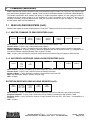
MODBUS-RTU Applied
to the TempTrac® Control
BOILER
ELECTRONIC CONTROLLER
Riverside Hydronics®, LLC
WWW.RIVERSIDEHYDRONICS.COM
3220 Galvez Avenue - Fort Worth, Texas 76111 - Tel 1-800-990-5918
34-502
06/2014
Page 1 / 18
Table of Contents
1. THIS MANUAL ............................................................................................................................ 3
2. MODBUS RTU: ........................................................................................................................... 3
2.1 OVERVIEW: ........................................................................................................................... 3
2.1.1 DEFINITIONS: ........................................................................................................... 3
2.2 COMMUNICATION DETAILS: ............................................................................................... 4
2.2.1 Normal Communication diagram ............................................................................... 5
2.2.2 Communication with exception code ......................................................................... 5
2.3 SEQUENCE OF MODBUS RTU COMMAND AND RESPONSE: ......................................... 5
3. COMMANDS (MESSAGES) ....................................................................................................... 6
3.1 READ HOLDING REGISTERS (0x03): ................................................................................. 6
3.1.1 MASTER COMMAND TO READ REGISTERS (0x03): ............................................. 6
3.1.2 SUCCESSFUL RESPONSE, READ HOLDING REGISTERS (0x03): ...................... 6
EXCEPTION RESPONSE, READ HOLDING REGISTER (0x03): ....................................... 6
3.2 WRITE SINGLE REGISTER (0X06): ..................................................................................... 7
3.2.1 MASTER COMMAND TO WRITE SINGLE REGISTER (0x06): ............................... 7
3.2.2 SUCCESSFUL RESPONSE FROM WRITE SINGLE REGISTER (0x06) ................ 7
3.2.3 EXCEPTION RESPONSE FROM WRITE SINGLE REGISTER (0x06): ................... 7
3.3 WRITE HOLDING REGISTERS (0x10): ................................................................................ 8
3.3.1 MASTER COMMAND TO WRITE HOLDING REGISTER (0x10): ............................ 8
3.3.2 SUCCESSFUL RESPONSE FROM WRITE HOLDING REGISTERS (0x10): .......... 8
EXCEPTION RESPONSE FROM WRITE HOLDING REGISTERS (0x10): ......................... 8
3.4 EXCEPTION RESPONSE: .................................................................................................... 9
4. TEMPTRAC® REGISTERS ......................................................................................................... 10
4.1 LIST OF REGISTERS IN THE TEMPTRAC® ........................................................................ 10
4.2 TYPICAL PARAMETERS FOR ACCESS OVER MODBUS:................................................. 15
5. SERIAL CONFIGURATION ........................................................................................................ 16
5.1 PORT SETUP ........................................................................................................................ 16
6. WIRING ....................................................................................................................................... 16
6.1 TYPICAL WIRING DETAIL .................................................................................................... 16
6.2 PROPER WIRING EXAMPLE ............................................................................................... 17
6.3 IMPROPER WIRING EXAMPLE ........................................................................................... 17
6.4 LINE TERMINATION (LT) ...................................................................................................... 17
6.5 LINE BIASING........................................................................................................................ 17
6.6 SERIAL INTERFACE XJ485.................................................................................................. 17
7. REFERENCES ............................................................................................................................ 18
7.1.1 MODBUS INFORMATION: ........................................................................................ 18
7.1.2 APPLICATION DETAILS AND SENSOR LOCATIONS: ........................................... 18
7.1.3 TEMPTRAC® FEATURES: ........................................................................................ 18
7.1.4 MORE INFORMATION: ............................................................................................. 18
Riverside Hydronics®, LLC
WWW.RIVERSIDEHYDRONICS.COM
3220 Galvez Avenue - Fort Worth, Texas 76111 - Tel 1-800-990-5918
34-502
06/2014
Page 2 / 18
1.
THIS MANUAL
This is a supplemental manual to cover the communication interface capabilities of the TempTrac® thermostatic
module using Modbus RTU. This manual will provide the particulars for the TempTrac®, how the Modbus RTU
protocol is implemented on the TempTrac®, and how to interface with the TempTrac®. For details on how to operate
or configure the TempTrac®, please refer to the TempTrac® Manual (34-81).
This manual is not a complete or definitive guide to Modbus RTU communication. For detailed MODBUS and Modbus
RTU information, consult other sources such as (www.modbus.org).
2.
MODBUS RTU:
2.1 OVERVIEW:
Modbus RTU This is a communication over twisted pair from a Master device (also called a client) to multiple slave
devices (also called servers). The master will send command to a particular slave. The slave will in turn process this
command and respond to the Master. All communication is initiated by the Master. The TempTrac® is a slave device
and will not “talk” until a Master device talks to it first. Modbus RTU is widely used within Building Management
Systems (BMS) and Industrial Automation Systems (IAS). This wide acceptance is due in large part to Modbus RTU’s
ease of use. Modbus RTU is a low level communications that contain no unit type, data scaling, or data description.
Simply put, it is a list of addresses that can be read and/or written to. The type of data will have to be known by the
receiving device in order for the data to be useful. Data types and available registers are usually provided as device
documentation register list.
2.1.1 DEFINITIONS:
MODBUS Protocol: A messaging structure used for communication between devices, machines, sensors, and/or
computers.
Modbus-RTU: (Remote Terminal Unit) Implementation of the Modbus protocol on top of a serial line with an RS232, RS-485 or similar physical layer. The TempTrac® uses 2-wire RS-485 Physical Layer and implements Modbus
RTU.
Master Device:Also known as Client, this device initiates all communication on the RS-485 network. The Master will
send commands to Slave Devices.
Slave Device:Also known as Server, this device will respond only when addressed by the Master device. When the
Master sends the slave a command, it will perform the command and respond back to the Master with the data
requested, or if no data is required, then it will simply echo the command.
Slave Address:Each slave device in a network is assigned a unique address from 1 to 247. When the Master
requests data, the first byte it sends is the Slave address. This way each slave knows after the first byte whether or
not to ignore the message.
RS-485 (EIA-485):A 2 wire (twisted pair) multi drop network. Each device can send data by holding positive and
negative voltage on the line and reversing polarity on the 2 wires. When no devices are transmitting, the line will be
tri-state. The recommended arrangement of the wires is as a connected series of point-to-point (multi-dropped)
nodes, i.e. a line or bus, not a star, ring, or multiply connected network. The number of devices that can be connected
to a single line is defined in the RS-485 standard by the input impedance of 32 UNIT LOADs. The wire and circuits
interfacing on this 2 wire connection is considered the PHYSICAL LAYER. (RS-485 is the same physical layer as
used with BACNET MSTP.)
Riverside Hydronics®, LLC
WWW.RIVERSIDEHYDRONICS.COM
3220 Galvez Avenue - Fort Worth, Texas 76111 - Tel 1-800-990-5918
34-502
06/2014
Page 3 / 18
Line Termination: (LT)On RS-485, ideally the two ends of the cable will have a termination resistor connected
across the two wires. This helps with reducing noise and interference on high speed and long line lengths. In practice,
it is not needed in low speed and short line lengths. When needed, adding a 150ohm resistor across the line at the
end devices will reduce electrical noise and reflections.
Biasing Resistors:One device on the RS-485 line should have biasing resistors. This holds the line in a known state
when no devices are transmitting (talking). Typically this would be the Master device.
TempTrac® Implementation:Modbus RTU protocol, over RS-485 (EIA-485) physical layer using 2 wires. Each
TempTrac® should be considers 1 UNIT LOAD for the network loading. The TempTrac® device do not have biasing
resistors. TempTrac® will operate in slave mode and will only transmit when addressed by the Master device.
Registers: ( Holding Registers )Each Register is 1 word defined as 2 bytes or 16 bits. See Table 2 for details of
each Register. Holding registers are typically READ/WRITE but can be READ ONLY or WRITE ONLY. The
TempTrac® uses only this type of register. All Registers are in the range of 40001-4999.
Register Numbers / Register Addresses:Modbus can be confusing when referencing registers and their addresses.
Modbus documentation is not consistent and terms are used interchangeably when they have different meanings.
Register Addresses always start at 0 and count up, and Register Numbers are the actual number/name of the
Register. Example the first Holding Register is 40001. This would be address 0. For each data type, the address
would start at 0 again. To avoid confusion, this manual will reference Register Numbers only. Any reference to a
Register less than 40000 simply needs the 40000 added to it. Setpoint ST1 is Register 769 or the actual Register
Number 40769. For a list of all available registers, see Table 2 Input Registers, Discrete Inputs and
Coils:MODBUS defines several types of data. The only data used by the TempTrac® is the Holding Register (40001
– 49999). The TempTrac® does not use Input Registers, Discrete Inputs or Coils.
CRC ERROR CHECKING:Modbus-RTU includes an error-checking field that is based on a Cyclical Redundancy
Checking (CRC) method performed on the message contents. The CRC field checks the contents of the entire
message. The CRC field contains a 16-bit value as the last 2 bytes in any message. The low-order byte of the field is
appended first, followed by the high-order byte. The CRC value is calculated by the sending device, which appends
the CRC to the message. The receiving device recalculated a CRC during receipt of the message, and compares the
calculated value to the actual value it received in the CRC field. If the two values are not equal, the message will be
ignored. Most Energy Management software packages will automatically calculate the CRC values as a normal part
of the protocol.
2.2 COMMUNICATION DETAILS:
The MODBUS application data unit is built by the Master (client) that initiates a MODBUS transaction. The function
indicates to the slave (server) what kind of action to perform. The function code field of a MODBUS data unit is coded
in one byte. When a message is sent from a Master to a Slave device the function code field tells the Slave what kind
of action to perform. The message contains information that the Slave uses to take the action defined by the function
code. If no error occurs in receiving the message from the Master, the slave will respond to the Master. The response
(Slave to Master) message contains the data requested, if no data was requested, it will echo the Master’s command.
See Figure 1 for a diagram of a successful communication. If the slave is unable to execute the command (example:
invalid command, unreachable address), the message contains an error code and an exception code. See Figure 2
for diagram of an exception response. See Table 1 for a list of exception codes.
Riverside Hydronics®, LLC
WWW.RIVERSIDEHYDRONICS.COM
3220 Galvez Avenue - Fort Worth, Texas 76111 - Tel 1-800-990-5918
34-502
06/2014
Page 4 / 18
2.2.1 Normal Communication diagram
Master
Slave
Initiate Request
Function Code
Data Request
Perform the action
Initiate the response
Function Code
Data Response
Receive the Response
Figure 1
MODBUS Transaction (Error Free)
2.2.2 Communication with exception code
Master
Slave
Initiate Request
Function Code
Data Request
Error detected in the
packet, initiate an error
Error Code
Exception Code
Receive the response
Figure 2
MODBUS Transaction (Error, Exception Code response)
2.3 SEQUENCE OF MODBUS RTU COMMAND AND RESPONSE:
1) Master (Automation System) Sends command to Slave devices (TempTrac®)
2) After transmitting, the Master turns off the line driver and listens
3) All Slave Devices receives command. (They are in listen mode)
a) If address matches Slave address and the CRC is valid, that Slave will process command.
i) If command was successfully processed
(1) Slave responds with its own slave address, and echoes the command it received, and includes any
data that may have been requested by the Master.
(2) After sending, the Slave goes back to listen mode.
ii) If command was not successfully processed
(1) Slave will respond with and exception response and exception code indicating why it was not
processed.
(a) Possible caused would be invalid address. See Table 1 Exception Codes
(2) After sending, The Slave goes back to listen mode.
b) If the command received fails the CRC validation, no response is given.
c) If the command received does not match the Slave address, no response is given.
d) If the command is incomplete, no response is given.
e) If no command is received, no response is given.
Riverside Hydronics®, LLC
WWW.RIVERSIDEHYDRONICS.COM
3220 Galvez Avenue - Fort Worth, Texas 76111 - Tel 1-800-990-5918
34-502
06/2014
Page 5 / 18
3.
COMMANDS (MESSAGES)
Modbus standard has several commands used to access different types of data. The TempTrac® only uses the data
type called Holding Registers (40001 – 49999). There are only 3 commands needed to access the Holding Registers.
The Modbus specification allow reading and writing to multiple sequential registers, but the maximum number of
registers that can be read or written to in one command is 5, this is a limitation of the TempTrac® device. In the
following commands, the actual address will be used, the command indicates the type of register it is. For example,
the first register 40001 will have address 0.
3.1 READ HOLDING REGISTERS (0x03):
Read a single register or multiple registers from the TempTrac®. Response will be the values stored in the registers.
3.1.1 MASTER COMMAND TO READ REGISTERS (0x03):
Slave
Address
Function
Code 0x03
Register
Address
(MSByte)
Register
Address
(LSByte)
Number of
Registers
(MSByte)
Number of
Registers
(LSByte)
CRC
(LSByte)
CRC
(MSByte)
Slave Address: (1 byte): Device address that receives the command. Range: 1-247.
Function Code: (1 byte): Code = 0x03 (Read holding register).
Register Address: (2 bytes): The address of the first register to be read, reading multiple registers is sequential.
Number of Registers: (2 bytes): Number of Elements (Registers) that the device has to return (3 = 3 Registers). No
more than 5 Elements (registers) allowed. (Each register is 16 bits).
CRC: (2 bytes): CRC calculated for the frame data received and is used to verify the integrity of data received.
3.1.2 SUCCESSFUL RESPONSE, READ HOLDING REGISTERS (0x03):
Slave
Address
Success
echo:
Code
0x03
Number
of
Bytes
Data 1
Data …
Data
n
CRC
(LSByte)
CRC
(MSByte)
Slave Address: (1 byte): The address of the slave responding. Same as the address in the initiating command.
Function Code: (1 byte): Code = 0x03 Echo from the initiating command.
Number of Bytes: (1 byte): Defines the number of bytes followed minus the CRC.
Data: Byte data buffer, length is “Number of Bytes” long.
CRC: (2 bytes):
EXCEPTION RESPONSE, READ HOLDING REGISTER (0x03):
Slave
Address
Exception
0x03 + 0x80
Error: 0x83
Exception
Code
see list
CRC
(LSByte)
CRC
(MSByte)
Slave Address: (1 byte): The address of the slave responding. Same as the address in the initiating command.
Exception Response: (1 byte): Code = 0x03 Echo from the initiating command plus high bit 0x80 = 0x83.
Exception Code: (1 byte): Defines the number of bytes followed minus the CRC. See Table 1 for explanation of
exceptions.
CRC: (2 bytes):
Riverside Hydronics®, LLC
WWW.RIVERSIDEHYDRONICS.COM
3220 Galvez Avenue - Fort Worth, Texas 76111 - Tel 1-800-990-5918
34-502
06/2014
Page 6 / 18
3.2 WRITE SINGLE REGISTER (0X06):
Command to write a value to a single register. Response will be the data written.
3.2.1 MASTER COMMAND TO WRITE SINGLE REGISTER (0x06):
Slave
Address
Function
Code 0x06
Register
Address
(MSByte)
Register
Address
(LSByte)
Data
(MSByte)
Data
(LSByte)
CRC
(LSByte)
CRC
(MSByte)
Slave Address: (1 byte): Device address that receives the command. Range: 1-247.
Function Code: (1 byte): Code = 0x06 (Write single register).
Register Address: (2 bytes): The address of the register to be written to.
Data: (2 bytes): The data to write.
CRC: (2 bytes): CRC calculated for the frame data received and has to be used to verify the integrity of data
received.
3.2.2 SUCCESSFUL RESPONSE FROM WRITE SINGLE REGISTER (0x06)
Slave
Address
Success:
Code 0x06
Register
Address
(MSByte)
Register
Address
(LSByte)
Data
(MSByte)
Data
(LSByte)
CRC
(LSByte)
CRC
(MSByte)
Slave Address: (1 byte): The address of the slave responding. Same as the address in the initiating command.
Function Code: (1 byte): Code = 0x06 Echo from the initiating command.
Register Address: (2 bytes): The address of the register that was written.
Data: (2 bytes): Byte data buffer, will contain the same data that was sent in initiating command.
CRC: (2 bytes):
3.2.3 EXCEPTION RESPONSE FROM WRITE SINGLE REGISTER (0x06):
Slave
Address
Exception
0x06 + 0x80
Error: 0x86
Exception
Code
see list
CRC
(LSByte)
CRC
(MSByte)
Slave Address: (1 byte): The address of the slave responding. Same as the address in the initiating command.
Exception Response: (1 byte): Code = 0x06 Echo from the initiating command plus high bit 0x80 = 0x86.
Exception Code: (1 byte): Defines the number of bytes followed minus the CRC. See Table 1 for explanation of
exceptions.
CRC: (2 bytes):
Riverside Hydronics®, LLC
WWW.RIVERSIDEHYDRONICS.COM
3220 Galvez Avenue - Fort Worth, Texas 76111 - Tel 1-800-990-5918
34-502
06/2014
Page 7 / 18
3.3 WRITE HOLDING REGISTERS (0x10):
Command to write 1-5 registers. Limit is 5 registers. Response will be the number of registers written.
3.3.1 MASTER COMMAND TO WRITE HOLDING REGISTER (0x10):
Slave
Address
Function
Code 0x10
Register
Address
(MSByte)
Register
Address
(LSByte)
Number
Registers
(MSByte)
Number
Registers
(LSByte)
Num
Byte
Data
CRC
(LSByte)
CRC
(MSByte)
Slave Address: (1 byte): Device address that receives the command. Range: 1-247.
Function Code: (1 byte): Code = 0x10 (Write holding registers 1-5).
Register Address: The address of the first register to write to.
Number of Registers: (2 bytes): Defines the number of Elements (Registers) to write to. No more than 5 Elements
allowed for the TempTrac®.
Num Byte: (1 byte): Defines the number of bytes followed minus the CRC. The number of bytes has to be double
the number of addressed Elements (Number of bytes = 2 x number of Registers).
Data: (Num Byte or 2 X Number of Registers): Data to be written in MSByte, LSByte order.
CRC: (2 bytes): CRC calculated for the frame data received and has to be used to verify the integrity of data
received.
3.3.2 SUCCESSFUL RESPONSE FROM WRITE HOLDING REGISTERS (0x10):
Slave
Address
Function
Code
0x10
Register
Address
(MSByte)
Register
Address
(LSByte)
Number
Registers
(MSByte)
Number
Registers
(LSByte)
CRC
(LSByte)
CRC
(MSByte)
Slave Address: (1 byte): The address of the slave responding. Same as the address in the initiating command.
Function Code: (1 byte): Code = 0x10 Echo from the initiating command.
Register Address: (2 bytes): The address of the register that was written.
Number Registers: (2 bytes): The number of registers written.
CRC: (2 bytes):
EXCEPTION RESPONSE FROM WRITE HOLDING REGISTERS (0x10):
Slave
Address
Error, Code
0x10 + 0x80
Error: 0x90
Exception
Code, see list
CRC
(LSByte)
CRC
(MSByte)
Slave Address: (1 byte): The address of the slave responding. Same as the address in the initiating command.
Exception Response: (1 byte): Code = 0x10 Echo from the initiating command plus high bit 0x80 = 0x90.
Exception Code: (1 byte): Defines the number of bytes followed minus the CRC. See Table 1 for explanation of
exceptions.
CRC: (2 bytes):
Riverside Hydronics®, LLC
WWW.RIVERSIDEHYDRONICS.COM
3220 Galvez Avenue - Fort Worth, Texas 76111 - Tel 1-800-990-5918
34-502
06/2014
Page 8 / 18
3.4 EXCEPTION RESPONSE:
Exceptions result from a valid packet being received by the Slave device but the slave is unable to complete the
command. This can be the result of an invalid address, or a write command to a read only Register. Table 1 provides
an explanation of each Exception Code and the possible cause.
Table 1
EXCEPTION CODES:
Exception
Code
01
02
03
04
06
Name
Meaning
Illegal Function
The function code received in the query is not an
allowable action for the slave. Only function codes
0x03, 0x06, 0x10 are valid commands.
Illegal Data Address
Illegal Data Value
Slave Device Failure
Slave Device Busy
The data address received in the query is not an
allowable address for the slave. More specifically,
the combination of reference number and transfer
length is invalid.
Requesting a register that does not exist. More
than 5 elements requested. Writing a parameter
out of range. Writing to read only register.
An unrecoverable error occurred while the slave
was attempting to perform the requested action.
The device didn’t succeed in reading or writing
requested operation. Operation (Ram, E2, RTC
and etc) is not completing operation correctly.
The device can’t execute requested operation at
this time. Busy in another analogue operation.
Master has to repeat the same request at another
time.
Riverside Hydronics®, LLC
WWW.RIVERSIDEHYDRONICS.COM
3220 Galvez Avenue - Fort Worth, Texas 76111 - Tel 1-800-990-5918
34-502
06/2014
Page 9 / 18
4.
TEMPTRAC® REGISTERS
4.1 LIST OF REGISTERS IN THE TEMPTRAC®
Table 2
List of registers for the TempTrac® Label is the descriptive text displayed on the TempTrac® or on the terminal labels.
Firm Version refers to Firmware Revision; this can be found on the label on the side of the TempTrac® or in the REL
parameter.
Labe
l
Description
Firm
Range
Rev
0.3
Rev
0.5
Hex Add
Modbus
X÷Y
Level
Level
base 0
Version
Register
40000+
0.3 & 0.5
Set point1
0.3 & 0.5
Set point2
St3
0.3 & 0.5
Set point3
St5
0.3 & 0.5
Set point5 Set point 3 alternate
HY1
0.3 & 0.5
Differential for St1
LS1
0.3 & 0.5
Minimum set point1
US1
0.3 & 0.5
Maximum set point1
AC1
0.3 & 0.5
Anti-short cycle delay for output 1
S2c
0.3 & 0.5
HY2
0.3 & 0.5
Configuration of St2: dependent on St1 or
independent
Differential for St2
0.3 & 0.5
Minimum set point2
uS2
0.3 & 0.5
Maximum set point2
AC2
0.3 & 0.5
Anti-short cycle delay for output 2
S3c
0.3 & 0.5
HY3
0.3 & 0.5
Configuration of St3: dependent on St1 or
independent
Differential for set point 3 St3
LS3
0.3 & 0.5
Minimum set point 3 St3
uS3
0.3 & 0.5
Maximum set point 3 St3
AC3
0.3 & 0.5
Anti-short cycle delay for output 3
0.3 & 0.5
Probe selection for output 3
0.3 & 0.5
Set point shift for output 3 enable disable
0.3 & 0.5
Differential for set point 5
Ac5
0.3 & 0.5
AcA
0.3 & 0.5
Anti-short cycle delay for output 3
alternate set point
Time delay between the St3 to St5 set
point shift
St1
St2
LS2
o3P
SSE
HY5
LS1÷US1
Pr1
Pr1
0x300
769
LS2÷US2
Pr1
Pr1
0x301
770
LS3÷US3
Pr1
Pr1
0x302
771
-20÷70°F
Pr1
Pr1
0x303
772
-22÷22°F
Pr2
Pr2
0x304
773
-40°F÷SET
Pr2
Pr2
0x305
774
SET ÷ 230°F
Pr2
Pr2
0x306
775
776
0÷30 min.
Pr2
Pr2
0x307
diP; ind
Pr3
Pr2
0x308
777
-22÷22°F
Pr2
Pr2
0x309
778
-40°F÷St2
Pr2
Pr2
0x30A
779
St2 ÷ 230°F
Pr2
Pr2
0x30B
780
0÷30 min.
Pr2
Pr2
0x30C
781
diP; ind
Pr2
Pr2
0x30D
782
-22÷22°F
Pr2
Pr2
0x30E
783
-40°F÷St3
Pr2
Pr2
0x30F
784
St3 ÷ 230°F
Pr2
Pr2
0x310
785
786
0÷30 min.
Pr2
Pr2
0x311
Pb1 / Pb2
Pr2
Pr2
0x312
787
No; Yes
Pr2
Pr2
0x313
788
-22÷22°F
Pr2
Pr2
0x314
789
0÷30 min.
Pr2
Pr2
0x315
790
0÷15 min.
Pr2
Pr2
0x316
791
diP; ind
Pr3
Pr2
0x317
792
-100÷100°F
Pr2
Pr2
0x318
793
-100÷100°F
Pr2
Pr2
0x319
794
-40°F ÷ 230°F
Pr2
Pr2
0x31A
795
-45 ÷ -1 °F
Pr2
Pr2
0x31B
796
0÷30 min.
Pr2
Pr2
0x31C
797
ANALOGUE OUTPUT 4÷20mA (output 4)
S4c
0.3 & 0.5
St4
0.3 & 0.5
Configuration of St4: dependent on St1 or
independent
Analogue output set point
SR
0.3 & 0.5
Analogue output band width
Th4
0.3 & 0.5
HY4
0.3 & 0.5
Ac4
0.3 & 0.5
Outlet temperature threshold for forcing
to 4ma the analog output
Differential for restart working of analog
output
Anti-short cycle delay for output 4
Riverside Hydronics®, LLC
WWW.RIVERSIDEHYDRONICS.COM
3220 Galvez Avenue - Fort Worth, Texas 76111 - Tel 1-800-990-5918
34-502
06/2014
Page 10 / 18
PS4
PP4
0.3 & 0.5
Analog output percentage (nu=101)
0.3 & 0.5
Analog output percentage with fault
probe 1 (nu=101)
0÷100, nu
Pr2
Pr2
0x31D
798
0÷100, nu
Pr3
Pr2
0x31E
799
-40÷230°F
Pr2
Pr2
0x31F
800
-100÷100°F
Pr2
Pr2
0x320
801
-100÷100°F
Pr2
Pr2
0x321
802
-40÷230°F
Pr2
Pr2
0x322
803
-45 ÷ -1 °F
Pr2
Pr2
0x323
804
CL÷OP
Pr3
Pr2
0x324
805
CL÷OP
Pr2
Pr2
0x325
806
0÷255 min.
Pr3
Pr2
0x326
807
CL÷OP
Pr2
Pr2
0x327
808
809
DYNAMIC RESET
tt
0.3 & 0.5
rr2
0.3 & 0.5
Outdoor temperature threshold
dynamic reset of St1
Outdoor temperature band width
0.3 & 0.5
Maximum shift of St1
tt2
0.3 & 0.5
Ht2
0.3 & 0.5
Outdoor temperature threshold to open
all the loads
Differential for restart working of
controller
rr1
for
DIGITAL INPUTS
i1P
0.3 & 0.5
Digital input 1 polarity
i2P
0.3 & 0.5
Digital input 2 polarity
i2d
0.3 & 0.5
Digital input 2 alarm delay
i3P
0.3 & 0.5
Digital input 3 polarity
i3d
0.3 & 0.5
Digital input 3 alarm delay
0÷255 min.
Pr3
Pr2
0x328
°C ÷ °F
Pr3
Pr2
0x329
810
in ÷ de
Pr3
Pr2
0x32A
811
Pb2, Pb3
Pr2
0x32B
812
0x32B
812
0x32C
813
Pr2
0x32C
813
DISPLAY
0.3 & 0.5
Temperature measurement unit
rES
0.3 & 0.5
dS2
0.3
Resolution (integer/decimal point) only
for °C
Default showing for display #2 Top (red)
cF
dS2
0.5
dS1
0.3
dS1
0.5
Default showing for display #2 Top (red)
Pb3 will display yellow EXT, Ani will
display yellow Valve/M
Default showing for display #1 Bottom
(Yellow)
Default showing for display #1 Bottom
(Yellow) Pb3 will display yellow EXT, Ani
will display yellow Valve/M
Pb1,Pb2,Pb3,AnI
Pb1; tiM
Pr2
Pr2
Pb1,Pb2,Pb3,AnI, TiM
ALARMS
Alc
0.3 & 0.5
ALL
0.3
ALL
0.5
Alu
0.3
Alu
0.5
AFH
0.3 & 0.5
ALd
0.3 & 0.5
dAo
0.3 & 0.5
Temperature
alarms
configuration:
dependent on St1 or independent
minimum temperature alarm for Pb1
(Alarm LA flash only)
minimum temperature alarm for Pb1
(Alarm LA flash and signal on 3329)
MAXIMUM temperature alarm for Pb1
(Alarm HA flash only)
MAXIMUM temperature alarm for Pb1
(Alarm HA flash and signal on 3329)
Differential for temperature
recovery
Temperature alarm delay
rE÷Ab
Pr3
Pr2
0x32D
814
-40÷230°F
Pr2
Pr2
0x32E
815
-40÷230°F
Pr2
Pr2
0x32E
815
-40÷230°F
Pr3
Pr2
0x32F
816
-40÷230°F
Pr3
Pr2
0x32F
816
1÷45°F
Pr2
Pr2
0x330
817
0÷255 min.
Pr2
Pr2
0x331
818
0 ÷ 23h 50 min.
Pr2
Pr2
0x332
819
-21÷21°F
Pr3
Pr2
0x333
820
No; Yes
Pr2
Pr2
0x334
821
-21÷21°F
Pr3
Pr2
0x335
822
Pr2
0x336
823
alarm
Delay of temperature alarm at start up 1 =
10 min disp 0.1
ANALOGUE INPUTS
oF1
0.3 & 0.5
First probe calibration
P2P
0.3 & 0.5
Second probe presence
oF2
0.3 & 0.5
Second probe calibration
P3P
0.3 & 0.5
Third probe presence
No; Yes
Pr2
Riverside Hydronics®, LLC
WWW.RIVERSIDEHYDRONICS.COM
3220 Galvez Avenue - Fort Worth, Texas 76111 - Tel 1-800-990-5918
34-502
06/2014
Page 11 / 18
oF3
0.3 & 0.5
Third probe calibration
-21÷21°F
Pr3
Pr2
0x337
824
TIME AND DATE
Hur
Min
dAY
0.3 & 0.5
Current hour
0.3 & 0.5
Current minute
0.3 & 0.5
Current day
0 ÷ 23
Pr2
Pr2
0x338
825
0 ÷ 59
Pr2
Pr2
0x339
826
Sun ÷ SAt
Pr2
Pr2
0x33A
827
0 ÷ 23h 50 min. - nu
Pr2
Pr2
0x33B
828
0 ÷ 23h 50 min. - nu
Pr2
Pr2
0x33C
829
-40÷40°F
Pr2
Pr2
0x33D
830
831
ENERGY SAVING TIMES
E1
0.3 & 0.5
Energy saving start on Sunday
S1
0.3 & 0.5
Energy saving stop on Sunday
Sb1
0.3 & 0.5
Set back temperature on Sunday
E2
0.3 & 0.5
Energy saving start on Monday
S2
0.3 & 0.5
Energy saving stop on Monday
0.3 & 0.5
Set back temperature on Monday
E3
0.3 & 0.5
Energy saving start on Tuesday
S3
0.3 & 0.5
Energy saving stop on Tuesday
Sb3
0.3 & 0.5
Set back temperature on Tuesday
E4
0.3 & 0.5
Energy saving start on Wednesday
S4
0.3 & 0.5
Energy saving stop on Wednesday
Sb4
0.3 & 0.5
Set back temperature on Wednesday
0.3 & 0.5
Energy saving start on Thursday
0.3 & 0.5
Energy saving stop on Thursday
Sb5
0.3 & 0.5
Set back temperature on Thursday
E6
0.3 & 0.5
Energy saving start on Friday
S6
0.3 & 0.5
Energy saving stop on Friday
Sb6
0.3 & 0.5
Set back temperature on Friday
E7
0.3 & 0.5
Energy saving start on Saturday
S7
0.3 & 0.5
Energy saving stop on Saturday
Sb7
0.3 & 0.5
Set back temperature on Saturday
Sb2
E5
S5
0 ÷ 23h 50 min. - nu
Pr2
Pr2
0x33E
0 ÷ 23h 50 min. - nu
Pr2
Pr2
0x33F
832
-40÷40°F
Pr2
Pr2
0x340
833
0 ÷ 23h 50 min. - nu
Pr2
Pr2
0x341
834
0 ÷ 23h 50 min. - nu
Pr2
Pr2
0x342
835
-40÷40°F
Pr2
Pr2
0x343
836
0 ÷ 23h 50 min. - nu
Pr2
Pr2
0x344
837
0 ÷ 23h 50 min. - nu
Pr2
Pr2
0x345
838
839
-40÷40°F
Pr2
Pr2
0x346
0 ÷ 23h 50 min. - nu
Pr2
Pr2
0x347
840
0 ÷ 23h 50 min. - nu
Pr2
Pr2
0x348
841
-40÷40°F
Pr2
Pr2
0x349
842
0 ÷ 23h 50 min. - nu
Pr2
Pr2
0x34A
843
0 ÷ 23h 50 min. - nu
Pr2
Pr2
0x34B
844
-40÷40°F
Pr2
Pr2
0x34C
845
0 ÷ 23h 50 min. - nu
Pr2
Pr2
0x34D
846
847
0 ÷ 23h 50 min. - nu
Pr2
Pr2
0x34E
-40÷40°F
Pr2
Pr2
0x34F
848
0÷9999 Hours
Pr1
Pr2
0x350
849
0÷9999 Hours
Pr1
Pr2
0x351
850
0÷9999 Hours
Pr2
Pr2
0x352
851
0÷9999, 0=disabled
Pr2
Pr2
0x353
852
0÷9999, 0=disabled
Pr2
Pr2
0x354
853
0÷9999, 0=disabled
Pr2
Pr2
0x355
854
rEG=2; on=1; oFF=0
Pr2
Pr2
0x356
855
rEG=2; on=1; oFF=0
Pr2
Pr2
0x357
856
rEG=2; on=1; oFF=0
Pr2
Pr2
0x358
857
WORKING HOURS
ou1
0.3 & 0.5
working hours actual of relay 1
ou2
0.3 & 0.5
working hours actual of relay 2
ou3
0.3 & 0.5
working hours actual of relay 3
oP1
0.3 & 0.5
oP2
0.3 & 0.5
oP3
0.3 & 0.5
working hours limit of relay 1, Nn1 Alarm
when reached
working hours limit of relay 2, Nn2 Alarm
when reached
working hours limit of relay 3, Nn3 Alarm
when reached
OUTPUTS SETTING
1on
0.3 & 0.5
2on
0.3 & 0.5
3on
0.3 & 0.5
The output 1 force ON / OFF or Temperature
regulation
The output 2 force ON / OFF or Temperature
regulation
The output 3 force ON / OFF or Temperature
regulation
Riverside Hydronics®, LLC
WWW.RIVERSIDEHYDRONICS.COM
3220 Galvez Avenue - Fort Worth, Texas 76111 - Tel 1-800-990-5918
34-502
06/2014
Page 12 / 18
OTHER
0.3 & 0.5
Serial address
0.3 & 0.5
Parameter map code always = 1
rEL
0.3 & 0.5
Software release 5 = V0.5, 3 = V0.3
i1S
0.5
Analog output when Digital Input 1 is activated
i1t
0.5
Analog output at i1S extra time if Digital Input 1
is not activated
i1d
0.5
Digital Input 1 Alarm Delay
0.5
If Yes, Digital Input 1 will function as Alarm.
Operating only when trying to call for output 1
and Input 1 is active, subject to i1d timer
Adr
Ptb
i1F
i2F
0.5
i3F
0.5
oS2
0.5
(TP1)
0.3 & 0.5
0.3
(TP2)
0.3 & 0.5
0.3
(TP3)
0.3 & 0.5
0.3
0.5
0.3 & 0.5
0.3
0.3
0.3
0.5
0.5
0.5
0.5
0.5
0.5
Digital Input 2 will function only when Output 1
is energized
Digital Input 3 will function only when Output 1
is energized, When Edi is selected, Output 1 will
open when digital input 3 is activated
Output 2 function: either temp relay or alarm
relay
Probe 1 temperature
Probe 1 Information/Status Normal=512 or
0x0200, Fault=515 or 0x0203. Fault will, drop
call for heat, buz, Flash Yellow P1, light yellow
valve/M
Probe 2 temperature
Probe 2 Information/Status Normal=512 or
0x0200, Fault=515 or 0x0203. Fault will buz,
Flash Red P2
Probe 3 temperature
Probe 3 Information/Status Normal=512 or
0x0200, Fault=515 or 0x0203. Fault will buz,
Flash Red P3
Modulation rate output (4 to 20mA)
Statas of Relay 1,2&3
Input 3 Alarm, buz, ALMMB, Flashes HP= 4096
or 0x0800
Input 2 Alarm, buz, Flashes LP= 4096 or 0x0800
Input 2 & 3, buz, Flashed HP & LP= 4096 or
0X0800
Low Temperature Alarm, beep, Flash Yellow
LA= 1 or 0x0001
High Temperature Alarm, beep, Flash yellow
HA= 2 or 0x0002
Probe 1 error, open or shorted, Drops call for
heat, yel valve/M on, Flash Yellow P1=4 or
0x0004
Probe 2 error, open or shorted, Flashing red
P2=256 or 0x0100
Probe 3 error, open or shorted, Flashing red
P3=512 or 0x0200
ALARM 1 (stops heating) Input 1, beep, Flash
AL1 = 1024 or 0x0400. Will recover if Input 1
goes away, or need for call for heat goes away.
0÷247
Pr2
Pr2
0x359
858
readable only
Pr2
Pr2
0x35A
859
readable only
Pr2
Pr2
0x35B
860
4-20mA
Pr2
0x35C
861
0÷30 sec.
Pr2
0x35D
862
0÷255 min.
Pr2
0x35E
863
No; Yes
Pr2
0x35F
864
No; Yes
Pr2
0x360
865
No; Yes; Edi
Pr2
0x361
866
Std; AL
Pr2
0x362
867
Degrees F/C
Pr2
0x100
257
bit (0,1 on) probe
failure
Pr2
0x101
258
Degrees F/C
Pr2
0x102
259
bit (0,1 on) probe
failure
Pr2
0x103
260
Degrees F/C
Pr2
0x104
261
bit (0,1 on) probe
failure
Pr2
0x105
262
0÷100%
Pr2
0x106
263
bit 0,1,2
Pr2
0x801
2050
bit # 12 or 13th bit
Pr2
0xD00
3329
bit # 12 or 13th bit
Pr2
0xD00
3329
bit # 12 or 13th bit
Pr2
0xD00
3329
bit # 0 or 1st bit
Pr2
0xD00
3329
bit # 1 or 2nd bit
Pr2
0xD00
3329
bit # 2 or 3rd bit
Pr2
0xD00
3329
bit # 8 or 9th bit
Pr2
0xD00
3329
bit # 9 or 10th bit
Pr2
0xD00
3329
bit # 10 or 11th bit
Pr2
0xD00
3329
34-502
06/2014
Riverside Hydronics®, LLC
WWW.RIVERSIDEHYDRONICS.COM
3220 Galvez Avenue - Fort Worth, Texas 76111 - Tel 1-800-990-5918
Page 13 / 18
0.5
0.5
0.5
0.5
0.5
0.3 & 0.5
0.3 & 0.5
0.3 & 0.5
ALARM 2 (Lockout, stops heating) Input 2, Flash
AL2 & Lguage & valve= 2048 or 0x1000
ALARM 3 (Lockout, stops heating) Input
3/ALMMB/ALOAF, beep, Flash AL3 & Hguage &
valve (This is ALARM ON ANY FAILURE)= 4096 or
0x0800
Maintenance Relay1, beep, Flash Nn1 &
wrench=8192 or 0x2000 You must reset hours
ou1 or set oP1=0
Maintenance Relay2, beep, Flash Nn2 &
wrench=16384 or 0x4000 You must reset hours
ou2 or set oP2=0
Maintenance Relay3, beep, Flash Nn3 &
wrench=32768 or 0x8000 You must reset hours
ou3 or set oP3=0
On/Off On=257 or 0x0101, Off=1 or 0x0001 Can
be used to reset ALMMB alarm by cycling OFF,
wait 30 sec , ON
Keyboard Lock Lock=2056 or 0x0808, Unlock=8
or 0x0008. If locked PoF is displayed when
keypad edit is attempted.
Reset audible alarm when condition is
corrected, 4112 or 0x1010 does not reset
alarm, just stops the beeping
bit # 11 or 12th bit
Pr2
0xD00
3329
bit # 12 or 13th bit
Pr2
0xD00
3329
bit # 13 or 14th bit
Pr2
0xD00
3329
bit # 14 or 15th bit
Pr2
0xD00
3329
bit # 15 or 16th bit
Low byte is mask, Hi
byte is command. Bit
# 0 & #8
Low byte is mask, Hi
byte is command. Bit
# 3 & #11
Low byte is mask, Hi
byte is command. Bit
# 3 & #12
Pr2
0xD00
3329
Pr2
0x500
1281
Pr2
0x500
1281
Pr2
0x500
1281
34-502
06/2014
Energy Savings Registers are enumerated 0 to
145 w/145=n/u
10 min each with 145=nu
All other enumerations start at 0 and count up
Riverside Hydronics®, LLC
WWW.RIVERSIDEHYDRONICS.COM
3220 Galvez Avenue - Fort Worth, Texas 76111 - Tel 1-800-990-5918
Page 14 / 18
4.2 TYPICAL PARAMETERS FOR ACCESS OVER MODBUS:
Setpoint: Modbus Register 40769
St1 Set point1,
This is the typical system setpoint. Read/Write
Working Hours of Burner: Modbus Register 40849
ou1 working hours actual of relay 1 0÷9999 Hours
Number of hours the burner has been on. Rolls over at 9999. Read/Write
Modbus network ID or Address. Modbus Register 40858
Adr Serial address 0÷247
This is the Modbus address. You should configure this with the keypad.
Temperature of Probes: Modbus Registers 40257, 40259, 40261
(TP1) Probe 1 temperature
Degrees F (40257)
Temperature of probe #1. (Terminals 14 & 17) This is the operating probe that ST1 references. Read only
(TP2) Probe 2 temperature
Degrees F (40259)
Temperature of probe #2. (Terminals 15 & 17) Probe use and location varies by job. Reading this will return
exception if probe is disabled. Read only
(TP3) Probe 3 temperature
Degrees F (40261)
Temperature of probe #3. (Terminals 16 & 17) Probe use and location varies by job. Reading this will return
exception if probe is disabled. Read only
Modulation output rate: Modbus Register 40263
Modulation rate output (4 to 20mA)
0÷100%
This parameter does not have a Label. It is the modulation rate. Note that Low Fire is 0, and High Fire is 100% on
most devices.
Output Relays (Burner ON): Modbus Register 42050
Statas of Relay 1,2&3 bit 0,1,2 42050 Relay 1, (Bit 0) is the signal for burner ON.
Relay 2 & 3 are used in special applications.
Alarms: Modbus Register 43329
Alarms are contained in Register bits
Typically you will want to monitor the Alarm on any Failure:
ALARM ON ANY FAILURE
ALARM 3 (Lockout, stops heating)
Input 3 , beep, Flash AL3
The value in the register = 4096 or 0x0800, or bit # 12
Some boilers may use ALARM 2 for ALARM ON ANY FAILURE
ALARM 2 (Lockout, stops heating)
Input 2, Flash AL2
The value in the register = 2048 or 0x1000 bit # 11
Other alarms to monitor:
Probe 1 error, open or shorted,
The value in the register = 4 or 0x0004, or bit # 2
Probe 2 error, open or shorted,
The value in the register = 256 or 0x0100, or bit # 8
Probe 3 error, open or shorted,
The value in the register = 512 or 0x0200, or bit # 9
Riverside Hydronics®, LLC
WWW.RIVERSIDEHYDRONICS.COM
3220 Galvez Avenue - Fort Worth, Texas 76111 - Tel 1-800-990-5918
34-502
06/2014
Page 15 / 18
CONTROL, ON/OFF (Enable/Disable) Modbus Register 41281
It has many functions that are obtained by sending a combination of bits. The only command you need is the
ON/OFF.
ON=257 or 0x0101, OFF=1 or 0x0001
In the OFF state, no heating signal will be present, no alarms, all relay outputs are open, and no temperature are
displayed. The display will show the word “OFF”. It is still possible to read the probe temperatures and other
parameters over Modbus.
This is a write only register. Reading this register will provide invalid results.
5.
SERIAL CONFIGURATION
5.1 PORT SETUP
Baud Rate:9600bps (Not adjustable)
Data Length:8 bit
(Not adjustable)
Parity:None (Not adjustable)
Stop Bits1
(Not adjustable)
Start/Stop:Silent interval of 3 characters minimum
Minimum Time Between Retry:500 msec
6.
WIRING
Modbus RTU uses the same wiring practice and wire as BACNET MSTP.
6.1 TYPICAL WIRING DETAIL
Master
BIAS
(-) (+)
CONNECT GND/SHIELD AT EACH
DEVICE. NO CONNECT AT END
GND
2-WIRE TWISTED
SHIELD, OPTIONAL
COMMON / SHIELD
LT
LT
TXD0 & RXD0, ATA(A)TXD1 & RXD1, DATA(B)+
XJ485 SERIAL INTERFACE
TempTrac
TempTrac
Figure
3Wiring
of
a
typical
Modbus
RTU
network
with
Riverside Hydronics®, LLC
WWW.RIVERSIDEHYDRONICS.COM
3220 Galvez Avenue - Fort Worth, Texas 76111 - Tel 1-800-990-5918
TempTrac®
34-502
devices
06/2014
Page 16 / 18
DEVICE 4
TempTrac
DEVICE 3
TempTrac
DEVICE 2
TempTrac
MASTER
(CLIENT)
DEVICE 1
TempTrac
6.2 PROPER WIRING EXAMPLE
Figure 4 Correctly wired RS-485 Daisy Chain
DEVICE 4
TempTrac
MASTER
(CLIENT)
DEVICE 3
TempTrac
DEVICE 2
TempTrac
DEVICE 1
TempTrac
6.3 IMPROPER WIRING EXAMPLE
Figure 5 Wiring is not correct. Not a daisy chain and the master is not at an end.
6.4 LINE TERMINATION (LT)
Termination resistors are only required on very long cable runs. A reflection in a transmission line is the result of an
impedance discontinuity that a travelling wave sees as it propagates down the line. To minimize the reflections from
the end of the RS485-cable, place a Line Termination near each of the 2 ends of the Bus. It is important that the line
be terminated at both ends since the propagation is bi-directional, but it is not allowed to place more than 2 LTs on
one passive balanced pair.
• Each line termination must be connected between the two conductors of the balanced line: D0 and D1.
• Line termination may be a 150 ohms value (0.5 W) resistor.
• With cable lengths less than 2000’, at 9600 baud, reflection is not an issue and does not require LT resistors.
6.5 LINE BIASING
When there is no data activity on an RS-485 balanced pair, the lines are not driven and thus susceptible to external
noise or interference. To insure the line is in a known state when the line is not active, one or more devices on the
network can provide line biasing by pulling up and down the lines with week resistors. It is common practice for the
Master device to provide line biasing. This is generally a jumper setting on the device. The TempTrac® does not have
line biasing resistors.
• Data(B)+ will be pulled to positive
• Data(A)- will be pulled to negative
6.6 SERIAL INTERFACE XJ485
The XJ485 serial termination is a factory supplied RS485 to TTL connection device. The TempTrac® control comes
standard with a TTL communication port also used as the HOT KEY programming interface. The termination points
are labelled as (+ and –) corresponding to (D1 and D0).
Riverside Hydronics®, LLC
WWW.RIVERSIDEHYDRONICS.COM
3220 Galvez Avenue - Fort Worth, Texas 76111 - Tel 1-800-990-5918
34-502
06/2014
Page 17 / 18
7.
REFERENCES
7.1.1 MODBUS INFORMATION:
This document is not intended to be a comprehensive guide for application or installation of a MODBUS solution. The
following are some additional resources regarding Modbus:
• ANSI/TIA/EIA-232
Interface between data terminal equipment and data circuit-terminating equipment
employing serial binary data interchange.
• ANSI/TIA/EIA-485
Electrical characteristics of generators and receivers for use in balanced digital
multipoint systems.
• MODBUS.org MODBUS applications protocol specification.
7.1.2 APPLICATION DETAILS AND SENSOR LOCATIONS:
The TempTrac® is used in multiple devices with several configurations. Application and configuration information for
the TempTrac® as it is applied to your device can be found in the I & O Manual of the device.
7.1.3 TEMPTRAC® FEATURES:
General features and programing of the TempTrac® can be found in the TempTrac® manual (34-80). Advanced
features can be found in the Advance TempTrac® manual (34-81).
7.1.4 MORE INFORMATION:
For additional information, contact the Riverside Hydronics Customer Service Dept. at 800-990-5918.
Riverside Hydronics®, LLC
WWW.RIVERSIDEHYDRONICS.COM
3220 Galvez Avenue - Fort Worth, Texas 76111 - Tel 1-800-990-5918
34-502
06/2014
Page 18 / 18