1
Universal Power Transducer
USER MANUAL
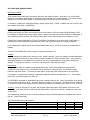
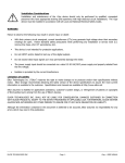
Installation Considerations
Installation and maintenance of the WattsOn meter should only be performed by qualified,
competent personnel who have appropriate training and experience with high voltage and current
devices. The WattsOn meter must be installed in accordance with all Local and National Electrical
Safety Codes.
WARNING
Failure to observe the following may result in severe injury or death:
•
During normal operation of this device, hazardous voltages are present on the input terminal strips of the
device and throughout the connected power lines, including any potential transformers (PTs). With their
primary circuit energized, current transformers (CTs) may generate high voltage when their secondary
windings are open. Follow standard safety precautions while performing any installation or service work
(i.e. remove line/ PT fuses, short CT secondaries, etc).
•
The meter is not intended for protection applications.
•
Do not HIPOT and/or dielectric test any of the digital or analog outputs. Refer to this manual for the
maximum voltage level the meter can withstand.
•
Do not exceed rated input signals as it may permanently damage the meter.
•
The power supply should be connected via a rated 24VAC/VDC power supply and properly isolated from
the line voltage.
Danger
Line voltages up to 600 VRMS may be present on the input terminals of the device and throughout the
connected line circuits during normal operation. These voltages may cause severe injury or death.
Installation and servicing should be performed only by qualified, properly trained
personnel.
Limitation of Liability
Elkor Technologies Inc. (“Elkor”) reserves the right to make changes to its products and/or their specifications without
notice. Elkor strongly recommends obtaining the latest version of the device specifications to assure the most current
information is available to the customer. Specifications and manual are available at http://www.elkor.net
Elkor assumes no liability for applications assistance, customer’s system design, or infringement of patents or
copyrights of third parties by/or arising from the use of Elkor’s devices.
ELKOR TECHNOLOGIES INC. SHALL NOT BE LIABLE FOR CONSEQUENTIAL DAMAGES SUSTAINED IN CONNECTION
WITH ELKOR PRODUCTS, EXCEPT TO THE EXTENT PROHIBITED BY APPLICABLE LAW.FURTHERMORE, ELKOR
NEITHER ALLOWS NOR AUTHORIZES ANY OTHER PERSON TO ASSUME FOR IT ANY SUCH OBLIGATION OR
LIABILITY.
Although the information contained in this document is believed to be accurate, Elkor assumes no responsibility for
any errors which may exist in this publication.
FCC Statement
This device is classified as a Class B digital device.
This device complies with Part 15 of the FCC Rules. Operation is subject to the following two conditions:(1) This
device may not cause harmful interference, and (2) this device must accept any interference received, including
interference that may cause undesired
This Class B digital apparatus meets all requirements of the Canadian Interference-Causing Equipment Regulations.
operation.
ELKOR TECHNOLOGIES INC.
- Page 2 -
WattsOn - USER MANUAL
Table of Contents
1. Introduction
1.1 General .............................................................. 4
1.2 Product Description ............................................. 4
1.3 Features ............................................................. 5
Figure 1: Isolation Diagram............................. 5
2. Specifications
2.1 Operating Specification........................................ 6
2.2 Output Specifications........................................... 7
2.3 Accuracy Specification ......................................... 7
3. Installation
3.1 Grounding Considerations .................................... 8
3.2 Power Supply Wiring ........................................... 8
3.3 Line Circuits Wiring ............................................. 8
3.4 Fusing of Voltage Sensing Inputs ......................... 8
3.5 Enclosure Mounting ............................................. 9
3.6 Indicators and Jumpers ....................................... 9
3.7 Accumulated Energy Reset Procedure................... 9
4. Transducer Operation
4.1 General ............................................................ 10
4.2 Output Signals .................................................. 10
4.2.1 Measurement Rationale ............................. 10
4.2.2 Energy (Wh) Pulses................................... 10
4.2.3 Analog Output Signals ............................... 10
4.2.4 Digital Outputs.......................................... 10
4.3 Digital Communication........................................ 11
4.4 Modbus Register Function Blocks ........................ 13
4.4.1 User Registers (integer)............................. 13
4.4.2 User Registers (floating point) ................... 14
4.4.3 User Register Details ................................. 15
4.4.4 User Config Registers ................................ 17
4.5 Configuration Word ............................................ 19
5. Output Interpretation
5.1 Genaral ............................................................ 20
5.2 Unit Calibration Sheet........................................ 20
5.3 Analog Output Configuration.............................. 20
Appendix 1 - Wiring Diagrams
Appendix 1A - Four Wire (Wye) ...................... 21
Appendix 1B - Three Wire, 3 CTs .................... 22
Appendix 1C - Three Wire, 2 CTs .................... 23
Appendix 1D - Split Phase (2CTs).................... 24
Appendix 2 - CT Wiring Notes ............................... 25
ELKOR TECHNOLOGIES INC.
- Page 3 -
WattsOn - USER MANUAL
1. INTRODUCTION
1.1 General
1.1.1 Electrical Wiring
Because of possible electrical shock or fire hazards, connection of this equipment should only be made
by qualified personnel in compliance with the applicable electrical codes and standards.
1.1.2 Documentation
This document was written and released in November 2013 (rev.4.0).
1.1.3 Disclosure
This publication contains information proprietary to Elkor Technologies Inc. No part of this publication
may be reproduced, in any form, without prior written consent from Elkor Technologies Inc.
1.1.4 Warranty
The WattsOn Universal Power Transducer is warranted against defective material and workmanship.
During the warranty period Elkor will repair or replace, at its option, all defective equipment that is
returned freight prepaid. There will be no charge for repair provided there is no evidence that the
equipment has been mishandled or abused. If the equipment is found to be in proper working order, a
service fee will be billed to the customer. Warranty claims should be made via the original purchaser.
Standard Warranty duration is one (1) year from date of sale. Extended warranties are available to
OEMS.
1.2 Product Description
The WattsOn Universal Power Transducer is a true RMS, three phase device designed for Building
Automation and Energy Management applications. The unit measures electrical parameters including
voltage, current, power, frequency, power factor and accumulates and stores energy information. The
information is available on a per-phase basis allowing the use of WattsOn in three single-phase systems
(up to three individual loads), one three-phase load, or a combination single/split phase load.
The unit measures true RMS value of voltages and currents and calculates other electrical parameters,
including energy and rolling window demand power (WD).
Model variations determine the available output types:
Model 1100: Two Pulse Outputs (Normally Open Solid State Relay), one representing Wh and
the second representing Qh or direction of power flow (import/export).
Model 1200: One Wh Pulse Output (Normally Open, Solid State Relay), and two 0-10VDC
Analog Outputs, field programmable via RS-485 (Modbus RTU) to any instantaneous
parameter.
All models come equipped with RS-485 Modbus RTU communications capable of delivering over 40
parameters.
ELKOR TECHNOLOGIES INC.
- Page 4 -
WattsOn - USER MANUAL
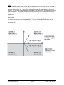
The meter is housed in a DIN mount plastic enclosure intended for mounting on a DIN rail inside of an
electrical panel or enclosure, close to the electrical equipment being monitored.
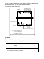
Fig.1 illustrates the WattsOn Isolation Layout
DIGITAL COMMUNICATION (RS-485)
and
ANALOG OUTPUT SIGNALS (0-10Vdc)
and
RELAY PULSES (LOW VOLTAGE)
24VAC or VDC
POWER
SUPPLY
2500Vrms ISOLATION BARRIER
2.5KV RATED RESISTORS
FORM >1Mohm PROTECTIVE
IMPEDANCE BARRIER
NO LINE VOLTAGE OUTSIDE
OF THIS AREA
347Vac L-N (600Vac L-L)
INPUTS
Current Inputs (depending on model number):
mV: 0-1Vac MAX
mA: 0-50mA MAX
5A: 0-10A MAX
(Va, Vb, Vc, N)
** (see note)
Current inputs are always isolated via CTs -- either
internal ("5A" model) or external ("mV" or "mA") model
NOTE (**): THE INPUT LINE VOLTAGE IS USED FOR
MEASUREMENT PURPOSES ONLY
(IE: IT IS NOT USED FOR ANY OTHER
PURPOSE ON THE BOARD)
PROTECTIVE IMPEDANCE LIMITS THE MAXIMUM SHORT
CIRCUIT CURRENT TO 0.6mA (60uA) MAX.
Fig 1. WattsOn Isolation Diagram
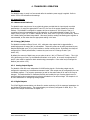
1.3 Features
The WattsOn transducer accepts line voltages up to 600 V directly, without the need for Potential
Transformers (PTs). The line input circuitry is galvanically isolated from the outputs.
The following table summarizes the output features offered by various WattsOn models:
WattsOn-1100
WattsOn-1200
Wh Pulses
User Selectable Qh Pulses/Power Direction Relay
RS-485 Modbus
User Programmable Two 0-10 VDC Analog Outputs
Table 1
ELKOR TECHNOLOGIES INC.
- Page 5 -
WattsOn - USER MANUAL
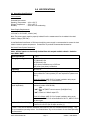
2.0 SPECIFICATIONS
2.1 Operating Specifications
Environmental:
Protected Environment
Operating Temperature : -40 to +60 °C
Storage Temperature : -50 to +85 °C
Humidity
: 10 to 90% non-condensing
Power Supply Requirements:
19-24 VAC or 20-30 VDC, 100mA (max)
Note: The power supply must be properly isolated from the measurement line to maintain the rated
isolation voltage (2500 VAC).
A small dedicated transformer or DIN mount switching power supply is recommended to ensure the best
isolation between system components. Contact Elkor to purchase recommended accessories.
Monitored Power System Parameters:
Note: All line inputs are electrically isolated from the outputs and the chassis. Isolation
test 2500 V RMS.
Input Impedance:
≥ 1 MΩ
Wiring System Types:
120/208 delta, wye
277/480 delta, wye
347/600 delta, wye
Single phase installations up to 347Vrms
Split phase (two phase) installations
Frequency:
45 to 65 Hz
Voltage Inputs:
Direct Input Voltage Max. Rated 600 Vrms (line-to-line), 347 Vrms
line-to-neutral for 4 wire systems (PTs are required for systems over
600 V);
Input Wire Gauge: AWG 12-30, of proper insulation rating as per
electrical code. AWG 16-22 recommended.
Current Inputs:
(model dependent)
"-5A": Standard CTs, 0-5 A, 20% continued overload, 10 A absolute
maximum; burden 0.005 Ω MAX,
-OR"-mA": Elkor MCT/MSCT current sensors (Solid/Split Core)
-OR"-mV": 333mV or 1000mV output CTs
Input Wire Gauge: AWG 12-24, of proper insulation rating as per
electrical code. AWG 12-16 recommended for 5A CTs, AWG 16-22 for
all other types.
Absolute Maximum Ratings:
Voltage: 450 V (Line-to-Neutral) = 780V (Line-to-Line) (*)
Current: 10 A via CTs (for 5A input versions) (*)
(*) Note: These are the absolute maximum values that the unit can withstand without damage. They
are not intended as operating values. See Product Name Tag on the enclosure for the Rated Operating
Line Parameters.
ELKOR TECHNOLOGIES INC.
- Page 6 -
WattsOn - USER MANUAL
2.2 Output Specifications
Output Indicators:
Green LED (PWR): Indicates auxiliary power to the unit
Red LED (Diag.):
Steady: Power is flowing in "reverse" direction.
Slow Flashing: Sequencing Error (see section 4.5)
Fast Flashing: No voltage detected at input terminals (see section 4.5)
Repeating Double-Flash: Hardware error (contact Elkor for support)
Yellow LED (Wh):
Indicates state of output relay #1.
Yellow LED (Qh):
Indicates state of output relay #2. In -1200 models, although the output relay
is not present, the LED operates as in -1100 models.
Output Signals (depending on model):
Pulse Output #1 - solid state relay; <50V, 150mA maximum load, representing Wh accumulation.
Pulse Output #2 (WattsOn-1100) - solid state relay; <50V, 150mA maximum load, representing Qh
accumulation or direction of power flow, may also be used to provide data to the
WattsOn-DISP module.
Pulse outputs are Form A (NO) relay contacts, configured for 100ms pulse duration by default (may be
changed for “change of state” operation — see section 4.5)
Analog Outputs (WattsOn-1200) - Two 0-10VDC outputs representing any instantaneous
measured parameter. Outputs are field configurable via Modbus.
Digital Communication: one RS-485 port, 9600 baud, 8,N,1; Modbus RTU protocol, (see section 4.3 for details);
Information Update Frequency: All outputs and data are updated every 500 ms.
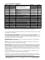
2.3 Accuracy Specification
ANSI C12.20 Class 0.2 Accuracy Certified by NRTL.
All accuracies at 25°C, within 10 to 110% of nominal inputs, PF ≥ 0.5, 5 A Input
Note: Metering grade CTs and PTs are recommended for high accuracy applications.
Parameter
Accuracy (of reading)
Basic Resolution *
Voltage (V)
0.5%
0.1V
Current (A)
0.2%
0.001A (1mA)
Power (W)
0.2%
0.1W (per phase, 1W per total)
Power (VA)
0.5%
0.1VA (per phase, 1VA per total)
Power (VAR)
0.5%
0.1VAR (per phase, 1VAR per total)
Power Factor
0.5%
0.0001
Frequency
0.5%
0.1Hz
Energy
0.2%
1Wh
* Basic resolution must be multiplied by CT and PT ratio for effective resolution per installation.
Analog Output Accuracy: ±0.5% of reading (10 to 100% of output voltage)
ELKOR TECHNOLOGIES INC.
- Page 7 -
WattsOn - USER MANUAL
3.0 INSTALLATION
3.1 Grounding Considerations
Output signal ground is usually provided by the controller (RTU, DDC, PLC etc). The output common
(GND) IS ISOLATED (2500VAC) from the input common (N terminal), however the "-" terminal of the
input power supply and the output common (GND) are tied together internally.
3.2 Power Supply Wiring
The power supply to the WattsOn meter may be either 19-24 VAC or 20-30 VDC, with at least 100mA of
supply current available.
For DC power supplies, the polarity must be observed. For AC power supplies, it must be noted that the
output common (GND) and “-” power supply terminal are tied together. Care must be taken if multiple
devices are powered using one AC supply to prevent shorting the supply.
3.3 Line Circuits Wiring
The WattsOn meter is a true 'three element' meter that can be used in any electrical system. For four
wire systems ('wye', with distributed neutral) the meter requires current and voltage information from
each phase which means that three current transformers (CTs) and three line voltages plus the neutral
must be wired to the unit.
WattsOn may be used in three wire systems ('delta', without a distributed neutral) as a 'three element'
meter (three CTs required). The 5A meter version may be wired as a 'two element' meter utilizing only
two CTs (and two PTs). When no neutral is present, the neutral connection should be omitted.
The wiring diagrams for various power system configurations are shown in Appendix 1.
Standard wiring principles for electricity meters apply to the WattsOn meter, as for any other '3 element'
electricity meter. The polarity of interfacing transformers should be observed. The left terminal of each
current input connector is always associated with the 'X1' wire of the responding CT. Please refer to
Appendix 3 for details on CT wiring.
All mV and Elkor mA CTs must be wired independently to the corresponding current inputs (two wires
from each CT without and shunts or jumpers). mA and mV CTs must NOT be grounded, or
interconnected with each other (or other components) in any way.
The use of a metering test switch containing fuses for voltage lines and shorting terminals for 5A CTs is
recommended. A pre-assembled Elkor i-BlockTM may be used as a convenient and economical solution.
A CT shorting mechanism is not required for mV and Elkor mA style CTs, since these are voltage
clammped, however appropriate protection (fuse or breaker) for input line voltages is requried.
3.4 Fusing of Voltage Sensing Inputs
The input voltage lines should be protected as per electrical code requirements. This is also good
practice to facilitate a easy disconnect means for servicing the meter. In some cases, the voltage may
be tapped off of existing fuses or breakers. If this is not possible, Elkor recommends a 1A or lower fuse
(fast acting) for protection of the installation wiring. The WattsOn voltage inputs are high impedance
(> 1.5MΩ) and draw negligible current (less than 0.3mA max).
ELKOR TECHNOLOGIES INC.
- Page 8 -
WattsOn - USER MANUAL
3.5 Enclosure Mounting
The WattsOn is housed in a plastic enclosure intended for DIN mount installation. All of the input
(bottom) and output (top) signals are available on the exterior of the enclosure. The unit does not
contain any user serviceable parts and thus should not be accessed by the user.
3.6 Indicators and Jumpers
All indication LEDs are located on top of the PCB. They may be helpful for wiring/operation diagnostics.
•
PWR - Green ‘power ON’ LED indicates the presence of power supply to the transducer.
•
DIAG - Red Wiring Diagnostic LED, default configuration as follows:
•
Steady On
: Measured Total Power (sum of all three phases) is negative
Sporadic Flash: Measured Total Power oscillating around +/- 0W
Fast Flashing : Absense (<25VAC) of voltage on input terminals.
Double-Flash : Bootloader error — ensure DIP switch is not set to “zero” (all down),
otherwise contact vendor for more details.
Wh - Yellow Wh LED indicates the energy pulse relay operation (relay #1).
•
Qh - Yellow Wh LED indicates the state of relay #2 in WattsOn-1100 models. In WattsOn-1200,
the LED is for indication only (ie: the relay output is not available).
If WattsOn-DISP is configured (4.5), relay #2 acts as that data source for the DISP module. As
such, the Qh LED will be on / flickering very quickly. This is normal, and should be used as a
diagnostic to ensure that the data output is enabled.
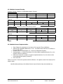
•
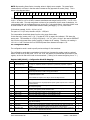
Address DIP switch allows device address selection (1 to 63) to be used in Modbus
communication. (1 is the MSB, 6 is the LSB)
Bit
1
"32"
1
5
30
DOWN
DOWN
DOWN
2
"16"
3
4
"8"
"4"
Examples:
DOWN
DOWN
DOWN
DOWN
DOWN
UP
UP
UP
UP
5
"2"
6
"1"
DOWN
DOWN
UP
UP
UP
DOWN
Table 2
3.7 Accumulated Energy Reset Procedure
Jumper J1 (kWh RESET — located beside power terminal) is used to RESET the device accumulators.
WARNING : The reset action will erase all accumulated energies, and is not reversible !!!
The reset procedure for the meter is as follows:
1.
2.
3.
4.
Apply a shunt to short J1.
Turn power to the meter off, and wait 5 seconds.
Apply power to the meter. At this point all accumulated energies will be set to 0.
Wait 5 seconds, and remove the jumper from J1.
Make sure that the shunt is removed from the J1 position, otherwise
all energy data will be reset upon cycling power to the device.
Energy may be reset via software (see section 4.4.4)
ELKOR TECHNOLOGIES INC.
- Page 9 -
WattsOn - USER MANUAL
4. TRANSDUCER OPERATION
4.1 General
The WattsOn meter is ready in a few seconds after the excitation power supply is applied. Refer to
section 3.5 for LED indication and meanings.
4.2 Output Signals
4.2.1 Measurement Rationale
The WattsOn meter may be used in any electrical system provided that the input signals are within
specifications. By using the appropriate PTs and CTs, the size of the system measured is virtually
limitless. The WattsOn is configured to measure all current inputs as a "5A" full scale. That is; it
normalizes all current measurements as 0-5A depending on the actual calibrated full scale. For this
reason, every CT type is a "CT Ratio" multiplier of xxx:5, even if the CT type is not a 5A variety. Section
4.4.3 details scaling and data interpretation. Whenever possible, reading that floating point registers is
recommended, as the meter does the appropriate scaling in this case.
4.2.2 Energy (Wh) Pulses
The WattsOn transducer offers a Form A ,N.O., solid-state relay output that is triggered after a
predefined amount of energy (Wh) is accumulated. These slow pulses can be easily monitored by any
standard EMS digital input, or by a pulse totalizer or similar counting device. By default, the relays are
configured for a 100ms pulse duration, however they can be set to a “change of state” (see
section 4.5).
By default, the amount of Watt-hours per one pulse is set to 1 Wh (x CT Ratio x PT Ratio) . This 1 Wh
is the total energy as “seen” by the WattsOn transducer on its inputs. As a result, the appropriate CT
and PT ratios must be applied to obtain actual energy consumption. Pulse value may be changed via
Modbus (see section 4.4.4).
4.2.3
Analog Output Signals
The WattsOn-1200 offers two independent 0-10VDC analog signals. Each analog output may be
configured to represent any instantaneous measured value. Each output may be configured by the user
via Modbus registers. The property represented, as well as the scaled value at 0V and at 10V may be
changed. This method allows for maximum flexibility and enables the use of analog signals even for
positive/negative value measurements by allowing introduction of an offset voltage. See chapter 4.4.4
for more information on configuring analog outputs.
4.2.4 Digital Outputs
The RS-485 digital communication port allows for remote monitoring of all the measured parameters via
any Modbus RTU Master device. The communication port is factory configured for 9600, N,8,1. The
details of this output are described in chapter 4.3.
ELKOR TECHNOLOGIES INC.
- Page 10 -
WattsOn - USER MANUAL
4.3 Digital Communications
All WattsOn transducer versions are equipped with digital communications and feature a, RS-485 digital
output port compatible with the Modbus RTU specification. The WattsOn functions as a Modbus Slave
device, and may be addressed between 1 & 63.
4.3.1 Modbus Protocol Specifications
Communications Protocol: WattsOn utilizes a subset of Modicon’s “Modbus RTU” (slave) standard
protocol. There must be a repeater installed if more than 30 units are on the communications chain.
Transmission Mode: Modbus RTU, RS-485 Half-Duplex, 9600 bps, N,8,1. (default)
The baud rate may be selected as 9600 or 57600 by using the extended configuration word (0x9E,
described on page 20 of this manual).
To change the baud rate, valid communication must be established using the baud rate of the device as
configured. If the baud rate is not known, both may be tried in an attempt to establish communication.
Elkor recommends *not* changing the baud rate unless absolutely required. For the majority of
applications, 9600 provides sufficient bandwidth to allow for polling of all parameters more than once
per second.
Communications Principles: The WattsOn transducer stores all of its available information in register
blocks. Modbus function "3" (Read Holding Registers) registers are used to access the data. Some
systems denote these registers as "4XXXX" where "XXXX" is the register offset + 1. For example,
register "function 3, offset 5" would have an address of 40006.
WattsOn implements function 6 and function 16 for single register writes. Note that function 16
(multiple register writes) is implemented in versions > 2.3, however, only single register writes are
supported.
The WattsOn memory map is divided into multiple blocks (addresses provided as offsets):
0x00-0x5A : User data registers (Read Only)
0x80-0x8E : User config registers (Read/Write)
>0x8E : Factory calibration registers
Note: the notation used in this manual is decimal, except when prefaced by "0x" designating
hexadecimal. ie: 45 = "forty-five" decimal; 0x45 = "forty-five" hex or "sixty-nine" decimal.
ELKOR TECHNOLOGIES INC.
- Page 11 -
WattsOn - USER MANUAL
4.3.2 Modbus Command Framing
Command Framing: (Function 3; Read Multiple Words) (8 bytes)
Address Field
Function Code
Starting Register
Number of Registers
1~63
3
0~M
1~N
(1 byte)
(1 byte)
(2 byte)
(2 byte)
CRC
(2 byte)
Response
Address Field
Function Code
Byte Count
1~63
3 or 4
0~N
(1 byte)
(1 byte)
(1 byte)
Data Field... (register M)
Hi Byte
Lo Byte
...Data Field (register M+N)
Hi Byte
CRC
Lo Byte
(2 bytes per register)
(2 bytes)
Command Framing: (Function 6; Write Single Word) (8 bytes)
Address Field
Function Code
Starting Register
Data Field
1~63
6
0~N
(1 byte)
(1 byte)
(2 byte)
(2 byte)
(2 byte)
Address Field
Function Code
Starting Register
Data Field
CRC
1~63
6
0~N
(1 byte)
(1 byte)
(2 byte)
Hi Byte
CRC
Lo Byte
Response
Hi Byte
Lo Byte
(2 byte)
(2 byte)
Table 3
4.3.3 Modbus Protocol Implementation:
•
•
•
•
•
•
Start of frame: No transmission for at least a 3.5 bit period (3.5ms at 9600bps)
Address Field: Applicable addresses are 1~63. The address must match the one defined on
the units DIP switch.
Function Code: 3 = Data Registers; 6 = Write to Configuration Registers.
Starting Register = Contains the number of the first register requested (functions 3), or the
register to write to (function 6).
Data Field: Contains the number of registers requested (functions 3) or the value to write
into the appropriate register (function 6).
CRC: 16 bit CRC
Tables 4.4.1 and 4.4.2 show the registers and their definitions. All registers consist of two bytes (16-bit
integer) values.
Specific details pertaining to the Modbus Protocol may be found at http://www.modbus.org
ELKOR TECHNOLOGIES INC.
- Page 12 -
WattsOn - USER MANUAL
4.4 Modbus Register Function Blocks
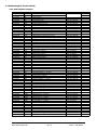
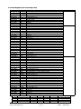
4.4.1 Data Registers (integer)
Register
0x00 (40001)
0x01 (40002)
0x02 (40003)
0x03 (40004)
0x04 (40005)
0x05 (40006)
0x06 (40007)
0x07 (40008)
0x08 (40009)
0x09 (40010)
0x0A (40011)
0x0B (40012)
0x0C (40013)
0x0D (40014)
0x0E (40015)
0x0F (40016)
0x10 (40017)
0x11 (40018)
0x12 (40019)
0x13 (40020)
0x14 (40021)
0x15 (40022)
0x16 (40023)
0x17 (40024)
0x18 (40025)
0x19 (40026)
0x1A (40027)
0x1B (40028)
0x1C (40029)
0x1D (40030)
0x1E (40031)
0x1F (40032)
0x20 (40033)
0x22 (40035)
0x24 (40037)
0x26 (40039)
0x28 (40041)
0x2A (40043)
0x2C (40045)
0x2E (40047)
0x30 (40049)
0x32 (40051)
0x34 (40053)
0x36 (40055)
0x38 (40057)
0x3A (40059)
0x3C (40061)
0x3E (40063)
0x40 (40065)
0x42 (40067)
0x44 (40069)
0x46 (40071)
0x48 (40073)
0x4A (40075)
0x4C (40077)
0x4E (40079)
0x50 (40081)
0x52 (40083)
0x54 (40085)
0x56 (40087)
0x58 (40089)
Units
Wh
W
VAR
VA
Volts
Volts
Amps
Hz
Volts
Volts
Volts
Volts
Volts
Volts
Amps
Amps
Amps
W
W
W
VAR
VAR
VAR
VA
VA
VA
fixed
Wh
Wh
Wh
Wh
Wh
Wh
Wh
Wh
Wh
Wh
Wh
Wh
VARh
VARh
VARh
VARh
VARh
VARh
VARh
VARh
VARh
VARh
VARh
VARh
VAh
VAh
VAh
VAh
WD
ELKOR TECHNOLOGIES INC.
Description
Total Energy Consumption (hi 16)
Total Energy Consumption (lo 16)
Total Real Power
Total Reactive Power
Total Apparent Power
Average Voltage (Line-Neutral)
Average Voltage (Line-Line)
Average Current
Total (System) Power Factor
Frequency
Voltage, phase A-N (line-neutral)
Voltage, phase B-N (line-neutral)
Voltage, phase C-N (line-neutral)
Voltage, phase A-B (line-line) (see 4.4.1)
Voltage, phase B-C (line-line) (see 4.4.1)
Voltage, phase A-C (line-line) (see 4.4.1)
Current, phase A
Current, phase B
Current, phase C
Real Power, phase A
Real Power, phase B
Real Power, phase C
Reactive Power, phase A
Reactive Power, phase B
Reactive Power, phase C
Apparent Power, phase A
Apparent Power, phase B
Apparent Power phase C
Power Factor, phase A
Power Factor, phase B
Power Factor, phase C
Software Version
Import Energy (+), phase A
Import Energy (+), phase B
Import Energy (+), phase C
Total Import Energy (+), (A+B+C)
Export Energy (-), phase A
Export Energy (-), phase B
Export Energy (-), phase C
Total Export Energy (-), (A+B+C)
Net Total Energy (+/-), phase A
Net Total Energy (+/-), phase B
Net Total Energy (+/-), phase C
Net Total Energy (+/-) (A+B+C) (same as 0x00)
Inductive Energy (+), phase A
Inductive Energy (+), phase B
Inductive Energy (+), phase C
Total Inductive Energy (+), (A+B+C)
Capacitive Energy (-), phase A
Capacitive Energy (-), phase B
Capacitive Energy (-), phase C
Total Capacitive Energy (-), (A+B+C)
Net Total VARh (+/-), phase A
Net Total VARh (+/-), phase B
Net Total VARh (+/-), phase C
Net Total VARh (+/-), (A+B+C)
Apparent Energy, phase A
Apparent Energy, phase B
Apparent Energy, phase C
Total Apparent Energy (A+B+C)
Sliding Window Real Power Demand (Total of phases)
- Page 13 -
Data Type
32-bit int (signed)
16-bit
16-bit
16-bit
16-bit
16-bit
16-bit
16-bit
16-bit
16-bit
16-bit
16-bit
16-bit
16-bit
16-bit
16-bit
16-bit
16-bit
16-bit
16-bit
16-bit
16-bit
16-bit
16-bit
16-bit
16-bit
16-bit
16-bit
16-bit
16-bit
16-bit
32-bit
32-bit
32-bit
32-bit
32-bit
32-bit
32-bit
32-bit
32-bit
32-bit
32-bit
32-bit
32-bit
32-bit
32-bit
32-bit
32-bit
32-bit
32-bit
32-bit
32-bit
32-bit
32-bit
32-bit
32-bit
32-bit
32-bit
32-bit
16-bit
int
int
int
int
int
int
int
int
int
int
int
int
int
int
int
int
int
int
int
int
int
int
int
int
int
int
int
int
int
int
int
int
int
int
int
int
int
int
int
int
int
int
int
int
int
int
int
int
int
int
int
int
int
int
int
int
int
int
int
(signed)
(signed)
(unsigned)
(unsigned)
(unsigned)
(unsigned)
(signed)
(unsigned)
(unsigned)
(unsigned)
(unsigned)
(unsigned)
(unsigned)
(unsigned)
(unsigned)
(unsigned)
(unsigned)
(signed)
(signed)
(signed)
(signed)
(signed)
(signed)
(unsigned)
(unsigned)
(unsigned)
(signed)
(signed)
(signed)
(unsigned)
(unsigned)
(unsigned)
(unsigned)
(unsigned)
(unsigned)
(unsigned)
(unsigned)
(unsigned)
(signed)
(signed)
(signed)
(signed)
(unsigned)
(unsigned)
(unsigned)
(unsigned)
(unsigned)
(unsigned)
(unsigned)
(unsigned)
(signed)
(signed)
(signed)
(signed)
(unsigned)
(unsigned)
(unsigned)
(unsigned)
(signed)
Scale
1
1
1
1
1
10
10
1000
10000
10
10
10
10
10
10
10
1000
1000
1000
10
10
10
10
10
10
10
10
10
10000
10000
10000
10
1
1
1
1
1
1
1
1
1
1
1
1
1
1
1
1
1
1
1
1
1
1
1
1
1
1
1
1
1
WattsOn - USER MANUAL
4.4.2 Data Registers (32-bit Floating Point)
Address
0x300 (40769)
0x302 (40771)
0x304 (40773)
0x306 (40775)
0x308 (40777)
0x30A (40779)
0x30C (40781)
0x30E (40783)
0x310 (40785)
0x312 (40787)
0x314 (40789)
0x316 (40791)
0x318 (40793)
0x31A (40795)
0x31C (40797)
0x31E (40799)
0x320 (40801)
0x322 (40803)
0x324 (40805)
0x326 (40807)
0x328 (40809)
0x32A (40811)
0x32C (40813)
0x32E (40815)
0x330 (40817)
0x332 (40819)
0x334 (40821)
0x336 (40823)
0x338 (40825)
0x33A (40827)
0x33C (40829)
0x33E (40831)
0x340 (40833)
0x342 (40835)
0x344 (40837)
0x346 (40839)
0x348 (40841)
0x34A (40843)
0x34C (40845)
0x34E (40847)
0x350 (40849)
0x352 (40851)
0x354 (40853)
0x356 (40855)
0x358 (40857)
0x35A (40859)
0x35C (40861)
0x35E (40863)
0x360 (40865)
0x362 (40867)
0x364 (40869)
0x366 (40871)
0x368 (40873)
0x36A (40875)
0x36C (40877)
0x36E (40879)
0x370 (40881)
0x372 (40883)
0x374 (40885)
0x376 (40887)
Group
1
2
3
Total
Units
kWh
kW
kVAR
kVA
V
V
A
Hz
kW
V
V
V
V
V
V
A
A
A
kW
kW
kW
kVAR
kVAR
kVAR
kVA
kVA
kVA
Fixed
KWh
KWh
KWh
KWh
KWh
KWh
KWh
KWh
KWh
KWh
KWh
KWh
kVARh
KVARh
KVARh
KVARh
KVARh
KVARh
KVARh
KVARh
KVARh
KVARh
KVARh
KVARh
KVAh
KVAh
KVAh
KVAh
Description
Total Energy Consumption
Total Real Power
Total Reactive Power
Total Apparent Power
Average Voltage (L-N)
Average Voltage (L-L)
Average Current
Total (System) Power Factor
Frequency
Sliding Window Real Power Demand (Total of phases)
Voltage A-N
Voltage B-N
Voltage C-N
Voltage A-B
Voltage B-C
Voltage A-C
Current A
Current B
Current C
Real Power A
Real Power B
Real Power C
Reactive Power A
Reactive Power B
Reactive Power C
Apparent Power A
Apparent Power B
Apparent Power C
Power Factor A
Power Factor B
Power Factor C
Software Version
Import Energy (+) A
Import Energy (+) B
Import Energy (+) C
Total Import Energy (+) A+B+C
Export Energy (-) A
Export Energy (-) B
Export Energy (-) C
Total Export Energy (-) A+B+C
Net Total Energy (+/-) A
Net Total Energy (+/-) B
Net Total Energy (+/-) C
Net Total Energy (+/-) A+B+C (Same As 0x300)
Inductive Energy (+) A
Inductive Energy (+) B
Inductive Energy (+) C
Total Inductive Energy (+) A+B+C
Capacitive Energy (-) A
Capacitive Energy (-) B
Capacitive Energy (-) C
Total Capacitive Energy (-) A+B+C
Net Total VARh (+/-) A
Net Total VARh (+/-) B
Net Total VARh (+/-) C
Net Total VARh (+/-) A+B+C
Total VAh A
Total VAh B
Total VAh C
Total VAh (A+B+C)
Description
System Parameters
Phase Parameters
Phase Energy Parameters
ELKOR TECHNOLOGIES INC.
Basic
X
Advanced
X
X
10
32
- Page 14 -
Detailed
X
X
X
60
# Points
10
22
28
60
Group
1
2
3
# Registers (16-bit)
20
44
56
120
WattsOn - USER MANUAL
4.4.3 User Data Register Details
Data Representation
16-bit registers are transferred in the manner defined by the Modbus Protocol. Since there is no 32-bit format
definition in the Modbus specification, 32-bit registers are composed of two 16-bit registers. The method of data
storage is for the lower offset register to represent the upper 16-bit word of the 32-bit integer.
For example, if reading the Total Import Energy register (offset 0x26): If 0x26 = 0xABCD and 0x27=0x1234, then
the resulting 32-bit value is 0xABCD1234.
Floating Point Values (WattsOn versions >= 2.2):
Floating point values are 32-bit and transferred in the same manner as 32-bit integers (MSW followed by LSW).
For example, to read the total energy register (0x00), registers 0x00 and 0x01 must be read and concatenated. If
0x00=0x4145 and 0x01=0x70A4, the resulting floating point value is 0x414570A4 which translates to 12.34.
Floating point registers INCLUDE the CT and PT multipliers, (as defined by the registers 0x80—0x83) and are
represented in the corresponding engineering units (note "kilo" scaling for power and energy parameters).
For the floating point values to show the correctly scaled values, the CT and PT ratios must be programmed via
Modbus.
The word order (MSW/LSW) may be reversed if required (see section 4.5)
Voltages
WattsOn measures all voltages with reference to the "neutral" terminal. Line-to-line voltages are calculated based
on the assumption that the three phase system consists of phases 120° apart from each other. These values are
calculated regardless of the actual input connections, and may be meaningless for single, split or multi phase
systems. For split phase systems, it is correct to sum Va & Vb to obtain the Vab voltage.
Data Scaling
Integer registers must be calculated using appropriate scaling. Many of the registers are represented in
engineering units as factors of 10, and require only the insertion of a decimal point. This includes voltage,
frequency and power factor. To convert the read value to engineering units simply divide by the scale factor.
For example, to properly scale frequency, read register 0x09 and divide by the Scale Factor "10". If the register
reads "602", the actual frequency is "60.2 Hz".
It is EXTREMELY important to understand how current is scaled within the unit. Due to the flexibility of the device
to incorporate a wide variety of CTs, all current inputs are scaled to "5A" full scale. This means that if a typical 5A
CT is used, the value of the register will be the actual current that the transducer sees x 1000. (ie: 2.5A = "2500").
However, if a mA or mV type CTs are used, the full scale output value (either 333/1000mV in the case of mV
output CTs, or full scale current as defined by the configuration in the case of mA CTs) is scaled to represent the
number 5000.
This methodology allows for the use of the same scaling formula to perform calculations regardless of the actual
type of CT used (5A/mV/mA).
The following table lists some examples:
WattsOn Model
WattsOn-XXXX-5A
WattsOn-XXXX-mV-333
WattsOn-XXXX-MSCT2-600
ELKOR TECHNOLOGIES INC.
CT Type Used (example)
"industry standard" (800:5)
mV Output (200A in = 333mV out)
mA Output, 600A input (Elkor MSCT2)
- Page 15 -
Full Scale
800A
200A
600A
"CT Ratio"
800:5
200:5
600:5
Multiplier
160
40
120
WattsOn - USER MANUAL
Power
Although individual (phase) power (W, VA, VAR) is represented with a resolution of 0.1W, the TOTAL W,
VA, VAR is represented with a resolution of 1W. (See register scaling in table 4.4.1). This limitation is
due to the 16-bit register size. Proper CT/PT ratio multipliers must be applied just as for the current
registers. The sign of the power calculation is defined as in the figure below. The sign may be reversed
in the configuration. Alternatively, the sign of the power may be ignored, in cases where it is known
that power will always be either imported or exported. The same principles apply for reactive (VAR)
calculations.
Power Factor
WattsOn uses the convention of Capacitive (Leading, "-"), and Inductive (Lagging, "+") to generate the
sign of the VAR calculation (and thus power factor). The sign of VAR and/or Power factor may be
reversed using the Configuration Word bit settings to obtain readings using the opposite convention
(see section 4.5).
ELKOR TECHNOLOGIES INC.
- Page 16 -
WattsOn - USER MANUAL
4.4.4 User Config Registers (Read/Write)
Number
0x80 (40129)
0x81 (40130)
0x82 (40131)
0x83 (40132)
0x84 (40133)
Name
PT Ratio (Primary)
PT Ratio (Secondary)
CT Ratio (Primary)
CT Ratio (Secondary)
Demand Period
Description
Place holders for PT and CT ratios. The values here
may be used by the Master to calculate actual
engineering units from data received.
0x85 (40134)
Debug
0x86 (40135)
Pulse Value
0x87 (40136)
Reset Register
0x88 (40137)
0x89 (40138)
0x8A (40139)
0x8B (40140)
0x8C (40141)
0x8D (40142)
0x8E (40143)
Output A Source
Output B Source
Output A 0V Value
Output B 0V Value
Output A 10V Value
Output B 10V Value
Configuration Word
Number of minutes to use for sliding window demand
calculations.
Always outputs 12345 (0x3039), for communications
debugging routines
Number of Wh/VARh to accumulate before sending
one pulse.
Energy Reset Register.
See p. 19
Source data register for Analog Output A
Source data register for Analog Output B
Data value at 0V (Output A)
Data value at 0V (Output B)
Data value at 10V (Output A)
Data value at 10V (Output B)
See section 4.5
0x95 (40150)
0x96 (40151)
0x97 (40152)
0x98 (40153)
0x99 (40154)
0x9A (40155)
0x9B (40156)
0x9C (40157)
0x9D (40158)
Serial Number
Scratch Pad [1]
Scratch Pad [2]
Scratch Pad [3]
Scratch Pad [4]
Scratch Pad [5]
Scratch Pad [6]
Scratch Pad [7]
Scratch Pad [8]
Read only, factory programmed
R/W, any arbitrary 16-bit value (user
R/W, any arbitrary 16-bit value (user
R/W, any arbitrary 16-bit value (user
R/W, any arbitrary 16-bit value (user
R/W, any arbitrary 16-bit value (user
R/W, any arbitrary 16-bit value (user
R/W, any arbitrary 16-bit value (user
R/W, any arbitrary 16-bit value (user
data)
data)
data)
data)
data)
data)
data)
data)
Data Type
16-bit int (unsigned)
16-bit int (unsigned)
16-bit int (unsigned)
16-bit int (unsigned)
16-bit int (unsigned)
Default
1
1
**
5
15
16-bit int (unsigned)
12345
16-bit int (unsigned)
1
16-bit int (unsigned)
0
16-bit
16-bit
16-bit
16-bit
16-bit
16-bit
16-bit
int
int
int
int
int
int
int
(unsigned)
(unsigned)
(signed)
(signed)
(signed)
(signed)
(unsigned)
16-bit
16-bit
16-bit
16-bit
16-bit
16-bit
16-bit
16-bit
16-bit
(unsigned)
(user defined)
(user defined)
(user defined)
(user defined)
(user defined)
(user defined)
(user defined)
(user defined)
12345
12345
0
0
12345
12345
5392
N/A
0
0
0
0
0
0
0
0
** The default CT ratio is pre-programmed as the full scale rating of the meter to 5. ie: WattsOn-1100-MCTA-100A would have a CT
ratio pre-programmed as 100:5 (Primary:Secondary). This is used in calculation of the floating point register values.
The user accessible configuration registers (0x80-0x8E) are read/write registers and allow the user to modify
the parameters of the transducer:
CT/PT Radio (Primary and Secondary): The CT/PT ratio registers may be used as placeholders to store
the CT/PT ratio primary and secondary values. This data may be used by the Modbus Master RTU in
calculating true engineering units from integer registers, and is used by the WattsOn in floating point register
value calculation (which include CT/PT ratio multipliers).
Demand Period: Defines the amount of time used to calculate the demand period. The demand period
may be set to between 1 and 45 minutes.
Debug: Contains the (fixed) value 12345 (0x3039) and is read-only. This register is convenient for use
when configuring a system, and verifying proper communications.
Pulse Value Register: Configures the number of Wh / VARh required to generate one pulse on the Wh or
VARh pulse outputs. ie: if this register is set to 10, ten Wh must accumulate before a pulse is triggered. In
this case the pulse value would be 10 Wh / VARh per "click". As with the current and power registers, the
proper PT/CT ratio must be applied to the pulse outputs for proper engineering units. Ie: if the meter is
designed to output 1 pulse per 10Wh, and the CT ratio is 800:5, the value of one click becomes 10 * 800/5
= 1600 Wh (1.6kWh)
Setting the Pulse Value Register to a value of “0” sets the output pulse value to 0.1 Wh/VARh ( x CT/PT
ratios) per pulse. Ie: with a CT ratio of 800:5, the pulse is 16 Wh/pulse.
At settings of “1” or higher (>=1Wh/pulse), the pulse output is a 100ms contact closure. At a setting of
“0” (0.1Wh/pulse) the pulse duration is 50ms with a minimum 50ms interval between pulses. This may have
a bearing on PLC/DDC systems, as some are incapable of detecting short pulse durations.
ELKOR TECHNOLOGIES INC.
- Page 17 -
WattsOn - USER MANUAL
Reset Register: This register is used to reset all of the accumulated energy within the transducer. To
reset the energy, the following sequence must take place:
1. Write the value 0xA5A5 to the reset register
2. Within 1 second, write the value 0x5A5A to the same register
The sequence provides a level of safety to prevent accidental deletion of energy information. This
command will set ALL of the accumulated energy (Wh, VAh, VARh) to zero for every phase.
**Energy Reset capabilities may be permanently disabled at the factory by request
Serial Number: Read-only value representing the serial number of the device (factory programmed).
[WattsOn software versions > 2.0 only]
Scratchpad Registers: Read/Write non-volatile registers available for storage of user data.
[WattsOn software versions > 2.0 only]
Output A/B Source: These registers are used to specify the measured quantity that will be
represented on the respective output. The measured quantity is referenced by INTEGER Modbus
register offset. For example, if "Current, phase A" is to be represented on output A, register 0x88
should be set to the value "0x10".
Note that although ANY Modbus register may be specified into these registers, only instantaneous
parameters (voltage, current, power, frequency, power factor) will be of any significance. (ie: Energy is
an accumulated parameter, and may not be represented well via the analog output).
Output A/B 0V/10V Values: The analog outputs are fully configurable and may be scaled to
represent any span and offset. The data value represented by 0V and by 10V may be entered to define
the range of values for a particular quantity. Both positive and negative values may be entered, thus
allowing representation of positive/negative quantities
(ie: -5000W = 0V, 5000W = 10V, therefore 0W = 5V)
The values entered into these registers should use the same scaling as is used in the respective data
register that is to be represented on the output.
NOTE: When assigning analog outputs, the "integer" registers must be used to define the quantity to
be represented on the analog output. Values should be entered WITHOUT CT and PT ratios, but rather
as "seen" by the meter. Ie: in a 500A system with 500:5A CTs, the value for current must be "5A",
rather than "500A".
For example, if "Frequency" is to be represented on output A, with 0-10V representing 40Hz—60Hz:
1. Register 0x88 = "0x09" (set output A to represent Frequency)
2. Register 0x8A = "400" (set 0V value; 40Hz = 400)
3. Register 0x8C = "600" (set 10V value; 60Hz = 600)
The frequency will now be represented on analog output A.
Example: If a value of 5.5V is measured, the following calculation must be performed:
0V=40Hz; 10V=60Hz; therefore span = 20Hz
5.5V/10V = 0.55 * 20Hz = 11Hz;
Add 0V offset (40Hz) -> 11Hz + 40Hz = 51.0 Hz
ELKOR TECHNOLOGIES INC.
- Page 18 -
WattsOn - USER MANUAL
NOTE: Representing Power factor via analog values is slightly more complex. The power factor
measurement is not linear in that the values increase as they approach the centre (unity). This is
shown in the diagram below:
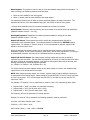
-0.0 -0.1 -0.2 -0.3 -0.4 -0.5 -0.6 -0.7 -0.8 -0.9 1.0 +0.9 +0.8 +0.7 +0.6 +0.5 +0.4 +0.3 +0.2 +0.1 +0.0
0V <———————–—5V—–——————–> 10V
Each analog output may be configured to measure power factor in any range. Typical scaling is
0-10V = -0.0001 to 1.0 to +0.0001, however customized scale ranges such as 0-10V = -0.6 to 1.0 to
+0.6 are also valid. The scale range does not have to be symmetrical, but for ease of calculation, it is
recommended that it be configured that way (so that 5V = unity power factor). Note that 0.0001 must
be used instead of “zero” to differentiate between leading and lagging “+/-0.0” power factor.
In the above example, 0-10V = -0.6 to 1 to 0.6.
The span is 8 "0.1 pf" units, therefore 10V/8 = 1.25V/unit
The interpretation should take place from the unity power factor value.
In this case unity (centre point) = 5V. If a value of 6.75V is output, this indicates 1.75V above the
centre point. This translates to 1.75(V)/1.25(V/unit) = 1.4 "0.1" units = 0.14pf. We need to SUBTRACT
this from the unity power factor (centre position) to obtain the PF reading. Therefore, the reading is
1.0-0.14 = +0.86. We know this is a POSITIVE power factor because the output > 5V.
4.5: Configuration Word
The configuration word is used to specify various settings for the transducer.
The configuration word data is manipulated on the bit level, however the register must be read and
written on the word (16-bits) level. Ie: to "set" a bit, the master RTU should read the contents of the
register, set the bit and write it back to the transducer. ("Setting" a bit means configuring it as a "1".)
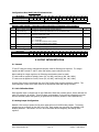
Register 0x8E (40143) – Configuration Word Bit Mapping:
Bit
1
Name
Output #2 Selection
(-1100 model only)
2
Reverse W Sign
3
Reverse VAR Sign
4
Reverse Sequence
5
Disable Sequence
6
Force W Absolute
7
Force VAR Absolute
8
9
10
11
12
13
Force PF Absolute
Pulse on +Wh
Pulse on –Wh
Pulse on +VARh
Pulse on –VARh
No Voltage LED Flash
14
15
32-bit Word Order
V/I Average
16
Split+240V Load
ELKOR TECHNOLOGIES INC.
Description
0=output #2 represents VARh accumulation.
1=output #2 represents direction of power flow (closed relay represents "negative"
power).
Setting this bit reverses the sign of the real power (W) calculation, and thus energy
accumulation.
Setting this bit reverses the sign of the apparent power (VAR) calculation, and thus the
sign of the power factor as well as energy accumulation.
0=expected sequence is ACB
1=expected sequence is ABC
Default
0
This bit effects the sequence error flag as well as the diagnostic LED.
Setting this bit disables the use of the diagnostic LED as sequence error detection.
This bit should be set for single/split phase systems (phase sequence has no relevance
in these systems).
Performs W calculation without sign. WARNING: This setting applies to accumulation of
Wh and pulse signaling.
Performs VAR calculation without sign. WARNING: This settings applies to accumulation
of VARh, pulse signaling and PF calculations also.
When set, Performs PF calculation without sign.
When set, sends pulses (output #1) on accumulation of +Wh
When set, sends pulses (output #1) on accumulation of -Wh
When set, sends pulses (output #2) on accumulation of +VARh
When set, sends pulses (output #2) on accumulation of –VARh
When set, indicates presence of low voltage (<20Vac) on voltage input terminals by
diag LED fast flashing.
When set, 32-bit registers are sent LSB-MSB, when clear (default) order is MSB-LSB
0=Vavg / Iavg are calculated as averages: Vavg=(Va+Vb+Vc)/3; Iavg=(Ia+Ib+Ic)/3
1=Vavg / Iavg are calculated as totals: Vavg=Va+Vb+Vc; Iavg=Ia+Ib+Ic
When set, applies algorithm to channel C to determine line-to-line voltage, power and
energy (see Elkor Application Note AN-306)
- Page 19 -
WattsOn - USER MANUAL
0
0
0
1
0
0
0
1
0
1
0
1
0
0
0
Configuration Word 0x8E (40143) Default Values
Bit Location
Default (bit)
Default (hex)
16
0
15
0
14
0
13
1
12
0
11
1
1
10
0
9
1
8
0
7
0
5
6
0
5
1
4
0
3
0
1
2
0
1
0
0
Register 0x9E (40159) – Extended Configuration Word (firmware v4.5 or greater):
Bit
1
2
4,3
15 to 5
16
Name
Description
Output #2 Display Stream 0=output #2 acts as pulse/relay (normal operation)
(-1100 model only)
1=output #2 sends output data stream for use with WattsOn-DISP
Pulse Output Type
0=100ms pulse output
1=change of state pulse output
Baud rate selection
Two bits required for configuration. Shown in order: Bit 4, Bit 3.
0,0 = 9,600 bps (default)
0,1 = 57,600 bps
1,0 = 19,200 bps (firmware v4.8 or greater)
1,1 = 38,400 bps (firmware v4.8 or greater)
Not used
Default
0
0
0,0
0
Reserved
1
Extended Configuration Word 0x9E (40159) Default Values
Bit Location
Default (bit)
Default (hex)
16
1
15
0
14
0
8
13
0
12
0
11
0
10
0
9
0
8
0
7
0
0
6
0
5
0
4
0
0
3
0
2
0
1
0
0
5. OUTPUT INTERPRETATION
5.1 General
CT and PT ratios are used to calculate and properly scale the floating point registers. The integer
registers do NOT include CT and PT ratios and require proper scaling by the user.
When reading the integer registers, the following considerations must be made:
PT ratios must be applied to Voltage, Power (W, VA, VAR), and Energy (Wh, VAh, VARh).
CT ratios must be applied to Current, Power (W, VA, VAR), and Energy (Wh, VAh, VARh).
As such, Elkor strongly recommends the use of the Floating Point registers whenever possible. This
limits calculation errors as the meter does all the appropriate math and scaling internally.
5.2 Unit Calibration Sheet
Each WattsOn meter is shipped with its Unit Calibration Sheet that provides generic, factory defined, full
scale (FS) values for all outputs. These FS values are dependent on the nominal voltage/current input
and the electrical system configuration (programmed at the factory based on order specifications).
5.3 Analog Output Configuration
WattsOn-1200 versions replace the Qh pulse output with two 0-10VDC analog outputs. The analog
outputs may be configured by the user in the field. Each register may represent any available 16-bit
Modbus parameter. See section 4.4.4 for more information about configuring and scaling these
registers.
ELKOR TECHNOLOGIES INC.
- Page 20 -
WattsOn - USER MANUAL
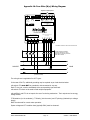
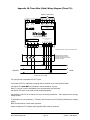
Appendix 1A: Four-Wire (Wye) Wiring Diagram
Signals to EMS System
32 16 8 4 2 1
Power
Diag
Wh
Qh/Dir
+
Power
24V (AC/DC)
MODBUS ADDRESS
Wh
Pulses
A
B G
Output 2
+
G
RS-485
RS-485: Modbus RTU (9600, N, 8, 1)
Output 2: -1100 = Relay output across A
-1200 = 0-10 VDC
Analog 1: A + / GAnalog 2: B + / G -
www.elkor.net
Universal Power Transducer
LINE VOLTAGE IS WIRED
TO THIS TERMINAL
DEACTIVATE BEFORE SERVICING
V1
V2
V3
N
ALWAYS USE APPROPRIATE CTs
(see nameplate)
I11 I12 I21 I22 I31
I32
!! DO NOT Ground or interconnect mV/mA CTs
Interfacing Block (Optional)
Including "Dead-Front" Fuse
Block and CT Shorting Termainls
See: Elkor's i-Block
A
H1
B
H1
SOURCE
LOAD
H1
C
N
(4 WIRE SYSTEM)
The wiring shown is applicable for all CT types.
In the case of 5A CTs, additional grounding may be required as per local electrical codes.
mV and mA CTs must NOT be grounded or interconnected in any way.
Each CT wire pair, must be terminated at the corresponding input terminals.
mV and mA CTs must not be used to feed multiple equipment.
mV and Elkor's mA CTs do not require the use of a shorting mechanism. Their outputs are low energy,
voltage limited.
CT Orientation (on the conductor), CT Polarity (into the meter) and CT phasing (relationship to voltage
phase)
MUST be observed for correct meter operation.
System voltage and CT insulation class (typically 600V) must be observed.
ELKOR TECHNOLOGIES INC.
- Page 21 -
WattsOn - USER MANUAL
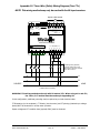
Appendix 1B: Three-Wire (Delta) Wiring Diagram (Three CTs)
Signals to EMS System
32 16 8 4 2 1
Power
Diag
Wh
Qh/Dir
+
Power
24V (AC/DC)
MODBUS ADDRESS
Wh
Pulses
A
B G
Output 2
+
G
RS-485
RS-485: Modbus RTU (9600, N, 8, 1)
Output 2: -1100 = Relay output across A
-1200 = 0-10 VDC
Analog 1: A + / GAnalog 2: B + / G -
www.elkor.net
Universal Power Transducer
LINE VOLTAGE IS WIRED
TO THIS TERMINAL
DEACTIVATE BEFORE SERVICING
V1
V2
V3
N
ALWAYS USE APPROPRIATE CTs
(see nameplate)
I11 I12 I21 I22 I31
I32
!! DO NOT Ground or interconnect mV/mA CTs
Interfacing Block (Optional)
Including "Dead-Front" Fuse
Block and CT Shorting Termainls
See: Elkor's i-Block
A
H1
B
H1
SOURCE
LOAD
H1
C
(3 WIRE "DELTA" SYSTEM)
The wiring shown is applicable for all CT types.
In the case of 5A CTs, additional grounding may be required as per local electrical codes.
mV and mA CTs must NOT be grounded or interconnected in any way.
Each CT wire pair, must be terminated at the corresponding input terminals.
mV and mA CTs must not be used to feed multiple equipment.
mV and Elkor's mA CTs do not require the use of a shorting mechanism. Their outputs are low energy,
voltage limited.
CT Orientation (on the conductor), CT Polarity (into the meter) and CT phasing (relationship to voltage
phase)
MUST be observed for correct meter operation.
System voltage and CT insulation class (typically 600V) must be observed.
ELKOR TECHNOLOGIES INC.
- Page 22 -
WattsOn - USER MANUAL
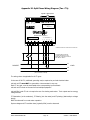
Appendix 1C: Three-Wire (Delta) Wiring Diagram (Two CTs)
NOTE: This wiring method may only be used with the 5A input versions
Signals to EMS System
32
Power
Diag
Wh
Qh/Dir
+
Power
24V (AC/DC)
16
8
4
2
1
MODBUS ADDRESS
Wh
Pulses
RS-485:
A
B G
Output 2
+
G
RS-485
Modbus RTU (9600, N, 8, 1)
Output 2: -1100 = Relay output across A
-1200 = 0-10 VDC
Analog 1: A + / GAnalog 2: B + / G -
www.elkor.net
Universal Power Transducer
LINE VOLTAGE IS WIRED
TO THIS TERMINAL
DEACTIVATE BEFORE SERVICING
V1
V2
V3
N
ALWAYS USE APPROPRIATE CTs
(see nameplate)
I11 I12 I21 I22 I31
I32
Interfacing Block (Optional)
Including "Dead-Front" Fuse
Block and CT Shorting Termainls
See: Elkor's i-Block
A
H1
B
SOURCE
LOAD
C
H1
(3 WIRE "DELTA" SYSTEM)
WARNING: This wiring method works only with 5A meters/CTs. When using mV or mA CTs,
the 3 wire, 3 CT method must be used as per Appending 1B.
In this configuration, additional grounding may be required as per local electrical codes.
CT Orientation (on the conductor), CT Polarity (into the meter) and CT phasing (relationship to voltage
phase) MUST be observed for correct meter operation.
System voltage and CT insulation class (typically 600V) must be observed.
ELKOR TECHNOLOGIES INC.
- Page 23 -
WattsOn - USER MANUAL
Appendix 1D: Split Phase Wiring Diagram (Two CTs)
Signals to EMS System
32 16 8 4 2 1
Power
Diag
Wh
Qh/Dir
+
Power
24V (AC/DC)
MODBUS ADDRESS
Wh
Pulses
A
B G
Output 2
+
G
RS-485
RS-485: Modbus RTU (9600, N, 8, 1)
Output 2: -1100 = Relay output across A
-1200 = 0-10 VDC
Analog 1: A + / GAnalog 2: B + / G -
www.elkor.net
Universal Power Transducer
LINE VOLTAGE IS WIRED
TO THIS TERMINAL
DEACTIVATE BEFORE SERVICING
V1
V2
V3
N
ALWAYS USE APPROPRIATE CTs
(see nameplate)
I11 I12 I21 I22 I31
I32
!! DO NOT Ground or interconnect mV/mA CTs
Interfacing Block (Optional)
Including "Dead-Front" Fuse
Block and CT Shorting Termainls
See: Elkor's I-Block
L1
H1
SOURCE
LOAD
H1
L2
N
("SPLIT PHASE" SYSTEM)
The wiring shown is applicable for all CT types.
In the case of 5A CTs, additional grounding may be required as per local electrical codes.
mV and mA CTs must NOT be grounded or interconnected in any way.
Each CT wire pair, must be terminated at the corresponding input terminals.
mV and mA CTs must not be used to feed multiple equipment.
mV and Elkor's mA CTs do not require the use of a shorting mechanism. Their outputs are low energy,
voltage limited.
CT Orientation (on the conductor), CT Polarity (into the meter) and CT phasing (relationship to voltage
phase)
MUST be observed for correct meter operation.
System voltage and CT insulation class (typically 600V) must be observed.
ELKOR TECHNOLOGIES INC.
- Page 24 -
WattsOn - USER MANUAL
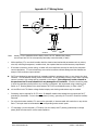
Appendix 2: CT Wiring Notes
Ix1
SOURCE
Note:
Ix2
LOAD
Usually, CTs are marked as shown above, where the ‘H1’ indicates the primary
current input and ‘X1’ the corresponding secondary current terminal (or lead).
•
While specifying CTs, one should consider both the electrical and mechanical parameters such as primary
wire size, mounting arrangement, insulation level, the expected load current and accuracy requirements.
•
If the load is unknown, the bus rating, or better still, the transformer size may be used for the maximum
current calculations. CTs can tolerate large over-correct conditions without damage and the WattsOn can
accept a 20% continuous input overload.
•
5A CTs are designed to operate with their secondary winding in permanent short, or very close to the short
condition. The 5A WattsOn models provide 0.05Ω burden. If the secondary winding is open while a primary
current is present, high voltage will be generated on the output. This voltage may create a hazard to
the personnel and in some situations it may damage the CT insulation. Provisions should be made
to short the secondary winding before any re-wiring is performed. We recommend using a metering Test
Switch or CT Shunting Blocks to be wired between 5A CTs/PTs and WattsOn meter (ie: Elkor i-BlockTM).
•
mV and Elkor’s mA CTs feature voltage limited outputs, and shorting mechanisms may be omitted.
•
Grounding may be required for 5A CTs only. 5A WattsOn models have isolated current inputs and 5A CT
grounding is permissible. For two element systems (3 wires), grounding of CTs and PTs should be carefully
observed.
•
For mV and mA meter models, CTs must not be grounded, or interconnected with each other or any device.
Each CT wire pair must be terminated at the corresponding meter current inputs.
•
CT Orientation (on the conductor), CT Polarity (into the meter) and CT phasing (relationship to voltage
phase) MUST be observed for correct meter operation.
ELKOR TECHNOLOGIES INC.
- Page 25 -
WattsOn - USER MANUAL
Elkor Technologies Inc.
6 Bainard Street
London, Ontario
N6P 1A8
Tel: 519-652-9959
Fax: 519-652-1057
www.elkor.net
© 2014, Elkor Technologies Inc.