1
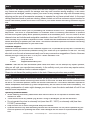
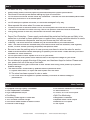
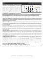
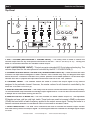
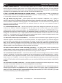
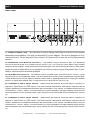
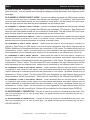
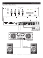
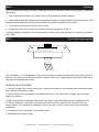
MIC 1
MASTER LEVEL
PHONO 1
LINE 1
10
MIC 1
VOLUME
���
5
5
5
LINE 6
5
+5
0
-5
RIGHT
-10 -15
-15 -10
-5
0
+5
POWER
���
���
5
LEFT
LINE 5
LINE 4
LINE 2
���
0
LINE 3
PHONO 2
5
0
5
5
10 0
BASS
10 0
MID LOW
10 0
MID HIGH
10
TREBLE
���
CUE
CUE
������������
������ �����
CUE
CUE
10
0
10
0
MIC 2
VOLUME
� � �
���
�
������� �����
� � �
���
MASTER
LEVEL
�
10
0
ASSIGN CH
ASSIGN CH
BOOTH
LEVEL
CUE
PGM
CUE
MIXING
10
0
CUE
LEVEL
PHONES
DX4
™
Professional Preamp Mixer
AMERICAN AUDIO
4295 Charter Street
Los Angeles Ca. 90058
www.americandj.com
DX4™
Unpacking
Every DX4™ has been thoroughly tested and has been shipped in perfect operating condition. Carefully check the shipping carton for damage that may have occurred during shipping. If the carton
appears to be damaged, carefully inspect your mixer for any damage that may have occurred during
shipping and be sure all accessories necessary to operate the unit have arrived intact. In the event
damage has been found or parts are missing, please contact our toll free customer support number for
further instructions, please do not return the mixer to your dealer without contacting customer support
first.
DX4™
Introduction
Introduction:
Congratulations and thank you for purchasing the American Audio® DX4™ professional audio preamp/mixer. This mixer is a representation of American Audio’s continuing commitment to produce
the best and highest quality audio products possible at an affordable price. The DX4 mixer is a four
channel mixer and includes and assignable crossfader, a four band EQ, two mic inputs and other features normally only included in expensive mixers. Please read and understand this manual completely
before attempting to operate your new mixer. This booklet contains important information concerning
the proper and safe operation of your new mixer.
Customer Support:
American Audio® provides a toll free customer support line, to provide set up help and to answer any
question should you encounter problems during your initial set up or operation of this unit. You may
also visit us on the web at www.americandj.com for any comments or suggestions. Service Hours are
Monday through Friday 9:00 a.m. to 5:30 p.m. Pacific Standard Time.
Voice:
(800) 322-6337
Fax:
(323) 582-2610
E-mail:
[email protected]
Caution! There are no user serviceable parts inside this mixer. Do not attempt any repairs yourself,
doing so will void your manufactures warranty. In the unlikely event your mixer may require service,
please contact American Audio® customer support.
Please do not discard the packing carton in the trash. Please recycle when ever possible.
DX4™
Set-Up Precautions
Please be sure to make all connections before you plug the mixer in. Be sure the power switch is in
the “OFF” position before connecting other devices to the mixer. All fader and volume controls should
be set to 0 or minimum position, before the device is switched on. If the device has been exposed to
drastic temperature fluctuation (e.g. after transportation), do not switch on the mixer immediately. The
arising condensation of water might damage your device. Leave the device switched off until it has
reached room temperature.
Operating Determinations:
• When installing this mixer, please make sure that the device is not exposed to extreme heat,
moisture or dust!
• There should not be any cables lying around. Doing so endangers you as well as others.
• Do not operate the mixer in extremely hot (more than 30° / 100°F) or extremely cold (less than
5°C/40°F) surroundings.
• Keep the unit out of direct sunlight and away from heaters.
• Operate the mixer only after becoming familiar with its functions. Do not permit operation by persons not qualified for operating the mixer. Most damages are the result of unprofessional operation!
©American
Audio® - www.americandj.com - DX4™ Instruction Manual Page 2
DX4™
•
•
•
•
•
•
•
•
•
•
•
•
•
•
•
•
•
•
•
•
•
•
Safety Precautions
For adult use only - Keep out of the reach of children.
Always use a power cord that meets the manufactures exact power specifications
Disconnect from main power before making any type of connection.
Do not remove the mixer covers under any conditions. There are no user serviceable parts inside.
Never plug this mixer in to a dimmer pack
Always be sure to mount this mixer in an area that will allow proper ventilation.
Do not attempt to operate this mixer, if it becomes damaged in any way.
Never operate this mixer when it’s covers are removed
To reduce the risk of electrical shock or fire, do not expose this mixer rain or moisture
This mixer is intended for indoor use only, use of this product outdoors voids all warranties.
During long periods of non-use, disconnect the mixer’s main power.
Always mount this mixer in safe and stable matter.
Power Cord Protection - Power supply cords should be routed so that they are not likely to be
walked on or pinched by items placed upon or against them, paying particular attention to cords
at plugs, convenience receptacles, and the point where they exit from the mixer.
Cleaning -The mixer should be cleaned only as recommended by the manufacturer.
Heat -The mixer should be situated away from heat sources such as radiators, heat registers,
stoves, or other mixers (including amplifiers) that produce heat.
Be sure to save the packing carton in case you may ever have to return the mixer for service.
Read all documentation before attempting to operate your new mixer. Please save all your documentation for future reference.
Do not spill water or other liquids in to or on to your mixer.
Be sure that the local power outlet matches that of the required voltage for your mixer.
Do not attempt to operate this mixer if the power cord has been frayed or broken. Please route
your power cord out of the way of foot traffic .
Always have the front gain controls set to their lowest level during initial power-up to prevent
speaker damage.
The mixer should be serviced by qualified service personnel when:
A. Objects have fallen, or liquid has been spilled into the mixer.
B. The mixer has been exposed to rain or water.
C. The mixer does not appear to operate normally or exhibits a marked change in
performance.
DX4™
Main Features
• Equipped with high quality Crossfader
• User Replaceable Crossfader
• High Headphones Output
• Cue Mixing
• Extremely clean signal to noise ratio
• Two Turntable Ground Prongs
• Soft-touch rubber knobs for better control
• External Power Supply
©American
• Low Residue Resistance Crossfader
• 4 Band Master EQ
• 2 Phono, & 6 Line Level Inputs
• Split Cue Monitoring
• Assignable Crossfader
• Separate Booth Level Output
• Balanced XLR Outputs
• 2 Mic Inputs
Audio® - www.americandj.com - DX4™ Instruction Manual Page 3
DX4™
QUICK START INSTRUCTIONS
American Audio would like to thank for your
purchase of this great product. For those of
you that are to impatient to read the entire user
manual we have compiled these quick start
instructions. We hope that you will at least read
���
through these instructions to familiarize yourself with the basic understanding of the unit.
The DX4™ is part of American Audio’s continuing evolution in audio technology. This unit has
been built and designed with the typical DJ in mind, by DJ’s. We have attempted to provide you with
the most reliable product on the market by using only components made from quality products.
MIC 1
MASTER LEVEL
PHONO 1
10
MIC 1
VOLUME
���
5
5
CUE
5
LINE 6
5
CUE
+5
0
-5
RIGHT
-10 -15
-15 -10
MIC 2
VOLUME
� � �
���
�
5
5
5
0
10 0
BASS
������� �����
+5
10 0
MID LOW
10 0
MID HIGH
10
TREBLE
������������
������ �����
CUE
CUE
� � �
10
���
MASTER
LEVEL
�
10
0
ASSIGN CH
0
POWER
0
10
0
-5
���
���
5
LEFT
LINE 5
LINE 4
LINE 2
���
0
LINE 3
PHONO 2
LINE 1
ASSIGN CH
BOOTH
LEVEL
CUE
PGM
CUE
MIXING
10
0
CUE
LEVEL
PHONES
MASTER LEVEL (5) - Use this level control to set your volume output. Try never to send an output
of more than +4dB to your system. Signal at levels higher than this will start to distort and may cause
damage to your system and speakers. Remember that a distorted signal from you mixer will only be
multiplied throughout your system.
HEADPHONES (16) - To avoid sever hearing damage, always be sure the headphone level is set
to minimum before plugging them in. Never put the headphone on without making sure the headphone
level is turned down.
MICROPHONE 1 (1) - The main mic connector uses a 1/4” jack unbalanced connector on the rear
of the unit or XLR balanced connection on the face of the unit. Both microphone connection marks
as MIC 1 are controlled by the MIC 1 VOLUME knob. Always leave the mic level to it’s minimum level
when not in use.
BALANCED XLR OUTPUTS (18) - The Master Output includes a pair XLR Balanced JACKS as
well as a pair RCA UNBALANCED JACKS (19). The 3-pin XLR jacks send a high current balanced
output signal. These jacks should be used when you will be driving an amp or other audio equipment
with a balanced input, or whenever you will be running a signal line greater than 15 feet. Always, use
these jacks whenever possible.
FADER ASSIGN SWITCH (11) - This is a five position switch that assigns a channel to the
CROSSFADER (12). When a channel is assigned to the left side of the CROSSFADER (12) that channels output level is routed to and controlled by the CROSSFADER (12). Sliding the CROSSFADER (12)
to left position will send the volume output of the assigned channel to the MASTER VOLUME LEVEL
(5), siding the CROSSFADER (12) to right position will cut that channels volume to MASTER VOLUME
LEVEL (5). The reverse is true for the right channel fader assign switch. When the assign switch is set
to the "OFF" position the crossfader will have no function.
BOOTH LEVEL (BOOTH LEVEL VOLUME CONTROL) (13) - This rotary knob is used to
control the output volume to any source connect to the BOOTH OUTPUT JACKS (25) on the rear of the
unit. Be sure this volume control is always set to zero before turning the unit on and off.
©American
Audio® - www.americandj.com - DX4™ Instruction Manual Page 4
DX4™
Controls and Features
Top Panel
1
2
3
4
5
6
7
8
MIC 1
MASTER LEVEL
PHONO 1
LINE 1
10
5
5
MIC 1
VOLUME
���
5
LINE 6
5
+5
0
-5
RIGHT
-10 -15
-15 -10
-5
0
+5
POWER
���
���
5
LEFT
LINE 5
LINE 4
LINE 2
���
0
LINE 3
PHONO 2
5
5
5
0
10 0
BASS
10 0
MID LOW
10 0
MID HIGH
10
TREBLE
���
CUE
������������
������ �����
CUE
CUE
CUE
10
0
� � �
10
0
MIC 2
VOLUME
���
�
������� �����
� � �
���
MASTER
LEVEL
�
10
0
ASSIGN CH
9
10
11
ASSIGN CH
12
BOOTH
LEVEL
13
CUE
PGM
10
0
CUE
MIXING
CUE
LEVEL
14
15
PHONES
16
1. MIC 1 VOLUME (MICROPHONE 1 VOLUME LEVEL) - This rotary knob is used to control the
volume output level for any microphone connected to the MIC 1 INPUT JACKS (2 or 31) . Turning the
knob in a clockwise direction will increase volume output.
2. MIC 1 (MICROPHONE 1 INPUT) - This jack accepts a standard XLR 3-pin balanced male plug. The
volume output level for this microphone is controlled by the MIC 1 VOLUME KNOB (1).
3. CHANNEL SOURCE SELECTOR SWITCH (TRANSFORMER SWITCH) - These switches are used
to select the input source assigned to each channel. Each channel may only be assigned one input
source at a time. This switch must be in the “phono” position for turntable operation. For all other input
devices such as CD players and tape decks this switch must be in the “line” position.
4. CHANNEL FADER - The channel faders are used to control the output signal of any source
assigned to its particular channel. However, the master volume for all channels is controlled by the
MASTER VOLUME CONTROL (5).
5. MASTER VOLUME CONTROL - This rotary knob is used to control the master output level (volume).
To avoid distorted output maintain an average output signal level of +4 dB. Be sure this volume control
is always set to zero before turning the unit on.
6. MASTER OUTPUT 4-BAND EQ - The DX4 includes a 4-band master output EQ. The adjustable
EQ bands are bass, mid low, mid high, treble. These knobs are used to increase (+20dB) or decrease
(-30dB) the band width of each frequency applied to the output source signal. Turning the knobs in a
counter-clockwise direction to decrease a value or clockwise to increase a value.
7. LEVEL INDICATORS - The dual LED’s indicators are used to indicate the master output volume
level and directly reflect the output signal. To avoid signal distortion maintain an average signal output
of +4dB.
©American
Audio® - www.americandj.com - DX4™ Instruction Manual Page 5
DX4™
Controls and Features Cont.
8. MAIN POWER SWITCH - This is the main power ON/OFF button. A red LED below the power
switch will glow indicating main power is on. Before main power is applied, be sure you have made all
connections to the mixer. Also be sure your amplifier(s) is(are) turned off. Remember to avoid damaging pops to your speakers, the mixer is turned on first and turned off last.
9. MIC 2 VOLUME (MICROPHONE 2 VOLUME LEVEL) - This rotary knob is used to control the
volume output level for any microphone connected to the MIC 2 INPUT JACK (30). Turning the knob
in a clockwise direction will increase volume output.
10. CUE SELECTOR BUTTON - These buttons are used to activate a channels “CUE” mode. A
red LED next to the Cue Selector Button will glow when a channels cue mode is activated. The Cue
function sends a channels incoming signal to the headphones. The cue volume level is adjusted by
the CUE LEVEL KNOB (15). Be sure the CUE MIXING KNOB (14) is in the “CUE” position to hear a
selected channel‘s source.
11. FADER ASSIGN SWITCH - This is a five position switch that assigns a channel to the CROSSFADER (12). When a channel is assigned to the left side of the CROSSFADER (12) that channels
output level is routed to and controlled by the CROSSFADER (12). Sliding the CROSSFADER (12) to
left position will send the volume output of the assigned channel to the MASTER VOLUME LEVEL (5),
siding the CROSSFADER (12) to right position will cut that channels volume to MASTER VOLUME
LEVEL (5). The reverse is true for the right channel fader assign switch. When the assign switch is set
to the "OFF" position the crossfader will have no function.
12. FEATHER FADER PLUS CROSSFADER - This fader is used to blend the output signals of any two
channels together. When the fader is in the full left position, the output signal of any channel assigned
to the left side of the fader will be controlled by the master volume level. The same fundamentals will
apply for any channel assigned to the right side of the fader. Sliding the fader from left position to the
right will vary the output signals of any two channels respectively. When the crossfader is set in the
center position, the output signals of both channels will be even.
13. BOOTH LEVEL (BOOTH LEVEL VOLUME CONTROL) - This rotary knob is used to control the
output volume to any source connect to the BOOTH OUTPUT JACKS (25) on the rear of the unit. Be
sure this volume control is always set to zero before turning the unit on and off.
14. CUE MIXING CONTROLLER - This knob is used to select the monitoring source, either the master
output or a channel. The cue level is prefader and is not affected by a channel’s fader level. To monitor the master output signal turn the knob to the “PGM” position to monitor a channel signal turn the
knob to the “CUE” position. To vary the amount of either signal turn the knob more or less to the center
position. If the knob is set to the center position, you can monitor both the cue and master output levels
equally.
15. CUE LEVEL VOLUME CONTROL - This knob adjusts the headphone volume output level. Turning
the knob in clockwise direction will increase headphone volume output.
16. HEADPHONE JACK - This jack is used to connect your headphones to the mixer allowing you to
monitor the cue source. Use headphones only rated at 8 ohms to 32 ohms. Most DJ headphones are
rated at 16 ohm, these are highly recommended. Always be sure the CUE LEVEL VOLUME (12) is set
to minimum before you put the headphones on.
©American
Audio® - www.americandj.com - DX4™ Instruction Manual Page 6
DX4™
Controls and Features Cont.
Rear Panel
17
AMERICAN AUDIO
PREAMP MIXER
MODEL NO. DX-4
AC 18V ~ 50/60HZ 20W
18
19
20
21
22 23
24 22
CAUTION
RISK OF ELECTRIC SHOCK
DO NOT OPEN
AVIS:RISQUE DE CHOC ELECTRIQUE-NE
PAS OUVRIR.
25
26
27 28
29
30
31
17. POWER CONNECTION - This connector is used to supply main power to the unit via the included
detachable power adaptor. Use only the supplied AC power adaptor. This cord is designed to fit in
one direction only. Do not attempt to force a cord in if it does not fit, be sure the cord is being inserted
properly
18. BALANCED XLR MASTER OUTPUTS - The Master Output includes a pair XLR Balanced
JACKS as well as a pair RCA UNBALANCED JACKS (19). The 3-pin XLR jacks send a high current
balanced output signal. These jacks should be used when you will be driving an amp or other audio
equipment with a balanced input, or whenever you will be running a signal line greater than 15 feet.
Always, use these jacks whenever possible.
19. RCA MASTER OUTPUTS - The Master Output includes a pair XLR BALANCED JACKS (18) as
well as a pair RCA Unbalanced Jacks. The RCA jacks send a low current unbalanced output signal.
These jacks should only be used for shorter cable runs to signal processors or looping to another
mixer. For cable runs greater than 15 feet use the XLR BALANCED JACKS (18).
20. CHANNEL 4: LINE 6 INPUT JACKS - These Jacks are used for line level inputs. Connect CD
players or Tape Decks to LINE inputs. Line level musical instruments with stereo outputs such as
Rhythm Machines or Samplers should also be connected to LINE inputs. Turntables should only be
connected to “Phono” inputs. The red colored RCA jack represents the right channel input and the
white represents the left channel input. Input volume will be controlled by the channel four FADER
(4).
21. CHANNEL 3: LINE 4 INPUT JACKS - These Jacks are used for line level inputs. Connect CD
players or Tape Decks to LINE inputs. Line level musical instruments with stereo outputs such as
Rhythm Machines or Samplers should also be connected to LINE inputs. Turntables should only be
connected to “Phono” inputs. The red colored RCA jack represents the right channel input and the
white represents the left channel input. Input volume will be controlled by the channel three FADER
(4).
©American
Audio® - www.americandj.com - DX4™ Instruction Manual Page 7
DX4™
Controls and Features Cont.
22. GND (GROUND TERMINAL) - Connect each of your turntables ground leads to either of the two
ground terminal. This will reduce the humming and popping noises associated with magnetic phono
cartridges.
23. CHANNEL 2: PHONO 2 INPUT JACKS - Connect turntables equipped with MM pickup cartridge
to PHONO inputs only (All DJ turntable use MM pick-up cartridges). CD players or Tape Decks and
other line level instruments should not be connected to these jacks. The red colored RCA jack represents the right channel input and the white represents the left channel input.
24. CHANNEL 1: PHONO 1 INPUT JACKS - Connect turntables equipped with MM pickup cartridge
to PHONO inputs only (All DJ turntable use MM pick-up cartridges). CD players or Tape Decks and
other line level instruments should not be connected to these jacks. The red colored RCA jack represents the right channel input and the white represents the left channel input.
25. RCA BOOTH OUTPUTS JACKS - These RCA jacks send a low current unbalanced output signal
and are controlled by the BOOTH LEVEL (13) volume control. These jacks should only be used for
shorter cable runs to signal processors or looping to another mixer.
26. CHANNEL 4: LINE 5 INPUT JACKS - These Jacks are used for line level inputs. Connect CD
players or Tape Decks to LINE inputs. Line level musical instruments with stereo outputs such as
Rhythm Machines or Samplers should also be connected to LINE inputs. Turntables should only be
connected to “Phono” inputs. The red colored RCA jack represents the right channel input and the
white represents the left channel input. Volume will be controlled by the channel four FADER (4).
27. CHANNEL 3: LINE 3 INPUT JACKS - These Jacks are used for line level inputs. Connect CD
players or Tape Decks to LINE inputs. Line level musical instruments with stereo outputs such as
Rhythm Machines or Samplers should also be connected to LINE inputs. Turntables should only be
connected to “Phono” inputs. The red colored RCA jack represents the right channel input and the
white represents the left channel input. Volume will be controlled by the channel three FADER (4).
28. CHANNEL 2: LINE 2 RCA INPUT JACKS - These Jacks are used for line level inputs. Connect
CD players or Tape Decks to LINE inputs. Line level musical instruments with stereo outputs such as
Rhythm Machines or Samplers should also be connected to LINE inputs. Turntables should only be
connected to “Phono” inputs. The red colored RCA jack represents the right channel input and the
white represents the left channel input. Volume will be controlled by the channel three FADER (4).
29. CHANNEL 1: LINE 1 RCA INPUT JACKS - These Jacks are used for line level inputs. Connect
CD players or Tape Decks to LINE inputs. Line level musical instruments with stereo outputs such as
Rhythm Machines or Samplers should also be connected to LINE inputs. Turntables should only be
connected to “Phono” inputs. The red colored RCA jack represents the right channel input and the
white represents the left channel input. Volume will be controlled by the channel three FADER (4).
30. MICROPHONE 1 CONNECTOR - This jack is used to a connect a microphone to the mixer. Connect you microphone via 1/4 inch (6.3mm) jack. The signal volume will be controlled by the MIC 1
VOLUME KNOB (1).
31. MICROPHONE 2 CONNECTOR - This jack is used to a connect a microphone to the mixer. Connect you microphone via 1/4 inch (6.3mm) jack. The signal volume will be controlled by the MIC 2
VOLUME KNOB (1).
©American
Audio® - www.americandj.com - DX4™ Instruction Manual Page 8
DX4™
Typical Mixer Set-Up
Typical Mixer Input Set-Up
MIC 1
MASTER LEVEL
PHONO 1
LINE 1
10
MIC 1
VOLUME
���
5
5
5
LINE 6
5
+5
0
-5
RIGHT
-10 -15
-15 -10
-5
0
+5
POWER
���
���
5
LEFT
LINE 5
LINE 4
LINE 2
���
0
LINE 3
PHONO 2
5
0
5
5
10 0
BASS
10 0
10 0
MID LOW
MID HIGH
10
TREBLE
���
CUE
CUE
������������
������ �����
CUE
CUE
10
0
10
0
MIC 2
VOLUME
� � �
���
������� �����
�
� � �
���
MASTER
LEVEL
�
10
0
ASSIGN CH
AMERICAN AUDIO
PREAMP MIXER
MODEL NO. DX-4
AC 18V ~ 50/60HZ 20W
ASSIGN CH
CUE
PGM
10
0
CUE
LEVEL
CUE
MIXING
BOOTH
LEVEL
PHONES
CAUTION
RISK OF ELECTRIC SHOCK
DO NOT OPEN
AVIS:RISQUE DE CHOC ELECTRIQUE-NE
PAS OUVRIR.
OFF
ON
POWER
1 2 3 4 5 6 7 8 9 0
CUE
PARAMETER TIME
PROGRAM
NONSTOP
ELAPSED TOTAL REMAIN
AUTO
CUE BPM
BEAT SYNC.
KEY
LOCK
EJECT
SINGLE
LOOP
RELOOP
BPM
T
M
S
PITCH
F
PARAMETER RATIO
CASSETTE DECK
SCRATCH
FILTER
SKID
PHASE
HOLD
ECHO
TRANS
FLANGER
PAN
FX SELECT
SGL/CTN
TIME
REV.PLAY
TEMPO
LOCK
ON/OFF
4%/8%/16%
BOP
SAMPLE PITCH
FX
MIX
ENTER
� � � � �� � � �
� � � � �� � � �
©American
Audio® - www.americandj.com - DX4™ Instruction Manual Page 9
DX4™
Typical Mixer Set-Up
Typical Mixer Output Set-Up
MIC 1
MASTER LEVEL
PHONO 1
LINE 1
10
MIC 1
VOLUME
���
5
5
5
LINE 6
5
+5
0
-5
RIGHT
-10 -15
-15 -10
-5
0
+5
POWER
���
���
5
LEFT
LINE 5
LINE 4
LINE 2
���
0
LINE 3
PHONO 2
5
5
5
0
10 0
BASS
10 0
MID LOW
10 0
MID HIGH
10
TREBLE
���
CUE
CUE
������������
������ �����
CUE
CUE
10
0
10
0
MIC 2
VOLUME
� � �
���
�
������� �����
� � �
���
MASTER
LEVEL
�
10
0
ASSIGN CH
AMERICAN AUDIO
PREAMP MIXER
MODEL NO. DX-4
AC 18V ~ 50/60HZ 20W
ASSIGN CH
BOOTH
LEVEL
CUE
PGM
CUE
MIXING
10
0
CUE
LEVEL
PHONES
CAUTION
RISK OF ELECTRIC SHOCK
DO NOT OPEN
AVIS:RISQUE DE CHOC ELECTRIQUE-NE
PAS OUVRIR.
Stereo RCA
XLR-XLR Balanced cables
CASSETTE DECK
V4000 Amplifier
Speaker Cables
©American
Audio® - www.americandj.com - DX4™ Instruction Manual Page 10
DX4™
Cleaning
Due to fog residue, smoke, and dust, cleaning the mixer should be carried out periodically to optimize
light output.
1. Use normal glass cleaner and a soft cloth to wipe down the outside casing.
2. Use a cleaner specially designed for electronics to spray in and around the knobs and switch. This
will reduce small particle built up that can effect the proper operation of the mixer.
3. Clean should be carried out every 30-60 days.
4. Always be sure to dry all parts completely before plugging the mixer in.
Cleaning frequency depends on the environment in which the mixer operates (i.e. smoke, fog residue,
dust, dew).
DX4™
Cross Fader Replacement
The crossfader is “Hot Swappable” which means it may be replaced at any time, even when power is
applied. Only replace with American Audio Feather Fader Plus. Replacing with any other model fader
may seriously damage your mixer.
Replacing the Crossfader:
1. Using a number two Phillips screw driver, unscrew the each of the stainless steel retaining screws
that hold the crossfader in place.
2. Gently remove the crossfader from its seated position. You may need to wiggle the crossfader
slightly to unseat it.
3. After removing the crossfader, disconnect the ribbon cable that attaches the crossfader to the
PC board. Grasp the crossfader by its base and pull the ribbon cable by its connector not the
actual cables. The connector is desired to only fit one way, so don’t worry about the connectors
orientation.
4. Connect the new crossfader to the ribbon cable.
5. Reassemble in reverse order.
©American
Audio® - www.americandj.com - DX4™ Instruction Manual Page 11
DX4™
Warranty
The DX4™ carries a two year limited warranty. We recommend you fill out the enclosed warranty card
to validate your purchase. All returned service items whether under warranty or not, must be freight
pre-paid and accompany a R.A.(return authorization) number. If the mixer is under warranty, you must
provide a proof of purchase invoice. You may obtain a R.A. number by contacting our customer support team on out toll free number.
DX4™
Main Features
2-YEAR LIMITED WARRANTY
A. American Audio® hereby warrants, to the original purchaser, American Audio® products to be free
of manufacturing defects in material and workmanship for a period of 2 Year (730 days) from the date
of purchase. This warranty shall be valid only if the product is purchased within the United States of
America, including possessions and territories. It is the owner’s responsibility to establish the date and
place of purchase by acceptable evidence, at the time service is sought.
B. For warranty service, send the product only to the American Audio® factory. All shipping charges
must be pre-paid. If the requested repairs or service (including parts replacement) are within the terms
of this warranty, American Audio® will pay return shipping charges only to a designated point within
the United States. If the entire instrument is sent, it must be shipped in its original package. No accessories should be shipped with the product. If any accessories are shipped with the product, American
Audio® shall have no liability whatsoever for loss of or damage to any such accessories, nor for the
safe return thereof.
C. This warranty is void if the serial number has been altered or removed; if the product is modified in
any manner which American Audio® concludes, after inspection, affects the reliability of the product;
if the product has been repaired or serviced by anyone other than the American Audio® factory unless
prior written authorization was issued to purchaser by American Audio®; if the product is damaged
because not properly maintained as set forth in the instruction manual.
D. This is not a service contract, and this warranty does not include maintenance, cleaning or periodic check-up. During the period specified above, American Audio® will replace defective parts at
its expense, and will absorb all expenses for warranty service and repair labor by reason of defects
in material or workmanship. The sole responsibility of American Audio® under this warranty shall be
limited to the repair of the product, or replacement thereof, including parts, at the sole discretion of
American Audio®. All products covered by this warranty were manufactured after January 1, 1990, and
bear identifying marks to that effect.
E. American Audio® reserves the right to make changes in design and/or improvements upon its products without any obligation to include these changes in any products theretofore manufactured.
F. No warranty, whether expressed or implied, is given or made with respect to any accessory supplied with products described above. Except to the extent prohibited by applicable law, all implied
warranties made by American Audio® in connection with this product, including warranties of merchantability or fitness, are limited in duration to the warranty period set forth above. And no warranties, whether expressed or implied, including warranties of merchantability or fitness, shall apply to
this product after said period has expired. The consumer’s and or Dealer’s sole remedy shall be such
repair or replacement as is expressly provided above; and under no circumstances shall American
Audio® be liable for any loss or damage, direct or consequential, arising out of the use of, or inability
to use, this product.
G. This warranty is the only written warranty applicable to American Audio® Products and supersedes
all prior warranties and written descriptions of warranty terms and conditions heretofore published.
©American
Audio® - www.americandj.com - DX4™ Instruction Manual Page 12
DX4™
Specifications
Technical Specifications - Model: DX4, 4 Channel Audio Mixer.
POWER SUPPLY:
DIMENSIONS:
WEIGHT:
CROSSFADER:
POWER CONSUMPTION:
HEADPHONE IMPEDANCE:
ENVIRONMENTAL CONDITION:
INPUT SENSITIVITY:
LINE:
AC 115/230V, 50/60Hz (External 18V~500mA
Power Supply)
254 (W) x 308 (D) x 102.5 (H) mm
5.5 Lbs./2.8Kgs
Optical detecting fader start control Low Residue Resistance Crossfader.
12 Watts Typical /
16 Watt with full headphone output
16 Ohms
Operating Temperature 5 to 35 deg. C
Humidity 25 to 85% RH (non-condensing)
Storage Temperature -20 to 60 deg. C
10K ohm input impedance
70mV rms sensitivity for 0dBm output
47Kohm input impedance
1.1mV rms sensitivity @ 1KHz for 0dBm output
10Kohm input impedance unbalanced
1.0mV rms sensitivity for 0dBm output
500mV rms max inputOutput Sensitivity (Level/
Impedance): Note: 0dBV=1Vrms
PHONO:
MICROPHONE:
OUTPUT SENSITIVITY:
MASTER OUT:
HeadPHONES:
9V rms max
0.5W into 47ohm
FREQUENCY RESPONSE:
LINE:
PHONO:
20Hz-22KHz +/-0.5dB
+/-1dB except for controlled attenuation of -3dB
@ 20Hz to reduce rumble and feedback
20Hz-15KHz +/-0.5dB
MICROPHONE:
SIGNAL TO NOISE RATIO: (MAXIMUM OUTPUT):
LINE:
Better than 94dB
PHONO:
Better than 85dB
MIC:
Better than 76dB
THD - Total Harmonic Distortion:
MASTER OUTPUT:
Less Than 0.1%
CHANNEL EQUALIZER:
BASS:
LOW MIDDLE:
HIGH MIDDLE:
TREBLE:
+12/-12dB @100Hz
+12/-12dB @1KHz
+12/-12dB @4KHz
+12/-12dB @12KHz
Components and parts are subject to change for improvements within the range of the specifications.
©American
Audio® - www.americandj.com - DX4™ Instruction Manual Page 13
©American Audio®
American Audio World Headquarters:
4295 Charter Street
Los Angeles, CA 90058 USA
Tel: 323-582-2650 Fax: 323-582-2610
Web: www.americandj.com E-mail: [email protected]