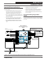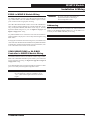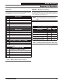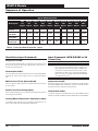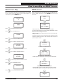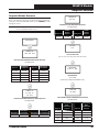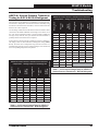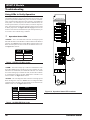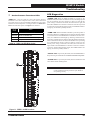
1
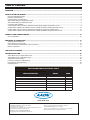
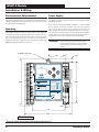
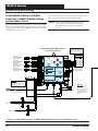
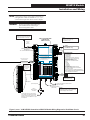
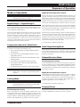
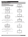
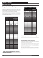
Factory Packaged Controls Water Source Heat Pump X Module Field Technical Guide YS102374 REV 0 WATTMASTER CONTROLS ALARM MADE IN USA M UP MENU ENTER www.aaon.com DOWN www.orioncontrols.com OE334-26-WSHPX-A WSHP-X MODULE NON-DIGITAL COMPRESSORS SUCT. PR. SENSOR +5V PRES 1=A1, PRES 2=A2 PRES PRES 3=B1, PRES 4=B2 GND +5 TO RED, PRES TO WHT & GND TO BLK DIGITAL COMRESSORS NOT USED PRES 1=A1, PRES 2=A2 PRES 3=B1, PRES 4=B2 +5 NOT USED, PRES TO P6 & GND TO P5 - COMP. A1 EN. - COMP. A2 EN. - COMP. B1 EN. - COMP. B2 EN. BIN 5 BIN 6 BIN 7 COM - HEAT ENABLE - WATER POF - WATER POF - COMMON T 1 - LEAVING WATER TEMP A T 2 - LEAVING WATER TEMP B GND - GROUND WattMaster Label #SW000054 Rev.: 1A E-BUS CONNECT R3 R4 ALARM OUTPUT RELAY COMMON R5 RC DIGITAL COMP. A1, A2, B1, B2 STAGE 1- COMP. A1/B1AO1 A2O STAGE 2 - COMP. A2/B2 CONNECT TO CNTLR C2 TERM. E-BUS CONNECT GND BIN 1 BIN 2 BIN 3 BIN 4 COMP. B1 ENABLE COMP. B2 ENABLE +24 VAC +5V PRES GND AAON NO.: V18330 RELAY CONTACT RATING IS 1 AMP MAX @ 24 VAC COMP. A1 ENABLE R1 COMP. A2 ENABLE R2 Table of Contents OVERVIEW ........................................................................................................................................................ 3 INSTALLATION AND WIRING ........................................................................................................................... 4 Environmental Requirements .......................................................................................................................................................4 Mounting and Dimensions ............................................................................................................................................................4 Important Wiring Considerations ..................................................................................................................................................5 Stand-Alone Wiring for Single Water Circuit ................................................................................................................................5 Stand-Alone Wiring for Dual Water Circuit ...................................................................................................................................6 Connection Wiring Details ............................................................................................................................................................7 VCM-X WSHP or SA Controller to WSHP-X Module Wiring Diagram Single Water Circuit .........................................................8 VCM-X WSHP E-BUS or SA E-BUS Controller to WSHP-X Module Wiring Single Water Circuit..............................................10 VCM-X WSHP or SA Controller to WSHP-X Module Wiring Diagram Dual Water Circuit..........................................................12 VCM-X WSHP E-BUS or SA E-BUS Controller to WSHP-X Module Wiring Dual Water Circuit ................................................14 START-UP AND COMMISSIONING.................................................................................................................. 16 Unit Configurations .....................................................................................................................................................................16 SEQUENCE OF OPERATION ........................................................................................................................... 17 WSHP-X Module Setpoints ........................................................................................................................................................17 Stand-Alone Input Commands ..................................................................................................................................................18 Input Commands (VCM-X WSHP or SA Connection) ................................................................................................................18 Modes of Operation ....................................................................................................................................................................19 LCD DISPLAY SCREENS ................................................................................................................................. 20 TROUBLESHOOTING ...................................................................................................................................... 26 Safety Monitoring for Single Water Circuit .................................................................................................................................26 Safety Monitoring for Dual Water Circuit ....................................................................................................................................27 Temperature Sensor Testing ......................................................................................................................................................28 Pressure Transducer Troubleshooting ......................................................................................................................................29 Using LEDs to Verify Operation..................................................................................................................................................30 LED Diagnostics .........................................................................................................................................................................31 PART NUMBER CROSS REFERENCE TABLE PART DESCRIPTION ORION AAON WSHP-X Module OE334-26-WSHPX-A V18330 VCM-X WSHP E-BUS Controller OE332-23E-VCMX-WSHP-A V07140 VCM-X WSHP Controller OE332-23-VCMX-WSHP-A R90810 SA E-BUS Controller OE332-23E-SA-A V07160 SA Controller OE332-23-SA-A R96070 E-BUS Distribution Module OE365-23-EBD R82930 www.aaon.com WattMaster Controls Inc. 8500 NW River Park Drive · Parkville , MO 64152 Toll Free Phone: 866-918-1100 PH: (816) 505-1100 · FAX: (816) 505-1101 · E-mail: [email protected] Visit our web site at www.orioncontrols.com WattMaster Form : AA-WSHPX-FIELD-TGD-01C Copyright December 2013 WattMaster Controls, Inc. AAON Manual Part Number: V23560 AAON® is a registered trademark of AAON, Inc., Tulsa, OK. Neither WattMaster Controls, Inc. nor AAON® assumes any responsibility for errors or omissions in this document. This document is subject to change without notice. WSHP-X Module Module Overview Overview Features The OE334-26-WSHPX-A Water Source Heat Pump X (WSHP-X) Module monitors the compressors on an AAON® Water Source Heat Pump unit and can disable the compressors based on low Suction Pressure, Leaving Water Temperature, and Water Proof of Flow inputs. It also utilizes a Delay Timer to prevent the compressors from turning on at the same time. The WSHP-X Module provides the following: Can be operated stand-alone or connected to a VCM-X WSHP Controller or SA Controller using the E-BUS Distribution Module to E-BUS interface The WSHP-X Module’s water circuit configuration can be either single or dual. There are eight R410-A glycol configurations for the WSHP-X Module—0%-40% in increments of 5%. There are two refrigerant selections—R410-A refrigerant and R-22 refrigerant. If R-22 refrigerant is selected, the glycol will automatically default to 0%. Capable of controlling digital compressors when connected to a VCM-X WSHP Series Controller or SA Series Controller Monitors suction pressure, leaving water temperature, and water proof of flow The WSHP-X Module can be used stand-alone. It can also be connected to the VCM-X WSHP Controller or the SA Controller using the E-BUS Distribution Module or the module can be directly connected to the VCM-X WSHP E-BUS Controller or SA E-BUS Controller, allowing the Module to receive setpoints from the Controllers. See chart on page 2 for part numbers. Please note: The SA series of controllers only work with the R410-A dual water circuit configurations. Can be directly connected to a VCM-X WSHP E-BUS Controller or SA E-BUS Controller Provides Delay Timer to prevent compressors from turning on at the same time Contains a 2x8 LCD character display and 4 buttons that allow for status display, setpoint changes, and configuration changes NOTE: The WSHP-X Module contains no user-serviceable parts. Contact qualified technical personnel if your Module is not operating correctly. The WSHP-X Module requires a 24 VAC power connection with an appropriate VA rating. NOTE: The WSHP-X Module is factory set for R410-A and 0% glycol. YS102374 REV 0 WATTMASTER CONTROLS ALARM MADE IN USA M UP MENU ENTER www.aaon.com DOWN www.orioncontrols.com OE334-26-WSHPX-A WSHP-X MODULE NON-DIGITAL COMPRESSORS SUCT. PR. SENSOR +5V PRES 1=A1, PRES 2=A2 PRES PRES 3=B1, PRES 4=B2 GND +5 TO RED, PRES TO WHT & GND TO BLK DIGITAL COMRESSORS NOT USED PRES 1=A1, PRES 2=A2 PRES 3=B1, PRES 4=B2 +5 NOT USED, PRES TO P6 & GND TO P5 BIN 5 BIN 6 BIN 7 COM - COMP. A1 EN. - COMP. A2 EN. - COMP. B1 EN. - COMP. B2 EN. - HEAT ENABLE - WATER POF - WATER POF - COMMON T 1 - LEAVING WATER TEMP A T 2 - LEAVING WATER TEMP B GND - GROUND WattMaster Label #SW000054 Rev.: 1A E-BUS CONNECT R3 R4 ALARM OUTPUT RELAY COMMON R5 RC DIGITAL COMP. A1, A2, B1, B2 STAGE 1- COMP. A1/B1AO1 A2O STAGE 2 - COMP. A2/B2 CONNECT TO CNTLR C2 TERM. E-BUS CONNECT GND BIN 1 BIN 2 BIN 3 BIN 4 COMP. B1 ENABLE COMP. B2 ENABLE +24 VAC +5V PRES GND AAON NO.: V18330 RELAY CONTACT RATING IS 1 AMP MAX @ 24 VAC COMP. A1 ENABLE R1 COMP. A2 ENABLE R2 Figure 1: Water Source Heat Pump X Module Technical Guide 3 WSHP-X Module Installation & Wiring Environmental Requirements Power Supply The WSHP-X Module needs to be installed in an environment that can maintain a temperature range between -30°F and 150°F and not exceed 90% RH levels (non-condensing). The WSHP-X Module requires a 24 VAC power connection with an appropriate VA rating. If you will be connecting the WSHP-X Module to a VCM-X WSHP Series Controller or SA Series Controller, one of the most important checks to make before powering up the system for the first time is to make sure that the Controller is configured properly for your application. Refer to the VCM-X Controller Technical Guide, VCM-X Modular E-BUS Controller Technical Guide, SA Controller Technical Guide, or SA E-BUS Controller Technical Guide for more information. Mounting The WSHP-X Module is housed in a plastic enclosure. It is designed to be mounted by using the 3 mounting holes in the enclosure base. It is important to mount the module in a location that is free from extreme high or low temperatures, moisture, dust, and dirt. Be careful not to damage the electronic components when mounting the module. See Figure 2 for Module dimensions (in inches). WARNING: Observe polarity! All boards must be wired GND-to-GND and 24 VAC-to-VAC. Failure to observe polarity could result in damage to the boards. 0.18 DIA. TYP. 3 PL. 2.07 0.29 WATTMASTER CONTROLS ALARM M UP ENTER MENU www.aaon.com DOWN www.orioncontrols.com OE334-26-WSHPX-A WSHP-X MODULE NON-DIGITAL COMPRESSORS SUCT. PR. SENSOR +5V PRES 1=A1, PRES 2=A2 PRES PRES 3=B1, PRES 4=B2 GND +5 TO RED, PRES TO WHT & GND TO BLK DIGITAL COMRESSORS NOT USED PRES 1=A1, PRES 2=A2 PRES 3=B1, PRES 4=B2 COMP. B1 ENABLE R3 COMP. B2 ENABLE R4 ALARM OUTPUT RELAY COMMON R5 RC +5 NOT USED, PRES TO P6 & GND TO P5 BIN 1 BIN 2 BIN 3 BIN 4 - COMP. A1 EN. - COMP. A2 EN. - COMP. B1 EN. - COMP. B2 EN. BIN 5 BIN 6 BIN 7 COM - HEAT ENABLE - WATER POF - WATER POF - COMMON CONNECT TO CNTLR C2 TERM. T 1 - LEAVING WATER TEMP A T 2 - LEAVING WATER TEMP B GND - GROUND WattMaster Label #SW000054 Rev.: 1A E-BUS CONNECT 5.05 DIGITAL COMP. A1, A2, B1, B2 STAGE 1- COMP. A1/B1AO1 A2 O STAGE 2 - COMP. A2/B2 E-BUS CONNECT GND +5V PRES GND AAON NO.: V18330 RELAY CONTACT RATING IS 1 AMP MAX @ 24 VAC COMP. A1 ENABLE R1 COMP. A2 ENABLE R2 +24 VAC 5.64 0.56 4.14 5.83 Note: Height is 1.49 inches. Figure 2: Water Source Heat Pump X Module Dimensions 4 Technical Guide WSHP-X Module Installation & Wiring Important Wiring Considerations 5. All wiring is to be in accordance with local and national electrical codes and specifications. Please read carefully and apply the following information when wiring the WSHP-X Module: 6. Check all wiring leads at the terminal block for tightness. Be sure that wire strands do not stick out and touch adjacent terminals. Confirm that all transducers required for your system are mounted in the appropriate location and wired into the correct terminals. 1. To operate the WSHP-X Module in Stand-Alone mode, you must connect power to the 24 VAC input terminal block. Do not allow wire strands to stick out and touch adjoining terminals. This could potentially cause a short circuit. 2. The 1 to 5 VDC signals for the Compressor modulation need to use 18-gauge shielded twisted pair cable, and the Drain wire must be the GND signal. Stand-Alone Wiring Single Water Circuit 3. All 24 VAC wiring must be connected so that all ground wires remain common. Failure to follow this procedure can result in damage to the module and connected devices. To operate the WSHP-X Module as Stand Alone, connect the Module to a 24 VAC power connection with an appropriate VA rating. See Figure 3 for wiring. 4. Be sure all modular wiring harness connectors are seated firmly in their respective modular connectors on the circuit board. OE334-36-WSHPX-A Water Source Heat Pump X Module NOTE: ALL RELAY OUTPUTS ARE NORMALLY OPEN AND RATED FOR 24 VAC POWER ONLY - 1 AMP MAXIMUM LOAD CIRCUIT A SUCTION PRESSURE TRANSDUCER +V SIG 1 BK GND WATTMASTER CONTROLS ALARM CIRCUIT B SUCTION PRESSURE TRANSDUCER M +V SIG 1 BK GND MENU DOWN OE334-26-WSHPX-A WSHP-X MODULE NON-DIGITAL COMPRESSORS SUCT. PR. SENSOR +5V PRES 1=A1, PRES 2=A2 PRES PRES 3=B1, PRES 4=B2 GND COMPRESSOR A1 ENABLE CONTACT COMPRESSOR A2 ENABLE CONTACT COMPRESSOR B1 ENABLE CONTACT COMPRESSOR B2 ENABLE CONTACT HEAT ENABLE CONTACT WATER POF SYSTEM A CONTACT WATER POF SYSTEM B CONTACT BIN1 BIN2 BIN3 BIN4 BIN5 BIN6 BIN7 COM T1 ENTER www.aaon.com www.orioncontrols.com +5 TO RED, PRES TO WHT & GND TO BLK +5V PRES GND DIGITAL COMRESSORS NOT USED PRES 1=A1, PRES 2=A2 PRES 3=B1, PRES 4=B2 +5 NOT USED, PRES TO P6 & GND TO P5 BIN 1 - COMP. A1 EN. BIN 2 - COMP. A2 EN. BIN 3 - COMP. B1 EN. BIN 4 - COMP. B2 EN. BIN 5 - HEAT ENABLE BIN 6 - WATER POF BIN 7 - WATER POF COM - COMMON E-BUS CONNECT AAON NO.: V18330 COMPRESSOR A1 ENABLE OUTPUT COMPRESSOR A2 ENABLE OUTPUT COMPRESSOR B1 ENABLE OUTPUT COMPRESSOR B2 ENABLE OUTPUT ALARM OUTPUT HVAC UNIT CONNECTIONS COMP. B1 ENABLE R3 COMP. B2 ENABLE R4 ALARM OUTPUT RELAY COMMON R5 RC DIGITAL COMP. A1, A2, B1, B2 STAGE 1- COMP. A1/B1AO1 A2O STAGE 2 - COMP. A2/B2 NOTE: OUTPUTS ARE NOT USED ON STAND ALONE APPLICATIONS CONNECT TO CNTLR C2 TERM. T 1 - LEAVING WATER TEMP A T 2 - LEAVING WATER TEMP B GND - GROUND WattMaster Label #SW000054 Rev.: 1A R1 R2 R3 R4 R5 COMM RELAY CONTACT RATING IS 1 AMP MAX @ 24 VAC COMP. A1 ENABLE R1 COMP. A2 ENABLE R2 E-BUS CONNECT GND RD WH UP +24 VAC RD WH GND 24 VAC GND E R LEAVING WATER TEMPERATURE Figure 3: Water Source Heat Pump X Module as Stand-Alone for Single Water Circuit Technical Guide 5 WSHP-X Module Installation & Wiring Stand-Alone Wiring Dual Water Circuit To operate the WSHP-X Module as Stand Alone, connect the Module to a 24 VAC power connection with an appropriate VA rating. See Figure 4 for wiring. OE334-43-WSHPX-A Water Source Heat Pump X Module +V SIG 1 CIRCUIT A2 SUCTION PRESSURE TRANSDUCER RD WH BK +V SIG 2 GND CIRCUIT B1 SUCTION PRESSURE TRANSDUCER RD WH BK +V SIG 1 GND CIRCUIT B2 SUCTION PRESSURE TRANSDUCER RD WH +V SIG 2 BK GND WATTMASTER CONTROLS GND ALARM M MENU DOWN www.orioncontrols.com OE334-26-WSHPX-A WSHP-X MODULE NON-DIGITAL COMPRESSORS SUCT. PR. SENSOR +5V PRES 1=A1, PRES 2=A2 PRES PRES 3=B1, PRES 4=B2 GND +5V PRES GND +5 NOT USED, PRES TO P6 & GND TO P5 BIN 5 - HEAT ENABLE BIN 6 - WATER POF BIN 7 - WATER POF COM - COMMON E-BUS CONNECT COMP. B1 ENABLE R3 COMP. B2 ENABLE R4 ALARM OUTPUT RELAY COMMON R5 RC DIGITAL COMP. A1, A2, B1, B2 STAGE 1- COMP. A1/B1AO1 A2O STAGE 2 - COMP. A2/B2 COMPRESSOR A1 ENABLE COMPRESSOR A2 ENABLE COMPRESSOR B1 ENABLE COMPRESSOR B2 ENABLE ALARM OUTPUT HVAC UNIT CONNECTIONS NOTE: OUTPUTS ARE NOT USED ON STAND ALONE APPLICATIONS CONNECT TO CNTLR C2 TERM. T 1 - LEAVING WATER TEMP A T 2 - LEAVING WATER TEMP B GND - GROUND WattMaster Label #SW000054 Rev.: 1A AAON NO.: V18330 RELAY CONTACT RATING IS 1 AMP MAX @ 24 VAC COMP. A1 ENABLE R1 COMP. A2 ENABLE R2 DIGITAL COMRESSORS NOT USED PRES 1=A1, PRES 2=A2 PRES 3=B1, PRES 4=B2 BIN 1 - COMP. A1 EN. BIN 2 - COMP. A2 EN. BIN 3 - COMP. B1 EN. BIN 4 - COMP. B2 EN. R1 R2 R3 R4 R5 COMM E-BUS CONNECT GND 24 VAC BIN1 BIN2 BIN3 BIN4 BIN5 BIN6 BIN7 COM T1 T2 GND ENTER www.aaon.com +5 TO RED, PRES TO WHT & GND TO BLK COMPRESSOR A1 ENABLE CONTACT COMPRESSOR A2 ENABLE CONTACT COMPRESSOR B1 ENABLE CONTACT COMPRESSOR B2 ENABLE CONTACT HEAT ENABLE CONTACT WATER POF SYSTEM A CONTACT WATER POF SYSTEM B CONTACT UP GND RD WH BK +24 VAC CIRCUIT A1 SUCTION PRESSURE TRANSDUCER NOTE: ALL RELAY OUTPUTS ARE NORMALLY OPEN AND RATED FOR 24 VAC POWER ONLY - 1 AMP MAXIMUM LOAD E R LEAVING WATER TEMPERATURE FOR SYSTEM A LEAVING WATER TEMPERATURE FOR SYSTEM B Figure 4: Water Source Heat Pump X Module as Stand-Alone for Dual Water Circuit 6 Technical Guide WSHP-X Module Installation & Wiring E-BUS to WSHP-X Module Wiring The WSHP-X Module connects to the E-BUS Distribution Module using a modular HSSC cable. The WSHP-X Module requires a 24 VAC power connection with an appropriate VA rating. The E-BUS Distribution Module connects to the VCM-X WSHP Controller, VCM-X Expansion Module, SA Controller (Dual Water Circuit only), SA Expansion Module (Dual Water Circuit only), or 12 Relay Expansion Module using the I2C port. See Figure 5 on page 8 and Figure 7 on page 12 for wiring. Any E-BUS Module can be connected to each of the four E-BUS Distribution Module’s output ports or can be daisy-chained together using HSSC cables. WARNING: Be sure all controllers and modules are powered down before connecting or disconnecting HSSC cables. Addressing When the WSHP-X Module is connected to the E-BUS Distribution Module, set the WSHP-X Module’s address to 1. Set the address consecutively for each WSHP-X Module you are using. NOTE: Address zero defaults to address 1. If using a spliced terminal connection for longer runs, one module can be connected to the E-BUS Distribution Module and any additional modules would be daisy-chained to the first module. For more information, refer to the E-BUS Distribution Module Technical Guide. VCM-X WSHP E-BUS or SA E-BUS Controller to WSHP-X Module Wiring The WSHP-X Module connects to the E-BUS Controller using a modular HSSC cable. The WSHP-X Module requires a 24 VAC power connection with an appropriate VA rating. See Figure 6 on page 10 and Figure 8 on page 14 for wiring. Any E-BUS Module can be connected to the E-BUS Controller’s E-BUS port or can be daisy-chained together using HSSC cables. NOTE: Contact Factory for the correct HSSC cable length for your application. Cables are available in 1/4, 1/2, 1, 2, 3, 4, and 5 Meter lengths and 100 and 150 Foot lengths. Technical Guide 7 WSHP-X Module Installation & Wiring VCM-X WSHP to WSHP-X Module Wiring for Single Water Circuit The VCM-X WSHP Controller or SA Controller communicates with the WSHP-X Module using the E-BUS Distribution Module. See Figure 5 for wiring details. For Stand Alone Applications, Connect To System Manager. For Network Applications Connect To Next Controller And/Or MiniLink PD On Local Loop. NOTE: When using the WSHP-X Module, all compressors will be wired from the WSHP-X Module, not the VCM-X WSHP Controller Note: All Relay Outputs Are Normally Open And Rated For 24 VAC Power Only. 1 Amp Maximum Load. (OE332-23-WSHP-C) VCM-X WSHP Controller Local Loop RS-485 9600 Baud R - 24VAC G - Fan ON/OFF Only All Comm Loop Wiring Is Straight Thru T to T, R to R & SHLD to SHLD Relay Output Contacts R2 Through R5 May Be User Configured For The Following: 1 - Heating Stages 2 - See Note 1 Below 3 - Warm-up Mode Command (VAV Boxes) 4 - Reversing Valve (Air To Air Heat Pumps) 5 - Reheat Control (Dehumidification) 6 - Exhaust Fan Interlock 7 - Preheater For Low Ambient Protection 8 - Alarm 9 - Override 10 - Occupied 11 - OA Damper 12 - Heat Wheel Note: 1.) When Using The WSHP-X Module, All Compressors Will Be Wired From The Module, Not The VCM-X Controller. 2.) A Total Of 20 Relays Are Available By Adding Relay Expansion Modules. All Expansion Module Relay Outputs Are User-Configurable As Listed Above. See Individual Component Wiring Diagrams For Detailed Wiring Of Analog Inputs And Outputs AI1 SET AI5 AI4 SET AI5 SET AI2 SET AI7 AI3 SET AI4 AI2 SET AI1 SET AI1 AI2 AI3 Connect To E-BUS Distribution Module GND Line Voltage AI7 SET AI3 SET 24VAC 24 VAC GND AI4 SET Size Transformer For Correct Total Load. VCM-X Controller = 8 VA Jumpers AI5 SET Splice If Required AI7 SET OE271 Static Pressure Transducer Connect FRP Tubing To High Pressure Port (Bottom Tube) And Route To Static Pressure Pickup Probe Located In Unit Discharge. Leave Port Marked “Lo” Open To Atmosphere Line Voltage Connect To Digital Room Sensor And/Or Digital CO2 Sensor Connect To E-BUS Distribution Module or Expansion Module(s) (When Used) Warning: 24 VAC Must Be Connected So That All Ground Wires Remain Common. Failure To Do So Will Result In Damage To The Controllers. Figure 5: VCM-X WSHP Controller to WSHP-X Module Wiring Diagram for Single Water Circuit 8 Technical Guide WSHP-X Module Installation & Wiring CIRCUIT B SUCTION PRESSURE TRANSDUCER BK WH RD CIRCUIT A SUCTION PRESSURE TRANSDUCER BK WH RD OE334-26-WSHPX-A Water Source Heat Pump X Module NOTE: ALL RELAY OUTPUTS ARE NORMALLY OPEN AND RATED FOR 24 VAC POWER ONLY OE365-23-EBD E-BUS Distribution Module HVAC UNIT CONNECTIONS YS102374 REV 0 WATTMASTER CONTROLS ALARM MADE IN USA M YS102308 REV 1 I2C TO COMM DIST. BOARD UP MENU ENTER www.aaon.com +COMM DOWN www.orioncontrols.com SHLD OE334-26-WSHPX-A WSHP-X MODULE -COMM NON-DIGITAL COMPRESSORS SUCT. PR. SENSOR +5V PRES 1=A1, PRES 2=A2 PRES PRES 3=B1, PRES 4=B2 GND +VDC +5 TO RED, PRES TO WHT & GND TO BLK +5V PRES GND INPUT DIGITAL COMRESSORS NOT USED PRES 1=A1, PRES 2=A2 PRES 3=B1, PRES 4=B2 +5 NOT USED, PRES TO P6 & GND TO P5 +COMM BIN 1 BIN 2 BIN 3 BIN 4 SHLD WATER POF CONTACT -COMM GND BIN6 BIN 5 BIN 6 BIN 7 COM - HEAT ENABLE - WATER POF - WATER POF - COMMON T 1 - LEAVING WATER TEMP A T 2 - LEAVING WATER TEMP B GND - GROUND COM 24VAC - COMP. A1 EN. - COMP. A2 EN. - COMP. B1 EN. - COMP. B2 EN. WattMaster Label #SW000054 Rev.: 1A T1 E-BUS CONNECT AAON NO.: V18330 RELAY CONTACT RATING IS 1 AMP MAX @ 24 VAC COMP. A1 ENABLE R1 COMP. A2 ENABLE R2 COMP. B1 ENABLE R3 COMP. B2 ENABLE R4 ALARM OUTPUT RELAY COMMON R5 RC AO1 DIGITAL STAGE 1 (1.5-5V) AO2 DIGITAL STAGE 2 (1.5-5V) DIGITAL COMP. A1, A2, B1, B2 STAGE 1- COMP. A1/B1AO1 A2O STAGE 2 - COMP. A2/B2 CONNECT TO CNTLR C2 TERM. E-BUS CONNECT GND GND COMP. A1 ENABLE COMP. A2 ENABLE COMP. B1 ENABLE COMP. B2 ENABLE ALARM OUTPUT +24 VAC OUTPUT R1 R2 R3 R4 R5 COMM GND GND 485 DRV WARNING!! Observe Polarity! All boards must be wired with GND-to-GND and 24 VACto-24 VAC. Failure to observe polarity could result in damage to the boards. HSSC Cable Modular Cable Connect To VCM-X WSHP Controller HSSC Cable Connect To Other WattMaster-Approved E-BUS Expansion Module(s) 24 VAC GND PWR 24 VAC Transformer 3 VA Minimum E WARNING!! Observe Polarity! All boards must be wired with GND-to-GND and 24 VAC-to-24 VAC. Failure to observe polarity could result in damage to the boards. LEAVING WATER TEMPERATURE Figure 5, cont.: VCM-X WSHP Controller to WSHP-X Module Wiring Diagram for Single Water Circuit Technical Guide 9 WSHP-X Module Installation & Wiring VCM-X WSHP E-BUS or SA E-BUS Controller to WSHP-X Module Wiring for Single Water Circuit Any E-BUS Module can be connected to the E-BUS Controller’s E-BUS port or can be daisy-chained together using HSSC cables. NOTE: When using the WSHP-X Module, all compressors will be wired from the WSHP-X Module, not the VCM-X WSHP E-BUS Controller. The WSHP-X Module connects to the E-BUS Controller using a modular HSSC cable. The WSHP-X Module requires a 24 VAC power connection with an appropriate VA rating. See Figure 6 below for wiring. OE334-26-WSHPX-A Water Source Heat Pump X Module HVAC UNIT CONNECTIONS +V SIG 1 GND YS102374 REV 0 WATTMASTER CONTROLS ALARM MADE IN USA M RD WH BK MENU +V SIG 1 GND DOWN www.orioncontrols.com OE334-26-WSHPX-A WSHP-X MODULE NON-DIGITAL COMPRESSORS SUCT. PR. SENSOR +5V PRES 1=A1, PRES 2=A2 PRES PRES 3=B1, PRES 4=B2 GND +5 TO RED, PRES TO WHT & GND TO BLK DIGITAL COMRESSORS +5V NOT USED PRES PRES 1=A1, PRES 2=A2 GND PRES 3=B1, PRES 4=B2 +5 NOT USED, PRES TO P6 & GND TO P5 BIN 1 BIN 2 BIN 3 BIN 4 WARNING!! Observe Polarity! All boards must be wired with GNDto-GND and 24 VAC-to-24 VAC. Failure to observe polarity could result in damage to the boards. BIN6 - COMP. A1 EN. - COMP. A2 EN. - COMP. B1 EN. - COMP. B2 EN. BIN 5 - HEAT ENABLE BIN 6 - WATER POF BIN 7 - WATER POF COM - COMMON T 1 - LEAVING WATER TEMP A T 2 - LEAVING WATER TEMP B GND - GROUND COM T1 WattMaster Label #SW000054 Rev.: 1A E-BUS CONNECT R1 R2 R3 R4 R5 COMM COMP. A1 ENABLE COMP. A2 ENABLE COMP. B1 ENABLE COMP. B2 ENABLE ALARM OUTPUT AAON NO.: V18330 RELAY CONTACT RATING IS 1 AMP MAX @ 24 VAC COMP. A1 ENABLE R1 COMP. A2 ENABLE R2 COMP. B1 ENABLE R3 COMP. B2 ENABLE R4 ALARM OUTPUT RELAY COMMON R5 RC AO1 DIGITAL STG 1 (1.5-5V) AO2 DIGITAL STG 2 (1.5-5V) DIGITAL COMP. A1, A2, B1, B2 STAGE 1- COMP. A1/B1AO1 A2O STAGE 2 - COMP. A2/B2 CONNECT TO CNTLR C2 TERM. E-BUS CONNECT GND WATER POF ENTER www.aaon.com GND CIRCUIT B SUCTION PRESSURE TRANSDUCER UP GND 24 VAC RD WH BK +24 VAC CIRCUIT A SUCTION PRESSURE TRANSDUCER NOTE: ALL RELAY OUTPUTS ARE NORMALLY OPEN AND RATED FOR 24 VAC POWER ONLY Line Voltage Connect To Other WattMaster-Approved E-BUS Expansion Module(s) 24 VAC Transformer 3 VA Minimum HSSC Cable E WARNING!! Observe Polarity! All boards must be wired with GND-to-GND and 24 VAC-to-24 VAC. Failure to observe polarity could result in damage to the boards. HSSC Cable Connect To VCM-X WSHP E-BUS Controller LEAVING WATER TEMPERATURE Figure 6: VCM-X E-BUS Controller to WSHP-X Module Wiring Diagram for Single Water Circuit 10 Technical Guide WSHP-X Module Installation & Wiring NOTE: Contact Factory for the correct HSSC cable length for your application. Cables are available in ¼, ½, 1, 2, 3, 4, and 5 Meter lengths and 100 and 150 Foot lengths. WARNING: Be sure all controllers and modules are powered down before connecting or disconnecting HSSC cables. For Stand Alone Applications, Connect To System Manager. For Network Applications Connect To Next Controller And/Or MiniLink PD On Local Loop. OE332-23E-VCMX-WSHP VCM-X Modular E-BUS Controller Note: All Relay Outputs Are Normally Open And Rated For 24 VAC Power Only. 1 Amp Maximum Load. Local Loop RS-485 9600 Baud RS-485 COMMUNICATION LOOP. WIRE “R” TO “R”, “T” TO “T” “SHLD” TO “SHLD” R - 24VAC RELAY CONTACT RATING IS 1 AMP MAX @ 24 VAC G - Fan ON/OFF Only RELAY COMMON All Comm Loop Wiring Is Straight Thru T to T, R to R & SHLD to SHLD FAN RELAY 2 RELAY 3 RELAY 4 RELAY 5 Relay Output Contacts R2 Through R5 May Be User-Configured For The Following: 1 - Heating Stages 2 - Cooling Stages 3 - Warm-up Mode Command (VAV Boxes) 4 - Reversing Valve (Air To Air Heat Pumps) 5 - Reheat Control (Dehumidification) 6 - Exhaust Fan Interlock 7 - Preheater For Low Ambient Protection 8 - Alarm 9 - Override 10 - Occupied 11 - OA Damper 12 - Heat Wheel 13 - Emergency Heat Note: 1.) When Using the WSHP-X Module, All Compressors Will Be Wired From the Module, Not the VCM-X Controller. 2.) A Total Of 20 Relays Are Available By Adding Relay Expansion Modules. All Expansion Module Relay Outputs Are User Configurable As Listed Above. AAON No.: V07150 VCM-X MODULAR E-BUS CONTROLLER Orion No.:OE332-23E-VCMX-MOD-A AI1 = SPC (SPACE TEMPERATURE SENSOR) AI2 = SAT (SUPPLY AIR TEMPERATURE SENSOR) AI3 = RAT (RETURN AIR TEMPERATURE SENSOR) AI4 = OAT (OUTDOOR AIR TEMPERATURE SENSOR) AI5 = SUCTION PRESSURE SENSOR (FROM EXP. MODULE) AI7 = SPACE TEMPERATURE SENSOR SLIDE ADJUST OR VOLTAGE RESET SOURCE A01 = ECONOMIZER (2-10 VDC OUTPUT) A02 = SUPPLY FAN VFD (0-10 VDC OUTPUT) HSSC Cable Connect To VCM-X E-BUS Port E-BUS CONNECTOR ANALOG INPUT JUMPER SETTINGS AI1 SET See Individual Component Wiring Diagrams For Detailed Wiring Of Analog Inputs And Outputs AI2 SET STATUS1 STATUS2 0 1 SAT FAIL 1 2 OAT FAIL 2 2 SPC FAIL 3 2 MODULE ALARM 4 2 MECH COOL FAIL 1 3 MECH HEAT FAIL 2 3 FAN PROOF FAIL 3 3 THERM 4-20mA 0-10V 0-5V DIRTY FILTER 4 3 EMERGENCY SHUTDOWN 5 3 LOW SAT 1 4 THERM 4-20mA 0-10V 0-5V HIGH SAT THERM 4-20mA 0-10V 0-5V PUSH BUTTON OVR THERM 4-20mA 0-10V 0-5V AI2 THERM 4-20mA 0-10V 0-5V THERM 4-20mA 0-10V 0-5V AI4 AI5 AI3 AI7 LED BLINK CODES NORMAL OPERATION AI1 LED NAME 4 3 4 CONT. TEMP HEAT FAIL 4 4 1 5 ZONE OVR 2 5 OUTPUT FORCE ACTIVE 0 6 AI3 SET ANALOG INPUT JUMPER SETTINGS MUST BE SET AS SHOWN FOR PROPER OPERATION STATIC PRESSURE 2 CONT. TEMP COOL FAIL WattMaster Label #LB102073-01-A Rev.: 1A GND 24 VAC POWER ONLY WARNING! POLARITY MUST BE OBSERVED OR THE CONTROLLER WILL BE DAMAGED 2 IC EXPANSION 2 IC DIGITAL SENSOR Line Voltage 24VAC AI4 SET Size Transformer For Correct Total Load. VCM-X Controller = 8 VA Jumpers AI5 SET Splice If Required AI7 SET OE271 Static Pressure Transducer Connect To Digital Room Sensor And/Or Digital CO2 Sensor Connect To Expansion Module(s) (When Used) Warning: 24 VAC Must Be Connected So That All Ground Wires Remain Common. Failure To Do So Will Result In Damage To The Controllers. Connect FRP Tubing To High Pressure Port (Bottom Tube) And Route To Static Pressure Pickup Probe Located In Unit Discharge. Leave Port Marked “Lo” Open To Atmosphere. Figure 6, cont.: VCM-X E-BUS Controller to WSHP-X Module Wiring Diagram for Single Water Circuit Technical Guide 11 WSHP-X Module Installation & Wiring VCM-X WSHP or SA Controller to WSHP-X Module Wiring for Dual Water Circuit NOTE: When using the WSHP-X Module, all compressors will be wired from the WSHP-X Module, not the VCM-X WSHP Controller or SA Controller. The VCM-X WSHP Controller or SA Controller communicates with the WSHP-X Module using the E-BUS Distribution Module. See Figure 7 for wiring details (VCM-X WSHP Controller shown). For Stand Alone Applications, Connect To System Manager. For Network Applications Connect To Next Controller And/Or MiniLink PD On Local Loop. (OE332-23-WSHP-A) VCM-X WSHP Controller Note: All Relay Outputs Are Normally Open And Rated For 24 VAC Power Only. 1 Amp Maximum Load. Local Loop RS-485 9600 Baud R - 24VAC G - Fan ON/OFF Only All Comm Loop Wiring Is Straight Thru T to T, R to R & SHLD to SHLD Relay Output Contacts R2 Through R5 May Be User Configured For The Following: 1 - Heating Stages 2 - See Note 1 Below 3 - Warm-up Mode Command (VAV Boxes) 4 - Reversing Valve (Air To Air Heat Pumps) 5 - Reheat Control (Dehumidification) 6 - Exhaust Fan Interlock 7 - Preheater For Low Ambient Protection 8 - Alarm 9 - Override 10 - Occupied 11 - OA Damper 12 - Heat Wheel Note: 1.) When Using the WSHP-X Module, All Compressors Will Be Wired From the Module, Not the VCM-X Controller. 2.) A Total Of 20 Relays Are Available By Adding Relay Expansion Modules. All Expansion Module Relay Outputs Are User Configurable As Listed Above. See Individual Component Wiring Diagrams For Detailed Wiring Of Analog Inputs And Outputs AI1 SET AI5 AI4 SET AI5 SET AI2 SET AI7 AI3 SET AI4 AI2 SET AI1 SET AI1 AI2 AI3 GND Line Voltage AI7 SET AI3 SET 24VAC Connect To E-BUS Distribution Module 24 VAC GND Size Transformer For Correct Total Load. VCM-X Controller = 8 VA AI4 SET Jumpers AI5 SET Splice If Required AI7 SET OE271 Static Pressure Transducer Connect FRP Tubing To High Pressure Port (Bottom Tube) And Route To Static Pressure Pickup Probe Located In Unit Discharge. Leave Port Marked “Lo” Open To Atmosphere Connect To Digital Room Sensor And/Or Digital CO2 Sensor Line Voltage Connect To E-BUS Distribution Module Or Expansion Module(s) (When Used) Warning: 24 VAC Must Be Connected So That All Ground Wires Remain Common. Failure To Do So Will Result In Damage To The Controllers. Figure 7: VCM-X WSHP Controller to WSHP-X Module Wiring Diagram for Dual Water Circuit 12 Technical Guide WSHP-X Module Installation & Wiring CIRCUIT B2 SUCTION PRESSURE TRANSDUCER BK WH RD CIRCUIT B1 SUCTION PRESSURE TRANSDUCER BK WH RD CIRCUIT A2 SUCTION PRESSURE TRANSDUCER BK WH RD CIRCUIT A1 SUCTION PRESSURE TRANSDUCER BK WH RD OE334-26-WSHPX-A Water Source Heat Pump X Module NOTE: ALL RELAY OUTPUTS ARE NORMALLY OPEN AND RATED FOR 24 VAC POWER ONLY OE365-23-EBD E-BUS Distribution Module HVAC UNIT CONNECTIONS YS102374 REV 0 WATTMASTER CONTROLS ALARM MADE IN USA M YS102308 REV 1 I2C TO COMM DIST. BOARD UP MENU ENTER www.aaon.com +COMM DOWN www.orioncontrols.com OE334-26-WSHPX-A WSHP-X MODULE -COMM NON-DIGITAL COMPRESSORS SUCT. PR. SENSOR +5V PRES 1=A1, PRES 2=A2 PRES PRES 3=B1, PRES 4=B2 GND +VDC +5 TO RED, PRES TO WHT & GND TO BLK DIGITAL COMRESSORS +5V NOT USED PRES PRES 1=A1, PRES 2=A2 GND PRES 3=B1, PRES 4=B2 INPUT +5 NOT USED, PRES TO P6 & GND TO P5 +COMM BIN 1 BIN 2 BIN 3 BIN 4 SHLD -COMM WATER POF A WATER POF B GND 24VAC GND PWR BIN6 BIN7 COM T1 T2 - COMP. A1 EN. - COMP. A2 EN. - COMP. B1 EN. - COMP. B2 EN. BIN 5 BIN 6 BIN 7 COM - HEAT ENABLE - WATER POF - WATER POF - COMMON T 1 - LEAVING WATER TEMP A T 2 - LEAVING WATER TEMP B GND - GROUND WattMaster Label #SW000054 Rev.: 1A E-BUS CONNECT AAON NO.: V18330 RELAY CONTACT RATING IS 1 AMP MAX @ 24 VAC COMP. A1 ENABLE R1 COMP. A2 ENABLE R2 COMP. B1 ENABLE R3 COMP. B2 ENABLE R4 ALARM OUTPUT RELAY COMMON R5 RC AO1 DIGITAL STG 1 (1.5-5V) AO2 DIGITAL STG 2 (1.5-5V) DIGITAL COMP. A1, A2, B1, B2 STAGE 1- COMP. A1/B1AO1 A2O STAGE 2 - COMP. A2/B2 CONNECT TO CNTLR C2 TERM. E-BUS CONNECT GND SHLD GND COMP. A1 ENABLE COMP. A2 ENABLE COMP. B1 ENABLE COMP. B2 ENABLE ALARM OUTPUT +24 VAC OUTPUT R1 R2 R3 R4 R5 COMM GND GND 24 VAC 485 DRV Line Voltage WARNING!! Observe Polarity! All boards must be wired with GND-toGND and 24 VAC-to-24 VAC. Failure to observe polarity could result in damage to the boards. HSSC Cable Modular Cable Connect To VCM-X WSHP Controller HSSC Cable Connect To Other WattMaster-Approved E-BUS Expansion Module(s) 24 VAC Transformer 3 VA Minimum E WARNING!! Observe Polarity! All boards must be wired with GND-to-GND and 24 VAC-to-24 VAC. Failure to observe polarity could result in damage to the boards. LEAVING WATER TEMPERATURE FOR SYSTEM A LEAVING WATER TEMPERATURE FOR SYSTEM B Figure 7, cont.: VCM-X WSHP Controller to WSHP-X Module Wiring Diagram for Dual Water Circuit Technical Guide 13 WSHP-X Module Installation and Wiring VCM-X WSHP E-BUS or SA E-BUS Controller to WSHP-X Module Wiring for Dual Water Circuit Any E-BUS Module can be connected to the E-BUS Controller’s E-BUS port or can be daisy-chained together using HSSC cables. NOTE: When using the WSHP-X Module, all compressors will be wired from the WSHP-X Module, not the VCM-X WSHP E-BUS Controller or SA E-BUS Controller. The WSHP-X Module connects to the E-BUS Controller using a modular HSSC cable. The WSHP-X Module requires a 24 VAC power connection with an appropriate VA rating. See Figure 8 below for wiring. (VCM-X WSHP E-BUS Controller shown.) OE334-26-WSHPX-A Water Source Heat Pump X Module CIRCUIT A2 SUCTION PRESSURE TRANSDUCER RD WH BK +V SIG 2 GND CIRCUIT B1 SUCTION PRESSURE TRANSDUCER RD WH BK +V SIG 1 GND CIRCUIT B2 SUCTION PRESSURE TRANSDUCER RD WH BK +V SIG 2 GND HVAC UNIT CONNECTIONS YS102374 REV 0 WATTMASTER CONTROLS ALARM MADE IN USA M MENU DOWN www.orioncontrols.com OE334-26-WSHPX-A WSHP-X MODULE NON-DIGITAL COMPRESSORS SUCT. PR. SENSOR +5V PRES 1=A1, PRES 2=A2 PRES PRES 3=B1, PRES 4=B2 GND +5V PRES GND DIGITAL COMRESSORS NOT USED PRES 1=A1, PRES 2=A2 PRES 3=B1, PRES 4=B2 +5 NOT USED, PRES TO P6 & GND TO P5 BIN 1 - COMP. A1 EN. BIN 2 - COMP. A2 EN. BIN 3 - COMP. B1 EN. BIN 4 - COMP. B2 EN. BIN6 BIN7 COM T1 T2 BIN 5 - HEAT ENABLE BIN 6 - WATER POF BIN 7 - WATER POF COM - COMMON T 1 - LEAVING WATER TEMP A T 2 - LEAVING WATER TEMP B GND - GROUND WattMaster Label #SW000054 Rev.: 1A E-BUS CONNECT R1 R2 R3 R4 R5 COMM COMP. A1 ENABLE COMP. A2 ENABLE COMP. B1 ENABLE COMP. B2 ENABLE ALARM OUTPUT AAON NO.: V18330 RELAY CONTACT RATING IS 1 AMP MAX @ 24 VAC COMP. A1 ENABLE R1 COMP. A2 ENABLE R2 COMP. B1 ENABLE R3 COMP. B2 ENABLE R4 ALARM OUTPUT RELAY COMMON R5 RC AO1 DIGITAL STG 1 (1.5-5V) AO2 DIGITAL STG 2 (1.5-5V) DIGITAL COMP. A1, A2, B1, B2 STAGE 1- COMP. A1/B1AO1 A2O STAGE 2 - COMP. A2/B2 CONNECT TO CNTLR C2 TERM. E-BUS CONNECT GND WARNING!! Observe Polarity! All boards must be wired with GND-toGND and 24 VAC-to-24 VAC. Failure to observe polarity could result in damage to the boards. ENTER www.aaon.com +5 TO RED, PRES TO WHT & GND TO BLK WATER POF A WATER POF B UP GND 24 VAC +V SIG 1 GND GND RD WH BK +24 VAC CIRCUIT A1 SUCTION PRESSURE TRANSDUCER NOTE: ALL RELAY OUTPUTS ARE NORMALLY OPEN AND RATED FOR 24 VAC POWER ONLY Line Voltage Connect To Other WattMaster-Approved E-BUS Expansion Module(s) 24 VAC Transformer 3 VA Minimum HSSC Cable E WARNING!! Observe Polarity! All boards must be wired with GND-to-GND and 24 VAC-to-24 VAC. Failure to observe polarity could result in damage to the boards. HSSC Cable Connect To VCM-X E-BUS Controller or SA E-BUS Controller LEAVING WATER TEMPERATURE FOR SYSTEM A LEAVING WATER TEMPERATURE FOR SYSTEM B Figure 8: VCM-X E-BUS Controller to WSHP-X Module Wiring Diagram for Dual Water Circuit 14 Technical Guide WSHP-X Module Installation and Wiring NOTE: Contact Factory for the correct HSSC cable length for your application. Cables are available in ¼, ½, 1, 2, 3, 4, and 5 Meter lengths and 100 and 150 Foot lengths. WARNING: Be sure all controllers and modules are powered down before connecting or disconnecting HSSC cables. For Stand Alone Applications, Connect To System Manager. For Network Applications Connect To Next Controller And/Or MiniLink PD On Local Loop. Note: All Relay Outputs Are Normally Open And Rated For 24 VAC Power Only. 1 Amp Maximum Load. OE332-23E-VCMX-WSHP VCM-X Modular E-BUS Controller Local Loop RS-485 9600 Baud RS-485 COMMUNICATION LOOP. WIRE “R” TO “R”, “T” TO “T” “SHLD” TO “SHLD” R - 24VAC RELAY CONTACT RATING IS 1 AMP MAX @ 24 VAC G - Fan ON/OFF Only RELAY COMMON All Comm Loop Wiring Is Straight Thru T to T, R to R & SHLD to SHLD FAN RELAY 2 RELAY 3 RELAY 4 RELAY 5 Relay Output Contacts R2 Through R5 May Be User-Configured For The Following: 1 - Heating Stages 2 - Cooling Stages 3 - Warm-up Mode Command (VAV Boxes) 4 - Reversing Valve (Air To Air Heat Pumps) 5 - Reheat Control (Dehumidification) 6 - Exhaust Fan Interlock 7 - Preheater For Low Ambient Protection 8 - Alarm 9 - Override 10 - Occupied 11 - OA Damper 12 - Heat Wheel 13 - Emergency Heat Note: 1.) When Using the WSHP-X Module, All Compressors Will Be Wired From the Module, Not the VCM-X Controller. 2.) A Total Of 20 Relays Are Available By Adding Relay Expansion Modules. All Expansion Module Relay Outputs Are User Configurable As Listed Above. AAON No.: V07150 VCM-X MODULAR E-BUS CONTROLLER Orion No.:OE332-23E-VCMX-MOD-A AI1 = SPC (SPACE TEMPERATURE SENSOR) AI2 = SAT (SUPPLY AIR TEMPERATURE SENSOR) AI3 = RAT (RETURN AIR TEMPERATURE SENSOR) AI4 = OAT (OUTDOOR AIR TEMPERATURE SENSOR) AI5 = SUCTION PRESSURE SENSOR (FROM EXP. MODULE) AI7 = SPACE TEMPERATURE SENSOR SLIDE ADJUST OR VOLTAGE RESET SOURCE A01 = ECONOMIZER (2-10 VDC OUTPUT) A02 = SUPPLY FAN VFD (0-10 VDC OUTPUT) HSSC Cable Connect To VCM-X E-BUS Port E-BUS CONNECTOR ANALOG INPUT JUMPER SETTINGS AI1 SET See Individual Component Wiring Diagrams For Detailed Wiring Of Analog Inputs And Outputs AI1 THERM 4-20mA 0-10V 0-5V LED BLINK CODES STATUS1 STATUS2 NORMAL OPERATION 0 1 SAT FAIL LED NAME 1 2 AI2 SET THERM 4-20mA 0-10V 0-5V OAT FAIL 2 AI2 SPC FAIL 3 MODULE ALARM 4 MECH COOL FAIL 1 3 AI3 THERM 4-20mA 0-10V 0-5V MECH HEAT FAIL 2 3 FAN PROOF FAIL 3 3 DIRTY FILTER 4 3 AI4 THERM 4-20mA 0-10V 0-5V AI5 THERM 4-20mA 0-10V 0-5V THERM 4-20mA 0-10V 0-5V PUSH BUTTON OVR 1 5 ZONE OVR 2 5 OUTPUT FORCE ACTIVE 0 6 AI7 2 EMERGENCY SHUTDOWN 5 3 LOW SAT 1 4 HIGH SAT 2 4 CONT. TEMP COOL FAIL 3 4 CONT. TEMP HEAT FAIL 4 4 AI3 SET ANALOG INPUT JUMPER SETTINGS MUST BE SET AS SHOWN FOR PROPER OPERATION STATIC PRESSURE 2 2 WattMaster Label #LB102073-01-A Rev.: 1A GND Line Voltage 24 VAC POWER ONLY WARNING! POLARITY MUST BE OBSERVED OR THE CONTROLLER WILL BE DAMAGED 2 IC EXPANSION 24VAC 2 IC DIGITAL SENSOR AI4 SET Size Transformer For Correct Total Load. VCM-X Controller = 8 VA Jumpers AI5 SET Splice If Required Connect To Digital Room Sensor And/Or Digital CO2 Sensor AI7 SET Connect To Expansion Module(s) (When Used) OE271 Static Pressure Transducer Warning: 24 VAC Must Be Connected So That All Ground Wires Remain Common. Failure To Do So Will Result In Damage To The Controllers. Connect FRP Tubing To High Pressure Port (Bottom Tube) and Route To Static Pressure Pickup Probe Located In Unit Discharge. Leave Port Marked “Lo” Open To Atmosphere Figure 8, cont.: VCM-X E-BUS Controller to WSHP-X Module Wiring Diagram for Dual Water Circuit Technical Guide 15 WSHP-X Module Start-Up & Commissioning General In order to have a trouble free start-up, it is important to follow a few simple procedures. Before applying power for the first time, it is very important to run through a few simple checks. One of the most important checks to make before powering up the system for the first time is to make sure that the VCM-X WSHP Series Controller or SA Series Controller is configured properly for your application. Refer to the VCM-X Controller Technical Guide, VCM-X Modular E-BUS Controller Technical Guide, SA Controller Technical Guide, or SA E-BUS Controller Technical Guide for more information. NOTE: The SA Series Controller does not utilize the System Manager Touch Screen. Check all wiring leads at the terminal block for tightness. Be sure that wire strands do not stick out and touch adjacent terminals. Confirm that all sensors required for your system are mounted in the appropriate location and wired into the correct terminals. WARNING: A handheld Modular Service Tool, Modular System Manager, or System Manager Touch Screen connected to the VCM-X WSHP Series Controller or SA Series Controller will allow you to configure your application. Refer to the VCM-X Operator’s Interfaces Technical Guide, SA Operator Interfaces Technical Guide, or System Manager TS Technical Guide for more information. Observe polarity! All boards must be wired GND-to-GND and 24 VAC-to-VAC. Failure to observe polarity could result in damage to the boards. UNIT CONFIGURATIONS SYSTEM A PERMUTATION SYSTEM B VCM-X WSHP CONFIGURATION SA CONFIGURATION Comp A1 Comp A2 Comp B1 Comp B2 Relay 1 Relay 2 Relay 3 Relay 4 1 On/Off On/Off — — 2 Compressors 2 Digital On/Off — — 2 Compressors Digital Compressor 2 Compressors Single Unit SA 3 Digital Digital — — 2 Compressors Full Digital 2 Compressors Single Unit SA 4 On/Off On/Off On/Off On/Off 4 Compressors — 5 Digital On/Off On/Off On/Off Not Available — 6 Digital On/Off Digital On/Off 4 Compressors Digital Compressor 4 Compressors Dual Unit SA 7 Digital Digital Digital Digital 4 Compressors Full Digital 4 Compressors Dual Unit SA — In the Cooling Mode, the Compressors will stage in the following order: Permutations 1, 2 & 3: Compressor A1 -> Compressor A2 Permutations 4: Compressor A1 -> Compressor B1 -> Compressor A2 -> Compressor B2 Permutations 6: Compressor A1 & Compressor B1 -> Compressor A2 -> Compressor B2 Permutations 7: Compressor A1 & Compressor B1 -> Compressor A2 & Compressor B2 In the Dehumidification Mode, the Compressors will stage in the following order: Permutation 4: Compressor A1 & Compressor B1 -> Compressor A2 -> Compressor B2 All other permutations in the Dehumidification Mode stage as described in the Cooling Mode. Table 1: Unit Configurations Chart 16 Technical Guide WSHP-X Module Sequence of Operation General WSHP-X Module Setpoints The following inputs and outputs are available on the WSHP-X Module. See Table 2 below to reference the Input/Output Map. The WSHP-X Module setpoints are preset at AAON and are based on the unit’s design as well as the type of coolant being used in the water loop. See Tables 3 & 4 for default settings. Binary Inputs NOTE: These are default settings only. The setpoints may be different based on the unit’s design and coolant being used. 1 Compressor A1 Enable (BIN 1) 2 Compressor A2 Enable (BIN 2) 3 Compressor B1 Enable (BIN 3) 4 Compressor B2 Enable (BIN 4) 5 Heat Enable (BIN 5) 6 Water Proof of Flow System A (BIN 6) 7 Water Proof of Flow System B (BIN 7) Analog Inputs Water-Only Default Setpoints Description R410-A R22 1 Suction Pressure A1 (Pres 1) 2 Suction Pressure A2 (Pres 2) UNSAFE SUCTION 40 PSIG 20 PSIG 3 Suction Pressure B1 (Pres 3) LOW SUCTION HEAT MODE 100 PSIG 57 PSIG 4 Suction Pressure B2 (Pres 4) 5 Leaving Water Temperature System A (T1) LOW SUCTION COOL MODE 85 PSIG 57 PSIG 6 Leaving Water Temperature System B (T2) LOW LEAVING WATER TEMP 37ºF 37ºF Analog Outputs (1-5 VDC or 0-10 VDC) 1 Digital Stage 1 (Compressors A1 & B1) (AOUT1) 2 Digital Stage 2 (Compressors A2 & B2) (AOUT2) Table 3: Factory-Set Default Setpoints - Water Only NOTE: Analog Outputs are not used on Stand Alone Application Relay Outputs (24 VAC) 1 Compressor A1 Enable Output (RLY1) 2 Compressor A2 Enable Output (RLY2) 3 Compressor B1 Enable Output (RLY3) 4 Compressor B2 Enable Output (RLY4) 5 Alarm Output (RLY5) Table 2: WSHP-X Module Inputs & Outputs Technical Guide 17 WSHP-X Module Sequence of Operation Glycol Default Setpoints R22 R410-A R410-A R410-A 0% 0% 5% 10% Glycol Glycol Glycol Glycol R410-A R410-A R410-A R410-A R410-A R410-A 15% 20% 25% 30% 35% 40% Glycol Glycol Glycol Glycol Glycol Glycol UNSAFE SUCTION 20 PSIG 40 PSIG 40 PSIG 40 PSIG 40 PSIG 40 PSIG 40 PSIG 40 PSIG 40 PSIG 40 PSIG LOW SUCTION HEAT MODE 57 PSIG 100 PSIG 93 PSIG 87 PSIG 82 PSIG 75 PSIG 65 PSIG 58 PSIG 49 PSIG 45 PSIG LOW SUCTION COOL MODE 57 PSIG 87 PSIG 85 PSIG 85 PSIG 85 PSIG 85 PSIG 85 PSIG 85 PSIG 85 PSIG 85 PSIG LOW LEAVING WATER TEMP 37ºF 37ºF 34ºF 30ºF 27ºF 20ºF 15ºF 9ºF 2ºF 0ºF Description Table 4: Factory-Set Default Setpoints - Glycol Stand-Alone Input Commands Compressor On/Off A 24 volt signal to Binary Inputs #1-4 initiates each Compressor’s On function. The source for this signal would typically come from Y1 to Y4 calls from the thermostat. Heat Enable On/Off A 24 volt signal on this input indicates the unit is in the Heating Mode. Typically, the source for this signal is the “O” call from the thermostat. Input Commands (VCM-X WSHP or SA Connection) NOTE: When the term “ON” is used, it means there is either 24 VAC on the appropriate Binary Input or a call-to-run signal is being received from the VCM-X WSHP Series or SA Series Controller. When the term “OFF” is used, it means there is either 0 VAC on the appropriate Binary Input or the call-to-run signal from the VCM-X WSHP or SA has been removed. Water Proof of Flow System On/Off Compressor On/Off A 24 volt signal to Binary Inputs #6-7 indicates Water Proof of Flow for each system. Instead of a physical input signaling the Compressor On/Off function, the VCM-X WSHP Series Controller or SA Series Controller communications drives the Compressor On/Off function. Suction Pressure Analog Inputs Sensors from Analog Inputs #1-4 correlate with the Suction Pressure of each Compressor (250 PSI). Heat Enable On/Off As with the Compressor On/Off function, the VCM-X WSHP Series or SA Series Controller communicates to the Module that it is in Heat Mode. Leaving Water Temperature Thermistor Inputs T1 correlates with Compressors A1 & A2 (RLY1 and RLY2). T2 correlates with Compressors B1 & B2 (RLY3 and RLY4). 18 Revised: 6/13/13 Technical Guide WSHP-X Module Sequence of Operation Modes of Operation NOTE: See the Unit Configurations Chart on page 16 for more information about compressor staging. Digital Stage 1 / Digital Stage 2 On units with two Digital Scroll Compressors, the first compressor (A1) will be designated as Digital Stage 1 and the second compressor (A2) will be designated as Digital Stage 2. On units with four Digital Scroll Compressors, there may be instances where compressor numbers on the module do not correlate with the mechanical compressors’ numbers. Therefore, Digital Stage 1 refers to the first set of Digital Scroll Compressors (A1/B1) that will stage on together and Digital Stage 2 refers to the second set of Digital Scroll Compressors (A2/B2) that will stage on together. Please refer to AAON’s wiring diagram for specific wiring of the unit. Compressor Operation (Heat/Cool) Digital Scroll Compressor Control When a Cool Signal is received, the WSHP-X Module will go into Cooling Mode. Once Proof of Water Flow has been made and a start-up delay has been met, Compressor A1 (and B1*) will energize and Digital Stage 1 Analog Output will go to 50% and modulate as necessary to maintain the Supply Air Temperature at the Active Supply Air Setpoint that is broadcast from the VCM-X WSHP Series Controller or SA Series Controller. When Digital Stage 1 reaches 100%, a stage up timer is started. If Digital Stage 1 stays at 100% for the stage up timer, Compressor A2 (and B2*) will energize and both Digital Stage 1 and Digital Stage 2 outputs will go to 50% and will begin to modulate together. If both systems are energized and they go below 30% and the Supply Air is below the Supply Air Setpoint by the Cooling Stage Window value, the stage down timer is started. If the systems remain below 30% for the duration of the stage down timer, Digital Stage 2 will deactivate and Digital Stage 1 will go to 60%. Digital Stage 1 will stage down if it is at 0% for the duration of the stage down timer. * If configured for 4 modulating compressors. Heat Pump Heating Mode A compressor can energize if the following is true: 1. There is 24 VAC applied to the appropriate Binary Input for the Compressor. 2. If two compressors are enabled simultaneously, a 5 second staging delay will occur. 3. Suction Pressure is above the Low Suction Pressure Cooling (Heating) Setpoint. 4. Proof of Flow for the appropriate water loop is made. 5. Leaving Water Temp is above the Leaving Water Safety Setpoint (Heating Only). 6. A minimum off time of 3 minutes is met for that compressor. NOTE: If the WSHP-X Module receives a signal on the Heat Enable input, it will operate using the Heating Mode Setpoints. Cooling Mode NOTE: Control of digital compressor(s) is only available when the WSHP-X Module is connected to the VCM-X WSHP Series Controller or SA Series Controller. Fixed Compressors Only When a Cool Signal is received, the WSHP-X Module will go into Cooling Mode. Once Proof of Water Flow has been made, they will sequentially stage according to Table 1 on page 16, using Stage Up and Stage Down delays to maintain the Supply Air Setpoint that is broadcast from the VCM-X WSHP Series Controller or SA Series Controller. Technical Guide Heating Mode works the same as Cooling Mode except the Reversing Valve is switched and the sequence is opposite. Compressors modulate up when below the Heating Supply Air Setpoint and modulate down when above the setpoint. Dehumidification Mode Fixed Compressors Only In the Dehumidification Mode, if this unit has only fixed compressors, they will sequentially stage according to Table 1 on page 16 to maintain the Suction Pressure Setpoint. Compressors A1 & B1 will stage on together first followed sequentially by A2 & then B2. Stage Up and Stage Down delays will apply. Digital Scroll Compressor Control In Dehumidification Mode, compressors will be controlled to maintain the Suction Pressure Temperature Setpoint. Digital Stage 1—Compressor A1 (and B1*) will modulate up to 100% before Digital Stage 2— Compressor A2 (and B2*) can be energized. When Digital Stage 2 is energized, Digital Stage 1 will be locked at 100%. * If configured for 4 modulating compressors. Staging Delays Staging Delays minimum run times and minimum off times are sent from the VCM-X WSHP Series Controller or SA Series Controller. Revised: 12/16/13 19 WSHP-X Module Navigation Keys LCD Display Screen & Navigation Keys Navigation Key Key Function MENU Use the MENU key to navigate through the Main Menu Screens UP Use this key to adjust setpoints and change configurations. This key is also used to turn Valve Force Mode on. DOWN Use this key to adjust setpoints and change configurations. This key is also used to turn Valve Force Mode off. ENTER Use the Enter key to move through screens within Main Menu categories. Also, use this key to save setpoints and configuration changes. The WSHP-X Controller allows you to make configuration changes, view status, change setpoints, create force modes, and perform diagnostics using the keypad next to the LCD display. See Figure 9 and refer to Table 5 for descriptions. Figure 9: LCD Display and Navigation Keys Table 5: Navigation Key Functions 20 Technical Guide WSHP-X Module Main Screens Map and WSHP Screens Main Screens Map WSHP Screens Refer to the following map when navigating through the LCD Main Screens. The first screen is the address screen. To scroll through the rest of the screens, press the <MENU> button. Refer to the following map when navigating through the Main Screens. From the WSHP AAON Screen, press <ENTER> to scroll through the screens. ADDRESS # WSHP AAON Press WSHP AAON S/A or COMM MODE or COM T/O ERROR to scroll through WSHP Screens. In Stand-Alone Mode, the screen will only display S/A MODE. Press to go to ALARM Screens. ALARMS In Communications Mode, the screen will display COMM MODE and the items below will scroll through the screen: 1. Number of good packets being received. This will roll over after 9999. Example: +XXXX 2. Number of checksum errors. This will stop at 9999. Example: C-XXXX 3. Number of packet length errors. This will stop at 9999 until power is cycled. Example: P-XXXX Press to scroll through ALARMS Screens. Press to go to STATUS SYSTEM A Screens. STATUS SYSTEM A SOFTWARE 1053v100 CURRENT SOFTWARE VERSION Press to scroll through STATUS SYSTEM A Screens. Press to go to STATUS SYSTEM B Screens. STATUS SYSTEM B Press to scroll through STATUS SYSTEM B Screens. Press to go to SETPOINT Screens. SETPOINT Press H20 CNFG SINGLE or DUAL WATER CIRCUIT CONFIGURATION SINGLE (Typical for AAON Coil) or DUAL (Typical for AAON Tulsa) REV VALV OFF=COOL or OFF=HEAT REVERSING VALVE CONFIGURATION OFF=COOL (No signal on reversing valve input equals cool mode) OFF=HEAT (No signal on reversing valve input equals heat mode) to scroll through SETPOINT Screens. ADDRESS # Technical Guide 21 WSHP-X Module Alarm Screens Alarm Screens Refer to the following map when viewing the Alarm Screens. These screens will display automatically when alarms are present. ALARMS ALARMS The alarms are as follows: NO ALARMS: This will be shown if there are no current alarms. COMPRESSOR LOCKOUT (1-4): • If a circuit’s Suction Pressure falls below the Low Suction Pressure Setpoint for longer than one minute twice within a two hour window, the compressor on that circuit will be locked out. Manual reset or change of mode is required to return to normal operation. • If the Suction Pressure falls below the Unsafe Suction Setpoint for 5 seconds, that circuit’s compressor will locked out. Power will need to be cycled to restart the unit. • If the Leaving Water Temperature falls below setpoint, the last compressor will be locked out until the Leaving Water Temperature rises 6 degrees above setpoint. • The Leaving Water Temperature remains below setpoint for 1 minute or falls 3 degrees below setpoint. This alarm will disable when the leaving water temperature rises 12 degrees above the setpoint. LOW H2O: The Leaving Water Temperature has dropped below setpoint. This alarm will disable when the leaving water temperature rises 6 degrees above the setpoint. NO PROOF OF FLOW: There is a call for a compressor and there is no Proof of Flow Input Enable for more than 3 minutes or if during Heat Pump heating, the Proof of Flow Enable is open for more than 2 seconds. This alarm will disable when Proof of Flow is enabled. LOW SUCTION PRESSURE: The Circuit’s Suction Pressure has dropped below the Low Suction Pressure for longer than one minute. This alarm will disable ten minutes after Suction Pressure rises above the setpoint. 22 Technical Guide WSHP-X Module System Status A Screens System Status A Screens Refer to the following map when navigating through the System Status A Screens. From the SYSTEM STATUS A Screen, press <ENTER> to scroll through the screens. PO FLOW YES or NO PROOF OF WATER FLOW SYSTEM STATUS A Status Screens shown below will scroll automatically if LCD display is left on this screen for 20 seconds. A1 PRES XXX SYSTEM A, COMPRESSOR 1 PRESSURE READING A1 COMP OFF,PENDING,ON or Reason for Fail SYSTEM A, COMPRESSOR 1 This screen displays the current status of the A1 Compressor. A2 PRES XXX or NOT USED OFF PENDING: Compressor is off, but a request is made to be on, but the 1 minimum off time has not been met. SYSTEM A, COMPRESSOR 2 PRESSURE READING If Single Water Configuration, this screen will display “NOT USED.” ON: HEAT or Cool REASON FOR FAILURE: Low Pres, Lockout, Low H2O, No Flow AOUT1 X% A2 COMP OFF,PENDING,ON or Reason for Fail ANALOG OUTPUT 1 PERCENT 0 - 100% SYSTEM A, COMPRESSOR 2 This screen displays the current status of the A2 Compressor. OFF PENDING: Compressor is off, but a request is made to be on, but the 1 minimum off time has not been met. AOUT2 X% ON: HEAT or Cool REASON FOR FAILURE: Low Pres, Lockout, Low H2O, No Flow ANALOG OUTPUT 2 PERCENT 0 - 100% H2O TEMP NO SENSR LEAVING WATER TEMPERATURE READING OR “NO SENSOR” Technical Guide 23 WSHP-X Module System Status B Screens System Status B Screens Refer to the following map when navigating through the System Status B Screens. From the SYSTEM STATUS B Screen, press <ENTER> to scroll through the screens. H2O TEMP NO SENSR LEAVING WATER TEMPERATURE READING OR “NO SENSOR” SYSTEM B DISABLED If System B is disabled, the above screen will appear. SYSTEM STATUS B PO FLOW YES or NO PROOF OF WATER FLOW Status Screens shown below will scroll automatically if LCD display is left on this screen for 20 seconds. B1 PRES XXX B1 COMP OFF,PENDING,ON or Reason for Fail SYSTEM B, COMPRESSOR 1 PRESSURE READING SYSTEM B, COMPRESSOR 1 This screen displays the current status of the B1 Compressor. OFF PENDING: Compressor is off, but a request is made to be on, but the 1 minimum off time has not been met. ON: HEAT or Cool REASON FOR FAILURE: Low Pres, Lockout, Low H2O, No Flow B2 COMP OFF,PENDING,ON or Reason for Fail B2 PRES XXX or NOT USED SYSTEM B, COMPRESSOR 2 PRESSURE READING If Single Water Configuration, this screen will display “NOT USED.” AOUT1 X% SYSTEM B, COMPRESSOR 2 ANALOG OUTPUT 1 PERCENT This screen displays the current status of the B2 Compressor. 0 - 100% OFF PENDING: Compressor is off, but a request is made to be on, but the 1 minimum off time has not been met. ON: HEAT or Cool REASON FOR FAILURE: Low Pres, Lockout, Low H2O, No Flow AOUT2 X% ANALOG OUTPUT 2 PERCENT 0 - 100% 24 Technical Guide WSHP-X Module Setpoint Screens Setpoint Status Screens UNSAFESP 40 PSI Refer to the following map when navigating through the Setpoint Status Screens. From the SETPOINTS Screen, press <ENTER> to scroll through the screens. UNSAFE SUCTION PRESSURE SETPOINT NOTE: The following screens are Status Screens. The Setpoints can’t be changed from these screens. See Table below. Refrigerant Unsafe Suction Setpoint Refrigerant Unsafe Suction Setpoint R410A 40 PSI R22 20 PSI SETPOINTS GLYCOL xx% LOWSP HT XXX-XXX PSI GLYCOL SETPOINT 0%, 5%, 10%, 15%, 20%, 25%, 30%, 35%, 40% LOW SUCTION PRESSURE HEAT MODE SETPOINT See Table below. Glycol % Low Suction Heat Setpoint Glycol % Low Suction Heat Setpoint 0% (R22) 57 PSI 20% 75 PSI 0% (410A) 100 PSI 25% 65 PSI 5% 93 PSI 30% 58 PSI 10% 87 PSI 35% 49 PSI 401A or R22 15% 82 PSI 40% 45 PSI (If R22, Glycol Setpoint will default to 0%) REFRIGNT 410A or R22 REFRIGERANT LOW H2O XX DEG LOWSP CL 57 PSI or 85 PSI LOW SUCTION PRESSURE COOL MODE SETPOINT LOW LEAVING WATER TEMPERATURE SETPOINT See Table below. See Table below. Refrigerant Low Suction Cool Setpoint Refrigerant Low Suction Cool Setpoint R410A 85 PSI R22 57 PSI Technical Guide Glycol % Low Leaving Water Temperature Setpoint Glycol % Low Leaving Water Temperature Setpoint 0% (R22) 37 ºF 20% 20 ºF 0% (410A) 37 ºF 25% 15 ºF 5% 34 ºF 30% 9 ºF 10% 30 ºF 35% 2 ºF 15% 27 ºF 40% 0 ºF 25 WSHP-X Module Troubleshooting Safety Monitoring for Single Water Circuit Proof of Flow 1. If there is a call for a compressor and there is no Proof of Flow Input Enable: • The module will wait up to 3 minutes to activate the Proof of Flow Alarm LED(s) which will blink the code indicating failure. 2. If the compressor(s) is (are) running and contact is opened for 2 seconds during Heat Pump Heating: • Low Leaving Water Temperature NOTE: This safety monitoring is only performed in the Heat Mode. 1. If the Leaving Water Temperature falls below setpoint, the following will occur: • The last compressor will turn off. • Alarm LED will indicate Compressor Low Water Temp Shutoff. • Last compressor will be locked out until the Leaving temperature is 6 degrees above setpoint. Compressor(s) will be turned off. 3. If the compressor(s) are running and contact is opened for 2 seconds during Cooling: • Proof of Flow Input will be ignored. • No alarm will be generated. Low Suction Pressure Detection 2. If the Leaving Water Temperature remains below setpoint for 1 minute or falls 3 degrees below setpoint, the following will occur: • All compressors will deactivate. • Alarm LED will indicate Compressor Low Water Temperature Shutoff. • All compressors will be locked out until the Leaving Temperature is 12 degrees above setpoint. 1. If any Circuit’s Suction Pressure falls below the Low Suction Pressure Setpoint for longer than 1 minute, then the following will occur: • The compressor(s) on that circuit will turn off. • Alarm LED will indicate Low Suction Pressure. • Compressor(s) will be enabled again after 10 minutes if Suction Pressure rises above setpoint. 2. If any Circuit’s Suction Pressure falls below the Low Suction Pressure Setpoint for longer than 1 minute a second time within a two hour window, then the following will occur: • The compressor(s) on that circuit will be locked out. • Alarm LED will indicate a Compressor Lockout. • Manual reset or change of mode (i.e., Cool to Heat) must occur to reset back to normal operation. Unsafe Suction Pressure Detection If the Suction Pressure falls below the Unsafe Suction Setpoint for 5 seconds, the circuit’s compressor will be locked out immediately and will not be allowed to restart. You will need to reset the Power to restart the unit. 26 Technical Guide WSHP-X Module Troubleshooting Safety Monitoring for Dual Water Circuit 2. If any Compressor’s Suction Pressure falls below the Low Suction Pressure Setpoint for longer than 1 minute a second time within a two hour window, then the following will occur: Proof of Flow • That compressor will be locked out. There are separate inputs for System A and System B. System A provides water for Compressors A1 & A2 and System B provides water for Compressors B1 & B2. • Alarm LED will indicate a Compressor Lockout. • Manual reset or change of mode (i.e., Cool to Heat) must occur to reset back to normal operation. 1. If there is a call for a compressor and there is no Proof of Flow Input Enable: • The module will wait up to 3 minutes to activate the Proof of Flow Alarm LED(s) which will blink the code indicating failure. • Proof of Water Flow A will disable compressors A1 and A2. • Proof of Water Flow B will disable compressors B1 and B2. 2. If the compressor(s) is (are) running and contact is opened for 2 seconds during Heat Pump Heating: • Compressor(s) will be turned off. • Proof of Water Flow A will disable compressors A1 and A2. • Proof of Water Flow B will disable compressors B1 and B2. 3. If the compressor(s) are running and contact is opened for 2 seconds during Cooling: • Proof of Flow Input will be ignored. • No alarm will be generated. Unsafe Suction Pressure Detection If the Suction Pressure falls below the Unsafe Suction Setpoint for 5 seconds, the compressor will be locked out immediately and will not be allowed to restart. You will need to reset the Power to restart the unit. Low Leaving Water Temperature NOTE: This safety monitoring is only performed in the Heat Mode. On the larger units, there are two separate condenser/water sections and each section (water system) has its own Leaving Water Temperature Sensor. Each sensor will only affect the compressors associated with that condenser/water section. The description below describes System A. System B works the same but will affect Compressors B1 & B2. 1. If the Leaving Water Temperature for System A falls below setpoint, the following will occur: • Compressor A2 will deactivate if active. • Alarm LED will indicate Compressor A2 Low Water Temp Shutoff. • Compressor A2 will be locked out until the Leaving temperature is 6 degrees above setpoint. Low Suction Pressure Detection 1. If any Compressor’s Suction Pressure falls below the Low Suction Pressure Setpoint for longer than 1 minute, then the following will occur: 2. If the Leaving Water Temperature for System A remains below setpoint for 1 minute or falls 3 degrees below setpoint, the following will occur: • The compressor will turn off. • Compressor A1 will deactivate. • Alarm LED will indicate Low Suction Pressure. • Alarm LED will indicate Compressor A1 & A2 Low Water Temperature Shutoff. • Compressor will be enabled again after 10 minutes if Suction Pressure rises above setpoint. • Both Compressors will be locked out until the Leaving Temperature is 12 degrees above setpoint. Technical Guide 27 WSHP-X Module Troubleshooting Temperature Sensor Testing The following sensor voltage and resistance tables are provided to aid in checking sensors that appear to be operating incorrectly. Many system operating problems can be traced to incorrect sensor wiring. Be sure all sensors are wired per the wiring diagrams in this manual. If the sensors still do not appear to be operating or reading correctly, check voltage and/or resistance to confirm that the sensor is operating correctly per the tables. Please follow the notes and instructions below each chart when checking sensors. Temperature – Resistance – Voltage for Type III 10 K Ohm Thermistor Sensors Temperature – Resistance – Voltage for Type III 10 K Ohm Thermistor Sensors Temp (ºF) Resistance (Ohms) Voltage @ Input (VDC) 74 10625 2.635 75 10398 2.607 76 10158 2.577 78 9711 2.520 80 9302 2.465 82 8893 2.407 84 8514 2.352 86 8153 2.297 88 7805 2.242 90 7472 2.187 Temp (ºF) Resistance (Ohms) Voltage @ Input (VDC) -10 93333 4.620 -5 80531 4.550 95 6716 2.055 6047 1.927 0 69822 4.474 100 5 60552 4.390 105 5453 1.805 4923 1.687 10 52500 4.297 110 15 45902 4.200 115 4449 1.575 20 40147 4.095 120 4030 1.469 125 3656 1.369 130 3317 1.274 135 3015 1.185 140 2743 1.101 145 2502 1.024 150 2288 0.952 25 35165 3.982 30 30805 3.862 35 27140 3.737 40 23874 3.605 45 21094 3.470 50 18655 3.330 52 17799 3.275 54 16956 3.217 56 16164 3.160 58 15385 3.100 60 14681 3.042 62 14014 2.985 64 13382 2.927 66 12758 2.867 68 12191 2.810 69 11906 2.780 70 11652 2.752 71 11379 2.722 72 11136 2.695 73 10878 2.665 Table 5, cont.: Temperature/Resistance for Type III 10K Ohm Thermistor Sensors Thermistor Sensor Testing Instructions Use the resistance column to check the thermistor sensor while disconnected from the controllers (not powered). Use the voltage column to check sensors while connected to powered controllers. Read voltage with meter set on DC volts. Place the “-” (minus) lead on GND terminal and the “+” (plus) lead on the sensor input terminal being investigated. If the voltage is above 5.08 VDC, then the sensor or wiring is “open.” If the voltage is less than 0.05 VDC, then the sensor or wiring is shorted. Table 5: Temperature/Resistance for Type III 10K Ohm Thermistor Sensors 28 Technical Guide WSHP-X Module Troubleshooting Temperature °F Pressure PSI Signal DC Volts Temperature °F Pressure PSI Signal DC Volts 20.00 31.13 1.0 55.32 93.39 2.0 20.00 37.36 1.1 58.86 99.62 2.1 20.46 43.58 1.2 62.13 105.84 2.2 25.71 49.80 1.3 65.27 112.07 2.3 30.84 56.03 1.4 68.42 118.29 2.4 35.41 62.26 1.5 71.39 124.52 2.5 39.98 68.49 1.6 75.20 130.75 2.6 44.00 74.71 1.7 77.00 136.97 2.7 48.00 80.94 1.8 79.80 143.20 2.8 51.78 87.16 1.9 80.00 149.42 2.9 Pressure PSI Signal DC Volts OE275-01 Suction Pressure Transducer Coil Pressure – Temperature – Voltage Chart for R-22 Refrigerant Temperature °F See the OE275-01 Suction Pressure Transducer, Pressure, Temperature, and Voltage Charts for R-22 and R410-A Refrigerant testing (Tables 6 & 7). The charts show a temperature range from 20°F to 80°F. For troubleshooting purposes, the DC Voltage readings are also listed with their corresponding temperatures and pressure. Signal DC Volts Use the voltage column to check the Suction Pressure Transducer while connected to the WSHP-X Module. Read voltage with a meter set on DC volts. If the temperature/voltage or pressure/voltage readings do not align closely with the chart, your Suction Pressure Transducer is probably defective and will need to be replaced. Pressure PSI The Evaporator Coil Temperature is calculated by converting the Suction Pressure to Temperature. The Suction Pressure is obtained by using the OE275-01 Suction Pressure Transducer, which is connected into the Suction Line of the Compressor. OE275-01 Suction Pressure Transducer Coil Pressure – Temperature – Voltage Chart for R410-A Refrigerant Temperature °F OE275-01 Suction Pressure Transducer Testing for R-22 & R410-A Refrigerant 21.19 80.94 1.8 59.03 168.10 3.2 24.49 87.16 1.9 61.17 174.32 3.3 27.80 93.39 2.0 63.19 180.55 3.4 30.99 99.62 2.1 65.21 186.78 3.5 33.89 105.84 2.2 67.23 193.00 3.6 36.80 112.07 2.3 69.24 199.23 3.7 39.71 118.29 2.4 71.15 205.46 3.8 42.30 124.52 2.5 72.95 211.68 3.9 44.85 130.75 2.6 74.76 217.91 4.0 47.39 136.97 2.7 76.57 224.14 4.1 49.94 143.2 2.8 78.37 230.36 4.2 52.23 149.42 2.9 80.18 236.59 4.3 54.50 155.65 3.0 56.76 161.88 3.1 Table 7: Coil Pressure/Voltage/Temp for OE275-01 Suction Pressure Transducers - R410-A Refrigerant Table 6: Coil Pressure/Voltage/Temp for OE275-01 Suction Pressure Transducers - R-22 Refrigerant Technical Guide 29 WSHP-X Module Troubleshooting Using LEDs to Verify Operation The WSHP-X Module is equipped with LEDs that can be used to verify operation and perform troubleshooting. There are LEDs for communication, operation modes, diagnostic codes, and relays. The Module has twenty LEDs—one used for power, one used for communications, one used for operation status, one used for alarms, five used for compressor relays, four used for Suction Pressure Transducer status, and seven used for Binary Input status. See Figures 10 & 11 on page 31 for the LED locations. The LEDs associated with these inputs and outputs allow you to see what is active without using a voltmeter. YS102374 REV 0 WATTMASTER CONTROLS MADE IN USA Operation Status LEDs “STATUS” - This is the status blink code LED. It will light up and first blink the address of the Module. It will then blink out the Mode of Operation. See Table 8 below for Status Blink Code descriptions. The blink code descriptions are also located on the Module’s front cover. See Figure 10 for location. No. of Blinks Status 1 Off Mode 2 Cool Mode 3 Heat Mode Table 8: STATUS LED Blink Codes “COMM” - This LED will light up to indicate Communications with the VCM-X WSHP Series Controller or SA Series Controller. If Communications are established, the COMM LED will blink. You should not see this LED light up in stand-alone mode, because there would be no communications with the VCM-X WSHP Series Controller or SA Series Controller. See Figure 10 for location. “ALARM” - This is the diagnostic blink code LED. It will light up and blink out diagnostic codes. See Table 9 below for Diagnostic Blink Code descriptions. The blink code descriptions are also located on the Module’s front cover. See Figure 10 for location. No. of Blinks Alarm 1 Low Suction Pressure 2 Compressor Lockout 3 Water Flow Failure 4 Low Leaving Water Temp Figure 10: Operation Status LED Locations Table 9: ALARM LED Blink Codes 30 Technical Guide WSHP-X Module Troubleshooting Suction Pressure Transducer LEDs LED Diagnostics “PRES 1-4” - There are LEDs for each of the Suction Pressure Transducers. Since each compressor has a sensor, these LEDs which are located on the top left of the WSHP-X Module will give a better indication of which compressor is causing an alarm. See Table 10 for PRES LED status descriptions. See Figure 11 for locations. “POWER” LED: When the WSHP-X Module is powered up, the POWER LED (located above the address switches) should light up and stay on continuously. If it does not light up, check to be sure that the power wiring is connected to the board, the connections are tight, and the VCM-X WSHP Series Controller or SA Series Controller is powered (if connected). If after making all these checks, the POWER LED does not light up, the module is probably defective. No. of Blinks Status Solid On Sensor is Detected and is OK Solid Off Sensor is Not Detected 1 Low Suction Pressure on this Compressor 2 Compressor is Locked Out Table 10: PRES 1-4 LED Blink Codes “COMM” LED: When the WSHP-X Module is powered up while in Stand Alone Mode, the COMM LED does not light up. When the module is connected to the VCM-X WSHP Series Controller or SA Series Controller, the COMM LED should light up, indicating Communications. Each time Communications are detected, this LED should continuously blink on and off for a half second. This LED should never stop checking for a Communications signal. If it does not light up, check to be sure that the power wiring is connected to the board, the connections are tight, and the VCM-X WSHP Series Controller or SA Series Controller is powered. If after making all these checks, the COMM LED does not light up, the board is probably defective. “STATUS” LED: As previously described, when the WSHP Module is first powered up, the STATUS LED will blink out the Mode of Operation. “ALARM” LED: As previously described, this LED will blink on and off to indicate alarms and diagnostics. NOTE: The WSHP-X Module contains no user-serviceable parts. Contact qualified technical personnel if your Module is not operating correctly. Figure 11: PRES 1-4 LED Locations Technical Guide 31 www.aaon.com 2425 So. Yukon Ave • Tulsa, OK 74107-2728 Ph: (918) 583-2266 • Fax: (918) 583-6094 AAON® Manual Part No. V23560 WattMaster Manual Form No: AA-WSHPX-FIELD-TGD-01C