1
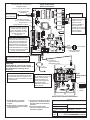
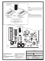
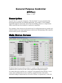
GPC Plus Controller
General Information &
Application Guide
OE331-21-GPC Plus
GPC Plus Controller
.20 Dia.
Typ. of 4
D1
6.2“
CX1
RN1
1
CX3
U3
C21
CX2
U2
U1
CX4
RLY1
U4
V1
D2
TB1
COMM
V2
T
SHLD
RLY2
V3
U5
PAL
RS-485
RLY3
RN3
HH
(1 MEG)
YS101816 REV. 2
U6
D4
LD8
LED1
TUC-5R PLUS
RN2
1
+VREF
C2
V4
D14
R10
D13
JP1
R11
D12
R13
SC1
U13
R15
U12
CX14
C14
R19
C16
U14
CX13
TB4
C15
D19
GND
D16
R22
C19
D18
C18
PJ3
PJ2
EXPANSION
7824CT
R26
R25
CX15
D17
R24
C20
R27
U15
V6
D15
PJ1
PRESSURE
SENSOR
U11
C11
X2
C9
CX12
C13
C12
AOUT2
AIN7
GND C17
CX8
R6
L1
D11
PU7
NE5090NPB3192
0PS
C7
U10
SW1
D9
PU5
0-1
VDC
GND C10
GND
AOUT1
U9
CX10
D10
D7
PU3
AIN5
6.6”
U8
1
2
4
8
16
32
TOKEN
NETWORK
PU1
D6
PU2
D8
PU4
1
ADD
RN5
0-5
VDC
AIN1
AIN2
AIN3
AIN4
R7
ADDRESS
+VDC
RN4
INPUTS
RLY5
V5
C3
R28
X1
PHILIPS
EWDOG
TB2
D5
CX6
5.11V
TEST POINT
RV1
VREF ADJ
COM4-5
RLY4
P1
R1
TB3
R4
R5
C1
LD9
LED2
U7
R1
R2
R3
1
EPROM
RAM
COMM
LD7
PWR
POWER
COMM
7.3”
COM1-3
D3
RCX5
LD6
24VAC
M
The OE331-21 General Purpose Controller Plus (GPC Plus) is used for controlling equipment or processes that cannot be controlled using HVAC controllers.
The Prism computer front end software is
used to interface with the GPC Plus controller functions. The GPC Plus Controller
provides the flexibility to control, schedule
and/or monitor equipment such as unit
heaters, exhaust fans, motorized louvers,
etc.. The GPC Plus has (6) configurable
inputs which will accept signals from
thermistor temperature sensors, 4-20mA
or 0-5VDC transmitters or dry contact
closures. An additional modular input is
provided for connection of an OE271
static pressure sensor. The GPC Plus
has (5) relay outputs for on/off control and
(2) analog outputs. With the addition of
the OE352 2 Slot Expansion Base Board
and (1) OE357 4 Relay Expansion Board,
(4) additional relay outputs are available
providing for a maximum of (9) usable
relay outputs. The GPC Plus also has (5)
separate 2 event per day schedules, each
with its own optimal start functions built
in. In addition the GPC Plus provides
lead/lag start capabilities.
MC34064A
9936
Description
T'STAT
VR1
VR2
6.7”
1.1”
Mounting
The GPC Plus is provided with an integral backplate for mounting inside of a control enclosure. It is recommended that the GPC Plus be mounted in the HVAC unit control enclosure, or in a control enclosure in the
building equipment room. An optional factory control enclosure for the GPC Plus is available.
Technical Data
OE331-21-GPCPLUS
GPC Plus Controller
Power
Power Consumption
Operating Temp
24 Volt AC
8 VA Maximum
10°F to 149°F
90% RH Non-Condensing
Operating Humidity
Weight
Network Connection
Protocol
Communications
Inputs:
Types of Allowed
Inputs
Total Inputs Available
Static Pressure Inputs
Configurable Inputs
Schedules Available
Type III-10kohm sensors
4-20ma sensors
N.O. Binary Contact
N.C. Binary Contact
7
1 (Modular )
6
(5) 2 Event per day
Three Year Warranty
Form: WHP-OE331-21-GPCPlusController-01A.doc
1.5 lb.
RS-485
HSI Open Protocol Token Passing
RS-485 - 9600 Baud
Outputs:
Total Relay Qty. On Board
Total Relay Qty. Available With
Optional Expansion Board
Relay Power Rating
Analog Output Qty.
Analog Output Signal
Optimal Start Schedules
Lead Lag Scheduling
5
9
(2 Amp @ 24 VAC)
2
0-10 VDC
(5) Total - (1) for Each Schedule
(1) Output can be Configured
WattMaster reserves the right to change specifications without notice
Page 1 of 1
C21
U3
CX1
CX2
U1
CX4
RLY1
U4
V1
D2
TB1
COMM
V2
T
SHLD
RLY2
U5
PAL
RS-485
COMM
RAM
RLY3
RN3
HH
(1 MEG)
YS101816 REV. 2
U6
D4
LD8
LED1
TUC-5R PLUS
RN2
1
COM4-5
RLY4
P1
+VREF
TB2
D5
CX6
5.11V
C2
C3
R28
1
INPUTS
ADD
ADDRESS
CX8
C7
R6
D14
X2
CX12
D12
R13
JP1
C9
R11
0-5
VDC
0-1
VDC
D11
PU7
C11
L1
SC1
U11
SW1
R10
U10
D9
PU5
C13
C12
U13
R15
U12
CX14
C14
R19
C16
U14
CX13
D15
U15
TB4
C15
PJ1
D19
GND
EXPANSION
V6
D16
C19
C18
D18
GND
Line Voltage
24VAC
24VAC Transformer
10 VA Mini mum
24VAC
PJ3
PJ2
R26
PRESSURE
SENSOR
R25
CX15
D17
R24
C20
R27
R22
POWER
AOUT2
AIN7
GND C17
TB3
U9
CX10
D13
D8
PU4
NE5090NPB3192
0PS
R7
D7
PU3
D10
PU1
D6
PU2
AIN5
Note: When Using Sensors or
Transducers With 4-20 mA Input
Signal, The Pull-up Resistor For
The Input Being Used Must Be
Removed From The Controller
Board And A 250 Ohm Resistor
Must Be Wired Between The Input
Terminal And The Ground Terminal
On The Controller Board
1
2
4
8
16
32
TOKEN
NETWORK
RN5
GND C10
GND
AOUT1
RN4
U8
+VDC
AIN1
AIN2
AIN3
AIN4
V5
RLY5
EWDOG
RV1
VREF ADJ
V4
X1
Analog Inputs AIN1Thru AIN7
Can Be Used For 10kOhm
Type III Thermistor, 0-5VDC
Signal, 4-20mA Signal Or Dry
Contact Closure Inputs.
As Required.
TEST POINT
PHILIPS
U7
R4
R5
C1
R1
5 Relay Outputs Are
Available On Board For
On/Off Control Of
Equipment. When
Required 4 Additional
Relay Outputs Are
Available By Using The
Optional OE357 4 Relay
Output Expansion
Board. See Below.
R1
R2
R3
1
EPROM
COMM
LD7
PWR
LD9
LED2
Pull-up Resistor- Typical
COM1-3
D3
RCX5
LD6
Mini DIN Connector
For Connection Of Modular
Service Tool
24VAC Power
For Relay Outputs
V3
MC34064A
9936
Connect To
Next Device On
The Local Loop
Local Loop RS-485
9600 Baud
U2
RN1
1
CX3
T To T, R To R, SHLD To SHLD
D1
OE331-21-GPCPLUS
GPC Plus Controller
All Communication Loop Wiring Is
Straight Through
T'STAT
VR1
VR2
Not Used
Splice If Req’d
Connect To
Expansion Board
Base (When Used)
GND
PJ1
PJ2
+24VDC-OUT
GND
LD1
PWR
24VAC-IN
U1
OMRON
74HC04N
G5L-114P-PS
24VDC
CONTACT:
UL 5A250VAC
YS101790
K4
OMRON
PCF8574P
CX3
R14
D3
G5L-114P-PS
24VDC
CONTACT:
UL 5A250VAC
OMRON
LM358N
G5L-114P-PS
24VDC
CONTACT:
UL 5A250VAC
OMRON
C4
VR6
P2
MC
7812CT
OE357
4 Relay Output
Board
U3
C3
VR5
MC
7824CT
U2
U2
VR4
MC
7824CT
CX2
K3 RN1
K3
K4
4RLY IO BD.
P1
CX1
K2
K1
K1
K2
V4
CX2
C5
4 Additional Relay Outputs
Are Available By Using The
OE357 4 Relay Output
Expansion Board. The
OE352 2 Slot Expansion
Base Board Is also
Required To Mount The
OE357 Board.
V1
TB1
Connect Tubing To High Pressure
Port (Bottom Tube) and Route To Static
Pressure Pickup Probe Located In Unit
Discharge. Leave Port Marked “Lo” Open
To Atmosphere
TB1
TB2
S.P.
Transducer
C6
24 VAC Must Be Connected So That All
Ground Wires Remain Common. Failure To
Do So Will Result In Damage To The
Controller
G5L-114P-PS
24VDC
CONTACT:
UL 5A250VAC
Warning:
ULN2803A/
Analog Input AIN6 Can Only Be Used
For Connection Of A Static Pressure
Transducer With Modular Connector
JP2
R10
VR1
2 SLOT MODULAR I/O
YS101780
R6
R5
R4
R12
Jumper
Setting
OE352 2 Slot Expansion Base Board
1.)24 VAC Must Be Connected So
That All Ground Wires Remain
Common.
2.)All Wiring To Be In Accordance With
Local And National Electrical Codes
and Specifications.
JOB NAME
3.)All Communication Wiring To Be 18
Ga. Minimum, 2 Conductor Twisted
Pair With Shield. Belden #82760 Or
Equivalent.
4.)It Is Recommended That All
Controllers Address Switches Are
Set Before Installation.
FILENAME
G-GPC-PlusCNTRL1A.CDR
DATE: 03/08/05
PAGE
1 Of 2
DRAWN BY:
B. Crews
DESCRIPTION:
OE331-21-GPCPLUS
GPC Plus Controller
This Switch Should Be
In The OFF Position
As Shown
ADDRESS
ADD
Note:
The Power To The Controller Must Be Removed
And Reconnected After Changing The Address
Switch Settings In Order For Any Changes To
Take Effect.
S
S
ES
R
D
AD
ES
R
D
AD
1
2
4
8
16
32
TOKEN
NETWORK
D
AD
D
AD
Caution
Disconnect All Communication Loop Wiring
From The Controller Before Removing Power
From The Controller. Reconnect Power And
Then Reconnect Communication Loop Wiring.
Controller
Address Switch
Address Switch Shown Is
Set For Address 1
Address Switch Shown Is
Set For Address 13
The Address For Each Controller
Must Be Unique To The Other Controllers
On The Local Loop.
For Auto-Zone Systems The Address Must Be
Set Between 18 to 30
For All Other Systems The Address Can Be Set
Between 1 to 59
INPUTS
ADD
ADDRESS
+VDC
2
CX10
C7
R6
SW1
D9
PU5
D14
D12
R13
JP1
SC1
C13
U13
R15
U12
CX14
C14
R19
C16
U14
CX13
TB4
C15
D19
GND
D16
R22
V6
D18
C19
24VAC
PJ3
PJ2
PRESSURE
SENSOR
EXPANSION
C18
R25
CX15
D17
R24
C20
POWER
U15
PJ1
R27
D15
R26
C9
R11
X2
C11
0-1
VDC
D11
PU7
GND C10
GND
AOUT1 C12
AOUT2
AIN7
GND C17
L1
CX12
U11
U10
R10
TOKEN
NETWORK
D13
32
R7
D7
PU3
D10
4
8
16
D8
PU4
AIN5
TB3
PU1
D6
PU2
0-5
VDC
AIN1
AIN2
AIN3
AIN4
1
RN5
VR1
VR2
JOB NAME
FILENAME
1.)24 VAC Must Be Connected So
That All Ground Wires Remain
Common.
2.)All Wiring To Be In Accordance With
Local And National Electrical Codes
and Specifications.
3.)All Communication Wiring To Be 18
Ga. Minimum, 2 Conductor Twisted
Pair With Shield. Belden #82760 Or
Equivalent.
4.)It Is Recommended That All
Controllers Address Switches Are
Set Before Installation.
G-GPC-PlusCNTRL1A.CDR
DATE: 03/08/05
PAGE
2 Of 2
DRAWN BY:
B. Crews
DESCRIPTION:
OE331-21-GPCPLUS
GPC Plus Controller
General Purpose Controller
(GPCPlus )
January 31, 2005
Description
The GPCPlus is a controller designed to “fill in the blanks” between standard off the
shelf programs and minor non-standard applications. An example of a non-standard
application might be exhaust fan control, based on building pressure or a simple boiler
enable controller based on schedules or outdoor air temperature.
The remainder of this document will describe the I/O configurations that are possible and
will also include a few sample applications to aid the user in determining if this controller
will meet their specific requirements.
Main Status Screen
The Main Status Screen provides real-time live updates of the current operating
conditions and is used to access the various setpoint and configuration options.
No control takes place until the user “configures” the operation of the GPCPlus. Access
to the various configuration screens is made by a simple left mouse-click on the
individual reading or output status box for each I/O Point. As a general rule, a left click
1
accesses the configuration for the selected item and a right click accesses the force mode
options if any are available.
Analog Inputs
Relays
Analog Outputs
2
Week Schedules & Holidays
3
Analog Input
Configurations
The first five analog inputs and input #7 can be configured in several different ways.
Input #6 can be used for Static Pressure and accepts the standard pressure sensor with the
phone jack connector, available from WattMaster Controls.
The following configurations are available:
1.
2.
3.
4.
5.
6.
7.
Thermister Type III Temperature Sensors (Scaled for Fahrenheit)
Thermister Type III Temperature Sensors (Scaled for Celsius)
4 – 20ma User Scaled
0 – 5 vdc User Scaled
Wall Sensor Slide Offset
Binary Contact Closure
Read Global Analog Broadcast from another Controller
4
8. Read Global Binary Broadcast from another Controller
9. Sensor #6 can be assigned to read Static Pressure
Each input is separately configured so combinations of any type of input on the same
controller are possible.
All readings can be overridden to specific values for test purposes. All thermister sensors
can also be calibrated by entering positive or negative offsets to be applied to the current
readings. All 4 – 20ma readings can be calibrated if the user has the exact current or
resistance values available for entering in the calibration fields.
Right-Click on the desired analog input reading to access the pop-up menu shown above
and then select the desired function. If you are calibrating or overriding the reading, the
following window will pop-up. Enter the desired calibration offset or specific reading
you wish to force the input to and press the Enter key. The window will automatically
close and send the command to the controller. If you select the Clear Sensor Override
option, a window will not appear but the clear command will be sent to the controller.
- OR -
5
Any or all readings can also be “broadcast” to other controllers on the communications
loop. For example, the Outdoor Air Temperature is broadcast on channel #2 by any unit
that happens to have the sensor attached. If none of the standard package units have the
outdoor air sensor attached, you could attach it to the GPCPlus and select it for broadcast
on channel #2. All other controllers would “hear” the broadcast and use it in their normal
operations. On the other hand, if you are measuring something like return air humidity,
do NOT select channel #2 to broadcast it on, since all the package unit controls are
expecting the outdoor air temperature. If no package controllers exist on your system
then you are free to use any available global channel for broadcast. There are 32 possible
global analog channels and 16 possible global binary channels.
Select global analogs to broadcast readings and global binary channels to broadcast
contact closure (on/off) information.
If you select one of the unassigned channels for broadcast, it is assumed that you have
other GPCPlus units installed that expect to receive information on those channels since
the standard package code does not listen for broadcasts on unassigned channels.
CAUTION: If you elect to broadcast a reading from the GPCPlus to all
other controllers on your installation, be sure to check the
HELP screen to identify which Global Channels have
already been assigned.
Each input also provides high and low alarm limits if the user requires out of range
values to notify service personnel. The alarm limits can be widened at night and they can
also be forced to be out of limits for a user defined amount of time before an alarm
occurs. This prevents false alarms if the reading temporarily exceeds the limit but then
recovers and stays within the limits the remainder of the time.
All readings are user scalable. That means you can display values with ± 1, ± 0.1, ± 0.1±
0.01 or higher resolutions. Just keep in mind that the maximum value that can be sent
from the controller is ±30,000 so if you have scaled your reading to ± 0.001 then the
maximum value you can send is ± 30 with the 3 additional decimal values (30.000).
6
Each input can also have an appendix selected to display with the reading to make them
more user friendly. The possible appendix values are:
•
•
•
•
•
•
•
•
•
•
•
•
•
(None)
RH%
%
°F
°C
PPM
PSI
“WG
“
Ft.
RPM
VDC
BTU
No Appendix Required
Relative Humidity
Percentage
Degrees Fahrenheit
Degrees Celsius
Parts Per Million
Pounds Per Square Inch
Inches of Water Gauge
Inches
Feet
Revolutions Per Minute
Volts Direct Current
British Thermal Units
On inputs selected for Binary Input Contact Closure, the user can select Normally Open
or Normally Closed Contacts.
7
Wall Sensor Slide Offset
If you have configured a specific input to be connected to one of WattMasters’ standard
OE212 or OE213 Flush Mount Wall Sensors which contain the optional slide offset, be
sure to enter a value for “Maximum Slide Offset Effect”. This tells the controller how
much effect to have on the selected setpoints when the slide is fully deflected up or down.
When the slide is in the “center” position, it has no effect on the current setpoints.
Note:
There are separate outputs on the Flush Mount Wall Sensors
for measuring the room temperature and reading the slide
offset. Be sure to configure the correct input for the slide offset
and do not use the temperature signal coming from the wall
sensor for this option.
The slide offset is normally used by one or more relay outputs, configured to “look” at
this value and include its effect on their normal setpoints.
As you can see on the sample screen, Relay #4 is set to activate if the LoadTemp rises
above 72.0°F. It is also monitoring the Sensor Slide Adjust input on Analog Input #5. If
the slide is pushed up, the Hi Limit Setpoint will rise to 74.0°F and the Lo Limit Setpoint
8
to 72.0°F. If the slide is pushed down, the Hi Limit Setpoint will drop to 70.0°F and the
Lo Limit Setpoint to 68.0°F.
Push-Button Override
If you have configured a specific input to be connected to one of WattMasters’ standard
OE211 or OE213 Flush Mount Wall Sensors which contain the optional push-button
override, be sure to enter a value for “Push-Button Override Duration”. To use this option
you must select which schedule will be affected by the override event. (See screen
below).
Optimal Start Temperatures
You can configure any of the first five inputs to be used as the Optimal Start “Target
Temperature” sensor. As with the override option, you must select which schedule will
use this temperature for its optimal start calculations.
You also must enter a Cooling and a Heating Target setpoint for this feature to work
correctly.
9
Analog Input #6
This analog input is reserved for Duct Static Pressure. This value can then be used to
monitor the duct static or to actually control the duct static using an analog output and
driving either inlet vanes or a VFD controller. It is not recommended that you attempt to
use relays to control the duct static pressure, although this reading can be selected as a
control source on the relay configuration screen.
CAUTION: If you select two relays to control duct static, WattMaster
Controls cannot assume any liability for equipment
damage caused by over-pressurization of the duct work!
If you require a Duct Static Pressure Sensor, you must use an OE271 sensor provided by
WattMaster Controls for proper sensor readings. No other sensors are currently supported
for this input.
All setpoints related to duct static control pressures and alarm points are programmed on
this screen which activates when you left-click on the pressure reading box.
10
Relay Output
Configuration
Control Methods
Each individual output relay can be configured separately for one of the following
methods of control listed below.
0
1
2
3
4
5
6
7
=
=
=
=
=
=
=
=
Not Configured
On Above High Limit Setpoint and Off Below Low Limit Setpoint
On Above High Limit Setpoint and On Below Low Limit Setpoint
Off Above High Limit Setpoint and On Below Low Limit Setpoint
Off Above High Limit Setpoint and Off Below Low Limit Setpoint
On with Contact Closure on Selected Input
Off with Contact Closure on Selected Input
Follow Schedule Only
11
8
9
10
11
=
=
=
=
Follow Global Binary Only
Ventilation Control
Lead Relay for Lead/Lag Control
Lag Relay for Lead/Lag Control
Control/Reset Sources
The Control Source is also selectable. This control source can be an analog value or an
on/off contact closure. The list of possible sources is shown below.
0 = Not Configured
1 = Sensor Input #1
2 = Sensor Input #2
3 = Sensor Input #3
4 = Sensor Input #4
5 = Sensor Input #5
6 = Sensor Input #7
7 = Static Pressure
8 = Outdoor Air
9 = Calculated Wetbulb Temperature (Requires a sensor configured for Humidity)
The Logical AND Source and the Logical OR Source also use the same list of available
sources for their control also.
Enabling Relay
Interaction between relays is possible via an Enabling Relay feature. This allows the user
to prevent a specific relay from activating until one of the other relays has had a chance
to activate (See Sample Configurations Section). This can include such things as waiting
for a fan to start before operating a heating or cooling stage.
Delay & Run Times
The relay can also be forced to remain on for a minimum amount of time or remain off
for a minimum amount of time to prevent rapid cycling on and off under borderline
operating conditions. A Starting Delay Period is also available so that a relay must also
wait this amount of time, once it is enabled to activate before the relay output is actually
energized.
Reset Source Limits
The Reset Source Limits are only required if you need the controlling setpoint to vary
between the Hi Limit Setpoint and Lo Limit Setpoint based on some other condition
12
such as outdoor air temperature. If no reset is required, simply enter the same values for
the Control Source Hi and Lo Limit Setpoints. No Reset Source is required.
If you do need the main Control Source Setpoint to reset, this is the range over which
the Reset Source must change to cause the controlling setpoint to reset from the Lo Limit
to the Hi Limit values you entered. For example: you want to reset the enable/disable
point for a boiler enable signal based on the changing outdoor air temperature. You
would enter the Minimum outdoor air temperature that would cause the Hi Limit
Setpoint to be calculated and the Maximum outdoor air temperature that would cause the
Lo Limit Setpoint to be calculated.
Controlling Setpoint Deadband
You should always enter a small deadband to prevent the relay from cycling on and off
continuously due to a control source reading that is toggling right around the current
setpoint. The deadband you enter is added to both sides of the setpoint to create an area
where the relay does not stage on or off. For example: if your setpoint was 72°F and the
deadband was set for 0.5°F, the relay can change state when the temperature rises above
72.5°F or drops below 71.5°F. If you do not need unoccupied setback control, you must
leave this setpoint = 0.0°F and use the High and Low setpoints to create a deadband.
Controlling Schedule
You can select one of the Internal Schedules to set the occupied or unoccupied mode of
operation for the selected relay. If the relay does not require a schedule to be part of its
control strategy, leave the selection at “None Selected”.
AND/OR Conditional Tests
If more than one criterion is required to make a decision, there are two other options
available to aid in the decision process. An AND condition and an OR condition. If you
don’t need additional tests, simply select the Not Configured option under the Control
Method for each of these sources.
If you need two events to be true before the output can activate, use the AND Control
Method and select a Logical AND Source.
If you want either the main Control Method OR an Alternate Control Method to activate
the output, use the OR Control Method and select a Logical OR Source.
You can combine all three options to create a condition where two events must be true or
a third separate event must be true to activate the output.
13
Run Time Alarm
If the selected relay output is controlling a device that needs periodic maintenance, you
can enter a Run Time Alarm Delay period that, once exceeded, generates an alarm
condition that will notify the user when it occurs. If you need to protect the equipment
you can select the Disable Relay box and the relay will de-activate once this run time has
been exceeded.
Relay Output Type
Some control methods require the relay contacts to be closed when the output is
activated, others require the contacts to be open. You can select which method of control
to use with this option.
Global Binary Channel
If this output was configured to follow a global binary broadcast, enter which channel (1
- 16) the relay should follow. The output will be active when the binary value is “1” and
will de-activate when the value is “0”.
Lead/Lag Control
If you have configured this relay as the Lead relay in a Lead/Lag control scheme then
you will also need to set the Changeover Interval and the Proof Failure Timeout Delay
shown on the right hand side of the relay configuration screen.
The Changeover Delay is used to toggle the Lag output into the Lead once the runtime
hours of the Lead output exceed this amount of time on the Lag output.
The Proof Failure Time Delay is the amount of time given for the “Proof of Flow” input
to become active once the Lead or Lag output is energized. If this proof is not made
within the specified amount of time, the controller switches to the Lag output in an
attempt to get the controller running and then sets an alarm to flag the user that
something is wrong.
Hi/Lo Limit Setpoints
All On/Off control methods require setpoints to be entered for control purposes. The
relay state changes based on the control method selected and the current reading versus
the Hi Limit Setpoint or Lo Limit Setpoint. If you have selected the On Above and
Off Below method, then the relay would be active when the reading exceeds the Hi Limit
Setpoint and it would not be active below the Lo Limit Setpoint. In either case, the user
defined Deadband would also need to be satisfied before the actual relay change of state
occurs.
14
Ventilation Control
You can configure an output to operate in a ventilation control mode. This means that the
output is active for the Vent Mode ON Time and then cycles off for the Vent Mode OFF
Time. If the output is not enabled by a schedule or another relay, it will continue to cycle
indefinitely at this On/Off rate.
15
Analog Output
Configuration
Two Proportional Outputs ( 0 - 10 VDC ) are available to the user. This output operates
using standard floating point control or a modified Proportional/Derivative control as
configured by the user. The controlling setpoint can be reset by any other sensor reading
or the outdoor air temperature and the output voltage range can be limited by the user to
some range other than the standard 0 - 10 VDC.
Possible Control Modes
0 = Not Configured
1 = Direct Acting Floating Point
2 = Reverse Acting Floating Point
3 = Direct Acting PID
4 = Reverse Acting PID
5 = Relief Pressure Control
6 = Duct Static Pressure Control
16
7 = Proportional Reset Signal
8 = Economizer Control
9 = Lead/Lag Pump VFD Control
Possible Control Sources
0 = Not Configured
1 = Sensor Input #1
2 = Sensor Input #2
3 = Sensor Input #3
4 = Sensor Input #4
5 = Sensor Input #5
6 = Sensor Input #7
7 = Static Pressure
8 = Outdoor Air
9 = Calculated Wetbulb Temperature (Requires a sensor configured for Humidity)
Floating Point Control
If you select Direct or Reverse Acting Floating Point Control, this means that the output
voltage on Direct Acting increases as the control signal goes above the setpoint and drops
as the signal falls below the setpoint. In Reverse Acting mode, the voltage drops as the
control signal goes above setpoint and falls when the control signal goes below setpoint.
This type of control works best on very slow changing applications where the amount of
time it would take to drive full on or full off is not critical. For faster response, the PID
Control method is recommended.
A deadband setpoint is available if you wish to set the Hi/Lo setpoints the same and only
change the voltage if the control signal is further from setpoint than the deadband
amount.
PID Control
The PID control is a WattMaster modified version of Proportional and Derivative Rate of
Change Control. The only user setpoints required are the Calculation Interval which can
speed up or slow down the control changes and whether or not to use the Rate of Change
feature. Also, the minimum and maximum output range can be set to something other
than full on or full off.
This Rate of Change control is the preferred method for most valve or actuator control
situations. It “self-adapts” to changing load conditions and “remembers” where it was the
last time it was de-activated and attempts to restart the process at that known point
whenever it is called back into action.
17
Economizer Control
If you have configured the GPCPlus as a very simple Air Handling Unit, it has the ability
to control the outside air dampers in a true first stage economizer cooling mode. This
mode requires a Minimum Ventilation position that it maintains whenever the
economizer is not enabled for cooling. It also needs to know which relay has been
configured as the first compressor stage. Use the Outdoor Air Enable limits to set when
the free cooling mode can be used in conjunction with scheduling and temperature
demands.
Alternate Override
There are situations where we want normal control to be suspended temporarily
whenever an unusual situation occurs. For example: we are using the economizer control
method and we have installed a CO² sensor on this controller to use for Indoor Air
Quality. If the CO² reading exceeds a specified level, this Alternate Override can take
charge and move the output signal to a pre-designated level to bring the IAQ back under
control.
Proportional Reset Signal
As the Reset Source goes from its Maximum Reset Source to its Minimum Reset
Source the Controlling Setpoint goes from its Minimum Reset Setpoint limit to its
Maximum Reset Setpoint limit.
Since the reset limits can be set to any desired value, the user can initiate a reverse acting
proportional reset or a direct acting proportional reset of the setpoint simply by crossing
the min and max values if direct acting is required.
Direct Acting = As Temperature Rises the Setpoint Drops
Reverse Acting = As Temperature Rises the Setpoint Rises
An example of using Proportional Reset would be for Boiler Control. As the outside air
temperature rises, we would like the boiler output temperature to drop. We would use the
outside air temperature as the control source and set the Max Setpoint and Min Setpoint
to the range we want to vary the voltage from 0 to 10.0 vdc. If we set the Max Setpoint to
50° and the Min Setpoint to 60° then as the outside air rose from 50° to 60°, the output
signal would drop from 10.0 vdc @ 50° to 0.0 vdc @ 60°. This is because we made the
output Reverse Acting by setting the Max Setpoint lower than the Min Setpoint.
18
Lead/Lag Pump VFD Control
If you are using the GPCPlus as a Lead/Lag controller and you need to maintain loop
pressure or some other analog signal, configure an output for this method of control.
Then all you need to do is enter the control setpoint on the Lead Relay configuration
screen and this output will attempt to modulate and maintain that level of control while
the Lead/Lag control is active.
19
Sample Configurations
Sample #1
The user would like to control 4 boilers. Each boiler is controlled from the same Water
Temperature sensor but at a different temperature reading. Once a boiler is activated it
must remain on at least 5 minutes and if a boiler is de-activated it must remain off at least
10 minutes. Additionally, the boilers are locked out when the Outdoor Air Temperature is
above 65°F.
Analog Input #1 Configured as Thermister Type III Sensor
Note that some Hi and Lo alarm limits were set and that the reading is in degrees
Fahrenheit.
20
Analog Input #2 Configured as Outdoor Air Thermister Sensor
Notice that we set this reading to broadcast on Global Analog Channel #2. That is
because the Outside Air is normally read by one controller on a job and the remaining
controllers look at Global Analog #2 for this value, including the GPC Plus. Even if this
is the only controller on the job, you must set it to broadcast the outside air so the GPC
Plus can “see” what the OA Temperature is.
Analog Input #3 Configured as Not Configured
Analog Input #4 Configured as Not Configured
Analog Input #5 Configured as Not Configured
Analog Input #6 Duct Static Pressure Sensor is not Required
Analog Input #7 Configured as Not Configured
21
Relay Output #1 Programming ( Used for Outdoor Air Enable / Disable )
NOTE: Nothing is physically connected to Relay #1. Its only use is to
enable or disable the other relays.
22
Relay Output #2 Programming ( Used for Boiler #1 )
As you can see, the first boiler stage is enabled to operate if the water temperature is
below 175°F and will remain on until it rises to 190°F. This first stage can only operate if
the outdoor air enabling relay #1 is active. Once activated, the boiler must remain on for
5 minutes (300 seconds) and once de-activated it must remain off for 10 minutes (600
seconds).
Since we are not resetting the operating setpoint, the Reset Source has been left as “None
Selected”. We also don’t require a “Logical AND” or “Logical OR” condition so they
have been left Not Configured. There is no need to enable this output from a schedule
since it uses an Enabling Relay (OAT Enable) which does require the schedule before it
can activate based on the Outside Air Temperature.
23
Relay Output #3 Programming ( Used for Boiler #2 )
The second boiler stage is enabled to operate if the water temperature is below 170°F and
will remain on until it rises to 180°F. The second stage can only operate if the first boiler
stage relay #2 has been active for at least 5 minutes. Once activated, this stage must
remain on for 5 minutes and once de-activated it must remain off for 10 minutes.
24
Relay Output #4 Programming ( Used for Boiler #3 )
The third boiler stage is enabled to operate if the water temperature is below 160°F and
will remain on until it rises to 175°F. The third stage can only operate if the second boiler
stage relay #3 has been active for at least 5 minutes. Once activated, this stage must
remain on for 5 minutes and once de-activated it must remain off for 10 minutes.
25
Relay Output #5 Programming ( Used for Boiler #4 )
The fourth boiler stage is enabled to operate if the water temperature is below 150°F and
will remain on until it rises to 170°F. The fourth stage can only operate if the third boiler
stage relay #4 has been active for at least 5 minutes. Once activated, this stage must
remain on for 5 minutes and once de-activated it must remain off for 10 minutes.
The Starting Delay Period that was set for stages 2 to 4 prevent all four boiler stages
from activating at the same time as soon as they are enabled to begin operation. Each
stage must run for 5 minutes before the next stage can be activated.
Analog Output Programming
Control Source
Not Configured
Since no analog output control is required, simply leave the Control Source set to Not
Configured on both outputs and no analog output control will take place.
26
Operation
Relay #1 enables the boilers to operate if the outdoor air temperature is below the low
setpoint and the schedule is occupied. Each boiler is enabled to operate if the previous
boiler is currently active and has been on for at least 5 minutes. All four boilers monitor
the same analog input sensor for the Water Temperature reading. The #1 Enable Relay
can monitor a global broadcast from another controller on the RS-485 communications
loop for the outdoor air temperature but, in this case, we are reading the Outdoor Air
Temperature on Analog Input #2. Notice on the Analog Output #2 configuration screen
that it was also configured to broadcast on Global Analog Channel #2. That is because
the GPC Plus doesn’t have any other way of knowing that it is the one reading the
outdoor air temperature.
The voltage output is not used so no control source is selected, and no other related
setpoints require modification.
Shown below is a sample Status Screen for this sample application. Notice that the
boilers are not enabled even though the schedule is active because the outdoor air
temperature is too high.
27
This next sample screen shows that the outdoor air temperature has dropped enough to
enable the boilers to operate. The system has been running long enough to satisfy all 4
Boilers 5 Minute Starting delay so they are all active at this point. It took roughly 20
minutes to get all 5 relays active since each has a 5 minute Staging Delay time period.
Keep in mind that although Relay #1 (OAT Enable) is active, nothing is connected to the
output because its only function is to provide an outdoor air enable signal for the boiler
staging.
28
Sample #2
The user would like to use the GPC Plus as a Lead/Lag Air Handling Unit Controller.
The installation is located in a critical area that does not tolerate the space temperature
going out of control. The method chosen was to install a backup AHU that would take
over in case of failure on the Lead AHU. Also, since the units are identical, the owner
wanted to equalize the run-times to lengthen the time between routine maintenance
service calls. The easiest method for handling this was to use two, standard, off the shelf
AHU controllers and a GPC Plus controller that would enable the appropriate AHU
based on changeover and failure mode conditions. The GPC Plus would use contact
closures to the Forced Occupied inputs of the AHU controllers to activate and de-activate
the units. A failure mode would be indicated by the failure of the Supply Air
Temperature to drop below or stay below a 60°F setpoint. Any temperature excursions
above 60°F for more than one minute would indicate a failure had occurred and that the
Lag AHU should be activated and an Alarm generated to let building maintenance know
there was a problem.
Analog Input #1 Configured as Thermister Type III Sensor to measure Supply Air
As you can see, this input does not use a schedule for Night Setbacks since the unit will
run 24 hours a day. It does however, monitor the Supply Air Temperature for values that
are out of limits for more than a half hour and generates an alarm condition. This is a fall
29
back alarm condition because the Lead/Lag control should have already generated an
alarm if something was wrong and the standby AHU was called into action. Be sure to
check the Alarming Enabled box if you want this alarm to be reported back to the PRISM
screen or to a Remote Pager.
Analog Input #2 - #7 The remaining inputs are not required for this program.
Relay Output #1 Programming ( Used for Lead AHU Enable Signal )
This relay was chosen to be the Lead control output and was connected to AHU #1.
Either AHU could have been selected as AHU #1, this was an arbitrary decision. The
Supply Air was selected as the Control Source and the Proof Setpoint was set to 60.0°F.
The AHU’s will change the Lead every 24 Hours and if the Supply Air rises above 60°
for more than 60 seconds, it will be considered to be in failure mode and the Lag AHU
will be activated. Also, an alarm will be generated so that an immediate service call can
be made to determine the cause of failure. If both units should happen to fail, there is no
further redundant capabilities and service personnel will need to correct the problems and
then Reset the control from the Alarm Indicator Screen (shown later in this section).
30
Relay Output #2 Programming ( Used for Lag AHU Enable Signal )
There are no other settings required for the Lag Controller. All control logic from the
Lead relay is used in the decision making process.
Analog Outputs (No Analog Output Control is Required for this Program)
31
Main Status Screen ( Normal Operations )
As you can see on the Status Screen shown above, the unit is operating normally and the
Supply Temperature is at 51.9°F, well within the normal operating range and no alarms
are currently active.
There are no schedules active since this unit is required to operate 24 hours a day. The
relay outputs will operate their control modes around the clock if no schedule was
selected on the relay configuration screen.
32
Main Status Screen ( Failure Mode )
The Supply Air rose to 61.9°F and the Lag AHU was activated.
The alarm screen indicates the Lead AHU failure.
33
Both AHU’s are now off because the Lag AHU failed to lower the Supply Air below
60°F.
34
The alarm screen indicates both outputs failed to control the Supply Temperature. At this
point, the service personnel will need to correct the problem and then select the Reset
Pump/Fan button to restart the GPC Plus Lead/Lag control sequence.
Although the button and alarm indicators show Lead Pump / Fan indicators, the outputs
are not limited to those types of control. You just need to understand that the Lead Pump
/ Fan controls AHU #1 in this sample and Standby Pump / Fan controls AHU #2.
35
Form: WHP-GPCPlus-APP-01A Printed in the USA
March 2005
All rights reserved
Copyright 2005
WattMaster Controls Inc. • 8500 NW River Park Drive • Parkville MO • 64152
Phone (816) 505-1100
www.wattmaster.com
Fax (816) 505-1101