1
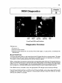
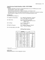
HP 9000 Series 500 Computers
9050 CE Handbook
Reorder Number
09050-90035
Requires Binder No. 9282-0683
Printed in U.S.A. 5/85
Flidl
':1:.
HEWLETT
PACKARD
-""-n .. ,, ,..,.....- .,.. ....
I~' I '
..... I-i _ _ "., h -
'-'I
~
,.".~ ...... ,. .... Jfr
'-.#' ..
,..
•
••
11;,
"!'"
..... I -
~ ._t{I'11 __ ."t-r>.~
for the HP 9000 Series 500
Manual Reorder No. 09050-90035
Note
This handbook is only for the use of HP Qualified Service Personnel.
© Copyright 1985, Hewlett·Packard Company.
This document contains proprietary information which is protected by copyright. All rights are reserved. No part of this
document may be photocopied, reproduced or translated to another language without the prior written consent of
Hewlett·Packard Company. The information contained in this document is subject to change without notice.
Restricted Rights legend
Use, duplication, or disclosure by the Govemment is subject to restrictions as set forth in paragraph (b)(3)(8) of the
Rights in Technical Data and Software clause in DAR 7·104.9(a).
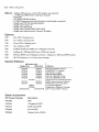
Product Information
Environmental/Installation/PM
Configuration
Troubleshooting
Diagnostics
Adjustments
Peripherals
Replaceable Parts
I
I
I
I
I
I
I
Ii
Diagrams
I
Reference
II
Service Notes
II
ii
Printing History
New editions of this manual will incorporate all material updated since the previous edition. Update
packages may be issued between editions and contain replacement and additional pages to be
merged into the manual by the user. Each updated page will be indicated by a revision date at the
bottom of the page. A vertical bar in the margin indicates the changes on each page. Note that pages
which are rearranged due to changes on a previous page are not considered revised.
The manual printing date and part number indicate its current edition. The printing date changes
when a new edition is printed. (Minor corrections and updates which are incorporated at reprint do
not cause the date to change. ) The manual part number changes when extensive technical changes
are incorporated.
May 1985 ... Edition 1. This manual replaces part no. 09050-90039.
Warranty Statement
Hewlett-Packard products are warranted against defects In materials and workmanship. For Hewlett-Packard computer system products sold in the US A and Canada. this warranty applies for ninety (90) days from the date of shipment' HewlettPackard will. at ItS option, repair or replace equipment which proves to be defective dUring the warranty period This warranty
Includes labor. parts. and surface travel costs, if any Equipment returned to Hewlett-Packard for repair must be shipped
freight prepaid Repairs necessitated by misuse of t~e equipment or by hardware software or Interfacing not provided by
Hewlett-Packard are not covered by this warranty
HP warrants that its software and firmware designated by HP for use with a CPU will execute its programming instructions
when properly installed on that CPU HP does not warrant that the operation of the CPU. software. or firmware Will be uninter·
rupted or error free
NO OTHER WARRANTY IS EXPRESSED OR IMPLIED. INCLUDING BUT NOT LIMITED TO. THE IMPLIED WARRANTY OF
MERCHANTABILITY AND FITNESS FOR A PARTICULAR PURPOSE HEWLETT-PACKARD SHALL NOT BE LIABLE FOR
CONSEQUENTIAL DAMAGES
• For other couf1tnes cor>tac! your local Sales and Support Office to deenT'lre warrar:~y terfT'S
1-1
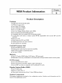
9050 Product Infonnation
.
~__________________
~II~al~~1
_
Product Description
Features
•
•
•
•
•
•
•
•
•
32 Bit CPU with 32 bit data paths.
12 Slot processor stack.
Up to three CPU boards.
Up to 10M bytes of RAM.
One or two lOP boards.
Up to four Display Station Buffer cards (DSB).
Error correcting and self healing memory.
Compatible with 4.0 and later HP-UX operating system .
7 C-IIO Slots with built in medium speed HP-IB. Expandable with second lOP and 110
expander.
•
•
•
•
Real time clock.
Nicad battery for RTC and NVM.
Variable speed fans for noise reduction.
LED indicators for self-tests.
Central Processor Unit
• Improved NMOS III CPU.
• Hoating point math chips for improved capability.
• Math chips invisible to operating system.
• Can have 3 CPUs.
Memory
• Up to 10 Cards of RAM (either 512K byte or 1M byte cards)
• RAM cards can be any combination in the same stack (lM byte boards must be used in pairs).
I/O Processor
• one or two lOPs can be used.
• Seven channel 1/0 card slots. (Select codes 0 Through 6.)
• Second lOP can drive an expander with 8 additional 110 cards.
Display Station Buffer (DSB)
• Up to 4 DSB cards.
• Must be in slots 4 thru 7.
• Other stack cards use slots 4 thru 7 when DSBs are absent.
System Components
The system components are listed in the configuration section. Interface card information can be
found in the peripherals section.
1-2 9050 Product Information
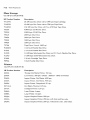
System Software
A list of the system software is in the reference section.
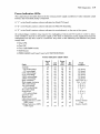
Tools List
HP Part Number
Description
9300-0794
Antistatic Kit
09855-67004
Power Supply Discharge Tool
8710-0899
# 1 Pozidriv Screwdriver
8710-0900
#2 Pozidriv Screwdriver
8730-0001
Flat Blade Screwdriver
8710-0585
Ie Extractor
8720-0007
112 inch Nut Driver
8720-0005
3/8 inch Nut Driver
Related Documentation
Related Documents are listed in the reference section.
Safety
LETHAL VOLTAGES ARE PRESENT INSIDE THE HP 9050.
OBSERVE ALL WARNINGS ON THE COMPUTER AND IN THE
DOCUMENTATION. SWITCH OFF POWER AND UNPLUG POWER
CORD FROM AC OUTLET BEFORE REMOVING ANY ASSEMBLIES.
ENSURE THERE IS CONTINUITY BETWEEN GROUND AND METAL CHASSIS AFTER MAKING ANY PRIMARY WIRING CHANGES.
"l-';I¢"UN
DO NOT REMOVE POWER SUPPLY FROM THE COMPUTER
WITHOUT DISCHARGING THE POWER SUPPLY CAPACITORS
WITH THE POWER SUPPLY DISCHARGE TOOL. IF A TOOL IS
NOT AVAILABLE, WAIT 15 MINUTES FOR THE CAPACITORS TO
DISCHARGE.
2-1
I
9050 EnvironmentalllnstallationIPM
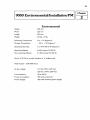
Environmental
Height
234mm
Width
325mm
Length
530mm
Weight
20 Kg ±5 Kg
Operating Temperature
o to
Storage Temperature
+ 55 Degrees C.
- 40 to + 75 Degrees C.
Operating Humidity
5 to 95% RH at 40 Degrees C.
Operating Altitude
4600 metres (15 000 ftl
Non-operating Altitude
15 300 metres (50 000 ftl
Shock of 30 Gs for a pulse duration of 11 milliseconds.
Heat Output - 2100 BTU/hour
Ac line voltage
110 Vac (90 to 125 Vacl
220 Vac (198 to 250 Vacl
Line frequency
48 to 66 Hz
Power consumption
580 watts maximum
Power Supply
400 watt switching power supply
I~
~
2-2 9050 Environmental/Installation/PM
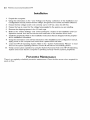
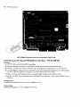
Installation
1. Unpack the computer.
2. Using the information in the "Line Voltage and Fusing" subsection of the Installation and
Configuration manual, ensure the line voltage, and ground, are correct and within tolerance.
3. Ensure the line voltage switch is set correctly: up for 110 Vac; down for 220 Vac.
4. Ensure the fuse is correct for the voltage being applied to the system you are installing.
5. Remove the shipping spacers in the 110 card cage.
6. Refer to the "Switch Settings" and "Interconnections" sections in the Installation and Configuration manual, then set the switches and install each of the interface driver cards.
7. Install the peripherals. Refer to the installation instructions that are shipped with the peripherals for installation information.
8. Using the information in the self-test subsection of the Installation and Configuration manual,
apply power to the computer and ensure that it passes all the self tests.
9. Load the HP-UX Operating System. Refer to the "System Administrator Manual" to load
and run the system operating software. Ensure all self-tests are successfully passed.
10. Verify correct system operation by using the System Functional Test in the HP-UX Operating
System and ensure that the computer is operating correctly with the systems peripherals.
Preventive Maintenance
There is no regularly scheduled preventive maintenance. Clean the filter screen when required for
good air flow.
3-1
9050 Configuration
.
~________________
~llcha3~rl
_
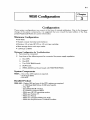
Configuration
These system configurations are current at the time of manual publication. Due to the frequent
change of the system components, it is suggested that you consult the latest edition of the Supported Peripherals Matrix for current information.
Minimum Configuration
•
•
•
•
HP9050.
System console (terminal and interface).
Revision 4.0 or later HP-UX on 114 inch tape cartridge.
Mass storage device with tape reader.
• 1.5M byte of RAM.
Minimum Configuration for Troubleshooting
1. Fans must be connected.
2. Any three of the following must be connected for power supply regulation.
a.
b.
c.
d.
e.
One Cpu.
One lOP.
Two 512K RAM boards.
SCM board.
09855-66525 load board (used with 9020/9030/9040).
System Components
9050A - One of the CPU options is required.
- 512K byte RAM.
-One lOP.
Bundled Product
9050 AM - Option 022 and one of the CPU options are required.
- 1 112M byte RAM (three 512K byte boards).
-One lOP.
- 27110A/B HP-IB interface.
- 27130AlB 8-Channel MUX.
- Multi-user HP-UX operating system.
- Multi-user Fortran 77.
- Multi-user Pascal.
- Multi-user Graphics/9000 DGLIAGP.
- Multi-user Asynchronous Terminal Emulator.
3-2
9050 Configuration
9050 AT - Option 022 and one of the CPU options are required.
- 1 112M byte RAM (three 512K byte boards).
-One lOP.
- 27110AlB HP-IB interface.
- 27128A Asynchronous Serial Interface (with female connector).
- Single user HP-UX operating system.
- Single user Fortran 77.
- Single user HP Pascal.
- Single user Graphics/9000 DGLIAGP.
- Single user Asynchronous Terminal Emulator.
Options
500
One CPU, floating point.
600
Two CPUs, floating point.
700
Three CPUs, floating point.
249
One additional lOP.
246
Additional 2M byte RAM (two IMegabyte boards).
247
Additional 112M byte RAM (one 512K byte board).
248
4M byte RAM (four IMegabyte boards - Replaces 112M byte RAM boards).
022
HP-UX Software on 114 inch tape cartridge.
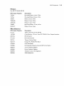
System Software
HP Product No.
Single-User
Multi-User
97070A
97071A
97072A
97073A
97074A
97075A
97080A
97081A
97082A
97083A
97084A
97085A
97076A
97077A
98163A
97087A
98183A
2285A
97086A
50953A1M/R
50954A1M1R
Stack Accessories
HP Product Number
Description
97043B
CPU
97046A
1 Megabyte RAM
97047A
512K byte RAM
97049A
Second lOP
98288A
Display Station Buffer
Software
HP-UX Operating System
FORTRAN 77 Compiler
HP Pascal Compiler
IMAGE-9000 DBMS
HP-UX GRAPHICS DGL
HP-UX GRAPHICS AGP
Asynchronous Terminal Emulator
RJE Communications Software
HPSPICE Circuit Simulation
Local Area Network
Applications Migration Package
HP 27125 LANIC Software
9050 Configuration
Interface Cards
HP Product Number
Description
BuiltIn
Internal HP-IB Interface
2285A
LAN Local Area Network Interface. Use HP 27110A - HP-IB.
27110NB
HP-IB Interface
27112A
GPIO General Purpose Interface
27122A
RJE Interface
27123A
SRM Interface
27125A
LANIC Interface
27128A
ASI Asynchronous Serial Interface
27130NB
Asynchronous 8-Channel Multiplexer
97060Aff
Graphics Processor. Use HP 27112A GPIO Interface Card.
27140A
Modem MUX Interface
Select Codes
Select
Code
Select
Code
Usage
0
1
1/0510tO
1/0510t 1
2
3
4
5
6
7
110 510t 2
1I0510t3
I/O 510t4
I/O 510t 5
I/O 510t 6
System Control Module
Usage
8
9
10
11
12
13
14
15
1I0510tO
1I0510t 1
1I0510t2
1I0510t3
1I0510t4
1/0 510t 5
110 510t 6
1/0510t 7
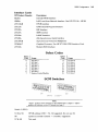
SCM Switches
SW1
SW2
OPEN=O
CLOSED= 1
Note
"Open" position of the switches on the 5CM board is a logic O. "Open"
position of switches on the I/O boards is a logic 1.
Switch 1 (SW1)
Sl thru S5
HP-IB address (LSB = Sl, 30 suggested, Do not use 31)
S6
System Controller (Closed
S7 &S8
Not used.
=
controller, suggested)
3-3
3-4
9050 Configuration
5witch 2 (5W2)
ROM
8KX8
16KX8
32KX8
32KX8
51 &52
51
Open
Closed
Open
Closed
52
Open
Open
Closed
Closed
53&54
Future use.
55 thru 57
Internal HP-IB select code (L5B
=
58
Internal HP-IB Disable (open
disabled)
=
55).
• HP-IB select code = 0 thru 6 .
• I/O slot corresponding to internal HP-IB is empty.
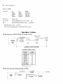
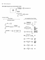
Interface Cables
HP-IB (Internal or HP 27110A/B 110 Interface Card)
HP-IB Connector
(27110-63001) 2m
(Included)
27110AlB
HP-IB Interface
or
~;----g
~
Pin & Socket
Connector
nd
Internal
lsi
Device
HP-IB
Device
2
High Speed: lm'Device Load, 15m Max.
Normal Speed: 2m/Device Load, 20m Max.
Den~~ce
~-J
Available HP-IB Cables
Product
Number
Length
(in meters)
*92220R
108330
10833A
*82977A
108338
*829778
10833C
8120-3448
8120-3449
0.3
0.5
1.0
1.0
2.0
2.0
4.0
6.0
8.0
* Right Angle Connector
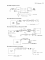
HP 27112A General Purpose Interface (GPIO)
(27112_)
Std. Cable. 5m
Unterminated
(Incluclecl)
27112A
GPIO
Interface
Pin & Socket
Connector
Ar-pt_io_n_OO_l_c_ab_le_.2_.5_m~[]
QJ
(27112_)
5O-Pln F_1e
Connector
9050 Configuration
3-5
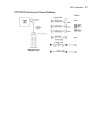
HP 97060A Graphics Processor
Color
Monitor
Such As
HP 13279B
97060A
31BNC, 2m (Included With 97060A)
To 9111A Tablet
HP-IB Cable, Not Included
HP 27122A Remote Job Entry (RJE)
2S-PinE}£-E]
27122A
RJE
Interface
~customer SUPPlied-_ _~1
Pin & Socket
Connector
HP 27123A Shared Resource Management (SRM)
Series2()()
Note: Rcqlllrc=, 97058A --otii.mrt'
rQ
cC:P-
1m
~ToOtherworkstatiOn
'97061 A = 10m
B=25m
C=60m
D = 60m (unterminated)
or SRM Controller
(50961-61600)
0.7M
CONNECTOR
27123A
SRM
INTERFACE
COAX CABLE
HP 27125A LAN Interface Card (LANIC)
METER
CONNECTOR
(27125-63001)
CABLE
(STUB)
[0F>--15
PIN
AUI
or
27125A
AUI
LANIC
CABLE
or
ETHERNET
BRANCH
or
THIN
OPTION
001.
Ethernet Cable (stub)
(27125-63002)
MAU
CABLE
CABLE
3-6
9050 Configuration
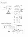
HP 27128A Asynchronous Serial Interface (ASI)
en
nl"'-----llJ
Sld. Cable, 5m
f
F...,.leOB25P(ISD 2110)
(271_)
27128A
ASI
Interlace
Pin & Socket
Connector
_DB25S
Tenninal Cabling
Any of these ...
Ir/--------------------------------~\\
are compatible with any of these.
Ir/-------------------------~\,
ASI Interface Cables
Peripheral
Peripheral Cables
13232N(5m)or
~
M
92219B (15m)
13232U Modem
~ Eliminator
30·Pin
r;1]
~
2647F
13242N (5m) Or
2601 A
ro-------8
2686A
92218A (15m)
2624B (Port 2)
2626A(Port 2)
25·Pin
~,..O....;pt-.-OO-1-Ceb-le---1~
45601 AlB
98844A
2622A. 2623A
2624B (Port 1).
2626A (Port 1).
2627 A. 2703A
50·Pin
40242M (5M)
OR
~
rIt;\
~
2392A OPT.
30~
2392A
25 PIN
f}=
17255D
~
5061-4215
~
92221M
~
82974A
(4.9M)
(105M)
1.5M
==Q
g
g
~
LaMrjel
2686A
9816A1S
9817AIH/L
98626A
98626A
45710A
9807A
9050 Configuration
HP 27130AIB Asynchronous 8-Channel Multiplexer
Peripheral
Peripheral Cable
2647F
27130AlB
ASI
Interlace
2622A, 2623A
26248 (Port 1),
2626A (Port 1),
2627A
0.7 Mf"tf;>rs
(28658-63001 )
(included)
25-Pin
26248 (Port 2)
2626A (Port 2)
SO-Pm Connl'ctor
\-=
I
·~-.l,
-=====-
I
i
~M
~
2601A
Included W!2601
40242M
I
,
Ie
!
-_:.J
~
(5M)
OR
2392A OPT.
~
301
25 PIN
2392A
Female DB25S
R8-232C Connection Panel
(28658-60005, Included)
I1T:l.-
13242G (5M)
£.1h
~::>-----;...:::=~
25 PIN 2888A
3-7
3-8
9050 Configuration
HP 27140A Modem MUX Interface
Peripheral
Peripheral Cables
~n
~
PIN and SOCKET
CONNECTOR
27140A
MODEM
MUX
LI -
2647F
92219B (15m)
3O-Pin
1.0M
(28659-63002)
(included)
13242N (5m) Or
2101 A
~
92218A (15m)
50-PIN
-
2 1248 (Port 2)
2828A (Port 2)
_lAtB
25-Pin
_A
I
2622A, 2623A
2624B (Port 1).
2626A (Port 1).
2627 A. 2703A
FEMALE DB25S
50-Pin
R5-232C Connection Panel
(28659-60005. Included)
19=
M
402421.1
(5M)
OR
2392A OPT. 301
9
25 PIN
172550
..----r.;1h
ro--=-----~
9816AtS
9817AIH/L
98626A
98628A
~==--5-0-6-1---42-1-5~~=~
(4.9M)
£.111
92221M
~=>:::l---=~
45710A
(1.5M)
82974A
----1;:.1h
~=----~
1.51.1
9807A
HP 2285A Local Area Network Interface
1150-1629
15m Branch Cable
(Included, Maximum of 3 (SOm))
~~___(~_1_1~
___1_)______~
____________- ,
27110A
HP-IB
Interface
(Included
WHh Std.
228SA)
QJ
Included
r
LAN Unit
Maximum of
100 Nodes
1150-1627
50 Ohm Terminator
I
Ethernet 1.0 Coax
~
2.SmMin.
SOOm Max.
I
~
4-1
_
I
9050 Troubleshooting
_________________
.
~llcha4~rl
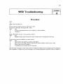
Procedure
Start.
I
S(itch the computer on.
Power indication LEOs and fans OK? (OT - OFF,
Power On - ON, IB - ON, Stack PS - OFF.)
Y1ES
~~rect
overtemperature, power supply, or fans problems.
Chapter 5.
Stack LEOs OK? (On for 112 second then all off.)
YES
NO
Replace faulty stack board then retest. Faulty board corresponds to lit LED.
I
Is terminal or printer available as output device?
YES
NO
Use the I/O card LEOs to indicate card failure.
Use the I/O card cage LEOs to indicate I/O channel failure and I/O error code.
Error code chart in Chapter 5.
Troubleshoot and repair the I/O channels.
Use the error messages on the output device to determine faults. Error messages are in Chapter 5.
Also available, to support the error messages, is a Normal Operation Sequence chart in Chapter 5.
4-2 9050 Troubleshooting
5-1
9050 Diagnostics
.
~________________
~IICM5~~1
_
Reset
Switch
Self-test
Switch
110 Card
Cage LEDs
Processor
Stack Leds
Status
LEDs
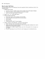
Front Panel LEOs and Switches
Diagnostics Overview
Self-tests run:
• At power on.
• Self-test switch pressed.
• Self-test switch pressed for 3.5 seconds. Press switch again, or cycle power, to terminate the
self-test loop.
Board Self-Tests
The board self-tests reside on each stack board and 110 board that has a microprocessor. The tests
are initiated before the boot loader is transferred to the RAM, and are not dependent on the loader.
The system control module generates the self-test initiation signals.
When a board fails, the sequence stops and the corresponding stack LED is lit. The board before or
after the indicated board may be bad disrupting the initiating signal. Some failures will cause several
LEOs to tum on. The faulty board is the one corresponding to the lowest numbered lit LED. LEOs
that correspond to 1M byte RAM boards will blink while the board is performing its self-test.
If the RAM memory controller is bad, the appropriate LED will light and the self-test will stop.
If an 110 board fails its self-test, an LED on the I/O board will light, and a status signal will be made
available for the loader code to respond to during loader self-tests. Some 110 cards do not have
self-tests (the GPIO for example).
5-2 9050 Diagnostics
Boot Loader Self-Tests
The boot loader performs the following checks and operations before transferring control to the
operating system.
1. Initializes the 1/0 cards:
a. Looks for a device to display system loader messages (starts with Graphics Display).
b. Checks I/O cards for what is available and where it is located.
c. Turns on I/O card cage LEOs for 112 second.
2. Sends Loa de r Re \1_ to the output device.
3. Performs loader I/O self tests:
a.
b.
c.
d.
e.
Checks each select code for interface card and status.
Checks I/O cards and internal HP-lB for self-test failure.
Checks SCM.
Checks I/O bus.
Checks real time clock 0.1 second register.
4. Outputs "System Loader Message" for failed I/O card self-tests.
a. Failure message is sent to the display device and SCM.
b. Select code channel that failed indicated on I/O card cage LEOs and failure error code is
displayed when reset switch is pressed.
c. No indication on LEOs for failed I/O select code in the I/O expander. Error message is on
the display.
d. This error reporting is for a bad I/O card. Later messages are for peripheral devices.
9050 Diagnostics
5-3
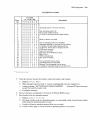
1/0 LED Error Codes.
Error
No.
0
1
2
3
4
5
6
...,
I
8
9
10
11
12
13
14
15
16
17
18
19
20
21
22
23
24
25
I/O LEDs
(1 =on; 0= off)
Description
7 6 5 4 3 2 1 0
o0 0 0 0 0 0 0
000 000 0 1
000 000 1 0
o0 0 0 0 0 1 1
o0 0 0 0 1 0 0
o0 0 0 0 1 0 1
o0 0 0 0 1 1 0
0000011 1
000 0 1 000
o 0 0 0 1 001
o0 0 0 1 0 1 0
o 0 001 011
o 0 001 100
o 000 1 101
o 000 1 1 1 0
o 000 1 1 1 1
000 1 000 0
000 1 000 1
000 1 001 0
000 1 001 1
000 1 0 1 0 0
000 1 0 1 0 1
000 1 0 1 1 0
000 1 0 1 1 1
000 1 1 000
000 1 100 1
*
*
Operating system not found; will retry
*
Bad operating system file
Not enough usable memory
110 card or connected device failed self-test
*
*
Media or device not ready
*
Part of operating system not readable
Attempted address or read past end of volume
Controller/unit failed after passing self-test
110 timeout; device did not respond in time
CS80 error occurred
Tape error occurred
Bad status from HP-IB (110 Card).
Bad 110 bus
NVM chip failed test
RTC chip not ticking
*
Test card found (not an error)
Test Module did not find SCM
Memory Test in progress (not an error)
Looking for Operating System (not and error)
* These codes are not used
5. Tests all memory (except the location where the loader code resides).
a. Displays Test in 9" Me III 0 r>' .
b. Maps salvaged memory back in. Leaves unsalvageable memory mapped out.
c. Loader message "NOT ENOUGH USABLE MEMORY. .. " indicates NO good memory
except that used by loader code.
d. Configures memory.
6. Sets up interleave configuration of memory if 1M byte RAM is used.
7. Boot loader looks for operating system.
a. Displays LooUn9" for Snteill.
b. First pass, loader looks for operating system on removable media. Second pass, loader
will accept first operating system it sees.
c. Loader will ignore operating systems that are not ready.
d. Loader will try again in a few seconds if operating system is not found.
5-4 9050 Diagnostics
8. Loader loads operating system into RAM.
a. Operating system must be HP-UX 4.0 or later.
b. Displays os 1011 ....
c. After "OS 10" number displayed, any error will cause program to stop and output an
error message.
d. Loader checks OS header for required amount of memory. Loads OS or displays
NOT ENOUGH USABLE MEMORY; TOTAL IS XXXX.
9. Displays Load Done.
a. Transfers control to operating system.
b. If pre 4.0 release operating system is used, the computer will stop here. Use an operating
system that is 4.0 or higher.
Operating System Self-Tests
1. Loader self-test results are passed to operating system for:
a. Further evaluation.
b. Recording the status.
c. Presentation as warnings and error messages.
2. OS configures system.
a. Resets 110 bus and runs 1/0 self-tests again.
b. Performs another checksum test of operating system.
c. Assigns I/O device addresses.
3. Record error message information - Operating system records stack self-test information,
and any other error messages for display.
4. Initialize 110 outputs
a. Reinitialize output device for display of OS messages.
b. Initialize 110 outputs for operational tests of devices. Records self-test results of devices.
5. NVM checksum checked. Operating system clock set to RTC.
6. Operating system drivers look at device set. - If no self-test errors on a device set, the 110
card sets up a default structure. OS records the default structure for use by the computer.
7. Display error messages - OS does not use 110 card cage LEOs.
8. Displays copyright messages
9. Run operation - Operating system has completed self-tests.
System Functional Tests
The System Functional Tests are a part of the HP-UX Operating System. They are found in the
CE. Il til i tie s directory. Information concerning these tests can be found in the Series 500 CE
Handbook in the Series 500 HP-UX section (Diagnostics Chapter).
9050 Diagnostics
5-5
LEDs
Stack LEOs
•
•
•
•
•
Directly controlled by stack boards.
Lit for 112 second at start of Board Self-Tests (if a board occupies the slot).
LEDs indicate stack board failure during board self-tests.
LED corresponding to 1M byte RAM boards will blink during self-test.
More than one LED lit; lowest number that is lit corresponds to the failed self-test.
• One LED lit; indicates failed board.
110 Card Cage LEOs
• Controlled by loader self-test program via SCM board.
• Loader self-tests turn on LEDs for 112 second at start of self-tests.
• Self-tests check 110 status lines for pass or fail. Failure of 110 channel, lights the corresponding
LED.
• Reset switch provides an error code for the failed card. Error code gives the same information
as message on display device. Reset switch toggles LEDs between failure and 110 error code.
Status LEOs
Internal Bias (IB)
• Turned on when + 12 volt internal bias voltage is present (AC applied to main power supply).
•
•
•
•
IB on
18 on
IB on
18 on
indicates power applied to computer.
indicates fuse is good.
indicates the computer is turned on
indicates the interlock switch is engaged.
Power On ( + 5 Volt)
• Driven by + 5 volt power supply.
• Indicates main power supply is on.
• Off when power not available to main power supply (lB LED is off).
• Off during overtemperature condition.
• Off during over or under voltage condition (either main power supply or stack power supply).
Self-Test
• Turned on when board self-tests are initiated by SCM.
• Turned off after OS self testing is complete.
Load
• Turned on when boot loader code is loaded into RAM.
• Turned off after operating system is loaded and before control is transferred to the operating
system.
Run
• Controlled by SCM.
• Turned on after completion of OS self-tests.
5-6 9050 Diagnostics
Overt em perature
• Turned on when CPU (slot one), or main power supply is in an overtemperature condition.
• Powered by IB voltage.
• When overtemperature occurs, stack power supply turns off main power supply and turns on
LED.
• LED on indicates power available to internal bias (uses IB to power LED).
• LED on indicates main power supply turned off ( + 5 volt LED off).
• LED on indicates stack power supply off (stack PS LED is off).
Stack Power Supply Board LED
Indicates when one of the stack power supply voltages is overvoltage or undervoltage.
LED on the I/O Board
• Turned on when the I/O card fails the self-test.
• Driven by the 110 board and not dependent on the boot loader.
9050 Diagnostics
5-7
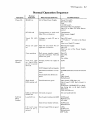
Normal Operation Sequence
Operation
Power On
Self-Tests
(Board).
Normal
Indication
Probable Failure
IB LED on.
AC to Main Power Supply
Power On switch.
AC power cable.
Fuse.
110/220 switch.
Interlock switch not engaged.
Stack PS to Main PS cable disconnected.
OTLEO off.
Temperature in stack and
Main PS is in tolerance.
Temperature
Filter screen clogged.
Fans.
Stack PS LED
off.
Voltages on stack PS are in
tolerance.
Stack PS board.
+ 19 volts or -12 volts to the Stack
PS.
Short on a Stack PS output.
Power On LED
on.
Main PS and Stack PS voltages are in tolerance.
Main Power Supply.
Stack PS.
Short on one of the Power Supply
outputs.
Fans operating
Both power supplies operating and in tolerance. Fans and
drivers are good.
Main PS.
Stack PS.
Fans.
Fan cables.
Self- Test LED
on. Stack LEOs
on for l/Z second
then off.
Primary Power On signal is
good.
SCM.
Stack board
LEOs remain off.
Self-Test
(Boot
Loader)
What Normal Indicates
SCM initiated self-test signals.
SCM.
Motherboard/SCM connections.
SCM/Motherboard connector J4 and
J5.
Stack LEOs and drivers are
good.
LED.
Stack board.
Motherboard.
Stack boards are good.
Stack board (LED that's on).
Stack board (LED that's lowest in
group).
SCM clock (1M RAM LED not blinking during test, or all stack boards
failed test).
CPU (all LEOs on).
LEOs on 110 card 110 cards are good.
remain off.
110 card (with LED lit).
Load LED on.
Boot loader loading into RAM
SCM board.
Motherboard.
I/O cable.
Start of boot loader self-tests.
SCM board.
Motherboard.
110 card cage LEOs are good.
LEOs.
SCM board.
Motherboard.
lOP Cable.
110 card cage
LEOs on for l/Z
second.
5-8 9050 Diagnostics
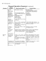
Normal Operation Sequence
Operation
Normal
Indication
(continued)
What Normal Indicates
Probable Failure
"Loader
Rev._" on
output device.
Boot loader is running.
No output device.
Output device failed its self-test.
Output device not powered up.
No System
Loader Error
Messages on
output device (or
I/O card cage
LEOs lit).
I/O cards passed self-tests.
Internal HP-IB passed selftests.
SCM passed self-test.
NVM is good.
1/0 bus is good.
RTC is operating.
110 cards.
"Testing
Memory" on
output device.
Loader memory test is being
performed.
"Looking for
system" on output device.
Boot Loader completed
memory test and has configured memory.
Boot loader is looking for
operating system.
"Not enough usable memory ... " indicates "no" usable memory (except
that used for loader).
"OS 10#_"
on output
device.
Boot Loader found an operating system.
Peripheral. with OS, not ready.
No operating system.
"Load Done"
on output
device.
Operating system is loaded in
RAM and loader transferred
control to operating system.
Refer to System Loader Messages.
Not enough good RAM.
Mass storage device failure.
Error in loading OS.
No Operating
System Error
messages.
Stack, 110 cards. and
peripherals passed OS SelfTests.
OS checksum was checked.
lIO devices were assigned
addresses.
Boot loader ROM and OS revision
level are incompatible or console interface not on select code 0 (OS
stops after transfer of control from
loader).
Refer to Operating System Error
Messages.
Copyright messages displayed.
liO outputs were initialized.
Default structure established.
Failure to find root device. "System
halted" error message.
Self- Test LED
off.
Operating System is ready for
run operation.
SCM board.
Motherboard.
Output device.
Load LED off.
Self-Test
(OS).
Run LED on.
9050 Diagnostics
5-9
Power Indication LEDs
This chart shows the LEDs that are lit for various power supply conditions. It also indicates which
board is the most likely faulty component.
A "I" in the Fault Location column indicates the Stack PS board.
A "2" in the Fault Location column indicates the Main PS Assembly.
A "3" in the Fault Location column indicates the motherboard, or the rest of the sytem.
An undervoltage condition may require the unplugging of stack and lIO boards in order to determine whether a short is in the power supply or the load. A minimum power supply load must be
maintained and the fans must be connected. Any three of the following will maintain the power
supply load:
• One Cpu.
• One lOP.
• Two 512K RAM boards.
• SCM board.
• 09855-66525 load board (used with 9020/9030/9040).
Power Indication LEDs Chart
Fault
(normal)
- 2V undervoltage
- 2V overvoltage
6.7V undervoltage
6.7V overvoltage
3.85V undervoltage
3.85V overvoltage
Stack overtemp
Main supply overtemp
19V undervoltage
19V overvoltage
- 12V undervoltage
5V undervoltage
Overcurrent
+ 12V undervoltage
Line fuse open
IB fuse open
Cable disconnected
Voltage Selector at nov
(220Vinput)
Voltage Selector at 220V
(110V input)
Stack
PS
LED
OT
Power
ON
LED
LED
18
LED
off
on
on
on
on
on
on
off
off
off
off
off
off
off
off
off
off
off
off
off
off
off
off
off
off
on
on
off
off
off
off
off
off
off
off
off
on
off
off
off
off
off
off
off
off
off
off
off
off
off
off
off
off
off
on
on
on
on
on
on
on
on
on
on
on
on
on
on
on
off
off
off
off
off
off
off
off
off
off
on
Fault
Location
1,3 (short)
1,3 (short)
1,3 (short)
1,3 (short)
1,3 (short)
1,3 (short)
CPU, Fan, or 1
Fan, 1, or 2
1,2, or 3
1,2, or 3
1,2,or3
2
1,2, or 3
1,2, or 3
2
2
1,2
Selector Switch
Fuse
Selector Switch
5-10 9050 Diagnostics
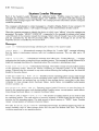
System Loader Message
Each of the System Loader Messages are explained below. Possible causes for many of the
messages are provided. If the message begins with "ERROR:" the system halts after issuing the
message. If the message begins with "NOTE:" the message provides information and the computer
continues operating.
The computer will attempt to output messages to a Graphics Display Station if one is present. If it
can not find a display station, it will output messages to the serial interface at select code O.
Often the computer attempts to identify the device to which it was "talking" when the message was
generated. The trailer "SELECT CODE NN" is appended to the message to indicate which select
code (110 port) of the computer caused the message. Select codes 0 through 7 are on the computer
and are controlled by the first lIO processor (lOP). Select codes 8 through 15 are on the 110
Expander and are controlled by the second lOP.
Messages
La a de r )()()( -
Informational message identifying the revision of the system loader.
T est i n g Me ~I on' ••• - Informational message that follows the "Loader XXX" message indicating
that the loader is performing memory tests and configuring memory. This can take up to 15
seconds.
Loof,ing for S)'ste~I ••• - Informational message that follows the "Testing Memory"," message
indicating that the loader is searching for an operating system. This message is usually followed by a
single line message identifying the operating system the computer is attempting to load.
PIe as e ITIO 1.1 n t n ext ... a 11.1111 e • - Informational message. The loader is ready to load another portion
of the operating system. Mount the volume containing an unloaded portion of the operating
system. Volumes may be mounted in any order without affecting the loading process, but must be
loaded in the same device.
SYSTEM NOT FOUND; WILL RETRY IN )o()(-Unable to find an operating system on any mass storage
device. The loader will attempt to find an operating system again in XXX seconds. Possible causes:
mass storage device not powered up, no media in mass storage device, wrong disc in disc drive,
computer or mass storage device hardware failure, media failure, incompatible loader/system
revision numbers, etc.
BAD SYSTEM FILE: SELECT CODE NN - Operating system loaded. However, an error has been detected in the operating system code during loading. Possible causes: corrupt system, media failure,
mass storage hardware failure, or computer hardware failure.
NOT ENOUGH USABLE MEMORY; TOTAL IS )CCO( - The amount of usable memory is too small to load
the operating system. The total amount of memory required is 98304 bytes plus the amount of
memory for the operating system. The total amount of good memory is "XXXX" bytes. Possible
causes: corrupt system or hardware (memory) failure.
BAD CARD OR DEi.1 I CE: SELECT CODE NN - Informational message. A hardware failure has been detected (interface card or mass storage device did not pass the Module Self-Test). The loader
continues searching for an operating system.
9050 Diagnostics 5-11
MEDIA/DE!.IICE NOT READY: SELECT CODE NN - While loading. The media (Volume) was removed
from the device (e.g. a floppy disc was pulled out of a disc drive), the device went offline, or a
hardware problem caused the device to become "not ready".
UNRECo!.IERABLE DATA: SELECT CODE NN - Part of the operating system is not readable. Possible
causes: media failure or mass storage device hardware failure.
END OF !.loLUME: SELECT CODE NN - Attempt to address or read past the end of a volume. Possible
causes: corrupt system, media failure or mass storage device hardware failure.
CTRLR/UNIT FAULT: SELECT CODE NN - Hardware passed initial self-test. However, It failed while
being used to load the operating system. Possible causes: computer (interface card) hardware
failure or mass storage device hardware failure.
Io TIMEOUT: SELECT CODE NN - Mass storage device failed to respond fast enough while attempting
to load from it. Possible cause: computer hardware failure, mass storage device hardware failure, or
the media was removed during loading.
CS80 DEVICE: SELECT CODE NN -
Indicates a mass storage device hardware failure.
TAPE DE!.IICE: SELECT CODE NN -Usually indicates a tape device (HP 7971A, HP 7974, HP 7978)
hardware failure. Can also indicate a failure on the HP 27110A HP-IB Interface. Tape errors
covered are: "Command Rejected", "Interface Busy", "Rewinding", "Tape Runaway", "Data
Timing Error", and "Command Parity Error".
HP I B CARD: SELECT CODE NN - Transaction to the indicated HPIB interface card was terminated
due to a probable interface card failure.
SCM NOT FOUND. -
Indicates a computer hardware failure on the computer's System Control
Module.
BAD Io BUS: SELECT CODE NN - Indicates a computer hardware failure on the computers first lOP,
or a bad SCM. The lOP does a write/read to the SCM during this test.
BAD NVM: SELECT CODE NN -
Indicates that Non-Volatile Memory failed its self-test. Possible cause:
SCM failure.
BAD RTC: SELECT CODE NN -
Indicates that the built in Real Time Clock is not operating correctly.
5-12 9050 Diagnostics
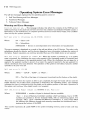
Operating System Error Messages
The self-test messages displayed by the operating system consist of:
1. Self-Test Waming and Error Messages.
2. Fatal Error Messages.
3. Software Failure Messages
Warning and Error Messages
C1 0 c f, art d d ate rt 0 t set. - This message indicates that either the contents of the NVM are not
valid at powerup or the clock has not been set since this condition was detected. Possible causes: a
bad battery on the SCM board, or computer powered down for more than 2 weeks. The condition
does not stop the system operation.
Self test error 1: liD address AA, SS STATUS: XXXXXXXX
Where:
AA = Select code
SS
=
Subaddress
XXXXXXXX
Device or card dependent error information (in hexadecimal).
=
This error message is displayed as a result of the self-test failure of an I/O device. The select code
subaddress denote the device, and the device dependent error information indicates the nature of
the failure. System operation can continue provided that use of the failed device is not required.
Self test error 2: CHECKSUM for Se9fTiertt NN - When the system is powered up, or a system
reset is executed, the checksum for every code segment of the operating system is computed and
compared to a checksum in the operating system code. When the checksums do not agree for a
segment, the segment number is stored. As a result, the segment reported is the last segment for
which a checksum error was detected. The operation of the system is not halted, however, further
operation is at your own risk.
Self test error 3: XXXX NN
Where:
XXXX
=
NN
The Nth of that type of component (counting from the bottom of the stack).
=
"CPU#", "IOP#", or "MC#_".
This error occurs when the system is able to get completely through the board self-test and the
loader self-test, but a failed stack component is detected by the operating system. The message
indicates the type of component which has failed and its relative position in the stack. Operation of
the system can continue, if the failed board is not required.
Self test error 4: MeMOry reduced to: NNNNNNNN Bytes. MCs:<llst>
Where:
NNNNNNNN
=
number of bytes (in decimal) that are available.
<list> = A list of Memory Controller numbers which had failures. Up to 10 MC
numbers are printed in 10 two character fields, with no intervening spaces. For
example: "MCs: 1 210" indicates that Memory Controllers 1, 2, and 10 have failed
the memory test. Memory boards (and memory controllers) are numbered from 1,
starting at the bottom of the RAM.
This number represents all usable RAM in the system including memory used to hold code segments.
9050 Diagnostics 5-13
S elf t est err 0 r 5: Fewer fin s t rat e s we ref 0 un d t han ex pee ted. - This message is displayed
when the number of boards recorded in the Non-Volatile Memory (NVM) is greater than the actual
number of boards in the stack. If the number of boards in the stack is greater than the number
stored in the NVM, the number in the NVM is updated to reflect the larger stack size.
Fatal Error Messages
SysteM halted due to double bit MeMOry error on MC
Where:
NN
=
#
NN CCCCCCCC
MC #
CCCCCCCC
=
Last healer content for that MC (in hexadecimal).
This message is displayed when a double bit error has been detected by the memory controller
hardware. The MC# is in terms of memory controller boards (counting up from the bottom of the
stack). This information is also recorded in the NVM.
If more than one MC with a double bit error is found, only the last error is displayed. If no double bit
errors are found, but the CPU was interrupted for a double bit error, "No DBE found" replaces NN
XXXXXXXXX. DBE information is stored in the NVM.
SYSTEM_HAL TED: I 1"1 s uf fie i er,t MenlO n' to s tart s \'S t elri - This message is displayed when there
is insufficient memory for the operating system and user subsystem. Check the stack self-test lights
to see if any stack components have failed self-test. Also, check the memory configuration of the
computer to see if it is large enough to accomodate the system and options which are being loaded.
SYSTEM HALTED: lnCOlrlpatible lOPs - This message indicates that an illegal combination of lOP
boards were found at power up. lOPs of Revision 2.1 or earlier are not compatible with lOPs of
Revision 2.2 or later.
System Error Message
Sy s t elll hal ted - >SYSTEM ERROR: •••• -
This message is displayed when the operating system soft-
ware encounters either:
• an unanticipated trap,
• an unrecoverable system software error.
The "trap" is distinguished from the software error by the word "trap:" which is added to the first
line of the message.
Before displaying any messages, the currently executing CPU disables its interrupts and causes all
other CPUs to stop operating. The message text is mUltiple lines information dumped from memory
and internal registers. The message starts on the top line on the Display and overwrites any other
messages on the CRT. If a printer is the output device and the message is more than 25 lines in
length, the message continues to print (up to 500 lines).
5-14 9050 Diagnostics
6-1
9050 Adjustments
.
'_----________________
~llcM6~~1
There are no field adjustments in the HP 9050 Computer.
6-2 9050 Adjustments
7-1
9050 Peripherals
.
~llcM7~rl
'--__________________
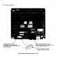
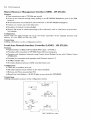
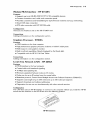
Interface Cards
HP-IB Interface - HP 27110A/B
Features
• IEEE-488-1978 compatible.
• Supports DMA with two modes of performance: High Speed Mode for operation with fixed
discs or other high speed peripherals; Standard Mode for instruments and slower peripherals.
• Supports up to 14 device loads.
• Selectable as HP-IB controller or slave.
• Built in hardware self-test.
Configuration
Normal switch settings are as follows (note that up is the open switch position and represents a logic
one).
Sl-S5:
Address 30 (decimal); Sl is least significant bit; Address 31 is illegal and causes a
flashing LED on the HP-IB card.
S6:
System Controller On; When the switch is up the HP-IB is the system controller for
the HP-IB bus.
S7:
Normal Speed; Up for normal speed; Also called Data Settling Time Selection switch
as it changes the time delay to meet IEEE Standard 488-1978 for high speed
devices. An in-line resistor pack must also be moved when changing the speed, if the
HP-IB is the system controller.
S8:
Self Test Mode 1; Down for self test mode 1.
High speed devices can run on a normal speed bus, but run slower than their capacity. Normal
speed devices cannot run on a high speed bus. The following are examples of high speed devices:
• Disc drives
• 7971A tape drives
• 2608S 2631B/G printers
Connections
Cabling information is in the configuration section.
7-2 9050 Peripherals
LOAD RESISTOR PACK
IN NORMAL-SPEED POSITION
OR IF NOT SYSTEM CONTROLLER
IN HIGH SPEED
MOVE LOAD RESISTOR PACK
HERE FOR HIGH-SPEED OPERATION
AND SYSTEM CONTROLLER
S7:
-UP FOR NORMAL SPEED
-DOWN FOR HIGH SPEED
HP 27110A/B HP-IB Interface Card
9050 Peripherals 7-3
General Purpose Interface (GPIO) - HP 27112A
Features
• Choice of programmable operating modes (clocked or transparent) for ease of use with instrumentation.
• 5upports + 5 V level on all input and output signals, plus an optional + 12 V level on output
signals.
• Programmed data detection for either positive true or ground true levels.
• Independent 16 bit input and output buses and storage registers.
• Two control and two status lines.
Configuration
Normal switch settings depend on which peripheral device is connected to the GPIO. The 97060A
Graphics Processor requires the following GPIO switch settings. When the switch is up, it is in the
open position.
The switches correspond to:
5W1
51: DIN;
Up - Positive True.
Down - Negative True.
52: CT5 and 5T5;
Up - Positive True.
Down - Negative True.
53: P5ET;
Up - Positive True.
Down - Negative True.
54: PDIR;
Up - Positive True.
Down - Negative True.
55: DOUT;
Up - Positive True.
Down - Negative True.
56: PEND
Up - Positive True.
Down - Negative True.
57: PFLAG
Up - Positive True.
Busy - High.
Ready - Low.
Down - Negative True (HP 97060A).
Busy - Low.
Ready - High.
58: PCNTL;
Up - Positive True.
Active - High.
Idle - Low.
Down - Negative True.
Active - Low.
Idle - High.
7-4 9050 Peripherals
5W2
51:
Bidirectional Bus Enable:
Up - Disabled.
Down - Enabled.
52:
Internal Handshake Enable;
Up - Disabled.
Down - Enabled.
53:
Full/Pulse Handshake Enable;
Up - Disabled.
Down - Enabled (HP 97060A).
54 and 5S: Data Input Clock 5elect;
Both Down - Backplane sync cycle completion.
Both Up - Backplane sync cycle completion.
54 Up and 5S Down - Busy to ready edge of PFLAG
(trail edge)
54 Down and 5S Up - Ready to busy edge of PFLAG
(lead edge)
Ensure that jumpers WI, W2, and W3 are in the correct position.
It may be necessary to increase the delay on the GPIO card. Use the following procedure.
Two one-shots (ElS) on the GPIO card generate the write delay and the internal handshake
delay. The write delay one-shot provides approximately 100 nsec for the output data to settle.
When extra long cables are used, or when the peripheral device requires additional settling time
for the data, the delay can be increased by adding a capacitor between pins 1 and 4 of the
socket at E16.
The formula for selecting the capacitor value is:
C = (T-I00)/1.S
Where: C = Added Capacitance (in pf)
T = Total time delay (in nsec)
The internal delay one shot provides a delay of approximately 3 usec between the assertion of
PCNTL and the assertion of FLAG. The delay can be increased by adding a capacitor between
pins Sand 8 of the socket at E16.
The formula for selecting the capacitor value is:
C = (T-3000)/3
Where: C
T
=
=
Added Capacitance (in pf)
Total time delay (in nsec)
Connections
Cabling information is in the configuration section.
9050 Peripherals 7-5
W1. W2. W3
Jumper in 5V Position
Jumper in 12V Position
+5 el:i:!J+12
S7:
-UP FOR 9885M/S
-DOWN FOR 97060A
-uP FOR 9885M/S
-DOWN FOR 97060A
HP 27112A General Purpose I/O Interface Card
Remote Job Entry Interface (RJE) - HP 27122A
Features
• 1 200 to 19 200 baud rates.
• Compatible with EtA RS- 232C and CCITT V.24 specifications.
• Supports Bell type 208B, 2096, and 212 data sets or equivalent.
• Supports Siemens MSV2 protocol.
• Works with full or half duplex modems, and supports AUTO ANSWER and ORIGINATE.
• Provides link control functions: line bid, normal and transparent data modes, all responses,
and link termination.
• Assures data integrity with CRC error checking.
• EBCDIC character recognition.
• Space compression/truncation.
Configuration
There are no switches to be set on the RJE Card.
Connections
Cabling information is in the configuration section.
7-6 9050 Peripherals
Shared Resource Management Interface (SRM) - HP 27123A
Features
• Data transmission rate is 700 Kbits per second.
• Access to the network through rotary polling on an HP 98028A Multiplexer (part of the SRM
product).
•
•
•
•
All transmissions are broadcast to all connections on the HP 98028A multiplexer.
Packets can contain up to 512 data bytes.
Reception of packets is acknowledged.
Remote file access to create/open/purge a file or directory, read or write bytes, set protection,
and catalog.
Configuration
Ensure That the eight switches are set to the binary equivalent of the assigned decimal node
address. S 1 is the MSB, and S8 is the LSB.
Connections
Cabling information is in the configuration section.
Local Area Network Interface Controller (LANIC) - HP 27125A
Features
• Implementation of IEEE LAN standards 802.2 type 1 and 802.3.
• Provides LAN connection to HP 9000 Series 500 host computers.
• Operates with baseband networks using Carrier Sense Multiple Access with Collision Detect
(CSMA/CD).
• Provides for connection and operation with Ethernet version 1.0.
• 10 Mbps transfer rate.
• 50 metres distance between LANIC and attachment unit.
Configuration
• There are no switches to be set.
• All node hardware must conform to the same standards.
• Remove and throwaway jumper W3.
• Record the link Address - 08 00 09 (plus xx yy zz from the NOVRAM).
Connections
Cabling information is shown in the configuration section.
I
J1
I
I/o
U26
c=:J
CHANNEL
CONNECTOR
NOVRAM
•• (W3)
c::::r:::J
JUMPER
FUSE
(Removed for
9000 Series 500)
HP
EPROM
c:::::J c=:J
U97
U95
LEOs
REO GREEN
LAN
CONNECTOR
QQ
II ,
l'---__----'J ~ ________. . ;=====1
,.~------
CARD
CONNECTOR
CABLE
9050 Peripherals 7-7
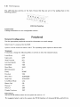
Asynchronous Serial Interface (ASI) - HP 27128A
Features
• Switch selectable and software programmable baud rate; up to 19 200 bits per second.
• EIA RS-232C, CCnT V.28 compatible.
• Asynchronous transmission in simplex, full duplex, and echoplex mode.
• Programmable format control and built-in framing error, overrun error, and parity checking.
• Break detection, support for X-ON or X-OFF and terminal emulation mode.
Configuration
The normal switch settings are:
S1: Single Text Termination;
Up - Single Text Termination. (Typical)
Down - Not Single Text Termination.
S2: Hard wired;
Up - Device directly connected.
Down - Device Not Directly Connected.
(Modem use)
S3: No Parity;
Up - No Parity. (Typical)
Down - Odd Parity.
S4: Bits Per Character;
Up - 8 Bits Per Character. (Typical)
Down - 7 Bits Per Character.
S5 to S8: Baud Rate; (See table)
ASI Baud Rate Switches
Switches
S5
S6
S7
S8
BAUD Rate
Down
Down
Down
Down
Down
Down
Down
Down
Down
Down
Down
Down
Down
Down
Down
Up
Up
Down
Up
Up
Up
Up
Down
Down
Down
Up
Up
Down
Up
Up
Up
Up
Up
Up
Up
Up
Down
Down
Down
Down
Down
Down
Down
Up
Up
Down
Up
Up
Up
Up
Down
Down
Down
Up
Up
Down
50
75
110
134.5
150
300
600
900
*1200
1800
2400
3600
4800
7200
**9600
19200
* Typical modem
** Typical direct connection application
Connections
Cabling information is in the configuration section.
Up
Up
Up
Up
Up
Up
Up
Up
7-8 9050 Peripherals
HP 27128A Asynchronous Serial Interface (ASI) Card
Asynchronous 8-Channel Multiplexer Interface - HP 27130AlB
Features
• CCITT V.28 and EIA RS-232C compatible.
• Supports simplex, echoplex, or full duplex mode (asynchronous transmission only).
• Selection of data transmission attributes can be performed independently on each channel.
• Local intelligence reduces time consumed by the CPU during I/O transactions by offering edit
functions, special character recognition, and handshake protocol control.
• Parity, overrun, and framing errors are sensed locally to detect transmission errors.
• X-ON or X-OFF (both directions) and ENQ/ACK (one direction, host sending ENQ) handshaking.
Configuration
There are no switches to be set on the multiplexer card.
Connections
Cabling information is in the configuration section.
9050 Peripherals 7-9
Modem MUX Interface - HP 27140A
Features
• Supports up to six EIA RS-232C/CCIlT-V.22 compatible devices.
• Consists of interface card, cable, and connection panel.
• Provides control lines and handshaking for asynchronous modems and uucp networking.
• Direct DCE style connection.
• DTE style connection with HP 92219Q cable.
Configuration
There are no switches to set on the HP 27140A card.
Connections
Cabling information is in the configuration section.
Graphics Processor - 97060A
Features
• GPIO interface to the host computer.
• High performance graphics processor; 8 planes of 1024 X 1024 pixels.
• RGB output to color graphics monitor.
• Built in self-test capabilities. Results displayed by the Ready light.
• Compatible with the HP 9111A Data Tablet.
Connections
Cabling information is in the configuration section.
Local Area Network (LAN) - HP 2285A
Features
• HP-IB interface to the host computer.
• Coaxial cable with baseband signaling
• 10 Mbps data signaling rate.
• Minimum separation between nodes is 2.5 metres.
• Nodes can be up to 40 metres from the coaxial cable.
• Masterless protocol, Carrier-Sense Multiple Access with Collision Detection (CSMA/CD).
• Segment coax length of up to 500 metre and up to 100 nodes per segment.
• Supports broadcast and multicast addressing.
• Diagnostics the user can run Simultaneously with other network services.
Configuration
The LAN Unit uses an HP-IB interface to connect to the computer. Before you install the HP-IB
ensure that the switches on the HP-IB are set to the following position.
HP-IB Switches
7-10 9050 Peripherals
The LAN Unit has switches on the back. Ensure that they are set to 0 by putting them in the
following position.
LAN Unit Switches
Connections
Cabling information is in the configuration section.
Peripheral
General Configuration
Use the appropriate peripheral manual for information on switch settings.
Select Code 7 is reserved for the SCM.
System console should use select code O. The operating system expects to find it there.
Terminals
If necessary, change the following fields or switches to have the indicated values.
Local Echo
OFF
Caps Lock
OFF
Xmit Fnctn(A)
NO
Inh Hnd Shk(G)
YES
Inh D2(H)
YES
Baud Rate
9600
Bits/Characters
8
Parity
NONE
Enq Ack
YES
Recv Pace
XON/XOFF
Xmit Pace
XON/XOFF
Line/Block Mode
Line
Return Def
CR
Remote
*
ON
Auto LF
OFF
Display Functions
OFF
Disc Drives
Set the HP-IB address switch for the system disc drive to "0".
The suggested select code for the system disc HP-IB interface is 5 (Internal HP-IB or HP 27110).
9050 Peripherals 7-11
Supported Peripherals
This list is current as of publication of this manual. Due to the frequent change of this list it is
recommended that you contact the HP Sales Representative for current information about this
equipment.
Modems
Use 27128A or 27140A Interface.
HP Product Number
Description
37212A
QTD 300/1200 Baud Modem.
92205A1C
Hayes 1200 Baud Modem.
Terminals
Use HP 27128A or HP 27140A Interface.
HP Product Number
Description
2382A
Alphanumeric Terminal.
2392A
Alphanumeric Terminal.
2622A
Alphanumeric Terminal.
2623A
Graphics Terminal. HP 17623A is the Tablet for the HP 2623A Terminal.
2627A
Color Graphics Terminal. HP 17623A is the Tablet for the HP 2627A
Terminal.
45610AlB
HP 150 when used as HP 2623 Terminal.
45710A
HP 110 when used as a terminal emulator.
97056A
BASIC Terminal Emulator.
97076A
"Aterm" HP-UX Terminal Emulator.
9807A
Integral PC
98700A
Graphics Display Station
98790A
Series 200 Terminal Emulator.
7 -12 9050 Peripherals
Mass Storage
Use HP 27110A/B HP-IB.
HP Product Number
Description
7911P/R
28.1M byte Disc Drive with a 67M byte Tape Cartridge.
7912P/R
65.6M byte Disc Drive with a 67M byte Tape Drive.
7914P/R
132.1M byte Disc Drive with Two 67M byte Tape Drive.
7933H
404M byte CS/80 Disc Drive.
7935H
404M byte CS/80 Disc Drive.
7941A
24M byte Disc Drive.
7942A
24M byte Disc Drive.
7945A
55M byte Disc Drive.
7946A
55M byte Disc Drive.
7974A
Tape Drive, 9 track, 1600 cpi.
9122D/S
3 112 inch Flexible Disc Drive.
9125S
5 114 inch Flexible Disc Drive.
91330
14.5M byte Winchester Disc Drive and 3 112 inch Flexible Disc Drive.
91340
14.8M byte SS/80 Winchester Disc Drive.
9144A
114 inch Cartridge Tape Drive.
9895A
8 Inch Flexible Disc Drive.
Printers
Use HP 271lOA/B HP-IB.
HP Product Number
Description
2225A
Thinkjet Dot Matrix Printer, 150 cps.
2563A
Line Printer, 300 lpm. (Shade - 26061A - GPIS for Printer)
2565A
Impact Printer, Dot Matrix, 600 lpm.
2566A
Impact Printer, Dot Matrix, 900 lpm.
2602A
Impact Printer, Daisywheel, 25 cps
2671A/G
Dot Matrix Thermal, 120 cps.
2673A
Intelligent Printer. 120 cps.
2686A
Laser Printer, 6 ppm.
2688A
Laser Printer, 12 ppm.
2932A
Impact Graphics Printer, 200 cps.
2933A
Impact Graphics Printer, 200 cps, with fonts and bar code.
2934A
Impact Graphics Printer, 200 cps, without bar code, with letters.
9050 Peripherals
Plotters
Use HP 27110AIB HP-IB.
HP Product Number
Description
7470A
Pinchroll Plotter, A size, 2 Pen.
7475A
Pinchroll Plotter, B size, 6 Pen.
7550A
Plotter, B size, 8 Pen.
7580AlB
Plotter, D size, 8 Pen.
7585A1B
Plotter, E size, 8 Pen.
7586B
Roll Feed Plotter, E size, 8 Pen.
9872crr
Plotter, B size, 8 pen.
Miscellaneous
HP Product Number
Description
9111A
Tablet. Use HP 27110A HP-IB.
13279B
Color Monitor, 19 Inch. Uses HP 97062A Color Output Interface.
26075A
HP-IB Switch
27116A
HP-CIO Extender
92211L
Taboret Cabinet Rack
92211R
Design Plus Mobile Mini Rack
97064A
CAD Worktable
97098A
110 Expander (Needs a Second lOP in the Stack.)
46087A
A size Graphics Digitizer.
46088A
B size Graphics Digitizer.
46089A
4 Button Cursor (for Digitizers).
98028A
SRM Multiplexer.
7-13
7·14 9050 Peripherals
8-1
_
9050 Replaceable Parts
L . . . . . - . -_ _ _ _ _ _ _ _ _ _ _ _ _ _ _ _
.
~llcM8~~1
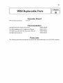
Extender Board
HP-CIO Extender Board
27116A
Documentation
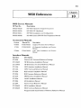
HP 9050 Hardware Support Document
09050-90038
HP 9050 Installation and Configuration Manual
09050-90011
HP 9000 Series 200/500 Site Preparation Manual
09000-90040
HP 9050 CE Handbook
09050-90035
Parts Lists
The following parts lists and explodes identify all the replaceable parts for the HP 9050 computer.
8-2
9050 Replaceable P arts
5
(PARTIAL)
16
22
/
23
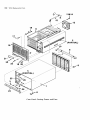
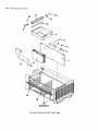
Case, Pan e,I Casting , F rame, and Fans
9050 Replaceable Parts 8-3
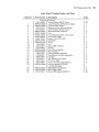
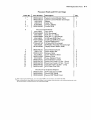
Case, Panel, Casting, Frame, and Fans
Part Number
I Description
5
6
7
8
9
10
11
12
13
14
15
16
17
18
19
20
21
22
23
Common
0515-0825
09050-04402
09050-61608
0510-0174
0515-0825
09050-21201
09121-48303
09050-64301
09050-40201
5041-1203
09050-47701
09050-00102
3160-0458
0515-0964
2190-0009
09050-61604
09050-04401
1390-0720
2190-0011
2950-0208
2190-0057
1600-1353
0515-0080
09050-61606
24
25
26
09050-29501
09050-29502
0515-0219
Hardware
ScrewlWasher (M4 X 7mm)
Case Assembly (with feet and slides)
Ground Cable (Steel)
Retainer, Screw (Ground Strap)
Screw/Washer (M4 X 7mm)
Slide Assembly (2 Pieces)
Feet
Front Panel Assembly (with insert)
Front Panel Insert
Button, Line (ON, OFF)
Light Pipe
Frame
Fan
Screw (M4 X 45mm)
Washer
Fan Cable Assembly
Rear Casting
Latch Assembly (all parts)
Star Washer (for latch assembly)
Cap Nut
Star Washer (for Frame)
I/O Cover Plate
Screw, I/O Cover Plate (M3.5)
Uninterruptable PS (UPS)
Cable Assembly
RFI Gasket (top/bottom)
RFI Gasket (sides)
Screw, RFI Gasket (M3XO.5)
Index No
1
2
3
4
Qty
42
1
1
1
1
2
4
1
1
1
1
1
2
4
4
1
1
1
1
4
4
1
2
1
2
2
18
8-4 9050 Replaceable Parts
Power Supplies
9050 Replaceable Parts
Power Supplies
Index No.
Part Number
Description
*
09050-66587
09050-69587
09050-61601
2110-0051
2110-0342
2110-0269
09050-01206
2110-0360
09050-07902
09050-67901
09050-01204
09050-01205
09050-01203
09050-04101
09050-66585
09050-69585
09050-61603
09050-07901
09050-24101
3050-0071
Main Power Supply (New)
Main Power Supply (Exchange)
Cable Assembly (ON/OFF Switch)
Fuse (lOA-110V)
Fuse (8A-250V)
Fuse Cap
Power Switch Bracket
IB Fuse (3/4A)
Stack Power Supply Cover
Filter/Interlock Cable Assembly
Interlock Cover
Interlock Bracket
AC Receptacle Bracket
AC Receptacle Cover
Stack Power Supply Board (New)
Stack Power Supply Board (Exchange)
Stack Power Supply Cable
Bus Bars
Air Baffle (Plastic)
Flat Washer (Air Baffle)
1
2
3
4
5
6
7
8
9
10
11
12
13
14
15
16
17
Power Cords
United States (llOV)
8120-1378
United States (220V)
8120-0698
Australia
8120-1369
Europe
8120-1689
8120-2104
Switzerland
Denmark
8120-2956
South Africa
8120-4211
* Includes items 2 thru 6
Qty
1
2
1
1
8-5
8-6 9050 Replaceable Parts
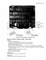
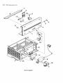
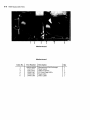
Processor Stack and 110 Card Cage
9050 Replaceable Parts 8-7
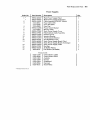
Processor Stack and 1/0 Card Cage
Index No.
Part Number
Description
*
09050-66510
09050-69510
1420-0302
1400-0719
8159-0005
09050-80000
System Control Module (New)
System Control Module (Exchange)
Battery
Cable Ties
Jumper, Battery
Loader ROM
1
2
3
4
5
**
6
Processor Stack Boards
5061-6803
CPU (New)
97043-69803
CPU (Exchange)
5061-6806
lOP, Rev. 3.1 (New)
97044-69806
lOP, Rev. 3.1 (Exchange)
5061-6805
512K byte RAM (New)
97047-69805
512K byte RAM (Exchange)
5061-7704
1M byte RAM (New)
97046-69704
1M byte RAM (Exchange)
lOP Buffer Assembly (No Exchange)
5061-4228
98700-66583
Display Station Buffer (DSB)
7
09050-44101
7200-1750
09050-01201
0515-0825
09050-01202
0515-0635
09050-24701
09050-44703
09050-44 704
09050-44702
09050-61605
8
9
10
11
12
13
14
15
16
17
Stack Retainer Bucket
Stack retainer Bar
Retainer Slider
Screw (Retainer Slider)
Retainer Hook
Screw (Retainer Hook)
Stack Retainer Cushion
Stack Card Guide (13 Slot - Short)
Stack Card Guide (12 Slot - Short)
110 Card Guide (12 Slot - Long)
lOP Cable (First lOP)
Qty
1
2
1
1
1
2
2
2
2
4
2
1
1
2
1
Not Shown On Exploded Diagram
09050-616071 lOP Cable (Second lOP)
09050-40601
Second lOP Shield
09050-40602
Second lOP Shield Cover
* When replacing the SCM board, move the loader ROM to the new board. Use tool 8710-0585.
**When ordering the Loader ROM, the serial number of the computer must be given to the individual taking the order.
The serial number is programmed into the replacement ROM.
8-8 9050 Replaceable Parts
2
3
4
5
6
Motherboard
Motherboard
Index No.
Part Number
Description
1
2
3
09050-66500
3101-2777
3101-2777
1990-1037
1990-1037
1990-1036
Motherboard (No Exchange)
Reset Switch
Self Test Switch
I/O Card Cage LEOs
Stack LEOs
Status LEOs
4
5
6
Qty
1
1
1
2
3
1
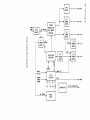
AC IN
LINE
FILTER
FUSE
+
~
+
z....
~
~nl
~
D.C. FANS
+8.5 TO
+15.5 VOLTS
.... ;u
c'"
;Ul:
z~
0'"
I
+
~
+
~
~
...,
<
I/O CARD CAGE
....
~
~
~
iI:T!
~
VI
r-
POWER SUPPLY
~
i;UT!
L
PROCESSOR STACK
Z
1
....
POWER FAIL WARNING (PFW)
~
!II
TWO
j
.....
PRIMARY POWER ON (PPON)
MAIN
POWER
SUPPLY
AC SWITCH
INTERLOCKj--. 110/220 SWITCH
SWITCH
r
(UP
TO 7 I/O CARDS)
-----+-
~
PERIPHERALS
STACK TEt.APERATURE
MAIN P.S.
OVERTEt.APERATURE
3
PERIPHERAL ADDRESSES
1ST lOP CABLE
;U
~
~
50
"~
c!
VI
~I
"
~ "
i.-
0
Z
~
ill
;U
+3.85 ......
VI
+6.7 .....
;§
~
~
~
-2
J:
----±14
J:
~
(UP
36 t.AHz
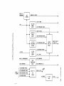
UNINTERRUPTABLE
POWER SUPPLY
CONNECTOR
SYSTEM CONTROL
MODULE
1+-.~
~
TO
12 CARDS)
INITIATE
SELF-TESTS
(SCM)
DISPLAY
STATION INTERRUPT
+ "
U1~
VI
~I
~
;U
~
~
~
0
z
~
to
I
8
t
STATUS
I/O SELF-TEST
LEOS
LEOS
12
z
~
~
J:
"iiiI
r
50
PROCESSOR STACK
to
STACK
SELF-TEST
LEOS
~.
50
2ND lOP CABLE
(OPTIONAL)
1.0
~
PFW
CIRCUIT
PFW
\0
0
<.n
0
00;.
to
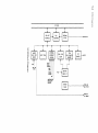
POWER
CORD
INPUT
CIRCUITS
-
1
I
ENERGY
STORAGE AND
HALF BRIDGE
AC VOLTAGE
r
P:ER
SUPPLY
SWITCHING
if
+5V
19V
POWER
SUPPLY
+19V
b
-4-12V
+19V
PULSE WIDTH
MODULATOR
i
i!;l
0
REMOTE
lURN OFF
~
REF
VOLTAGE
SUPPLY
-12V
POWER
SUPPLY
-..
.
r--+
~
-12V
+12V
POWER ~ +12V
SUPPLY
POWER OFF
FAULT
DETECTION
PPON
PPON
i i i
+5V
LINE SENSING
f+-
FEEDBACK
+5V
PRIMARY
CURRENT
SENSING
@
+5V
POWER
SUPPLY
-12V
+12V
RESET
CRKTS
~
;Q
CI
!:l
TEMPERATURE
TO STACK POWER SUPPLY
~
STACK P.S.
TEMPERATURE
VARIABLE FAN VOLTAGE
FAN
CONTROL
~
+6.7V TO STACK
+6.7 VOLT
POWER
SUPPLY
+19V
+6.7V OVER/UNDER VOLTAGE
+3.85V TO STACK
..
~
+3.85 VOLT
POWER
SUPPLY
+19 VOLT
OVER/UNDER
VOLTAGE
r
+3.85V OVER/UNDER VOLTAGE
+19V OVER/UNDER VOLTAGE
~
-2 VOLT
POWER
SUPPLY
-12 VOLTS
MAIN P.S. OVERTEMPERATURE
~ OVER/UNDER VOLTAGE
{
REMOTE
TURN OFF
CIRCUIT
REMOTE TURN OFF
TO MAIN P.S.
OVER/UNDER VOLTAGE
~
TO STACK
OVER TEMPERATURE
OVER
TEMPERATURE
CIRCUIT
STACK TEMPERATURE
+6.7V OVER/UNDER VOLTAGE
-~
-""
..
STACK P.S .
LED
DRIVER
OVER TEMPERATURE LED
~
(-P
STACK P.S. LED
r-------------~~
IB VOLTAGE
18 LED
DRIVE
IB LED
lOP BUS
. - - - - - - - - - - - _ HP-IB BUS
LEOS
SELF TEST
SWITCH
UNINTERRUPTABLE
POWER SUPPLY
CONNECTOR
SYSTEM
CLOCK
t-----------_~ =T~~ ~~S
______________________________________
~ST~K
SELF
TEST SIGNALS
9050 Diagrams
MEMORY
!
MEMORY
CPU
!
MEMORY
!
MEMORY PROCESSOR BUS
lOP
(CHANNEL
ADAPTER)
I/O BUS (I/O CHANNEL)
110 Channel Interconnections
!
9-5
9-6 9050 Diagrams
Reset
Switch
Self-Test
Switch
I/O Card
Cage LEOs
Processor
Stack LEOs
Front Panel LEDs and Switches
Self-Test
I B Power
Supply
Over
Temperature
Status LEDs
Load
Run
Power
On
Status
LEOs
10-1
9050 References
9050 Service Manuals
HP Part No.
Description
09050-90038
HP 9050 Hardware Support Document
09050-90035
HP 9050 CE Handbook
09050-90011
HP 9050 Installation and Configuration
09000-90040
HP 9000 Series 200/500 Site Preparation Manual
Accessories Manuals
Product
Manual No.
97060A
97060-90030
Graphics Processor Service Manual
Description
97098
97098-90020
I/O Expander Installation and Service
Manual
97064A
97064-90000
CAD Table Installation and Service
Manual
Interface Manuals
Interface
Description
27132A
Channel 110 Technical Reference Package
271lONB
HP-IB Interface Installation Manual
271lOA/B
HP-IB Interface Technical Reference Manual
27112A
GPIO Interface Installation Manual
27112A
GPIO Technical Reference Manual
27122A
RJE Interface Installation Manual
27122A
RJE Firmware Reference Manual
27123A
SRM Interface Installation Manual
27125A
LANIC Installation Manual
27128A
ASllnstallation Manual
27128A
ASI Technical Reference Manual
27130A/B
MUX Installation Manual
27130A/B
MUX Technical Reference Manual
Programmable Serial Interface Hardware Reference Manual
Chapter
10
10-2 9050 Reference
HP-UX Users Documentation
HP Part No.
Description
09000-90007
HP-UX Reference
97073-90005
IMAGE HP-UX Reference Supplement
98680-90025
Introducing the UNIX System by McGilton & Morgan
97089-90004
HP-UX Concepts and Tutorials (4 Vols.)
97089-90048
HP-UX System Administrator's Manual
97080-90093
Unpacking Instructions for the HP 9000 Series 500 Computers
92836-90005
Stuctured FORTRAN 77 Programming by Pollack
97081-90001
FORTRAN/9000 Reference
92832-90002
Programming in Pascal by Grogono
97082-90001
Pascall9000 Reference
97089-90000
The C Programming Language by Kernighan & Ritchie
97086-90001
Applications Migration Reference
97086-90002
Applications Migration Users Guide
97059-90000
HP-UX Local Area Network (LAN) Users Guide
97059-90001
HP-UX LAN Node Manager's Guide
97076-90001
HP-UX Asynchronous Communications User's Guide
97077 -90000
RJE Synchronous Data Communications User's Guide
97084-90000
DGL Programmer Reference
97084-90001
DGL Supplement for the Series 500
97084-90025
Graphics/9000 Device Handlers Manual
97085-90000
AGP User's Guide
97085-90001
AGP Supplement for the Series 500
97085-90005
AGP Reference
98183-90000
HP SPICE User's Guide
98183-90005
HP SPICE Reference
11-1
9050 Service Notes
Keep your service notes in this section.
Chapter
11
09050-90601
Mfg. No. Only