1
Technical Manual
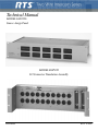
MODEL SAP1626
Source Assign Panel
MODEL BOP220
I/O Connector Translation Assembly
9300420000
Rev F 11/2006
PROPRIETARY NOTICE
The product information and design disclosed herein were originated by
and are the property of Telex Communications, Inc. Telex reserves all
patent, proprietary design, manufacturing, reproduction, use and sales
rights thereto, and to any article disclosed therein, except to the extent
rights are expressly granted to others.
COPYRIGHT NOTICE
Copyright 2006 by Telex Communications, Inc. All rights reserved.
Reproduction, in whole or in part, without prior written permission from
Telex is prohibited.
WARRANTY NOTICE
See the enclosed warranty card for further details.
SHIPPING TO THE MANUFACTURER
All shipments of product should be made via UPS Ground, prepaid (you
may request from Factory Service a different shipment method). Any
shipment upgrades will be paid by the customer. The equipment should
be shipped in the original packing carton. If the original carton is not
available, use any suitable container that is rigid and of adequate size. If
a substitute container is used, the equipment should be wrapped in paper
and surrounded with at least four (4) inches of excelsior or similar
shock-absorbing material. All shipments must be sent to the following
address and must include the Proof of Purchase for warranty repair.
Upon completion of any repair the equipment will be returned via
United Parcel Service or specified shipper, collect.
Factory Service Department
Telex Communications, Inc.
8601 East Cornhusker Hwy.
Lincoln, NE 68507 U.S.A.
Attn: Service
CUSTOMER SUPPORT
This package should include the following:
Technical questions should be directed to:
Customer Service Department
RTS/Telex Communications, Inc.
12000 Portland Avenue South
Burnsville, MN 55337 USA
Telephone: 800-392-3497
Fax: 800-323-0498
RETURN SHIPPING INSTRUCTIONS
Customer Service Department
Telex Communications, Inc. (Lincoln, NE)
Telephone: 402-467-5321
Fax: 402-467-3279
Factory Service: 800-553-5992
Please include a note in the box which supplies the company name,
address, phone number, a person to contact regarding the repair, the type
and quantity of equipment, a description of the problem and the serial
number(s).
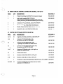
TABLE OF CONTENTS
Il
i-, PROPRIETARY NOTICE
. . . . . . . . . . . . . . . . . . . . . . . . . . . . . . . . . . . ..
.... . . . . . . . . . . ii
COPYRIGHTNOTICE . . . . . . . . . . . . . . . . . . . . . . . . . . . . . . . . . . . . . . . . . . . . . . . . . . . . . ii
UNPACKING AND INSPECTION . . . . . . . . . . . . . . . . . . . . . . . . . . . . . . . . . . . . . . . . . . . . . . ii
WARRANTYINFORMATION . . . . . . . . . . . . . . . . . . . . . . . . . . . . . . . . . . . . . . . . . . . . . . . . ii
RETURN SHIPPING INSTRUCTIONS . . . . . . . . . . . . . . . . . . . . . . . . . . . . . . . . . . . . . . . . . . . . ii
.................................
1-1
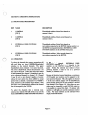
SECTION 1: DESCRIPTION AND SPECIFICATIONS
1.1DESCRlPTION
1-1
1 2 SPECIFICATIONS: SAP1626
1-2
1.3 SPECIFICATIONS: BOP 220
1-2
SECTION2.INSTALLATION
2-1
2.1 MECHANICAL II'BTALLATION
2-1
2.2 ELECTRICALINSTALLATION
2-1
2.2.1 ELECTRICAL INSTALLATION. POWER
2-1
2.2.2 ELECTRICAL INSTALLATION. SIGNALS
2-1
2.2.3 REAR PANEL DESCRIPTION . . . . . . . . . . . . . . . . . . . . . . . . . . . . . . . . . . . . . . . . . . 2.11
SECTION 3: OPERATING INSTRUCTIONS
3-1
3.1 FRONT PANEL DESCRIPTION
3-1
320PERATION
3-1
4-1
SECTION 4: THEORY ON' OPERATION
4.1 OVERALL FUNCTIONAL DESCRIPTION . . . . . . . . . . . . . . . . . . . . . . . . . . . . . . . . . . . . . . . 4-1
4.2 PROGRAM CHANNEL DESCRlPTlON . . . . . . . . . . . . . . . . . . . . . . . . . . . . . . . . . . . . . . . . 4-2
4.3 ~ O P 2 2 DESCRIPTION
0
. . . . . . . . . . . . . . . . . . . . . . . . . . . . . . . . . . . . . . . . . . . . . . . 4-2
......................................................
..............................................
..............................................
...............................................
............................................
.............................................
....................................
...................................
......................................
L
.............................................
........................................................
...
....
... .... ... .
'
.
I
"i7
". .'5
-=
......
.....
.
.
,i ;..: >$>.
I
'
~
I
I
~
I
..r .
........................................
...............................................
"
..
.z.
.
>
~'
.
SECTION5:MAINTENANCE
5-1
5.1INTRODUCTION . . . . . . . . . . . . . . . . . . . . . . . . . . . . . . . . . . . . . . . . . . . . . . . . . . . . . 5-1
5.2 SERVICE INFORMATION . . . . . . . . . . . . . . . . . . . . . . . . . . . . . . . . . . . . . . . . . . . . . . .
5.3GENERALMAINTENANCE . . . . . . . . . . . . . . . . . . . . . . . . . . . . . . . . . . . . . . . . . . . . . .
5.3.1 SAFETY CONSIDERATIONS
5.3.2 CLEANING
5.4 PERFORMANCE CHECK . . . . . . . . . . . . . . . . . . . . . . . . . . . . . . . . . . .
5.4.1VISUAL . . . . . . . . . . . . . . . . . . . . . . . . . . . . . . . . . . . . . . . . . . . . . . . . . . . . . .
5.4.2TURN-ON . . . . . . . . . . . . . . . . . . . . . . . . . . . . . . . . . . . . . . . . . . . . . . . . . . . . .
5.4.30UTPUTCHECK
5.4.4 TALK TEST 1
;.................................................
5.4.5TALKTEST2 . . . . . . . . . . . . . . . . . . . . . . . . . . . . . . . . . . . . . . . . . . . . .
5.4.6 TALK TEST 3
5.4.7 TALK TEST4 . . . . . . . . . . . . . . . . . . . . . . . . . . . . . . . . . . . . . . . . . . . . . . . . . . . .
5.4.8 TALK TEST 5
5.4.9 TALKTEST6
5.4.10 PROGRAM TEST
5.4.11 CAMERA OUTPUTS TEST
5.5TROUBLESHOOTING . . . . . . . . . . . . . . . . . . . . . . . . . . . . . . . . . . . . . . . . . . . . . . . . . .
5-1
5-1
5-1
S-1
5-1
5-1
5-1
5-2
5-2
5-2
5-2
5-2
5-3
5-3
5-3
5-4
5-7
..........................................
......................................................
..............
.
.................................................
...................................................
...................................................
....................................................
................................................
...........................................
-Page iii-
TABLE OF CONTENTS (Continued)
....................................
SECTION 6: LISTS OF REPLACEABLE PARTS
6-1 i
6.1INTRODUCTION . . . . . . . . . . . . . . . . . . . . . . . . . . . . . . . . . . . . . . . . . . . . . . . . . . . . . 6-1
6.1.1 DIVISION OF PARTS LISTS . . . . . . . . . . . . . . . . . . . . . . . . . . . . . . . . . . . . . . . . . . . 6-1
6.2 HOW TO OBTAIN PARTS
6-1
6.3SHIPPINGLISTS
6-1
6.3.1 SAP1626 . . . . . . . . . . . . . . . . . . . . . . . . . . . . . . . . . . . . . . . . . . . . . . . . . . . . . . 6-1
6-1
6.3.2BOP220
6.4 SAP1626 FINAL ASSEMBLY.9010.394 9.00
6-2
6-1
6.5 SAP1626 BACK PANEL. 9020-3866-00
6-3
6.6 PRINTED CIRCUIT ASSEMBLY CONNECTOR ADAPTER.9030.402 5.00
6-3
6.7 PRINTED CIRCUIT BOARD SWITCH. 9030-3871-00
6-4
6.8 SAP1626 TRIPLE CURRENT LIMITER ASSEMBLY (OPTIONAL). 9030- 1602-00
6.9 BOP220 FINAL ASSEMBLY (2ND GENERATION).9010.468 9.00
6-4
SECTION A: APPENDIX A
A-1
A.l GENERAL INFORMATION AND DEFINITIONS
A- I
A.2 DETAILEDINFORMATION . . . . . . . . . . . . . . . . . . . . . . . . . . . . . . . . . . . . . . . . . . . . . . A- I
SECTION B: APPENDIX B
B-1
B.l GENERAL INFORMATION AND DEFINITIONS . . . . . . . . . . . . . . . . . . . . . . . . . . . . . . . . . . . B- I
B.2DETAlLEDINFORMATION . . . . . . . . . . . . . . . . . . . . . . . . . . . . . . . . . . . . . . . . . . . . . . B- I
SECTION7:DIAGRAMS
7-1
................................................
.....................................................
.......................................................
......................................
.........................................
.....................
.................................
................
..........................
................................................
...................................
.................................................
.................................................
-Page iv-
/
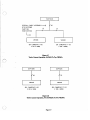
SECTION 1: DESCRIPTION AND
SPECIFICATIONS
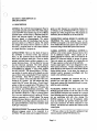
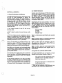
1.1 DESCRIPTION
GENERAL The SAP1626 Source Assignment Panel is
a manually operated matrix switch. This switch assigns
each of 20 TW*User Station strings to two of fifteen
possible buses. Twelve buses can distribute both DC
power and intercom signals. Three buses distribute
intercom signals or program signals. The matrix
switch has the effect of transforming a basic two bus
intercom system to a fifeen bus system. The switch
also assigns six camera intercom stations to a pair of
intercom / program buses or twelve camera stations
to a single intercom / program bus.
SAP1626 BUSES There are three kinds of buses in
the SAP1626: 1) two-way two-wire type intercom
buses, 2) DC powered two-way two-wire intercom
buses, and 3) program audio buses. There are twelve
primary intercom buses and three program or secondary intercom buses. All buses allow for two-way
two-wire intercom operation. The twelve primary
buses may also be "powered" buses. The powering is
accomplished by plugging TW type power supplies
into the SAP1626. The powering allows a TW intercom station to receive power on its channel one wire
(one of three wires connecting the TW user station to
the SAP1626). Most TW user stations require DC
power to appear across two of the three wires connecting it to a system. (The TW stations that don't
require this DC power either have a "Local Power"
option or they are a special kind of TW station.) The
two wires that accept DC power on a TW station are
the common and [CHannel One] connections. This
means that, in general, the upper row of switches on
the SAP1626 should be set only to powered buses.
Up to ten user stations may be in a group of TW user
stations connected to a SAP1626 output. The twenty
outputs discussed above are available on the back of
the SAP1626 on two frfty-conductor connectors, or on
the optional BOP220 as twenty three-conductor male
XLR type connectors.
PROGRAM BUSES Three program buses allow three
different program sources to be connected to a
SAP1626. TW user stations can be assigned these pro-
grams on their channel two connection (bottom row
of switches on the SAP1626).If TW user stations are
assigned one of the program buses with program not
connected, the bus functions as an intercom bus.
CONNECTING SAP1626 BUSES TO MODEL 802
CIlANNJ3L.S The twelve primary buses of the
SAP1626 correspond to the twelve balanced channels
of the Model 802 intercom systems and can be interconnected using a Model 862 System Interconnect.
CAMERA OUTPUTS / OPTIONAL OUTPUTS In
addition to the twenty outputs discussed above, there
are six additional outputs. These outputs are intended primarily for cameras, but can be used for additional TW intercom stations or groups of stations.
These six outputs are available on a twenty-five pin
"DM
type connector on the back of the SAP1626.
Camera output pairs 1thru 6 are designated for television camera intercom. Output connections can be
made directly to each camera or to the Model VIE306
Station-Isolate System. In the latter, the outputs are
switched and/or processed accordingly and then
routed to the individual cameras.
PACKAGING: SAP1626 The SAP1626 fits into a
standard two unit high EIA equipment rack. The
front panel contains the thumbwheels used to accomplish the matrix switching.
PACKAGING: BOP220 The three rack unit high
BOP220 generally mounts on the rear rails of a rack
panel. BOP220 connectors are mounted on a recessed
panel allowing space for mating connectors and cables
yet not interfering with rack door closing. The
BOP220 connects to the two 50-conductor cables
from the SAP1626 and provides twenty male XLRtype 3-pin connectors for direct connection to user
stations. All external user station lines connect to this
central point.
* TW here refers to the two-wire unbalanced type
intercom system sold by RTS Systems, Inc.
Page 1-1
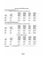
Maximum Switch
Carrying Current
Maximum Switch
Breaking Current
Inputs
Full duplex lines
Program Inputs
Outputs (Two Channel)
User Station
Camera*
Program Input:
Impedance
Level
Power Requirements
Size
Weight (Mass)
Color
2.0 amperes per output
0.5 amperes per output
800 ohms
No external power required; Power distributed from RTS Systems
Power Supplies: PS30 or PS31,
3.468 inches (88 millimeters) high by 19 inches (483 millimeters)
wide by 9.825 inches (298 millimeters) deep (Allow another 4.0
inches (102 millimeters) depth for cables on rear panel.)
10 pounds (4.55 kilograms)
Grey, Fed. Std #595A-26492
13 SPECIFICATIONS**: BOP 220
Inputs
Two 50-pin male microribbon connectors (Amphenol Type Series
Outputs
Size
Twenty 3-pin male XLR-type connectors
5.25 inches high by
19 inches wide by
5 inches deep
Weight (Mass)
2.53 pounds (1.1kilograms)
Finish
Gold Irridite
57)
*
**
Camera Outputs can be adapted to 12 single-channeloutputs.
Note: These specifications are subject to change without notice.
Page 1-2
SECTION 2: INSTALLATION
I
2.1 MECHANICAL INSTALLATION
The Model SAP1626 mounts in a standard 19 inch
rack, in a space two rack units high (3.5 inches). The
BOP220 should be mounted in the same rack as the
SAP1626 behind the SAP1626.
Figure 2-2 shows the wiring of a four-conductor
cable**.
2.2 ELECTRICAL INSTALLATION
F i e 2-3 shows the wiring of a twenty-fiveconductor cable.
2.2.1 ELECTRICAL INSTALLATION, POWER
F i e 2-4 shows wiring of a program Input cable.
The SAP1626 distributes DC power and signals but
no power is required to operate the SAP1626 itself
and there are no power connections.
Figure 2-5 shows how to wire a TW User Station cable to plug into one of the twenty BOP2U) outputs.
2.2.2 ELECTRICAL INSTALLATION, SIGNALS
The electrical installation of the SAP1626 requires
one to four four-conductor shielded cables, two f@conductor cables, and optionally, a twenty five-conductor cable, and microphone cables.
(3
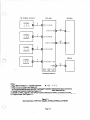
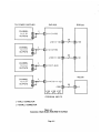
Figure 2-1 shows interconnection of a SAP162.6,
BOP220,l to 4 TW Power Supplies**,and a VIE306.
The one to four four-conductor cables are used to
connect one to four TW* Power Supplies, respectively, to the SAP1626 "INTERCOM CHANNEL
INTERCONNECT" inputs.
Figure 2-6 shows the interconnection of the SAP1626
to a TW/802 Series type intercom system.
Since the SAP1626 has no current limiters, PS50 and
PS60 power supplies may shorten the life of the
thumbwheel switches, but current limiters may be
added to the SAP1626. See Appendix B for a triple
current limiter,circuit assembly. To protect all 12 active buses of the SAP1626 requires 4 assemblies.
(Continued, overleaf)
The two fifty-conductor cables connect the SAP1626
"EXTERNAL USER STATIONS" "OUTPUTS" to
the BOP220 "CONNECTIONS TO SAP1626, J121,
5122".
The twenty five-conductor cable connects the
SAP1626 "INTERCONNECTION TO VIE306
MODEL 306" outputs to the VIE306, CIF612, or directly to the cameras or optionally, user stations.
* TW here means the RTS Systems, Two Wire Intercom system which combines DC power and unbalanced intercom signals. One channel requires two
wires, two channels, three wires, et cetera.
The microphone cable connects program sources to
the SAP1626.
The SAP1626 program input
impedance is 800 ohms. Typical levels to feed into the
program input ranges from OdBm to -lOdBm.
** If the TW Power Supply is a PS30 made before
mid 1983, see Appendix A for instructions on how to
connect the PS30 supplies to the SAP1626
Alternatively, program inputs can used to monitor optional channels 13, 14, 15. (via a 10 kilohm bridging
amplifier)
Page 2-1
2 2 2 ELECTRICAL INSTALLATION, SIGNALS
(Continued)
ME306 CONNECTIONS Figure 2-1 shows how to
connect a VIE396 to the SAP1626. This approach
provides two channels of two-wire intercom per
channel. Only the lower set of camera thumbwheel
switches are processed by the VIE306 electronics to
provide station isolate and two wire to four wire
conversion. The upper row of camera thumbwheel
switches appears at the rear panel of the VIE306
unprocessed and in the two-wire plus DC format.
Two VIE306's may be used for a 12 camera installation. These two VIE306's may be connected in one of
two ways.
The frrst way is with special cable RTS Systems part
number 9020-2976-00. Connections are shown in Figure 2-7. This cable sends the upper row of CAMERA
thumbwheels, normally [Channel 11 for Cameras 1-6
1, to one VIE306 as Cameras 1-6. The lower row of
CAMERA thumbwheels, which are normally
[Channel 21 for Cameras 1-6, to a second VIE306 as
Cameras 7-12. The disadvantage of this method is that
there is only one channel per camera, however if the
cameras are being operated in the 4wire mode the
second channel is generally not used.
The second method, for a 12 Camera installation, requires two SAP1626's and two V I E W S as shown in
Figure 2-8. The advantage of this method is that two
channels per camera are available and may be selected via the two rows of thumbwheels.
Page 2-2
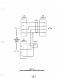
TW POWER SUPPLIES
SAP 1626
BOP220
w
CHANNEL
1,2.3
OUTPUTS
4
El
f
I
&] JI 11 (1-2-3)
J l O l (1-10)
CHANNEL
1 , 2 . 3
OUTPUTS
El
[I
50
II
[a
J122
4
f
I
B] J 1 12 (4-5-63
VIE306
J114 (10-11-12)
"
+
PROGRAM INPUTS
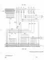
Notes:
1. M = Male Connector: F = Female Connector.
M=B F=D
2. Four Conductor Cable: See Figure 2-2 .
3. F i y Conductor Cable is f i e foot ribbon cable with insulation displacement type connectors:
RTS Systems Model Number 4015-5F / RTS Systems Part Number: 9020-2970-00 .
4. Twenty fie-Conductor Cable See Figure 2-3.
5. VIE306 or CIF612, optional. See CIF612 Technical Manual for CIF612 connection and wiring details.
6. Program Inputs: See Figure 2-4
.
Figure 2-1
Interconnection of TW Power Supplies, SAP1626, BOP220, and VIE306
Page 2-3
A4F
CABLE
CONNECTOR
A4M
CABLE
CONNECTOR
SHIELD
TO POWER
SUPPLY
1
1
2
2
3
3
4
LJ
4
u
u
Figure 2-2
Four-ConductorCable Wiring Diagram
Page 2-4
PIN
TO
SAP 1626
CONNECTION
COMMON
COMMON
COMMON
COMMON
COMMON
COMMON
COMMON
COMMON
COMMON
COMMON
COMMON
COMMON
NOT USED
CAMERA 1
CAMERA 2
CAMERA 3
CAMERA 4
CAMERA 5
CAMERA 6
CAMERA 1
CAMERA 2
CAMERA 3
CAMERA 4
CAMERA 5
CAMERA 6
CHANNEL
CHANNEL
CHANNEL
CHANNEL
CHANNEL
CHANNEL
CHANNEL
CHANNEL
CHANNEL
CHANNEL
CHANNEL
CHANNEL
1
1
1
1
1
1
2
2
2
2
2
2
Figure 2-3
'benty-Five Conductor Cable Wiring Diagram
Page 2-5
FROM
BALANCED
PROGRAM
SOURCE
A3F
CABLE
A34M
CABLE
CONNECTOR
'ONNECToR
AUDIO
AUDIO
GROUND
Figure 2-4
Program Cable Wiring Diagram
Page 2-6
TO
SAP 1626
A3F
CABLE
TO BOP220
USER STATION
OUTPUT
CHANNEL (23
CHANNEL 113
COMMON
A34M
CABLE
CONNECTOR
CONNECTOR
TO
TW USER
STATION
SHIELD
3
3
2
2
1
1
Notes:
1.
Channel [I] refers to the top row of thumbwheel switches on the SAP1626, or the Channel 1switch
position on a two-channel TW User Station Channel Selector Switch.
2.
Channel [2] refers to the bottom row of thumbwheel switches on the SAP1626, or the Channel 2 switch
position on a two-channel TW User Station Channel Selector Switch.
3.
Using two individually shielded wires in the cable will provide less crosstalk than a standard
microphone cable.
Figure 2-5
User Station Cable Wiring Diagram
Page 2-7
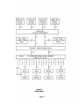
4
MODEL 8 0 2
MASTER
STATION
MODEL 802
MASTER
STATION
MODEL 8 0 2
MASTER
STATION
MODEL 802
MASTER
STATION
i
1/50
/'
50
50
/'
50
-
MODEL 862
SYSTEM INTERCONNECT
"4
/'4
4
PS31 THREE
CHANNEL POWER
SUPPLY
4
/
/
/
I
//4
PS31 THREE
CHANNEL POWER
SUPPLY
/'4
>
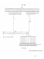
SAP1626 / SOURCE ASSIGN PANEL
I
I/O CONNECTOR TRANSLATION ASSEMBLY
(BREAK OUT PANEL)
I
1
2
3
4
5
6
7
8
9
10 11 12 13 14 15 16 17 18 19 2 0
STATIONS
CM300
RMS300
BP300
Figure 2-6
System Diagram
Page 2-8
-+
SAP 1626
SPECIAL CABLE ASSEMBLY
RTS SYSTEMS
12
PART NO.
/
9020-2976-00
I
1 2 5
13
/
I
I
SIX CAMERAS (1-61
2 OR 4 WIRE
I
SIX CAMERAS (7-12)
2 OR 4 WIRE
Figure 2-7
Twelve Camera Operation, SAP1626 To Two VIE306's
SAP 1626
/'25
-
VIE306
J
SIX CAMERAS (7-12)
2 OR 4 WlRE
SIX CAMERAS (1-6)
2 OR 4 WlRE
Figure 2-8
'helve Camera Operation, l b o SAI'1626's To "bo VIE306's
Page 2-9
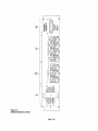
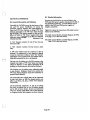
Figure 2-9
Model SAP1626 Rear Panel
Page 2-10
(~..2.23 Rear Panel Description
REF
NAME
OUTPUTS
50-pin female microribbon connectors.
Outputs from front-panel EXTERNAL
thumbwheel switches to the BOP2U).
6
PROGRAM
INPUTS
3-pin female XLR-type program input
connectors. Accept line-level
audio input.
7
POWER SUPPLY
INPUTS
Cpin female XLR-type connectors.
Power supply inputs from a PS30 or
PS31.
8
OUTPUTS TO
VIE306
%-pin female D connector. Outputs
from front-panel CAMERA thumbwheel
switches. Connects to optional
WE%.
Page 2-11
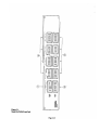
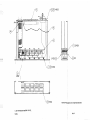
Figure 3-1
Model SAP1626 Front Panel
Page 2-12
\ .. ,
)
SECTION 3: OPERATING INSTRUCTIONS
3.1 FRONT PANEL DESCRIPTION
REF NAME
DESCRlPTION
1
CAMERAS
CH 11
r
Thumbwheel switches. Select first channel on
cameras 1thru 6.
2
CAMERAS
[CH 21
Thumbwheel switches. Select second channel on
cameras 1thru 6.
3
EXTERNAL USER STATIONS
[CH 11
Thumbwheel switches. Select first channel on
user stations connected to the BOP2U). Station numbers on
the BOP2U) correspond directly to EXTERNAL USER
STATIONS numbers on the SAP1626 front panel.
4
EXTERNAL USER STATIONS
[CH 21
Thumbwheel switches. Select second channel on
user stations connected to the BOP2U).
3.2 OPERATION
To select the channels that camera user stations will
talk and listen on, turn CAMERAS thumbwheel
switches to the desired channels. The upper
thumbwheel selects channel 1 on camera intercom.
The lower thumbwheel switch selects channel 2 on
the camera intercom. Unless the camera user station
is local powered the channel 1thumbwheel must be
set to a powered channel, i.e. channels 1-12. Channel
2 may be set to any channel regardless of power,
unless the user station has been modified to accept
power from a channel 2 connection.. If a VIE306 is
used, channel 2 is the isolated "isoed" channel. Thus
the lower row of thumbwheels will select the channel
that is interupted by the VIE306.
To select the channels that the external (noncamera) user stations will talk and listen on, turn the
desired EXTERNAL USER STATIONS thumbwheel
to the desired channel.
EXTERNAL USER
STATIONS numbers correspond directly to the
numbers on the BOP220 Connector Translation
panel. Unless the external user station is local
powered, channel 1 must be set to a powered
channel, i.e. channels 1-12. '
Because of electrical current limitations, a maximum
of 30 headset user stations can be assigned to the
same powered channel. This only applies to channel
1 of the user stations (upper row of thumbwheels)
and is because power for the user stations is derived
from channel 1(see Figure 4-1). More than one user
station can be connected to each SAP1626 output so
it is possible to exceed this limit. If stations with
speakers or call lights are used the maximum number
is less. For exact numbers see the relevant Power
Supply Technical Manual.
Page 3-1
12 lN1ERWU LINES
(UNBALANCED1
TERMINATE
M U S E D INPUTS
SELECTION TO INTERCOM CHANNEL 1
SELECTION TO INTERCOM PROGRAM I
BALANCED
PROGRAM
INPUTS
TW OR 800 SERIES
F i r e 4-1 / SAP1626 Block Diagram
/
I
Page 3-2
-
SECTION 4: THEORY OF OPERATION
I
4.1 OVERALL FUNCTIONAL DESCRIPTION
(See Figure 4-1)
GENERAL The SAP1626 Source Assignment Panel
is a rack-mounted matrix switch. This switch assigns
each of 20 TW* User Station strings to two of fifteen
possible buses. Twelve buses can distribute both DC
power and intercom signals. Three buses distribute
intercom signals or program signals. The matrix
switch has the effect of transforming a basic two bus
intercom system to a fifteen bus system. The switch
also assigns six camera intercom stations to a pair of
intercom/program buses or twelve camera stations to
a single intercom/program bus.
.
I*
I
\?
SAP1626 BUSES There are three k i d s of buses in
the SAP162.6: 1) two-way two-wire type intercom
buses, 2) DC powered two-way two-wire intercom
buses, and 3) program audio buses. There are twelve
primary intercom buses and three program or secondary intercom buses. All buses allow for two-way
two-wire intercom operation. The twelve primary
buses may also be "powered" buses. The powering is
accomplished by plugging TW type power supplies
into the SAP1626. The powering allows a TW intercom station to receive power on its channel one wire
(one of,.threewires connecting the TW user station to
the SAP1626). Most TW user stations require DC
power to appear across two of the three wires connecting it to a system. (The TW stations that don't
require this DC power either have a "Local Power"
option or they are a special kind of TW station.) The
two wires that accept DC power on a TW station are
the common and [CHannel One] connections. This
means that, in general, the upper row of switches on
the SAP1626 should be set only to powered buses.
Up to ten user stations may be in a group of TW user
stations connected to a SAP1626 output. The twenty
outputs discussed above are available on the back of
the SAP1626 on two fifty-conductor connectors, or on
the optional BOP220 as twenty three-conductor male
XLR type connectors.
PROGRAM BUSES The three program buses allow
three different program sources to be connected to
the SAP1626. The TW user stations can be assigned
these programs on their channel two connection
(bottom row of switches on the SAP1626). If the TW
user station is assigned one of the program buses as
above but there is no program connected, the bus can
then function as an intercom bus.
BUS CONNECTIONS: 1 TO 12 On the SAP1626,
twelve intercom unbalanced powered or unpowered
intercom inputs are tied to SAP1626 thumbwheel
switch buses one through twelve via INTERCOM
CHANNEL INTERCONNECT connectors, 5111,
5112, 5113, J114. Each connector ties three intercom
channels to three buses respectively. (See SD3871).
The contacts can handle a contact carrying current of
2.0 amperes and a contact breaking current of
0.5 amperes.
BUS CONNECTIONS: 13 TO 15 Three balanced
program inputs at the rear panel on connectors labeled "PROGRAM INPUTS" (J105, J106, 5107) tie
to buses 13,14, and 15.
USER STATION CONNECTIONS The front panel
thumbwheel switches tie the EXTERNAL USER
STATION outputs to one of 15 buses. At the
BOP220 each XLR 3-32 connector ties to an upper
thumbwheel and a lower thumbwheel in a column, so
that a TW user station plugged into one of these connectors has its "Channel one and its Channel two selected by a column of switches.select these 15 buses.
The "EXTERNAL USER STATION" switches connect through two 50-conductor rear-panel external
output connectors, J101, 5103, which normally connect via two 50-conductor flat cables to the BOP220.
The BOP220 wiring converts the two 50-conductor
connectors to twenty 3-pin XLR-type connectors.
Thumbwheel switches S13-S52 select channels for
EXTERNAL outputs labeled 1-20 on the BOP220.
Odd numbered switches are top row and select intercom channel 1. Even numbered switches are bottom
row and select intercom channel 2. Outputs from
these switches connect to rear-panel microribbon
connectors JlOl and 5103.
Page 4-1
CAMERA CONNECTIONS
The front panel
thumbwheel switches tie the camera outputs to one
of 15 buses.and The camera thumbwheel switch outputs are available on a rear panel 25-pin female "D"
connector. An optional Camera Iso Electronics,
Model VIE306, can be connected the 25 pin "D" connector.
Note that the lower row of camera thumbwheel
switches, labled [CH 21, select the channel that is to
be isolated by the VIEW.
Thumbwheel switches S1-S12 select the channels for
cameras 1-6. Odd numbered switches are the upper
row and select the camera's intercom channel 1.
Even numbered switches are lower row and select the
camera's intercom channel 2.
Output from these first 12 switches connects to rearpanel D connector J8.
4 3 BOP220 DESCRIPTION
(See SD 4689, Section 7)
Two-wire intercom audio plus 32 volts DC from the
SAP1626 connects to the BOP220 at 5121 and 5122
male 50-pin micro-ribbon connectors. The micraribbon connectors are wired to the 20 XLR-3-32 type
male output connectors on the BOP220. A pair of
intercom channels appear on each XLR-3-32. On
each XLR-3-32, pin 1is common, pin 2 is a channel
or bus selected by the upper row of switches on the
SAP1626, and pin 3 is a channel selected by the bottom row of switches on the SAP1626, The
"EXTERNAL OUTPUT" number of the XLR-3-32
connectors corresponds to the column numbers on
the SAP1626. Thirty two volts DC may appear on an
XLR-3-32, pins 2 and 3, referenced pin 1. To operate
TW User Stations, pin 2 must have t 18 to +32 volts
DC on it with reference to pin 1(common). The exception to this rule are TW User Stations with "Local
Power Option", or TW or other stations operating in
the balanced mode, including Series 800.
4.2 PROGRAM CHANNEL DESCRIPTION
(See SD3871 in Section 7)
The three program channels have identical circuitry.
Program 1 will be used as an example. Program 1
enters through rear-panel XLR-3-31 connector, J105.
Capacitors C1 and C2 prevent direct current from
damaging the transformer, TI, if a cable carrying DC
is accidently connected to the program inputs.
The transformer, TI, converts the 800 ohm balanced
input to a 200 ohm unbalanced line. The resistor, R1,
establishes the 200 ohms. The 200 ohm unbalanced
line can also serve as a "dry"RTS Systems TW bus
Capacitor C7 protects the transformer from direct
current from the RTS line.
Page 4-2
,.-~,'
SECTION 5: MAINTENANCE
5.4 PERFORMANCE CHECK
5.1 INTRODUCTION
EQUIPMENT NEEDED
This section provides service information for normal
maintenance, factory performance tests and troubleshooting.
5 3 SERVICE INFORMATION
The Model SAP1626 is warranted for a period of one
year from the purchase date. The warranty and return instructions are in the front of this manual.
5 3 GENERAL MAINTENANCE
53.1 SAFETY CONSIDERATIONS
These servicing instructions are for qualified personnel only. To avoid electric.shock, do not perform any
servicing other than that contained in the operating
instructions unless qualif~edto do so.
Service and adjustments should be performed only by
qualified service personnel.
If fuses are used, be certain that only fuses with the
required current rating and of the specified type
(normal blow, time delay, slo--blo, etc.) are used for
replacement. The use of repaired fuses and the
short--circuitkgof fuse holders is prohibited.
WARNING
The service information presented in this manual is
normally used with the protective covers removed
and power applied to the equipment. Energy available at many points may, if contacted, result in personal injury.
ACCESS To get inside the Model SAP1626, remove
the screws on the top and bottom covers. Slide
covers off.
5 3 3 CLEANING
Clean the outside of the Model SAP1626 with denatured alcohol or a mild solution of detergent and
water. Clean the interior with dry, low pressure air.
The circuit boards can be cleaned with 1,1,1
trichloroethane or Freon TF. Do not allow these or
any solvents to get into the pots or switches.
Sine wave oscillator
Oscilloscope, 1MHz minimum bandwidth
Input cable
Small blade screwdriver
RTS "IW" power supply (PS30 or PS31)
Voltmeter to measure 35 volts DC
And for parts replacement:
Temperature controlled soldering iron
Rosin core, 60140composition, solder.
DO NOT USE SOLDER PASTE!
5.4.1 VISUAL
Inspect unit.
Check for damage or missing parts.
Check for broken or frayed wires.
Check that all connectors are fully seated.
Verify that capacitors have proper polarity.
5.43 TURN-ON
5.43.1 Start with the thumbwheel switches at 0.
Connect the "TW" power supply to the power supply
input (5111) on the SAP1626 as shown in Section 2. If
more power supplies are available, they may be
connected to the other inputs (5112, J113, 5114) on
the SAP1626, however the rest of this procedure assumes that one power supply is used. Connect a
BOP220 as shown in Section 2.
5.423 (OPTIONAL-When triple current limiter is
installed). Power up the "TW" power supply and
measure the output of each section of the triple current limiter board. Output can be measured at the
fuses of the triple current limiter Al. Output should
read 30 +2 volts DC.
5.423 Check voltage at the bus connecting pins 1-3
of the thumbwheel switches. Voltage should be 30
+2 volts DC on both the upper and lower
thumbwheels.
Page 5-1
5.43 OUTPUT CHECK
5.4.6 TALK TEST 3
543.1 Connect a 2-channel user station to channels
1-2 of the PS30 or PS31. This station will be called
station 1. If using PS31, user station stays at channel
5.4.6.1 Talk on channel 1of station 2 and verify that
audio transfers to channel 1of station 1. Move upper
EXIlERNAL 1 thumbwheel to 4 and check that audio
1-2.
stops.
5.432 Connect a 2-channel user station to BOP220
output 1(5101). This station will be called station 2.
5.4.63 Talk on channel 2 of station 2 and verify that
5.433 Set all E m R N A L thumbwheels to 1.
audio transfers to channel 1of station 1. Move lower
EXTERNAL 1thumbwheel to 4 and check that audio
stops.
5.4.4 TALK TEXT 1
5.4.63 Connect station 2 to BOP220 output 2 (5102).
5.4.4.1 Talk on channel 1of station 2 and verify that
audio transfers to channel 1of station 1. Move upper
EXTERNAL 1 thumbwheel to 2 and check that audio
stops.
5.4.42 Talk on channel 2 of station 2 and verify that
audio transfers to channel 1of station 1. Move lower
EXTERNAL 1 thumbwheel to 2 and check that audio
Repeat talk test 3. Repeat this procedure for each
output on the BOP220.
5.4.6.4 Now connect the to 5112 on the SAP1626.
5.4.6.5 Set all EXTERNAL thumbwheels to 4.
5.4.6.6 Connect station 1to channels 1-2 on PS30.
stops.
5.4.7 TALK TEST 4
5.4.43 Connect station 2 to BOP220 output 2 (5102).
5.4.7.1 Talk on channel 1of station 2 and verify that
audio transfers to channel 1of station 1. Move upper
EXTERNAL 14humbwheel to 5 and check that audio
Repeat talk test 1, switching the appropriate EXTERNAL thumbwheel. Repeat this procedure for
each output on the BOP220.
5.4.4.4 Set all EXTERNAL thumbwheels to 2.
5.4.45 Connect station 1to channels 3-4 on PS30.
5.45 TALK TEST 2
5.45.1 Talk on channel 1of station 2 and verify that
audio transfers to channel 1of station 1. Move upper
EXTERNAL 1thumbwheel to 3 and check that audio
stops.
5.4.7.2 Talk on channel 2 of station 2 and verify that
audio transfers to channel 1of station 1. Move lower
E m R N A L 1thumbwheel to 5 and check that audio
stops.
5.4.73 Connect station 2 to BOP220 output 2 (5102).
Repeat talk test 4. Repeat this procedure for each
output on the BOP220.
stops.
5.4.7.4 Set all EXTERNAL thumbwheels to 5.
5.49.2 Talk on channel 2 of station 2 and verify that
5.4.75 Connect station 1to channels 3-4 on PS30.
audio transfers to channel 1of station 1. Move lower
EXTERNAL 1thumbwheel to 3 and check that audio
stops.
5.493 Connect station 2 to BOP220 output 2 (5102).
Repeat talk test 2. Repeat this procedure for each
output on the BOP220.
5.45.4 Set all EXTERNAL thumbwheels to 3.
5.45.5 Connect station 1to channels 5-6 on PS30.
Page 5-2
i
I
5.4.8 TALK TEST 5
Repeat Talk Test 6, substituting 12 for 6.
Connect 2 channel user station to PS30
channel 5-6.
5.4.8.1 Talk on ch. 1 of sta. 2, verify that audio transfers to channel 1 of station 1. Move upper EXTERNAL 1thumbwheel to 6 and check that audio stops.
5.4.10 PROGRAM TEST
5.4.82 Talk on ch. 2 of sta. 2, verify that audio trans-
5.4.83 Connect station 2 to BOP220 output 2 (5102).
5.4.10.1 With TW"power supply still connected to
J112, connect signal generator to program input 1
(J105). Set generator for 1kHz and 4 volts AC peakto-peak (1.41 volts rms).
Repeat talk test 5. Repeat this procedure for each
output on the BOP220.
5.4.102 Check the AC voltage on bus wire connect-
5.4.8.4 Set all EXTERNAL thumbwheels to 6.
ing pin l3 of the thumbwheel switches for 2.0 volts
AC peak-to-peak (0.70 volts rms).
fers to channel 1of station 1. Move lower EXTERNAL 1thumbwheel to 6 and check that audio stops.
I
I
5.4.8.5 Connect sta. 1to channels 5-6 on PS30.
5.4.9 TALK TEST 6
5.4.10.4
5.4.9.1 Talk on ch. 1of sta. 2, verify that audio trans-
(J101).
fers to channel 1of station 1. Move upper EXTERNAL thumbwheel to 7 and check that audio stops.
5.4.10.5
5.4.92 Talk on ch. 2 of sta.2, verify that audio transfers to channel 1of station 1. Move lower EXTER-
0
5.4.103 Set the lower row of thumbwheels to 13.
Set the upper row of thumbwheels to 12.
Connect station 2 to BOP220 output 1
Listen on channel 2 of station 2 for the 1
KHz tone. Move station 2 to BOP220 output 2
(5102) and listen for tone. Repeat for each output.
NAL thumbwheel to 7 and check that audio stops.
5.4.93 Connect station 2 to BOP220 output 2 (J102).
Repeat talk test 6. Repeat this procedure for each
output on the BOP220.
TO ABD TALK TEST 7,8,9 10,11 AND 12:
Repeat Talk Test 1, substituting 7 for 1.
Connect 2 channel user station to PS30
channel 1-2.
Repeat Talk Test 2, substituting 8 for 2.
Connect 2 channel user station to PS30
channel 3-4.
Repeat Talk Test 3, substituting 9 for 3.
Connect 2 channel user station to PS30
channel 5-6.
Repeat Talk Test 4, substituting 10 for 4.
Connect 2 channel user station to PS30
channel 1-2.
Repeat Talk Test 5, substituting 11 for 5.
Connect 2 channel user station to PS30
channel 3-4.
Page 5-3
Connect signal generator to program input 2
(5106). Set generator for 100 Hz and 4 volts AC
peak-to-peak (1.41 volts rms).
5.4.11 CAMERA OUTPUTS TEST
5.4.10.6
Check the AC voltage on bus wire connecting pin 14 of the thumbwheel switches for 2.0 volts
AC peak-to-peak (0.70 volts rms).
With the "TW"power supply still connected to J l l l
on the SAP1626, connect station 1to power supply
channels 1and 2.
5.4.10.7
5.4.10.8 Set the lower row of thumbwheels to 14.
5.4.10.9
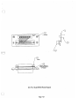
Build a camera output test furture. Use Figure 5-1 as
a guide. Connect wires to a male 25 pin connector.
Strip,tin, and label the wire ends. Plug the connector
into 5108 on the back panel of the SAP1626. Connect
the oscilloscope common lead to pin number 1.
Connect station 2 to BOP220 output 1
(5101).
5.4.11.1 Set all CAMERA thumbwheels to 1.
5.4.10.10
Listen on channel 2 of station 2 for the 100
Hz tone. Move station 2 to BOP220 output 2 (5102)
and listen for tone. Repeat for each output.
Touch scope probe to pin 14. Talk on station 1channel 1and verify audio. Move upper CAMERA
thumbwheel to 2 and check that audio stops.
5.4.10.11 Connect signal generator to program input
3 (5107). Set generator for 10 kHz and 4 volts AC
peak-to-peak (1.41 volts RMS).
Touch scope probe to pin 20. Talk on station 1channel 1and verify audio. Move lower CAMERA
thumbwheel to 2 and check that audio stops.
Check the AC voltage on bus wire connecting pin 15 of the thumbwheel switches for 2.0
volts AC peak-to-peak (0.70 volts RMS).
Repeat for cameras 2 - 6, pins 15-25.
5.4.10.12
5.4.10.13 Set the lower row of thumbwheels to 15.
The upper row stays at 12.
5.4.10.14
Connect station 2 to BOP220 output 1
5.4.11.2 Set all CAMERA thumbwheels to 2.
Touch scope probe to pin 14. Talk on station 1channel 1and verify audio. Move upper CAMERA
thumbwheel to 3 and check that audio stops.
(5101).
5.4.10.15 Listen on channel 2 of station 2 for the 10
KHz tone. Move station 2 to BOP220 output 2
(5102) and listen for tone. Repeat for each output.
5.4.10.16 With the tone still connected to program 3,
set the upper row of thumbwheels to 15. With the 0scilloscope, check between phis 1and 2 of all the XLR
output connectors on the BOP220 for 2.0 volts AC
peak-to-peak (0.70 volts RMS).
Connect the tone to program input 2
(J106). Set the upper row of thumbwheels to 14.
With the oscilloscope, check between pins 1and 2 of
all XLR output connectors on the BOP220 for 2.0
volts AC peak-to-peak (0.70 volts RMS).
Touch scope probe to pin 20. Talk on station 1channel 1and verify audio. Move lower CAMERA
thumbwheel to 3 and check that audio stops.
Repeat for cameras 2 - 6, pins 15-25.
5.4.113 Set all CAMERA thumbwheels to 3.
Touch scope probe to pin 14. Talk on station 1channel 1and verify audio. Move upper CAMERA
thumbwheel to 4 and check that audio stops.
5.4.10.17
5.4.10.18 Connect the tone to program input 1
(J105). Set the upper row on thumbwheels to 13.
With the oscilloscope, check between pins 1and 2 of
all XLR output connectors on the BOP220 for 2.0
volts AC peak-to-peak (0.70 volts RMS).
Touch scope probe to pin 20. Talk on station 1channel 1and verify audio. Move lower CAMERA
thumbwheel to 4 and check that audio stops.
Repeat for cameras 2 - 6, pins 15-25.
Connect station 1to channels 5 and 6 of the "TW"
power supply. Connect the "TW" power supply to
J l l l input on SAP1626.
Page 5-4
PIN
CONNECTION
COMMON
COMMON
COMMON
COMMON
COMMON
COMMON
COMMON
COMMON
COMMON
COMMON
COMMON
COMMON
NOT USED
CAMERA 1 CHANNEL 1
CAMERA 2 CHANNEL 1
CAMERA 3 CHANNEL 1
CAMERA 4 CHANNEL 1
CAMERA 5 CHANNEL 1
CAMERA 6 CHANNEL 1
CAMERA 1 CHANNEL 2
CAMERA 2 CHANNEL 2
CAMERA 3 CHANNEL 2
CAMERA4CHANNEL 2
CAMERA 5 CHANNEL 2
CAMERA 6 CHANNEL 2
TEST
CONNECTIONS
Figure 5-1
Camera Output Test F i u r e
Page 5-5
CAMERA OUTPUTS TEST, cont'd
5.4.11.4 Set all CAMERA thumbwheels to 4.
Touch scope probe to pin 14. Talk on station 1channel 1and verify audio. Move upper CAMERA
thumbwheel to 5 and check that audio stops.
Touch scope probe to pin 20. Talk on station 1channel 1and verify audio. Move lower CAMERA
thumbwheel to 5 and check that audio stops.
-
Repeat for cameras 2 6, pins 15-25.
5.4.113 Set all CAMERA thumbwheels to 5.
Touch scope probe to pin 14. Talk on station 1channel 1and verify audio. Move upper CAMERA
thumbwheel to 6 and check that audio stops.
Touch scope probe to pin 20. Talk on station 1channel 1and verify audio. Move lower CAMERA
thumbwheel to 6 and check that audio stops.
Repeat for cameras 2 - 6, pins 15-25.
5.4.11.6 Set all CAMERA thumbwheels to 6.
Touch scope probe to pin 14. Talk on station 1channel 1and verify audio. Move upper CAMERA
thumbwheel to 7 and check that audio stops.
5.4.11.8 Set all CAMERA thumbwheels to 8.
Touch scope probe to pin 14. Talk on station 1channel 1and verify audio. Move upper CAMERA
thumbwheel to 9 and check that audio stops.
Touch scope probe to pin 20. Talk on station 1channel 1and verify audio. Move lower CAMERA
thumbwheel to 9 and check that audio stops.
5.4.11.9 Set all CAMERA thumbwheels to 9.
Touch scope probe to pin 14. Talk on station 1channel 1and verify audio. Move upper CAMERA
thumbwheel to 10 and check that audio stops.
Touch scope probe to pin 20. Talk on station 1channel 1and verify audio. Move lower CAMERA
thumbwheel to 10 and check that audio stops.
5.4.11.10 Set all CAMERA thumbwheels to 10.
Touch scope probe to pin 14. Talk on station 1channel 1and verify audio. Move upper CAMERA
thumbwheel to 11and check that audio stops.
Touch scope probe to pin 20. Talk on station 1channel 1and verify audio. Move lower CAMERA
thumbwheel to 11and check that audio stops.
5.4.11.11 Set all CAMERA thumbwheels to 11.
Touch scope probe to pin 20. Talk on station 1channel 1and verify audio. Move lower CAMERA
thumbwheel to 7 and check that audio stops.
Touch scope probe to pin 14. Talk on station 1channel 1and verify audio. Move upper CAMERA
thumbwheel to 12 and check that audio stops.
Repeat for cameras 2 - 6, pins 15-25.
Touch scope probe to pin 20. Talk on station 1channel 1and verify audio. Move lower CAMERA
thumbwheel to 12 and check that audio stops.
5.4.11.7 Set all CAMERA thumbwheels to 7.
5.4.11.12 Set all CAMERA thumbwheels to 12.
Touch scope probe to pin 14. Talk on station 1channel 1and verify audio. Move upper CAMERA
thumbwheel to 8 and check that audio stops.
Touch scope probe to pin 20. Talk on station 1channel 1and verify audio. Move lower CAMERA
thumbwheel to 8 and check that audio stops.
Touch scope probe to pin 14. Talk on station 1channel 1and verify audio. Move upper CAMERA
thumbwheel to 13 and check that audio stops.
Touch scope probe to pin 20. Talk on station 1channel 1and verify audio. Move lower CAMERA
thumbwheel to 13 and check that audio stops.
END OF TEST
Page 5-6
'.-1
53
TROUBLESHOOTING
SYMPTOM
CHECK:
No program sound
Program input connections; Program input; Volume pot (optional)
Distorted sound
Input connections; Supply voltages.
Hum at user stations
Input/Ground connections;
Headset left lying on top of equipment with microphone on.
No sound at user stations
Power supply voltages; Connections: for shorts, for opens in cabling.
Page 5-7
SECTION 6: LISTS OF REPLACEABLE PARTS
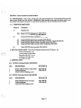
6.1 INTRODUCTION This section contains parts lists and instructions for ordering replacement parts. The
parts lists are divided into four sections: shipping list, final assembly, back panel, and printed circuit board.
Immediately following the description of a part is the manufacturer and the manufacturer's part number.
6.1.1 DIVISION OF PARTS LISTS
Section #
Description
6.3
Shipping Lists
6.31
6.32
6.4
Model SAP1626 Shipping List, 9000-3949-00
Model BOP220 Shipping List, 9000-4689-00
Model SAP1626 Final Assembly, 9010-3949-00
6.5
6.6
6.7
6.8
6.9
Model SAP1626 Back Panel Assembly, 9020-3866-00
Model SAP1626 Printed Circuit Assembly, Connector Adapter, 9030-4025-00
Model SAP1626 Printed Circuit Assembly, Switch, 9030-3871-00
Model SAP1626 Triple Current Limiter, (Optional), 9030-1602-00
Model BOP220 Final Assembly, 9010-4689-00
6.2 HOW TO OBTAIN PARTS Parts may be obtained directly from RTS Systems, Inc.:
Telex Communications,Inc.
12000Portland Avenue South,
Burnsville, MN 55337 U.S.A.
Telephone: (877) 863-4169
Fax: (800) 323-0498
6 3 SHIPPING LISTS
a
63.1 SAP1626 (Ordering Number 9000-3949-00)
RTS PART #
QTJ
DESCRIPTION
1
1
1
Model SAP1626Source Assign Panel
Technical Manual
Model SAP1626 Shipping carton
'
9010-3949-00
9300-4200-00
6 3 2 BOP220 (Ordering Number 9000-4689-00)
1
1
1
DESCRIPTION
RTS PART #
Model BOP220 Break Out Panel
Technical Manual
Model BOP220 Shipping carton
9010-4689-00
9300-4200-00
Page 6-1
6.4 FINAL ASSEMBLY, SAP1626 9010-3949-00
REF#
_OTY
DESCRIPTION
RTS PART #
Screw, 4-40 x 1/4", pan head, phiips, black
Switch Assembly, 6 position thumbwheel, Unimax SR55CX6
Switch Assembly, 5 position thumbwheel, Unimax SR55CX5
Cable Assembly, camera connector
Back panel assembly
Printed Circuit Assembly
Spacer strip, PCB, SW
Chassis Assembly, SAP1626
Covers, top/bottom
Bracket
Screw, 8-32 X 318, pan head, phillips
Washer, lock, #8
1008-4007-00
1907-0005-00
1907-0006-00
9020-5317-00
9020-3866-00
9030-3871-00
9040-4232-00
9090-3959-00
9100-3230-00
9110-3867-00
1008-8022-00
1006-0027-00
6 5 BACK PANEL, SAP1626 9020-3866-00
REF#
1
2
3
4
5
QTJ
DESCRIPTION
RTS PART @
1
Back panel, SAP1626, per finishing detail FD3866
Cable mounting cradle Panduit PIN TMlS4
Screw, jack, hex, 9/16", Electrical Hardware P/N RA-47-50-7
Connector Stabilization Plate
Nut, hex, kep 4-40
9080-3866-00
1005-0046-00
1005-0092-00
9100-1942-00
1007-0001-00
Screw, 4-40 X 318, pan head, phillips, cad plated
Screw, 4-40 x 318" flat head, phillips
Thumbscrew, 6-32x 112"Smith PIN 2366
Screw, 4-40 x 112" pan head, phillips
Screw, 6-32 x 3/8, b i d head, phillips, cadmium
Cable assembly, 50 conductor
Cable assembly, 50 conductor
Cable assembly
Cable assembly
Cable assembly
Cable assembly
Cable assembly
Cable assembly
Cable assembly
SAP1626 Connector Adaptor, PCA
Spacer hex 6-32 x 11/2', Smith P/N 8429
Connector, round, 3-pin, female Cannon XLR 3-31
Connector, round, 4-pin, female Cannon AXR 4-31
Washer, lock internal tooth, # 6
Shrink Sleeving, 3/16" blk
1008-4035-00
1008-4037-00
1008-6W2-00
1008-4025-00
1008-6013-00
9020-3950-01
9020-3950-02
9020-3952-01
9020-3952-02
9020-3952-03
9020-3953-01
9020-3953-02
9020-3953-03
9020-3953-04
9030-4025-00
1001-0006-00
2018-0003-00
2018-0001-00
1006-0006-00
1301-0005-00
2
2
1
18
Page 6-2
\.-- 1
6.6 PRINTED CIRCUIT ASSEMBLY CONNECTOR ADAPTOR, ,9030-4025-00
REF#
Q
T
J
!
DESCRIPTION
RTS PART #
1
1
Printed Circuit Board, SAP1626 PCA Connector Adapter
9040-4025-00
2
1
Jack Socket Assembly, 3M PIN 3341-12,
(This standard, prepackaged assembly consists of two jack
sockets [used here], and assorted hardware, [not used here]).
1005-0045-00
3
1
Connector, "DM,
25 pin female, Cannon PIN DB25SV
4
4
Spacer, 4-40 x 118, PCB, PEM PIN KFB3-440-4
5
1
Header, 26-pin, dual row, boxed, 3M PIN 3593-6002
6
2
Stand Off, 4-40 x 3/16", PEM PIN KFB3-440-6
6.7 PRINTED CIRCUIT,BOARD SWITCH, 9030-3871-00
REF#
<)TY
DESCRIPTION
RTS PART #
C1-10
10
Capacitor, electrolytic, aluminum, radial 10uF/50V
1513-R106-41
J1-4
4
Connector, PCB boxed header, male,
20 pin dual row (3M P/N 3592-6002)
J5
1
Connector, PCB straight header, male,
6 pin single row, Panduit PIN MHLS 100-6C
1
Connector, PCB straight boxed header, male,
26 pin dual row, 3M PIN 3593-6002
511-14
4
Connector, PCB header, male, 4 pin single row
Panduit P/N MLSS 100-4C
PC1
1
Printed circuit board
R1-3
3
Resistor, Carbon Film, 200 ohm 1/4W ~ 5 %
R4-15
12
Resistor, metal oxide, 0.1 ohm, 1/2W 2 5 %
T1
3
Transformer, audio, 600 o h 6 0 0 ohm, 200 mW,Bourns PIN LM9003 2306-0001-00
XS1-XS52
52
Connector, PCB header, 24 position dual row, female,
Aptronics P/N 929852-01-12
J8
a \
.,
1413-OR10-5E
2007-0078-00
6.8 TRIPLE CURRENT LIMITER ASSEMBLY, SAP1626 (Optional) 9030-1602-00
PC1
CRl-CR6
F1-F3
Rl,R3,R5
R2,R4,R6
U1-U3
14
16
17
18
19
20
21
22
25
RTS PART #
DESCRIPTION
REF#
1
6
3
3
3
3
3
3
3
6
6
6
6
6A/R
Printed Circuit Board, triple current limiter
Diode, rectifier,3 ampere, Motorola PIN MR502
Fuse, 3 amp slo-bloLittelfuse PIN 313003
Resistor, wire wound, 1ohm 5%, 5 W
Resistor, carbon film 2.2 kilohm 5%, 1W
Integrated Circuit, voltage regulator, LM317
Insulator, mica, TO-3, Motorola PIN B552600FOll
Heatsink, / mounting bracket,
Heatsink, TO3 type,THE 6014B
Washer, insulating, Keystone PIN 3054
Screw, 6-32 x 1/2", pan head, slotted
Nut, hex, kep 6-32
Washer, #6 flat cadmium plated
Fuse clip, P.C. Littelfuse PIN 102071
Thermal grease
9040-1600-00
1601-0502-00
2801-0018-00
1404-01RO-51
1402-2201-SF
1603-0317-OK
1306-0001-00
9180-1605-00
4502-0004-00
1006-0022-00
1008-6018-00
1007-0002-00
1006-0005-00
2802-0005-00
6.9 FINAL ASSEMBLY, BOP220 (2nd Generation) 9010-4689-00
1
2
3
4
5
6
2
6
2
20
8
9
10
11
12
13
14
RTS PART #
DESCRIPTION
REF#
1
1
1
2
2
1
8
Not Used
Spacer, hex 6-32 x 718 THD, Smith PIN 8426
Thumbscrew, 6-32 x 112, Smith PIN 2366
Screw, 6-32 x 318 pan head phillips
Connector, 50-pin male microribbon,
TRW Cinch PIN 57-10500-27
Connector, 3-$i XLR, male, plastie, Neutrik 3MPP
Not Used
BOP220 Printed circuit board
BOP220 Front panel
BOP220 Back panel
Cover, 4012 & BOP220 / Rack Ear3
Side rail 4012
Bracket
Screw, 8-32 x 318 pan head phillips
Note:
The REF#, above, is the Reference Designator when given as a letter/number combination.
When given as a number only, this number correlates with the circled numbers on assembly drawings.
Page 6-4
A.2 Detailed Information
SECTION A: APPENDIX A
A.l General Information and Definitions
Normally the SAP1626 serves the dual purpose of signal and DC power distribution. In general, the
SAP1626 connects between the system channels or
buses and TW User Stations or strings of TW User
Stations (normally to the TW User Stations through
the BOP220). The system channels or buses are usually established by TW Power Supplies. Often these
buses are also connected to an 800 series balanced
intercom system through a System Interconnect (e.g.
Models 862,860).
Connect each of the four-pin INTERCOM CHANNEL INTERCONNECT Connectors on the SAP1626
rear panel to a TW three channel Power Supply (for
wet channel operation) or a termination plug (dry
channel operation). Connect the two frfty pin connectors to a Model BOP220 or equivalent using two
50-conductor ribbon cables.
Regarding the four-pin cable assemblies: One to four
cable assemblies required for connecting one to four
TW Power Supplies respectively. There are two types
of cable assemblies: one for the Early* PS30/PS60
power supplies and one for all the rest of the TW
Power Supplies:
A "wet" channel contains 32 volts DC and two-way
intercom audio.
The Late* PS30
The PS31
The PS50
The Late* PS60
A "dry" channel contains, two-way intercom audio
only.
A TW User Station must be connected so that its
channel 1is connected to a "wet" channel; its channel
2 may be connected to either a "wet" or "dry" channel.
(Exception: Local powered TW User Stations can be
arbitrarily connected to wet or dry channels).
Figure A-1 below shows early PS30/60 cable assembly
wiriig.
The top row of switches on a SAP1626 connect to the
channel one inputs of TW User Stations and should
always be dialed to a "wet" channel. (Exception: If all
stations are local powered, dial up can be arbitrary).
Figure 2-1 above shows the connection of four system-standard type Power Supplies (PS31, PS50, Late
PS30/PS60) to the SAP1626.
.,.
The bottom row of switches can be arbitrarily dialed
to any channel. Dialing to channel zero connects the
TW User Station/StationsYchannel two connection to
ground (dead channel).
The SAP1626 Power Supply Inputs can be connected
to one, two, three, or four three channel power supplies to get three, six, nine, or twelve "wet" channels,
respectively.
Figure A-2 below shows the connection of four Early
PS30/PS60 Power Supplies to the SAP1626.
Figure 2-2 above shows the system-standard PS31,
PS50, and Late PS30/60, Power Supplies cable assembly wiriig.
14.22Special Note on Models PS30 and PS60
All Model PS30/PS60's have six "internal" or "local"
channels (versus "system"channels or "buses"):
three powered and three unpowered or "dry",
available on four 4- pin output connectors
(5101, J102,J106,J107).
On the SAP1626, Channels 13, 14, and 15 are always
dry, and, in general, the top row of switches should
not be left on these channels, because an unpowered
TW User Station could absorb some of the Intercom
or Program Audio that may appear on these channels.
The powered channels are on channels 1,3,5;
the dry channels, 2,4,6.
"
Ear!y y d late production PS30/PS60 power supplies differ m their connections, explained below.
Page A-1
Early versus Late PS30/PS60 Power Supplies
Earlv Production PS 30lPS60 Power Supplies
On units produced before mid 1983, the output connectors are connected as follows:
Output
Conn.
Internal/
Local
Channels
PS30 #1
Normally
Wired to
System
Channels
PS30 #2
Normally
Wired to
System
Channels
PS30 #3
Normally
Wired to
System
Channels
PS30 #4
Normally
Wired to
System
Channels
Late Production PS 30/PS60 Power Supplies
On units produced after mid 1983, the output connectors are connected as follows:
Output
Conn.
Internall
Local
Channels
JlOl
5102
1,233
4,5,6
PS30 #1
Normally
Wired to
System
Channels
PS30 #2
Normally
Wired to
System
Channels
PS30 #3
Normally
Wied to
System
Channels
PS30 #4
Normally
Wired to
System
Channels
PS31#3
Normally
Wired to
System
Channels
PS31#4
Normally
Wired to
System
Channels
PS31 Power Supply Connections
Output
Conn.
Internal/
Local
Channels
JlOl
5102
1,2,3
4,5,6
PS31#1
Normally
Wired to
System
Channels
PS31#2
Normally
Wired to
System
Channels
N = No Connection :* = Intercom audio onlv
Page A-2
A4F
CA'BLE
CONNECTOR
A4M
CABLE
CONNECTOR
SHIELD
>
1
1
2
2
3
3
4
TO
EARLY
PS30/PS60
POWER
SUPPLY
u
A4F
CABLE
CONNECTOR
>
-
4
.
I
u
SHIELD
1
2
>
4
Figure A-1
Early Models PS30/PS60 TO SAP1626 Cable Assembly
Page A-3
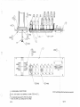
TO
SAP 1626
TW POWER SUPPLIES
CHANNEL
(1,3,5)
OUTPUTS
SAP 1626
4
/
I
BOP220
1
E] ~ 1 1 (1.-2-31
J l O l (1-101
CHANNEL
[i
50
I
I
[a
J122
4
J l 13 (7-8-91
'
VIE306
J114 (10-1 1-12)
J105 J106 J107
PROGRAM INPUTS
G- MALE CONNECTOR
0-FEMALE CONNECTOR
Figure A-2
Connection of Early Models PS30/PS60 TO SAP1626
Page A-4
B 2 Detailed Information
SECTION B: APPENDIX B
I
B.l General Information and Definitions
Normally the SAP1626 serves the dual purpose of signal and DC power distribution. In general, the
SAP1626 connects between the system channels or
buses and TW User Stations or strings of TW User
Stations (normally to the TW User Stations through
the BOP220). The system channels or buses are usually established by TW Power Supplies. Often these
buses are also connected to an 800 series balanced
intercom system through a System Interconnect (e.g.
Models 862,860).
Because the SAP1626 has no current limiters, the
PS50 and PS60 power supplies may shorten the life of
the thumbwheel switches. Current limiters may be
added to the PS50 and PS60 power supplies to
lengthen switch life.
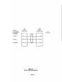
Figure B-1 shows the connection of the triple current
limiter in the SAP1626.
The triple current limiter schematic diagram, SD1598,
is on page 7-17, in the next section.
The triple current limiter assembly diagram, AS1601,
is on page 7-19, in the next section.
A "wet" channel contains 32 volts DC and two-way
intercom audio.
A "dry" channel contains two-way intercom audio
only.
F3
A TW User Station must be connected so that its
channel 1 is connected to a "wet" channel; its channel
2 may be connected to either a "wet" or "dry" channel.
(Exception: Local powered TW User Stations can be
arbitrarily connected to wet or dry channels).
The top row of switches on a SAP1626 connect to the
channel one inputs of TW User Stations and should
always be dialed to a "wet" channel. (Exception: If all
stations are local powered, dial up can be arbitrary).
The bottom row of switches can be arbitrarily dialed
to any channel. Dialing to channel zero connects the
TW User Station/Stations' channel two connection to
ground (dead channel).
The SAP1626 Power Supply Inputs can be connected
to one, two, three, or four three channel power supplies to get three, six, nine, or twelve "wet" channels,
respectively.
On the SAP1626, Channels 13, 14, and 15 are always
dry, and, in general, the top row of switches should
not be left on these channels, because an unpowered
TW User Station could absorb some of the Intercom
or Program Audio that may appear on these channels.
Page B-1
f
0
a
1
7
2
-
.
I
3
a
a
4
5
T
6
THUMBWHEEL
SWITCH
{
BUSES
-
-
7
--
7
8
-
7
9
--
-
10
H
12
T
13
I
14
I
15
\
POWER SUPPLY
INPUT 1
A1
1
)2
)3
)4
-
E15
El7
A2
POWER SUPPLY
INPUT 2
TRIPLE CURRENT
LIMITER
P.C BOARD
(AS1601,SD1598)
E20
CH 1,2,3
E22
El9
El8
-
1
2
3
>4
>
>
E15
El7
POWER SUPPLY
INPUT 3
TRIPLE CURRENT
LIMITER
P.C. BOARD
(AS1601.SDi598)
CH 4,5,6
El9
E26
L
A3
I
El8
E20
E22
E26
>
1
2
:
3
4
-
El7
POWER SUPPLY
INPUT 4
TRIPLE CURRENT
LIMITER
P.C. BOARD
(AS1601,SD1598)
CH 7.8.9
El9
El8
'
E20
E22
A4
1
>2
>3
4
E15
.
>
TRIPLE CURRENT
LIMITER
P.C. BOARD
(AS1601,SD1598)
CH 10,11,12
E26
El9
E 18
E20
E22 .
E26
I
Figure B-1
Triple Current ~i/niterInstallation Into the SAP1626
Page B-2
I
..\
.
.
1
SECTION 7: DIAGRAMS
Document
Number
Page
Number
Title
.
Final Assembly (Assembly of Assemblies)
SD
AS
ID
3949
3949
3949
WD 3949
Schematic Diagram. Source Assign Panel. Model SAP1626...............................................7 - 3
Assembly Diagram, Final, Source Assign Panel. Model SAP1626........................................7-5
Installation Diagram. Source Assign Panel. Model SAP1626
7-7
Wiring Diagram. Source Assign Panel. Model SAP1626 ....................................................... 7-9
................................................
Back Panel Assembly
AS
AS
3866
4025
Assembly Diagram. Back Panel, Source Assign Panel. Model SAP1626.............................7-11
Assembly Diagram. Connector Adapter PCA. Source Assign Panel. Model SAP1626.....7-13
Switch Motherboard Assembly
AS
SD
3871
3871
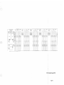
Assembly Diagram. Switch Motherboard PCA. Source Assign Panel. SAP1626 ..............7-15
Schematic Diagram. Switch Motherboard PCA. Source Assign Panel. SAP1626 .............7-17
Triple Current Limiter Assembly (Optional)
SD
AS
1598
1601
Schematic Diagram. Triple Current Limiter. Source Assign Panel ......................................7-19
Assembly Diagram. Triple Current Limiter. Source Assign Panel .......................................7-21
SD
ID
AS
1773
1634
4689
Schematic Diagram. Break-Out Panel. Model BOP220
Installation Diagram. BOPZU)
Assembly Diagram, Final, Break-Out Panel. Model BOP220
......................................................... 7-23
................................................................................................... 7-25
...............................................7-27
Page 7-1
JIW
7/03
EXTERNAL
SWITCH WTPUrS
WUMBWIIEEL
11-20
CAMERA THUMBWHEEL
SWITCH OUTPUTS I-G
TO VIE -3OS UN1TS
~
1
/
~
-
1
e
~
~
n
~
~
~
-
~
f
i
l
r
f
i
l
~
n
l
~
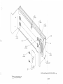
AS 3949 / Assembly Diagram, Final, Source Assign Panel, Model
Page 7-3
~
1
~
~
l
~
l
4 REQD
REQD
WD 3949 / Wiring Diagram, Source Assign Panel, Model SAP1626
I . SEE WIRING DIAGRAM WD3949 FOR REF.
NOTES:
Page 7-5
2 . WEIGHT : 10.0 IbS (4.5 K g ) .
I. ALL DIMENSIONS : INCHES (mm ).
NOTES :
AS 4025 / Assembly Diagram, Connector Adapter PCA, Source Assign Panel, Model SAP1626
Page 7-7
BACK
PANEL
J107
J106
J105
--
4
;SHT2
I
AS3950-I
A
HT 2
AS3871 SAP1626 PCB
FRONT PANEL
I
I
SD 3871 / Schematic Diagram, Switch Motherboard PCA, Source Assign Panel, SAP1626
I. SEE FINAL ASSEMBLY,AS3949 FOR REF
NOTES:
Page 7-9A
BACK
PANEL
AS3871 SAP 1626 P C B
FRONT
PANEL
SD 3871 / Schematic Diagram, Switch Motherboard PCA, Source Assign Panel, SAP1626
Page 7-9B
3 REQD
3. S.€E WIRING DIAGRAM WD3949 FOR REF.
APpL V SHRINK TUBING TO AU TERMNALS, A 5 SNOWnl-
(96"
014 X @
L)
.
%4 REQD
AS 1601 / Assembly ~iagram,Triple Current Limiter, Source Assign Panel
{/c,
TIE WIRE5 FROM CABLE ,455 Y ~ TEMS
, I
N
AROUND
CONN.5 AS S#Ovt/N. ALSO BUNDLE 4ND VE AS REQD
NOTES:
Page 7-11
(4 PLACES)
1
( 2 PLACES)
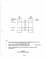
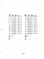
SD 1773 / Model BOP220 Pinout Diagram
Page 7-13
I
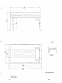
AS 4689 / Assembly ~ i a ~ r aFinal,
b , Break-Out Panel, Model BOP220
3. A L L TRANSFORMERS ARE 600 : 6 0 0 , L M 9 0 0 3 .
2, ALL CAPACITOR VALUES ARE i o 4 f / 5 0 VOLTS.
I. ALL RESISTORS ARE CARBON FILM, 1/4
W ? 5%.
VALUES ARE IN OHMS.
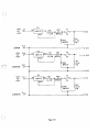
Page 7-17
I
U1
+36V
El5
TO
0
IN LM317K
+40V
-OUT
ADJ
-
F1
R1
CR 1
la,5W
MR502
M
-
3A
R2
2.2K
1W
21;CR 2
MR502
-
I
I
E l9
COM M ON
0
El6
TO
+40V
0
J
0 E24
T
U2
+36V
IN
LM317K
OUT
F2
R3
/VVG
CR 3
la15W
MR502
D l = -
-
3A
ADJ
'
E21
0
R4
2.2K
1W
El7
0
MR502
41
T
U3
+36V
TO
+40V
0 E20
v
2i CR 4
COMMON
O El8
I N LM317K .OUT
R5
ln,5W
CR 5
;
MI3502
ADJ
F3
a = 0
0 ~2'2
a
7
3A
25 CR6
MR502
R6
2.2K
1W
a
T
1
E23
COM M ON
0
Page 7-19
0 E26
Page 7-21
Page 7-23
AS 4689 / Assembly Diagram, Final, Break-Out Panel, Model BOP220
/. FOR PART NO'S AND DESCR/PT/ONS SEE
SEPARATE PARTS LIST 90/0-4689-00
NOTES
,.
I
I
Page 7-27