1
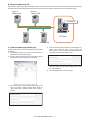
E-MANUAL
22-2
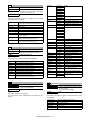
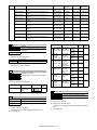
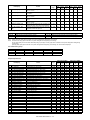
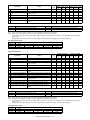
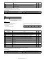
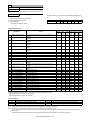
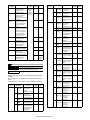
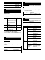
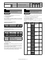
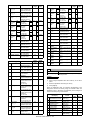
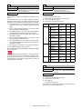
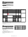
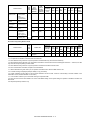
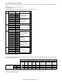
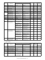
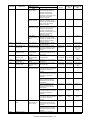
Purpose
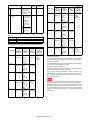
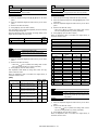
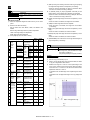
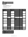
Adjustment/Setting/Operation data check
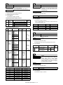
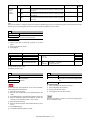
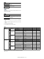
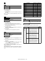
Function (Purpose) Used to check the total number of misfeed
and troubles. (When the number of total
jam is considerably great, it is judged as
necessary for repair.)
Section
The paper jam, trouble counter value is displayed.
Machine JAM counter
RSPF JAM counter
Trouble counter
22-3
Purpose
Adjustment/Setting/Operation data check
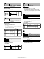
Function (Purpose) Used to check misfeed positions and the
misfeed count of each position.
* Presumption of the faulty point by this
data is possible.
Section
Operation/Procedure
The paper jam and misfeed history is displayed from the latest one
up to 50 items. (The old ones are deleted sequentially.)
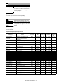
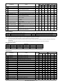
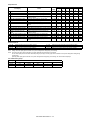
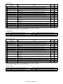
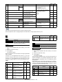
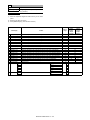
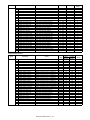
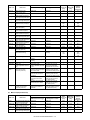
22-4
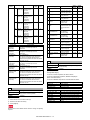
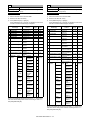
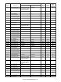
Adjustment/Setting/Operation data check
Purpose
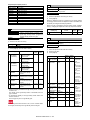
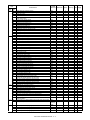
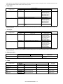
26cpm/36cpm/31cpm(A) machine
S/N
Operation/Procedure
MACHINE JAM
RSPF JAM
TROUBLE
WATER MARK
ESCP
PDL
PCI
Operation manual (HDD storage)
(except 20cpm machine)
Watermark (HDD storage)
ESCP font ROM
PDL font ROM
PCI
UICONTENTS
ICU (MAIN)
ICU (BOOT)
ICU (SUB)
LANGUAGE
GRAPHIC
PCL (MAIN)
PCL (PROFILE)
PCU
SCU
FAX1 (MAIN)
DESK
LCC
FINISHER
PUNCH
NIC
POWER-CON
E-MANUAL
WATER MARK
ESCP
ACRE (MAIN)
ACRE (DATA)
PCI
Serial No. (The codes for November and December are
"X" and "Y" respectively.)
Content data for display
ICU (Main section)
ICU (Boot section)
ICU (Sub section) (ARM9)
Language support data version
Graphic data for LCD
PCL (Main section)
PCL (Color profile)
PCU
SCU
FAX 1-Line (Main section)
Desk unit
LCC
Finisher
Punch module
NIC
Power controller
Operation manual (HDD storage)
Watermark (HDD storage)
ESCP font ROM
Enhanced compression kit (Main section)
Enhanced compression kit (Data section)
PCI
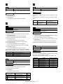
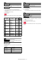
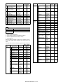
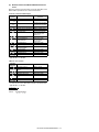
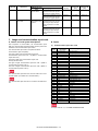
Function (Purpose) Used to check the trouble (self diag) history.
Section
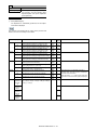
22-6
Operation/Procedure
Purpose
The trouble history is displayed from the latest one up to 30 items.
(The old ones are deleted sequentially.)
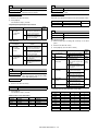
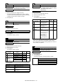
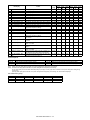
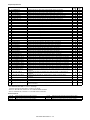
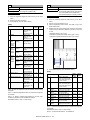
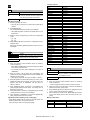
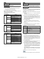
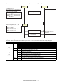
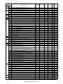
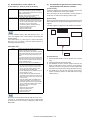
Function (Purpose) Used to output the setting/adjustment data
(simulation, FAX soft switch, counter), the
firmware version, and the counter list.
Adjustment/Setting/Operation data check
Section
22-5
Operation/Procedure
Purpose
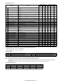
Others
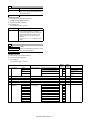
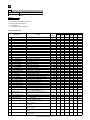
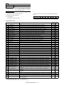
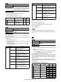
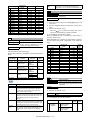
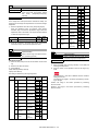
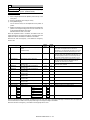
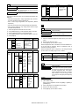
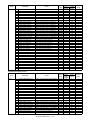
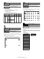
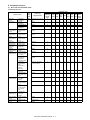
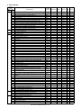
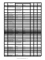
Function (Purpose) Used to check the ROM version of each
unit (section).
* When installing or servicing, this simulation is executed to print
the adjustment data and set data for use in the next servicing.
(Memory trouble, PWB replacement, etc.)
Section
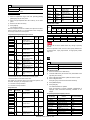
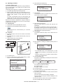
1)
Firmware
Select the print list mode with 10-key.
Operation/Procedure
Item/Display
The ROM version of the installed unit in each section is displayed.
When there is any trouble in the software, use this simulation to
check the ROM version, and upgrade the version if necessary.
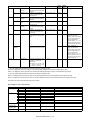
A
DATA PATTERN
2
3
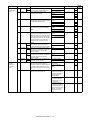
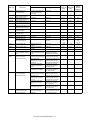
18cpm/20cpm/23cpm/31cpm(G) machine
S/N
ICU (MAIN)
ICU (BOOT)
ICU (SUB)
LANGUAGE
GRAPHIC
PCL (MAIN)
PCL (PROFILE)
PCU
SCU
FAX1 (MAIN)
DESK
FINISHER
NIC
POWER-CON
Print list
mode
1
Serial No. (The codes for November and December are
"X" and "Y" respectively.)
ICU (Main section)
ICU (Boot section)
ICU (Sub section) (ARM9)
Language support data version
Graphic data for LCD
PCL (Main section)
PCL (Color profile)
PCU
SCU
FAX 1-Line (Main section)
Desk unit
Finisher
NIC
Power controller
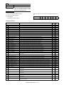
2)
Print content
Firmware version,
counter data, etc.
SIM50-24 data
Data related to the process control
Press [EXECUTE] key to start printing the list selected in step
1).
MX-3610N SIMULATION 5 – 23
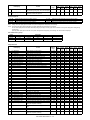
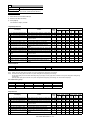
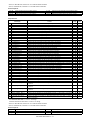
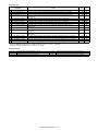
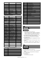
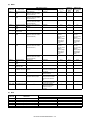
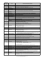
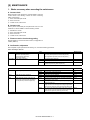
22-8
MACHINE
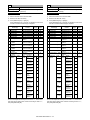
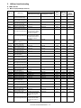
Purpose
Adjustment/Setting/Operation data check
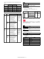
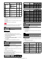
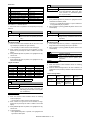
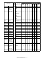
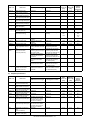
Function (Purpose) Used to check the number of operations
(counter value) of the finisher, the RSPF,
and the scan (reading) unit.
Section
Operation/Procedure
SPF
The counter values of the finisher, the RSPF, and the scanner
related counters are displayed.
SPF
SCAN
STAPLER
PUNCHER
STAMP
COVER
HP_ON
OC LAMP TIME
SADDLE STAPLER
SADDLE V FOLD
Document feed quantity
(The number of sheets of discharged documents)
Number of times of scan
Staple counter
Puncher counter
Stamp counter
Document cover open/close counter
Number of scanner HP detection
Total lighting time of the scanner lamp
(* hour * minutes)
Saddle staple counter
(26cpm/36cpm/31cpm(A) machine only)
Saddle finisher V fold counter
(26cpm/36cpm/31cpm(A) machine only)
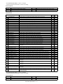
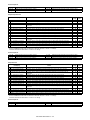
22-9
Adjustment/Setting/Operation data check
Purpose
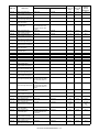
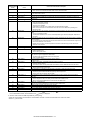
Function (Purpose) Used to check the number of use (print
quantity) of each paper feed section.
Paper feed, ADU, LCC
Section
Operation/Procedure
The counter values related to paper feed are displayed.
TRAY1
TRAY2
TRAY3
TRAY4
MFT TOTAL
MFT HEAVY
MFT OHP
MFT ENV
ADU
LCC
Paper feed counter (Paper feed tray 1)
Paper feed counter (Paper feed tray 2)
Paper feed counter (Paper feed tray 3)
Paper feed counter (Paper feed tray 4)
Manual paper feed counter (Total)
Manual paper feed counter (Heavy paper)
Manual paper feed counter (OHP)
Manual paper feed counter (Envelope)
ADU paper transport counter (Paper reverse section)
Side LCC paper feed counter (LCC)
(26cpm/36cpm/31cpm(A) machine only)
STAMP
DESK
LCC
PUNCHER
FINISHER
FAX1
PRINTER
PS
XPS
SECURITY
AIM
SDRAM (SYS)
SDRAM (ICU)
HDD
SD
NIC
BARCODE
INTERNET-FAX
ACM(*)
EAM(*)
WEB
BROWSING
ACRE
MIRRORING
PCI
MX-1810U
MX-2010U
MX-2310U
MX-2610N
MX-3111U
MX-3110N
MX-3610N
MX-RP12
STANDARD
AR-SU1
MX-DE12
MX-DE13
MX-DE14
MX-LC11
MX-PN11A
MX-PN11B
MX-PN11C
MX-PN11D
MX-PNX5A
MX-PNX5B
MX-PNX5C
MX-PNX5D
MX-FN17
MX-FN10
MX-FX11
MX-PB14
MX-PK11
MX-PUX1
MX-FR25U
MX-FR30U
MX-FR34U
MX-AMX1
*****MB
*****MB
*****MB
*****MB
STANDARD
MX-PF10
MX-FWX1
MX-AMX2
MX-AMX3
MX-AM10
MX-EB11
MX-EB12
NOTE
CONNECT
Main unit
Reversing single pass feeder
Finish stamp
Stand/1x500 sheet paper drawer
Stand/2x500 sheet paper drawer
Stand/3x500 sheet paper drawer
Large capacity tray (Side LCC)
Punch unit
Inner finisher
Saddle stitch finisher (1K)
Facsimile expansion kit
Printer expansion kit (PCL)
PS expansion kit
XPS expansion kit
Data security kit (commercial version)
Data security kit (commercial version)
Data security kit (commercial version)
Application integration module
SDRAM capacity
SDRAM capacity
Hard disk capacity
SD Card capacity
NIC
Bar code font
Internet Fax expansion kit
Application communication module
External account module
Web browsing expansion kit
Enhanced compression kit (ACRE)
Mirroring kit
PCI generating unit
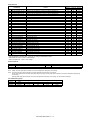
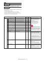
(*) Displayed only in the OSA models.
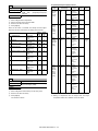
22-10
Purpose
Adjustment/Setting/Operation data check
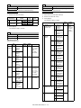
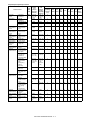
Function (Purpose) Used to check the system configuration
(option, internal hardware).
Section
Operation/Procedure
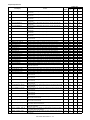
22-11
Adjustment/Setting/Operation data check
Purpose
Function (Purpose) Used to check the use frequency (send/
receive) of FAX.
(Only when FAX is installed)
Section
The system configuration is displayed.
(The model names of the installed devices and options are displayed.)
FAX
Operation/Procedure
The values of the FAX send counter and the FAX receive counter
are displayed.
FAX OUTPUT
FAX SEND
FAX RECEIVED
SEND IMAGES
SEND TIME
RECEIVED TIME
MX-3610N SIMULATION 5 – 24
FAX print quantity counter (for line 1)
FAX send counter
FAX receive counter
FAX send quantity counter (for line 1)
FAX send time
FAX receive time
22-12
Purpose
Adjustment/Setting/Operation data check
Function (Purpose) Used to check the RSPF misfeed positions
and the number of misfeed at each position. (When the number of misfeed is considerably great, it can be judged as
necessary for repair.)
Section
RSPF
Operation/Procedure
The paper jam and misfeed history is displayed from the latest one
up to 50 items. (The old ones are deleted sequentially.)
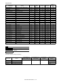
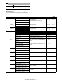
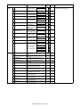
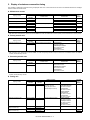
22-13
Purpose
Adjustment/Setting/Operation data check
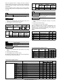
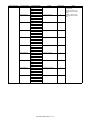
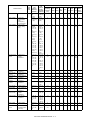
Function (Purpose) Used to check the operating time of the
process section (OPC drum, DV unit, toner
cartridge) and the fusing unit
Section
Process
Operation/Procedure
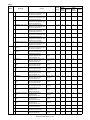
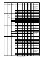
The number of prints and the number of rotations in the process
section are displayed.
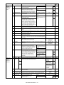
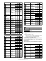
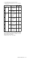
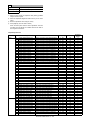
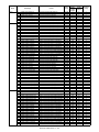
18cpm/20cpm/23cpm/26cpm/31cpm machine
Item/Display
MAINTENANCE ALL
MAINTENANCE COL
FUSING BELT
HEAT ROLLER
FUSING ROLLER
PRESSURE ROLLER
SEPARATE PAWL
SEPARATE PLATE
CLEANING ROLLER
TC1 BELT
TRANSFER BLADE
PTC
TC2 BELT
PS PAPER
OZONE FILTER
DEVE CTRG (K)
DEVE CTRG (C)
DEVE CTRG (M)
DEVE CTRG (Y)
DRUM CTRG (K)
DRUM CTRG (C)
DRUM CTRG (M)
DRUM CTRG (Y)
MAIN CHARGER (K)
MAIN CHARGER (C)
MAIN CHARGER (M)
MAIN CHARGER (Y)
DRUM BLADE (K)
DRUM BLADE (C)
DRUM BLADE (M)
DRUM BLADE (Y)
TONER CTRG (K)
TONER CTRG (C)
TONER CTRG (M)
TONER CTRG (Y)
Content
Maintenance counter (Total) (Counter)
Maintenance counter (Color)
Fusing belt (23cpm/26cpm/31cpm
machine only)
Heat roller (20cpm model)
Fusing roller
Fusing pressure roller
Fusing separation pawl
Fusing separation plate
Fusing cleaning roller
Primary transfer belt
Transfer cleaning blade
PTC
Secondary transfer belt
Paper dust cleaner
Ozone filter
DV unit (K)
DV unit (C)
DV unit (M)
DV unit (Y)
OPC drum unit (K)
OPC drum unit (C)
OPC drum unit (M)
OPC drum unit (Y)
Main charger (K)
Main charger (C)
Main charger (M)
Main charger (Y)
OPC drum cleaning blade K
OPC drum cleaning blade C
OPC drum cleaning blade M
OPC drum cleaning blade Y
Toner cartridge (K)
Toner cartridge (C)
Toner cartridge (M)
Toner cartridge (Y)
Print counter
RPM
Number of
use days
Life meter
Max. 8
Max. 8
Not displayed
Not displayed
0 - 999
0 - 999
0 - 100 (%)
0 - 100 (%)
Number of
remaining
days
0 - 365
0 - 365
Max. 8
Max. 8
0 - 999
0 - 100 (%)
0 - 365
Max. 8
Max. 8
Max. 8
Max. 8
Max. 8
Max. 8
Max. 8
Max. 8
Max. 8
Max. 8
Max. 8
Max. 8
Max. 8
Max. 8
Max. 8
Max. 8
Max. 8
Max. 8
Max. 8
Max. 8
Max. 8
Max. 8
Max. 8
Max. 8
Max. 8
Max. 8
Max. 8
Max. 8
Max. 8
Max. 8
Max. 8
Max. 8
Max. 8
Max. 8
Max. 8
Max. 8
Max. 8
Max. 8
Max. 8
Max. 8
Max. 8
Max. 8
Not displayed
Not displayed
Max. 8
Max. 8
Max. 8
Max. 8
Max. 8
Max. 8
Max. 8
Max. 8
Max. 8
Max. 8
Max. 8
Max. 8
Max. 8
Max. 8
Max. 8
Max. 8
Max. 8
Max. 8
Max. 8
Max. 8
0 - 999
0 - 999
0 - 999
0 - 999
0 - 999
0 - 999
0 - 999
0 - 999
0 - 999
0 - 999
0 - 999
0 - 999
0 - 999
0 - 999
0 - 999
0 - 999
0 - 999
0 - 999
0 - 999
0 - 999
0 - 999
0 - 999
0 - 999
0 - 999
0 - 999
0 - 999
0 - 999
0 - 999
0 - 999
0 - 999
0 - 999
0 - 999
0 - 100 (%)
0 - 100 (%)
0 - 100 (%)
0 - 100 (%)
0 - 100 (%)
0 - 100 (%)
0 - 100 (%)
0 - 100 (%)
0 - 100 (%)
0 - 100 (%)
0 - 100 (%)
0 - 100 (%)
0 - 100 (%)
0 - 100 (%)
0 - 100 (%)
0 - 100 (%)
0 - 100 (%)
0 - 100 (%)
0 - 100 (%)
0 - 100 (%)
0 - 100 (%)
0 - 100 (%)
0 - 100 (%)
0 - 100 (%)
0 - 100 (%)
0 - 100 (%)
0 - 100 (%)
0 - 100 (%)
0 - 100 (%)
0 - 100 (%)
0 - 100 (%)
0 - 100 (%)
0 - 365
0 - 365
0 - 365
0 - 365
0 - 365
0 - 365
0 - 365
0 - 365
0 - 365
0 - 365
0 - 365
0 - 365
0 - 365
0 - 365
0 - 365
0 - 365
0 - 365
0 - 365
0 - 365
0 - 365
0 - 365
0 - 365
0 - 365
0 - 365
0 - 365
0 - 365
0 - 365
0 - 365
Not displayed
Not displayed
Not displayed
Not displayed
MX-3610N SIMULATION 5 – 25
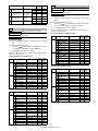
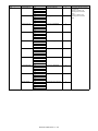
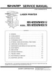
36cpm machine
Item/Display
MAINTENANCE ALL
MAINTENANCE COL
FUSING BELT
FUSING ROLLER
PRESSURE ROLLER
SEPARATE PAWL
SEPARATE PLATE
FUSING WEB UNIT
FUSING WEB SEND
TC1 BELT
TRANSFER BLADE
PTC
TC2 BELT
PS PAPER
OZONE FILTER
DEVE CTRG (K)
DEVE CTRG (C)
DEVE CTRG (M)
DEVE CTRG (Y)
DRUM CTRG (K)
DRUM CTRG (C)
DRUM CTRG (M)
DRUM CTRG (Y)
MAIN CHARGER (K)
MAIN CHARGER (C)
MAIN CHARGER (M)
MAIN CHARGER (Y)
DRUM BLADE (K)
DRUM BLADE (C)
DRUM BLADE (M)
DRUM BLADE (Y)
TONER CTRG (K)
TONER CTRG (C)
TONER CTRG (M)
TONER CTRG (Y)
Content
Maintenance counter (Total) (Counter)
Maintenance counter (Color)
Fusing belt
Fusing roller
Fusing pressure roller
Fusing separation pawl
Fusing separation plate
Fusing web unit
Fusing web cleaning send counter
Primary transfer belt
Transfer cleaning blade
PTC
Secondary transfer belt
Paper dust cleaner
Ozone filter
DV unit (K)
DV unit (C)
DV unit (M)
DV unit (Y)
OPC drum unit (K)
OPC drum unit (C)
OPC drum unit (M)
OPC drum unit (Y)
Main charger (K)
Main charger (C)
Main charger (M)
Main charger (Y)
OPC drum cleaning blade K
OPC drum cleaning blade C
OPC drum cleaning blade M
OPC drum cleaning blade Y
Toner cartridge (K)
Toner cartridge (C)
Toner cartridge (M)
Toner cartridge (Y)
Print counter
RPM
Number of
use days
Life meter
Max. 8
Max. 8
Max. 8
Max. 8
Max. 8
Max. 8
Max. 8
Max. 8
0 - 65535
Max. 8
Max. 8
Max. 8
Max. 8
Max. 8
Max. 8
Max. 8
Max. 8
Max. 8
Max. 8
Max. 8
Max. 8
Max. 8
Max. 8
Max. 8
Max. 8
Max. 8
Max. 8
Max. 8
Max. 8
Max. 8
Max. 8
Max. 8
Max. 8
Max. 8
Max. 8
Not displayed
Not displayed
Max. 8
Max. 8
Max. 8
Max. 8
Max. 8
Not displayed
Not displayed
Max. 8
Max. 8
Max. 8
Max. 8
Not displayed
Not displayed
Max. 8
Max. 8
Max. 8
Max. 8
Max. 8
Max. 8
Max. 8
Max. 8
Max. 8
Max. 8
Max. 8
Max. 8
Max. 8
Max. 8
Max. 8
Max. 8
Max. 8
Max. 8
Max. 8
Max. 8
0 - 999
0 - 999
0 - 999
0 - 999
0 - 999
0 - 999
0 - 999
0 - 999
Not displayed
0 - 999
0 - 999
0 - 999
0 - 999
0 - 999
0 - 999
0 - 999
0 - 999
0 - 999
0 - 999
0 - 999
0 - 999
0 - 999
0 - 999
0 - 999
0 - 999
0 - 999
0 - 999
0 - 999
0 - 999
0 - 999
0 - 999
0 - 999
0 - 999
0 - 999
0 - 999
0 - 100 (%)
0 - 100 (%)
0 - 100 (%)
0 - 100 (%)
0 - 100 (%)
0 - 100 (%)
0 - 100 (%)
0 - 100 (%)
Not displayed
0 - 100 (%)
0 - 100 (%)
0 - 100 (%)
0 - 100 (%)
0 - 100 (%)
0 - 100 (%)
0 - 100 (%)
0 - 100 (%)
0 - 100 (%)
0 - 100 (%)
0 - 100 (%)
0 - 100 (%)
0 - 100 (%)
0 - 100 (%)
0 - 100 (%)
0 - 100 (%)
0 - 100 (%)
0 - 100 (%)
0 - 100 (%)
0 - 100 (%)
0 - 100 (%)
0 - 100 (%)
0 - 100 (%)
0 - 100 (%)
0 - 100 (%)
0 - 100 (%)
Number of
remaining
days
0 - 365
0 - 365
0 - 365
0 - 365
0 - 365
0 - 365
0 - 365
0 - 365
Not displayed
0 - 365
0 - 365
0 - 365
0 - 365
0 - 365
0 - 365
0 - 365
0 - 365
0 - 365
0 - 365
0 - 365
0 - 365
0 - 365
0 - 365
0 - 365
0 - 365
0 - 365
0 - 365
0 - 365
0 - 365
0 - 365
0 - 365
Not displayed
Not displayed
Not displayed
Not displayed
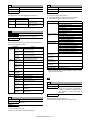
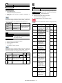
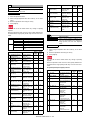
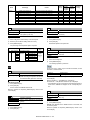
22-14
Purpose
Adjustment/Setting/Operation data check
Function (Purpose) Used to display the use status of the toner
cartridge.
Section
Process
Operation/Procedure
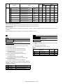
The status of the toner cartridge is displayed.
Display item
TONER (K)
TONER (C)
TONER (M)
TONER (Y)
Content
Toner cartridge use counter (K)
Toner cartridge use counter (C)
Toner cartridge use counter (M)
Toner cartridge use counter (Y)
Accumulated No. of
installed cartridges (Unit)
INSTALL
0 - 255
Accumulated No. of near
near end (Unit)
NN END
0 - 255
MX-3610N SIMULATION 5 – 26
Accumulated No. of
end (Unit)
END
0 - 255
Remaining quantity
(Unit: %)
RESIDUAL
0-25%
25-50%
50-75%
75-100%
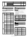
22-18
22-90
Purpose
Adjustment/Setting/Operation data check
Function (Purpose) Used to display the user data delete history.
Purpose
Section
Section
Operation/Procedure
Operation/Procedure
The date and time of the user data delete are displayed.
1)
Item name
START
END
Display item
Date
Year/month/day/hour/min.
Year/month/day/hour/min.
Content
Delete history (Date and time
of operation start)
Delete history (Date and time
of operation end)
Change the display with scroll key.
2)
Select the print target with the keys on the touch panel.
3)
Press [EXECUTE] key to start self print of the list.
All setting list (*)
Printer test page
22-19
Purpose
Adjustment/Setting/Operation data check
Function (Purpose) Used to check the values of the counters
related to the scan - image send.
Address registration
list (*)
Section
Operation/Procedure
Used to display the counter value related to the network scanner
Change the display with scroll key.
Item/Display
Network
NET SCN
scanner
ORG_B/W
NET SCN
ORG_CL
NET SCN
ORG_2CL
NET SCN
ORG_SGL
Internet
INTERNET FAX
FAX
OUTPUT
INTERNET FAX
SEND OUTPUT
INTERNET FAX
RECEIVE
INTERNET FAX
SEND
E-Mail
MAIL
COUNTER
FTP
FTP COUNTER
Other
SMB SEND
USB CNT
TRIAL
MODE_B&C
SCAN TO
HDD_B/W
SCAN TO
HDD_CL
SCAN TO
HDD_2CL
SCAN TO
HDD_SGL
Content
Network scanner document read quantity
counter (B/W scan job)
Network scanner document read quantity
counter (Color scan job)
Network scanner document read quantity
counter (2-Color scan job)
Network scanner document read quantity
counter (Single-color scan job)
Number of internet FAX output
Number of internet FAX sending page
Number of internet FAX receive
Number of internet FAX send
Number of times of E-MAIL send
Number of FTP send
Number of SMB send
Number of times of USB storage
Trial mode counter
(B/W & COLOR scan job)
SCAN TO HDD record quantity (B/W)
SCAN TO HDD record quantity
(COLOR)
SCAN TO HDD record quantity
(2-COLOR)
SCAN TO HDD record quantity
(SINGLE color)
Adjustment/Setting/Operation data check
Function (Purpose) Used to output the various set data lists.
Document filing list (*)
System setting list
Receive rejection
number table
Receive rejection/
allow address
domain table
To E-mail
Transfer table list
To administrator
Transfer list
Web setting list
Meta data set list
ALL CUSTOM SETTING LIST
PCL SYMBOL SET LIST
PCL INTERNAL FONT LIST
PCL EXTENDED FONT LIST
PS FONT LIST
PS KANJI FONT LIST (Japan)
PS EXTENDED FONT LIST
NIC PAGE
INDIVIDUAL LIST
GROUP LIST
PROGRAM LIST (Output Disable)
MEMORY BOX LIST
ALL SENDING ADDRESS LIST
DOCUMENT FILING FOLDER LIST
ADMIN. SETTINGS LIST (COPY)
ADMIN. SETTINGS LIST (PRINT)
ADMIN. SETTINGS LIST (IMAGE SEND)
ADMIN. SETTINGS LIST (DOC FILING)
ADMIN. SETTINGS LIST (SECURITY)
ADMIN. SETTINGS LIST (COMMON)
ALL ADMINISTRATOR SETTINGS LIST
ANTI JUNK FAX NUMBER LIST
ANTI JUNK MAIL/DOMAIN NAME LIST
INBOUND ROUTING LIST
DOCUMENT ADMIN LIST
WEB SETTING LIST
METADATA SET LIST
* When the data list print of system setting is inhibition in DSK
model, this setting is invalid.
23
23-2
Purpose
Adjustment/Setting/Operation data check
Function (Purpose) Used to output the trouble history list of
paper jam and misfeed. (If the number of
troubles of misfeed is considerably great,
the judgment is made that repair is
required.)
Section
Operation/Procedure
22-40
Purpose
Press [EXECUTE] key to execute print.
Error contents display
The trouble history of paper jams and misfeed is printed.
Function (Purpose) Used to display the error code list and the
contents.
Section
Operation/Procedure
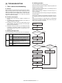
1)
Select the main error code.
The sub error code and the contents are displayed.
MX-3610N SIMULATION 5 – 27
23-80
24-2
Purpose
Purpose
Operation test/check
Function (Purpose) Used to check the operation of paper feed
and paper transport in the paper feed section and the paper transport section. Used
to output the list of the operation status of
the sensor and the detectors in the paper
feed section and the paper transport section.
Section
Operation/Procedure
1)
Select the item to be cleared with the touch panel key.
2)
Press [EXECUTE] key.
3)
Paper feed, Paper transport
Section
When [EXECUTE] key is pressed, the timing list of paper feed and
paper transport is outputted.
Used to print the operations timing list of the sensors and detectors
in the paper feed and transport section.
The timing list of paper feed and paper transport operations of the
latest job (copy or print) on the final paper is printed.
Since the paper feed and paper transport routes differ depending
on the used paper feed tray and the print operation mode, the sensor and the detectors and the operation timing also differ.
STANDARD
CURRENT (*1)
PREVIOUS (*1)
MAXIMUM (*1)
MINIMUM (*1)
Operation content (Trigger name - Detection operation
or load operation name)
Reference value (ms)
Operation timing (ms) of the latest job on the final
paper
Operation timing (ms) of the second latest job on the
final paper
Max. operation timing (ms) of all the jobs
Min. operation timing (ms) of all the jobs
*1: The value without unit on the left side of each item on the list
has no relation to the operation timing. It is not used in the market.
TRAY1
TRAY2
TRAY3
TRAY4
MFT TOTAL
MFT HEAVY
MFT OHP
MFT ENV
LCC
ADU
24-3
Data clear
Function (Purpose) Used to clear the finisher, RSPF, and the
scan (reading) unit counter.
Section
Operation/Procedure
1)
Select the item to be cleared with the touch panel key.
2)
Press [EXECUTE] key.
Press [YES] key.
The target counter is cleared.
24
SPF
24-1
Data clear
Function (Purpose) Used to clear the jam counter, and the trouble counter. (After completion of maintenance, clear the counters.)
Section
Operation/Procedure
1)
Select the item to be cleared with the touch panel key.
2)
Press [EXECUTE] key.
3)
Press [YES] key.
The target counter is cleared.
MACHINE
SPF
TROUBLE
Tray 1 paper feed counter
Tray 2 paper feed counter
Tray 3 paper feed counter
Tray 4 paper feed counter
Manual paper feed counter (Total)
Manual paper feed counter (Heavy paper)
Manual paper feed counter (OHP)
Manual paper feed counter (Envelope)
LCC paper feed counter (LCC)
ADU paper feed counter
Purpose
3)
Purpose
Press [YES] key.
The target counter is cleared.
Operation/Procedure
SECTION
Data clear
Function (Purpose) Used to clear the number of use (the number of prints) of each paper feed section.
Machine JAM counter
RSPF JAM counter
Trouble counter
SCAN
STAPLER
PUNCHER
STAMP
SADDLE STAPLER
SADDLE V FOLD
COVER
HP_ON
OC LAMP TIME
RSPF document feed counter
(No. of discharged sheets)
Scan counter
Staple counter
Puncher counter
Stamp counter
Saddle staple counter
Saddle finisher V fold counter
Document cover open/close counter
Number of scanner HP detection
Total lighting time of the scanner lamp
24-4
Purpose
Data clear
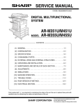
Function (Purpose) Used to clear the maintenance counter, the
printer counters of the transport unit and
the fusing unit. (After completion of maintenance, clear the counters.)
Section
Operation/Procedure
1)
Select the item to be cleared with the touch panel key.
2)
Press [EXECUTE] key.
3)
Press [YES] key.
The target counter is cleared.
MX-3610N SIMULATION 5 – 28
18cpm/20cpm/23cpm/26cpm/31cpm machine
Item/Display
Maintenance MAINTENANCE
ALL
MAINTENANCE
COL
Fusing
FUSING BELT
(23cpm/26cpm/
31cpm machine
only)
HEAT ROLLER
(20cpm model)
FUSING
ROLLER
PRESS
ROLLER
Separation
SEPARATE
PAWL
SEPARATE
PLATE
CLEAN
ROLLER
Transfer
TC1 BELT
TRANS BLADE
TC2 BELT
PTC
Drum
DRUM CTRG K
DRUM CTRG C
DRUM CTRG M
DRUM CTRG Y
Content
Maintenance counter (Total) (Counter)
Maintenance counter (Total)
(Number of use days)
Maintenance counter (Color) (Counter)
Maintenance counter (Color)
(Number of use days)
Fusing belt (Counter)
Fusing belt (Number of use days)
Fusing belt
(Accumulated number of rotations)
Heat roller (Counter)
Heat roller (Number of use days)
Heat roller
(Accumulated number of rotations)
Fusing roller (Counter)
Fusing roller (Number of use days)
Fusing roller
(Accumulated number of rotations)
Pressure roller (Counter)
Pressure roller (Number of use days)
Pressure roller
(Accumulated number of rotations)
Separation pawl (Counter)
Separation pawl (Number of use days)
Separation pawl
(Accumulated number of rotations)
Separation plate (Counter)
Separation plate (Number of use days)
Separation plate
(Accumulated number of rotations)
Cleaning roller (Counter)
Cleaning roller (Number of use days)
Cleaning roller
(Accumulated number of rotations)
Primary transfer belt (Counter)
Primary transfer belt
(Number of use days)
Primary transfer belt
(Accumulated number of rotations)
Transfer blade (Counter)
Transfer blade (Number of use days)
Transfer blade
(Accumulated number of rotations)
Secondary transfer belt (Counter)
Secondary transfer belt
(Number of use days)
Secondary transfer belt
(Accumulated number of rotations)
PTC counter (Counter)
PTC counter (Number of use days)
PTC counter
(Accumulated number of rotations)
Drum cartridge (K) (Counter)
Drum cartridge (K) (Number of use
days)
Drum cartridge (K)
(Accumulated number of rotations)
Drum cartridge (C) (Counter)
Drum cartridge (C)
(Number of use days)
Drum cartridge (C)
(Accumulated number of rotations)
Drum cartridge (M) (Counter)
Drum cartridge (M)
(Number of use days)
Drum cartridge (M)
(Accumulated number of rotations)
Drum cartridge (Y) (Counter)
Drum cartridge (Y)
(Number of use days)
Drum cartridge (Y)
(Accumulated number of rotations)
Main
charger
Item/Display
MAIN
CHARGER K
MAIN
CHARGER C
MAIN
CHARGER M
MAIN
CHARGER Y
Drum blade
DRUM BLADE
K
DRUM BLADE
C
DRUM BLADE
M
DRUM BLADE
Y
Other
PS PAPER
OZONE FILTER
Content
Main charger (K) (Counter)
Main charger (K) (Number of use days)
Main charger (K)
(Accumulated number of rotations)
Main charger (C) (Counter)
Main charger (C) (Number of use days)
Main charger (C)
(Accumulated number of rotations)
Main charger (M) (Counter)
Main charger (M) (Number of use days)
Main charger (M)
(Accumulated number of rotations)
Main charger (Y) (Counter)
Main charger (Y) (Number of use days)
Main charger (Y)
(Accumulated number of rotations)
Drum blade K (Counter)
Drum blade K (Number of use days)
Drum blade K
(Accumulated number of rotations)
Drum blade C (Counter)
Drum blade C (Number of use days)
Drum blade C
(Accumulated number of rotations)
Drum blade M (Counter)
Drum blade M (Number of use days)
Drum blade M
(Accumulated number of rotations)
Drum blade Y (Counter)
Drum blade Y (Number of use days)
Drum blade Y
(Accumulated number of rotations)
PS paper dust cleaner (Counter)
PS paper dust cleaner
(Number of use days)
Ozone filter (Counter)
Ozone filter (Number of use days)
36cpm machine
Item/Display
Maintenance MAINTENANCE
ALL
MAINTENANCE
COL
Fusing
FUSING BELT
FUSING
ROLLER
PRESS
ROLLER
Separation
MX-3610N SIMULATION 5 – 29
SEPARATE
PAWL
SEPARATE
PLATE
FUSING WEB
Content
Maintenance counter (Total) (Counter)
Maintenance counter (Total)
(Number of use days)
Maintenance counter (Color) (Counter)
Maintenance counter (Color)
(Number of use days)
Fusing belt (Counter)
Fusing belt (Number of use days)
Fusing belt
(Accumulated number of rotations)
Fusing roller (Counter)
Fusing roller (Number of use days)
Fusing roller
(Accumulated number of rotations)
Pressure roller (Counter)
Pressure roller (Number of use days)
Pressure roller
(Accumulated number of rotations)
Separation pawl (Counter)
Separation pawl (Number of use days)
Separation pawl
(Accumulated number of rotations)
Separation plate (Counter)
Separation plate (Number of use days)
Separation plate
(Accumulated number of rotations)
Fusing web unit print counter
Use day of fusing web unit
Fusing web cleaning send counter
Transfer
Item/Display
TC1 BELT
TRANS BLADE
TC2 BELT
PTC
Drum
DRUM CTRG K
DRUM CTRG C
DRUM CTRG M
DRUM CTRG Y
Main
charger
MAIN
CHARGER K
MAIN
CHARGER C
MAIN
CHARGER M
MAIN
CHARGER Y
Drum blade
DRUM BLADE
K
DRUM BLADE
C
DRUM BLADE
M
DRUM BLADE
Y
Content
Primary transfer belt (Counter)
Primary transfer belt
(Number of use days)
Primary transfer belt
(Accumulated number of rotations)
Transfer blade (Counter)
Transfer blade (Number of use days)
Transfer blade
(Accumulated number of rotations)
Secondary transfer belt (Counter)
Secondary transfer belt
(Number of use days)
Secondary transfer belt
(Accumulated number of rotations)
PTC counter (Counter)
PTC counter (Number of use days)
PTC counter
(Accumulated number of rotations)
Drum cartridge (K) (Counter)
Drum cartridge (K) (Number of use
days)
Drum cartridge (K)
(Accumulated number of rotations)
Drum cartridge (C) (Counter)
Drum cartridge (C)
(Number of use days)
Drum cartridge (C)
(Accumulated number of rotations)
Drum cartridge (M) (Counter)
Drum cartridge (M)
(Number of use days)
Drum cartridge (M)
(Accumulated number of rotations)
Drum cartridge (Y) (Counter)
Drum cartridge (Y)
(Number of use days)
Drum cartridge (Y)
(Accumulated number of rotations)
Main charger (K) (Counter)
Main charger (K) (Number of use days)
Main charger (K)
(Accumulated number of rotations)
Main charger (C) (Counter)
Main charger (C) (Number of use days)
Main charger (C)
(Accumulated number of rotations)
Main charger (M) (Counter)
Main charger (M) (Number of use days)
Main charger (M)
(Accumulated number of rotations)
Main charger (Y) (Counter)
Main charger (Y) (Number of use days)
Main charger (Y)
(Accumulated number of rotations)
Drum blade K (Counter)
Drum blade K (Number of use days)
Drum blade K
(Accumulated number of rotations)
Drum blade C (Counter)
Drum blade C (Number of use days)
Drum blade C
(Accumulated number of rotations)
Drum blade M (Counter)
Drum blade M (Number of use days)
Drum blade M
(Accumulated number of rotations)
Drum blade Y (Counter)
Drum blade Y (Number of use days)
Drum blade Y
(Accumulated number of rotations)
Item/Display
PS PAPER
Other
OZONE FILTER
Content
PS paper dust cleaner (Counter)
PS paper dust cleaner
(Number of use days)
Ozone filter (Counter)
Ozone filter (Number of use days)
* The winding counter for the fusing web cleaning is cleared by
being synchronized with the fusing web cleaning feed counter.
24-5
Purpose
Data clear
Function (Purpose) Used to clear the developer counter. (After
replacement of developer, clear the
counter.)
Section
Operation/Procedure
1)
Select the item to be cleared with the touch panel key.
2)
Press [EXECUTE] key.
3)
Press [YES] key.
The target counter is cleared.
When SIM25-2 is executed, this counter is also cleared automatically.
Developer cartridge print counter (K)
Accumulated number of rotations of the developer cartridge (cm) (K)
Number of day that used developer (Day) K
Developer cartridge print counter (C)
Accumulated number of rotations of the developer cartridge (cm) (C)
Number of day that used developer (Day) C
Developer cartridge print counter (M)
Accumulated number of rotations of the developer cartridge (cm) (M)
Number of day that used developer (Day) M
Developer cartridge print counter (Y)
Accumulated number of rotations of the developer cartridge (cm) (Y)
Number of day that used developer (Day) Y
K
C
M
Y
24-6
Purpose
Data clear
Function (Purpose) Used to clear the copy counter.
Section
Operation/Procedure
1)
Select the item to be cleared with the touch panel key.
2)
Press [EXECUTE] key.
3)
Press [YES] key.
The target counter is cleared.
COPY BW
COPY COL
SINGLE COLOR
2COLOR
MX-3610N SIMULATION 5 – 30
Copy counter (B/W)
Copy counter (COLOR)
Single color
2-color
Division
Internet
Fax
24-9
Purpose
Data clear
Function (Purpose) Used clear the printer mode print counter
and the self print mode print counter.
Section
Operation/Procedure
1)
Select the item to be cleared with the touch panel key.
2)
Press [EXECUTE] key.
3)
Press [YES] key.
E-mail
FTP
Other
The target counter is cleared.
PRINT BW
PRINT COL
PRINT (2COL)
PRINT (3COL)
PRINT (SGL_COL)
OTHER BW
OTHER COL
Print counter (B/W)
Print counter (COLOR)
Print counter (2-colors)
Print counter (3-colors)
Print counter (Single color)
Other counter (B/W)
Other counter (COLOR)
Item/Display
INTERNET FAX
OUTPUT
INTERNET FAX
SEND OUTPUT
INTERNET FAX
RECEIVE
INTERNET FAX
SEND
MAIL COUNTER
FTP COUNTER
SMB SEND
USB CNT
TRIAL MODE_B&C
SCAN TO HDD_B/W
SCAN TO HDD_CL
SCAN TO HDD_2CL
SCAN TO HDD_SGL
Content
Number of internet FAX output
Number of internet FAX sending
page
Number of internet FAX receive
Number of internet FAX send
Number of times of E-MAIL send
Number of FTP send
Number of SMB send
Number of times of USB storage
Trial mode counter (B/W & COLOR
scan job)
SCAN TO HDD record quantity (B/W)
SCAN TO HDD record quantity
(COLOR)
SCAN TO HDD record quantity (2COLOR)
SCAN TO HDD record quantity
(SINGLE color)
24-35
24-10
Purpose
Data clear
Purpose
Data clear
Function (Purpose) Used to clear the toner cartridge use status
data.
Function (Purpose) Used to clear the FAX counter.
(Only when FAX is installed)
Section
Section
Operation/Procedure
Operation/Procedure
1)
Select the item to be cleared with the touch panel key.
2)
Press [EXECUTE] key.
3)
Press [YES] key.
1)
Press [EXECUTE] key.
2)
Press [YES] key.
The toner cartridge use status data (SIM22-14) are cleared.
The target counter is cleared.
FAX OUTPUT
FAX SEND
FAX RECEIVED
SEND IMAGES
SEND TIME
RECEIVED TIME
FAX Print quantity counter
FAX send counter
FAX receive counter
FAX send quantity counter
FAX send time
FAX receive time
25
25-1
Operation test/check
Purpose
Function (Purpose) Used to check the operations of the developing section.
Operation/Procedure
Data clear
Purpose
Function (Purpose) Used to clear the counters related to the
scan mode and the image send.
Section
Operation/Procedure
1)
Select the item to be cleared with the touch panel key.
2)
Press [EXECUTE] key.
3)
Press [YES] key.
The target counter is cleared.
Division
Network
scanner
Process (Developing section)
Section
24-15
Item/Display
NET SCN ORG_B/W
NET SCN ORG_CL
NET SCN ORG_2CL
NET SCN ORG_SGL
Content
Network scanner document read
quantity counter (B/W scan job)
Network scanner document read
quantity counter (COLOR scan job)
Network scanner document read
quantity counter (2-color scan job)
Network scanner document read
quantity counter (single color scan
job)
1)
2)
Select the process speed with [MIDDLE], [LOW] keys.
Press [EXECUTE] key.
The developing motor and the OPC drum motor rotate for 3
minutes and the output level of the toner density sensor is displayed.
TCS_K
TCS_C
TCS_M
TCS_Y
TSG_K
TSG_C
TSG_M
TSG_Y
Toner sensor output value (K)
Toner sensor output value (C)
Toner sensor output value (M)
Toner sensor output value (Y)
Toner density sensor control voltage level (K)
Toner density sensor control voltage level (C)
Toner density sensor control voltage level (M)
Toner density sensor control voltage level (Y)
LOW
MIDDLE
Process speed: Low speed
Process speed: Medium speed
The toner cartridge must be removed before executing this simulation.
If this simulation is executed with the toner cartridge installed, toner
will be forcibly supplied to the developing unit, resulting in overtoner and a trouble.
MX-3610N SIMULATION 5 – 31
25-2
25-4
Purpose
Purpose
Setting
Function (Purpose) Used to make the initial setting of toner
density when replacing developer. (Automatic adjustment)
Image process (Photoconductor/Developing/Transfer/Cleaning)
Section
Operation/Procedure
Select a color to be adjusted with the touch panel.
2)
Press [EXECUTE] key.
Item/Display
The developing motor rotates for 1 min 30 sec, and the toner density sensor makes sampling of the toner density. The detected level
is displayed.
After stopping the developing motor, the average value of the toner
density sampling results is set as the reference toner density control level.
When the above operation is interrupted on the way, the reference
toner concentration level is not set. Also when error code of EE-EC,
EE-EL or EE-EU is displayed, the reference toner density level is
not set normally.
Do not execute this simulation except when new developer is supplied. If it is executed in other cases, undertoner or overtone may
occur, causing a trouble.
Item/Display
Toner density control
adjustment value in the
low speed process mode
Toner density control
adjustment value in the
medium speed process
mode
Toner density sensor
control voltage level in
the low speed process
mode
Toner density sensor
control voltage level in
the medium speed
process mode
Process
Section
Operation/Procedure
The operation data of the toner supply quantity are displayed.
1)
Division
Adjustment/Setting/Operation data check
Function (Purpose) Used to display the operation data of the
toner supply quantity. (Not used in the market.)
AT DEVE ADJ_L_K
AT DEVE ADJ_L_C
AT DEVE ADJ_L_M
AT DEVE ADJ_L_Y
AT DEVE ADJ_M_K
AT DEVE ADJ_M_C
AT DEVE ADJ_M_M
AT DEVE ADJ_M_Y
AT DEVE VO_L_K
AT DEVE VO_L_C
AT DEVE VO_L_M
AT DEVE VO_L_Y
AT DEVE VO_M_K
AT DEVE VO_M_C
AT DEVE VO_M_M
AT DEVE VO_M_Y
Display
range
1 - 255
1 - 255
1 - 255
1 - 255
1 - 255
1 - 255
1 - 255
1 - 255
1 - 255
1 - 255
1 - 255
1 - 255
1 - 255
1 - 255
1 - 255
1 - 255
Default
value
128
128
128
128
128
128
128
128
128
128
128
128
128
128
128
128
YLD_CNT_FB
DELTA_DVB
IDL_DVB
PROCON_DVB
DV_LIFE
COVERAGE_
AREA
ENV_AREA
MULTI_TIME
PRO_FB_CNT
PRO_FB_INT
PRO_FB_RATIO
RECV_MODE_
CNT(+)
RECV_MODE_
CNT(-)
Content
Toner supply FB rate by the yield
count
Delta DVB (Process control DVB Target DVB)
Target DBV
Process control DVB
Developer life area
Average print rate area
Environment area
Toner supply drive time area
(Specified by the DV motor rotation
time)
No. of remaining times of toner supply
for the process control result
Interval of toner supply for the
process control result
Correction rate of one-time toner
supply for the process control result
No. of times of recovery mode (+)
(No. of times of compulsory toner
supply)
No. of times of recovery mode (-) (No.
of times of compulsory printing of
one-color background image)
Display
range
50 - 200
-500 - 500
100 - 600
100 - 600
1-8
1 - 10
1-8
1-8
0 - 65535
0 - 65535
-10 -10
0 - 65535
0 - 65535
25-5
Adjustment/Setting/Operation data check
Purpose
Function (Purpose) Used to display the toner density correction
data. (Not used in the market.)
Process
Section
Operation/Procedure
The toner density correction data are displayed.
Display during execution of the simulation
Item/Display
TCS_K
TCS_C
TCS_M
TCS_Y
TSG_K
TSG_C
TSG_M
TSG_Y
Content
Toner sensor output value (K)
Toner sensor output value (C)
Toner sensor output value (M)
Toner sensor output value (Y)
Toner density sensor control voltage level (K)
Toner density sensor control voltage level (C)
Toner density sensor control voltage level (M)
Toner density sensor control voltage level (Y)
Error content
Display
EE-EL
Error name
EL abnormality
EE-EU
EU abnormality
EE-EC
EC abnormality
Error content
The sensor output level is less than 77, or
the control voltage exceeds 207.
The sensor output level exceeds 177, or the
control voltage is less than 52.
The sensor output level is outside of 128±3.
Item/Display
TCS OUTPUT
DELTA_TSG
TSG_REF
TN_FALL_CNT_
JOB
TN_FALL_
JUDGE_CNT
TN_FALL_MODE_
CNT
TN_FALL_CNT_
INT
TN_FALL_CNT_
NEW
TCS_ERR_MODE
_CNT(+)
TCS_ERR_MODE
_CNT(-)
MX-3610N SIMULATION 5 – 32
Content
Toner sensor output value
Toner density sensor control voltage
level correction value
Toner density sensor control voltage
level reference value
Toner fall amount during a job (latest
average value)
Toner fall judgment threshold value
during a job
No. of times of job interruption toner
supply operation mode
Latest average value of toner fall
amount in job interruption toner
supply operation
Latest average value of toner fall
amount when installing a new toner
cartridge
No. of times of TCS abnormality
detection mode (+) (Undertoner)
No. of times of TCS abnormality
detection mode (-) (Overtoner)
Display
range
0 - 255
-255 - 255
0 - 255
0 - 255
0 - 255
0 - 255
0 - 255
0 - 255
0 - 65535
0 - 65535
26
Item/Display
BUILT-IN
AUDITOR
OUTSIDE
AUDITOR
26-1
Setting
Purpose
Function (Purpose) Used to set Yes/No of installation of the
right paper exit tray.
P VENDOR3
Operation/Procedure
1)
Enter the set value with 10-key.
2)
Press [OK] key. (The set value is saved.)
This setting is required to use the right paper exit tray unit.
A
0
1
Item/Display
YES
NO
P OTHER
Content
Paper exit tray: YES
Paper exit tray: NO
26-2
DOC ADJ
Purpose
VENDOR-EX
(*1)
VENDOR-EX
(MULTI) (*1)
S_VENDOR
ON
Setting
Function (Purpose) Used to set the paper size of the large
capacity tray (LCC). (When the paper size
is changed, this simulation must be executed to change the paper size in software.)
Section
NONE
P VENDOR1
Paper exit
Section
P10
OFF
PF ADJ
ON
Paper feed
Operation/Procedure
Select a paper size and a weight system to be changed.
Item
LCC
G/LBS SET
Destination
U.S.A
CANADA
INCH
JAPAN
AB_B
EUROPE
U.K.
AUS.
AB_A
CHINA
Setting value
0
1
2
0
1
LCC
8.5 x 11
8.5 x 11
8.5 x 11
A4
A4
A4
A4
A4
A4
A4
Content
8.5 x 11
A4
B5
GRAM
LBS
Setting value
G/LBS SET
LBS
LBS
LBS
GRAM
GRAM
GRAM
GRAM
GRAM
GRAM
GRAM
OFF
VENDOR
MODE (*2)
COUNTUP
TIMING
MODE1
MODE2
MODE3
FUSER_IN
FUSER_OUT
26-3
Purpose
Setting
Function (Purpose) Used to set the specifications of the auditor.
(Setting must be made according to the
auditor use conditions.)
Section
EXIT_OUT
Auditor
Operation/Procedure
Select an item to be set with the touch panel.
Content
Built-in auditor mode
(standard mode) operation.
No external connection
vendor is used.
Coin vendor mode
(Only the copy mode can
be controlled.)
Vendor mode in which
signals for the intercard
connected to the PCU are
used for communication in
parallel I/F.
Mode for an external
auditor connected to the
SCU.
Vendor I/F for EQUITRAC
VENDOR-EX + Multi job
cueing Enable mode
Serial vendor mode
Support for the auditor in
document filing print
No support for the auditor in
document filing print
Continuous printing is
performed in the duplex
print mode.
If the remaining money
expires during continuous
printing, the sheets in the
machine are discharged
without being printed on the
back surfaces.
Continuous printing is not
performed in the duplex
print mode. (The remaining
amount is checked for
printing every surface in all
the printing process.)
If the remaining money
expires during printing, the
sheet is discharged without
printing on the back
surface.
Vendor mode 1
Vendor mode 2
Vendor mode 3
Mode in which the detection
timing of the paper lead
edge by the sensor after the
paper passes the fusing
section is used as the
money charging timing.
Mode in which the detection
timing of the paper rear
edge by the sensor after the
paper passes the fusing
section is used as the
money charging timing.
Mode in which the detection
timing of the paper rear
edge by the paper exit
sensor of the right paper
exit tray or of the after
process unit is used as the
money charging timing.
(*1) Displayed only when EQUITRAC.
(*2) Details of the vendor mode
MX-3610N SIMULATION 5 – 33
Default
value
P10
NONE
OFF
OFF
MODE
3
EXIT_
OUT
Details of the vendor mode
MODE1
MODE2
MODE3
Completion
of the
specified
quantity.
(Money
remaining)
Condition 1
Operation 1
Operation 1
Operation 1
26-7
Insufficient money during
copy job
BW/Color
(no money
remaining)
Color
(Money
remaining)
Condition 2
Operation 2
Operation 1
Operation 3
Condition 3
Operation 2
Operation 2
Operation 2
Completion
of the
specified
quantity.
(No money
remaining)
Condition 4
Operation 1
Operation 1
Operation 3
Purpose
Section
Operation/Procedure
1)
To select a desired character, press the 10-key repeatedly.
Refer to the following list and enter characters.
Touch the "CONFIRM" section every time a character is inputted.
Operation 2:
Auto clear is not made.
To modify an inputted character, delete it with "CLEAR" key
and enter the correct character.
Operation 3:
The display is shifted to the initial screen.
2)
26-5
Section
Conventionally, the machine ID has been set by the Web Page
function. In this mode, this function is made available in the simulation mode.
10-key
Operation/Procedure
1)
Select an item to be set with scroll keys.
2)
Enter the setting value with 10-key
1 = Count up by 1, 2 = Count up by 2
3)
Press [OK] key.
1
2
3
4
5
6
7
8
9
0
The set value in step 2) is saved.
Item/Display
TOTAL (B/W)
TOTAL (COL)
C
D
E
F
MAINTE (B/W)
MAINTE (COL)
DEV (B/W)
DEV (COL)
Press [SET] key to set the contents entered in procedure 1).
The machine ID can be set also by the Web Page service mode
function.
Setting
Function (Purpose) Used to set the count mode of the total
counter and the maintenance counter. (A3/
11x17 size)
A
B
Enter the machine ID with the 10-key.
Max. 30 digits of numerals and alphabetical characters can be
inputted.
Operation 1:
Standby during setting time of auto clear. Default is 60 seconds,
which can be changed in the system setting.
Purpose
Content
Total counter (B/W)
Total counter (Color)
Maintenance counter (B/W)
Maintenance counter (Color)
Developer counter (B/W)
Developer counter (Color)
Setting
Function (Purpose) Used to set the machine ID.
(26cpm/36cpm/31cpm(A) machine)
Default value
1
(Japan)
2
(Except Japan)
2
1
1
A
D
G
J
M
P
T
W
0
2
B
E
H
K
N
Q
U
X
-
3
C
F
I
L
O
R
V
Y
-
Number of times of key input
4
5
6
7
8
a
b
c
2
d
e
f
3
g
h
i
4
j
k
l
5
m
n
o
6
S
p
q
r
s
t
u
v
8
Z
w
x
y
z
-
9
7
9
-
10
-
26-10
Purpose
Setting
Function (Purpose) Used to set the trial mode of the network
scanner.
Section
26-6
Operation/Procedure
Setting
Purpose
Function (Purpose) Used to set the specifications (paper, fixed
magnification ratio, etc.) of the destination.
Section
Operation/Procedure
1)
Select an item to be set with the touch panel.
2)
Press [EXECUTE] key.
1)
Enter the set value with 10-key.
2)
Press [OK] key.
The set value in step 1) is saved.
TRIAL MODE
(0: YES 1: NO)
The selected set content is saved.
U.S.A.
CANADA
INCH
JAPAN
AB_B
EUROPE
U.K.
AUS.
AB_A
CHINA
United States of America
Canada
Inch series, other destinations
Japan
AB series (B5 detection), other destinations
Europe
United Kingdom
Australia
AB series (A5 detection), other destinations
China
MX-3610N SIMULATION 5 – 34
0
1
Trial mode setting
Trial mode cancel (Default)
26-18
26-30
Purpose
Purpose
Setting
Function (Purpose) Used to set Disable/Enable of the toner
save mode operation.
(For the Japan and the UK versions.)
Section
Setting
Function (Purpose) Used to set the operation mode corresponding to the CE mark (Europe safety
standards). (For slow start to drive the fusing heater lamp)
Operation/Procedure
Section
1)
Select an item to be set with scroll keys.
Operation/Procedure
2)
Enter the set value with 10-key.
1)
3)
Press [OK] key.
Enter the set value with 10-key.
0
1
The set value in step 2) is saved.
18cpm/20cpm/23cpm/31cpm(G) machine
Item
Display
A
COPY
B
PRINTER
2)
Default
value
Content
0
1
0
1
Copy toner save mode is inhibited.
Copy toner save mode is allowed
Printer toner save mode is inhibited.
Printer toner save mode is allowed.
26cpm/36cpm/31cpm(A) machine
Item
A
Display
COPY
(0: OFF
1: SV1
2: SV2
3: SV3)
Content
0
1
2
3
B
PRINTER
(0: OFF
1: SV1
2: SV2
3: SV3)
0
1
2
3
C
COPY TS
DISPLAY
(0: YES
1: NO)
0
1
D
PRINTER
TS
DISPLAY
(0:YES
1:NO)
Destination
U.S.A
CANADA
INCH
JAPAN
AB_B
EUROPE
U.K.
AUS.
AB_A
CHINA
0
1
Copy toner
save mode
NOT
available
Copy toner
save mode 1
Copy toner
save mode 2
Copy toner
save mode 3
Printer toner
save mode
NOT
available
Printer toner
save mode 1
Printer toner
save mode 2
Printer toner
save mode 3
Setting of
copy toner
save is
displayed.
Setting of
copy toner
save is not
displayed.
Setting of
printer toner
save is
displayed.
Setting of
printer toner
save is not
displayed.
Setting
range
0-3
Default
value
0
NOTE
Press [OK] key.
The set value in step 1) is saved.
* Even in Enable state, the control may not be executed due
to the power frequency, etc.
0
0
Control allowed
Control inhibited
U.S.A
CANADA
INCH
JAPAN
AB_B
1 (CE not supported)
1 (CE not supported)
1 (CE not supported)
1 (CE not supported)
1 (CE not supported)
EUROPE
U.K.
AUS.
AB_A
CHINA
0 (CE supported)
0 (CE supported)
0 (CE supported)
0 (CE supported)
0 (CE supported)
26-32
1: Toner
save LOW
3: Toner
save HIGH
0-3
Purpose
Section
Fusing
Operation/Procedure
1)
0
Setting
Function (Purpose) Used to set the specifications of the fusing
cleaning operation.
Enter the set value with 10-key.
Enable/Disable of the user fusing cleaning function is set.
2)
1: Toner
save LOW
Item/Display
A
3: Toner
save HIGH
0-1
0-1
Default value C
0 (Displayed)
0 (Displayed)
0 (Displayed)
1 (Not Displayed)
0 (Displayed)
0 (Displayed)
1 (Not Displayed)
0 (Displayed)
0 (Displayed)
0 (Displayed)
1
(Linked
with the
set value
of SIM266.)
Press [OK] key.
CLEANIN
G PRINT
SET
Content
User fusing cleaning
function is Enable.
User fusing cleaning
function is Disable.
Setting range
0
YES
1
NO
Default
value
1(NO)
26-35
Setting
Purpose
Function (Purpose) Used to set the display mode of SIM 22-4
trouble history when a same trouble
occurred repeatedly. There are two display
modes: display as one trouble and display
as several series of troubles.
1
(Linked
with the
set value
of SIM266.)
Section
Operation/Procedure
1)
Default value D
0 (Displayed)
0 (Displayed)
0 (Displayed)
0 (Displayed)
0 (Displayed)
0 (Displayed)
0 (Displayed)
0 (Displayed)
0 (Displayed)
0 (Displayed)
Enter the set value with 10-key.
0
1
2)
Only once display.
Any time display.
Press [OK] key.
The set value in step 1) is saved.
MX-3610N SIMULATION 5 – 35
26-38
26-49
Purpose
Purpose
Setting
Function (Purpose) Used to set Continue/Stop of print when the
maintenance life is reached.
Setting
Function (Purpose) Used to set the print speed of postcards
mode.
Section
Section
Operation/Procedure
Operation/Procedure
1)
Enter the set value with 10-key.
Select the copy speed mode with the touch panel. (Default: LOW)
2)
Press [OK] key.
Item/Setting value
LOW
HIGH
The set value in step 1) is saved.
18cpm/20cpm/23cpm/26cpm/31cpm machine
Item/Display
A
Content
MAINTENANCE
LIFE OVER
(0: CONTINUE
1: STOP)
0
1
Setting of Print Continue/
Stop when the maintenance
life is over (Print Continue)
Setting of Print Continue/
Stop when the maintenance
life is over (Print Stop)
Default
value
0
Content
MAINTENANCE
LIFE OVER
(0: CONTINUE
1: STOP)
0
1
FUSER WEB END
(0: CONTINUE
1: STOP)
0
1
Function (Purpose) Used to set functions.
Section
Setting of Print Continue/
Stop when the maintenance
life is over (Print Continue)
Setting of Print Continue/
Stop when the maintenance
life is over (Print Stop)
Continue/Stop setting of print
when the fusing web is end
(Print Continue)
Continue/Stop setting of print
when the fusing web is end
(Print Stop)
Default
value
0
1
26-41
Purpose
1)
Select a target item of setting with scroll key on the touch
panel.
2)
Enter the set value with 10-key.
3)
Press [OK] key. (The set value is saved.)
Item/Display
Content
A
BW REVERSE
B
COLOR MODE
C
FINISHER
FUNCTION
D
COLOR MODE
(PRINTER)
E
FEED TRAY
COLOR
F
LONG SIZE PRINT
0
BW reverse copy Disable
1
BW reverse copy Enable
2-color/Single color copy mode
Enable/Disable setting
0
Finisher special paper
The number of paper exit is
limited.
1
Finisher special paper
The number of paper exit is
not limited.
0
All colors and monochrome
counters are displayed.
1
All are displayed except for
the 3-color print counter.
2
Monochrome and full color
print counters are displayed.
0
Paper feed tray color display
ON during paper feed
1
Paper feed tray color display
OFF during paper feed
0
Long size print enable
1
Long size print disable
Setting
Function (Purpose) Used to set Enable/Disable of the magnification ratio automatic select function (AMS)
in the center binding mode.
Section
Operation/Procedure
1)
Enter the set value with 10-key.
0
1
2)
Setting
Operation/Procedure
Item/Display
B
Default value
LOW
26-50
Purpose
36cpm machine
A
Content
Postcard copy speed LOW
Postcard copy speed HIGH
AMS Disable
AMS Enable
Default
value
Refer
to *1
Refer
to *1/*2
0
Refer
to *3
Refer
to *1
(*1) Default values for each destination of item A/B/D
Press [OK] key.
The set value in step 1) is saved.
<Default value of each destination>
U.S.A
CANADA
INCH
JAPAN
AB_B
0 (Disable)
0 (Disable)
0 (Disable)
0 (Disable)
0 (Disable)
EUROPE
U.K.
AUS.
AB_A
CHINA
1 (Enable)
1 (Enable)
0 (Disable)
0 (Disable)
0 (Disable)
Destination
USA
CANADA
INCH
JAPAN
AB_B
EUROPE
UK
AUS
AB_A
CHINA
MX-3610N SIMULATION 5 – 36
Item A
1
1
1
1
1
1
0
1
1
1
Item B
0
0
0
7
0
0
0
0
0
0
Item D
2
2
2
2
2
2
2
2
2
2
0
0
(*2) Item B: COLOR MODE set value (OFF: Displayed/ON: Not displayed)
Mode
Set value
Single
OFF
OFF
ON
ON
OFF
OFF
ON
ON
0
1
2
3
4
5
6
7
2-color
OFF
ON
OFF
ON
OFF
ON
OFF
ON
2-Color/Single
Counter
OFF
OFF
OFF
OFF
ON
ON
ON
ON
(*3)
Postcard,
envelope
Label
sheet,
tab sheet,
OHP
Saddle
stitch
finisher
Purpose
Postcard,
envelope
Label
sheet,
tab sheet,
OHP
Target paper setting
0
1
If it is set to "1,"
The operation is stopped when
the operation is
10 sheets of a same kind are
discharged continuously. When, stopped when
the paper exit
however, different kinds of
tray is full or
sheets are mixed and
when 250
discharged and 10 or less
sheets
sheets of a kind are
(35.5mm thick)
continuously discharged, the
are discharged.
operation is stopped by the
paper exit tray full detection.
The operation is stopped when
100 sheets of a same kind are
discharged continuously. When,
however, different kinds of
sheets are mixed and
discharged and 100 or less
sheets of a kind are
continuously discharged, the
operation is stopped by the
paper exit tray full detection.
If it is set to "1,"
The operation is stopped when
the operation is
30 sheets of a same kind are
discharged continuously. When, stopped when
the paper exit
however, different kinds of
tray is full or
sheets are mixed and
when 500
discharged and 30 or less
sheets (67mm
sheets of a kind are
thick) are
continuously discharged, the
discharged.
operation is stopped by the
paper exit tray full detection.
The operation is stopped when
100 sheets of a same kind are
discharged continuously. When,
however, different kinds of
sheets are mixed and
discharged and 100 or less
sheets of a kind are
continuously discharged, the
operation is stopped by the
paper exit tray full detection.
Setting
Function (Purpose) Used to set the specifications of the serial
port operation. (For PCI)
Section
Operation/Procedure
1)
Enter the set value with 10-key.
2)
Press [OK] key.
When the PCI is installed, setting is made to 1 or 2.
Item/Display
A
Target
paper
Inner
finisher
26-51
Content
PCI
SETTING
Serial port PCI mode OFF
(For connecting the serial
port vendor)
Serial port PCI mode ON
(JOB status LED: MODE1)
Serial port PCI mode ON
(JOB status LED: MODE2)
Setting
range
0
Default
value
0
(Serial
port PCI
mode
OFF)
MODE1: Red LED is light/blink/OFF, MODE2: Red LED always
OFF
When "PCI SETTING" is changed from "0" to "1" or "2," if SIM26-03
"OUTSIDE AUDITOR" is set to "S_VENDOR," "OUTSIDE AUDITOR" is changed to "NONE."
26-52
Purpose
Setting
Function (Purpose) Used to set whether non-printed paper
(insertion paper, cover paper) is counted up
or not.
Section
Operation/Procedure
1)
Enter the set value with 10-key.
0
1
2)
Count up
No count up
Press [OK] key.
The set value in step 1) is saved.
Destination
U.S.A
CANADA
INCH
JAPAN
AB_B
EUROPE
U.K.
AUS.
AB_A
CHINA
MX-3610N SIMULATION 5 – 37
Default
0 (Counted)
0 (Counted)
0 (Counted)
1 (Not counted)
0 (Counted)
0 (Counted)
0 (Counted)
1 (Not counted)
0 (Counted)
0 (Counted)
26-53
26-69
Purpose
Purpose
Setting
Function (Purpose) User auto color calibration (color balance
adjustment) Inhibit/Allow setting.
Setting
Function (Purpose) Used to set the operating conditions for
toner near end.
Section
Section
Operation/Procedure
Operation/Procedure
1)
1)
Select an item to be set with scroll keys.
2)
Enter the set value with 10-key.
3)
Press [OK] key.
Enter the set value with 10-key.
Item/Display
Content
A
COPY
(1:YES 0:NO)
Copy
mode
B
PRINTER
(1:YES 0:NO)
Printer
mode
2)
Allow
Inhibit
Allow
Inhibit
Setting
range
1
0
1
0
Default
value
1
The set value in step 2 is saved.
1
Item/Display
A
Press [OK] key.
The set value in step 1) is saved.
Content
TONER
PREPARATION
(0:YES 1:NO)
0
1
26-65
Purpose
Setting
Function (Purpose) Used to set the finisher alarm mode.
B
Section
REMAINING
TONER
LEVEL
0.05
0
0.1
1
0.15
2
0.2
3
0.25
4
0.3
5
0.35
6
0.4
7
0.45
8
0.5
9
TONER NEAR
END (0:YES 1:NO)
0
Operation/Procedure
Use the touch key to set.
Item
LIMIT
SHEETS
Set
value
30
50
LIMIT
COPIES
ON
OFF
LIMIT
SHEETS
(L)
25
30
SADDLE
COPIES
ON
OFF
Content
Number of
sheets of
stapling:
Max. 30
Number of
sheets of
stapling:
Max. 50
Number of
sets of
stapling:
Max. 50 sets
Number of
sets of
stapling:
Not Limited
Number of
sheets of
stapling:
Max. 25
Number of
sheets of
stapling:
Max. 30
Number of
sets loaded in
the saddle
staple: Limited
Number of
sets loaded in
the saddle
staple:
Not Limited
Setting
range
30 or 50
ON or
OFF
25 or 30
ON or
OFF
Default
value
50
NOTE
A4, A4R, B5,
8.5" x 11", 8.5"
x 11"R, 16K,
16KR
For saddle
stitch finisher
ON
25
ON
A3, B4, 11" x
17", 8.5" x 14",
8.5" x 13.5",
8.5" x 13.4",
8.5" x 13", 8K
For saddle
stitch finisher
For saddle
stitch finisher
C
1
D
TONER END
1
2
3
MX-3610N SIMULATION 5 – 38
The toner
preparation
message is
displayed.
The toner
preparation
message is not
displayed.
Toner
preparation at
remaining toner
level of 5%
Toner
preparation at
remaining toner
level of 10%
Toner
preparation at
remaining toner
level of 15%
Toner
preparation at
remaining toner
level of 20%
Toner
preparation at
remaining toner
level of 25%
Toner
preparation at
remaining toner
level of 30%
Toner
preparation at
remaining toner
level of 35%
Toner
preparation at
remaining toner
level of 40%
Toner
preparation at
remaining toner
level of 45%
Toner
preparation at
remaining toner
level of 50%
The toner near
end message is
displayed.
The toner near
end message is
not displayed.
Operation setup
1
Operation setup
2
Operation setup
3
Setting
range
0-1
0-9
0-1
1-3
Default
value
List of
Default
values and
set values
for each
destination
Item/Display
Content
E
TONER END
COUNT
F
TONER E-MAIL
ALERT
Setting of the
number of copy/
print/FAX outputs
Enable after TONER
NEAR END.
0 Low status
send of E-mail
alert (When the
toner
preparation
message is
displayed) (in
near near toner
end)
1 Low status
send of E-mail
alert (near toner
end)
Setting
range
1-3
Default
value
1
0-1
1
Setting value
Toner
preparation
message
Toner
preparation
time
Toner near
end
message
EUROPE
0
(Displayed)
0
(Displayed)
U.K.
0
(Displayed)
AUS.
0
(Displayed)
AB_A
0
(Displayed)
CHINA
0
(Displayed)
4 (Displayed
when the
toner
remaining
quantity is
25%.)
4 (Displayed
when the
toner
remaining
quantity is
25%.)
4 (Displayed
when the
toner
remaining
quantity is
25%.)
4 (Displayed
when the
toner
remaining
quantity is
25%.)
4 (Displayed
when the
toner
remaining
quantity is
25%.)
Destination
Item E (TONER END COUNT) setting value and printable quantity
Setting value
1
2
3
Printable quantity at A4/5% equivalent conversion
0
25
50
<List of Default values and set values for each destination>
Setting value
Destination
U.S.A
CANADA
Toner
preparation
message
Toner
preparation
time
Toner near
end
message
0
(Displayed)
4 (Displayed
when the
toner
remaining
quantity is
25%.)
4 (Displayed
when the
toner
remaining
quantity is
25%.)
4 (Displayed
when the
toner
remaining
quantity is
25%.)
4 (Displayed
when the
toner
remaining
quantity is
25%.)
4 (Displayed
when the
toner
remaining
quantity is
25%.)
0
(Displayed)
0
(Displayed)
INCH
0
(Displayed)
JAPAN
0
(Displayed)
AB_B
0
(Displayed)
0
(Displayed)
Enable/
Disable of
print job
continuation
at toner end
2
(Print
operation
stopped)
Enable/
Disable of
print job
continuation
at toner end
2
(Print
operation
stopped)
0
(Displayed)
0
(Displayed)
0
(Displayed)
0
(Displayed)
1
(Print
operation
continued)
(Contents of set items)
A: Enable/Disable setting of the toner preparation message display.
B: The toner remaining quantity at which the toner preparation
message is displayed.
C: Enable/Disable setting of the toner preparation message display
when the toner near end status is reached.
D: Machine operation at toner end
E: Number of allowable copy/print/FAX when the toner near end
message is displayed. (Range: 0 - 50 sheets)
0
(Displayed)
1 (Not
Displayed)
0
(Displayed)
The number of output print allowed in item D is based on the
assumption that the sheets are of A4 size with print ratio of 5%.
(The number of outputs allowed differs depending on the paper
size and the print ratio.)
When item A is set to "0" and item E is properly set, printing can be
made after toner near end. However, improper phenomena such as
insufficient density, thin spots, or improper color balance may result
depending on the using conditions. When item E is set to "1" printing is disabled after toner near end. In this case, toner end display
is made in the toner near end status, and copy/print/FAX outputs
are disabled.
MX-3610N SIMULATION 5 – 39
26-71
26-78
Setting
Purpose
Setting
Purpose
Function (Purpose) Used to set the trial mode of the web
browsing
function.
(26cpm/36cpm/
31cpm(A) machine)
Function (Purpose) Used to set the password of the remote
operation panel.
Section
Operation/Procedure
Operation/Procedure
1)
Section
Enter a password with 10-key. (5 - 8 digits)
1)
Enter the set value with 10-key.
The entered password is displayed on the column of "NEW".
2)
Press [OK] key.
In order to correct the entered password, press the [clear] key
to delete the entered value one digit by one digit.
Item/Display
A
WEB
BROWSING
TRIAL MODE
(0: YES 1: NO)
Setting
range
0-1
Content
0
1
Web browsing trial mode
setting
Web browsing trial mode
canceling
Default
value
1
2)
Press [SET] key.
26-79
Setting
Purpose
Function (Purpose) Used to set YES/NO of the pop-up display
of user data delete result.
26-73
Section
Purpose
Setting
Operation/Procedure
Function (Purpose) Enlargement continuous shoot, A3 wide
copy mode image loss (shade delete quantity) adjustment
1)
Section
2)
Enter the set value with 10-key.
The value for the display operation specification after completion of user data delete is set.
Press [OK] key.
Operation/Procedure
1)
Select an item to be set with scroll keys.
2)
Enter the set value with 10-key.
3)
Press [OK] key.
Item/Display
A
DISP SET
When the adjustment value is increased, the image loss
(shade delete quantity) is increased.
Item/Display
Content
A
DELETING
SHADOW ADJ
(M)
B
DELETING
SHADOW ADJ (S)
Rear frame side
image loss quantity
(shade delete
quantity) adjustment
Lead edge image
loss quantity (shade
delete quantity)
adjustment
Setting
range
0 - 50
0 - 50
Content
User data delete result
pop-up display ON
User data delete result
pop-up display OFF
0
(Adjustment
amount:
0.1mm/step)
0
(Adjustment
amount:
0.1mm/step)
26-74
Setting
Section
2)
Item/Display
A
OSA TRIAL MODE
(0: YES 1: NO)
Content
0
1
Used to set the
OSA trial mode.
OSA trial mode is
canceled.
Enter the set value with 10-key.
0
1
Operation/Procedure
Press [OK] key.
0
Function (Purpose) Used to set non-detection of communication error (U7-00) with RIC. (FSS function)
Function (Purpose) Used to set the OSA trial mode.
2)
NO
27-1
Purpose
1)
Setting
Enter the set value with 10-key.
1
27
Section
1)
YES
Default
value
0 (NO)
Default value
Operation/Procedure
Purpose
Setting range
Not detection
Detection
Press [OK] key.
The set value in step 1) is saved.
Setting
range
0-1
Default
value
1
MX-3610N SIMULATION 5 – 40
27-2
Setting
Purpose
Function (Purpose) Used to set the sender's registration number and the HOST server telephone number. (FSS function)
Section
Operation/Procedure
1)
Select an item to be set with touch panel.
[USER FAX NO] [SERVA TEL NO]
2)
Enter the set value with 10-key.
3)
Press [SET] key.
The set value in step 2) is saved.
USER FAX_NO.
SERVA TEL_NO.
Sender registration number (Max. 16 digits)
Host server telephone number (Max. 16 digits)
• If the connection process is not completed
normally when registering the FSS, calling to the
HOST may be continuously made every time
when the power is turned ON (from OFF) or
rebooted.
In this case, enter "********" to inhibit calling to the
HOST.
27-4
Setting
Purpose
Function (Purpose) Used to set the initial call and toner order
auto send. (FSS function)
Section
Operation/Procedure
1)
Select an item to be set with scroll keys.
2)
Enter the set value with 10-key.
3)
Press [OK] key.
The set value in step 2) is saved.
Item/Display
A
FSS MODE
Content
NEB1
NEB2
NFB1
NFB2
B
C
D
E
F
G
RETRY_BUSY
TIMER(MINUTE)_BUSY
RETRY_ERROR
TIMER(MINUTE)_ERROR
FAX RETRY
TONER ORDER
EMPTY
TIMING(K)
NEAR_END
0.05
0.1
0.15
0.2
0.25
0.3
0.35
0.4
0.45
0.5
Set the FSS MODE
Exclusive for send in NE-B mode
Send/Receive in NE-B mode
Exclusive for send in NE-F mode
Send/Receive in NE-F mode
Resend number setting when busy
Resend timer setting (minute) when busy
Resend number setting when error
Resend timer setting (minute) when error
Resend number setting when FAX initial connection
Toner order auto send Empty
timing setting (K)
Near end
0.05
0.1
0.15
0.2
0.25
0.3
0.35
0.4
0.45
0.5
MX-3610N SIMULATION 5 – 41
Setting
range
0-3
0
1
2
Default
value
1
3
0 - 15
1 - 15
0 - 15
1 - 15
0 - 15
0 - 11
0
1
2
3
4
5
6
7
8
9
10
11
2
3
1
1
2
6
Remarks
For convenience
stores
For convenience
stores
0: No retry
0: No retry
Unit: Number of times
Item/Display
H
I
J
K
L
TONER ORDER
TIMING(C)
EMPTY
NEAR_END
0.05
0.1
0.15
0.2
0.25
0.3
0.35
0.4
0.45
0.5
TONER ORDER
EMPTY
TIMING(M)
NEAR_END
0.05
0.1
0.15
0.2
0.25
0.3
0.35
0.4
0.45
0.5
TONER ORDER
EMPTY
TIMING(Y)
NEAR_END
0.05
0.1
0.15
0.2
0.25
0.3
0.35
0.4
0.45
0.5
TEMP HISTORY CYCLE
LOG OUTPUT CAPACITY(PCU)
Content
Toner order auto send
timing setting (C)
Empty
Near end
0.05
0.1
0.15
0.2
0.25
0.3
0.35
0.4
0.45
0.5
Toner order auto send Empty
timing setting (M)
Near end
0.05
0.1
0.15
0.2
0.25
0.3
0.35
0.4
0.45
0.5
Toner order auto send Empty
timing setting (Y)
Near end
0.05
0.1
0.15
0.2
0.25
0.3
0.35
0.4
0.45
0.5
Frequency of acquiring the temperature and humidity history
Log output capacity
MX-3610N SIMULATION 5 – 42
Setting
range
0 - 11
0
1
2
3
4
5
6
7
8
9
10
11
0 - 11
0
1
2
3
4
5
6
7
8
9
10
11
0 - 11
0
1
2
3
4
5
6
7
8
9
10
11
1 - 1440
0 - 50
Default
value
6
Remarks
6
6
60
30
Unit: min.
Unit: [KB]
27-5
27-9
Purpose
Purpose
Setting
Function (Purpose) Used to set the machine tag No. (This function allows the host computer to check the
machine tag No.) (FSS function)
Communication (RIC/MODEM)
Section
Setting
Function (Purpose) Used to set the paper transport time recording YES/NO threshold value and shading
gain adjustment retry number.
(FSS function)
Operation/Procedure
Section
1)
Enter the password (max. 8 digits) with 10-key.
Operation/Procedure
The entered password is displayed on the column of "NEW”.
1)
Select an item to be set with scroll keys.
In order to correct the entered password, press the [clear] key
to delete the entered value one digit by one digit.
2)
Enter the set value with 10-key.
3)
Press [OK] key.
2)
The set value in step 2) is saved.
Press [SET] key.
Item/Display
27-6
Content
A
FEED TIME1
B
FEED TIME2
C
GAIN
ADJUSTMENT
RETRY
JAM ALERT
Setting
Purpose
Function (Purpose) Used to set of the manual service call.
(FSS function)
Section
Operation/Procedure
1)
Enter the set value with 10-key.
0
1
2)
D
Allow (Default)
Inhibit
Press [OK] key.
The set value in step 1) is saved.
27-7
Purpose
Setting
Function (Purpose) Used to set of the enable, alert callout.
(FSS function)
Section
Threshold value of paper
transport time between
sensors (Machine)
Threshold value of paper
transport time between
sensors (SPF)
Threshold value of the
gain adjustment retry
number
Continuous JAM alert
judgment threshold value
(Alert judgment threshold
value for continuous
JAM's) (Setting of the
number of JAM's
continuously made at
which it is judged as an
alert.)
Setting
range
0 - 100
Default
value
50(%)
0 - 100
50(%)
0 - 20
11
(TIMES)
1 - 100
10
(TIMES)
* Items A, B: 0%, standard passing time between sheets of paper;
100%, time for judgment as a jam between sheets of paper.
* Item C: Because of a trouble in shading operation, the number of
retry is actually not registered.
Operation/Procedure
1)
Select an item to be set with scroll keys.
2)
Enter the set value with 10-key.
3)
Press [OK] key.
27-10
Function (Purpose) Used to clear the trouble prediction history
information. (FSS function)
The set value in step 2) is saved.
Item/Display
A
B
C
FUNCTION
(0:YES 1:NO)
ALERT
(0:YES 1:NO)
CONNECTION
(0: FAX
1: No Use
2: HTTP)
Content
FSS function enable
FSS function disable
Alert call enable (*1)
Alert call disable
FAX connection enable
Not used.
HTTP connection enable
Setting
range
0
1
0
1
0
1
2
Section
Default
value
1 (NO)
Operation/Procedure
0 (YES)
2)
1)
Press [EXECUTE] key.
Press [YES] key.
The history information of trouble prediction is cleared.
0 (FAX)
Target history
*1 Alert send timing
No alert cause
Maintenance
Service call
Toner send request
Toner collection request
Data clear
Purpose
Initial state / Trouble / Continuous JAM alert
When the maintenance timing is reached.
When pressing Service call.
When the toner order automatic send setting is
reached.
Revision of the toner installation date (only for
a new product)
Alert resend
MX-3610N SIMULATION 5 – 43
Serial communication retry history
High density process control error history
Halftone process control error history
Automatic registration adjustment error history
Scanner gain adjustment retry history
Paper transport time between sensors
27-11
27-12
Purpose
Purpose
Others
Function (Purpose) Used to check the serial communication
retry number and the scanner gain adjustment retry number history. (FSS function)
Section
Others
Function (Purpose) Used to check the high density, halftone
process control and the automatic registration adjustment error history. (FSS Function)
Operation/Procedure
Section
The serial communication retry number history and the scanner
gain adjustment retry number history are displayed.
Operation/Procedure
Item name
LSU1
LSU2
DESK1
DESK2
FINISHER1
FINISHER2
SCAN GAIN ADJ1
SCAN GAIN ADJ2
SCAN GAIN ADJ3
SCAN GAIN ADJ4
SCAN GAIN ADJ5
Display Item
Occurrence date
(Display)
Year/month/day
hour: min.: sec.
Year/month/day
hour: min.: sec.
Year/month/day
hour: min.: sec.
Year/month/day
hour: min.: sec.
Year/month/day
hour: min.: sec.
Year/month/day
hour: min.: sec.
Year/month/day
hour: min.: sec.
Year/month/day
hour: min.: sec.
Year/month/day
hour: min.: sec.
Year/month/day
hour: min.: sec.
Year/month/day
hour: min.: sec.
Retry
number
8 digits
8 digits
The high density, halftone process control and the automatic registration adjustment error history is displayed.
Content
Serial
communication
retry number
history display
8 digits
8 digits
8 digits
8 digits
8 digits
8 digits
Scanner gain
adjustment retry
history
HV_ERR1
HV_ERR2
HV_ERR3
HV_ERR4
HV_ERR5
H_TONE ERR1
H_TONE ERR2
H_TONE ERR3
H_TONE ERR4
H_TONE ERR5
AUTO REG ADJ1
AUTO REG ADJ2
AUTO REG ADJ3
AUTO REG ADJ4
AUTO REG ADJ5
High density process control error history 1
High density process control error history 2
High density process control error history 3
High density process control error history 4
High density process control error history 5
Halftone process control error history 1
Halftone process control error history 2
Halftone process control error history 3
Halftone process control error history 4
Halftone process control error history 5
Automatic registration adjustment error history 1
Automatic registration adjustment error history 2
Automatic registration adjustment error history 3
Automatic registration adjustment error history 4
Automatic registration adjustment error history 5
8 digits
8 digits
8 digits
Scanner gain
adjustment retry
history
27-13
Others
Purpose
Function (Purpose) Used to check the history of paper transport
time between sensors. (FSS function)
Section
Operation/Procedure
Change the display with scroll key.
Item/Display
Main
unit
Content
FEED TIME1
History of paper transport time between sensors 1
FEED TIME2
History of paper transport time between sensors 2
FEED TIME3
History of paper transport time between sensors 3
FEED TIME4
History of paper transport time between sensors 4
FEED TIME5
History of paper transport time between sensors 5
FEED TIME6
History of paper transport time between sensors 6
FEED TIME7
History of paper transport time between sensors 7
FEED TIME8
History of paper transport time between sensors 8
FEED TIME9
History of paper transport time between sensors 9
FEED TIME10
History of paper transport time between sensors 10
Occurrence date
Year/month/day
hour: min.: sec.
Year/month/day
hour: min.: sec.
Year/month/day
hour: min.: sec.
Year/month/day
hour: min.: sec.
Year/month/day
hour: min.: sec.
Year/month/day
hour: min.: sec.
Year/month/day
hour: min.: sec.
Year/month/day
hour: min.: sec.
Year/month/day
hour: min.: sec.
Year/month/day
hour: min.: sec.
MX-3610N SIMULATION 5 – 44
Code between
sensors
5 digits
5 digits (ms)
Reference
passing time
5 digits (ms)
5 digits
5 digits (ms)
5 digits (ms)
5 digits
5 digits (ms)
5 digits (ms)
5 digits
5 digits (ms)
5 digits (ms)
5 digits
5 digits (ms)
5 digits (ms)
5 digits
5 digits (ms)
5 digits (ms)
5 digits
5 digits (ms)
5 digits (ms)
5 digits
5 digits (ms)
5 digits (ms)
5 digits
5 digits (ms)
5 digits (ms)
5 digits
5 digits (ms)
5 digits (ms)
Passing time
Item/Display
RSPF
Content
FEED TIME1 (SPF)
FEED TIME2 (SPF)
FEED TIME3 (SPF)
FEED TIME4 (SPF)
FEED TIME5 (SPF)
FEED TIME6 (SPF)
FEED TIME7 (SPF)
FEED TIME8 (SPF)
FEED TIME9 (SPF)
FEED TIME10 (SPF)
History of paper transport time between SPF
sensors 1
History of paper transport time between SPF
sensors 2
History of paper transport time between SPF
sensors 3
History of paper transport time between SPF
sensors 4
History of paper transport time between SPF
sensors 5
History of paper transport time between SPF
sensors 6
History of paper transport time between SPF
sensors 7
History of paper transport time between SPF
sensors 8
History of paper transport time between SPF
sensors 9
History of paper transport time between SPF
sensors 10
Year/month/day
hour: min.: sec.
Year/month/day
hour: min.: sec.
Year/month/day
hour: min.: sec.
Year/month/day
hour: min.: sec.
Year/month/day
hour: min.: sec.
Year/month/day
hour: min.: sec.
Year/month/day
hour: min.: sec.
Year/month/day
hour: min.: sec.
Year/month/day
hour: min.: sec.
Year/month/day
hour: min.: sec.
27-14
5 digits
5 digits (ms)
5 digits (ms)
5 digits
5 digits (ms)
5 digits (ms)
5 digits
5 digits (ms)
5 digits (ms)
5 digits
5 digits (ms)
5 digits (ms)
5 digits
5 digits (ms)
5 digits (ms)
5 digits
5 digits (ms)
5 digits (ms)
5 digits
5 digits (ms)
5 digits (ms)
5 digits
5 digits (ms)
5 digits (ms)
5 digits
5 digits (ms)
5 digits (ms)
Item/Display
Setting
Purpose
5 digits (ms)
Reference
passing time
5 digits (ms)
Code between
sensors
5 digits
Occurrence date
Function (Purpose) Used to set the FSS function connection
test mode.
A
Content
MAINTENAN
CE ALERT
(0:YES 1:NO)
Maintenance
alert send
Enable setting
TONER
ORDER
ALERT
(0:YES 1:NO)
Toner order
alert send
Enable setting
TONER
CTRG ALERT
(0:YES 1:NO)
Toner
cartridge
replacement
alert send
Enable setting
Continuous
JAM alert
send Enable
setting
Section
B
Operation/Procedure
1)
Enter the set value with 10-key.
0
1
2)
Disable (Default)
Enable
C
Press [OK] key.
The set value in step 1) is saved.
D
JAM ALERT
(0:YES 1:NO)
27-15
Operation test/check
Purpose
E
Function (Purpose) Used to display the FSS connection status.
Section
Operation/Procedure
F
The FSS operating status is displayed.
Item/Display
FSS CONNECTION
Content
Used to display the
FSS connection
status.
Setting range
0
1
Not
operated
Operated
Default
value
0
Passing time
TROUBLE
ALERT
(0:YES 1:NO)
Trouble alert
send Enable
setting
PAPER
ORDER
ALERT
(0:YES 1:NO)
Paper order
alert send
Enable setting
Alert send
Enable
Alert send
Disable
Alert send
Enable
Alert send
Disable
Alert send
Enable
Alert send
Disable
Alert send
Enable
Alert send
Disable
Alert send
Enable
Alert send
Disable
Alert send
Enable
Alert send
Disable
Setting
range
0
Default
value
0
1
0
0
1
0
0
1
0
0
1
0
0
1
0
0
1
27-17
Purpose
Setting
Function (Purpose) Used to set the FSS paper order alert.
27-16
Purpose
Section
Setting
Operation/Procedure
Function (Purpose) Used to set the FSS alert send.
1)
Select an item to be set.
Section
2)
Enter the set value with 10-key.
The value for the FSS paper order alert operation specification
is set.
Operation/Procedure
1)
Enter the set value with 10-key.
The value for the FSS alert operation specification is set.
2)
3)
Press [SET] key.
Press [OK] key.
MX-3610N SIMULATION 5 – 45
Item/
Display
PAPER
TYPE
SET
A3
A4
B4
B5
A3:
FIRST
A4:
FIRST
B4:
FIRST
B5:
FIRST
Content
Setting of paper kind
for paper order alert
Paper order number
setting [Number of
sheets] (A3)
Paper order number
setting [Number of
sheets] (A4)
Paper order number
setting [Number of
sheets] (B4)
Paper order number
setting [Number of
sheets] (B5)
Paper order alert
number setting (A3)
(Number of used
sheets)
Paper order alert
number setting (A4)
(Number of used
sheets)
Paper order alert
number setting (B4)
(Number of used
sheets)
Paper order alert
number setting (B5)
(Number of used
sheets)
Setting
range
0-2
Default
value
0
Operation/Procedure
NOTE
0: Standard
paper and
recycled paper
1: Standard
paper only
2: Recycled
paper only
Unit: No. of
sheets for a box
500 5000
1250
500 5000
2500
Unit: No. of
sheets for a box
500 5000
2500
Unit: No. of
sheets for a box
500 5000
2500
Unit: No. of
sheets for a box
500 10000
1000
Unit: No. of alert
sheets for the
first time
500 10000
1000
Unit: No. of alert
sheets for the
first time
500 10000
1000
Unit: No. of alert
sheets for the
first time
500 10000
1000
Unit: No. of alert
sheets for the
first time
The operating conditions of the sensors and detectors are displayed.
The sensors and the detectors which are turned ON are highlighted.
PPD1
PPD2
POD1
POD2
POD3
TFD2
TFD3
SHPOS
DSW_R
DSW_C
DSW_F
DHPD_CL
DHPD_K
TNFD
HLPCD
DSW_C2
PRTPD
1TUD_CL
1TUD_K
2TUD
WEBEND
Paper transport detector 1
Paper transport detector 2
Paper exit detector 1
Paper exit detector 2
Paper exit detector 3
Paper exit tray full detector (Face-down tray)
Paper exit tray full detector (Right paper exit tray)
Shifter home positions sensor
ADU open/close detector
Transport cover open/close detector (Paper feed tray 1)
Front cover open/close detector
OPC drum rotation sensor (CL)
OPC drum rotation sensor (BK)
Waste toner full detector
Fusing roller pressure detector
Transport cover open/close detector (Paper feed tray 2)
Paper exit tray paper detector (Right paper exit tray)
Transfer mode detector (CL)
Transfer mode detector (BK)
Secondary transfer position detector
Web end detector (36cpm machine)
30-2
Purpose
Operation test/check
Function (Purpose) Used to check the operations of the sensors and the detectors in the paper feed
section and the control circuits.
Section
Operation/Procedure
27-18
The operating conditions of the sensors and detectors are displayed.
Data clear
Purpose
Function (Purpose) Used to clear the FSS paper feed retry
counter.
Section
CPFD1
CLUD1
CPED1
CSPD1
CSS11
CSS12
CSS13
CSS14
CPFD2
CLUD2
CPED2
CSPD2
CSS21
CSS22
CSS23
CSS24
CSS1
CSS2
CSS2SET
MPLD
MPED
Operation/Procedure
1)
Select an item to be cleared.
2)
Press [EXECUTE] key.
3)
Press [YES] key.
The target counter is cleared.
Item/Display
TRAY1
TRAY2
TRAY3
TRAY4
MFT
LCC
Content
Tray 1 paper feed retry counter
Tray 2 paper feed retry counter
Tray 3 paper feed retry counter
Tray 4 paper feed retry counter
Manual paper feed retry counter
LCC paper feed retry counter
30
30-1
Purpose
The sensors and the detectors which are turned ON are highlighted.
Paper transport detector (Paper feed tray 1)
Paper feed tray upper limit sensor (Paper feed tray 1)
Paper empty sensor (Paper feed tray 1)
Paper remaining quantity sensor (Paper feed tray 1)
Paper feed tray size detector (Paper feed tray 1)(*1)
Paper transport detector (Paper feed tray 2)
Paper feed tray upper limit sensor (Paper feed tray 2)
Paper empty sensor (Paper feed tray 2)
Paper remaining quantity sensor (Paper feed tray 2)
Paper feed tray paper size detector (Paper feed tray 2)
Paper feed tray 1 detector
Paper feed tray 2 detector (*1)
Desk installation detection
Paper length detector (Manual paper feed tray)
Paper empty sensor (Manual paper feed tray)
*1: Displayed, but not installed in some models.
Operation test/check
Function (Purpose) Used to check the operations of the sensors and the detectors in other than the
paper feed section and the control circuits.
Section
MX-3610N SIMULATION 5 – 46
33
41
33-2
41-1
Data clear
Purpose
Operation test/check
Purpose
Function (Purpose) Used to delete the ID (IDM) information of
Felica card. (23cpm/31cpm(G) machine
only)
Function (Purpose) Used to check the operations of the document size sensor and the control circuit.
Section
Operation/Procedure
Operation/Procedure
The operating conditions of the sensors and detectors are displayed.
1)
Press [EXECUTE] key.
2)
Press [YES] key.
Section
The sensors and the detectors which are turned ON are highlighted.
The ID (IDM) information of Felica card is deleted.
40
OCSW
Document cover status
PD1 - 7
Document detection
sensor status
Open: Normal display
Close: Highlighted
No document: Normal display
Document present: Highlighted
40-2
41-2
Adjustment/Setup
Purpose
Function (Purpose) Manual paper feed tray paper width sensor
adjustment.
Paper feed
Section
Adjustment
Purpose
Function (Purpose) Used to adjust the document size sensor
detection level.
Operation/Procedure
Section
1)
Open the manual paper feed guide to the max. width (MAX).
Operation/Procedure
2)
Press [EXECUTE] key.
1)
Open the document cover, and press [EXECUTE] key without
place a document on the document table.
2)
Set A3 (11" x 17") paper on the document table, and press
[EXECUTE] key.
The max. width (MAX) detection level is recognized.
3)
The sensor level without document is recognized.
Open the manual paper feed guide to P1 width (A4).
4)
Press [EXECUTE] key.
5)
Open the manual paper feed guide to P2 width (A4R).
6)
Press [EXECUTE] key.
7)
Open the manual paper feed guide to the min. width (MIN).
8)
Press [EXECUTE] key.
The P1 width (A4) detection level is recognized.
The sensor level when detecting the document is displayed.
When the above operation is normally completed, it is displayed.
The P2 width (A4R) detection level is recognized.
41-3
Operation test/check
Purpose
The min. width (MIN) detection level is recognized.
When the above operation is not performed normally, "ERROR" is
displayed. When completed normally, "COMPLETE" is displayed.
Function (Purpose) Used to check the operations of the document size sensor and the control circuit.
Section
MAX POSITION
P1(A4)POSITION
P2(A4R)POSITION
MIN POSITION
Manual feed max. width
Manual feed P1 position width (A4)
Manual feed P2 position width (A4R)
Manual feed min. width
Operation/Procedure
The detection output level (A/D value) of OCSW and the document
sensor (PD1 - PD7) is displayed in real time.
The light receiving range of PD1 - PD7 is 1 - 255. (Default: 128)
40-7
Purpose
Adjustment/Setup
Function (Purpose) Used to set the adjustment value of the
manual paper feed tray paper width sensor.
Section
Paper feed
Operation/Procedure
1)
Select a target item to be adjusted with scroll keys.
2)
Enter the set value with 10-key.
3)
Press [OK] key.
Item/Display
OCSW
PD1
PD2
PD3
PD4
PD5
PD6
PD7
The set value in step 2) is saved.
Item/Display
A
B
C
MAX POSITION
P1 (A4) POSITION
P2 (A4R) POSITION
D
MIN POSITION
Content
Manual feed max. width
Manual feed P1 position width (A4)
Manual feed P2 position width
(A4R)
Manual feed min. width
Default
value
241
231
140
19
MX-3610N SIMULATION 5 – 47
Content
Original cover SW
Document detection 1
Document detection 2
Document detection 3
Document detection 4
Document detection 5
Document detection 6
Document detection 7
Detection level range
0-1 ("1" to Close)
0 - 255
0 - 255
0 - 255
0 - 255
0 - 255
0 - 255
0 - 255
43
43-1
Setting
Purpose
Function (Purpose) Used to set the fusing temperature in each
mode.
Section
Operation/Procedure
1)
Select an item to be set with scroll keys.
2)
Enter the set value with 10-key.
3)
Press [OK] key.
The set value in step 2) is saved.
18cpm/20cpm machine
Item/Display
A
B
C
D
E
F
G
H
I
J
K
L
M
N
O
P
Q
R
S
T
U
V
W
X
Y
Z
AA
AB
AC
AD
AE
AF
AG
AH
AI
HL_UM READY
HL_LM READY
HL_US READY
HL_UM PLAIN PAPER BW
HL_LM PLAIN PAPER BW
HL_US PLAIN PAPER BW
HL_UM PLAIN PAPER CL
HL_LM PLAIN PAPER CL
HL_US PLAIN PAPER CL
WARMUP FUMON HL_US T
WARMUP FUMOFF
WARM UP END TIME
HL_UM HEAVY PAPER
HL_LM HEAVY PAPER
HL_US HEAVY PAPER
HL_UM OHP PAPER
HL_LM OHP PAPER
HL_US OHP PAPER
HL_UM ENV PAPER
HL_LM ENV PAPER
HL_US ENV PAPER
HL_UM GLOSS PAPER
HL_LM GLOSS PAPER
HL_US GLOSS PAPER
HL_UM E-STAR
HL_US E-STAR
HL_UM PRE-JOB
HL_LM E-STAR
HL_UM HEAVY2 PAPER
HL_LM HEAVY2 PAPER
HL_US HEAVY2 PAPER
HL_UM WARMUP_120L
HL_LM WARMUP_120L
HL_US WARMUP_120L
LO_WARMUP_TIME
AJ
HL_UM WARMUP_120H
AK
AL
AM
HL_LM WARMUP_120H
HL_US WARMUP_120H
HI_WARMUP_TIME
AN
HI_WU_FM_ON_TMP
AO
HI_WU_END_TIME
AP
HI_WU_JOB_SET_TMP
AQ
HI_WARMUP_BORDER
AR
LO_WU_JOB_SET_TMP
Content
Ready standby TH_UM set value
Ready standby TH_LM set value
Ready standby TH_US set value
Black-White plain paper TH_UM set value
Black-White plain paper TH_LM set value
Black-White plain paper TH_US set value
Color plain paper TH_UM set value
Color plain paper TH_LM set value
Color plain paper TH_US set value
Fusing motor pre-rotation start TH_US set value
Fusing motor previous rotation complete time
Warm-up complete time
Heavy paper TH_UM set value
Heavy paper TH_LM set value
Heavy paper TH_US set value
OHP-TH_UM set value
OHP-TH_LM set value
OHP-TH_US set value
Envelope TH_UM set value
Envelope TH_LM set value
Envelope TH_US set value
Glossy paper TH_UM set value
Glossy paper TH_LM set value
Glossy paper TH_US set value
Preheating TH_UM set value
Preheating TH_US set value
Preheat mode restore complete temperature
Preheating TH_LM set value
Heavy paper 2 TH_UM set value
Heavy paper 2 TH_LM set value
Heavy paper 2 TH_SU set value
TH_UM set value when Warm-Up at 120C or below
TH_LM set value when Warm-Up at 120C or below
TH_US set value when Warm-Up at 120C or below
AF - AH applying time
(Timer from completion of Ready)
TH_UM set value when Warm-Up at 120C or
above
TH_LM set value when Warm-Up at 120C or above
TH_US set value when Warm-Up at 120C or above
AJ - AL applying time
(Timer from completion of Ready)
FM prior rotation start TH_US when Warm-Up at
alpha C or above
Warm-Up completion time when Warm-Up at alpha
C or above
Job enable TH_UM temperature when Warm-Up at
alpha C or above
Threshold value alpha to which SIM43-1-AN - AP is
applied
Job enable TH_UM temperature when Warm-Up at
alpha C or below
Setting
range
70 - 230
30 - 200
70 - 230
70 - 230
30 - 200
70 - 230
70 - 230
30 - 200
70 - 230
30 - 200
0 - 255
1 - 255
70 - 230
30 - 200
70 - 230
70 - 230
30 - 200
70 - 230
70 - 230
30 - 200
70 - 230
70 - 230
30 - 200
70 - 230
30 - 200
30 - 200
30 - 200
30 - 200
70 - 230
30 - 200
70 - 230
70 - 230
30 - 200
70 - 230
0 - 255
Default value (SW-A)
Group Group Group
A
B
C
150
175
175
110
110
110
150
165
165
135
160
160
125
140
140
135
155
155
145
170
170
135
140
140
145
160
160
135
135
135
30
30
30
38
38
38
170
170
170
140
140
140
170
170
170
175
175
175
135
135
135
175
175
175
180
170
170
145
135
135
180
170
170
180
180
180
140
140
140
180
180
180
125
125
125
125
125
125
130
130
130
115
115
115
175
175
175
140
140
140
175
175
175
145
170
170
110
110
110
135
150
150
0
0
0
Default value (SW-B)
Group Group Group
A
B
C
165
180
180
120
120
120
165
170
170
150
165
165
140
140
140
150
160
160
160
175
175
140
140
140
160
165
165
135
135
135
30
30
30
38
38
38
170
170
170
140
140
140
170
170
170
175
175
175
135
135
135
175
175
175
180
170
170
145
135
135
180
170
170
180
180
180
140
140
140
180
180
180
125
125
125
125
125
125
130
130
130
115
115
115
175
175
175
140
140
140
175
175
175
160
175
175
110
110
110
150
155
155
0
0
0
70 - 230
145
170
170
160
175
175
30 - 200
70 - 230
0 - 255
110
135
0
110
150
0
110
150
0
110
150
0
110
155
0
110
155
0
30 - 200
105
105
105
105
105
105
0 - 255
38
38
38
38
38
38
70 - 230
145
170
170
160
175
175
1 - 119
70
70
70
70
70
70
70 - 230
145
170
170
160
175
175
MX-3610N SIMULATION 5 – 48
Item/Display
AS
JOBEND_FUMON_TIME
AT
HL_UM_JOB_SET_TMP_B
W
Setting
range
Content
Fusing motor after rotation time after completion of
a job (Excluding heavy paper, OPH, and envelopes)
Job enable temperature (B/W) when the upper roller
temperature is lower than alpha C
0 - 255
70 - 230
Default value (SW-A)
Group Group Group
A
B
C
5
5
5
145
170
170
Default value (SW-B)
Group Group Group
A
B
C
5
5
5
160
175
175
Code descriptions
TH_UM
TH_LM
TH_US
SW-A
SW-B
Fusing thermistor main (Front surface of paper)
Fusing thermistor main (Back surface of paper)
Fusing thermistor sub (Front surface of paper)
HL_UM
HL_LM
HL_US
Heater lamp main (Heat roller for front surface of paper)
Heater lamp main (Heat roller for front surface of paper)
Heater lamp sub (Heat roller for front surface of paper)
Setting value when plain paper is selected in the system setting/device setting/fusing control setting.
Set value when heavy paper is selected in the system setting/device setting/fusing control setting.
The set value displayed in this simulation differs depending on plain paper or heavy paper which is selected in the system setting/device setting/fusing
control setting.
(Example) When plain paper is selected in the system setting/device setting/fusing control setting, the value of SW-A is displayed.
List of destination groups
Group
Group A
Group B
Group C
JAPAN
U. S. A
EUROPE
–
CANADA
U. K
Destination
–
INCH
AUS.
–
–
AB_B
–
–
CHINA
23cpm machine
Item/Display
A
B
C
D
E
F
G
H
I
J
K
L
M
N
O
P
Q
R
S
T
U
V
W
X
Y
Z
AA
AB
AC
AD
AE
AF
AG
AH
AI
HL_UM READY
HL_LM READY
HL_US READY
HL_UM PLAIN PAPER BW
HL_LM PLAIN PAPER BW
HL_US PLAIN PAPER BW
HL_UM PLAIN PAPER CL
HL_LM PLAIN PAPER CL
HL_US PLAIN PAPER CL
WARMUP FUMON HL_US T
WARMUP FUMOFF
WARM UP END TIME
HL_UM HEAVY PAPER
HL_LM HEAVY PAPER
HL_US HEAVY PAPER
HL_UM OHP PAPER
HL_LM OHP PAPER
HL_US OHP PAPER
HL_UM ENV PAPER
HL_LM ENV PAPER
HL_US ENV PAPER
HL_UM GLOSS PAPER
HL_LM GLOSS PAPER
HL_US GLOSS PAPER
HL_UM E-STAR
HL_US E-STAR
HL_UM PRE-JOB
HL_LM E-STAR
HL_UM HEAVY2 PAPER
HL_LM HEAVY2 PAPER
HL_US HEAVY2 PAPER
HL_UM WARMUP_120L
HL_LM WARMUP_120L
HL_US WARMUP_120L
LO_WARMUP_TIME
AJ
HL_UM WARMUP_120H
AK
AL
AM
HL_LM WARMUP_120H
HL_US WARMUP_120H
HI_WARMUP_TIME
Content
Ready standby TH_UM set value
Ready standby TH_LM set value
Ready standby TH_US set value
Black-White plain paper TH_UM set value
Black-White plain paper TH_LM set value
Black-White plain paper TH_US set value
Color plain paper TH_UM set value
Color plain paper TH_LM set value
Color plain paper TH_US set value
Fusing motor pre-rotation start TH_US set value
Fusing motor previous rotation complete time
Warm-up complete time
Heavy paper TH_UM set value
Heavy paper TH_LM set value
Heavy paper TH_US set value
OHP-TH_UM set value
OHP-TH_LM set value
OHP-TH_US set value
Envelope TH_UM set value
Envelope TH_LM set value
Envelope TH_US set value
Glossy paper TH_UM set value
Glossy paper TH_LM set value
Glossy paper TH_US set value
Preheating TH_UM set value
Preheating TH_US set value
Preheat mode restore complete temperature
Preheating TH_LM set value
Heavy paper 2 TH_UM set value
Heavy paper 2 TH_LM set value
Heavy paper 2 TH_SU set value
TH_UM set value when Warm-Up at 120C or below
TH_LM set value when Warm-Up at 120C or below
TH_US set value when Warm-Up at 120C or below
AF - AH applying time
(Timer from completion of Ready)
TH_UM set value when Warm-Up at 120C or
above
TH_LM set value when Warm-Up at 120C or above
TH_US set value when Warm-Up at 120C or above
AJ - AL applying time
(Timer from completion of Ready)
Setting
range
70 - 230
30 - 200
70 - 230
70 - 230
30 - 200
70 - 230
70 - 230
30 - 200
70 - 230
30 - 200
0 - 255
1 - 255
70 - 230
30 - 200
70 - 230
70 - 230
30 - 200
70 - 230
70 - 230
30 - 200
70 - 230
70 - 230
30 - 200
70 - 230
30 - 200
30 - 200
30 - 200
30 - 200
70 - 230
30 - 200
70 - 230
70 - 230
30 - 200
70 - 230
0 - 255
Default value (SW-A)
Group Group Group
A
B
C
95
110
110
90
105
105
135
140
140
125
125
135
110
115
115
135
135
140
125
130
135
110
115
115
135
140
140
30
30
30
20
20
20
16
16
16
170
170
170
120
120
120
160
160
160
175
175
175
125
125
125
175
175
175
175
175
175
125
125
125
175
175
175
180
180
180
120
120
120
180
180
180
85
105
100
125
135
130
120
125
130
70
90
90
170
170
170
120
120
120
160
160
160
135
145
145
90
105
105
125
135
135
0
0
0
Default value (SW-B)
Group Group Group
A
B
C
125
115
125
100
115
115
150
145
150
140
130
145
110
125
125
150
140
150
140
135
145
110
125
125
150
145
150
30
30
30
20
20
20
16
16
16
170
170
170
120
120
120
160
160
160
175
175
175
125
125
125
175
175
175
175
175
175
125
125
125
175
175
175
180
180
180
120
120
120
180
180
180
85
105
100
125
135
130
135
130
140
70
90
90
170
170
170
120
120
120
160
160
160
140
140
145
100
115
115
135
135
145
0
0
0
70 - 230
135
145
145
140
140
145
30 - 200
70 - 230
0 - 255
90
125
0
105
135
0
105
135
0
100
135
0
115
135
0
115
145
0
MX-3610N SIMULATION 5 – 49
Setting
range
Item/Display
Content
AN
HI_WU_FM_ON_TMP
AO
HI_WU_END_TIME
AP
HI_WU_JOB_SET_TMP
AQ
HI_WARMUP_BORDER
AR
LO_WU_JOB_SET_TMP
AS
JOBEND_FUMON_TIME
AT
HL_UM_JOB_SET_TMP_
BW
FM prior rotation start TH_US when Warm-Up at
alpha C or above
Warm-Up completion time when Warm-Up at alpha
C or above
Job enable TH_UM temperature when Warm-Up at
alpha C or above
Threshold value alpha to which SIM43-1-AN - AP is
applied
Job enable TH_UM temperature when Warm-Up at
alpha C or below
Fusing motor after rotation time after completion of a
job (Excluding heavy paper, OPH, and envelopes)
Job enable temperature (B/W) when the upper roller
temperature is lower than alpha C
30 - 200
Default value (SW-A)
Group Group Group
A
B
C
30
30
30
Default value (SW-B)
Group Group Group
A
B
C
30
30
30
0 - 255
16
16
16
16
16
16
70 - 230
135
145
145
140
140
145
1 - 119
70
70
70
70
70
70
70 - 230
135
145
145
140
140
145
0 - 255
5
5
5
5
5
5
70 - 230
135
145
145
140
140
145
Code descriptions
TH_UM
TH_LM
TH_US
SW-A
SW-B
Fusing thermistor main (Front surface of paper)
Fusing thermistor main (Back surface of paper)
Fusing thermistor sub (Front surface of paper)
HL_UM
HL_LM
HL_US
Heater lamp main (Heat roller for front surface of paper)
Heater lamp main (Heat roller for front surface of paper)
Heater lamp sub (Heat roller for front surface of paper)
Setting value when plain paper is selected in the system setting/device setting/fusing control setting.
Set value when heavy paper is selected in the system setting/device setting/fusing control setting.
The set value displayed in this simulation differs depending on plain paper or heavy paper which is selected in the system setting/device setting/fusing
control setting.
(Example) When plain paper is selected in the system setting/device setting/fusing control setting, the value of SW-A is displayed.
List of destination groups
Group
Group A
Group B
Group C
JAPAN
U. S. A
EUROPE
–
CANADA
U. K
Destination
–
INCH
AUS.
–
–
AB_B
–
–
CHINA
26cpm/31cpm machine
Item/Display
A
B
C
D
E
F
G
H
I
J
K
L
M
N
O
P
Q
R
S
T
U
V
W
X
Y
Z
AA
AB
AC
AD
AE
AF
HL_UM READY
HL_LM READY
HL_US READY
HL_UM PLAIN PAPER BW
HL_LM PLAIN PAPER BW
HL_US PLAIN PAPER BW
HL_UM PLAIN PAPER CL
HL_LM PLAIN PAPER CL
HL_US PLAIN PAPER CL
WARMUP FUMON HL_US T
WARMUP FUMOFF
WARM UP END TIME
HL_UM HEAVY PAPER
HL_LM HEAVY PAPER
HL_US HEAVY PAPER
HL_UM OHP PAPER
HL_LM OHP PAPER
HL_US OHP PAPER
HL_UM ENV PAPER
HL_LM ENV PAPER
HL_US ENV PAPER
HL_UM GLOSS PAPER
HL_LM GLOSS PAPER
HL_US GLOSS PAPER
HL_UM E-STAR
HL_US E-STAR
HL_UM PRE-JOB
HL_LM E-STAR
HL_UM HEAVY2 PAPER
HL_LM HEAVY2 PAPER
HL_US HEAVY2 PAPER
HL_UM WARMUP_120L
Content
Setting
range
Ready standby TH_UM set value
Ready standby TH_LM set value
Ready standby TH_US set value
Black-White plain paper TH_UM set value
Black-White plain paper TH_LM set value
Black-White plain paper TH_US set value
Color plain paper TH_UM set value
Color plain paper TH_LM set value
Color plain paper TH_US set value
Fusing motor pre-rotation start TH_US set value
Fusing motor previous rotation complete time
Warm-up complete time
Heavy paper TH_UM set value
Heavy paper TH_LM set value
Heavy paper TH_US set value
OHP-TH_UM set value
OHP-TH_LM set value
OHP-TH_US set value
Envelope TH_UM set value
Envelope TH_LM set value
Envelope TH_US set value
Glossy paper TH_UM set value
Glossy paper TH_LM set value
Glossy paper TH_US set value
Preheating TH_UM set value
Preheating TH_US set value
Preheat mode restore complete temperature
Preheating TH_LM set value
Heavy paper 2 TH_UM set value
Heavy paper 2 TH_LM set value
Heavy paper 2 TH_SU set value
TH_UM set value when Warm-Up at 120C or below
70 - 230
30 - 200
70 - 230
70 - 230
30 - 200
70 - 230
70 - 230
30 - 200
70 - 230
30 - 200
0 - 255
1 - 255
70 - 230
30 - 200
70 - 230
70 - 230
30 - 200
70 - 230
70 - 230
30 - 200
70 - 230
70 - 230
30 - 200
70 - 230
30 - 200
30 - 200
30 - 200
30 - 200
70 - 230
30 - 200
70 - 230
70 - 230
MX-3610N SIMULATION 5 – 50
Default value (SW-A)
Group Group Group
A
B
C
95
110
110
90
105
105
145
150
155
125
125
135
110
115
115
145
145
155
125
130
135
110
115
115
145
150
155
30
30
30
20
20
20
16
16
16
160
160
160
120
120
120
150
150
150
175
175
175
125
125
125
175
175
175
175
175
175
125
125
125
175
175
175
180
180
180
120
120
120
180
180
180
90
105
100
130
135
130
120
125
130
70
90
90
170
170
170
120
120
120
160
160
160
135
140
145
Default value (SW-B)
Group Group Group
A
B
C
120
120
125
100
115
115
155
160
165
130
135
135
110
125
125
150
155
160
140
140
145
110
125
125
155
160
165
30
30
30
20
20
20
16
16
16
160
160
160
120
120
120
150
150
150
175
175
175
125
125
125
175
175
175
175
175
175
125
125
125
175
175
175
180
180
180
120
120
120
180
180
180
90
105
100
130
135
130
135
135
140
70
90
90
170
170
170
120
120
120
160
160
160
140
140
150
Default value (SW-A)
Group Group Group
A
B
C
90
105
105
135
140
150
0
0
0
Setting
range
Item/Display
Content
AG
AH
AI
HL_LM WARMUP_120L
HL_US WARMUP_120L
LO_WARMUP_TIME
AJ
HL_UM WARMUP_120H
AK
AL
AM
HL_LM WARMUP_120H
HL_US WARMUP_120H
HI_WARMUP_TIME
AN
HI_WU_FM_ON_TMP
AO
HI_WU_END_TIME
AP
HI_WU_JOB_SET_TMP
AQ
HI_WARMUP_BORDER
AR
LO_WU_JOB_SET_TMP
AS
JOBEND_FUMON_TIME
AT
HL_UM_JOB_SET_TMP_BW
TH_LM set value when Warm-Up at 120C or below
TH_US set value when Warm-Up at 120C or below
AF - AH applying time
(Timer from completion of Ready)
TH_UM set value when Warm-Up at 120C or
above
TH_LM set value when Warm-Up at 120C or above
TH_US set value when Warm-Up at 120C or above
AJ - AL applying time
(Timer from completion of Ready)
FM prior rotation start TH_US when Warm-Up at
alpha C or above
Warm-Up completion time when Warm-Up at alpha
C or above
Job enable TH_UM temperature when Warm-Up at
alpha C or above
Threshold value alpha to which SIM43-1-AN - AP is
applied
Job enable TH_UM temperature when Warm-Up at
alpha C or below
Fusing motor after rotation time after completion of a
job (Excluding heavy paper, OPH, and envelopes)
Job enable temperature (B/W) when the upper roller
temperature is lower than alpha C
30 - 200
70 - 230
0 - 255
Default value (SW-B)
Group Group Group
A
B
C
100
115
115
150
140
155
0
0
0
70 - 230
135
140
145
140
140
150
30 - 200
70 - 230
0 - 255
90
135
0
105
140
0
105
150
0
100
150
0
115
140
0
115
155
0
30 - 200
30
30
30
30
30
30
0 - 255
16
16
16
16
16
16
70 - 230
135
140
145
140
140
150
1 - 119
70
70
70
70
70
70
70 - 230
135
140
145
140
140
150
0 - 255
5
5
5
5
5
5
70 - 230
135
140
145
140
140
150
Code descriptions
TH_UM
TH_LM
TH_US
SW-A
SW-B
Fusing thermistor main (Front surface of paper)
Fusing thermistor main (Back surface of paper)
Fusing thermistor sub (Front surface of paper)
HL_UM
HL_LM
HL_US
Heater lamp main (Heat roller for front surface of paper)
Heater lamp main (Heat roller for front surface of paper)
Heater lamp sub (Heat roller for front surface of paper)
Setting value when plain paper is selected in the system setting/device setting/fusing control setting.
Set value when heavy paper is selected in the system setting/device setting/fusing control setting.
The set value displayed in this simulation differs depending on plain paper or heavy paper which is selected in the system setting/device setting/fusing
control setting.
(Example) When plain paper is selected in the system setting/device setting/fusing control setting, the value of SW-A is displayed.
List of destination groups
Group
Group A
Group B
Group C
JAPAN
U. S. A
EUROPE
–
CANADA
U. K
Destination
–
INCH
AUS.
–
–
AB_B
–
–
CHINA
36cpm machine
Item/Display
A
B
C
D
E
F
G
H
I
J
K
L
M
N
O
P
Q
R
S
T
U
V
W
HL_UM READY
HL_LM READY
HL_US READY
HL_UM PLAIN PAPER BW
HL_LM PLAIN PAPER BW
HL_US PLAIN PAPER BW
HL_UM PLAIN PAPER CL
HL_LM PLAIN PAPER CL
HL_US PLAIN PAPER CL
WARMUP FUMON HL_US T
WARMUP FUMOFF
WARM UP END TIME
HL_UM HEAVY PAPER
HL_LM HEAVY PAPER
HL_US HEAVY PAPER
HL_UM OHP PAPER
HL_LM OHP PAPER
HL_US OHP PAPER
HL_UM ENV PAPER
HL_LM ENV PAPER
HL_US ENV PAPER
HL_UM GLOSS PAPER
HL_LM GLOSS PAPER
Content
Ready standby TH_UM set value
Ready standby TH_LM set value
Ready standby TH_US set value
Black-White plain paper TH_UM set value
Black-White plain paper TH_LM set value
Black-White plain paper TH_US set value
Color plain paper TH_UM set value
Color plain paper TH_LM set value
Color plain paper TH_US set value
Fusing motor pre-rotation start TH_US set value
Fusing motor previous rotation complete time
Warm-up complete time
Heavy paper TH_UM set value
Heavy paper TH_LM set value
Heavy paper TH_US set value
OHP-TH_UM set value
OHP-TH_LM set value
OHP-TH_US set value
Envelope TH_UM set value
Envelope TH_LM set value
Envelope TH_US set value
Glossy paper TH_UM set value
Glossy paper TH_LM set value
Setting
range
70 - 230
30 - 200
70 - 230
70 - 230
30 - 200
70 - 230
70 - 230
30 - 200
70 - 230
30 - 200
0 - 255
1 - 255
70 - 230
30 - 200
70 - 230
70 - 230
30 - 200
70 - 230
70 - 230
30 - 200
70 - 230
70 - 230
30 - 200
MX-3610N SIMULATION 5 – 51
Default value (SW-A)
Group Group Group
A
B
C
100
120
125
90
105
105
145
155
160
125
130
145
110
115
115
140
145
160
130
140
150
110
115
115
145
155
160
30
30
30
20
20
20
16
16
16
160
160
160
120
120
120
150
150
150
175
175
175
125
125
125
175
175
175
175
175
175
125
125
125
175
175
175
180
180
180
120
120
120
Default value (SW-B)
Group Group Group
A
B
C
125
130
140
110
115
115
155
170
170
130
140
145
120
125
125
145
155
160
145
150
160
120
125
125
155
170
170
30
30
30
20
20
20
16
16
16
160
160
160
120
120
120
150
150
150
175
175
175
125
125
125
175
175
175
175
175
175
125
125
125
175
175
175
180
180
180
120
120
120
Item/Display
X
Y
Z
AA
AB
AC
AD
AE
AF
AG
AH
AI
HL_US GLOSS PAPER
HL_UM E-STAR
HL_US E-STAR
HL_UM PRE-JOB
HL_LM E-STAR
HL_UM HEAVY2 PAPER
HL_LM HEAVY2 PAPER
HL_US HEAVY2 PAPER
HL_UM WARMUP_120L
HL_LM WARMUP_120L
HL_US WARMUP_120L
LO_WARMUP_TIME
AJ
AK
AL
AM
HL_UM WARMUP_120H
HL_LM WARMUP_120H
HL_US WARMUP_120H
HI_WARMUP_TIME
AN
HI_WU_FM_ON_TMP
AO
HI_WU_END_TIME
AP
HI_WU_JOB_SET_TMP
AQ
HI_WARMUP_BORDER
AR
LO_WU_JOB_SET_TMP
AS
JOBEND_FUMON_TIME
AT
HL_UM_JOB_SET_TMP_
BW
Setting
range
Content
Glossy paper TH_US set value
Preheating TH_UM set value
Preheating TH_US set value
Preheat mode restore complete temperature
Preheating TH_LM set value
Heavy paper 2 TH_UM set value
Heavy paper 2 TH_LM set value
Heavy paper 2 TH_SU set value
TH_UM set value when Warm-Up at 120C or below
TH_LM set value when Warm-Up at 120C or below
TH_US set value when Warm-Up at 120C or below
AF - AH applying time
(Timer from completion of Ready)
TH_UM set value when Warm-Up at 120C or above
TH_LM set value when Warm-Up at 120C or above
TH_US set value when Warm-Up at 120C or above
AJ - AL applying time
(Timer from completion of Ready)
FM prior rotation start TH_US when Warm-Up at alpha
C or above
Warm-Up completion time when Warm-Up at alpha C
or above
Job enable TH_UM temperature when Warm-Up at
alpha C or above
Threshold value alpha to which SIM43-1-AN - AP is
applied
Job enable TH_UM temperature when Warm-Up at
alpha C or below
Fusing motor after rotation time after completion of a
job (Excluding heavy paper, OPH, and envelopes)
Job enable temperature (B/W) when the upper roller
temperature is lower than alpha C
70 - 230
30 - 200
30 - 200
30 - 200
30 - 200
70 - 230
30 - 200
70 - 230
70 - 230
30 - 200
70 - 230
0 - 255
Default value (SW-A)
Group Group Group
A
B
C
180
180
180
100
120
115
145
155
150
135
135
145
70
90
90
170
170
170
120
120
120
170
170
170
140
150
160
90
105
105
130
140
160
10
10
10
Default value (SW-B)
Group Group Group
A
B
C
180
180
180
100
120
115
145
155
150
140
145
155
70
90
90
170
170
170
120
120
120
170
170
170
145
160
165
110
115
115
135
160
165
10
10
10
70 - 230
30 - 200
70 - 230
0 - 255
140
90
130
10
150
105
140
10
160
105
160
10
145
110
135
10
160
115
160
10
165
115
165
10
30 - 200
30
30
30
30
30
30
0 - 255
16
16
16
16
16
16
70 - 230
140
150
160
145
160
165
1 - 119
70
70
70
70
70
70
70 - 230
140
150
160
145
160
165
0 - 255
5
5
5
5
5
5
70 - 230
140
150
160
145
160
165
Code descriptions
TH_UM
TH_LM
TH_US
SW-A
SW-B
Fusing thermistor main (Front surface of paper)
Fusing thermistor main (Back surface of paper)
Fusing thermistor sub (Front surface of paper)
HL_UM
HL_LM
HL_US
Heater lamp main (Heat roller for front surface of paper)
Heater lamp main (Heat roller for front surface of paper)
Heater lamp sub (Heat roller for front surface of paper)
Setting value when plain paper is selected in the system setting/device setting/fusing control setting.
Set value when heavy paper is selected in the system setting/device setting/fusing control setting.
The set value displayed in this simulation differs depending on plain paper or heavy paper which is selected in the system setting/device setting/fusing
control setting.
(Example) When plain paper is selected in the system setting/device setting/fusing control setting, the value of SW-A is displayed.
List of destination groups
Group
Group A
Group B
Group C
JAPAN
U. S. A
EUROPE
–
CANADA
U. K
Destination
–
INCH
AUS.
–
–
AB_B
MX-3610N SIMULATION 5 – 52
–
–
CHINA
43-4
Purpose
Setting
Function (Purpose) Used to set the fusing temperature 2 in
each mode. (Continued from SIM 43-1.)
Section
Operation/Procedure
1)
Select an item to be set with scroll keys.
2)
Enter the set value with 10-key.
3)
Press [OK] key.
The set value in step 2) is saved.
18cpm/20cpm machine
Item/Display
A
B
C
D
HL_UM PLAIN PAPER BW DUP
HL_LM PLAIN PAPER BW DUP
HL_US PLAIN PAPER BW DUP
PLAIN PAPER BW DUP APP CNT
E
F
G
H
HL_UM PLAIN PAPER CL DUP
HL_LM PLAIN PAPER CL DUP
HL_US PLAIN PAPER CL DUP
PLAIN PAPER CL DUP APP CNT
I
J
K
L
HL_UM HEAVY PAPER BW DUP
HL_LM HEAVY PAPER BW DUP
HL_US HEAVY PAPER BW DUP
HEAVY PAPER BW DUP APP
CNT
HL_UM HEAVY PAPER CL DUP
HL_LM HEAVY PAPER CL DUP
HL_US HEAVY PAPER CL DUP
HEAVY PAPER CL DUP APP CNT
M
N
O
P
Setting
range
Content
Black-White plain paper duplex TH_UM set value
Black-White plain paper duplex TH_LM set value
Black-White plain paper duplex TH_US set value
Black and white plain paper duplex applying
number of sheets
Color plain paper duplex TH_UM set value
Color plain paper duplex TH_LM set value
Color plain paper duplex TH_US set value
Color plain paper duplex applying number of
sheets
Black-White heavy paper duplex TH_UM set value
Black-White heavy paper duplex TH_LM set value
Black-White heavy paper duplex TH_US set value
Black and white heavy paper duplex applying
number of sheets
Color heavy paper duplex TH_UM set value
Color heavy paper duplex TH_LM set value
Color heavy paper duplex TH_US set value
Color heavy paper duplex applying number of
sheets
70 - 230
30 - 200
70 - 230
0 - 60
Default value (SW-A)
Group Group Group
A
B
C
135
160
160
125
140
140
135
155
155
0
0
0
Default value (SW-B)
Group Group Group
A
B
C
150
165
165
140
140
140
150
155
155
0
0
0
70 - 230
30 - 200
70 - 230
0 - 60
145
135
145
0
170
140
160
0
170
140
160
0
160
140
160
0
175
140
165
0
175
140
165
0
70 - 230
30 - 200
70 - 230
0 - 60
170
140
170
0
170
140
170
0
170
140
170
0
170
140
170
0
170
140
170
0
170
140
170
0
70 - 230
30 - 200
70 - 230
0 - 60
170
140
170
0
170
140
170
0
170
140
170
0
170
140
170
0
170
140
170
0
170
140
170
0
Code descriptions
TH_UM
TH_LM
TH_US
SW-A
SW-B
Fusing thermistor main (Front surface of paper)
Fusing thermistor main (Back surface of paper)
Fusing thermistor sub (Front surface of paper)
HL_UM
HL_LM
HL_US
Heater lamp main (Heat roller for front surface of paper)
Heater lamp main (Heat roller for front surface of paper)
Heater lamp sub (Heat roller for front surface of paper)
Setting value when plain paper is selected in the system setting/device setting/fusing control setting.
Set value when heavy paper is selected in the system setting/device setting/fusing control setting.
The set value displayed in this simulation differs depending on plain paper or heavy paper which is selected in the system setting/device setting/fusing
control setting.
(Example) When plain paper is selected in the system setting/device setting/fusing control setting, the value of SW-A is displayed.
List of destination groups
Group
Group A
Group B
Group C
JAPAN
U. S. A
EUROPE
–
CANADA
U. K
Destination
–
INCH
AUS.
–
–
AB_B
–
–
CHINA
23cpm machine
Item/Display
A
B
C
D
HL_UM PLAIN PAPER BW DUP
HL_LM PLAIN PAPER BW DUP
HL_US PLAIN PAPER BW DUP
PLAIN PAPER BW DUP APP CNT
E
F
G
H
HL_UM PLAIN PAPER CL DUP
HL_LM PLAIN PAPER CL DUP
HL_US PLAIN PAPER CL DUP
PLAIN PAPER CL DUP APP CNT
I
HL_UM HEAVY PAPER BW DUP
Content
Black-White plain paper duplex TH_UM set value
Black-White plain paper duplex TH_LM set value
Black-White plain paper duplex TH_US set value
Black and white plain paper duplex applying
number of sheets
Color plain paper duplex TH_UM set value
Color plain paper duplex TH_LM set value
Color plain paper duplex TH_US set value
Color plain paper duplex applying number of
sheets
Black-White heavy paper duplex TH_UM set value
Setting
range
70 - 230
30 - 200
70 - 230
0 - 60
Default value (SW-A)
Group Group Group
A
B
C
125
135
135
110
115
115
135
145
140
0
0
0
Default value (SW-B)
Group Group Group
A
B
C
140
140
145
110
125
125
150
150
155
0
0
0
70 - 230
30 - 200
70 - 230
0 - 60
125
110
135
0
135
115
145
0
135
115
140
0
140
110
150
0
140
125
150
0
150
125
155
0
70 - 230
170
170
170
170
170
170
MX-3610N SIMULATION 5 – 53
Item/Display
J
K
L
M
N
O
P
Setting
range
Content
HL_LM HEAVY PAPER BW DUP
HL_US HEAVY PAPER BW DUP
HEAVY PAPER BW DUP APP
CNT
HL_UM HEAVY PAPER CL DUP
HL_LM HEAVY PAPER CL DUP
HL_US HEAVY PAPER CL DUP
HEAVY PAPER CL DUP APP CNT
Black-White heavy paper duplex TH_LM set value
Black-White heavy paper duplex TH_US set value
Black and white heavy paper duplex applying
number of sheets
Color heavy paper duplex TH_UM set value
Color heavy paper duplex TH_LM set value
Color heavy paper duplex TH_US set value
Color heavy paper duplex applying number of
sheets
30 - 200
70 - 230
0 - 60
70 - 230
30 - 200
70 - 230
0 - 60
Default value (SW-A)
Group Group Group
A
B
C
120
120
120
160
160
160
0
0
0
170
120
160
0
170
120
160
0
170
120
160
0
Default value (SW-B)
Group Group Group
A
B
C
120
120
120
160
160
160
0
0
0
170
120
160
0
170
120
160
0
170
120
160
0
Code descriptions
TH_UM
TH_LM
TH_US
SW-A
SW-B
Fusing thermistor main (Front surface of paper)
Fusing thermistor main (Back surface of paper)
Fusing thermistor sub (Front surface of paper)
HL_UM
HL_LM
HL_US
Heater lamp main (Heat roller for front surface of paper)
Heater lamp main (Heat roller for front surface of paper)
Heater lamp sub (Heat roller for front surface of paper)
Setting value when plain paper is selected in the system setting/device setting/fusing control setting.
Set value when heavy paper is selected in the system setting/device setting/fusing control setting.
The set value displayed in this simulation differs depending on plain paper or heavy paper which is selected in the system setting/device setting/fusing
control setting.
(Example) When plain paper is selected in the system setting/device setting/fusing control setting, the value of SW-A is displayed.
List of destination groups
Group
Group A
Group B
Group C
JAPAN
U. S. A
EUROPE
–
CANADA
U. K
Destination
–
INCH
AUS.
–
–
AB_B
–
–
CHINA
26cpm/31cpm machine
Item/Display
A
B
C
D
HL_UM PLAIN PAPER BW DUP
HL_LM PLAIN PAPER BW DUP
HL_US PLAIN PAPER BW DUP
PLAIN PAPER BW DUP APP CNT
E
F
G
H
HL_UM PLAIN PAPER CL DUP
HL_LM PLAIN PAPER CL DUP
HL_US PLAIN PAPER CL DUP
PLAIN PAPER CL DUP APP CNT
I
J
K
L
HL_UM HEAVY PAPER BW DUP
HL_LM HEAVY PAPER BW DUP
HL_US HEAVY PAPER BW DUP
HEAVY PAPER BW DUP APP
CNT
HL_UM HEAVY PAPER CL DUP
HL_LM HEAVY PAPER CL DUP
HL_US HEAVY PAPER CL DUP
HEAVY PAPER CL DUP APP CNT
M
N
O
P
Setting
range
Content
Black-White plain paper duplex TH_UM set value
Black-White plain paper duplex TH_LM set value
Black-White plain paper duplex TH_US set value
Black and white plain paper duplex applying
number of sheets
Color plain paper duplex TH_UM set value
Color plain paper duplex TH_LM set value
Color plain paper duplex TH_US set value
Color plain paper duplex applying number of
sheets
Black-White heavy paper duplex TH_UM set value
Black-White heavy paper duplex TH_LM set value
Black-White heavy paper duplex TH_US set value
Black and white heavy paper duplex applying
number of sheets
Color heavy paper duplex TH_UM set value
Color heavy paper duplex TH_LM set value
Color heavy paper duplex TH_US set value
Color heavy paper duplex applying number of
sheets
70 - 230
30 - 200
70 - 230
0 - 60
Default value (SW-A)
Group Group Group
A
B
C
125
125
135
110
115
115
145
145
155
0
0
0
Default value (SW-B)
Group Group Group
A
B
C
130
135
135
110
125
125
150
155
160
0
0
0
70 - 230
30 - 200
70 - 230
0 - 60
125
110
145
0
130
115
150
0
135
115
155
0
140
110
155
0
145
125
165
0
145
125
165
0
70 - 230
30 - 200
70 - 230
0 - 60
170
120
160
0
170
120
160
0
170
120
160
0
170
120
160
0
170
120
160
0
170
120
160
0
70 - 230
30 - 200
70 - 230
0 - 60
170
120
160
0
170
120
160
0
170
120
160
0
170
120
160
0
170
120
160
0
170
120
160
0
Code descriptions
TH_UM
TH_LM
TH_US
SW-A
SW-B
Fusing thermistor main (Front surface of paper)
Fusing thermistor main (Back surface of paper)
Fusing thermistor sub (Front surface of paper)
HL_UM
HL_LM
HL_US
Heater lamp main (Heat roller for front surface of paper)
Heater lamp main (Heat roller for front surface of paper)
Heater lamp sub (Heat roller for front surface of paper)
Setting value when plain paper is selected in the system setting/device setting/fusing control setting.
Set value when heavy paper is selected in the system setting/device setting/fusing control setting.
The set value displayed in this simulation differs depending on plain paper or heavy paper which is selected in the system setting/device setting/fusing
control setting.
(Example) When plain paper is selected in the system setting/device setting/fusing control setting, the value of SW-A is displayed.
List of destination groups
Group
Group A
Group B
Group C
JAPAN
U. S. A
EUROPE
–
CANADA
U. K
Destination
–
INCH
AUS.
–
–
AB_B
MX-3610N SIMULATION 5 – 54
–
–
CHINA
36cpm machine
Item/Display
A
B
C
D
HL_UM PLAIN PAPER BW DUP
HL_LM PLAIN PAPER BW DUP
HL_US PLAIN PAPER BW DUP
PLAIN PAPER BW DUP APP CNT
E
F
G
H
HL_UM PLAIN PAPER CL DUP
HL_LM PLAIN PAPER CL DUP
HL_US PLAIN PAPER CL DUP
PLAIN PAPER CL DUP APP CNT
I
J
K
L
HL_UM HEAVY PAPER BW DUP
HL_LM HEAVY PAPER BW DUP
HL_US HEAVY PAPER BW DUP
HEAVY PAPER BW DUP APP
CNT
HL_UM HEAVY PAPER CL DUP
HL_LM HEAVY PAPER CL DUP
HL_US HEAVY PAPER CL DUP
HEAVY PAPER CL DUP APP CNT
M
N
O
P
Setting
range
Content
Black-White plain paper duplex TH_UM set value
Black-White plain paper duplex TH_LM set value
Black-White plain paper duplex TH_US set value
Black and white plain paper duplex applying
number of sheets
Color plain paper duplex TH_UM set value
Color plain paper duplex TH_LM set value
Color plain paper duplex TH_US set value
Color plain paper duplex applying number of
sheets
Black-White heavy paper duplex TH_UM set value
Black-White heavy paper duplex TH_LM set value
Black-White heavy paper duplex TH_US set value
Black and white heavy paper duplex applying
number of sheets
Color heavy paper duplex TH_UM set value
Color heavy paper duplex TH_LM set value
Color heavy paper duplex TH_US set value
Color heavy paper duplex applying number of
sheets
70 - 230
30 - 200
70 - 230
0 - 60
Default value (SW-A)
Group Group Group
A
B
C
125
130
145
110
115
115
140
145
160
0
0
0
Default value (SW-B)
Group Group Group
A
B
C
130
140
145
120
125
125
145
155
160
0
0
0
70 - 230
30 - 200
70 - 230
0 - 60
130
110
145
0
140
115
155
0
150
115
160
0
145
120
155
0
150
125
170
0
160
125
170
0
70 - 230
30 - 200
70 - 230
0 - 60
170
120
160
0
170
120
160
0
170
120
160
0
170
120
160
0
170
120
160
0
170
120
160
0
70 - 230
30 - 200
70 - 230
0 - 60
170
120
160
0
170
120
160
0
170
120
160
0
170
120
160
0
170
120
160
0
170
120
160
0
Code descriptions
TH_UM
TH_LM
TH_US
SW-A
SW-B
Fusing thermistor main (Front surface of paper)
Fusing thermistor main (Back surface of paper)
Fusing thermistor sub (Front surface of paper)
HL_UM
HL_LM
HL_US
Heater lamp main (Heat roller for front surface of paper)
Heater lamp main (Heat roller for front surface of paper)
Heater lamp sub (Heat roller for front surface of paper)
Setting value when plain paper is selected in the system setting/device setting/fusing control setting.
Set value when heavy paper is selected in the system setting/device setting/fusing control setting.
The set value displayed in this simulation differs depending on plain paper or heavy paper which is selected in the system setting/device setting/fusing
control setting.
(Example) When plain paper is selected in the system setting/device setting/fusing control setting, the value of SW-A is displayed.
List of destination groups
Group
Group A
Group B
Group C
JAPAN
U. S. A
EUROPE
–
CANADA
U. K
Destination
–
INCH
AUS.
–
–
AB_B
MX-3610N SIMULATION 5 – 55
–
–
CHINA
43-20
Purpose
Adjustment/Setup
Function (Purpose) Used to set the environmental correction
under low temperature and low humidity (L/
L) for the fusing temperature setting (SIM
43-1) in each paper mode.
Section
Operation/Procedure
1)
Correction value: -49 - +49, Input value: Actually inputted value (1 99)
Select an item to be set with scroll keys.
2)
Enter the set value with 10-key.
3)
Press [OK] key.
Correction value
Input value
The set value in step 2) is saved.
-49
1
-25
25
-5
45
0
50
5
55
25
75
49
99
18cpm/20cpm machine
Item/Display
A
B
C
D
E
F
G
H
I
J
K
L
M
N
O
P
Q
R
S
T
U
V
W
X
Y
Z
AA
AB
AC
AD
AE
AF
AG
AH
AI
AJ
AK
AL
AM
AN
HL_UM READY LL
HL_LM READY LL
HL_US READY LL
HL_UM PLAIN BW LL
HL_LM PLAIN BW LL
HL_US PLAIN BW LL
HL_UM PLAIN CL LL
HL_LM PLAIN CL LL
HL_US PLAIN CL LL
WARMUP FUMON HL_US T LL
WARMUP FUMOFF LL
WARMUP END TIME LL
HL_UM HEAVY LL
HL_LM HEAVY LL
HL_US HEAVY LL
HL_UM OHP LL
HL_LM OHP LL
HL_US OHP LL
HL_UM ENVELOPE LL
HL_LM ENVELOPE LL
HL_US ENVELOPE LL
HL_UM GLOSS LL
HL_LM GLOSS LL
HL_US GLOSS LL
HL_UM E-STAR LL
HL_US E-STAR LL
HL_UM PRE-JOB LL
HL_LM E-STAR LL
HL_UM HEAVY2 CL LL
HL_LM HEAVY2 CL LL
HL_US HEAVY2 CL LL
HL_UM WARMUP_120L LL
HL_LM WARMUP_120L LL
HL_US WARMUP_120L LL
LO_WARMUP_TIME_LL
HL_UM WARMUP_120H LL
HL_LM WARMUP_120H LL
HL_US WARMUP_120H LL
HI_WU_TIME_LL
HI_WU_FM_ON_TMP_LL
AO
HI_WU_END_TIME_LL
AP
HI_WU_JOB_SET_TMP_LL
AQ
AR
AS
AT
HI_WARMUP_BORDER_LL
LO_WU_JOB_SET_TMP_LL
JOBEND_FUMON_TIME LL
HI_WU_JOB_SET_TMP_LL_B
W
Content
Correction value for TH_UM set value in Ready standby under LL environment
Correction value for TH_LM set value in Ready standby under LL environment
Correction value for TH_US set value in Ready standby under LL environment
Correction value for Black-White plain paper TH_UM set value under LL environment
Correction value for Black-White plain paper TH_LM set value under LL environment
Correction value for Black-White plain paper TH_US set value under LL environment
Correction value for Color plain paper TH_UM set value under LL environment
Correction value for Color plain paper TH_LM set value under LL environment
Correction value for Color plain paper TH_US set value under LL environment
Correction value for fusing motor pre-rotation start TH_US set value under LL environment
Fusing motor prior rotation completion time under LL environment
Correction value for warm-up complete time under LL environment
Correction value for heavy paper TH_UM set value under LL environment
Correction value for heavy paper TH_LM set value under LL environment
Correction value for heavy paper TH_US set value under LL environment
Correction value for OHP TH_UM set value under LL environment
Correction value for OHP TH_LM set value under LL environment
Correction value for OHP TH_US set value under LL environment
Correction value for envelope TH_UM set value under LL environment
Correction value for envelope TH_LM set value under LL environment
Correction value for envelope TH_US set value under LL environment
Correction value for glossy paper TH_UM set value under LL environment
Correction value for glossy paper TH_LM set value under LL environment
Correction value for glossy paper TH_US set value under LL environment
Correction value for preheating TH_UM set value under LL environment
Correction value for preheating TH_US set value under LL environment
Correction value for the set value of TH_UM when restoring from preheating under LL environment
Correction value for preheating TH_LM set value under LL environment
Correction value for heavy paper 2 TH_UM set value under LL environment
Correction value for heavy paper 2 TH_LM set value under LL environment
Correction value for heavy paper 2 TH_US set value under LL environment
Correction value for TH_UM set value in Warm-Up at 120C or below under LL environment
Correction value for TH_LM set value in Warm-Up at 120C or below under LL environment
Correction value for TH_US set value in Warm-Up at 120C or below under LL environment
Correction value for AF-AH applying time (timer from Ready complete) under LL environment
Correction value for TH_UM set value in Warm-Up at 120C or above under LL environment
Correction value for TH_LM set value in Warm-Up at 120C or above under LL environment
Correction value for TH_US set value in Warm-Up at 120C or above under LL environment
Correction value for AJ-AL applying time (timer from Ready complete) under LL environment
Correction value for FM prior rotation start TH_UM in Warm-Up at alpha C or above under LL
environment
Correction value for Warm-Up completion time in Warm-Up at alpha C or above under LL
environment
Correction value for Job Enable TH_UM temperature in at alpha C or above under LL
environment
Correction value for the threshold value alpha applying SIM43-1-AN - AP under LL environment
Correction value for Job Enable TH_UM temperature in at alpha C or below under LL environment
Correction value for the after rotation time when completing a job under LL environment
Correction value (BW) for Job enable TH_UM temperature when Warm-Up at alpha C or above
under LL environment
* Item WARMUP END TIME LL: 1 Count = 1s Change
Correction value for the other items: 1 count for 1C change
MX-3610N SIMULATION 5 – 56
Setting
range
1 - 99
1 - 99
1 - 99
1 - 99
1 - 99
1 - 99
1 - 99
1 - 99
1 - 99
1 - 99
1 - 99
1 - 99
1 - 99
1 - 99
1 - 99
1 - 99
1 - 99
1 - 99
1 - 99
1 - 99
1 - 99
1 - 99
1 - 99
1 - 99
1 - 99
1 - 99
1 - 99
1 - 99
1 - 99
1 - 99
1 - 99
1 - 99
1 - 99
1 - 99
1 - 99
1 - 99
1 - 99
1 - 99
1 - 99
1 - 99
Default
value
55
55
55
55
55
55
55
55
55
40
50
80
55
55
55
55
55
55
55
55
55
55
55
55
55
55
55
55
55
55
55
55
55
55
50
55
55
55
50
40
1 - 99
50
1 - 99
55
1 - 99
1 - 99
1 - 99
1 - 99
50
55
50
55
* Item D, F: When B5 size, correction of "-5" is made for item D and item F.
* Item G, I: When B5 size, correction of "-5" is made for item G and item I.
Code descriptions
TH_UM
TH_LM
TH_US
Fusing thermistor main (Front surface of paper)
Fusing thermistor main (Back surface of paper)
Fusing thermistor sub (Front surface of paper)
HL_UM
HL_LM
HL_US
Heater lamp main (Heat roller for front surface of paper)
Heater lamp main (Heat roller for back surface of paper)
Heater lamp sub (Heat roller for front surface of paper)
23cpm machine
Item/Display
A
B
C
D
E
F
G
H
I
J
K
L
M
N
O
P
Q
R
S
T
U
V
W
X
Y
Z
AA
AB
AC
AD
AE
AF
AG
AH
AI
AJ
AK
AL
AM
AN
HL_UM READY LL
HL_LM READY LL
HL_US READY LL
HL_UM PLAIN BW LL
HL_LM PLAIN BW LL
HL_US PLAIN BW LL
HL_UM PLAIN CL LL
HL_LM PLAIN CL LL
HL_US PLAIN CL LL
WARMUP FUMON HL_US T LL
WARMUP FUMOFF LL
WARMUP END TIME LL
HL_UM HEAVY LL
HL_LM HEAVY LL
HL_US HEAVY LL
HL_UM OHP LL
HL_LM OHP LL
HL_US OHP LL
HL_UM ENVELOPE LL
HL_LM ENVELOPE LL
HL_US ENVELOPE LL
HL_UM GLOSS LL
HL_LM GLOSS LL
HL_US GLOSS LL
HL_UM E-STAR LL
HL_US E-STAR LL
HL_UM PRE-JOB LL
HL_LM E-STAR LL
HL_UM HEAVY2 CL LL
HL_LM HEAVY2 CL LL
HL_US HEAVY2 CL LL
HL_UM WARMUP_120L LL
HL_LM WARMUP_120L LL
HL_US WARMUP_120L LL
LO_WARMUP_TIME_LL
HL_UM WARMUP_120H LL
HL_LM WARMUP_120H LL
HL_US WARMUP_120H LL
HI_WU_TIME_LL
HI_WU_FM_ON_TMP_LL
AO
HI_WU_END_TIME_LL
AP
HI_WU_JOB_SET_TMP_LL
AQ
AR
AS
AT
HI_WARMUP_BORDER_LL
LO_WU_JOB_SET_TMP_LL
JOBEND_FUMON_TIME LL
HI_WU_JOB_SET_TMP_LL_
BW
Content
Correction value for TH_UM set value in Ready standby under LL environment
Correction value for TH_LM set value in Ready standby under LL environment
Correction value for TH_US set value in Ready standby under LL environment
Correction value for Black-White plain paper TH_UM set value under LL environment
Correction value for Black-White plain paper TH_LM set value under LL environment
Correction value for Black-White plain paper TH_US set value under LL environment
Correction value for Color plain paper TH_UM set value under LL environment
Correction value for Color plain paper TH_LM set value under LL environment
Correction value for Color plain paper TH_US set value under LL environment
Correction value for fusing motor pre-rotation start TH_US set value under LL environment
Fusing motor prior rotation completion time under LL environment
Correction value for warm-up complete time under LL environment
Correction value for heavy paper TH_UM set value under LL environment
Correction value for heavy paper TH_LM set value under LL environment
Correction value for heavy paper TH_US set value under LL environment
Correction value for OHP TH_UM set value under LL environment
Correction value for OHP TH_LM set value under LL environment
Correction value for OHP TH_US set value under LL environment
Correction value for envelope TH_UM set value under LL environment
Correction value for envelope TH_LM set value under LL environment
Correction value for envelope TH_US set value under LL environment
Correction value for glossy paper TH_UM set value under LL environment
Correction value for glossy paper TH_LM set value under LL environment
Correction value for glossy paper TH_US set value under LL environment
Correction value for preheating TH_UM set value under LL environment
Correction value for preheating TH_US set value under LL environment
Correction value for the set value of TH_UM when restoring from preheating under LL environment
Correction value for preheating TH_LM set value under LL environment
Correction value for heavy paper 2 TH_UM set value under LL environment
Correction value for heavy paper 2 TH_LM set value under LL environment
Correction value for heavy paper 2 TH_US set value under LL environment
Correction value for TH_UM set value in Warm-Up at 120C or below under LL environment
Correction value for TH_LM set value in Warm-Up at 120C or below under LL environment
Correction value for TH_US set value in Warm-Up at 120C or below under LL environment
Correction value for AF-AH applying time (timer from Ready complete) under LL environment
Correction value for TH_UM set value in Warm-Up at 120C or above under LL environment
Correction value for TH_LM set value in Warm-Up at 120C or above under LL environment
Correction value for TH_US set value in Warm-Up at 120C or above under LL environment
Correction value for AJ-AL applying time (timer from Ready complete) under LL environment
Correction value for FM prior rotation start TH_UM in Warm-Up at alpha C or above under LL
environment
Correction value for Warm-Up completion time in Warm-Up at alpha C or above under LL
environment
Correction value for Job Enable TH_UM temperature in at alpha C or above under LL
environment
Correction value for the threshold value alpha applying SIM43-1-AN - AP under LL environment
Correction value for Job Enable TH_UM temperature in at alpha C or below under LL environment
Correction value for the after rotation time when completing a job under LL environment
Correction value (BW) for Job enable TH_UM temperature when Warm-Up at alpha C or above
under LL environment
Setting
range
1 - 99
1 - 99
1 - 99
1 - 99
1 - 99
1 - 99
1 - 99
1 - 99
1 - 99
1 - 99
1 - 99
1 - 99
1 - 99
1 - 99
1 - 99
1 - 99
1 - 99
1 - 99
1 - 99
1 - 99
1 - 99
1 - 99
1 - 99
1 - 99
1 - 99
1 - 99
1 - 99
1 - 99
1 - 99
1 - 99
1 - 99
1 - 99
1 - 99
1 - 99
1 - 99
1 - 99
1 - 99
1 - 99
1 - 99
1 - 99
Default
value
55
55
55
55
55
55
55
55
55
40
50
80
55
55
55
55
55
55
55
55
55
55
55
55
55
55
55
55
55
55
55
55
55
55
50
55
55
55
50
40
1 - 99
50
1 - 99
55
1 - 99
1 - 99
1 - 99
1 - 99
50
55
50
55
* Item WARMUP END TIME LL: 1 Count = 1s Change
Correction value for the other items: 1 count for 1C change
* Item D, F: When B5 size, correction of "-5" is made for item D and item F.
* Item G, I: When B5 size, correction of "-5" is made for item G and item I.
Code descriptions
TH_UM
TH_LM
TH_US
Fusing thermistor main (Front surface of paper)
Fusing thermistor main (Back surface of paper)
Fusing thermistor sub (Front surface of paper)
HL_UM
HL_LM
HL_US
Heater lamp main (Heat roller for front surface of paper)
Heater lamp main (Heat roller for back surface of paper)
Heater lamp sub (Heat roller for front surface of paper)
MX-3610N SIMULATION 5 – 57
26cpm/31cpm machine
Item/Display
A
B
C
D
E
F
G
H
I
J
K
L
M
N
O
P
Q
R
S
T
U
V
W
X
Y
Z
AA
AB
AC
AD
AE
AF
AG
AH
AI
AJ
AK
AL
AM
AN
HL_UM READY LL
HL_LM READY LL
HL_US READY LL
HL_UM PLAIN BW LL
HL_LM PLAIN BW LL
HL_US PLAIN BW LL
HL_UM PLAIN CL LL
HL_LM PLAIN CL LL
HL_US PLAIN CL LL
WARMUP FUMON HL_US T LL
WARMUP FUMOFF LL
WARMUP END TIME LL
HL_UM HEAVY LL
HL_LM HEAVY LL
HL_US HEAVY LL
HL_UM OHP LL
HL_LM OHP LL
HL_US OHP LL
HL_UM ENVELOPE LL
HL_LM ENVELOPE LL
HL_US ENVELOPE LL
HL_UM GLOSS LL
HL_LM GLOSS LL
HL_US GLOSS LL
HL_UM E-STAR LL
HL_US E-STAR LL
HL_UM PRE-JOB LL
HL_LM E-STAR LL
HL_UM HEAVY2 CL LL
HL_LM HEAVY2 CL LL
HL_US HEAVY2 CL LL
HL_UM WARMUP_120L LL
HL_LM WARMUP_120L LL
HL_US WARMUP_120L LL
LO_WARMUP_TIME_LL
HL_UM WARMUP_120H LL
HL_LM WARMUP_120H LL
HL_US WARMUP_120H LL
HI_WU_TIME_LL
HI_WU_FM_ON_TMP_LL
AO
HI_WU_END_TIME_LL
AP
HI_WU_JOB_SET_TMP_LL
AQ
AR
AS
AT
HI_WARMUP_BORDER_LL
LO_WU_JOB_SET_TMP_LL
JOBEND_FUMON_TIME LL
HI_WU_JOB_SET_TMP_LL_
BW
Content
Correction value for TH_UM set value in Ready standby under LL environment
Correction value for TH_LM set value in Ready standby under LL environment
Correction value for TH_US set value in Ready standby under LL environment
Correction value for Black-White plain paper TH_UM set value under LL environment
Correction value for Black-White plain paper TH_LM set value under LL environment
Correction value for Black-White plain paper TH_US set value under LL environment
Correction value for Color plain paper TH_UM set value under LL environment
Correction value for Color plain paper TH_LM set value under LL environment
Correction value for Color plain paper TH_US set value under LL environment
Correction value for fusing motor pre-rotation start TH_US set value under LL environment
Fusing motor prior rotation completion time under LL environment
Correction value for warm-up complete time under LL environment
Correction value for heavy paper TH_UM set value under LL environment
Correction value for heavy paper TH_LM set value under LL environment
Correction value for heavy paper TH_US set value under LL environment
Correction value for OHP TH_UM set value under LL environment
Correction value for OHP TH_LM set value under LL environment
Correction value for OHP TH_US set value under LL environment
Correction value for envelope TH_UM set value under LL environment
Correction value for envelope TH_LM set value under LL environment
Correction value for envelope TH_US set value under LL environment
Correction value for glossy paper TH_UM set value under LL environment
Correction value for glossy paper TH_LM set value under LL environment
Correction value for glossy paper TH_US set value under LL environment
Correction value for preheating TH_UM set value under LL environment
Correction value for preheating TH_US set value under LL environment
Correction value for the set value of TH_UM when restoring from preheating under LL environment
Correction value for preheating TH_LM set value under LL environment
Correction value for heavy paper 2 TH_UM set value under LL environment
Correction value for heavy paper 2 TH_LM set value under LL environment
Correction value for heavy paper 2 TH_US set value under LL environment
Correction value for TH_UM set value in Warm-Up at 120C or below under LL environment
Correction value for TH_LM set value in Warm-Up at 120C or below under LL environment
Correction value for TH_US set value in Warm-Up at 120C or below under LL environment
Correction value for AF-AH applying time (timer from Ready complete) under LL environment
Correction value for TH_UM set value in Warm-Up at 120C or above under LL environment
Correction value for TH_LM set value in Warm-Up at 120C or above under LL environment
Correction value for TH_US set value in Warm-Up at 120C or above under LL environment
Correction value for AJ-AL applying time (timer from Ready complete) under LL environment
Correction value for FM prior rotation start TH_UM in Warm-Up at alpha C or above under LL
environment
Correction value for Warm-Up completion time in Warm-Up at alpha C or above under LL
environment
Correction value for Job Enable TH_UM temperature in at alpha C or above under LL
environment
Correction value for the threshold value alpha applying SIM43-1-AN - AP under LL environment
Correction value for Job Enable TH_UM temperature in at alpha C or below under LL environment
Correction value for the after rotation time when completing a job under LL environment
Correction value (BW) for Job enable TH_UM temperature when Warm-Up at alpha C or above
under LL environment
Setting
range
1 - 99
1 - 99
1 - 99
1 - 99
1 - 99
1 - 99
1 - 99
1 - 99
1 - 99
1 - 99
1 - 99
1 - 99
1 - 99
1 - 99
1 - 99
1 - 99
1 - 99
1 - 99
1 - 99
1 - 99
1 - 99
1 - 99
1 - 99
1 - 99
1 - 99
1 - 99
1 - 99
1 - 99
1 - 99
1 - 99
1 - 99
1 - 99
1 - 99
1 - 99
1 - 99
1 - 99
1 - 99
1 - 99
1 - 99
1 - 99
Default
value
55
55
55
55
55
55
55
55
55
40
50
80
55
55
55
55
55
55
55
55
55
55
55
55
55
55
55
55
55
55
55
55
55
55
50
55
55
55
50
40
1 - 99
50
1 - 99
55
1 - 99
1 - 99
1 - 99
1 - 99
50
55
50
55
* Item WARMUP END TIME LL: 1 Count = 1s Change
Correction value for the other items: 1 count for 1C change
* Item D, F: When B5 size, correction of "-5" is made for item D and item F.
* Item G, I: When B5 size, correction of "-5" is made for item G and item I.
Code descriptions
TH_UM
TH_LM
TH_US
Fusing thermistor main (Front surface of paper)
Fusing thermistor main (Back surface of paper)
Fusing thermistor sub (Front surface of paper)
HL_UM
HL_LM
HL_US
Heater lamp main (Heat roller for front surface of paper)
Heater lamp main (Heat roller for back surface of paper)
Heater lamp sub (Heat roller for front surface of paper)
MX-3610N SIMULATION 5 – 58
36cpm machine
Item/Display
A
B
C
D
E
F
G
H
I
J
K
L
M
N
O
P
Q
R
S
T
U
V
W
X
Y
Z
AA
AB
AC
AD
AE
AF
AG
AH
AI
AJ
AK
AL
AM
AN
HL_UM READY LL
HL_LM READY LL
HL_US READY LL
HL_UM PLAIN BW LL
HL_LM PLAIN BW LL
HL_US PLAIN BW LL
HL_UM PLAIN CL LL
HL_LM PLAIN CL LL
HL_US PLAIN CL LL
WARMUP FUMON HL_US T LL
WARMUP FUMOFF LL
WARMUP END TIME LL
HL_UM HEAVY LL
HL_LM HEAVY LL
HL_US HEAVY LL
HL_UM OHP LL
HL_LM OHP LL
HL_US OHP LL
HL_UM ENVELOPE LL
HL_LM ENVELOPE LL
HL_US ENVELOPE LL
HL_UM GLOSS LL
HL_LM GLOSS LL
HL_US GLOSS LL
HL_UM E-STAR LL
HL_US E-STAR LL
HL_UM PRE-JOB LL
HL_LM E-STAR LL
HL_UM HEAVY2 CL LL
HL_LM HEAVY2 CL LL
HL_US HEAVY2 CL LL
HL_UM WARMUP_120L LL
HL_LM WARMUP_120L LL
HL_US WARMUP_120L LL
LO_WARMUP_TIME_LL
HL_UM WARMUP_120H LL
HL_LM WARMUP_120H LL
HL_US WARMUP_120H LL
HI_WU_TIME_LL
HI_WU_FM_ON_TMP_LL
AO
HI_WU_END_TIME_LL
AP
HI_WU_JOB_SET_TMP_LL
AQ
AR
AS
AT
HI_WARMUP_BORDER_LL
LO_WU_JOB_SET_TMP_LL
JOBEND_FUMON_TIME LL
HI_WU_JOB_SET_TMP_LL_B
W
Content
Correction value for TH_UM set value in Ready standby under LL environment
Correction value for TH_LM set value in Ready standby under LL environment
Correction value for TH_US set value in Ready standby under LL environment
Correction value for Black-White plain paper TH_UM set value under LL environment
Correction value for Black-White plain paper TH_LM set value under LL environment
Correction value for Black-White plain paper TH_US set value under LL environment
Correction value for Color plain paper TH_UM set value under LL environment
Correction value for Color plain paper TH_LM set value under LL environment
Correction value for Color plain paper TH_US set value under LL environment
Correction value for fusing motor pre-rotation start TH_US set value under LL environment
Fusing motor prior rotation completion time under LL environment
Correction value for warm-up complete time under LL environment
Correction value for heavy paper TH_UM set value under LL environment
Correction value for heavy paper TH_LM set value under LL environment
Correction value for heavy paper TH_US set value under LL environment
Correction value for OHP TH_UM set value under LL environment
Correction value for OHP TH_LM set value under LL environment
Correction value for OHP TH_US set value under LL environment
Correction value for envelope TH_UM set value under LL environment
Correction value for envelope TH_LM set value under LL environment
Correction value for envelope TH_US set value under LL environment
Correction value for glossy paper TH_UM set value under LL environment
Correction value for glossy paper TH_LM set value under LL environment
Correction value for glossy paper TH_US set value under LL environment
Correction value for preheating TH_UM set value under LL environment
Correction value for preheating TH_US set value under LL environment
Correction value for the set value of TH_UM when restoring from preheating under LL environment
Correction value for preheating TH_LM set value under LL environment
Correction value for heavy paper 2 TH_UM set value under LL environment
Correction value for heavy paper 2 TH_LM set value under LL environment
Correction value for heavy paper 2 TH_US set value under LL environment
Correction value for TH_UM set value in Warm-Up at 120C or below under LL environment
Correction value for TH_LM set value in Warm-Up at 120C or below under LL environment
Correction value for TH_US set value in Warm-Up at 120C or below under LL environment
Correction value for AF-AH applying time (timer from Ready complete) under LL environment
Correction value for TH_UM set value in Warm-Up at 120C or above under LL environment
Correction value for TH_LM set value in Warm-Up at 120C or above under LL environment
Correction value for TH_US set value in Warm-Up at 120C or above under LL environment
Correction value for AJ-AL applying time (timer from Ready complete) under LL environment
Correction value for FM prior rotation start TH_UM in Warm-Up at alpha C or above under LL
environment
Correction value for Warm-Up completion time in Warm-Up at alpha C or above under LL
environment
Correction value for Job Enable TH_UM temperature in at alpha C or above under LL
environment
Correction value for the threshold value alpha applying SIM43-1-AN - AP under LL environment
Correction value for Job Enable TH_UM temperature in at alpha C or below under LL environment
Correction value for the after rotation time when completing a job under LL environment
Correction value (BW) for Job enable TH_UM temperature when Warm-Up at alpha C or above
under LL environment
Setting
range
1 - 99
1 - 99
1 - 99
1 - 99
1 - 99
1 - 99
1 - 99
1 - 99
1 - 99
1 - 99
1 - 99
1 - 99
1 - 99
1 - 99
1 - 99
1 - 99
1 - 99
1 - 99
1 - 99
1 - 99
1 - 99
1 - 99
1 - 99
1 - 99
1 - 99
1 - 99
1 - 99
1 - 99
1 - 99
1 - 99
1 - 99
1 - 99
1 - 99
1 - 99
1 - 99
1 - 99
1 - 99
1 - 99
1 - 99
1 - 99
Default
value
55
55
55
55
55
55
55
55
55
40
50
80
55
55
55
55
55
55
55
55
55
55
55
55
55
55
55
55
55
55
55
55
55
55
50
55
55
55
50
40
1 - 99
50
1 - 99
55
1 - 99
1 - 99
1 - 99
1 - 99
50
55
50
55
* Item WARMUP END TIME LL: 1 Count = 1s Change
Correction value for the other items: 1 count for 1C change
* Item D, F: When B5 size, correction of "-5" is made for item D and item F.
* Item G, I: When B5 size, correction of "-5" is made for item G and item I.
Code descriptions
TH_UM
TH_LM
TH_US
Fusing thermistor main (Front surface of paper)
Fusing thermistor main (Back surface of paper)
Fusing thermistor sub (Front surface of paper)
HL_UM
HL_LM
HL_US
Heater lamp main (Heat roller for front surface of paper)
Heater lamp main (Heat roller for back surface of paper)
Heater lamp sub (Heat roller for front surface of paper)
MX-3610N SIMULATION 5 – 59
43-21
Purpose
Adjustment/Setup
Function (Purpose) Used to set the environment correction
under high temperature and high humidity
(H/H) for the fusing temperature setting
(SIM 43-1) in each paper mode.
Section
Operation/Procedure
1)
Select an item to be set with scroll keys.
2)
Enter the set value with 10-key.
3)
Press [OK] key.
The set value in step 2 is saved.
Correction value: -49 - +49, Input value: Actually inputted value (1 99)
Correction value
Input value
-49
1
-25
25
-5
45
0
50
5
55
25
75
49
99
18cpm/20cpm machine
Item/Display
A
B
C
D
E
F
G
H
I
J
K
L
M
N
O
P
Q
R
S
T
U
V
W
X
Y
Z
AA
HL_UM READY HH
HL_LM READY HH
HL_US READY HH
HL_UM PLAIN BW HH
HL_LM PLAIN BW HH
HL_US PLAIN BW HH
HL_UM PLAIN CL HH
HL_LM PLAIN CL HH
HL_US PLAIN CL HH
WARMUP FUMON HL_US T HH
WARMUP FUMOFF HH
WARMUP END TIME HH
HL_UM HEAVY HH
HL_LM HEAVY HH
HL_US HEAVY HH
HL_UM OHP HH
HL_LM OHP HH
HL_US OHP HH
HL_UM ENVELOPE HH
HL_LM ENVELOPE HH
HL_US ENVELOPE HH
HL_UM GLOSS HH
HL_LM GLOSS HH
HL_US GLOSS HH
HL_UM E-STAR HH
HL_US E-STAR HH
HL_UM PRE-JOB HH
AB
AC
AD
AE
AF
AG
AH
AI
AJ
AK
AL
AM
AN
HL_LM E-STAR HH
HL_UM HEAVY2 CL HH
HL_LM HEAVY2 CL HH
HL_US HEAVY2 CL HH
HL_UM WARMUP_120L HH
HL_LM WARMUP_120L HH
HL_US WARMUP_120L HH
LO_WARMUP_TIME_HH
HL_UM WARMUP_120H HH
HL_LM WARMUP_120H HH
HL_US WARMUP_120H HH
HI_WU_TIME_HH
HI_WU_FM_ON_TMP_HH
AO
HI_WU_END_TIME_HH
AP
HI_WU_JOB_SET_TMP_HH
AQ
AR
HI_WARMUP_BORDER_HH
LO_WU_JOB_SET_TMP_HH
AS
AT
JOBEND_FUMON_TIME LL
HI_WU_JOB_SET_TMP_HH_B
W
Content
Correction value for TH_UM set value in Ready standby under HH environment
Correction value for TH_LM set value in Ready standby under HH environment
Correction value for TH_US set value in Ready standby under HH environment
Correction value for Black-White plain paper TH_UM set value under HH environment
Correction value for Black-White plain paper TH_LM set value under HH environment
Correction value for Black-White plain paper TH_US set value under HH environment
Correction value for Color plain paper TH_UM set value under HH environment
Correction value for Color plain paper TH_LM set value under HH environment
Correction value for Color plain paper TH_US set value under HH environment
Correction value for fusing motor pre-rotation start TH_US set value under HH environment
Fusing motor prior rotation completion time under HH environment
Correction value for warm-up complete time under HH environment
Correction value for heavy paper TH_UM set value under HH environment
Correction value for heavy paper TH_LM set value under HH environment
Correction value for heavy paper TH_US set value under HH environment
Correction value for OHP TH_UM set value under HH environment
Correction value for OHP TH_LM set value under HH environment
Correction value for OHP TH_US set value under HH environment
Correction value for envelope TH_UM set value under HH environment
Correction value for envelope TH_LM set value under HH environment
Correction value for envelope TH_US set value under HH environment
Correction value for glossy paper TH_UM set value under HH environment
Correction value for glossy paper TH_LM set value under HH environment
Correction value for glossy paper TH_US set value under HH environment
Correction value for preheating TH_UM set value under HH environment
Correction value for preheating TH_US set value under HH environment
Correction value for the set value of TH_UM when restoring from preheating under HH
environment
Correction value for preheating TH_LM set value under HH environment
Correction value for heavy paper 2 TH_UM set value under HH environment
Correction value for heavy paper 2 TH_LM set value under HH environment
Correction value for heavy paper 2 TH_US set value under HH environment
Correction value for TH_UM set value in Warm-Up at 120C or below under HH environment
Correction value for TH_LM set value in Warm-Up at 120C or below under HH environment
Correction value for TH_US set value in Warm-Up at 120C or below under HH environment
Correction value for AF-AH applying time (timer from Ready complete) under HH environment
Correction value for TH_UM set value in Warm-Up at 120C or above under HH environment
Correction value for TH_LM set value in Warm-Up at 120C or above under HH environment
Correction value for TH_US set value in Warm-Up at 120C or above under HH environment
Correction value for AJ-AL applying time (timer from Ready complete) under HH environment
Correction value for FM prior rotation start TH_US in Warm-Up at alpha C or above under HH
environment
Correction value for Warm-Up completion time in Warm-Up at alpha C or above under HH
environment
Correction value for Job Enable TH_UM temperature in Warm-Up at alpha C or above under HH
environment
Correction value for the threshold value alpha applying SIM43-1-AN - AP under HH environment
Correction value for Job Enable TH_UM temperature in Warm-Up at alpha C or below under HH
environment
Correction value for the after rotation time when completing a job under HH environment
Correction value (BW) for Job enable TH_UM temperature when Warm-Up at alpha C or above
under HH environment
MX-3610N SIMULATION 5 – 60
Setting
range
1 - 99
1 - 99
1 - 99
1 - 99
1 - 99
1 - 99
1 - 99
1 - 99
1 - 99
1 - 99
1 - 99
1 - 99
1 - 99
1 - 99
1 - 99
1 - 99
1 - 99
1 - 99
1 - 99
1 - 99
1 - 99
1 - 99
1 - 99
1 - 99
1 - 99
1 - 99
1 - 99
Default
value
50
50
50
50
50
50
50
50
50
50
50
50
50
50
50
50
50
50
50
50
50
50
50
50
50
50
50
1 - 99
1 - 99
1 - 99
1 - 99
1 - 99
1 - 99
1 - 99
1 - 99
1 - 99
1 - 99
1 - 99
1 - 99
1 - 99
50
50
50
50
50
50
50
50
50
50
50
50
50
1 - 99
50
1 - 99
50
1 - 99
1 - 99
50
50
1 - 99
1 - 99
50
50
* Item WARMUP END TIME HH: 1 Count = 1s Change
Correction value for the other items: 1 count for 1C change
Code descriptions
TH_UM
TH_LM
TH_US
Fusing thermistor main (Front surface of paper)
Fusing thermistor main (Back surface of paper)
Fusing thermistor sub (Front surface of paper)
HL_UM
HL_LM
HL_US
Heater lamp main (Heat roller for front surface of paper)
Heater lamp main (Heat roller for back surface of paper)
Heater lamp sub (Heat roller for front surface of paper)
23cpm machine
Item/Display
A
B
C
D
E
F
G
H
I
J
K
L
M
N
O
P
Q
R
S
T
U
V
W
X
Y
Z
AA
HL_UM READY HH
HL_LM READY HH
HL_US READY HH
HL_UM PLAIN BW HH
HL_LM PLAIN BW HH
HL_US PLAIN BW HH
HL_UM PLAIN CL HH
HL_LM PLAIN CL HH
HL_US PLAIN CL HH
WARMUP FUMON HL_US T HH
WARMUP FUMOFF HH
WARMUP END TIME HH
HL_UM HEAVY HH
HL_LM HEAVY HH
HL_US HEAVY HH
HL_UM OHP HH
HL_LM OHP HH
HL_US OHP HH
HL_UM ENVELOPE HH
HL_LM ENVELOPE HH
HL_US ENVELOPE HH
HL_UM GLOSS HH
HL_LM GLOSS HH
HL_US GLOSS HH
HL_UM E-STAR HH
HL_US E-STAR HH
HL_UM PRE-JOB HH
AB
AC
AD
AE
AF
AG
AH
AI
AJ
AK
AL
AM
AN
HL_LM E-STAR HH
HL_UM HEAVY2 CL HH
HL_LM HEAVY2 CL HH
HL_US HEAVY2 CL HH
HL_UM WARMUP_120L HH
HL_LM WARMUP_120L HH
HL_US WARMUP_120L HH
LO_WARMUP_TIME_HH
HL_UM WARMUP_120H HH
HL_LM WARMUP_120H HH
HL_US WARMUP_120H HH
HI_WU_TIME_HH
HI_WU_FM_ON_TMP_HH
AO
HI_WU_END_TIME_HH
AP
HI_WU_JOB_SET_TMP_HH
AQ
AR
HI_WARMUP_BORDER_HH
LO_WU_JOB_SET_TMP_HH
AS
AT
JOBEND_FUMON_TIME LL
HI_WU_JOB_SET_TMP_HH_
BW
Content
Correction value for TH_UM set value in Ready standby under HH environment
Correction value for TH_LM set value in Ready standby under HH environment
Correction value for TH_US set value in Ready standby under HH environment
Correction value for Black-White plain paper TH_UM set value under HH environment
Correction value for Black-White plain paper TH_LM set value under HH environment
Correction value for Black-White plain paper TH_US set value under HH environment
Correction value for Color plain paper TH_UM set value under HH environment
Correction value for Color plain paper TH_LM set value under HH environment
Correction value for Color plain paper TH_US set value under HH environment
Correction value for fusing motor pre-rotation start TH_US set value under HH environment
Fusing motor prior rotation completion time under HH environment
Correction value for warm-up complete time under HH environment
Correction value for heavy paper TH_UM set value under HH environment
Correction value for heavy paper TH_LM set value under HH environment
Correction value for heavy paper TH_US set value under HH environment
Correction value for OHP TH_UM set value under HH environment
Correction value for OHP TH_LM set value under HH environment
Correction value for OHP TH_US set value under HH environment
Correction value for envelope TH_UM set value under HH environment
Correction value for envelope TH_LM set value under HH environment
Correction value for envelope TH_US set value under HH environment
Correction value for glossy paper TH_UM set value under HH environment
Correction value for glossy paper TH_LM set value under HH environment
Correction value for glossy paper TH_US set value under HH environment
Correction value for preheating TH_UM set value under HH environment
Correction value for preheating TH_US set value under HH environment
Correction value for the set value of TH_UM when restoring from preheating under HH
environment
Correction value for preheating TH_LM set value under HH environment
Correction value for heavy paper 2 TH_UM set value under HH environment
Correction value for heavy paper 2 TH_LM set value under HH environment
Correction value for heavy paper 2 TH_US set value under HH environment
Correction value for TH_UM set value in Warm-Up at 120C or below under HH environment
Correction value for TH_LM set value in Warm-Up at 120C or below under HH environment
Correction value for TH_US set value in Warm-Up at 120C or below under HH environment
Correction value for AF-AH applying time (timer from Ready complete) under HH environment
Correction value for TH_UM set value in Warm-Up at 120C or above under HH environment
Correction value for TH_LM set value in Warm-Up at 120C or above under HH environment
Correction value for TH_US set value in Warm-Up at 120C or above under HH environment
Correction value for AJ-AL applying time (timer from Ready complete) under HH environment
Correction value for FM prior rotation start TH_US in Warm-Up at alpha C or above under HH
environment
Correction value for Warm-Up completion time in Warm-Up at alpha C or above under HH
environment
Correction value for Job Enable TH_UM temperature in Warm-Up at alpha C or above under HH
environment
Correction value for the threshold value alpha applying SIM43-1-AN - AP under HH environment
Correction value for Job Enable TH_UM temperature in Warm-Up at alpha C or below under HH
environment
Correction value for the after rotation time when completing a job under HH environment
Correction value (BW) for Job enable TH_UM temperature when Warm-Up at alpha C or above
under HH environment
Setting
range
1 - 99
1 - 99
1 - 99
1 - 99
1 - 99
1 - 99
1 - 99
1 - 99
1 - 99
1 - 99
1 - 99
1 - 99
1 - 99
1 - 99
1 - 99
1 - 99
1 - 99
1 - 99
1 - 99
1 - 99
1 - 99
1 - 99
1 - 99
1 - 99
1 - 99
1 - 99
1 - 99
Default
value
50
50
50
50
50
50
50
50
50
50
50
50
50
50
50
50
50
50
50
50
50
50
50
50
50
50
50
1 - 99
1 - 99
1 - 99
1 - 99
1 - 99
1 - 99
1 - 99
1 - 99
1 - 99
1 - 99
1 - 99
1 - 99
1 - 99
50
50
50
50
50
50
50
50
50
50
50
50
50
1 - 99
50
1 - 99
50
1 - 99
1 - 99
50
50
1 - 99
1 - 99
50
50
* Item WARMUP END TIME HH: 1 Count = 1s Change
Correction value for the other items: 1 count for 1C change
Code descriptions
TH_UM
TH_LM
TH_US
Fusing thermistor main (Front surface of paper)
Fusing thermistor main (Back surface of paper)
Fusing thermistor sub (Front surface of paper)
HL_UM
HL_LM
HL_US
Heater lamp main (Heat roller for front surface of paper)
Heater lamp main (Heat roller for back surface of paper)
Heater lamp sub (Heat roller for front surface of paper)
MX-3610N SIMULATION 5 – 61
26cpm/31cpm machine
Item/Display
A
HL_UM READY HH
B
HL_LM READY HH
C
HL_US READY HH
D
HL_UM PLAIN BW HH
E
HL_LM PLAIN BW HH
F
HL_US PLAIN BW HH
G
HL_UM PLAIN CL HH
H
HL_LM PLAIN CL HH
I
HL_US PLAIN CL HH
J
WARMUP FUMON HL_US T HH
K
L
M
N
O
P
Q
R
S
T
U
V
W
X
Y
Z
AA
WARMUP FUMOFF HH
WARMUP END TIME HH
HL_UM HEAVY HH
HL_LM HEAVY HH
HL_US HEAVY HH
HL_UM OHP HH
HL_LM OHP HH
HL_US OHP HH
HL_UM ENVELOPE HH
HL_LM ENVELOPE HH
HL_US ENVELOPE HH
HL_UM GLOSS HH
HL_LM GLOSS HH
HL_US GLOSS HH
HL_UM E-STAR HH
HL_US E-STAR HH
HL_UM PRE-JOB HH
AB
AC
AD
AE
AF
HL_LM E-STAR HH
HL_UM HEAVY2 CL HH
HL_LM HEAVY2 CL HH
HL_US HEAVY2 CL HH
HL_UM WARMUP_120L HH
AG
HL_LM WARMUP_120L HH
AH
HL_US WARMUP_120L HH
AI
LO_WARMUP_TIME_HH
AJ
HL_UM WARMUP_120H HH
AK
HL_LM WARMUP_120H HH
AL
HL_US WARMUP_120H HH
AM
HI_WU_TIME_HH
AN
HI_WU_FM_ON_TMP_HH
AO
HI_WU_END_TIME_HH
AP
HI_WU_JOB_SET_TMP_HH
AQ
HI_WARMUP_BORDER_HH
AR
LO_WU_JOB_SET_TMP_HH
AS
JOBEND_FUMON_TIME LL
Content
Correction value for TH_UM set value in Ready standby under HH
environment
Correction value for TH_LM set value in Ready standby under HH
environment
Correction value for TH_US set value in Ready standby under HH
environment
Correction value for Black-White plain paper TH_UM set value under HH
environment
Correction value for Black-White plain paper TH_LM set value under HH
environment
Correction value for Black-White plain paper TH_US set value under HH
environment
Correction value for Color plain paper TH_UM set value under HH
environment
Correction value for Color plain paper TH_LM set value under HH
environment
Correction value for Color plain paper TH_US set value under HH
environment
Correction value for fusing motor pre-rotation start TH_US set value under
HH environment
Fusing motor prior rotation completion time under HH environment
Correction value for warm-up complete time under HH environment
Correction value for heavy paper TH_UM set value under HH environment
Correction value for heavy paper TH_LM set value under HH environment
Correction value for heavy paper TH_US set value under HH environment
Correction value for OHP TH_UM set value under HH environment
Correction value for OHP TH_LM set value under HH environment
Correction value for OHP TH_US set value under HH environment
Correction value for envelope TH_UM set value under HH environment
Correction value for envelope TH_LM set value under HH environment
Correction value for envelope TH_US set value under HH environment
Correction value for glossy paper TH_UM set value under HH environment
Correction value for glossy paper TH_LM set value under HH environment
Correction value for glossy paper TH_US set value under HH environment
Correction value for preheating TH_UM set value under HH environment
Correction value for preheating TH_US set value under HH environment
Correction value for the set value of TH_UM when restoring from preheating
under HH environment
Correction value for preheating TH_LM set value under HH environment
Correction value for heavy paper 2 TH_UM set value under HH environment
Correction value for heavy paper 2 TH_LM set value under HH environment
Correction value for heavy paper 2 TH_US set value under HH environment
Correction value for TH_UM set value in Warm-Up at 120C or below under
HH environment
Correction value for TH_LM set value in Warm-Up at 120C or below under
HH environment
Correction value for TH_US set value in Warm-Up at 120C or below under
HH environment
Correction value for AF-AH applying time (timer from Ready complete) under
HH environment
Correction value for TH_UM set value in Warm-Up at 120C or above under
HH environment
Correction value for TH_LM set value in Warm-Up at 120C or above under
HH environment
Correction value for TH_US set value in Warm-Up at 120C or above under
HH environment
Correction value for AJ-AL applying time (timer from Ready complete) under
HH environment
Correction value for FM prior rotation start TH_US in Warm-Up at alpha C or
above under HH environment
Correction value for Warm-Up completion time in Warm-Up at alpha C or
above under HH environment
Correction value for Job Enable TH_UM temperature in Warm-Up at alpha
C or above under HH environment
Correction value for the threshold value alpha applying SIM43-1-AN - AP
under HH environment
Correction value for Job Enable TH_UM temperature in Warm-Up at alpha
C or below under HH environment
Correction value for the after rotation time when completing a job under HH
environment
MX-3610N SIMULATION 5 – 62
Setting
range
1 - 99
Default value
Group
Group
Group
A
B
C
40
45
50
1 - 99
40
45
50
1 - 99
40
45
50
1 - 99
40
45
50
1 - 99
40
45
50
1 - 99
40
45
50
1 - 99
40
45
50
1 - 99
40
45
50
1 - 99
40
45
50
1 - 99
50
50
50
1 - 99
1 - 99
1 - 99
1 - 99
1 - 99
1 - 99
1 - 99
1 - 99
1 - 99
1 - 99
1 - 99
1 - 99
1 - 99
1 - 99
1 - 99
1 - 99
1 - 99
50
50
50
50
50
50
50
50
50
50
50
50
50
50
40
40
40
50
50
50
50
50
50
50
50
50
50
50
50
50
50
45
45
45
50
50
50
50
50
50
50
50
50
50
50
50
50
50
50
50
50
1 - 99
1 - 99
1 - 99
1 - 99
1 - 99
40
50
50
50
40
45
50
50
50
45
50
50
50
50
50
1 - 99
40
45
50
1 - 99
40
45
50
1 - 99
50
50
50
1 - 99
40
45
50
1 - 99
40
45
50
1 - 99
40
45
50
1 - 99
50
50
50
1 - 99
50
50
50
1 - 99
50
50
50
1 - 99
40
45
50
1 - 99
50
50
50
1 - 99
40
45
50
1 - 99
50
50
50
Item/Display
AT
HI_WU_JOB_SET_TMP_HH_B
W
Setting
range
Content
Correction value (BW) for Job enable TH_UM temperature when Warm-Up
at alpha C or above under HH environment
1 - 99
Default value
Group
Group
Group
A
B
C
40
45
50
* Item WARMUP END TIME HH: 1 Count = 1s Change
Correction value for the other items: 1 count for 1C change
Code descriptions
TH_UM
TH_LM
TH_US
Fusing thermistor main (Front surface of paper)
Fusing thermistor main (Back surface of paper)
Fusing thermistor sub (Front surface of paper)
HL_UM
HL_LM
HL_US
Heater lamp main (Heat roller for front surface of paper)
Heater lamp main (Heat roller for back surface of paper)
Heater lamp sub (Heat roller for front surface of paper)
List of destination groups
Group
Group A
Group B
Group C
JAPAN
U. S. A
EUROPE
–
CANADA
U. K
Destination
–
INCH
AUS.
–
–
AB_B
–
–
CHINA
36cpm machine
Item/Display
A
B
C
D
E
F
G
H
I
J
K
L
M
N
O
P
Q
R
S
T
U
V
W
X
Y
Z
AA
HL_UM READY HH
HL_LM READY HH
HL_US READY HH
HL_UM PLAIN BW HH
HL_LM PLAIN BW HH
HL_US PLAIN BW HH
HL_UM PLAIN CL HH
HL_LM PLAIN CL HH
HL_US PLAIN CL HH
WARMUP FUMON HL_US T HH
WARMUP FUMOFF HH
WARMUP END TIME HH
HL_UM HEAVY HH
HL_LM HEAVY HH
HL_US HEAVY HH
HL_UM OHP HH
HL_LM OHP HH
HL_US OHP HH
HL_UM ENVELOPE HH
HL_LM ENVELOPE HH
HL_US ENVELOPE HH
HL_UM GLOSS HH
HL_LM GLOSS HH
HL_US GLOSS HH
HL_UM E-STAR HH
HL_US E-STAR HH
HL_UM PRE-JOB HH
AB
AC
AD
AE
AF
AG
AH
AI
AJ
AK
AL
AM
AN
HL_LM E-STAR HH
HL_UM HEAVY2 CL HH
HL_LM HEAVY2 CL HH
HL_US HEAVY2 CL HH
HL_UM WARMUP_120L HH
HL_LM WARMUP_120L HH
HL_US WARMUP_120L HH
LO_WARMUP_TIME_HH
HL_UM WARMUP_120H HH
HL_LM WARMUP_120H HH
HL_US WARMUP_120H HH
HI_WU_TIME_HH
HI_WU_FM_ON_TMP_HH
AO
HI_WU_END_TIME_HH
AP
HI_WU_JOB_SET_TMP_HH
AQ
HI_WARMUP_BORDER_HH
Content
Correction value for TH_UM set value in Ready standby under HH environment
Correction value for TH_LM set value in Ready standby under HH environment
Correction value for TH_US set value in Ready standby under HH environment
Correction value for Black-White plain paper TH_UM set value under HH environment
Correction value for Black-White plain paper TH_LM set value under HH environment
Correction value for Black-White plain paper TH_US set value under HH environment
Correction value for Color plain paper TH_UM set value under HH environment
Correction value for Color plain paper TH_LM set value under HH environment
Correction value for Color plain paper TH_US set value under HH environment
Correction value for fusing motor pre-rotation start TH_US set value under HH environment
Fusing motor prior rotation completion time under HH environment
Correction value for warm-up complete time under HH environment
Correction value for heavy paper TH_UM set value under HH environment
Correction value for heavy paper TH_LM set value under HH environment
Correction value for heavy paper TH_US set value under HH environment
Correction value for OHP TH_UM set value under HH environment
Correction value for OHP TH_LM set value under HH environment
Correction value for OHP TH_US set value under HH environment
Correction value for envelope TH_UM set value under HH environment
Correction value for envelope TH_LM set value under HH environment
Correction value for envelope TH_US set value under HH environment
Correction value for glossy paper TH_UM set value under HH environment
Correction value for glossy paper TH_LM set value under HH environment
Correction value for glossy paper TH_US set value under HH environment
Correction value for preheating TH_UM set value under HH environment
Correction value for preheating TH_US set value under HH environment
Correction value for the set value of TH_UM when restoring from preheating under HH
environment
Correction value for preheating TH_LM set value under HH environment
Correction value for heavy paper 2 TH_UM set value under HH environment
Correction value for heavy paper 2 TH_LM set value under HH environment
Correction value for heavy paper 2 TH_US set value under HH environment
Correction value for TH_UM set value in Warm-Up at 120C or below under HH environment
Correction value for TH_LM set value in Warm-Up at 120C or below under HH environment
Correction value for TH_US set value in Warm-Up at 120C or below under HH environment
Correction value for AF-AH applying time (timer from Ready complete) under HH environment
Correction value for TH_UM set value in Warm-Up at 120C or above under HH environment
Correction value for TH_LM set value in Warm-Up at 120C or above under HH environment
Correction value for TH_US set value in Warm-Up at 120C or above under HH environment
Correction value for AJ-AL applying time (timer from Ready complete) under HH environment
Correction value for FM prior rotation start TH_US in Warm-Up at alpha C or above under HH
environment
Correction value for Warm-Up completion time in Warm-Up at alpha C or above under HH
environment
Correction value for Job Enable TH_UM temperature in Warm-Up at alpha C or above under HH
environment
Correction value for the threshold value alpha applying SIM43-1-AN - AP under HH environment
MX-3610N SIMULATION 5 – 63
Setting
range
1 - 99
1 - 99
1 - 99
1 - 99
1 - 99
1 - 99
1 - 99
1 - 99
1 - 99
1 - 99
1 - 99
1 - 99
1 - 99
1 - 99
1 - 99
1 - 99
1 - 99
1 - 99
1 - 99
1 - 99
1 - 99
1 - 99
1 - 99
1 - 99
1 - 99
1 - 99
1 - 99
Default
value
45
45
45
45
45
45
45
45
45
50
50
50
50
50
50
50
50
50
50
50
50
50
50
50
45
45
45
1 - 99
1 - 99
1 - 99
1 - 99
1 - 99
1 - 99
1 - 99
1 - 99
1 - 99
1 - 99
1 - 99
1 - 99
1 - 99
45
50
50
50
45
45
45
50
45
45
45
50
50
1 - 99
50
1 - 99
45
1 - 99
50
Item/Display
AR
LO_WU_JOB_SET_TMP_HH
AS
AT
JOBEND_FUMON_TIME LL
HI_WU_JOB_SET_TMP_HH_B
W
Content
Correction value for Job Enable TH_UM temperature in Warm-Up at alpha C or below under HH
environment
Correction value for the after rotation time when completing a job under HH environment
Correction value (BW) for Job enable TH_UM temperature when Warm-Up at alpha C or above
under HH environment
Setting
range
1 - 99
Default
value
45
1 - 99
1 - 99
50
45
* Item WARMUP END TIME HH: 1 Count = 1s Change
Correction value for the other items: 1 count for 1C change
Code descriptions
TH_UM
TH_LM
TH_US
Fusing thermistor main (Front surface of paper)
Fusing thermistor main (Back surface of paper)
Fusing thermistor sub (Front surface of paper)
HL_UM
HL_LM
HL_US
Heater lamp main (Heat roller for front surface of paper)
Heater lamp main (Heat roller for back surface of paper)
Heater lamp sub (Heat roller for front surface of paper)
43-22
Adjustment/Setup
Purpose
Function (Purpose) Used to set the environment correction
under low temperature and low humidity (L/
L) for the fusing temperature setting (SIM
43-4) in each paper mode.
Section
Operation/Procedure
1)
Select an item to be set with scroll keys.
2)
Enter the set value with 10-key.
3)
Press [OK] key.
Correction value: -49 - +49, Input value: Actually inputted value (1 99)
Correction value
Input value
The set value in step 2 is saved.
-49
1
-25
25
-5
45
0
50
18cpm/20cpm machine
Item/Display
A
B
C
D
HL_UM PLAIN BW DUP LL
HL_LM PLAIN BW DUP LL
HL_US PLAIN BW DUP LL
PLAIN BW DUP APP CNT LL
E
F
G
H
I
HL_UM PLAIN CL DUP LL
HL_LM PLAIN CL DUP LL
HL_US PLAIN CL DUP LL
PLAIN CL DUP APP CNT LL
HL_UM HEAVY BW DUP LL
J
K
HL_LM HEAVY BW DUP LL
HL_US HEAVY BW DUP LL
L
HEAVY BW DUP APP CNT LL
M
N
O
P
HL_UM HEAVY CL DUP LL
HL_LM HEAVY CL DUP LL
HL_US HEAVY CL DUP LL
HEAVY CL DUP APP CNT LL
Content
Correction value for upper TH_UM Black-White plain paper duplex under LL environment
Correction value for lower TH_LM Black-White plain paper duplex under LL environment
Correction value for upper TH_US Black-White plain paper duplex under LL environment
Correction value for applying number of sheets in Black-White plain paper duplex under LL
environment
Correction value for upper TH_UM Color plain paper duplex under LL environment
Correction value for lower TH_LM Color plain paper duplex under LL environment
Correction value for upper TH_US Color plain paper duplex under LL environment
Correction value for applying number of sheets in Color plain paper duplex under LL environment
Correction value for upper TH_UM set value in Black-White heavy paper duplex under LL
environment
Correction value for lower TH_LM set value in Black-White heavy paper duplex under LL environment
Correction value for upper TH_US set value in Black-White heavy paper duplex under LL
environment
Correction value for applying number of sheets in Black-White heavy paper duplex under LL
environment
Correction value for upper TH_UM set value in Color heavy paper duplex under LL environment
Correction value for lower TH_LM set value in Color heavy paper duplex under LL environment
Correction value for upper TH_US set value in Color heavy paper duplex under LL environment
Correction value for applying number of sheets in Color heavy paper duplex under LL environment
Setting
range
1 - 99
1 - 99
1 - 99
1 - 99
Default
value
55
55
55
50
1 - 99
1 - 99
1 - 99
1 - 99
1 - 99
55
55
55
50
55
1 - 99
1 - 99
55
55
1 - 99
50
1 - 99
1 - 99
1 - 99
1 - 99
55
55
55
50
* Items PLAIN BW DUP APP CNT LL/ PLAIN CL DUP APP CNT LL: 1 Count = 1s Change
Correction value for the other items: 1 count for 1C change
Code descriptions
TH_UM
TH_LM
TH_US
Fusing thermistor main (Front surface of paper)
Fusing thermistor main (Back surface of paper)
Fusing thermistor sub (Front surface of paper)
HL_UM
HL_LM
HL_US
Heater lamp main (Heat roller for front surface of paper)
Heater lamp main (Heat roller for back surface of paper)
Heater lamp sub (Heat roller for front surface of paper)
MX-3610N SIMULATION 5 – 64
23cpm machine
Item/Display
A
B
C
D
HL_UM PLAIN BW DUP LL
HL_LM PLAIN BW DUP LL
HL_US PLAIN BW DUP LL
PLAIN BW DUP APP CNT LL
E
F
G
H
I
HL_UM PLAIN CL DUP LL
HL_LM PLAIN CL DUP LL
HL_US PLAIN CL DUP LL
PLAIN CL DUP APP CNT LL
HL_UM HEAVY BW DUP LL
J
K
HL_LM HEAVY BW DUP LL
HL_US HEAVY BW DUP LL
L
HEAVY BW DUP APP CNT LL
M
N
O
P
HL_UM HEAVY CL DUP LL
HL_LM HEAVY CL DUP LL
HL_US HEAVY CL DUP LL
HEAVY CL DUP APP CNT LL
Content
Correction value for upper TH_UM Black-White plain paper duplex under LL environment
Correction value for lower TH_LM Black-White plain paper duplex under LL environment
Correction value for upper TH_US Black-White plain paper duplex under LL environment
Correction value for applying number of sheets in Black-White plain paper duplex under LL
environment
Correction value for upper TH_UM Color plain paper duplex under LL environment
Correction value for lower TH_LM Color plain paper duplex under LL environment
Correction value for upper TH_US Color plain paper duplex under LL environment
Correction value for applying number of sheets in Color plain paper duplex under LL environment
Correction value for upper TH_UM set value in Black-White heavy paper duplex under LL
environment
Correction value for lower TH_LM set value in Black-White heavy paper duplex under LL environment
Correction value for upper TH_US set value in Black-White heavy paper duplex under LL
environment
Correction value for applying number of sheets in Black-White heavy paper duplex under LL
environment
Correction value for upper TH_UM set value in Color heavy paper duplex under LL environment
Correction value for lower TH_LM set value in Color heavy paper duplex under LL environment
Correction value for upper TH_US set value in Color heavy paper duplex under LL environment
Correction value for applying number of sheets in Color heavy paper duplex under LL environment
Setting
range
1 - 99
1 - 99
1 - 99
1 - 99
Default
value
55
55
55
50
1 - 99
1 - 99
1 - 99
1 - 99
1 - 99
55
55
55
50
55
1 - 99
1 - 99
55
55
1 - 99
50
1 - 99
1 - 99
1 - 99
1 - 99
55
55
55
50
* Items PLAIN BW DUP APP CNT LL/ PLAIN CL DUP APP CNT LL: 1 Count = 1s Change
Correction value for the other items: 1 count for 1C change
Code descriptions
TH_UM
TH_LM
TH_US
Fusing thermistor main (Front surface of paper)
Fusing thermistor main (Back surface of paper)
Fusing thermistor sub (Front surface of paper)
HL_UM
HL_LM
HL_US
Heater lamp main (Heat roller for front surface of paper)
Heater lamp main (Heat roller for back surface of paper)
Heater lamp sub (Heat roller for front surface of paper)
26cpm/31cpm machine
Item/Display
A
B
C
D
HL_UM PLAIN BW DUP LL
HL_LM PLAIN BW DUP LL
HL_US PLAIN BW DUP LL
PLAIN BW DUP APP CNT LL
E
F
G
H
I
HL_UM PLAIN CL DUP LL
HL_LM PLAIN CL DUP LL
HL_US PLAIN CL DUP LL
PLAIN CL DUP APP CNT LL
HL_UM HEAVY BW DUP LL
J
K
HL_LM HEAVY BW DUP LL
HL_US HEAVY BW DUP LL
L
HEAVY BW DUP APP CNT LL
M
N
O
P
HL_UM HEAVY CL DUP LL
HL_LM HEAVY CL DUP LL
HL_US HEAVY CL DUP LL
HEAVY CL DUP APP CNT LL
Content
Correction value for upper TH_UM Black-White plain paper duplex under LL environment
Correction value for lower TH_LM Black-White plain paper duplex under LL environment
Correction value for upper TH_US Black-White plain paper duplex under LL environment
Correction value for applying number of sheets in Black-White plain paper duplex under LL
environment
Correction value for upper TH_UM Color plain paper duplex under LL environment
Correction value for lower TH_LM Color plain paper duplex under LL environment
Correction value for upper TH_US Color plain paper duplex under LL environment
Correction value for applying number of sheets in Color plain paper duplex under LL environment
Correction value for upper TH_UM set value in Black-White heavy paper duplex under LL
environment
Correction value for lower TH_LM set value in Black-White heavy paper duplex under LL environment
Correction value for upper TH_US set value in Black-White heavy paper duplex under LL
environment
Correction value for applying number of sheets in Black-White heavy paper duplex under LL
environment
Correction value for upper TH_UM set value in Color heavy paper duplex under LL environment
Correction value for lower TH_LM set value in Color heavy paper duplex under LL environment
Correction value for upper TH_US set value in Color heavy paper duplex under LL environment
Correction value for applying number of sheets in Color heavy paper duplex under LL environment
Setting
range
1 - 99
1 - 99
1 - 99
1 - 99
Default
value
55
55
55
50
1 - 99
1 - 99
1 - 99
1 - 99
1 - 99
55
55
55
50
55
1 - 99
1 - 99
55
55
1 - 99
50
1 - 99
1 - 99
1 - 99
1 - 99
55
55
55
50
* Items PLAIN BW DUP APP CNT LL/ PLAIN CL DUP APP CNT LL: 1 Count = 1s Change
Correction value for the other items: 1 count for 1C change
Code descriptions
TH_UM
TH_LM
TH_US
Fusing thermistor main (Front surface of paper)
Fusing thermistor main (Back surface of paper)
Fusing thermistor sub (Front surface of paper)
HL_UM
HL_LM
HL_US
Heater lamp main (Heat roller for front surface of paper)
Heater lamp main (Heat roller for back surface of paper)
Heater lamp sub (Heat roller for front surface of paper)
MX-3610N SIMULATION 5 – 65
36cpm machine
Item/Display
A
B
C
D
HL_UM PLAIN BW DUP LL
HL_LM PLAIN BW DUP LL
HL_US PLAIN BW DUP LL
PLAIN BW DUP APP CNT LL
E
F
G
H
I
HL_UM PLAIN CL DUP LL
HL_LM PLAIN CL DUP LL
HL_US PLAIN CL DUP LL
PLAIN CL DUP APP CNT LL
HL_UM HEAVY BW DUP LL
J
K
HL_LM HEAVY BW DUP LL
HL_US HEAVY BW DUP LL
L
HEAVY BW DUP APP CNT LL
M
N
O
P
HL_UM HEAVY CL DUP LL
HL_LM HEAVY CL DUP LL
HL_US HEAVY CL DUP LL
HEAVY CL DUP APP CNT LL
Content
Correction value for upper TH_UM Black-White plain paper duplex under LL environment
Correction value for lower TH_LM Black-White plain paper duplex under LL environment
Correction value for upper TH_US Black-White plain paper duplex under LL environment
Correction value for applying number of sheets in Black-White plain paper duplex under LL
environment
Correction value for upper TH_UM Color plain paper duplex under LL environment
Correction value for lower TH_LM Color plain paper duplex under LL environment
Correction value for upper TH_US Color plain paper duplex under LL environment
Correction value for applying number of sheets in Color plain paper duplex under LL environment
Correction value for upper TH_UM set value in Black-White heavy paper duplex under LL
environment
Correction value for lower TH_LM set value in Black-White heavy paper duplex under LL environment
Correction value for upper TH_US set value in Black-White heavy paper duplex under LL
environment
Correction value for applying number of sheets in Black-White heavy paper duplex under LL
environment
Correction value for upper TH_UM set value in Color heavy paper duplex under LL environment
Correction value for lower TH_LM set value in Color heavy paper duplex under LL environment
Correction value for upper TH_US set value in Color heavy paper duplex under LL environment
Correction value for applying number of sheets in Color heavy paper duplex under LL environment
Setting
range
1 - 99
1 - 99
1 - 99
1 - 99
Default
value
55
55
55
50
1 - 99
1 - 99
1 - 99
1 - 99
1 - 99
55
55
55
50
55
1 - 99
1 - 99
55
55
1 - 99
50
1 - 99
1 - 99
1 - 99
1 - 99
55
55
55
50
* Items PLAIN BW DUP APP CNT LL/ PLAIN CL DUP APP CNT LL: 1 Count = 1s Change
Correction value for the other items: 1 count for 1C change
Code descriptions
TH_UM
TH_LM
TH_US
Fusing thermistor main (Front surface of paper)
Fusing thermistor main (Back surface of paper)
Fusing thermistor sub (Front surface of paper)
HL_UM
HL_LM
HL_US
Heater lamp main (Heat roller for front surface of paper)
Heater lamp main (Heat roller for back surface of paper)
Heater lamp sub (Heat roller for front surface of paper)
MX-3610N SIMULATION 5 – 66
43-23
Purpose
Adjustment/Setup
Function (Purpose) Used to set the environment correction
under high temperature and high humidity
(H/H) for the fusing temperature setting
(SIM 43-4) in each paper mode.
Section
Correction value: -49 - +49, Input value: Actually inputted value (1 99)
Operation/Procedure
1)
Select an item to be set with scroll keys.
2)
Enter the set value with 10-key.
3)
Press [OK] key.
Correction value
Input value
-49
1
-25
25
-5
45
0
50
The set value in step 2) is saved.
18cpm/20cpm machine
Item/Display
A
B
C
D
HL_UM PLAIN BW DUP HH
HL_LM PLAIN BW DUP HH
HL_US PLAIN BW DUP HH
PLAIN BW DUP APP CNT HH
E
F
G
H
I
J
K
L
HL_UM PLAIN CL DUP HH
HL_LM PLAIN CL DUP HH
HL_US PLAIN CL DUP HH
PLAIN CL DUP APP CNT HH
HL_UM HEAVY BW DUP HH
HL_LM HEAVY BW DUP HH
HL_US HEAVY BW DUP HH
HEAVY BW DUP APP CNT HH
M
N
O
P
HL_UM HEAVY CL DUP HH
HL_LM HEAVY CL DUP HH
HL_US HEAVY CL DUP HH
HEAVY CL DUP APP CNT HH
Content
Correction value for TH_UM Black-White plain paper duplex mode under HH environment
Correction value for TH_LM Black-White plain paper duplex mode under HH environment
Correction value for TH_US Black-White plain paper duplex mode under HH environment
Correction value for applying number of sheets in Black-White plain paper duplex under HH
environment
Correction value for TH_UM Color plain paper duplex mode under HH environment
Correction value for TH_LM Color plain paper duplex mode under HH environment
Correction value for TH_US Color plain paper duplex mode under HH environment
Correction value for applying number of sheets in Color plain paper duplex under HH environment
Correction value for Black-White heavy paper duplex mode TH_UM set value under HH environment
Correction value for Black-White heavy paper duplex mode TH_LM set value under HH environment
Correction value for Black-White heavy paper duplex mode TH_US set value under HH environment
Correction value for applying number of sheets in Black-White heavy paper duplex under HH
environment
Correction value for Color heavy paper duplex mode TH_UM set value under HH environment
Correction value for Color heavy paper duplex mode TH_LM set value under HH environment
Correction value for Color heavy paper duplex mode TH_US set value under HH environment
Correction value for applying number of sheets in Color heavy paper duplex under HH environment
Setting
range
1 - 99
1 - 99
1 - 99
1 - 99
Default
value
50
50
50
50
1 - 99
1 - 99
1 - 99
1 - 99
1 - 99
1 - 99
1 - 99
1 - 99
50
50
50
50
50
50
50
50
1 - 99
1 - 99
1 - 99
1 - 99
50
50
50
50
* Items PLAIN BW DUP APP CNT HH/ PLAIN CL DUP APP CNT HH: 1 Count = 1s Change
Correction value for the other items: 1 count for 1C change
Code descriptions
TH_UM
TH_LM
TH_US
Fusing thermistor main (Front surface of paper)
Fusing thermistor main (Back surface of paper)
Fusing thermistor sub (Front surface of paper)
HL_UM
HL_LM
HL_US
Heater lamp main (Heat roller for front surface of paper)
Heater lamp main (Heat roller for back surface of paper)
Heater lamp sub (Heat roller for front surface of paper)
23cpm machine
Item/Display
A
B
C
D
HL_UM PLAIN BW DUP HH
HL_LM PLAIN BW DUP HH
HL_US PLAIN BW DUP HH
PLAIN BW DUP APP CNT HH
E
F
G
H
I
J
K
L
HL_UM PLAIN CL DUP HH
HL_LM PLAIN CL DUP HH
HL_US PLAIN CL DUP HH
PLAIN CL DUP APP CNT HH
HL_UM HEAVY BW DUP HH
HL_LM HEAVY BW DUP HH
HL_US HEAVY BW DUP HH
HEAVY BW DUP APP CNT HH
M
N
O
P
HL_UM HEAVY CL DUP HH
HL_LM HEAVY CL DUP HH
HL_US HEAVY CL DUP HH
HEAVY CL DUP APP CNT HH
Content
Correction value for TH_UM Black-White plain paper duplex mode under HH environment
Correction value for TH_LM Black-White plain paper duplex mode under HH environment
Correction value for TH_US Black-White plain paper duplex mode under HH environment
Correction value for applying number of sheets in Black-White plain paper duplex under HH
environment
Correction value for TH_UM Color plain paper duplex mode under HH environment
Correction value for TH_LM Color plain paper duplex mode under HH environment
Correction value for TH_US Color plain paper duplex mode under HH environment
Correction value for applying number of sheets in Color plain paper duplex under HH environment
Correction value for Black-White heavy paper duplex mode TH_UM set value under HH environment
Correction value for Black-White heavy paper duplex mode TH_LM set value under HH environment
Correction value for Black-White heavy paper duplex mode TH_US set value under HH environment
Correction value for applying number of sheets in Black-White heavy paper duplex under HH
environment
Correction value for Color heavy paper duplex mode TH_UM set value under HH environment
Correction value for Color heavy paper duplex mode TH_LM set value under HH environment
Correction value for Color heavy paper duplex mode TH_US set value under HH environment
Correction value for applying number of sheets in Color heavy paper duplex under HH environment
* Items PLAIN BW DUP APP CNT HH/ PLAIN CL DUP APP CNT HH: 1 Count = 1s Change
Correction value for the other items: 1 count for 1C change
MX-3610N SIMULATION 5 – 67
Setting
range
1 - 99
1 - 99
1 - 99
1 - 99
Default
value
50
50
50
50
1 - 99
1 - 99
1 - 99
1 - 99
1 - 99
1 - 99
1 - 99
1 - 99
50
50
50
50
50
50
50
50
1 - 99
1 - 99
1 - 99
1 - 99
50
50
50
50
Code descriptions
TH_UM
TH_LM
TH_US
Fusing thermistor main (Front surface of paper)
Fusing thermistor main (Back surface of paper)
Fusing thermistor sub (Front surface of paper)
HL_UM
HL_LM
HL_US
Heater lamp main (Heat roller for front surface of paper)
Heater lamp main (Heat roller for back surface of paper)
Heater lamp sub (Heat roller for front surface of paper)
26cpm/31cpm machine
Item/Display
A
B
C
D
HL_UM PLAIN BW DUP HH
HL_LM PLAIN BW DUP HH
HL_US PLAIN BW DUP HH
PLAIN BW DUP APP CNT HH
E
F
G
H
I
J
K
L
HL_UM PLAIN CL DUP HH
HL_LM PLAIN CL DUP HH
HL_US PLAIN CL DUP HH
PLAIN CL DUP APP CNT HH
HL_UM HEAVY BW DUP HH
HL_LM HEAVY BW DUP HH
HL_US HEAVY BW DUP HH
HEAVY BW DUP APP CNT HH
M
N
O
P
HL_UM HEAVY CL DUP HH
HL_LM HEAVY CL DUP HH
HL_US HEAVY CL DUP HH
HEAVY CL DUP APP CNT HH
Content
Correction value for TH_UM Black-White plain paper duplex mode under HH environment
Correction value for TH_LM Black-White plain paper duplex mode under HH environment
Correction value for TH_US Black-White plain paper duplex mode under HH environment
Correction value for applying number of sheets in Black-White plain paper duplex under HH
environment
Correction value for TH_UM Color plain paper duplex mode under HH environment
Correction value for TH_LM Color plain paper duplex mode under HH environment
Correction value for TH_US Color plain paper duplex mode under HH environment
Correction value for applying number of sheets in Color plain paper duplex under HH environment
Correction value for Black-White heavy paper duplex mode TH_UM set value under HH environment
Correction value for Black-White heavy paper duplex mode TH_LM set value under HH environment
Correction value for Black-White heavy paper duplex mode TH_US set value under HH environment
Correction value for applying number of sheets in Black-White heavy paper duplex under HH
environment
Correction value for Color heavy paper duplex mode TH_UM set value under HH environment
Correction value for Color heavy paper duplex mode TH_LM set value under HH environment
Correction value for Color heavy paper duplex mode TH_US set value under HH environment
Correction value for applying number of sheets in Color heavy paper duplex under HH environment
Setting
range
1 - 99
1 - 99
1 - 99
1 - 99
Default
value
50
50
50
50
1 - 99
1 - 99
1 - 99
1 - 99
1 - 99
1 - 99
1 - 99
1 - 99
50
50
50
50
50
50
50
50
1 - 99
1 - 99
1 - 99
1 - 99
50
50
50
50
* Items PLAIN BW DUP APP CNT HH/ PLAIN CL DUP APP CNT HH: 1 Count = 1s Change
Correction value for the other items: 1 count for 1C change
Code descriptions
TH_UM
TH_LM
TH_US
Fusing thermistor main (Front surface of paper)
Fusing thermistor main (Back surface of paper)
Fusing thermistor sub (Front surface of paper)
HL_UM
HL_LM
HL_US
Heater lamp main (Heat roller for front surface of paper)
Heater lamp main (Heat roller for back surface of paper)
Heater lamp sub (Heat roller for front surface of paper)
36cpm machine
Item/Display
A
B
C
D
HL_UM PLAIN BW DUP HH
HL_LM PLAIN BW DUP HH
HL_US PLAIN BW DUP HH
PLAIN BW DUP APP CNT HH
E
F
G
H
I
J
K
L
HL_UM PLAIN CL DUP HH
HL_LM PLAIN CL DUP HH
HL_US PLAIN CL DUP HH
PLAIN CL DUP APP CNT HH
HL_UM HEAVY BW DUP HH
HL_LM HEAVY BW DUP HH
HL_US HEAVY BW DUP HH
HEAVY BW DUP APP CNT HH
M
N
O
P
HL_UM HEAVY CL DUP HH
HL_LM HEAVY CL DUP HH
HL_US HEAVY CL DUP HH
HEAVY CL DUP APP CNT HH
Content
Correction value for TH_UM Black-White plain paper duplex mode under HH environment
Correction value for TH_LM Black-White plain paper duplex mode under HH environment
Correction value for TH_US Black-White plain paper duplex mode under HH environment
Correction value for applying number of sheets in Black-White plain paper duplex under HH
environment
Correction value for TH_UM Color plain paper duplex mode under HH environment
Correction value for TH_LM Color plain paper duplex mode under HH environment
Correction value for TH_US Color plain paper duplex mode under HH environment
Correction value for applying number of sheets in Color plain paper duplex under HH environment
Correction value for Black-White heavy paper duplex mode TH_UM set value under HH environment
Correction value for Black-White heavy paper duplex mode TH_LM set value under HH environment
Correction value for Black-White heavy paper duplex mode TH_US set value under HH environment
Correction value for applying number of sheets in Black-White heavy paper duplex under HH
environment
Correction value for Color heavy paper duplex mode TH_UM set value under HH environment
Correction value for Color heavy paper duplex mode TH_LM set value under HH environment
Correction value for Color heavy paper duplex mode TH_US set value under HH environment
Correction value for applying number of sheets in Color heavy paper duplex under HH environment
Setting
range
1 - 99
1 - 99
1 - 99
1 - 99
Default
value
50
50
50
50
1 - 99
1 - 99
1 - 99
1 - 99
1 - 99
1 - 99
1 - 99
1 - 99
50
50
50
50
50
50
50
50
1 - 99
1 - 99
1 - 99
1 - 99
50
50
50
50
* Items PLAIN BW DUP APP CNT HH/ PLAIN CL DUP APP CNT HH: 1 Count = 1s Change
Correction value for the other items: 1 count for 1C change
Code descriptions
TH_UM
TH_LM
TH_US
Fusing thermistor main (Front surface of paper)
Fusing thermistor main (Back surface of paper)
Fusing thermistor sub (Front surface of paper)
HL_UM
HL_LM
HL_US
Heater lamp main (Heat roller for front surface of paper)
Heater lamp main (Heat roller for back surface of paper)
Heater lamp sub (Heat roller for front surface of paper)
MX-3610N SIMULATION 5 – 68
43-24
Purpose
Adjustment/Setup
Function (Purpose) Used to set the correction of the temperature adjustment value of SIM 43-1 and 434.
Section
Correction value: -49 - +49, Input value: Actually inputted value (1 99)
Operation/Procedure
1)
Select an item to be set with scroll keys.
2)
Enter the set value with 10-key.
3)
Press [OK] key.
Correction value
Input value
-49
1
-25
25
-5
45
0
50
5
55
25
75
49
99
The set value in step 2 is saved.
18cpm/20cpm machine
Item/Display
A
NN_120_FUS_DUP_HL_UM
B
NN_120_FUS_DUP_HL_LM
C
LL_120_FUS_DUP_HL_UM
D
LL_120_FUS_DUP_HL_LM
E
HH_120_FUS_DUP_HL_UM
F
HH_120_FUS_DUP_HL_LM
G
H
I
J
K
L
M
NN_120_FUS_DUP_CNT
LL_120_FUS_DUP_CNT
HH_120_FUS_DUP_CNT
COOL_DOWN_HEAVY
COOL_DOWN_OHP
COOL_DOWN_ENVELOPE
NN_120_FUS_DUP_HL_US
N
LL_120_FUS_DUP_HL_US
O
HH_120_FUS_DUP_HL_US
P
Q
R
S
T
U
V
W
X
Y
Z
AA
AB
AC
HL_UM THIN PAPER BW
HL_LM THIN PAPER BW
HL_US THIN PAPER BW
HL_UM THIN PAPER CL
HL_LM THIN PAPER CL
HL_US THIN PAPER CL
HL_UM THIN PAPER READY
HL_UM REC PAPER BW
HL_LM REC PAPER BW
HL_US REC PAPER BW
HL_UM REC PAPER CL
HL_LM REC PAPER CL
HL_US REC PAPER CL
HL_UM REC PAPER READY
Content
Correction value for SIM43-4-A, E at 120C or below in N/N
Warm-Up
Correction value for SIM43-4-B, F at 120C or below in N/N
Warm-Up
Correction value for SIM43-22-A, E at 120C or below in N/N
Warm-Up
Correction value for SIM43-22-B, F at 120C or below in N/N
Warm-Up
Correction value for SIM43-23-A, E at 120C or below in N/N
Warm-Up
Correction value for SIM43-23-B, F at 120C or below in N/N
Warm-Up
Fusing duplex paper exit count under NN environment
Fusing duplex paper exit count under LL environment
Fusing duplex paper exit count under HH environment
Cool down time heavy paper
Cool down time OHP
Cool down time envelope
Correction value for SIM43-4-C, G at 120C or below in N/N
Warm-Up
Correction value for SIM43-22-C, G at 120C or below in L/L
Warm-Up
Correction value for SIM43-23-C, G at 120C or below in H/H
Warm-Up
Thin paper BW-TH_UM
Thin paper BW-TH_LM
Thin paper BW-TH_US
Thin paper COL-TH_UM
Thin paper COL-TH_LM
Thin paper COL-TH_US
Thin paper Ready-TH_UM
Recycled paper BW-TH_UM
Recycled paper BW-TH_LM
Recycled paper BW-TH_US
Recycled paper COL-TH_UM
Recycled paper COL-TH_LM
Recycled paper COL-TH_US
Recycled paper Ready-TH_UM
Default value (SW-A)
Group Group Group
A
B
C
50
50
50
Default value (SW-B)
Group Group Group
A
B
C
50
50
50
50
50
50
50
50
50
50
50
50
50
50
50
50
50
50
50
50
50
50
50
50
50
50
50
50
50
50
50
50
50
5
10
5
5
10
15
50
5
10
5
5
10
15
50
5
10
5
5
10
15
50
5
10
5
5
10
15
50
5
10
5
5
10
15
50
5
10
5
5
10
15
50
50
50
50
50
50
50
50
50
50
50
50
50
130
120
130
140
130
140
145
135
125
135
145
135
145
155
130
120
130
140
130
140
145
160
140
155
170
140
160
180
130
120
130
140
130
140
145
160
140
155
170
140
160
180
130
120
130
140
130
140
145
135
125
135
145
135
145
155
130
120
130
140
130
140
145
160
140
155
170
140
160
180
130
120
130
140
130
140
145
160
140
155
170
140
160
180
* Each temperature correction value: 1 count for 1C change in temperature control
* Each paper exit count: 1 count = 1 sheet change
* Each cool down time: 1 count = 1sec change
Code descriptions
TH_UM
TH_LM
TH_US
SW-A
SW-B
Fusing thermistor main (Front surface of paper)
Fusing thermistor main (Back surface of paper)
Fusing thermistor sub (Front surface of paper)
HL_UM
HL_LM
HL_US
Heater lamp main (Heat roller for front surface of paper)
Heater lamp main (Heat roller for back surface of paper)
Heater lamp sub (Heat roller for front surface of paper)
Setting value when plain paper is selected in the system setting/device setting/fusing control setting.
Set value when heavy paper is selected in the system setting/device setting/fusing control setting.
The set value displayed in this simulation differs depending on plain paper or heavy paper which is selected in the system setting/device setting/fusing
control setting.
(Example) When plain paper is selected in the system setting/device setting/fusing control setting, the value of SW-A is displayed.
MX-3610N SIMULATION 5 – 69
List of destination groups
Group
Group A
Group B
Group C
JAPAN
U. S. A
EUROPE
–
CANADA
U. K
Destination
–
INCH
AUS.
–
–
AB_B
–
–
CHINA
23cpm machine
Item/Display
A
NN_120_FUS_DUP_HL_UM
B
NN_120_FUS_DUP_HL_LM
C
LL_120_FUS_DUP_HL_UM
D
LL_120_FUS_DUP_HL_LM
E
HH_120_FUS_DUP_HL_UM
F
HH_120_FUS_DUP_HL_LM
G
H
I
J
K
L
M
NN_120_FUS_DUP_CNT
LL_120_FUS_DUP_CNT
HH_120_FUS_DUP_CNT
COOL_DOWN_HEAVY
COOL_DOWN_OHP
COOL_DOWN_ENVELOPE
NN_120_FUS_DUP_HL_US
N
LL_120_FUS_DUP_HL_US
O
HH_120_FUS_DUP_HL_US
P
Q
R
S
T
U
V
W
X
Y
Z
AA
AB
AC
HL_UM THIN PAPER BW
HL_LM THIN PAPER BW
HL_US THIN PAPER BW
HL_UM THIN PAPER CL
HL_LM THIN PAPER CL
HL_US THIN PAPER CL
HL_UM THIN PAPER READY
HL_UM REC PAPER BW
HL_LM REC PAPER BW
HL_US REC PAPER BW
HL_UM REC PAPER CL
HL_LM REC PAPER CL
HL_US REC PAPER CL
HL_UM REC PAPER READY
Content
Correction value for SIM43-4-A, E at 120C or below in N/N
Warm-Up
Correction value for SIM43-4-B, F at 120C or below in N/N
Warm-Up
Correction value for SIM43-22-A, E at 120C or below in N/N
Warm-Up
Correction value for SIM43-22-B, F at 120C or below in N/N
Warm-Up
Correction value for SIM43-23-A, E at 120C or below in N/N
Warm-Up
Correction value for SIM43-23-B, F at 120C or below in N/N
Warm-Up
Fusing duplex paper exit count under NN environment
Fusing duplex paper exit count under LL environment
Fusing duplex paper exit count under HH environment
Cool down time heavy paper
Cool down time OHP
Cool down time envelope
Correction value for SIM43-4-C, G at 120C or below in N/N
Warm-Up
Correction value for SIM43-22-C, G at 120C or below in L/L
Warm-Up
Correction value for SIM43-23-C, G at 120C or below in H/H
Warm-Up
Thin paper BW-TH_UM
Thin paper BW-TH_LM
Thin paper BW-TH_US
Thin paper COL-TH_UM
Thin paper COL-TH_LM
Thin paper COL-TH_US
Thin paper Ready-TH_UM
Recycled paper BW-TH_UM
Recycled paper BW-TH_LM
Recycled paper BW-TH_US
Recycled paper COL-TH_UM
Recycled paper COL-TH_LM
Recycled paper COL-TH_US
Recycled paper Ready-TH_UM
Default value (SW-A)
Group Group Group
A
B
C
50
50
50
Default value (SW-B)
Group Group Group
A
B
C
50
50
50
50
50
50
50
50
50
50
50
50
50
50
50
50
50
50
50
50
50
50
50
50
50
50
50
50
50
50
50
50
50
5
10
5
5
10
15
50
5
10
5
5
10
15
50
5
10
5
5
10
15
50
5
10
5
5
10
15
50
5
10
5
5
10
15
50
5
10
5
5
10
15
50
50
50
50
50
50
50
50
50
50
50
50
50
115
105
125
115
105
125
120
130
110
135
130
110
135
140
115
105
125
115
105
125
120
135
110
150
135
110
150
145
115
105
125
115
105
125
120
135
110
150
135
110
150
145
115
105
125
115
105
125
120
130
110
135
130
110
135
140
115
105
125
115
105
125
120
135
110
150
135
110
150
145
115
105
125
115
105
125
120
135
110
150
135
110
150
145
* Each temperature correction value: 1 count for 1C change in temperature control
* Each paper exit count: 1 count = 1 sheet change
* Each cool down time: 1 count = 1sec change
Code descriptions
TH_UM
TH_LM
TH_US
SW-A
SW-B
Fusing thermistor main (Front surface of paper)
Fusing thermistor main (Back surface of paper)
Fusing thermistor sub (Front surface of paper)
HL_UM
HL_LM
HL_US
Heater lamp main (Heat roller for front surface of paper)
Heater lamp main (Heat roller for back surface of paper)
Heater lamp sub (Heat roller for front surface of paper)
Setting value when plain paper is selected in the system setting/device setting/fusing control setting.
Set value when heavy paper is selected in the system setting/device setting/fusing control setting.
The set value displayed in this simulation differs depending on plain paper or heavy paper which is selected in the system setting/device setting/fusing
control setting.
(Example) When plain paper is selected in the system setting/device setting/fusing control setting, the value of SW-A is displayed.
List of destination groups
Group
Group A
Group B
Group C
JAPAN
U. S. A
EUROPE
–
CANADA
U. K
Destination
–
INCH
AUS.
–
–
AB_B
MX-3610N SIMULATION 5 – 70
–
–
CHINA
26cpm/31cpm machine
Item/Display
A
NN_120_FUS_DUP_HL_UM
B
NN_120_FUS_DUP_HL_LM
C
LL_120_FUS_DUP_HL_UM
D
LL_120_FUS_DUP_HL_LM
E
HH_120_FUS_DUP_HL_UM
F
HH_120_FUS_DUP_HL_LM
G
H
I
J
K
L
M
NN_120_FUS_DUP_CNT
LL_120_FUS_DUP_CNT
HH_120_FUS_DUP_CNT
COOL_DOWN_HEAVY
COOL_DOWN_OHP
COOL_DOWN_ENVELOPE
NN_120_FUS_DUP_HL_US
N
LL_120_FUS_DUP_HL_US
O
HH_120_FUS_DUP_HL_US
P
Q
R
S
T
U
V
W
X
Y
Z
AA
AB
AC
HL_UM THIN PAPER BW
HL_LM THIN PAPER BW
HL_US THIN PAPER BW
HL_UM THIN PAPER CL
HL_LM THIN PAPER CL
HL_US THIN PAPER CL
HL_UM THIN PAPER READY
HL_UM REC PAPER BW
HL_LM REC PAPER BW
HL_US REC PAPER BW
HL_UM REC PAPER CL
HL_LM REC PAPER CL
HL_US REC PAPER CL
HL_UM REC PAPER READY
Content
Correction value for SIM43-4-A, E at 120C or below in N/N
Warm-Up
Correction value for SIM43-4-B, F at 120C or below in N/N
Warm-Up
Correction value for SIM43-22-A, E at 120C or below in N/N
Warm-Up
Correction value for SIM43-22-B, F at 120C or below in N/N
Warm-Up
Correction value for SIM43-23-A, E at 120C or below in N/N
Warm-Up
Correction value for SIM43-23-B, F at 120C or below in N/N
Warm-Up
Fusing duplex paper exit count under NN environment
Fusing duplex paper exit count under LL environment
Fusing duplex paper exit count under HH environment
Cool down time heavy paper
Cool down time OHP
Cool down time envelope
Correction value for SIM43-4-C, G at 120C or below in N/N
Warm-Up
Correction value for SIM43-22-C, G at 120C or below in L/L
Warm-Up
Correction value for SIM43-23-C, G at 120C or below in H/H
Warm-Up
Thin paper BW-TH_UM
Thin paper BW-TH_LM
Thin paper BW-TH_US
Thin paper COL-TH_UM
Thin paper COL-TH_LM
Thin paper COL-TH_US
Thin paper Ready-TH_UM
Recycled paper BW-TH_UM
Recycled paper BW-TH_LM
Recycled paper BW-TH_US
Recycled paper COL-TH_UM
Recycled paper COL-TH_LM
Recycled paper COL-TH_US
Recycled paper Ready-TH_UM
Default value (SW-A)
Group Group Group
A
B
C
50
50
50
Default value (SW-B)
Group Group Group
A
B
C
50
50
50
50
50
50
50
50
50
50
50
50
50
50
50
50
50
50
50
50
50
50
50
50
50
50
50
50
50
50
50
50
50
5
10
5
5
10
15
50
5
10
5
5
10
15
50
5
10
5
5
10
15
50
5
10
5
5
10
15
50
5
10
5
5
10
15
50
5
10
5
5
10
15
50
50
50
50
50
50
50
50
50
50
50
50
50
115
105
135
115
105
135
120
130
110
140
130
110
140
140
115
105
135
115
105
135
120
135
110
155
135
110
155
145
115
105
135
115
105
135
120
140
110
165
140
110
165
150
115
105
135
115
105
135
120
130
110
140
130
110
140
140
115
105
135
115
105
135
120
135
110
155
135
110
155
145
115
105
135
115
105
135
120
140
110
165
140
110
165
150
* Each temperature correction value: 1 count for 1C change in temperature control
* Each paper exit count: 1 count = 1 sheet change
* Each cool down time: 1 count = 1sec change
Code descriptions
TH_UM
TH_LM
TH_US
SW-A
SW-B
Fusing thermistor main (Front surface of paper)
Fusing thermistor main (Back surface of paper)
Fusing thermistor sub (Front surface of paper)
HL_UM
HL_LM
HL_US
Heater lamp main (Heat roller for front surface of paper)
Heater lamp main (Heat roller for back surface of paper)
Heater lamp sub (Heat roller for front surface of paper)
Setting value when plain paper is selected in the system setting/device setting/fusing control setting.
Set value when heavy paper is selected in the system setting/device setting/fusing control setting.
The set value displayed in this simulation differs depending on plain paper or heavy paper which is selected in the system setting/device setting/fusing
control setting.
(Example) When plain paper is selected in the system setting/device setting/fusing control setting, the value of SW-A is displayed.
List of destination groups
Group
Group A
Group B
Group C
JAPAN
U. S. A
EUROPE
–
CANADA
U. K
Destination
–
INCH
AUS.
–
–
AB_B
MX-3610N SIMULATION 5 – 71
–
–
CHINA
36cpm machine
Item/Display
A
B
C
D
E
F
G
H
I
J
K
L
M
N
O
P
Q
R
S
T
U
V
W
X
Y
Z
AA
AB
AC
AD
NN_120_FUS_DUP_HL_UM
NN_120_FUS_DUP_HL_LM
LL_120_FUS_DUP_HL_UM
LL_120_FUS_DUP_HL_LM
HH_120_FUS_DUP_HL_UM
HH_120_FUS_DUP_HL_LM
NN_120_FUS_DUP_CNT
LL_120_FUS_DUP_CNT
HH_120_FUS_DUP_CNT
COOL_DOWN_HEAVY
COOL_DOWN_OHP
COOL_DOWN_ENVELOPE
FUSER MOTOR
NN_120_FUS_DUP_HL_US
LL_120_FUS_DUP_HL_US
HH_120_FUS_DUP_HL_US
HL_UM THIN PAPER BW
HL_LM THIN PAPER BW
HL_US THIN PAPER BW
HL_UM THIN PAPER CL
HL_LM THIN PAPER CL
HL_US THIN PAPER CL
HL_UM THIN PAPER READY
HL_UM REC PAPER BW
HL_LM REC PAPER BW
HL_US REC PAPER BW
HL_UM REC PAPER CL
HL_LM REC PAPER CL
HL_US REC PAPER CL
HL_UM REC PAPER READY
Content
Correction value for SIM43-4-A, E at 120C or below in N/N Warm-Up
Correction value for SIM43-4-B, F at 120C or below in N/N Warm-Up
Correction value for SIM43-22-A, E at 120C or below in N/N Warm-Up
Correction value for SIM43-22-B, F at 120C or below in N/N Warm-Up
Correction value for SIM43-23-A, E at 120C or below in N/N Warm-Up
Correction value for SIM43-23-B, F at 120C or below in N/N Warm-Up
Fusing duplex paper exit count under NN environment
Fusing duplex paper exit count under LL environment
Fusing duplex paper exit count under HH environment
Cool down time heavy paper
Cool down time OHP
Cool down time envelope
Web send quantity
Correction value for SIM43-4-C, G at 120C or below in N/N Warm-Up
Correction value for SIM43-22-C, G at 120C or below in L/L Warm-Up
Correction value for SIM43-23-C, G at 120C or below in H/H Warm-Up
Thin paper BW-TH_UM
Thin paper BW-TH_LM
Thin paper BW-TH_US
Thin paper COL-TH_UM
Thin paper COL-TH_LM
Thin paper COL-TH_US
Thin paper Ready-TH_UM
Recycled paper BW-TH_UM
Recycled paper BW-TH_LM
Recycled paper BW-TH_US
Recycled paper COL-TH_UM
Recycled paper COL-TH_LM
Recycled paper COL-TH_US
Recycled paper Ready-TH_UM
Group A
50
50
50
50
50
50
5
10
5
5
10
15
10
50
50
50
125
105
140
125
105
140
130
130
110
145
130
110
145
140
Default value
Group B Group C
50
50
50
50
50
50
50
50
50
50
50
50
5
5
10
10
5
5
5
5
10
10
15
15
10
10
50
50
50
50
50
50
125
125
105
105
140
140
125
125
105
105
140
140
130
130
140
150
110
110
160
170
140
150
110
110
160
170
150
160
* Each temperature correction value: 1 count for 1C change in temperature control
* Each paper exit count: 1 count = 1 sheet change
* Each cool down time: 1 count = 1sec change
Code descriptions
TH_UM
TH_LM
TH_US
SW-A
SW-B
Fusing thermistor main (Front surface of paper)
Fusing thermistor main (Back surface of paper)
Fusing thermistor sub (Front surface of paper)
HL_UM
HL_LM
HL_US
Heater lamp main (Heat roller for front surface of paper)
Heater lamp main (Heat roller for back surface of paper)
Heater lamp sub (Heat roller for front surface of paper)
Setting value when plain paper is selected in the system setting/device setting/fusing control setting.
Set value when heavy paper is selected in the system setting/device setting/fusing control setting.
The set value displayed in this simulation differs depending on plain paper or heavy paper which is selected in the system setting/device setting/fusing
control setting.
(Example) When plain paper is selected in the system setting/device setting/fusing control setting, the value of SW-A is displayed.
List of destination groups
Group
Group A
Group B
Group C
JAPAN
U. S. A
EUROPE
–
CANADA
U. K
Destination
–
INCH
AUS.
–
–
AB_B
MX-3610N SIMULATION 5 – 72
–
–
CHINA
43-31
Purpose
44
Adjustment/Setup
Function (Purpose) Used to check the operation of the fusing
web cleaning. (36cpm machine)
Section
Fusing
Press [EXECUTE] key.
When cleaning the fusing web is completed, "COMPLETE" is
displayed.
The set value may be changed for a design change or an individual
arrangement. Except for the above cases, however, the set value
must not be changed. If it is changed, a trouble may be occur.
Fusing web unit
installation
detection state
Fusing web unit not
installed
Fusing web unit
installed
Operation
Does not operate
Operates for the
specified time.
Operation/Procedure
1)
Select an item to be set with the touch panel.
(The selected item is highlighted.)
2)
Press [EXECUTE] key. (The set value is saved.)
Set the items to the default values unless a change is specially
required.
Remarks
* During this operation, the
fusing web cleaning feed
counter is counted up.
Item/
Display
HV
HT
TC
43-32
Adjustment/Setup
Purpose
Function (Purpose) Used to set various items related to the
forcible operation of web cleaning when job
end. (36cpm machine)
MD VG
Section
MD LD
Fusing
Operation/Procedure
1)
Select an item to be set with the scroll key.
2)
Enter the set value with 10-key.
3)
Press [OK] key.
MD EV
The set value in step 2) is saved.
MD DL
The set value may be changed for a design change or an individual
arrangement. Except for the above cases, however, the set value
must not be changed. If it is changed, a trouble may be occur.
Item/Display
A
B
C
JOB END
COMP ACT
CHECK
JOB END
COMP ACT
INTERVAL
JOB END
COMP ACT
CNT
Image process (Photoconductor/Developing/Transfer/Cleaning)
Section
Cleaning the fusing web is performed.
2)
Setting
Function (Purpose) Used to set each correction operation function in the image forming (process) section.
Operation/Procedure
1)
44-1
Purpose
Item
Fusing web motor
Enable
forcible operation
Disable
condition when job end
Interval of the print quantity of
compulsory action of the fusing
web motor at job end
Number of forcible operations of
the fusing web motor when job
end
Setting
range
0-1 0
1
Default
value
1
1 - 200
100
1-5
1
MD DL EV
TN_PIX_
SUP
TN_FB
TN_INT
TN_RECV
TN_ADJ
MX-3610N SIMULATION 5 – 73
Content
Normal operation high
density process control
Enable/Disable setting
Normal operation
halftone process control
Enable/Disable setting
Transfer output
correction Enable/
Disable setting
Membrane decrease
grid voltage correction
Enable/Disable setting
Membrane laser power
voltage correction
Enable/Disable setting
Membrane decrease
environment grid
voltage correction
Enable/Disable setting
Membrane decrease
discharge light quantity
correction Enable/
Disable setting
Membrane decrease
environment discharge
light quantity correction
Enable/Disable setting
Setting of Enable/
Disable of toner supply
control for the yield
count
Setting of Enable/
Disable of the toner
density correction for
the process control
result
Setting of Enable/
Disable of toner
compulsory supply
correction for the
development traveling
distance
Setting of Enable/
Disable of the toner
density recovery
operation
Setting of Enable/
Disable of the toner
sensor control voltage
adjustment in the
process control
Setting
range
Normal
(Disable:
1: NO)
Reverse
(Enable:
0: YES)
Default
value
Enable
Enable
Enable
Enable
Disable
Enable
Enable
Disable
Enable
Enable
Enable
Enable
Enable
NOTE
Item/
Display
TN_EMP
Content
Setting of Enable/
Disable of the toner
falling distance
detection control
Setting of Enable/
Disable of the toner
falling distance
detection control of job
interruption
Setting of Enable/
Disable of the new
toner cartridge falling
distance detection
control
Setting of Enable/
Disable of execution of
revision of the yield
count conversion table
for the toner supply
control in the halftone
process control
Auto registration
adjustment Enable/
Disable setting
Auto registration
adjustment execution
error check Enable/
Disable setting
Drum phase fitting
Enable/Disable setting
Halftone process
control printer
correction feedback
Enable/Disable setting
PTC environment
correction Enable/
Disable setting
TN_EMP_
INT
TN_EMP_
NEW
TN_PIX_
TBL
AR_AUTO
AR_ERROR
DM_PHASE
PRT_HT
PTC_ENV
Setting
range
Normal
(Disable:
1: NO)
Reverse
(Enable:
0: YES)
Default
value
Enable
NOTE
Classification
PROCON
F
PCS_K
BELT MAX
G
PCS_K
BELT MIN
H
PCS_K
BELT DIF
I
REG_F
LED ADJ
J
REG_F
DARK
REG_F
GRND
Enable
Enable
REGIST
Enable
K
Enable
L
REG_R
LED ADJ
M
REG_R
DARK
REG_R
GRND
Enable
N
Enable
Enable
Enable
Enable:
Correction ON
44-2
Purpose
Item/Display
O
REG_F
BELT MAX
P
REG_F
BELT MIN
Q
REG_F
BELT DIF
R
REG_R
BELT MAX
S
REG_R
BELT MIN
T
REG_R
BELT DIF
U
REG_F
PATCH (K)
V
REG_F
PATCH (C)
W
REG_F
PATCH (M)
Adjustment/Setup
Function (Purpose) Used to adjust the sensitivity of the image
density sensor (registration sensor).
Section
Process
Operation/Procedure
When [EXECUTE] key is pressed, the adjustment is executed automatically.
After completion of the adjustment, the adjustment result is displayed.
If the adjustment is not executed normally, "ERROR" is displayed.
Classification
PROCON
Item/Display
A
PCS_CL
LED ADJ
B
PCS_K
LED ADJ
C
PCS_CL
DARK
PCS_K
DARK
PCS_K
GRND
D
E
Content
Color image sensor
light emitting
quantity
adjustment value
Black image
sensor light
emitting quantity
adjustment value
Dark voltage of
color image sensor
Dark voltage of
black image sensor
Transfer belt
substrate detection
level when the item
B adjustment is
completed
Setting
range
1 - 255
Default
value
21
1 - 255
21
0 - 255
0
0 - 255
0
0 - 255
0
MX-3610N SIMULATION 5 – 74
Content
Transfer belt
substrate input
max. value
Transfer belt
substrate input
min. value
Transfer belt
substrate input
difference (Item E Item F)
Registration sensor
light emitting
quantity
adjustment value F
Registration sensor
dark voltage F
Transfer belt
substrate detection
level when the item
I adjustment is
completed
Registration sensor
light emitting
quantity
adjustment value R
Registration sensor
dark voltage R
Transfer belt
substrate detection
level when the item
J adjustment is
completed
Transfer belt
substrate detection
level max. value (F
side)
Transfer belt
substrate detection
level min. value (F
side)
Transfer belt
substrate detection
level difference
(Item O - Item P)
Transfer belt
substrate detection
level max. value (R
side)
Transfer belt
substrate detection
level min. value (R
side)
Transfer belt
substrate detection
level difference
(Item R - Item S)
Toner patch
detection level F
(K) in the
registration
adjustment
Toner patch
detection level F
(C) in the
registration
adjustment
Toner patch
detection level F
(M) in the
registration
adjustment
Setting
range
0 - 255
Default
value
0
0 - 255
0
0 - 255
0
1 - 255
56
0 - 255
0
0 - 255
0
1 - 255
56
0 - 255
0
0 - 256
0
0 - 255
0
0 - 255
0
0 - 255
0
0 - 255
0
0 - 255
0
0 - 255
0
0 - 255
0
0 - 255
0
0 - 255
0
Classification
REGIST
Item/Display
X
Y
Z
REG_F
PATCH (Y)
REG_R
PATCH (K)
REG_R
PATCH (C)
AA
REG_R
PATCH (M)
AB
REG_R
PATCH (Y)
Error name
Black sensor
adjustment
abnormality
Color sensor
adjustment
abnormality
Substrate scan
abnormality
Registration sensor
F adjustment
abnormality
Registration sensor
R adjustment
abnormality
Registration
substrate F scan
abnormality
Registration
substrate R scan
abnormality
Content
Toner patch
detection level F
(Y) in the
registration
adjustment
Toner patch
detection level R
(K) in the
registration
adjustment
Toner patch
detection level R
(C) in the
registration
adjustment
Toner patch
detection level R
(M) in the
registration
adjustment
Toner patch
detection level R
(Y) in the
registration
adjustment
Setting
range
0 - 255
0 - 255
0 - 255
Default
value
0
0
Item/Display
A
PCS_CL TARGET
B
PCS_K TARGET
C
LED_CL OUTPUT
D
LED_K OUTPUT
E
PCS ADJSTMENT
LIMIT
F
BELT GROUND
DIF
G
BIAS_CL
STANDARD DIF
H
BIAS_BK
STANDARD DIF
I
J
BIAS PATCH
INTERVAL
Y_PAT TARGET ID
K
M_PAT TARGET ID
L
C_PAT TARGET ID
M
K_PAT TARGET ID
N
HV BK_GROUND
LIMIT
0
0 - 255
0
0 - 255
0
Error content
PCS_K LED ADJ error
The target is not reached by 3 times of
adjustments.
PCS_CL LED ADJ error
The target is not reached by 3 times of
adjustments.
PCS_K GRND error
The difference between the max. value and the
min. value of the substrate detection level is
greater than the specified value when the transfer
belt rotates one turn.
REG_F LED ADJ error
The target is not reached by 3 times of
adjustments.
REG_R LED ADJ error
The target is not reached by 3 times of
adjustments.
REG_F GRND error
The difference between the max. value and the
min. value of the substrate detection level is
greater than the specified value when the transfer
belt rotates one turn.
REG_R GRND error
The difference between the max. value and the
min. value of the substrate detection level is
greater than the specified value when the transfer
belt rotates one turn.
Content
Color image sensor
adjustment target value
Black image sensor
adjustment target value
Color image sensor light
emitting start level
Black image sensor light
emitting start level
Color image sensor
adjustment error
allowance level
Transfer belt one-turn
substrate detection level
difference allowance
level
Developing bias (for
color) reference
correction voltage
Developing bias (for
black) reference
correction voltage
Toner patch making
developing bias interval
Process control target
density level (yellow)
Process control target
density level (magenta)
Process control target
density level (cyan)
Process control target
density level (black)
Black image sensor
adjustment error
allowance level
Setting
range
1 - 255
Default
value
98
1 - 255
208
1 - 255
21
1 - 255
21
1 - 255
4
1 - 255
1
0 - 255
60
0 - 255
0
1 - 255
60
1 - 255
111
1 - 255
135
1 - 255
128
1 - 255
45
1 - 255
60
44-6
Purpose
Adjustment
Function (Purpose) Used to execute the high density process
control forcibly.
Section
Process
Operation/Procedure
Press [EXECUTE] key.
In case of a normal completion, the result is saved.
In case of an abnormal completion, "ERROR" is displayed.
(Refer to the table below.)
In case of an ERROR, the previous correction data are saved.
Result display
COMPLETE
ERROR
INTERRUPTION
Content description
Normal complete
Abnormal end
Forcible interruption
Details of error display
CL_SEN_ADJ_ERR
BK_SEN_ADJ_ERR
K_HV_ERR
C_HV_ERR
M_HV_ERR
Y_HV _ERR
TIMEOUT_ERR
Content description
Color image sensor adjustment abnormality
Black image sensor adjustment abnormality
K high density process control abnormality
C high density process control abnormality
M high density process control abnormality
Y high density process control abnormality
Time out
44-4
Purpose
Setting
Function (Purpose) Used to set the conditions of the high density process control operation.
Section
Process
Operation/Procedure
1)
Select an item to be set with scroll keys.
2)
Enter the set value with 10-key.
3)
Press [OK] key.
Set the items to the default values unless a change is specially
required.
MX-3610N SIMULATION 5 – 75
44-9
Purpose
Operation data display
Function (Purpose) Used to display the result data of the high
density process control operation.
Section
Image process (Photoconductor/Developing/Transfer/Cleaning)
Operation/Procedure
Select a target display mode with [CPY/PRN], [OTHER] keys.
Mode
CPY/PRN
Item/Display (*: Correction value)
P (PROCON)
N(M)
(NORMAL
(MIDDLE))
N(L)
(NORMAL
(LOW))
OTHER
TN/TC
DRUM
LIFE
EV
ALL
LD
DL
DL EV
BLACK : GB ***/*** DV ***/***
CYAN : GB ***/*** DV ***/***
MAGENTA : GB ***/*** DV ***/***
YELLOW : GB ***/*** DV ***/***
BLACK : GB ***/*** DV ***/***
CYAN : GB ***/*** DV ***/***
MAGENTA : GB ***/*** DV ***/***
YELLOW : GB ***/*** DV ***/***
BLACK : GB ***/*** DV ***/***
CYAN : GB ***/*** DV ***/***
MAGENTA : GB ***/*** DV ***/***
YELLOW : GB ***/*** DV ***/***
TN HUD AREA
TN HUD DATA
TC TMP AREA
TC TMP DATA
TC HUD AREA
TC HUD DATA
MD HUD AREA
MD HUD DATA
MD K STEP
MD C STEP
MD M STEP
MD Y STEP
MD K DRUM COUNTER
MD C DRUM COUNTER
MD M DRUM COUNTER
MD Y DRUM COUNTER
MD K REVISE(LIFE) : L *** M ***
MD C REVISE(LIFE) : L *** M ***
MD M REVISE(LIFE) : L *** M ***
MD Y REVISE(LIFE) : L *** M ***
MD K REVISE(EV) : L *** M ***
MD C REVISE(EV) : L *** M ***
MD M REVISE(EV) : L *** M ***
MD Y REVISE(EV) : L *** M ***
MD K REVISE(ALL) : L *** M ***
MD C REVISE(ALL) : L *** M ***
MD M REVISE(ALL) : L *** M ***
MD Y REVISE(ALL) : L *** M ***
MD K REVISE(LD) : L *** M ***
MD C REVISE(LD) : L *** M ***
MD M REVISE(LD) : L *** M ***
MD Y REVISE(LD) : L *** M ***
MD K REVISE COL (DL): L *** M ***
MD C REVISE COL (DL): L *** M ***
MD M REVISE COL (DL): L *** M ***
MD Y REVISE COL (DL): L *** M ***
MD K REVISE COL (DL EV): L *** M ***
MD C REVISE COL (DL EV): L *** M ***
MD M REVISE COL (DL EV): L *** M ***
MD Y REVISE COL (DL EV): L *** M ***
High density process control mode
GB/DV data (KCMY)
(Output voltage level/base voltage level)
GB: 150 - 850
DV: 0 - 600
Default
value
GB: 630
DV: 430
Medium speed print mode
GB/DV data (KCMY)
(Actual output voltage level/base voltage level)
GB: 150 - 850
DV: 0 - 600
GB: 630
DV: 430
Low speed print mode
GB/DV data (KCMY)
(Actual output voltage level/base voltage level)
GB: 150 - 850
DV: 0 - 600
GB: 600
DV: 400
Content
Display range
Toner density correction humidity area
Toner density correction humidity AD value
Transfer correction temperature area
Transfer correction temperature AD value
Transfer correction humidity area
Transfer correction humidity AD value
Membrane decrease correction humidity area
Membrane decrease correction humidity AD value
Drum membrane decrease correction STEP level
(KCMY)
1-8
0 - 1023
1-9
0 - 1023
1-9
0 - 1023
1-8
0 - 1023
0-4
4
0
4
0
4
0
4
0
0
Membrane decrease drum traveling distance area
(KCMY)
0 - 20
0
MC grid correction voltage level (for the drum
membrane decrease) (KCMY)
0 - 255
0
MC grid voltage correction level (for the
environment) (KCMY)
0 - 255
0
MC grid voltage correction level (for the drum
membrane decrease) (KCMY)
0 - 255
0
Laser power correction level (for the drum
membrane decrease) (KCMY)
0 - 255
0
Discharge lamp correction level (%) (for the drum
membrane decrease)
0 - 100
70
-100 - 100
0
Discharge lamp correction level (%) (for the
environment)
MX-3610N SIMULATION 5 – 76
Mode
OTHER
Item/Display (*: Correction value)
CRUM
CNT
Content
DESTINATION
MODEL TYPE
CRUM DEST_K
CRUM DEST_C
CRUM DEST_M
CRUM DEST_Y
PROCON COUNT HV
PROCON COUNT HT
0-1
-
Default
value
0
-
0 - 99999999
0 - 99999999
0
0
Display range
CRUM destination (Main unit data)
Machine model type
CRUM destination (CRUM data)
High density process control number of executions
Halftone process control number of executions
44-12
44-13
Operation data display
Purpose
Adjustment/Setup
Purpose
Function (Purpose) Used to display the operation data of the
high density process control and the image
density sensor (registration sensor).
Function (Purpose) Used to perform the color image sensor
(image registration sensor F) calibration.
Section
Operation/Procedure
Image process (Photoconductor/Developing)
Operation/Procedure
Select a display mode with [TARGET] [PATCH] keys.
Mode
Item/Display
Content
TARGET
CARB DATA
Standard reflection plate
detection level
Jig patch seal detection
level when executing
SIM 44-13
Development
characteristics gradient
coefficient (High density
process control
operation)
Development
characteristics intercept
level (High density
process control
operation 0V)
High density process
control target density
level (K)
High density process
control target density
level (C/M/Y)
High density process
control nth time toner
patch density level 1
(n=1-5)
Toner patch data nth
time patch 2 (n=1-5)
Toner patch data nth
time patch 3 (n=1-5)
Toner patch data nth
time patch 4 (n=1-5)
• BK only
Toner patch data nth
time patch 5 (n=1-5)
• BK only
Toner patch data nth
time patch 1 (n=6-10)
Toner patch data nth
time patch 2 (n=6-10)
Toner patch data nth
time patch 3 (n=6-10)
Toner patch data nth
time patch 4 (n=6-10)
• BK only
Toner patch data nth
time patch 5 (n=6-10)
• BK only
SEAL ADJ
DATA
ADK_SL (K)
ADK_INT(K)
TARGET (K)
TARGET
(C/M/Y)
PATCH
n-1
n-2
n-3
n-4
n-5
PATCH
n-1
n-2
n-3
n-4
n-5
Section
1)
2)
Display
range
0 - 255
Default
value
108
1 - 255
108
Remove the BK developing unit, the BK OPC drum unit, and
the primary transfer unit. Attach the calibration jig.
Press [EXECUTE] key.
Calibration is performed, and the data are displayed.
3)
Install the BK developing unit, the BK OPC drum unit, and the
primary transfer unit.
4)
Press [EXECUTE] key.
Item/Display
-9.99 9.99
0
-999.9 999.9
0
0.00 255.00
0
0.00 255.00
0
0 - 255
0
Content
A
PCS_CL CARB OUT
B
PCS_CL LED ADJ
Error display
SEN ADJ ERR
SHUTTER CLOSE ERR
ERROR
Calibration plate sensor
value
Color sensor light
emitting quantity
adjustment value
Setting
range
1 - 255
Default
value
108
1 - 255
21
Content
Color image sensor sensitivity adjustment
abnormality
Primary transfer operation abnormality
Compulsory stop
44-14
Operation data display
Purpose
Function (Purpose) Used to display the output level of the temperature and humidity sensor.
0 - 255
0
0 - 255
0
0 - 255
0
0 - 255
0
0 - 255
0
0 - 255
0
0 - 255
0
TH_UM_AD2
0 - 255
0
TH_LM
0 - 255
0
TH_US
Process (OPC drum, development)/Fusing/
LSU
Section
Operation/Procedure
The output levels of the fusing temperature sensor, the machine
temperature sensor, and the humidity sensor are displayed.
Item/Display
TH_UM
TH_UM_AD1
TEMPRATURE
MX-3610N SIMULATION 5 – 77
Content
Fusing main thermistor
differential input level (C) /
(AD value)
Fusing thermistor detection
level for compensation (C)
/ (AD value)
Fusing thermistor detection
level (AD value)
Fusing thermistor A/D value
(temperature C) (Fusing
roller B edge)
Fusing sub thermistor A/D
value (temperature C)
(Fusing belt)
Process control thermistor
detection level
Display range
Temperature:
0 - 255C (1C)
AD value: 0-1023
Temperature:
0.0-255.0C (0.2C)
AD value: 0-1023
AD value: 0-1023
Temperature:
0 - 255C (1C)
AD value: 0-1023
Temperature:
0 - 255C (1C)
AD value: 0-1023
Temperature:
-40.0 - 60.0C (0.1C)
AD value: 0-1023
Item/Display
HUMIDITY
TH1_LSU
Content
Process control humidity
sensor detection level
LSU thermistor detection
level (A/D value) (C)
Display range
Humidity:
5.0-90.0% (0.1%),
AD value: 0-1023
Temperature:
5.0-60.0C (0.1C)
AD value: 0-255
44-22
Purpose
Operation data display
Function (Purpose) Used to display the toner patch density
level in the halftone process control operation.
Process
Section
Operation/Procedure
1)
44-15
Purpose
Select the display mode with [1ST STEP],[2ND STEP] key.
The toner patch density level made in the halftone process
control operation is displayed.
Setting
Function (Purpose) Used to set the OPC drum idle rotation.
Item/Display
ID_n
Process
Section
Operation/Procedure
1)
Select an item to be set with the scroll key.
2)
Enter the set value with 10-key.
3)
Press [OK] key.
BASE1
BASE5
Content
Patch data display
(PTK: n = 1 - 24, PTC/PTM/PTY: n = 1 - 16)
Belt substrate data (START)
Belt substrate data (LAST)
The initial value must be set unless any special change is required.
Item/
Display
A TIME
B
C
D
AREA1
AREA2
CYCLE
Content
Idle rotation interval (time interval
between the previous OPC drum idle
rotation and the next one) setting (h)
Environmental area difference
judgment threshold value setting
(difference between the previous
OPC drum idle rotation and the
current one)
Environmental area conditions (AND
condition of the previous OPC drum
idle rotation and the current one)
Previous rotation time setting (sec)
in the process control when
recovered from power ON,
preheating/sleep mode.
Setting
range
0 - 255
Default
value
6
0-5
2
44-24
Operation data display
Purpose
Function (Purpose) Used to display the correction target and
the correction level in the halftone process
control operation.
Process
Section
Operation/Procedure
1 - 15
0 - 255
1
0
1)
Select the display category with [NEXT] key.
2)
Select a target adjustment color with [K] [C] [M] [Y] key.
Category
Coefficient
Item/Display
[EX-LOW]
[LOW]
The execution YES/NO of the OPC drum idle rotation is determined
by the AND condition of TIME, AREA1, and AREA 2.
[CONNECT]
To execute the OPC drum idle rotation, set item B (AREA 1) to "0,"
and item C (AREA2) to "15."
However, idle rotation is performed in a certain interval while in shut
off. This must be fully explained to the user.
[MID]
[HIGH]
44-21
Purpose
Adjustment/Setup
[CONNECT POINT]
Function (Purpose) Used to set the halftone process control target.
Section
Process
Operation/Procedure
Press [EXECUTE] key.
Reference
value
Correction
value
For printer
The halftone process control target is set and the operation data
are displayed.
Display
COMPLETE
ERROR COLOR SENSOR
ADJUSTMENT
ERROR BLACK SENSOR
ADJUSTMENT
[YMCK]
OTHER
Content
Normal complete
Color image density sensor
sensitivity adjustment error
Black image density sensor
sensitivity adjustment error
High density process control error
[YMCK]
Other errors
Previous
correction
value
MX-3610N SIMULATION 5 – 78
[SENSOR_TARGET]
[S_VALUE]
[PRINTER_S_VALUE]
[PRINTER_BASE_
DITHER_VALUE]
[PRINTER_AUTO_
HT_VALUE]
[BEFORE S_VALUE]
Content
Coefficient of the
approximation formula of the
minimum density
Coefficient of the
approximation formula of the
low density
Coefficient of the
approximation formula of when
connecting the low density and
the medium density
Coefficient of the
approximation formula of the
medium density
Coefficient of the
approximation formula of the
high density
Each density section
connection output ratio
Halftone process control
reference value
Halftone process control
correction value
Printer halftone process control
correction value
Printer halftone process control
reference dither value
Printer auto density adjustment
correction value
Previous halftone process
control value
44-25
44-27
Purpose
Purpose
Setting
Function (Purpose) Used to set the calculating conditions of the
correction value for the halftone process
control.
Process
Section
Section
1)
1)
Select a target adjustment color with [K] [C] [M] [Y] key.
2)
2)
Select a target adjustment density level with scroll key on the
touch panel.
Enter the set value with 10-key.
4)
Press [OK] key.
Press [EXECUTE] key.
Press [YES] key.
The correction data of the halftone process control are cleared.
44-28
Purpose
Set the items to the default values unless a change is specially
required.
Item/Display
A
B
LOW FIELD
LOWER LIMIT
LOW FIELD
UPPER LIMIT
C
MID FIELD
LOWER LIMIT
D
MID FIELD
UPPER LIMIT
E
HIGHLIGHT
POINT
F
HIGHTLIGHT
VALUE LIMIT
MAX VALUE
LIMIT
G
Content
Low density
approximate
expression data lower
limit value
Low density
approximate
expression data upper
limit value
Medium density
approximate
expression data lower
limit value
Medium density
approximate
expression data upper
limit value
Reference point of the
highlight correction
amount
Highlight correction
amount limit value
Maximum density value
correction limit value
Setting
range
0 - 255
0 - 255
Default
value
K
CMY
98
2
60
Purpose
Section
1)
Select a target item of setting with scroll key on the touch
panel.
2)
Enter the set value with 10-key.
3)
Press [OK] key. (The set value is saved.)
40
Set the items to the default values unless a change is specially
required.
0 - 255
90
15
0 - 255
6
144
1-8
7
7
0 - 128
20
20
0 - 128
20
20
Adjustment/Setup
Process
Operation/Procedure
Press [EXECUTE] key.
The halftone process control is performed and the operation data
are displayed.
COMPLETE
ERROR COLOR SENSOR
ADJUSTMENT
ERROR BLACK SENSOR
ADJUSTMENT
[YMCK]
Process
Operation/Procedure
Function (Purpose) Used to execute the halftone process control compulsory.
Section
Adjustment/Setup
Function (Purpose) Used to set the process control execution
conditions.
44-26
OTHER
Process
Operation/Procedure
Operation/Procedure
3)
Data clear
Function (Purpose) Used to clear the correction data of the halftone process control.
Normal complete
Color image density sensor sensitivity
adjustment error
Black image density sensor sensitivity
adjustment error
High density process control error [YMCK]
error
Other errors
MX-3610N SIMULATION 5 – 79
Mode
Process control
Enable/Disable
setting
Item/Display
A
INITIAL
B
SW ON
C
D
E
Setting of the
execution
conditions of
the process
control
Content
YES
NO
When supplying the power (when
canceling power shut-off)
TIME
After passing the specified time from
leaving READY continuously (Time can be
changed by INTERVAL TIME)
HUM_LIMIT
HUM judgment is made when turning ON
the power and after passing INTERVAL
TIME.
HUM
F
REV1
YES
NO
G
REV2_BK
YES
NO
H
REV2_CL
YES
NO
I
REFRESH
MODE
YES
NO
J
DAY
K
HI-COV
When warm-up after clearing the counter
of the OPC drum and the developer unit
The temperature and humidity inside the
machine are monitored only during a job at
the interval set by the item of HUM HOUR.
When the changes in the temperature and
the humidity are greater than the specified
level (the set value of item HUM DIF) in
comparison with the previous process
control.
When the accumulated traveling distance
of K or M OPC drum unit reaches the
specified level after turning ON the power.
When the accumulated traveling distance
of K OPC drum unit reaches the specified
level from execution of the previous
density correction.
When the accumulated traveling distance
of M OPC drum unit reaches the specified
level from execution of the previous
density correction.
Select of YES/NO of the manual process
control key with key operation
When there is no color job from when the
previous color process control was
performed to when the number of days set
by this item setting, perform the process
control when executing the next warming
up.
Setting of the execution conditions of the
process control for the print ratio
Setting range
Default
value
0
Enable
Disable
Color process control
Enable
Process control Disable
BK process control Enable
Pixel count judgment
Color process control
Enable
Process control Disable
BK process control Enable
Pixel count judgment
Color process control
Enable
Process control Disable
BK process control Enable
Color process control
Enable
Process control Disable
BK process control Enable
0-1
Enable
Inhibit
0-1
0
1
0
Enable
Inhibit
0-1
0
1
0
Enable
Inhibit
0-1
0
1
0
Key operation display
Key operation NO display
0: Disable of the specified
days judgment
1 - 999: 1 - 999 days
passing
0-1
0
1
0
1
The process control is
performed by considering
the average print ratio of
every 10 pages as the
judgment criteria.
Print ratio judgment inhibit
(The process control for
the target of print ratio is
not performed.)
The process control is
performed by considering
the average print ratio of
30 pages as the judgment
criteria in a continuous
print job of 30 or more
pages.
MX-3610N SIMULATION 5 – 80
0-3
0
1
0
0-3
1
2
3
0
3
0-2
1
2
3
0
0
0-2
1
2
0
0
3
1
2
0 - 999
1
999
0-2
0
1
2
0
Mode
Setting of the
execution
conditions of
the process
control
Setting of the
execution
condition of the
registration
adjustment
Item/Display
Content
L
LO-COV
M
TonerCA-END
N
AVERAGE-PAGE
O
LIMIT PAGE
Setting of the execution judgment of the
process control in continuous printing of
low print ratio images
Setting of the process control interval
reduction when the toner cartridge
remaining quantity is 25% or less (If this is
set to Enable, item M RATIO is changed.)
Setting of the number of pages of item HICOV set value 2
Setting range
Enable
Inhibit
0-1
0
1
Enable
Inhibit
0-1
0
1
1
1: 10 pages - 5: 50 pages
1 step corresponds to 10
pages.
1: 10 pages - 10: 100
pages
1 step corresponds to 10
pages.
1-5
1
5
3
1 -10
1
10
Setting of the number of connected jobs of
the process control and of the limit number
of the process control
A number of reservation jobs are
connected. When the number of jobs
exceeds the specified number of pages
(the set value of this setting), the process
control is performed. / The process control
is performed by AND conditions of item
REV condition and the specified number of
pages (the set value of this setting).
Magnification ratio setting (%) of the BK toner count specified value
The set value of 100 corresponds to K print of A4 at the print ratio of 5%.
Magnification ratio setting (%) of the color (CMY) toner count specified
value
The set value of 100 corresponds to K print of A4 at the print ratio of 5%.
Setting of the leaving time when turning ON the power (including the
sleep recovery time) (h: hour)
Interval setting of the temperature and humidity monitoring time of
"HUM" (unit: 10 minutes)
The specified value of the area difference in humidity between the level
at execution of the previous control and the current humidity (Applied to
item HUM)
Magnification ratio setting (%) of the specified value of the BK OPC
drum traveling distance of "REV2_BK"
P
PIX_RATIO_BK
Q
PIX_RATIO_CL
R
INTERVAL TIME
S
HUM HOUR
T
HUM_DIF
U
BK_RATIO
V
M_RATIO
Magnification ratio setting (%) of the M OPC drum traveling distance of
"REV2_CL"
W
COLOR BORDER
Judgment criteria whether the BK high
density process control is individually
performed or not (Setting of the ratio of the
M OPC drum rotation distance for the K
OPC drum rotation distance (%))
X
BK ONLY
Y
Z
HT_DIF
RG_ON_
SYNC
CL
Default
value
0
0: The BK process control
is executed regardless of
the M OPC drum traveling
distance.
1 - 999: 1 - 999(%)
Setting of the frequency of execution of the Frequency of once for 5
times
4-color high density process control when
only monochrome output is continued (The Frequency of once for 1 - 5
result of this setting is applied only when
times
the M OPC drum rotation distance is
The 4-color high density
smaller than the set value of COLOR
process control is always
BORDER.)
performed.
HT process control execution judgment developing bias variation value
Setting of execution of the registration adjustment when executing the
process control when turning ON the power
ALL
CL/BK
AA
RG_TEMP_TIMER
AB
RG_PERM_TIMER
Time interval from registration adjustment after turning ON the power to
the next execution.
Setting of inhibit time of execution of the registration adjustment
AC
RG_HOUR_TIMER
Setting of the interval time of execution of the registration adjustment
AD
RG_BW_SYNC
Setting of Enable/Disable of the
registration adjustment after a
monochrome job
Enable
Inhibit
MX-3610N SIMULATION 5 – 81
10
1 - 999
10
1 - 999
10
1 - 255
3
1 - 24
2
1-9
2
1 - 999 (Entry of 20
corresponds to
100,000mm.)
1 - 999 (Entry of 20
corresponds to
100,000mm.)
0 - 999
15
0-6
15
20
0
5
1-5
6
1 - 255
When the color
process control is
executed.
Executed
regardless of the
process control.
When the color
process control
and the K process
control are
executed.
0 - 240
(MINUTE)
0 - 15
(HOUR)
0 - 15
(Above)+(HOUR)
0-1
0
40
0
1
2
0
1
5
0
1
1
Mode
Setting of the
secondary
transfer
cleaning
conditions
Content
Setting range
Secondary transfer cleaning process time judgment threshold value 1
(The total number of sheets for cleaning execution conditions) (Cleaning
time: Short)
Secondary transfer cleaning process time judgment threshold value 2
(The total number of sheets for cleaning execution conditions) (Cleaning
time: Medium)
Secondary transfer cleaning process time judgment threshold value 3
(The total number of sheets for cleaning execution conditions) (Cleaning
time: Long)
5 - 999
Default
value
200
5 - 999
300
5 - 999
500
Item/Display
AE
2TRAN_CLEAN_
TIME1
AF
2TRAN_CLEAN_
TIME2
AG
2TRAN_CLEAN_
TIME3
When REFRESH MODE setting is enabled (0), the menu of the user process control execution button is displayed on the user system setting
menu.
When the color balance or the density change is not within the allowable range, the user can perform the process control manually and forcibly.
However, toner is consumed grater than as usual. This point must be explained to the user clearly.
44-29
Purpose
Setting
Function (Purpose) Used to set the operating conditions of the
process control during a job.
Section
Process
Operation/Procedure
1)
Select a target item of setting with scroll key on the touch
panel.
2)
Enter the set value with 10-key.
3)
Press [OK] key.
A
B
C
D
E
Item/Display
COPY
PRINTER
FAX
SELF PRINT
CPY TO PRT TABLE
Content
During copy job
During print job
During FAX print job
During self print
Halftone process control copier printer conversion table select
Setting range
0-2
0: No execution
1: HV only
2: HV HT
0-1
0:CALCULA
TED
1:DEFAULT
0: Color balance calculation value (Revised every time
when SIM46-74 is executed.)
1: Default (Fixed value)
Default value
2
2
2
2
0
HV: High density process control
HT: Halftone process control
44-31
Purpose
44-37
Adjustment/Setup
Purpose
Function (Purpose) Used to adjust the OPC drum phase. (Manual adjustment)
Section
Process
Adjustment/Setup
Function (Purpose) Used to set the development bias correction level in the continuous printing operation.
Section
Operation/Procedure
Operation/Procedure
1)
Select a set target color with the touch panel.
For the OPC drum phase adjustment, do not use this simulation,
but use SIM50-22 (auto adjustment).
2)
Select a target item with scroll keys.
3)
Enter the set value with 10-key.
1)
Select item A with scroll key.
4)
Press [OK] key. (The set value is saved.)
2)
Enter the value corresponding to the adjustment pattern with
10-key.
3)
Press [EXECUTE] key. (The adjustment pattern is printed out.)
4)
Select an adjustment pattern whose deflection is within two
scale lines on the adjustment pattern of C,M, Y colors.
5)
Select item B with scroll key.
6)
Enter the adjustment pattern sheet number selected in procedure 4).
7)
Press [EXECUTE] key.
8)
The adjusted adjustment pattern is printed.
When the print density is varied in the continuous printing operation, this simulation is used.
MX-3610N SIMULATION 5 – 82
Current DV Bias voltage
Low speed mode
Heavy paper mode
Middle speed mode
High speed mode
Monochrome mode
Time (T) from termination of
continuous outputs to start of
the next output operation
Low speed mode
Heavy paper mode
Middle speed mode
High speed mode
Monochrome mode
less than 300 [v]
300 [v] or more, less than 450 [v]
450 [v] or more
less than 300 [v]
300 [v] or more, less than 450 [v]
450 [v] or more
less than 300 [v]
300 [v] or more, less than 450 [v]
450 [v] or more
Less than 10 [sec] & after process control JOB
10 [sec] or more, less than 60 [sec]
60 [sec] or more, less than 240 [sec]
240 [sec] or more
Less than 10 [sec] & after process control JOB
10 [sec] or more, less than 60 [sec]
60 [sec] or more, less than 240 [sec]
240 [sec] or more
Less than 10 [sec] & after process control JOB
10 [sec] or more, less than 60 [sec]
60 [sec] or more, less than 240 [sec]
240 [sec] or more
Item/Display
Black CMY
A
A
B
B
C
C
D
D
E
E
F
F
G
H
I
J
G
K
H
L
I
M
J
N
K
O
L
P
M
Q
N
R
S
T
U
-
Default value
Black CMY
0
0
0
0
0
0
0
0
0
0
0
0
0
0
0
4
4
3
3
1
1
1
1
4
4
3
3
1
1
1
1
4
3
1
1
-
Variable range
0-5
(*1)
1-12
<Use example>
(*1)
Make multi copy of 10 sheets. If the density of 10th sheet is greater than that of the first sheet, decrease the set value.
Make multi copy of 10 sheets. If the density of 10th sheet is smaller than that of the first sheet, increase the set value.
When the set value is 0 (Default), the correction level does not work.
44-43
Purpose
Data display
Function (Purpose) Used to display the identification information of the developing unit.
Section
Developing system
Operation/Procedure
The identification number and the identification signal level of the
developing unit are displayed.
A
B
C
D
E
F
G
H
I
J
K
L
Item/Display
DVCH KIND K
DVCH KIND C
DVCH KIND M
DVCH KIND Y
DV_TYP_SEL_K
DV_TYP_SEL_C
DV_TYP_SEL_M
DV_TYP_SEL_Y
DVCH_AD_K
DVCH_AD_C
DVCH_AD_M
DVCH_AD_Y
Content
K developing unit identification number
C developing unit identification number
M developing unit identification number
Y developing unit identification number
K developing unit identification detection
C developing unit identification detection
M developing unit identification detection
Y developing unit identification detection
K developing unit identification AD value
C developing unit identification AD value
M developing unit identification AD value
Y developing unit identification AD value
Display range
1-9
1-9
1-9
1-9
0-1
0-1
0-1
0-1
0 - 255
0 - 255
0 - 255
0 - 255
NOTE
The model identification number of the developing unit which
is backed up in the EEPROM of the machine.
0 = High (Open)
1 = Low (GND)
AD value of the developing unit identification voltage
* The developing unit is identified by the combination of items E, F, G, H and items I, J, K, and L.
MX-3610N SIMULATION 5 – 83
Display/Item
PROCON HIGH QUALITY1
MODE
44-61
Purpose
Adjustment
Function (Purpose) Used to adjust the color image density sensor. (The adjustment is made according to
the input of SIM44-13 to set the target value
of the color sensor gain adjustment.)
HIGH QUALITY2
PRINT
PERFORMANCE
Section
Operation/Procedure
1)
BW MODE
Select an adjustment target item with scroll key.
2)
Enter the set value with 10-key.
3)
Press [OK] key. (The set value is saved.)
Item/Display
Content
A
PCS_CL CARB OUT
B
PCS_CL LED ADJ
Calibration plate sensor
value
Color sensor light
emitting quantity
adjustment value
Setting
range
1 - 255
Default
value
108
1 - 255
21
NORMAL
Content
The execution frequency of the process
control is high. (It is set when the color
image quality is given priority.)
The execution frequency of the process
control is highest. (It is set when the color
image quality is given priority.)
The execution frequency of the process
control is low. (It is set when the job
speed is given priority.)
The process control is executed in the
normal frequency. (It is set when there
are little color jobs and many
monochrome jobs.)
The process control is executed in the
normal frequency.
(When PROCON TARGET is selected.)
2A) Select the density level.
(When PROCON MODE is selected.)
2B) Select the execution frequency of the process control.
3) Press [EXECUTE] key.
4) Press [YES] key.
44-62
Purpose
Setup/Adjustment
Function (Purpose) Used to set the process control execution
conditions.
Section
Process
This simulation may not function with some firmware versions.
In such a case, the firmware must be upgraded to the latest version.
Operation/Procedure
This simulation allows collective change in the set contents of
SIM44-4 and SIM44-28.
A suitable one is selected among a number of options depending
on the condition.
1) Select an item to be set.
46-1
To change the image density in the high density area, select
PROCON TARGET.
To change the frequency of the process control operations,
select PROCON MODE.
Display/Item
PROCON CL ID DOWN
TARGET
CL ID UP
BK ID DOWN
BK ID UP
ALL ID DOWN
ALL ID UP
NORMAL
46
Content
The densities of C, M, and Y decrease.
(The C/M/Y high density process control
target values decrease.)
The densities of C, M, and Y increase.
(The C/M/Y high density process control
target values increase.)
The density of K decreases. (The high
density process control target value
decreases.)
The density of K increases. (The high
density process control target value
increases.)
The densities of C, M, Y and K decrease.
(The C/M/Y/K high density process
control target values decrease.)
The densities of C, M, Y and K increase.
(The C/M/Y/K high density process
control target values increase.)
The standard density of C, M, Y and K.
(The C/M/Y/K high density process
control target values are the standard
values.)
Purpose
Adjustment (Color copy mode)
Function (Purpose) Used to adjust the copy density in the copy
mode.
Section
Operation/Procedure
1)
Select an adjustment target item with scroll key on the touch
panel.
2)
Enter the set value with 10-key.
* When the
key is pressed, the setting value of each
item can be changed with 1up (1down) collectively.
3)
Press [OK] key. (The set value is saved.)
To adjust the copy density in the low density area, select the "LOW"
mode and change the adjustment value. To adjust the copy density
in the high density area, select the "HIGH" mode and change the
adjustment value.
When the adjustment value is increased, the copy density is
increased. When the adjustment value is decreased, the copy density is decreased.
18cpm/20cpm/23cpm/31cpm(G) machine
Item/Display
Content
A
AUTO
Auto
B
TEXT
Text
C
TEXT/PRINTED
PHOTO
Text/Printed
Photo
D
TEXT/PHOTO
Text/Photograph
E
PRINTED PHOTO
Printed Photo
F
PHOTOGRAPH
Photograph
MX-3610N SIMULATION 5 – 84
LOW
HIGH
LOW
HIGH
LOW
HIGH
LOW
HIGH
LOW
HIGH
LOW
HIGH
Setting
range
1 - 99
1 - 99
1 - 99
1 - 99
1 - 99
1 - 99
1 - 99
1 - 99
1 - 99
1 - 99
1 - 99
1 - 99
Default
value
50
50
50
50
50
50
50
50
50
50
50
50
Item/Display
G
MAP
Map
H
LIGHT
Light document
I
TEXT(COPY TO
COPY)
Text (Copy
document)
J
TEXT/PRINTED
PHOTO (COPY TO
COPY)
PRINTED PHOTO
(COPY TO COPY)
Text/Printed
Photo (Copy
document)
Printed Photo
(Copy
document)
Text (Color tone
enhancement)
K
L
M
N
O
P
Q
R
S
TEXT (COLOR
TONE
ENHANCEMENT)
TEXT/PRINTED
PHOTO (COLOR
TONE
ENHANCEMENT)
TEXT/PHOTO
(COLOR TONE
ENHANCEMENT)
PRINTED PHOTO
(COLOR TONE
ENHANCEMENT)
PHOTOGRAPH
(COLOR TONE
ENHANCEMENT)
MAP (COLOR
TONE
ENHANCEMENT)
SINGLE COLOR
SINGLE COLOR
(COPY TO COPY)
T
TWO COLOR
U
TWO COLOR
(COPY TO COPY)
LOW
HIGH
LOW
HIGH
LOW
HIGH
LOW
HIGH
Setting
range
1 - 99
1 - 99
1 - 99
1 - 99
1 - 99
1 - 99
1 - 99
1 - 99
Default
value
50
50
50
50
50
50
50
50
LOW
HIGH
1 - 99
1 - 99
50
50
P
LOW
HIGH
1 - 99
1 - 99
50
50
Q
LOW
HIGH
1 - 99
1 - 99
50
50
R
LOW
HIGH
1 - 99
1 - 99
50
50
LOW
HIGH
1 - 99
1 - 99
50
50
LOW
HIGH
1 - 99
1 - 99
50
50
LOW
HIGH
1 - 99
1 - 99
50
50
LOW
HIGH
LOW
HIGH
1 - 99
1 - 99
1 - 99
1 - 99
50
50
50
50
LOW
HIGH
LOW
HIGH
1 - 99
1 - 99
1 - 99
1 - 99
50
50
50
50
Content
Text/Printed
Photo
(Color tone
enhancement)
Text/Photograph
(Color tone
enhancement)
Printed Photo
(Color tone
enhancement)
Photograph
(Color tone
enhancement)
Map
(Color tone
enhancement)
Single color
Single color
(Copy
document)
2-color (red/
black) copy
2-color (red/
black) copy
(copy document)
26cpm/36cpm/31cpm(A) machine
Item/Display
A
AUTO
Auto
B
TEXT
Text
C
TEXT/PRINTED
PHOTO
Text/Printed
Photo
D
TEXT/PHOTO
Text/Photograph
E
PRINTED PHOTO
Printed Photo
F
PHOTOGRAPH
Photograph
G
MAP
Map
H
LIGHT
Light document
I
TEXT(COPY TO
COPY)
Text (Copy
document)
J
TEXT/PRINTED
PHOTO (COPY TO
COPY)
PRINTED PHOTO
(COPY TO COPY)
Text/Printed
Photo (Copy
document)
Printed Photo
(Copy
document)
Text (Color tone
enhancement)
K
L
TEXT (COLOR
TONE
ENHANCEMENT)
LOW
HIGH
LOW
HIGH
LOW
HIGH
LOW
HIGH
LOW
HIGH
LOW
HIGH
LOW
HIGH
LOW
HIGH
LOW
HIGH
LOW
HIGH
Setting
range
1 - 99
1 - 99
1 - 99
1 - 99
1 - 99
1 - 99
1 - 99
1 - 99
1 - 99
1 - 99
1 - 99
1 - 99
1 - 99
1 - 99
1 - 99
1 - 99
1 - 99
1 - 99
1 - 99
1 - 99
Default
value
50
50
50
50
50
50
50
50
50
50
50
50
50
50
50
50
50
50
50
50
LOW
HIGH
1 - 99
1 - 99
50
50
LOW
HIGH
1 - 99
1 - 99
50
50
Content
Item/Display
M
TEXT/PRINTED
PHOTO (COLOR
TONE
ENHANCEMENT)
TEXT/PHOTO
(COLOR TONE
ENHANCEMENT)
PRINTED PHOTO
(COLOR TONE
ENHANCEMENT)
PHOTOGRAPH
(COLOR TONE
ENHANCEMENT)
MAP (COLOR
TONE
ENHANCEMENT)
LIGHT (COLOR
TONE
ENHANCEMENT)
SINGLE COLOR
Text/Printed
Photo
(Color tone
enhancement)
Text/Photograph
(Color tone
enhancement)
Printed Photo
(Color tone
enhancement)
Photograph
(Color tone
enhancement)
Map
(Color tone
enhancement)
Light document
(Color tone
enhancement)
Single color
T
SINGLE COLOR
(COPY TO COPY)
U
TWO COLOR
Single color
(Copy
document)
2-color (red/
black) copy
V
TWO COLOR
(COPY TO COPY)
N
O
S
LOW
HIGH
Setting
range
1 - 99
1 - 99
Default
value
50
50
LOW
HIGH
1 - 99
1 - 99
50
50
LOW
HIGH
1 - 99
1 - 99
50
50
LOW
HIGH
1 - 99
1 - 99
50
50
LOW
HIGH
1 - 99
1 - 99
50
50
LOW
HIGH
1 - 99
1 - 99
50
50
LOW
HIGH
LOW
HIGH
1 - 99
1 - 99
1 - 99
1 - 99
50
50
50
50
LOW
HIGH
LOW
HIGH
1 - 99
1 - 99
1 - 99
1 - 99
50
50
50
50
Content
2-color (red/
black) copy
(copy document)
46-2
Purpose
Adjustment (Monochrome copy mode)
Function (Purpose) Used to adjust the copy density in the copy
mode.
Section
Operation/Procedure
1)
Select an adjustment target item with scroll key on the touch
panel.
2)
Enter the set value with 10-key.
* When the
key is pressed, the setting value of each
item can be changed with 1up (1down) collectively.
3)
Press [OK] key. (The set value is saved.)
To adjust the copy density in the low density area, select the "LOW"
mode and change the adjustment value. To adjust the copy density
in the high density area, select the "HIGH" mode and change the
adjustment value.
When the adjustment value is increased, the copy density is
increased. When the adjustment value is decreased, the copy density is decreased.
Item/Display
Content
A
AUTO1
Auto 1
B
AUTO2
Auto 2
C
TEXT
Text
D
TEXT/PRINTED
PHOTO
Text/Printed
Photo
E
TEXT/PHOTO
Text/
Photograph
F
PRINTED PHOTO
Printed Photo
G
PHOTOGRAPH
Photograph
H
MAP
Map
MX-3610N SIMULATION 5 – 85
LOW
HIGH
LOW
HIGH
LOW
HIGH
LOW
HIGH
LOW
HIGH
LOW
HIGH
LOW
HIGH
LOW
HIGH
Setting
range
1 - 99
1 - 99
1 - 99
1 - 99
1 - 99
1 - 99
1 - 99
1 - 99
1 - 99
1 - 99
1 - 99
1 - 99
1 - 99
1 - 99
1 - 99
1 - 99
Default
value
50
50
50
50
50
50
50
50
50
50
50
50
50
50
50
50
Item/Display
I
J
K
L
LOW
HIGH
LOW
HIGH
Setting
range
1 - 99
1 - 99
1 - 99
1 - 99
Default
value
50
50
50
50
LOW
HIGH
1 - 99
1 - 99
50
50
LOW
HIGH
1 - 99
1 - 99
50
50
Content
TEXT (COPY TO
COPY)
Text (Copy
document)
TEXT/PRINTED
PHOTO (COPY TO
COPY)
PRINTED PHOTO
(COPY TO COPY)
Text/Printed
Photo (Copy
document)
Printed Photo
(Copy
document)
Light document
LIGHT
46-5
Purpose
Section
Operation/Procedure
1)
Select an adjustment target item with scroll key on the touch
panel.
2)
Enter the set value with 10-key.
* When the
key is pressed, the setting value of each
item can be changed with 1up (1down) collectively.
3)
46-4
Purpose
Press [OK] key. (The set value is saved.)
When the adjustment value is increased, the image density is
increased, and vice versa.
Adjustment (Color scanner mode)
Function (Purpose) Used to adjust the density in the image
send mode.
18cpm/20cpm/23cpm/31cpm(G) machine
Section
Mode
Operation/Procedure
LOW
1)
2)
Select an adjustment target item with scroll key on the touch
panel.
Enter the set value with 10-key.
* When the
key is pressed, the setting value of each
item can be changed with 1up (1down) collectively.
3)
Press [OK] key. (The set value is saved.)
When the adjustment value is increased, the image density is
increased, and vice versa.
HIGH
18cpm/20cpm/23cpm/31cpm(G) machine
Mode
LOW
HIGH
Auto
Text
Text/Printed Photo
Setting
range
1 - 99
1 - 99
1 - 99
Default
value
50
50
50
Text/Photograph
Printed Photo
Photograph
Map
Auto
Text
Text/Printed Photo
1 - 99
1 - 99
1 - 99
1 - 99
1 - 99
1 - 99
1 - 99
50
50
50
50
50
50
50
Text/Photograph
Printed Photo
Photograph
Map
1 - 99
1 - 99
1 - 99
1 - 99
50
50
50
50
Auto
Text
Text/Printed Photo
Setting
range
1 - 99
1 - 99
1 - 99
Default
value
50
50
50
Text/Photograph
Printed Photo
Photograph
Map
–
Auto
Text
Text/Printed Photo
1 - 99
1 - 99
1 - 99
1 - 99
1 - 99
1 - 99
1 - 99
1 - 99
50
50
50
50
50
50
50
50
Text/Photograph
Printed Photo
Photograph
Map
–
1 - 99
1 - 99
1 - 99
1 - 99
1 - 99
50
50
50
50
50
Item/Display
A
B
C
D
E
F
G
A
B
C
D
E
F
G
AUTO
TEXT
TEXT/PRINTED
PHOTO
TEXT/PHOTO
PRINTED PHOTO
PHOTOGRAPH
MAP
AUTO
TEXT
TEXT/PRINTED
PHOTO
TEXT/PHOTO
PRINTED PHOTO
PHOTOGRAPH
MAP
Content
26cpm/36cpm/31cpm(A) machine
Mode
LOW
HIGH
Item/Display
A
B
C
D
E
F
G
H
A
B
C
D
E
F
G
H
AUTO
TEXT
TEXT/PRINTED
PHOTO
TEXT/PHOTO
PRINTED PHOTO
PHOTOGRAPH
MAP
RIP
AUTO
TEXT
TEXT/PRINTED
PHOTO
TEXT/PHOTO
PRINTED PHOTO
PHOTOGRAPH
MAP
RIP
Content
Adjustment (Monochrome scanner mode)
Function (Purpose) Used to adjust the density in the image
send mode.
Auto
Text
Text/Printed Photo
Setting
range
1 - 99
1 - 99
1 - 99
Default
value
50
50
50
Text/Photograph
Printed Photo
Photograph
Map
Auto
Text
Text/Printed Photo
1 - 99
1 - 99
1 - 99
1 - 99
1 - 99
1 - 99
1 - 99
50
50
50
50
50
50
50
Text/Photograph
Printed Photo
Photograph
Map
1 - 99
1 - 99
1 - 99
1 - 99
50
50
50
50
Auto
Text
Text/Printed Photo
Setting
range
1 - 99
1 - 99
1 - 99
Default
value
50
50
50
Text/Photograph
Printed Photo
Photograph
Map
–
Auto
Text
Text/Printed Photo
1 - 99
1 - 99
1 - 99
1 - 99
1 - 99
1 - 99
1 - 99
1 - 99
50
50
50
50
50
50
50
50
Text/Photograph
Printed Photo
Photograph
Map
–
1 - 99
1 - 99
1 - 99
1 - 99
1 - 99
50
50
50
50
50
Item/Display
A
B
C
D
E
F
G
A
B
C
D
E
F
G
AUTO
TEXT
TEXT/PRINTED
PHOTO
TEXT/PHOTO
PRINTED PHOTO
PHOTOGRAPH
MAP
AUTO
TEXT
TEXT/PRINTED
PHOTO
TEXT/PHOTO
PRINTED PHOTO
PHOTOGRAPH
MAP
Content
26cpm/36cpm/31cpm(A) machine
Mode
LOW
HIGH
Item/Display
A
B
C
D
E
F
G
H
A
B
C
D
E
F
G
H
AUTO
TEXT
TEXT/PRINTED
PHOTO
TEXT/PHOTO
PRINTED PHOTO
PHOTOGRAPH
MAP
RIP
AUTO
TEXT
TEXT/PRINTED
PHOTO
TEXT/PHOTO
PRINTED PHOTO
PHOTOGRAPH
MAP
RIP
MX-3610N SIMULATION 5 – 86
Content
46-8
46-10
Purpose
Purpose
Adjustment (Color scanner mode)
Function (Purpose) Used to adjust the image send mode color
balance RGB.
Adjustment
Function (Purpose) Used to adjust the copy color balance and
the gamma (for each color copy mode).
Section
Section
Operation/Procedure
Operation/Procedure
1)
1)
Select an adjustment target mode with the touch panel key.
2)
Select an adjustment target color with [K][C][M][Y] keys on the
touch panel.
3)
Select an adjustment target item with scroll key on the touch
panel.
4)
Enter the set value with 10-key.
Select an adjustment target with [R] [G] [B] keys on the touch
panel.
2)
Select an adjustment target item with scroll key on the touch
panel.
3)
Enter the set value with 10-key.
4)
Press [OK] key. (The set value is saved.)
The color balance can be adjusted separately for the low density
area and the high density area.
When the adjustment value is increased, the image density of the
target color is increased, and vice versa.
Item/Display
A
B
Content
LOW DENSITY POINT
HIGH DENSITY POINT
Low density correction amount
High density correction amount
Default
value
50
50
46-9
Adjustment (RSPF mode)
Purpose
* When the
key is pressed, the setting value of each
item can be changed with 1up (1down) collectively.
5)
TEXT
TEXT/PRT PHOTO
PRINTED PHOTO
PHOTO + TEXT/PHOTO
MAP
LIGHT
COPY ORG
Function (Purpose) Used to adjust the scan image density.
Section
Operation/Procedure
1)
2)
Select an adjustment target item with scroll key on the touch
panel.
Enter the set value with 10-key.
* When the
key is pressed, the setting value of each
item can be changed with 1up (1down) collectively.
3)
Press [OK] key. (The set value is saved.)
This adjustment result affects the image send mode, the copy
mode, and the fax mode.
When the adjustment value is increased, the image density is
increased, and vice versa.
[RSPF]
Item/Display
A
COPY : LOW
B
SCAN : LOW
C
FAX : LOW
D
COPY : HIGH
E
SCAN : HIGH
F
FAX : HIGH
Content
RSPF copy mode exposure
adjustment (Low density side)
RSPF scanner mode exposure
adjustment (Low density side)
RSPF FAX mode exposure
adjustment (Low density side)
RSPF copy mode exposure
adjustment (High density side)
RSPF scanner mode exposure
adjustment (Low density side)
RSPF FAX mode exposure
adjustment (high density)
Setting
range
1 - 99
Default
value
48
1 - 99
48
1 - 99
48
1 - 99
53
1 - 99
53
1 - 99
53
Press [OK] key. (The set value is saved.)
When the adjustment value is increased, the image density is
increased, and vice versa.
Item/Display
A
B
C
D
E
F
G
H
I
J
K
L
M
N
O
P
Q
POINT1
POINT2
POINT3
POINT4
POINT5
POINT6
POINT7
POINT8
POINT9
POINT10
POINT11
POINT12
POINT13
POINT14
POINT15
POINT16
POINT17
Text
Text/Printed Photo
Printed Photo
Photograph + Text/Printed Photo
Map
Light document
Copy document
Density level
(Point)
Point 1
Point 2
Point 3
Point 4
Point 5
Point 6
Point 7
Point 8
Point 9
Point 10
Point 11
Point 12
Point 13
Point 14
Point 15
Point 16
Point 17
Setting range
Default value
1 - 999
1 - 999
1 - 999
1 - 999
1 - 999
1 - 999
1 - 999
1 - 999
1 - 999
1 - 999
1 - 999
1 - 999
1 - 999
1 - 999
1 - 999
1 - 999
1 - 999
500
500
500
500
500
500
500
500
500
500
500
500
500
500
500
500
500
46-16
Purpose
Adjustment
Function (Purpose) Used to adjust the monochrome copy density and the gamma (for each monochrome
copy mode).
Section
Operation/Procedure
1)
Select an adjustment target item with scroll key on the touch
panel.
2)
Enter the set value with 10-key.
* When the
key is pressed, the setting value of each
item can be changed with 1up (1down) collectively.
3)
Press [OK] key. (The set value is saved.)
When the adjustment value is increased, the image density is
increased, and vice versa.
MX-3610N SIMULATION 5 – 87
Density level
(Point)
Point 1
Point 2
Point 3
Point 4
Point 5
Point 6
Point 7
Point 8
Point 9
Point 10
Point 11
Point 12
Point 13
Point 14
Point 15
Point 16
Point 17
Item/Display
A
B
C
D
E
F
G
H
I
J
K
L
M
N
O
P
Q
POINT1
POINT2
POINT3
POINT4
POINT5
POINT6
POINT7
POINT8
POINT9
POINT10
POINT11
POINT12
POINT13
POINT14
POINT15
POINT16
POINT17
Setting range
Default value
1 - 999
1 - 999
1 - 999
1 - 999
1 - 999
1 - 999
1 - 999
1 - 999
1 - 999
1 - 999
1 - 999
1 - 999
1 - 999
1 - 999
1 - 999
1 - 999
1 - 999
500
500
500
500
500
500
500
500
500
500
500
500
500
500
500
500
500
AE WIDTH
PART
The document density scan area in the monochrome
auto mode is 3 - 7mm at the document lead edge x
100mm width. This is not related to the PRESCAN mode.
46-21
Purpose
Adjustment
Function (Purpose) Copy color balance adjustment (Manual
adjustment)
Section
Operation/Procedure
1)
Select an adjustment target color with [K][C][M][Y] keys on the
touch panel.
2)
Select an adjustment target item with scroll key on the touch
panel.
3)
Enter the set value with 10-key.
* When the
key is pressed, the setting value of each
item can be changed with 1up (1down) collectively.
4)
Press [OK] key. (The set value is saved.)
When the adjustment value is increased, the image density is
increased, and vice versa.
46-19
Setting
Purpose
Function (Purpose) Used to set the operating conditions for the
density scanning (exposure) of monochrome auto copy mode documents.
Section
Operation/Procedure
Select an item to be set with touch panel.
When an item is selected, it is highlighted and the setting change is
saved.
Item/Display
Content
Set value
AE_MODE
AE_STOP_COPY
Auto exposure mode
Auto B/W exposure
Stop (for copy)
AE_STOP_FAX
Auto B/W exposure
Stop (for FAX)
Auto B/W exposure
Stop (for scanner)
MODE1, MODE2
REALTIME/
STOP/
PRESCAN
ON/OFF
AE_STOP_SCAN
AE_FILTER
Auto exposure filter
setting
AE_WIDTH
AE exposure width
REALTIME/
STOP/
PRESCAN
SOFT
NORMAL
SHARP
FULL/PART
Default
value
MODE1
STOP
ON
STOP
NORMAL
FULL
When [EXECUTE] key is pressed, the check pattern in printed in
the color balance and density corresponding to the adjustment
value.
Density level
(Point)
Point 1
Point 2
Point 3
Point 4
Point 5
Point 6
Point 7
Point 8
Point 9
Point 10
Point 11
Point 12
Point 13
Point 14
Point 15
Point 16
Point 17
Item/Display
A
B
C
D
E
F
G
H
I
J
K
L
M
N
O
P
Q
POINT1
POINT2
POINT3
POINT4
POINT5
POINT6
POINT7
POINT8
POINT9
POINT10
POINT11
POINT12
POINT13
POINT14
POINT15
POINT16
POINT17
REALTIME
PRESCAN
AE WIDTH
FULL
High gamma (high contrast images)
Normal gamma
The image density in 3 - 7mm area at the lead edge is
scanned, and the output image density is determined
according to the scanned density. (The output image
density is even for all the surface.)
The densities of the document width are scanned
sequentially, and the output image density is determined
according to the density in each area of document. (The
output image density may not be even for all the
surface.)
The densities of the all surface of document are scanned
sequentially, and the output image density is determined
according to the average of the scanned densities. (The
output image density is even for all the surface.)
The document density scan area in the monochrome
auto mode is 3 - 7mm at the document lead edge x the
document width. This is not related to the PRESCAN
mode.
1 - 999
1 - 999
1 - 999
1 - 999
1 - 999
1 - 999
1 - 999
1 - 999
1 - 999
1 - 999
1 - 999
1 - 999
1 - 999
1 - 999
1 - 999
1 - 999
1 - 999
Default
value
500
500
500
500
500
500
500
500
500
500
500
500
500
500
500
500
500
46-23
Adjustment/Setup
Purpose
MODE 1
MODE 2
STOP
Setting range
Function (Purpose) Used to set the density correction of copy
high density section (High density tone gap
supported).
Section
Operation/Procedure
1)
Enter the set value with 10-key.
0
1
2)
Enable
Inhibit
Press [OK] key. (The set value is saved.)
Item/Display
A
CMY
(0: ENABLE
1: DISABLE)
MX-3610N SIMULATION 5 – 88
Content
0
1
CMY engine highest
density correction
mode: Enable
CMY engine highest
density correction
mode: Disable
Setting
range
0-1
Default
value
0
Item/Display
B
K
(0: ENABLE
1: DISABLE)
C
CYAN MAX
TARGET
D
MAGENTA
MAX TARGET
E
YELLOW MAX
TARGET
F
BLACK MAX
TARGET
Content
0
K engine highest
density correction
mode: Enable
1
K engine highest
density correction
mode: Disable
Scanner target value for
CYAN maximum density
correction
Scanner target value for
MAGENTA maximum density
correction
Scanner target value for
YELLOW maximum density
correction
Scanner target value for
BLACK maximum density
correction
Setting
range
0-1
Default
value
1
0 - 999
500
0 - 999
500
0 - 999
500
0 - 999
500
Item/Display
B
C
D
E
F
Setting range
GREEN
BLUE
CYAN
MAGENTA
YELLOW
0 - 255
0 - 255
0 - 255
0 - 255
0 - 255
The density of high density part decreases. However, the tone
gap is better.
* To increase the density in the high density area further, set items
A and B to "1".
The tone gap may occur in high density part.
Default value
M
Y
0
255
150
0
0
0
255
0
0
255
C
0
255
255
255
0
0
0
255
150
150
170
128
0
128
0
Default value
M
255
0
150
0
255
0
150
200
0
20
0
255
150
0
50
26cpm/36cpm/31cpm(A) machine
Item/Display
* When tone gap is generated in the high density area, set items A
and B to "0".
C
255
255
255
0
0
A
B
C
D
E
F
G
H
I
J
K
L
M
N
O
Setting range
RED
GREEN
BLUE
CYAN
MAGENTA
YELLOW
ORANGE
NAVY
LIGHT GREEN
LIGHT BLUE
AQUA MARINE
PURPLE
PINK
YELLOW GREEN
BEIGE
0 - 255
0 - 255
0 - 255
0 - 255
0 - 255
0 - 255
0 - 255
0 - 255
0 - 255
0 - 255
0 - 255
0 - 255
0 - 255
0 - 255
0 - 255
Y
200
255
0
0
0
255
255
0
150
0
50
0
20
255
170
46-26
Do not change the values of items C, D, E, and F. If these values
are changed, the density in the high density area is changed.
Adjustment
Purpose
Function (Purpose) Used to reset the single color mode color
balance set value to the default.
46-24
Section
Purpose
Operation/Procedure
Adjustment
Function (Purpose) Copy color balance adjustment
(Auto adjustment)
1)
2)
Section
Press [EXECUTE] key.
The color patch image (adjustment pattern) is printed out.
2)
Plate the printed adjustment pattern on the document table,
select [FACTORY] or [SERVICE] mode.
3)
Press [EXECUTE] key.
4)
46-27
Adjustment/Setup
Purpose
Function (Purpose) Used to adjust the gamma/density of copy
images, texts, and line image edges.
Section
The copy color balance automatic adjustment is performed,
then the adjustment result pattern is printed.
Operation/Procedure
Press [OK] key.
1)
Select a target item of setting with scroll key on the touch
panel.
2)
Enter the set value with 10-key.
3)
Press [OK] key. (The set value is saved.)
The halftone correction target registration is processed.
46-25
Purpose
Adjustment
Function (Purpose) Used to adjust the copy color balance. (Single color copy mode)
Section
A
B
Operation/Procedure
1)
Select an adjustment target color with [C][M][Y] keys on the
touch panel.
C
2)
Select an adjustment target item with scroll key on the touch
panel.
D
3)
Enter the set value with 10-key.
4)
Press [OK] key. (The set value is saved.)
18cpm/20cpm/23cpm/31cpm(G) machine
Item/Display
RED
Setting range
0 - 255
C
0
E
F
When the adjustment value is increased, the image density of the
target color is increased, and vice versa.
A
Press [YES] key.
The color balance value of the single color mode is reset to the
default value.
Operation/Procedure
1)
Press [EXECUTE] key.
Item/Display
(Copy mode)
BLACK TEXT
(SLOPE)
BLACK TEXT
(INTERCEPT)
COLOR TEXT
(SLOPE)
COLOR TEXT
(INTERCEPT)
ED TEXT
(SLOPE)
ED TEXT
(INTERCEPT)
Content
Black character edge
gamma skew adjustment
Black character edge
density adjustment
Color character edge
gamma skew adjustment
Color character edge density
adjustment
Text/Map mode gamma
adjustment (Text/Map mode)
Text/Map mode density
adjustment (Text/Map mode)
Setting
range
1 - 99
Default
value
50
1 - 99
50
1 - 99
50
1 - 99
50
1 - 99
50
1 - 99
50
When the adjustment values of items A, C, and E are changed, the
gamma of text and line edge image density section is changed.
Default value
M
Y
255
200
MX-3610N SIMULATION 5 – 89
When the adjustment value is increased, the image contrast of
character edge and line edge is increased. When the adjustment
value is decreased, the image contrast of character and line edge
is decreased.
When the adjustment values of items B, D, and F are increased,
the image density of text and line edge section is decreased, and
vice versa.
Mode
Mode2
Scan
mode
OC
RSPF
Resolution in the sub scanning direction (DPI)
25-99%
100-200%
201-400%
[Magnification [Magnification [Magnification
ratio]
ratio]
ratio]
300
600
1200
400
600
1200
46-32
46-30
Purpose
Purpose
Adjustment/Setup
Function (Purpose) Used to adjust the resolution in the sub
scanning direction in the copy mode.
Adjustment/Setup
Function (Purpose) Used to adjust the document background
density reproducibility in the monochrome
auto copy mode.
Section
Section
Operation/Procedure
Operation/Procedure
1)
Refer to the following table, and enter the set value corresponding to the resolution mode with 10-key.
1)
Select a target item of setting with scroll key on the touch
panel.
2)
Press [OK] key. (The set value is saved.)
2)
Enter the set value with 10-key.
3)
Press [OK] key. (The set value is saved.)
Item/Display
A
SCAN
RESOLUTION
SW
Content
Scan resolution
selection
(COPY: COLOR)
Mode1
Mode2
Setting
range
0-1
0
1
Default
value
0
When the adjustment value is increased, reproducibility of the
background and the low density image is increased. When the
adjustment value is decreased, reproducibility of the background
and the low density image is decreased.
[RSPF]
Mode
Mode1
Scan
mode
OC
RSPF
Resolution in the sub scanning direction (DPI)
201-400%
25-99%
100-200%
[Magnification [Magnification [Magnification
ratio]
ratio]
ratio]
600
600
1200
600
600
1200
Item/Display
A
B
C
D
E
F
COPY : OC
COPY : RSPF
SCAN : OC
SCAN : RSPF
FAX : OC
FAX : RSPF
Content
Copy mode (for OC)
Copy mode (for RSPF)
Scanner mode (for OC)
Scanner mode (for RSPF)
FAX mode (for OC)
FAX mode (for RSPF)
Setting
range
1 - 250
1 - 250
1 - 250
1 - 250
1 - 250
1 - 250
Default
value
196
196
196
196
196
196
46-36
Purpose
Adjustment/Setup
Function (Purpose) Used to adjust the colors in the 2-color
copy mode.
Section
18cpm/20cpm/23cpm/31cpm(G) machine
Operation/Procedure
1)
Select a target adjustment item with scroll key on the touch
panel.
2)
Enter the set value with 10-key.
3)
Press [OK] key. (The set value is saved.)
By changing the density level of each color, the color adjustment in
the 2-color copy mode can be performed.
Item/Display
A
B
C
D
E
F
RED
GREEN
BLUE
CYAN
MAGENTA
YELLOW
Setting
range
Content
R output color
G output color
B output color
C output color
M output color
Y output color
0 - 255
0 - 255
0 - 255
0 - 255
0 - 255
0 - 255
Default value
C
M
Y
0
255
200
255
0
255
255
150
0
255
0
0
0
255
0
0
0
255
26cpm/36cpm/31cpm(A) machine
Item/Display
OUTCOLOR
(Output color coefficient)
A
B
C
D
E
F
G
H
I
J
K
L
M
N
O
RED
GREEN
BLUE
CYAN
MAGENTA
YELLOW
ORANGE
NAVY
LIGHT GREEN
LIGHT BLUE
AQUA MARINE
PURPLE
PINK
YELLOW GREEN
BEIGE
Content
R output color
G output color
B output color
C output color
M output color
Y output color
O output color
N output color
LG output color
LB output color
AM output color
PU output color
P output color
YG output color
BE output color
MX-3610N SIMULATION 5 – 90
Setting
range
0 - 255
0 - 255
0 - 255
0 - 255
0 - 255
0 - 255
0 - 255
0 - 255
0 - 255
0 - 255
0 - 255
0 - 255
0 - 255
0 - 255
0 - 255
C
0
255
255
255
0
0
0
255
150
150
170
128
0
128
0
Default value
M
255
0
150
0
255
0
150
200
0
20
0
255
150
0
50
Y
200
255
0
0
0
255
255
0
150
0
50
0
20
255
170
Default
value
-
Item/Display
CHROMA
(Chroma adjustment)
A
RED / BLACK
B
KS:CHROMATIC
Red extraction mode
(The red recognition area is adjusted.)
Chromatic color extraction mode
(The chromatic color recognition area is adjusted.)
46-37
0-6
C
-
Default value
M
-
Y
-
0-6
-
-
-
Setting
range
Content
Function (Purpose) Used to adjust the black component
amount in the color copy mode.
Section
Section
Operation/Procedure
Operation/Procedure
1)
Select a target item with scroll keys on the touch panel.
1)
2)
Enter the set value with 10-key.
3)
Press [EXECUTE] key.
2)
Select the mode to be adjusted with the scroll key.
4)
Press [YES] key.
3)
Press the black component amount select key.
This is to adjust the reproduction capability of red and yellow
images when copying color documents with red and yellow images
in the monochrome mode.
18cpm/20cpm/23cpm/31cpm(G) machine
Applied to the copy mode only.
Item/Display
Content
Gray making setting (R)
Gray making setting (G)
Setting
range
0 - 1000
0 - 1000
Default
value
63
877
Select the AUTO MODE or the MANUAL MODE with the mode
key.
This adjusts black ingredient amount in the color copy mode.
(except character and line image)
As a result of this adjustment, the gradation of the shade part
changes.
Item/Display
(Copy mode)
MANUAL TEXT PRT
TEXT
26cpm/36cpm/31cpm(A) machine
An individual adjustment is available in each of the copy mode and
the printer mode.
Item/Display
A
B
C
D
R-Ratio
G-Ratio
R-Ratio RIP
G-Ratio RIP
B-Ratio
B-Ratio RIP
3
Adjustment/Setup
Purpose
Function (Purpose) Used to adjust the reproduction capability
of monochrome mode color.
R-Ratio
G-Ratio
3
46-38
Adjustment/Setup
Purpose
A
B
Default
value
Content
Gray making setting (R)
Gray making setting (G)
Print gray making setting (R)
Print gray making setting (G)
Setting
range
0 - 1000
0 - 1000
0 - 1000
0 - 1000
Default
value
63
877
299
587
Gray making setting (B)
(1000-R-Ratio - G-Ratio)
Print gray making setting (B)
(1000-R-Ratio RIP - G-Ratio RIP)
PRINTED
PHOTO
PHOTO
TEXT
PHOTO
* B-Ratio: The value of gray making setting (B) is obtained from
the formula below.
1000-R-Ratio - G-Ratio
When [DEFAULT] key is pressed, the values are set to the initial
values (Default).
When the adjustment value of the adjustment item A is increased,
the copy density of red images is decreased. When the adjustment
value is decreased, the density is increased.
When the adjustment value of the adjustment item B is increased,
the copy density of yellow images is increased. When the adjustment value is decreased, the density in also decreased.
MAP
CP ORG/
TEXT PRT
COPY ORG/
TEXT
MX-3610N SIMULATION 5 – 91
Select
button
(-) LUT2
(-) LUT1
NOMAL
(+) LUT1
(+) LUT2
(-) LUT2
(-) LUT1
NOMAL
(+) LUT1
(+) LUT2
(-) LUT2
(-) LUT1
NOMAL
(+) LUT1
(+) LUT2
(-) LUT2
(-) LUT1
NOMAL
(+) LUT1
(+) LUT2
(-) LUT2
(-) LUT1
NOMAL
(+) LUT1
(+) LUT2
(-) LUT2
(-) LUT1
NOMAL
(+) LUT1
(+) LUT2
(-) LUT2
(-) LUT1
NOMAL
(+) LUT1
(+) LUT2
(-) LUT2
(-) LUT1
NOMAL
(+) LUT1
(+) LUT2
Content
Text print
(Manual)
Default
value
NORMAL
Text (Manual)
NORMAL
Printed photo
(Manual)
NORMAL
Photograph/Text
photograph
(Manual)
NORMAL
Text/Photograph
(Manual)
NORMAL
Map (Manual)
NORMAL
Copy document/
Text printed
(Manual)
NORMAL
Copy document/
Text (Manual)
NORMAL
Item/Display
(Copy mode)
MANUAL COPY ORG/
PHOTO
Select
button
(-) LUT2
(-) LUT1
NOMAL
(+) LUT1
(+) LUT2
(-) LUT2
(-) LUT1
NOMAL
(+) LUT1
(+) LUT2
(-) LUT2
(-) LUT1
NOMAL
(+) LUT1
(+) LUT2
(-) LUT2
(-) LUT1
NOMAL
(+) LUT1
(+) LUT2
(-) LUT2
(-) LUT1
NOMAL
(+) LUT1
(+) LUT2
(-) LUT2
(-) LUT1
NOMAL
(+) LUT1
(+) LUT2
(-) LUT2
(-) LUT1
NOMAL
(+) LUT1
(+) LUT2
(-) LUT2
(-) LUT1
NOMAL
(+) LUT1
(+) LUT2
(-) LUT2
(-) LUT1
NOMAL
(+) LUT1
(+) LUT2
LIGHT
ORIGINAL
AUTO
AUTO0
AUTO1
AUTO2
AUTO3
AUTO4
AUTO5
AUTO6
Default
value
NORMAL
Content
Copy document/
Printed photo
(Manual)
Light document
(Manual)
NORMAL
Auto mode
judgment 0
NORMAL
Auto mode
judgment 1
NORMAL
Auto mode
judgment 2
NORMAL
Item/Display
D
200 x 400 [DPI] OFF
E
200 x 400 [DPI] ON
F
400 x 400 [DPI] OFF
G
400 x 400 [DPI] ON
H
600 x 600 [DPI] OFF
I
600 x 600 [DPI] ON
200 x 400 [DPI]
halftone OFF
200 x 400 [DPI]
halftone ON
400 x 400[DPI]
halftone OFF
400 x 400[DPI]
halftone ON
600 x 600[DPI]
halftone OFF
600 x 600[DPI]
halftone ON
Setting
range
0-2
Default
value
1
0-2
1
0-2
1
0-2
1
0-2
1
0-2
1
46-40
Purpose
Adjustment/Setup
Function (Purpose) Used to adjust the FAX send image density.
(Collective adjustment of all the modes)
Section
Operation/Procedure
1)
Set the document on the document table.
2)
Enter the set value with 10-key.
3)
Auto mode
judgment 3
Auto mode
judgment 4
NORMAL
Auto mode
judgment 5
NORMAL
Press [EXECUTE] key, or [OK] key
When [EXECUTE] key is pressed, the adjustment value is set
and the scanned document image is outputted.
NORMAL
A
Item/Display
Content
EXPOSURE
LEVEL(ALL)
Used to adjust the FAX send
image density. (Collective
adjustment of all the modes)
Setting
range
1 - 99
Default
value
50
46-41
Purpose
Adjustment/Setup
Function (Purpose) Used to adjust the FAX send image density.
(Normal)
Auto mode
judgment 6
NORMAL
Section
Operation/Procedure
1)
Set the document on the document table.
2)
Enter the set value with 10-key.
3)
Press [EXECUTE] key, or [OK] key
When [EXECUTE] key is pressed, the adjustment value is set
and the scanned document image is outputted.
46-39
Purpose
Adjustment/Setup
Function (Purpose) Used to adjust the sharpness of FAX send
images.
Section
Operation/Procedure
1)
Content
Select a target item with scroll keys on the touch panel.
2)
Enter the set value with 10-key.
3)
Press [OK] key. (The set value is saved.)
Input small numeric value to obtain crispy image. Input large
numeric value to decrease moire.
Item/Display
A
200 x 100 [DPI] OFF
B
200 x 200 [DPI] OFF
C
200 x 200 [DPI] ON
Content
200 x 100 [DPI]
halftone OFF
200 x 200 [DPI]
halftone OFF
200 x 200 [DPI]
halftone ON
Setting
range
0-2
Default
value
1
0-2
1
0-2
1
Item/Display
A
B
C
D
E
F
G
AUTO
EXPOSURE1
EXPOSURE2
EXPOSURE3
EXPOSURE4
EXPOSURE5
EXECUTE AUTO
MODE
EXP1
EXP2
EXP3
EXP4
EXP5
Content
Auto
Exposure 1
Exposure 2
Exposure 3
Exposure 4
Exposure 5
Print
Auto
mode Exposure 1
Exposure 2
Exposure 3
Exposure 4
Exposure 5
Setting
range
1 - 99
1 - 99
1 - 99
1 - 99
1 - 99
1 - 99
1-6
1
2
3
4
5
6
Default
value
50
50
50
50
50
50
1
(AUTO)
To check the adjustment density level of items A - F, set the document and set the setting value of item G according to items A - F,
and press [EXECUTE] key.
MX-3610N SIMULATION 5 – 92
46-42
46-43
Purpose
Purpose
Adjustment/Setup
Function (Purpose) Used to adjust the FAX send image density.
(Fine)
Adjustment/Setup
Function (Purpose) Used to adjust the FAX send image density.
(Super Fine)
Section
Section
Operation/Procedure
Operation/Procedure
1)
Set the document on the document table.
1)
Set the document on the document table.
2)
Enter the set value with 10-key.
2)
Enter the set value with 10-key.
3)
Press [EXECUTE] key, or [OK] key
3)
When [EXECUTE] key is pressed, the adjustment value is set
and the scanned document image is outputted.
Item/Display
A
B
C
D
E
F
G
AUTO
EXPOSURE1
EXPOSURE2
EXPOSURE3
EXPOSURE4
EXPOSURE5
AUTO H_TONE
H
EXPOSURE1 H_TONE
I
EXPOSURE2 H_TONE
J
EXPOSURE3 H_TONE
K
EXPOSURE4 H_TONE
L
EXPOSURE5 H_TONE
M
EXECUTE
MODE
AUTO
EXP1
EXP2
EXP3
EXP4
EXP5
AUTO
H_TONE
EXP1
H_TONE
EXP2
H_TONE
EXP3
H_TONE
EXP4
H_ONE
EXP5
H_TONE
Content
Fine/Automatic
Fine/Exposure 1
Fine/Exposure 2
Fine/Exposure 3
Fine/Exposure 4
Fine/Exposure 5
Fine/Automatic/
Halftone
Fine/Exposure 1/
Halftone
Fine/Exposure 2/
Halftone
Fine/Exposure 3/
Halftone
Fine/Exposure 4/
Halftone
Fine/Exposure 5/
Halftone
Print
Fine/Auto
mode Fine/
Exposure 1
Fine/
Exposure 2
Fine/
Exposure 3
Fine/
Exposure 4
Fine/
Exposure 5
Fine/
Automatic/
halftone
Fine/
Exposure 1/
Halftone
Fine/
Exposure 2/
Halftone
Fine/
Exposure 3/
Halftone
Fine/
Exposure 4/
Halftone
Fine/
Exposure 5/
Halftone
Setting
range
1 - 99
1 - 99
1 - 99
1 - 99
1 - 99
1 - 99
1 - 99
Default
value
50
50
50
50
50
50
50
1 - 99
50
1 - 99
50
1 - 99
50
1 - 99
50
1 - 99
50
112
Press [EXECUTE] key, or [OK] key
When [EXECUTE] key is pressed, the adjustment value is set
and the scanned document image is outputted.
Item/Display
A
B
AUTO
EXPOSURE1
C
EXPOSURE2
D
EXPOSURE3
E
EXPOSURE4
F
EXPOSURE5
G
AUTO H_TONE
H
EXPOSURE1 H_TONE
I
EXPOSURE2 H_TONE
J
EXPOSURE3 H_TONE
K
EXPOSURE4 H_TONE
3
L
EXPOSURE5 H_TONE
4
M
EXECUTE
MODE
1
2
1
(AUTO)
AUTO
5
EXP1
6
EXP2
7
EXP3
EXP4
8
EXP5
9
AUTO
H_TONE
10
EXP1
H_TONE
11
EXP2
H_TONE
12
EXP3
H_TONE
EXP4
H_TONE
To check the adjustment density level of items A - L, set the document and set the setting value of item M according to items A - L,
and press [EXECUTE] key.
EXP5
H_TONE
Content
Super Fine/Auto
Super Fine/
Exposure 1
Super Fine/
Exposure 2
Super Fine/
Exposure 3
Super Fine/
Exposure 4
Super Fine/
Exposure 5
Super Fine/
Auto/Halftone
Super Fine/
Exposure 1/Halftone
Super Fine/
Exposure 2/Halftone
Super Fine/
Exposure 3/Halftone
Super Fine/
Exposure 4/Halftone
Super Fine/
Exposure 5/Halftone
Print
Super Fine/
mode
Auto
Super Fine/
Exposure 1
Super Fine/
Exposure 2
Super Fine/
Exposure 3
Super Fine/
Exposure 4
Super Fine/
Exposure 5
Super Fine/
Auto/
Halftone
Super Fine/
Exposure 1/
Halftone
Super Fine/
Exposure 2/
Halftone
Super Fine/
Exposure 3/
Halftone
Super Fine/
Exposure 4/
Halftone
Super Fine/
Exposure 5/
Halftone
Setting
range
1 - 99
1 - 99
Default
value
50
50
1 - 99
50
1 - 99
50
1 - 99
50
1 - 99
50
1 - 99
50
1 - 99
50
1 - 99
50
1 - 99
50
1 - 99
50
1 - 99
50
112
1
1
(AUTO)
2
3
4
5
6
7
8
9
10
11
12
To check the adjustment density level of items A - L, set the document and set the setting value of item M according to items A - L,
and press [EXECUTE] key.
MX-3610N SIMULATION 5 – 93
46-44
46-45
Purpose
Purpose
Adjustment/Setup
Function (Purpose) Used to adjust the FAX send image density.
(Ultra fine)
Adjustment/Setup
Function (Purpose) Used to adjust the FAX send image density.
(600dpi).
Section
Section
Operation/Procedure
Operation/Procedure
1)
Set the document on the document table.
1)
Set the document on the document table.
2)
Enter the set value with 10-key.
2)
Enter the set value with 10-key.
3)
Press [EXECUTE] key, or [OK] key
3)
When [EXECUTE] key is pressed, the adjustment value is set
and the scanned document image is outputted.
Item/Display
A
B
C
D
E
F
G
AUTO
EXPOSURE1
EXPOSURE2
EXPOSURE3
EXPOSURE4
EXPOSURE5
AUTO H_TONE
H
EXPOSURE1
H_TONE
EXPOSURE2
H_TONE
EXPOSURE3
H_TONE
EXPOSURE4
H_TONE
EXPOSURE5
H_TONE
EXECUTE AUTO
MODE
EXP1
I
J
K
L
M
EXP2
EXP3
EXP4
EXP5
AUTO
H_TONE
EXP1
H_TONE
EXP2
H_TONE
EXP3
H_TONE
EXP4
H_TONE
EXP5
H_TONE
Content
Ultra Fine/Auto
Ultra Fine/Exposure 1
Ultra Fine/Exposure 2
Ultra Fine/Exposure 3
Ultra Fine/Exposure 4
Ultra Fine/Exposure 5
Ultra Fine/Auto/
Halftone
Ultra Fine/
Exposure 1/Halftone
Ultra Fine/
Exposure 2/Halftone
Ultra Fine/
Exposure 3/Halftone
Ultra Fine/
Exposure 4/Halftone
Ultra Fine/
Exposure 5/Halftone
Print
Ultra Fine/
mode Auto
Ultra Fine/
Exposure 1
Ultra Fine/
Exposure 2
Ultra Fine/
Exposure 3
Ultra Fine/
Exposure 4
Ultra Fine/
Exposure 5
Ultra Fine/
Auto/
Halftone
Ultra Fine/
Exposure 1/
Halftone
Ultra Fine/
Exposure 2/
Halftone
Ultra Fine/
Exposure 3/
Halftone
Ultra Fine/
Exposure 4/
Halftone
Ultra Fine/
Exposure 5/
Halftone
Press [EXECUTE] key, or [OK] key
When [EXECUTE] key is pressed, the adjustment value is set
and the scanned document image is outputted.
Setting
range
1 - 99
1 - 99
1 - 99
1 - 99
1 - 99
1 - 99
1 - 99
Default
value
50
50
50
50
50
50
50
A
B
C
D
E
F
G
AUTO
EXPOSURE1
EXPOSURE2
EXPOSURE3
EXPOSURE4
EXPOSURE5
AUTO H_TONE
1 - 99
50
H
EXPOSURE1 H_TONE
1 - 99
50
I
EXPOSURE2 H_TONE
1 - 99
50
J
EXPOSURE3 H_TONE
1 - 99
50
K
EXPOSURE4 H_TONE
1 - 99
50
L
EXPOSURE5 H_TONE
1
(AUTO)
M
EXECUTE
MODE
112
1
Item/Display
AUTO
2
EXP1
3
EXP2
4
EXP3
5
EXP4
6
EXP5
7
AUTO
H_TONE
8
EXP1
H_TONE
9
EXP2
H_TONE
10
EXP3
H_TONE
11
EXP4
H_TONE
12
EXP5
H_TONE
To check the adjustment density level of items A - L, set the document and set the setting value of item M according to items A - L,
and press [EXECUTE] key.
Content
600dpi/Auto 1
600dpi/Exposure 1
600dpi/Exposure 2
600dpi/Exposure 3
600dpi/Exposure 4
600dpi/Exposure 5
600dpi/Auto/
Halftone 1
600dpi/Exposure 1/
Halftone
600dpi/Exposure 2/
Halftone
600dpi/Exposure 3/
Halftone
600dpi/Exposure 4/
Halftone
600dpi/Exposure 5/
Halftone
Print
600dpi/
mode Auto
600dpi/
Exposure 1
600dpi/
Exposure 2
600dpi/
Exposure 3
600dpi/
Exposure 4
600dpi/
Exposure 5
600dpi/
Auto/
Halftone
600dpi/
Exposure
1/Halftone
600dpi/
Exposure
2/Halftone
600dpi/
Exposure
3/Halftone
600dpi/
Exposure
4/Halftone
600dpi/
Exposure
5/Halftone
Setting
range
1 - 99
1 - 99
1 - 99
1 - 99
1 - 99
1 - 99
1 - 99
Default
value
50
50
50
50
50
50
50
1 - 99
50
1 - 99
50
1 - 99
50
1 - 99
50
1 - 99
50
112
1
1
(AUTO)
2
3
4
5
6
7
8
9
10
11
12
To check the adjustment density level of items A - L, set the document and set the setting value of item M according to items A - L,
and press [EXECUTE] key.
MX-3610N SIMULATION 5 – 94
18cpm/20cpm/23cpm/31cpm(G) machine
46-46
Purpose
Adjustment/Setup
Function (Purpose) Used to adjust the FAX send image density.
(RGB
RIP)
(26cpm/36cpm/31cpm(A)
machine)
Section
Operation
mode
FILLING
(COLOR)
(COPY
(COLOR
mode))*1
Item/Display
A
COPY
(C)
LOW
MIDDLE
Operation/Procedure
1)
HIGH
Select a target mode for adjustment.
2)
Set the document on the document table.
3)
Enter the set value with 10-key.
4)
Press [OK] key.
When the set value is increased, the density becomes higher.
When the set value is decreased, the density becomes lower.
Item/Display
A
Content
STANDARD RIP
B
FINE RIP
C
FINE RIP H_TONE
D
SUPER FINE RIP
E
SUPER FINE RIP H_TONE
F
ULTRA FINE RIP
G
ULTRA FINE RIP H_TONE
H
600DPI RIP
I
600DPI RIP H_TONE
For Normal/
Halftone OFF
mode
For Fine/Halftone
OFF mode
For Fine/Halftone
ON mode
For Super Fine/
Halftone OFF
mode
For Super Fine/
Halftone ON
mode
For Ultra fine/
Halftone OFF
mode
For Ultra fine/
Halftone ON
mode
For 600dpi/
Halftone OFF
mode
For 600dpi/
Halftone ON
mode
Setting
range
1 - 99
Default
value
50
1 - 99
50
1 - 99
50
1 - 99
50
1 - 99
50
1 - 99
50
1 - 99
50
1 - 99
50
1 - 99
50
FILLING
(GRAY)
(COPY
(Monochrome
halftone
mode))*1
B
PUSH
SCAN
(COLOR)
(Scanner
(Color
mode))
C
COPY
(G)
LOW
MIDDLE
HIGH
SCAN
(C) *1
MIDDLE
1
MIDDLE
2
MIDDLE
3
PUSH
SCAN
(GRAY)
(Scanner
(Monochrome
halftone
mode))
D
SCAN
(G) *2
MIDDLE
1
MIDDLE
2
46-47
Purpose
Adjustment/Setup
Function (Purpose) Used to set the compression rate of copy
and scan images (JPEG).
MIDDLE
3
Section
Operation/Procedure
1)
Select a target item with scroll keys on the touch panel.
2)
Enter the set value with 10-key.
3)
Press [OK] key.
The set value is saved.
Content
Low
compression (Color)
Medium
compression (Color)
High
compression (Color)
Low
compression (Gray)
Medium
compression (Gray)
High
compression (Gray)
Medium
compression mode 1
Low
compression
Medium
compression mode 2
Medium
compression
Medium
compression mode 3
High
compression
Medium
compression mode 1
Low
compression
Medium
compression mode 2
Medium
compression
Medium
compression mode 3
High
compression
Setting
range
0
Default
value
0 (LOW)
1
2
0
0 (LOW)
1
2
0
1
(MIDDLE
2)
1
2
0
1
(MIDDLE
2)
1
2
*1: 20cpm machine: Disable without HDD.
*2: Setting of compression rate for images when the image
compression rate is set to "Medium" in the user mode.
MX-3610N SIMULATION 5 – 95
26cpm/36cpm/31cpm(A) machine
Operation
mode
FILLING
(COLOR)
Filing
(Color
mode)
Item/Display
A
FILLING
(C)
LOW
MIDDLE
HIGH
FILLING
(GRAY)
Filing
(Monochrome
halftone
mode)
B
FILLING
(G)
LOW
MIDDLE
HIGH
PRINT
HOLD
(COLOR)
Print hold
(Color
mode)
C
PRINT
(C)
LOW
MIDDLE
HIGH
PRINT
HOLD
(GRAY)
Print hold
(Monochrome
halftone
mode)
D
PRINT
(G)
LOW
MIDDLE
HIGH
Content
Low
compression
(Color)
Medium
compression
(Color)
High
compression
(Color)
Low
compression
(Halftone)
Medium
compression
(Monochrome
halftone
mode)
High
compression
(Monochrome
halftone
mode)
Low
compression
(Color)
Medium
compression
(Color)
High
compression
(Color)
Low
compression
(Halftone)
Medium
compression
(Monochrome
halftone
mode)
High
compression
(Monochrome
halftone
mode)
Setting
range
0
Default
value
0 (LOW)
Operation
mode
PUSH
SCAN
(COLOR)
(Scanner
color)
Item/Display
E
SCAN
(C) *1
MIDDLE
1
1
MIDDLE
2
2
0
0 (LOW)
MIDDLE
3
1
PUSH
SCAN
(GRAY)
(Scanner
monochrome
halftone
mode)
2
0
MIDDLE
1
MIDDLE
2
MIDDLE
3
2
1
SCAN
(G) *1
0 (LOW)
1
0
F
0 (LOW)
Content
Medium
compression mode
1
Low
compression
Medium
compression mode
2
Medium
compression
Medium
compression mode
3
High
compression
Medium
compression mode
1
Low
compression
Medium
compression mode
2
Medium
compression
Medium
compression mode
3
High
compression
Setting
range
0
Default
value
1
(MIDDLE
2)
1
2
0
1
(MIDDLE
2)
1
2
*1: Setting of compression rate for images when the image
compression rate is set to "Medium" in the user mode.
When the compression rate is increased, the HDD capacity in the
document filing mode is decreased. On the other hand, however,
the image quality of some documents may be remarkably reduced.
2
MX-3610N SIMULATION 5 – 96
46-51
46-54
Purpose
Purpose
Adjustment/Setup
Adjustment
Function (Purpose) Used to adjust the gamma for the copy
mode heavy paper mode and the image
process mode.
Function (Purpose) Used to perform the engine halftone automatic density adjustment (dither).
Section
Operation/Procedure
Operation/Procedure
1)
1)
Select a target adjustment mode with the touch panel key
[PAPER/DITHER].
2)
Select an adjustment target color with [K][C][M][Y] keys on the
touch panel.
3)
Select a target adjustment density level with scroll key on the
touch panel.
4)
Enter the set value with 10-key.
5)
Press [EXECUTE] key, or [OK] key.
When the image density is insufficient or a background copy is
made in heavy paper copy, change this adjustment value to adjust
the image density.
Content
Copier heavy paper gamma
Black edge
Color edge
Color error diffusion
Monochrome error diffusion
Monochrome dither
2)
Item/Display
A
B
C
D
E
F
G
H
I
J
K
L
M
N
O
P
Q
POINT1
POINT2
POINT3
POINT4
POINT5
POINT6
POINT7
POINT8
POINT9
POINT10
POINT11
POINT12
POINT13
POINT14
POINT15
POINT16
POINT17
Place the 48 patch self print on the document table, and press
[EXECUTE] key.
Scanning the 48 patch self print is started.
Color
KCMY
K
KCMY
KCMY
K
K
3)
4)
Select an item (dither) to be adjusted.
18cpm/20cpm/23cpm/31cpm(G) machine
HEAVYPAPER*1
BLACK EDGE*1
COLOR EDGE*1
COLOR ED
B/W ED
B/W 600*1
26cpm/36cpm/31cpm(A) machine
Default
value
500
500
500
500
500
500
500
500
500
500
500
500
500
500
500
500
500
HEAVYPAPER
BLACK EDGE
COLOR EDGE
COLOR ED
B/W ED
B/W 600
WOVEN1
WOVEN2
WOVEN3
WOVEN4
5)
Press [EXECUTE] key.
6)
Place the 48 patch self print on the document table, and press
[EXECUTE] key.
Scanning the 48 patch self print is started.
After scanning the patch, the screen automatically shifts to the
dither selection menu.
After completion of the adjustment of all the density adjustment
items (dither), press [OK] key.
46-52
Adjustment/Setup
Function (Purpose) Used to set the gamma default for the copy
mode heavy paper and the image process
mode. (After execution of either SIM46-54
or SIM46-51, the adjustment value is reset
to the initial value.)
Section
Operation/Procedure
1)
Select an item to be set to the default with the touch panel key.
To reset the adjustment values of all the items, select [ALL].
2)
Press [EXECUTE] key.
3)
Press [YES] key.
Copier/gamma for heavy paper
Black edge
Color edge
Color error diffusion
Monochrome error diffusion
Monochrome dither 600dpi
Watermark mode 1
Watermark mode 2
Watermark mode 3
Watermark mode 4
The 48 patch self print is printed.
7)
Purpose
Copier/gamma for heavy paper
Black edge
Color edge
Color error diffusion
Monochrome error diffusion
Monochrome dither 600dpi
*1: 18cpm/20cpm machine: Disable without HDD.
Setting range
1 - 999
1 - 999
1 - 999
1 - 999
1 - 999
1 - 999
1 - 999
1 - 999
1 - 999
1 - 999
1 - 999
1 - 999
1 - 999
1 - 999
1 - 999
1 - 999
1 - 999
Press [OK] key.
After completion of the correction amount registration, the
screen shifts to the dither selection menu.
*1: 18cpm/20cpm machine: Disable without HDD.
Density level
(Point)
Point 1
Point 2
Point 3
Point 4
Point 5
Point 6
Point 7
Point 8
Point 9
Point 10
Point 11
Point 12
Point 13
Point 14
Point 15
Point 16
Point 17
Press [EXECUTE] key.
The high density process control is started to make 48 patch
self print. (A4 (11" x 8.5") or A3 (11" x 17") paper in the paper
feed tray is used.)
After scanning the 48 patch self print, the 17 patch self print is
automatically printed.
When [EXECUTE] key is pressed, the self print image is outputted.
Item/Display
HEAVY*1
DITH1*1
DITH2*1
DITH3
DITH4
DITH8*1
Section
MX-3610N SIMULATION 5 – 97
46-55
Purpose
Adjustment/Setup
MONO
Function (Purpose) Used to adjust the drop out color in the
image send mode (monochrome manual
text
mode).
(26cpm/36cpm/31cpm(A)
machine)
Section
Operation/Procedure
In the image send mode (monochrome manual text mode), the
range where color images are reproduced as monochrome images
is adjusted.
1)
AUTO
B
TEXT
Text
C
TEXT PRT
Text print
D
PRINTED
PHOTO
Printed Photo
E
TEXT PHOTO
Text
photograph
F
PHOTO
Photograph
G
MAP
Map
H
LIGHT
Light
document
I
CPY TO CPY/
TEXT
Text (copy
document)
J
CPY TO CPY/
TXT PRT
K
CPY TO CPY/
PHOTO
Text print
(copy
document)
Printed Photo
(copy
document)
Item/Display
Enter the adjustment value with 10-key and press [OK] key.
When the adjustment value is increased, colors dropout
becomes easy to narrow the reproduction range. When the
adjustment value is decreased, color dropout becomes difficult
to widen the reproduction range.
Item/Display
A
2)
A
Content
(copy mode)
Auto
Mode
CHROMA
Setting
range
0-6
Content
Dropout color range adjustment
Default
value
3
Scan the document in the image send mode (monochrome
manual text mode), and check the adjustment result.
Setting
range
OFF 0
ON
1
OFF 0
ON
1
OFF 0
ON
1
OFF 0
ON
1
OFF 0
ON
1
OFF 0
ON
1
OFF 0
ON
1
OFF 0
ON
1
OFF 0
ON
1
OFF 0
ON
1
OFF
ON
0
1
Default
value
0 (OFF)
1 (ON)
0 (OFF)
0 (OFF)
0 (OFF)
0 (OFF)
1 (ON)
0 (OFF)
1 (ON)
0 (OFF)
0 (OFF)
46-58
Adjustment/Setup
Purpose
46-59
Function (Purpose) Used to set the copy mode pseudo resolution. (Smoothing process)
Section
Purpose
Operation/Procedure
Section
1)
Select an item (mode) to be set with the button and the scroll
key.
Operation/Procedure
2)
Enter the set value with 10-key.
3)
Press [OK] key.
1(ON): 9600 (equivalent) x 600 dpi
Adjustment/Setup
Function (Purpose) Used to perform the copy mode pseudo
resolution image process adjustment.
1)
Select the MAIN (main scanning direction) or the SUB (sub
scanning direction) button.
2)
Press the button of the adjustment value of the target copy
mode.
0 (OFF): 600 x 600 dpi
The setting is reflected only the image edge area.
A
AUTO
Content
(copy mode)
Auto
B
TEXT
Text
C
TEXT PRT
Text print
D
PRINTED
PHOTO
Printed Photo
E
TEXT PHOTO
Text
photograph
F
PHOTO
Photograph
G
MAP
Map
H
LIGHT
Light
document
I
CPY TO CPY/
TEXT
Text (copy
document)
J
CPY TO CPY/
TXT PRT
K
CPY TO CPY/
PHOTO
Text print
(copy
document)
Printed Photo
(copy
document)
Mode
COLOR
Item/Display
Setting
range
OFF 0
ON
1
OFF 0
ON
1
OFF 0
ON
1
OFF 0
ON
1
OFF 0
ON
1
OFF 0
ON
1
OFF 0
ON
1
OFF 0
ON
1
OFF 0
ON
1
OFF 0
ON
1
OFF
ON
0
1
Default
value
0 (OFF)
1 (ON)
0 (OFF)
This adjustment is valid when SIM46-58 Pseudo resolution
setting is set to ON.
The thickness of images in the section processed by smoothing is changed.
Positive: The image in the section processed by smoothing
becomes thicker.
Negative: The image in the section processed by smoothing
becomes thinner.
0 (OFF)
0 (OFF)
0 (OFF)
1 (ON)
0 (OFF)
1 (ON)
0 (OFF)
0 (OFF)
MX-3610N SIMULATION 5 – 98
Scanning direction
MAIN
Item (copy mode)
COLOR COPY K
COLOR COPY C
COLOR COPY M
COLOR COPY Y
MONO COPY K
COLOR PRINT K
COLOR PRINT C
COLOR PRINT M
COLOR PRINT Y
MONO PRINT K
Adjustment button
(-)2
(-)1
0
(+)1
(+)2
(-)2
(-)1
0
(+)1
(+)2
(-)2
(-)1
0
(+)1
(+)2
(-)2
(-)1
0
(+)1
(+)2
(-)2
(-)1
0
(+)1
(+)2
(-)2
(-)1
0
(+)1
(+)2
(-)2
(-)1
0
(+)1
(+)2
(-)2
(-)1
0
(+)1
(+)2
(-)2
(-)1
0
(+)1
(+)2
(-)2
(-)1
0
(+)1
(+)2
Content
Color copy For BLACK
Default value
0
Color copy For CYAN
0
Color copy For MAGENTA
0
Color copy For YELLOW
0
Monochrome copy For BLACK
0
Color print For BLACK
0
Color print For CYAN
0
Color print For MAGENTA
0
Color print For YELLOW
0
Monochrome print For BLACK
0
MX-3610N SIMULATION 5 – 99
NOTE
Main scanning direction smoothing
fine adjustment
Negative (-) direction: The
smoothing section becomes
thinner.
Positive (+) direction: The
smoothing section becomes
thicker.
Scanning direction
SUB
Item (copy mode)
COLOR COPY K
COLOR COPY C
COLOR COPY M
COLOR COPY Y
MONO COPY K
COLOR PRINT K
COLOR PRINT C
COLOR PRINT M
COLOR PRINT Y
MONO PRINT K
Adjustment button
(-)2
(-)1
0
(+)1
(+)2
(-)2
(-)1
0
(+)1
(+)2
(-)2
(-)1
0
(+)1
(+)2
(-)2
(-)1
0
(+)1
(+)2
(-)2
(-)1
0
(+)1
(+)2
(-)2
(-)1
0
(+)1
(+)2
(-)2
(-)1
0
(+)1
(+)2
(-)2
(-)1
0
(+)1
(+)2
(-)2
(-)1
0
(+)1
(+)2
(-)2
(-)1
0
(+)1
(+)2
Content
Color copy For BLACK
Default value
0
Color copy For CYAN
0
Color copy For MAGENTA
0
Color copy For YELLOW
0
Monochrome copy For BLACK
0
Color print For BLACK
0
Color print For CYAN
0
Color print For MAGENTA
0
Color print For YELLOW
0
Monochrome print For BLACK
0
MX-3610N SIMULATION 5 – 100
NOTE
Sub scanning direction smoothing
fine adjustment
Negative (-) direction: The
smoothing section becomes
thinner.
Positive (+) direction: The
smoothing section becomes
thicker.
46-60
Purpose
Adjustment/Setup
Function (Purpose) Used to adjust the sharpness in the color
auto copy mode.
Section
Operation/Procedure
1)
Select a target item with scroll keys on the touch panel.
2)
Input numeric value corresponding to sharpness level (filter
process mode).
3)
Press [OK] key.
This is used to adjust the sharpness in the color auto copy mode
and the smoothness (roughness) in the dark area.
A
Item/Display
SCREEN FILTER LEVEL
B
CPY CL AUTO FILTER
LEVEL
C
CPY PUSH AUTO
FILTER LEVEL
D
COLOR COPY : CMY
E
COLOR COPY : K
F
SINGLE COLOR : CMY
G
2 COLOR COPY : CMY
H
2 COLOR COPY : K
I
B/W COPY
J
COLOR PUSH : RGB
K
B/W PUSH
L
COLOR PRINT: CMY*1
M
COLOR PRINT: K*1
N
B/W PRINT*1
H
L
AUTO
SOFT
CENTER
HIGH
SOFT
CENTER
HIGH
OFF
ON
OFF
ON
OFF
ON
OFF
ON
OFF
ON
OFF
ON
OFF
ON
OFF
ON
OFF
ON
OFF
ON
OFF
ON
Content
Sharpness (filter) adjustment of dot pattern image in auto
copy mode
Sharpness (filter) adjustment for the automatic copy mode
(Text, Printed Photo / Printed Photo images)
Sharpness (filter) adjustment for the automatic push scan
mode (Text, Printed Photo / Printed Photo images)
Soft filter applying setting to C, M, Y image in color copy
mode
Soft filter applying setting to K image in color copy mode
Soft filter applying setting to C, M, Y image in sigle color
copy mode
Setting of YES/NO of applying the soft filter to C/M/Y
images of the 2-color copy mode
Setting of YES/NO of applying the soft filter to K images of
the 2-color copy mode
Soft filter applying setting in monochrome copy mode
Soft filter applying setting to image in push scan color
mode
Soft filter applying setting to image in push scan
monochrome mode
Setting of ON/OFF of soft filter application to color print C,
M, Y images
Setting of ON/OFF of soft filter application to color print K
images
Setting of ON/OFF of soft filter application to monochrome
print images
*1: 18cpm/20cpm/23cpm/31cpm(G) machine: Disable
MX-3610N SIMULATION 5 – 101
Strong emphasis
Soft emphasis
Auto
SOFT
CENTER
HIGH
SOFT
CENTER
HIGH
OFF
ON
OFF
ON
OFF
ON
OFF
ON
OFF
ON
OFF
ON
OFF
ON
OFF
ON
OFF
ON
OFF
ON
OFF
ON
Setting range
1
2
3
1
2
3
1
2
3
0
1
0
1
0
1
0
1
0
1
0
1
0
1
0
1
0
1
0
1
0
1
Default value
3 (Auto)
2 (CENTER)
2 (CENTER)
1 (ON)
1 (ON)
1 (ON)
1 (ON)
1 (ON)
1 (ON)
1 (ON)
1 (ON)
0 (OFF)
0 (OFF)
0 (OFF)
46-61
Item/Display
Purpose
Adjustment/Setup
Function (Purpose) Used to adjust the area separation recognition level.
Section
P
SEGMENT: ADJUST
[SCR 1 HIGH]
Q
SEGMENT: ADJUST
[SCR 1 MIDDLE]
R
SEGMENT: ADJUST
[SCR 1 LOW]
S
SEGMENT: ADJUST
[SCR 2]
SEGMENT: ADJUST
[SCR 3]
SEGMENT: ADJUST
[LINE HALFTONE]
Operation/Procedure
1)
Select an adjustment mode.
2)
Select a target adjustment item with scroll key on the touch
panel.
3)
Enter the adjustment value using the 10-key.
4)
Press [OK] key.
T
U
This must be set to the default unless any change is specially
required.
When the adjustment value is set to a value greatly different from
the default value, image quality trouble may occur for some documents.
Item/Display
COLOR
AUTO
TPP
COPY(TPP)
MONO
AUTO
TPP
COPY(TPP)
Item/Display
A
B
C
D
E
F
SEGMENT: SWITCH
[TXT ON SCR]
SEGMENT: SWITCH
[LINE SCR]
SEGMENT: SWITCH
[SMALL SCR]
SEGMENT: SWITCH
[HIGH LPI]
SEGMENT: SWITCH
[TXT ON SCR IMAGE
SEND]
SEGMENT: ADJUST
[BK TXT 1]
G
SEGMENT: ADJUST
[CL TXT 1]
H
SEGMENT: ADJUST
[BK TXT 2, CL TXT 2]
I
SEGMENT: ADJUST
[TXT ON SCR 1]
J
SEGMENT: ADJUST
[TXT ON SCR 2]
K
SEGMENT: ADJUST
[TXT ON SCR AREA]
L
SEGMENT: ADJUST
[HIGH LPI]
M
SEGMENT: ADJUST
[BK]
N
SEGMENT: ADJUST
[CL]
O
SEGMENT: ADJUST
[TXT ON BG]
Content
[Color/Gray] Auto
[Color/Gray] Manual (Text print)
[Color/Gray] Copy document (Text print)
[Monochrome] Auto
[Monochrome] Manual (Text print)
[Monochrome] Copy document (Text
print)
Content
Detection ON/OFF:
Text on dot
Detection ON/OFF:
line screen
Detection ON/OFF:
Dot in a small area
Detection ON/OFF:
High line number
judgment select
Detection ON/OFF:
Text on image send
dots
Detection level
adjustment: Black text
1
Detection level
adjustment: Color text
1
Detection level
adjustment: Black text
2, Color text 2
Detection level
adjustment: Text 1 on
dots
Detection level
adjustment: Text 2 on
dots
Detection level
adjustment: Detection
area of text on dots
Detection level
adjustment: High line
number judgment
Detection level
adjustment: No
chrome judgment
Detection level
adjustment: Chrome
judgment
Detection level
adjustment: Text on
background
Setting
range
0-1
Default
value
0
0-1
0
0-1
0
0-1
0
0-1
0
1 - 99
50
1 - 99
50
1 - 49
25
1 - 99
50
1 - 99
50
1 - 15
8
1 - 49
25
1 - 99
50
1 - 99
50
1 - 99
50
Content
Detection level
adjustment: High
density dots
Detection level
adjustment: Medium
density dots
Detection level
adjustment: Low
density dots
Detection level
adjustment: Dot 2
Detection level
adjustment: Dot 3
Detection level
adjustment: line
screen
Setting
range
1 - 49
Default
value
25
1 - 49
25
1 - 49
25
1 - 15
8
1 - 15
8
1 - 49
25
46-62
Purpose
Adjustment/Setup
Function (Purpose) Used to set the operating conditions of the
ACS, the area separation, the background
image process, and the auto exposure
mode.
Section
Operation/Procedure
1)
Select a target adjustment item with scroll key on the touch
panel.
2)
Enter the adjustment value using the 10-key.
3)
Press [OK] key.
This must be set to the default unless any change is specially
required.
When the adjustment value is set to a value greatly different from
the default value, image quality trouble may occur for some documents.
18cpm/20cpm/23cpm/31cpm(G) machine
Item/Display
A
SW_ACS
B
TEXT_IMAGE
C
TEXT_BLANK
D
HT_LV
E
AE_AREA_LV
F
AE_LV_CC
G
AE_LV_MC
H
AE_LV_CS
I
AE_LV_MS
MX-3610N SIMULATION 5 – 102
Content
ACS judgment reference
area select
Text/Image judgment
priority level adjustment
Text/Blank judgment
priority level adjustment
Dot area judgment
threshold value
adjustment
Color AE judgment target
area adjustment
AE background detection
division result
adjustment:
For color copy
AE background detection
division result
adjustment:
For monochrome copy
AE background detection
division result
adjustment:
For color scan
AE background detection
division result
adjustment:
For monochrome scan
Setting
range
0-1
Default
value
1
0-6
3
0-6
4
0-6
1
0-6
3
0-8
4
0-8
4
0-8
4
0-8
4
Item/Display
Content
J
AE_JUDGE
_LV_L_U
K
AE_JUDGE
LV_L_O
L
AE_JUDGE_
LV_C
Color AE background
density threshold value
adjustment (lower limit)
Color AE background
density threshold value
adjustment (upper limit)
Color AE background
detection level
adjustment (chroma)
AE mode ON/
ON
OFF switch:
OFF
For color copy
AE mode ON/
ON
OFF switch:
OFF
For monochrome copy
AE mode ON/
ON
OFF switch :
OFF
For color scan
AE mode ON/
ON
OFF switch :
OFF
For monochrome copy
Blank judgment level
adjustment (value)
Blank judgment level
adjustment (chroma)
Mode 0 developing
paper mode select
Mode 1 developing
paper mode select
Mode 5 developing
paper mode select
Mode 6 developing
paper mode select
M
N
O
P
Q
AE
_ONOFF
_CC
AE
_ONOFF
_MC
ON
OFF
AE
_ONOFF
_CS
AE
_ONOFF
_MS
ON
OFF
ON
OFF
ON
OFF
S
BLANK_JUDGE_
LV_L
BLANK_JUDGE_
LV_C
MODE0_UNDER
T
MODE1_UNDER
U
MODE5_UNDER
V
MODE6_UNDER
R
Setting
range
0-4
Default
value
0
M
0 - 10
0
N
0 - 10
5
O
0-1
0-1
0
1
0 (ON)
0
1
0 (ON)
P
Q
0-1
0
1
0 (ON)
0-1
0
1
0 (ON)
0 - 10
0
0 - 10
0
0-6
0
0-6
0
0-6
0
0-6
0
Item/Display
SW_ACS
B
TEXT_IMAGE
C
TEXT_BLANK
D
HT_LV
E
AE_AREA_LV
F
AE_LV_CC
G
AE_LV_MC
H
AE_LV_CS
I
AE_LV_MS
J
AE_JUDGE
_LV_L_U
K
AE_JUDGE
LV_L_O
L
AE_JUDGE_
LV_C
Content
ACS judgment
reference area select
Text/Image judgment
priority level adjustment
Text/Blank judgment
priority level adjustment
Dot area judgment
threshold value
adjustment
Color AE judgment
target area adjustment
AE background
detection division result
adjustment:
For color copy
AE background
detection division result
adjustment:
For monochrome copy
AE background
detection division result
adjustment:
For color scan
AE background
detection division result
adjustment:
For monochrome scan
Color AE background
density threshold value
adjustment (lower limit)
Color AE background
density threshold value
adjustment (upper limit)
Color AE background
detection level
adjustment (chroma)
0-6
4
0-6
1
0-6
3
0-8
4
0-8
4
0-8
4
0-8
4
0
0 - 10
0
V
MODE6_UNDER
W
SW_CHANGE_
MODE0
SW_CHANGE_
MODE1
SW_CHANGE_
MODE2
SW_CHANGE_
MODE3
SW_CHANGE_
MODE4
SW_CHANGE_
MODE5
SW_CHANGE_
MODE6
AC
Purpose
Default
value
0 (ON)
0-1
0
1
0 (ON)
0-1
0
1
0 (ON)
0-1
0
1
0 (ON)
0 - 10
0
0 - 10
0
0-6
0
0-6
0
0-6
0
0-6
0
0-6
0
0-6
1
0-6
2
0-6
3
0-6
4
0-6
5
0-6
6
Adjustment/Setup
Function (Purpose) Used to adjust the density in the copy low
density section.
Section
Operation/Procedure
1)
Select a target adjustment item with scroll key on the touch
panel.
2)
Enter the adjustment value using the 10-key.
3)
Press [OK] key.
When the adjustment value is increased, reproducibility of the
background and the low density image is increased. When the
adjustment value is decreased, reproducibility of the background
and the low density image is decreased.
Item/Display
B
C
E
5
AE mode ON/
ON
OFF switch :
OFF
For color copy
AE mode ON/
ON
OFF switch :
OFF
For monochrome copy
AE mode ON/
ON
OFF switch :
OFF
For color scan
AE mode ON/
ON
OFF switch :
OFF
For monochrome copy
Blank judgment level
adjustment (value)
Blank judgment level
adjustment (chroma)
Mode 0 developing
paper mode select
Mode 1 developing
paper mode select
Mode 5 developing
paper mode select
Mode 6 developing
paper mode select
Mode 0: Mode judgment
select
Mode 1: Mode judgment
select
Mode 2: Mode judgment
select
Mode 3: Mode judgment
select
Mode 4: Mode judgment
select
Mode 5: Mode judgment
select
Mode 6: Mode judgment
select
Setting
range
0-1
0
1
46-63
D
0 - 10
ON
OFF
MODE5_UNDER
A
0-4
ON
OFF
U
AB
3
AE
_ONOFF
_CS
AE
_ONOFF
_MS
ON
OFF
MODE1_UNDER
AA
0-6
ON
OFF
T
Z
Default
value
1
AE
_ONOFF
_CC
AE
_ONOFF
_MC
S
R
Y
Setting
range
0-1
Content
BLANK_JUDGE_
LV_L
BLANK_JUDGE_
LV_C
MODE0_UNDER
X
26cpm/36cpm/31cpm(A) machine
A
Item/Display
F
G
COLOR COPY :
TEXT/PRINTED PHOTO
COLOR COPY : TEXT
COLOR COPY :
PRINTED PHOTO
COLOR COPY :
PHOTOGRAPH
COLOR COPY :
TEXT/PHOTO
COLOR COPY : MAP
COLOR COPY : LIGHT
MX-3610N SIMULATION 5 – 103
Content
Text print
(color copy)
Text (color copy)
Printed photo
(color copy)
Photograph
(color copy)
Text/Photograph
(color copy)
Map (color copy)
Light document
(color density)
Setting
range
1-9
Default
value
3
1-9
1-9
3
5
1-9
5
1-9
3
1-9
1-9
5
6
Item/Display
H
I
J
K
L
M
N
O
P
Content
COLOR COPY :
TEXT/PRINTED PHOTO
(COPY TO COPY)
COLOR COPY : TEXT
(COPY TO COPY)
COLOR COPY :
PRINTED PHOTO (COPY
TO COPY)
COLOR PUSH :
TEXT/PRINTED PHOTO
COLOR PUSH : TEXT
COLOR PUSH :
PRINTED PHOTO
COLOR PUSH :
PHOTOGRAPH
COLOR PUSH :
TEXT/PHOTO
COLOR PUSH : MAP
Copy document,
Character print
(color copy)
Copy document,
Character
(color copy)
Copy document,
Printed photo
(color copy)
Text print
(color PUSH)
Text (color PUSH)
Printed photo
(color PUSH)
Photograph
(color PUSH)
Text/Photograph
(color PUSH)
Map (color PUSH)
Setting
range
1-9
Default
value
5
1-9
Mode
COPY
Item/Display
M
AUTO2
5
N
AUTO3
1-9
5
O
AUTO4
1-9
3
P
AUTO5
1-9
1-9
3
5
Q
AUTO6
1-9
5
A
1-9
3
1-9
5
[MANUAL] TEXT
PRT
[MANUAL] TEXT
[MANUAL]
PRINTED PHOTO
[MANUAL]
PHOTO
[MANUAL] TEXT
PHOTO
[MANUAL] MAP
[MANUAL] LIGHT
[MANUAL] CPT
TO CPT/TXT PRT
PREVIEW
(Preview
screen)
B
C
D
46-65
E
Purpose
Adjustment/Setup
F
G
H
Function (Purpose) Used to set the color correction table.
Section
Operation/Procedure
1)
Select an adjustment mode.
2)
Select an item (mode) to be set with the scroll key.
3)
Enter the adjustment value using the 10-key.
4)
Press [OK] key.
I
[MANUAL] CPT
TO CPT/TEXT
J
[MANUAL] CPY
TO CPY/PHOTO
K
AUTO0
L
AUTO1
M
AUTO2
N
AUTO3
O
AUTO4
P
AUTO5
Q
AUTO6
When the setting is changed, the color tone is changed. This function is used to make copies of different color tone for each copy
mode.
The initial value must be set unless any special change is required.
Mode
COPY
Item/Display
A
B
C
D
E
F
G
H
[MANUAL] TEXT
PRT
[MANUAL] TEXT
[MANUAL]
PRINTED PHOTO
[MANUAL]
PHOTO
[MANUAL] TEXT
PHOTO
[MANUAL] MAP
[MANUAL] LIGHT
[MANUAL] CPT
TO CPT/TXT PRT
I
[MANUAL] CPT
TO CPT/TEXT
J
[MANUAL] CPY
TO CPY/PHOTO
K
AUTO0
L
AUTO1
Content
Text print
Text
Printed
Photo
Photograph
Text
photograph
Map
Pencil
Copy
document/
Text print
Copy
document/
Text
Copy
document/
Printed
Photo
Automatic
mode
judgment 0
Automatic
mode
judgment 1
Setting
range
0-8
Default
value
0
0-8
0-8
0
0
0-8
1
0-8
1
0-8
0-8
0-8
0
0
0
0-8
0
0-8
0
0-8
2
0-8
2
MX-3610N SIMULATION 5 – 104
Content
Automatic
mode
judgment 2
Automatic
mode
judgment 3
Automatic
mode
judgment 4
Automatic
mode
judgment 5
Automatic
mode
judgment 6
Text print
Text
Printed
Photo
Photograph
Text
photograph
Map
Pencil
Copy
document/
Text print
Copy
document/
Text
Copy
document/
Printed
Photo
Automatic
mode
judgment 0
Automatic
mode
judgment 1
Automatic
mode
judgment 2
Automatic
mode
judgment 3
Automatic
mode
judgment 4
Automatic
mode
judgment 5
Automatic
mode
judgment 6
Setting
range
0-8
Default
value
3
0-8
3
0-8
2
0-8
2
0-8
2
0-4
0
0-4
0-4
0
0
0-4
1
0-4
1
0-4
0-4
0-4
0
0
0
0-4
0
0-4
0
0-4
2
0-4
2
0-4
3
0-4
3
0-4
2
0-4
2
0-4
2
46-66
Purpose
Adjustment/Setup
Function (Purpose) Used to adjust the reproduction capability
of watermarks in the copy/printer mode.
(26cpm/36cpm/31cpm(A) machine)
Section
Operation/Procedure
This is to adjust the reproduction capability of watermarks in the
copy/printer mode.
1)
Select the adjustment mode.
2)
Select an adjustment item according to the necessity.
3)
Enter the adjustment value with 10-key and press [OK] key.
4)
Make a copy, and check the adjustment result.
A
WOVEN DEN BK LOW
Watermark density level (Black LOW)
Setting
range
0 - 255
B
WOVEN DEN BK MIDDLE
Watermark density level (Black MIDDLE)
0 - 255
19
C
WOVEN DEN BK HIGH
Watermark density level (Black HIGH)
0 - 255
23
D
WOVEN DEN C LOW
Watermark density level (Cyan LOW)
0 - 255
19
E
WOVEN DEN C MIDDLE
Watermark density level (Cyan MIDDLE)
0 - 255
23
F
WOVEN DEN C HIGH
Watermark density level (Cyan HIGH)
0 - 255
27
G
WOVEN DEN M LOW
Watermark density level (Magenta LOW)
0 - 255
15
H
WOVEN DEN M MIDDLE
Watermark density level (Magenta MIDDLE)
0 - 255
18
I
WOVEN DEN M HIGH
Watermark density level (Magenta HIGH)
0 - 255
21
J
CONTRAST
Contrast adjustment
0 - 255
2
K
HT TYPE (POSI)
For half-tone index watermark type positive
42 - 43
42
L
HT TYPE (NEGA)
For half-tone index watermark type negative
42 - 43
42
Item/Display
PATTERN
Content
MX-3610N SIMULATION 5 – 105
Default
value
15
Note
The adjustment value is changed to
increase or decrease the density of the
watermark of background documents
(primary output).
To increase the watermark density,
increase the adjustment value.
To decrease the watermark density,
decrease the adjustment value.
When the adjustment value is increased,
the watermark area which is originally not
reproduced becomes difficult to disappear.
When the adjustment value is decreased,
the watermark area which is originally
reproduced becomes easy to disappear.
This is used to adjust the variation in the
watermark density when the adjustment
value of the watermark print/contrast
adjustment in the system setting is changed
by 1.
When this value is increased, the variation
is also increased. When the value is
decreased, the variation is also decreased.
When the adjustment value is 0, the result
of the contrast adjustment is not reflected.
(* The adjustment value must be set to 1 or
greater.)
To reproduce the containing characters of
watermark copy (secondary output) more
clearly, set to 43.
In that case, however, the containing
characters of the watermark document
(primary output) can be easily reproduced.
To reproduce the containing characters of
watermark copy (secondary output) more
clearly, set to 43.
In that case, however, the containing
characters of the watermark document
(primary output) can be easily reproduced.
Item/Display
COPY
MODE
POSITION
Content
A
TEXT/PRINTED PHOTO
B
TEXT
C
PRINTED PHOTO
Printed Photo mode
select Enable/Disable
D
PHOTOGRAPH
Photograph mode
select Enable/Disable
E
TEXT/PHOTO
F
MAP
Text/Photograph
mode select Enable/
Disable
Map mode select
Enable/Disable
G
LIGHT
H
TEXT/PRINTED PHOTO
(CPY TO CPY)
I
TEXT (CPY TO CPY)
J
PRINTED PHOTO
(CPY TO CPY)
K
AUTO
L
DEFAULT MODE
A
LINE SPACE 1
B
LINE SPACE 2
C
LINE SPACE 3
D
LINE SPACE 4
E
BLANK H/B 1
F
BLANK H/B 2
G
BLANK H/B 3
H
BLANK H/B 4
I
BLANK L/R 1
J
BLANK L/R 2
K
BLANK L/R 3
L
BLANK L/R 4
Text/Printed Photo
mode select Enable/
Disable
Text mode select
Enable/Disable
Light density
document mode select
Enable/Disable
Copy document: Text/
Printed Photo mode
select Enable/Disable
Copy document: Text
mode select Enable/
Disable
Copy document:
Printed Photo mode
select Enable/Disable
Automatic mode
select Enable/Disable
OFF
ON
OFF
ON
OFF
ON
OFF
ON
OFF
ON
Setting
range
0-1 0
1
0-1
0-1
0-1
0-1
OFF
ON
OFF
ON
0-1
OFF
ON
0
1
0
1
0
1
0
1
Default
value
1
1
1
1
1
0
1
0
1
1
0-1
0
1
1
OFF
ON
0-1
0
1
1
OFF
ON
0-1
0
1
1
0-1
0
1
0
1
0
1
2
3
4
5
0 - 200
20
0 - 200
20
0 - 200
20
0 - 200
20
0 - 200
10
0 - 200
10
0 - 200
10
0 - 200
10
0 - 200
60
0 - 200
90
0 - 200
120
0 - 200
150
OFF
ON
Default exposure
TEXT/
PRINTED PHOTO
mode
Used to specify the
TEXT
exposure mode set
PRINTED PHOTO
when the watermark is PHOTOGRAPH
ON.
TEXT/PHOTO
MAP
Line space in the watermark print box
(24P - 36P)
Line space in the watermark print box
(37P - 48P)
Line space in the watermark print box
(49P - 64P)
Line space in the watermark print box
(65P - 80P)
Upper margin/Lower margin in the
watermark print box (24P - 36P)
Upper margin/Lower margin in the
watermark print box (37P - 48P)
Upper margin/Lower margin in the
watermark print box (49P - 64P)
Upper margin/Lower margin in the
watermark print box (65P - 80P)
Left margin/Right margin in the watermark
print box (24P - 36P)
Left margin/Right margin in the watermark
print box (37P - 48P)
Left margin/Right margin in the watermark
print box (49P - 64P)
Left margin/Right margin in the watermark
print box (65P - 80P)
0-1
0-5
MX-3610N SIMULATION 5 – 106
1
Note
Normally set to the default.
No need to change in the market.
46-74
Purpose
46-90
Purpose
Adjustment
Function (Purpose) Copy color balance adjustment (Auto
adjustment)/Printer color balance adjustment (Auto adjustment)
Adjustment
Function (Purpose) Used to set the process operation of highcompression PDF images.
(26cpm/36cpm/31cpm(A) machine)
Section
Section
Operation/Procedure
Operation/Procedure
This simulation is used to perform SIM46-24 and SIM67-24 continuously.
1)
Select a target adjustment mode.
2)
Select an adjustment target item with the scroll key.
To perform both the copy color balance adjustment (Automatic
adjustment) and the printer color balance adjustment (Automatic
adjustment), use this simulation for efficient adjustment operations.
3)
Enter the set value with 10-key.
4)
Press [OK] key. The set value is saved.
1)
Press [EXECUTE] key, and the high density process control is
performed. Then, the copy color balance adjustment pattern is
printed.
2)
Place the printed adjustment pattern on the document table,
select [FACTORY] or [SERVICE] mode.
B
3)
Press [EXECUTE] key, and the copy color balance adjustment
is performed and the adjustment result pattern is printed.
C
4)
Press [EXECUTE] key, and the printer color balance adjustment pattern is printed.
D
5)
Place the printed adjustment pattern on the document table,
select [FACTORY] or [SERVICE] mode.
E
6)
Press [EXECUTE] key, and the printer color balance adjustment (automatic adjustment) is performed and the adjustment
result pattern is printed.
7)
Press [OK] key, and the halftone correction target is registered.
8)
When [EXECUTE] key is displayed, press it.
Mode
TEXT
Item/Display
A
F
COLOR
A
B
When "COMPLETED THIS PROCEDURE" is displayed, the adjustment is completed.
C
D
The adjustment result becomes effective only when the adjustment
procedure for both copy and print mode have completed successfully. For example, when the copy color balance adjustment (automatic adjustment) is performed and the simulation is canceled, the
adjustment result is not effective.
E
BG LAYER
A
B
GLYPH
SENSITIVITY
BG SW FOR
FINDLINES
HOR
FINDLINES SW
VERT
FINDLINES SW
FGCOLOR
INDEXING SEL
FGCOLOR
INDEXING ADJ
LUMINANCE
ADJUSTMENT
CHROMA
INTENT
NEUTRAL
ADJUSTMENT
R-RATIO
ADJUSTMENT
G-RATIO
ADJUSTMENT
BG LAYER
INTENT 1
BG LAYER
INTENT 2
Content
Text handling
selection
Line handling
selection
Line detection
SW (H)
Line detection
SW (V)
Text color
number
adjustment SW
Text color
adjustment
Luminance
adjustment
Chroma
selection
Neutral
adjustment
Gray scale
adjustment (R)
Gray scale
adjustment (G)
Speed priority
setting
Image quality
priority setting
Setting
range
0-2
Default
value
0
0-1
0
0-2
0
0-2
0
0-3
0
0-4
2
0-4
2
0-2
1
0-2
0
0-1000
299
0-1000
587
0-2
1
0-2
1
46-91
Purpose
Adjustment
Function (Purpose) Used to adjust the reproduction capability
of black text. (26cpm/36cpm/31cpm(A)
machine)
Section
Operation/Procedure
1)
Select an item to be set with the scroll key.
2)
Enter the set value with 10-key.
3)
Press [OK] key.
The adjustment value is set.
When COLOR key or MONO key is pressed, the adjustment value
is set and a copy is made simultaneously.
MX-3610N SIMULATION 5 – 107
Item
Display
Content
A
SEGMENT PARAM
COMMON
SPECIAL
B
BG: JPEG QUALITY LV [COL: COMPACT]
C
BG: JPEG QUALITY LV [COL: ULTRA FINE]
D
BG: JPEG QUALITY LV [GRY: COMPACT]
E
BG: JPEG QUALITY LV [GRY: ULTRA FINE]
F
FG: TARGET AREA
G
FG: TEXT DENSITY [COL]
H
FG: TEXT DENSITY [GRY]
I
ULTRA FINE MODE
TYPE0
TYPE1
TYPE2
OFF
Description
Area separation setting select
JPEG recompression level adjustment
[Color: High compression mode]
JPEG recompression level adjustment
[Color: Ultra fine mode]
JPEG recompression level adjustment
[Gray: High compression mode]
JPEG recompression level adjustment
[Gray: Ultra fine mode]
Front ground extraction area select
Front ground black text density
adjustment [Color]
Front ground black text density
adjustment [Gray]
High compression/Ultra Fine mode
select
0: Other than image send mode black
text emphasis (simple, high
compression)
1: Image send mode black text
emphasis (simple, high compression)
The JPEG compression ratio of the
background layer is selected.
0: Low
1: Middle
2: High
0: type0
1: type1
2: type2
The black text density in the front ground
layer is changed.
0: Dark - 5: Default - 10: Light
0: High compression mode
1: Ultra fine mode
Setting
range
0-1
Default
value
0
0-2
1
0-2
1
0-2
1
0-2
1
0-2
0
0 - 10
5
0 - 10
5
0-1
0
Setting
range
1 - 99
Default
value
50
This must be set to the default unless any change is specially required.
When the adjustment value is changed greatly from the initial value, an image quality trouble may occur.
48
Item/Display
F
SPFB (SUB)
48-1
Function (Purpose) Used to adjust the scan image magnification ratio (in the main scanning direction
and the sub scanning direction).
Section
Operation/Procedure
1)
Select a target adjustment item with scroll key on the touch
panel.
2)
Enter the set value with 10-key.
3)
Press [OK] key.
The set value is saved.
When the adjustment value is increased, the image magnification
ratio is increased.
A change of "1" in the adjustment value of item A, C, or E corresponds to a change of about 0.02% in the copy magnification ratio.
A change of "1" in the adjustment value of item B, D, or F corresponds to a change of about 0.1% in the copy magnification ratio.
[RSPF]
A
CCD (MAIN)
B
CCD (SUB)
C
SPF (MAIN)
D
SPF (SUB)
E
SPFB (MAIN)
RSPF document back surface
magnification ratio adjustment
(Sub scan)
Adjustment
Purpose
Item/Display
Content
Content
SCAN main scanning
magnification ratio adjustment
(CCD)
SCAN sub scanning
magnification ratio adjustment
(CCD)
RSPF document front surface
magnification ratio adjustment
(Main scan)
RSPF document front surface
magnification ratio adjustment
(Sub scan)
RSPF document back surface
magnification ratio adjustment
(Main scan)
Setting
range
1 - 99
Default
value
50
1 - 99
50
1 - 99
50
1 - 99
50
1 - 99
50
48-5
Purpose
Adjustment
Function (Purpose) Used to correction the scan image magnification ratio (in the sub scanning direction).
Section
Scanner section
Operation/Procedure
1)
Select a target adjustment item with scroll key on the touch
panel.
2)
Enter the set value with 10-key.
3)
Press [OK] key.
The set value is saved.
When the image magnification ratio in the sub scanning direction is
adjusted with SIM48-1, and a different magnification ratio is specified, and the image magnification ratio is not satisfactory, perform
this adjustment.
When there is an error in the image magnification ratio in reduction,
change the adjustment value in the high speed mode. When there
is an error in the image magnification ratio in enlargement, change
the adjustment value in the low speed mode.
Item/Display
A
B
C
D
MR (HI)
MR(MID)
MR(LO)
SPF(HI)
E
SPF(MID)
MX-3610N SIMULATION 5 – 108
Content
Scanner motor (High speed)
Scanner motor (Reference speed)
Scanner motor (Low speed)
Document feed (SPF) motor
(High speed)
Document feed (SPF) motor
(Reference speed)
Setting
range
1 - 99
1 - 99
1 - 99
1 - 99
Default
value
50
50
50
50
1 - 99
50
48-6
Mode
Purpose
Adjustment
Function (Purpose) Used to adjust the rotation speed of each
motor.
Section
Operation/Procedure
Item/Display
COLOR*
F
PFM
COLOR*
G
POM
HEAVY
F
FUSER
SETTING
RRM
START
RRM
END
1)
Select an adjustment target mode with [COLOR] [MONO]
[HEAVY] keys on the touch panel.
HEAVY
G
2)
Select a target adjustment item with scroll key on the touch
panel.
HEAVY
H
3)
Enter the set value with 10-key.
4)
Press [OK] key.
When the adjustment value is increased, the speed is increased,
and vice versa. A change of 1 in the adjustment value corresponds
to a change of about 0.1% in the speed.
18cpm/20cpm/23cpm/26cpm/31cpm machine
Item/Display
Content
Setting
range
1 - 99
Default
value
51
45
A
RRM
Registration motor
correction value
(23cpm machine only)
B
DVM_K
Developing K motor
correction value
1 - 99
C
FSM
Fusing motor
correction value
1 - 99
D
DVM_CL
Developing CL motor
correction value
1 - 99
38*1
44*2
41
45
E
PFM
1 - 99
48
COLOR*
F
POM
1 - 99
50
HEAVY
E
FUSER
SETTING
Paper transport motor
correction value
(23cpm machine only)
Paper exit motor
correction value
Fusing speed select
timing
(23 cpm machine only)
Registration motor
speed increasing start
timing
Registration motor
speed increasing end
timing
1 - 99
60
HEAVY
COLOR
HEAVY
COLOR*
HEAVY
HEAVY
F
G
RRM
START
RRM
END
0 - 255
109
0 - 255
210
The greater the correction value is, the higher the speed is, and
vice versa. Change by ±1 corresponds to 0.1%.
*1: In the case of 20cpm machine
Content
Setting
range
1 - 99
Default
value
51
A
RRM
Registration motor
correction value
B
BTM
Belt motor correction
value
1 - 99
47
C
DVM_K
Developing K motor
correction value
1 - 99
45
D
FSM
Fusing motor
correction value
1 - 99
Developing CL motor
correction value
1 - 99
Refer
to the
list
below.
45
E
DVM_CL
50
1 - 99
60
0 - 255
109
0 - 255
210
D
Default value
26cpm/31cpm machine
36cpm machine
Group
Group
Group
Group
Group
Group
A
A
B
C
B
C
44
44
44
44
44
44
Group
Group A
Group B
Group C
Destination
AB_B
CHINA
CANADA
INCH
U. K
AUS.
JAPAN
U. S. A
EUROPE
AB_A
This must be set to the default unless any change is specially
required.
When the adjustment value is set to a value greatly different from
the default value, a jam, paper wrinkle, or image quality trouble
may occur.
49
49-1
Function (Purpose) Used to perform the firmware update.
Operation/Procedure
1)
Save the firmware to the USB memory.
2)
Insert the USB memory into the main unit. (Use USB I/F of the
operation panel section.)
3)
Select a target firmware file for update with the touch panel.
4)
Select a target firmware.
Press [ALL] key to select all the Firmware collectively.
5)
Press [EXECUTE] key.
Press [YES] key.
The selected firmware is updated.
36cpm machine
COLOR
HEAVY
Item
6)
*2: In the case of 23cpm machine
COLOR
MONO
HEAVY
COLOR
MONO
HEAVY
COLOR
MONO
HEAVY
COLOR**
HEAVY
1 - 99
Section
** Common items for color and monochrome
Item/Display
Default
value
48
Purpose
* Common items for color, monochrome, and heavy paper
Mode
Paper transport motor
correction value
Paper exit motor
correction value
Fusing speed select
timing
RPM acceleration start
timing
RPM acceleration end
timing
Setting
range
1 - 99
Default value of FSM
The set value is saved.
Mode
Select
COLOR
MONO
HEAVY
COLOR
MONO
HEAVY
COLOR**
Content
When the operation is normally completed, "COMPLETE" is
displayed. When terminated abnormally, "ERROR" is displayed.
18cpm/20cpm/23cpm/31cpm(G) machine
Item/Display
CONFIG
ICU (MAIN)
ICU (BOOTM)
ICU (BOOTCN)
ICU (SUB)
LANGUAGE
GRAPHIC
SLIST
PCL (BOOT)
PCL (MAIN)
MX-3610N SIMULATION 5 – 109
Content
Configuration data
ICU Main section
ICU Boot section main
ICU Boot section CN
ICU Sub section (ARM9)
Language support data
program
Graphic data for L-LCD
SLIST data for L-LCD
PCL Boot section
PCL Main section
Error display in
case of abnormality
CONF
ICUM
ICUBM
ICUCN
ICUS
LANG
GRAPH
SLIST
PCLB
PCLM
Item/Display
Content
PCL (CONFIG)
PCL (PROFILE)
PCU (BOOT)
PCU (MAIN)
DESK (BOOT)
DESK (MAIN)
FIN (BOOT)
FIN (MAIN)
SCU (BOOT)
SCU (MAIN)
FAX (BOOT)
FAX (MAIN)
ANIMATION
WEB HELP
PCL Configuration data
PCL Color profile
PCU Boot section
PCU Main section
Desk unit boot section
Desk unit main section
Inner finisher boot section
Inner finisher main section
SCU Boot section
SCU Main section
FAX1 Boot section
FAX1 Main section
Animation data
WEB help
Error display in
case of abnormality
PCLC
PCLP
PCUB
PCUM
DESKB
DESKM
FINB
FINM
SCUB
SCUM
FAXB
FAXM
ANIME
WEBHP
26cpm/36cpm/31cpm(A) machine
Item/Display
Content
CONFIG
ICU (MAIN)
ICU (BOOTM)
ICU (BOOTCN)
ICU (SUB)
LANGUAGE
GRAPHIC
UICONTENTS
SLIST
EOSA
PCL (BOOT)
PCL (MAIN)
PCL (CONFIG)
PCL (PROFILE)
PCU (BOOT)
PCU (MAIN)
DESK (BOOT)
DESK (MAIN)
A4LCC (BOOT)
A4LCC (MAIN)
FIN (BOOT)
FIN (MAIN)
1KFIN (BOOT)
1KFIN (MAIN)
1KPUNCH (BOOT)
1KPUNCH (MAIN)
SCU (BOOT)
SCU (MAIN)
FAXOPT1 (BOOT)
FAXOPT1 (MAIN)
PDL_FONT
ANIMATION
WEB HELP
ACRE (BOOT)
ACRE (MAIN)
ACRE_DATA
Configuration data
ICU Main section
ICU Boot section main
ICU Boot section CN
ICU Sub section (ARM9)
Language support data
program
Graphic data for L-LCD
Content data for display
SLIST data for L-LCD
embedded OSA
PCL Boot section
PCL Main section
PCL Configuration data
PCL Color profile
PCU Boot section
PCU Main section
Desk unit boot section
Desk unit main section
LCC Boot
LCC Main
Inner finisher boot section
Inner finisher main section
Saddle stitch finisher Boot
Saddle stitch finisher Main
Saddle punch unit Boot
Saddle punch unit Main
SCU Boot section
SCU Main section
FAX1 Boot section
FAX1 Main section
PDL font
Animation data
WEB help
Enhanced compression kit
Boot
Enhanced compression kit
Main
Enhanced compression kit
Table
Error display in
case of abnormality
CONF
ICUM
ICUBM
ICUCN
ICUS
LANG
GRAPH
UICON
SLIST
EOSA
PCLB
PCLM
PCLC
PCLP
PCUB
PCUM
DESKB
DESKM
LCC4B
LCC4M
FINB
FINM
FIN1B
FIN1M
1PUNB
1PUNM
SCUB
SCUM
FXO1B
FXO1M
PDL
ANIME
WEBHP
ACREB
Content
Desk unit BOOT section
Desk unit MAIN section
Side LCC (A4) Boot section
Side LCC (A4) main section
Inner finisher BOOT section
Inner finisher MAIN section
1K finisher Boot section
1K finisher Main section
4K finisher Boot section
4K finisher Main section
Punch unit Boot section for 1K finisher
Punch unit Main section for 1K finisher
Punch unit Boot section for 4K finisher
Punch unit Main section for 4K finisher
SCU Boot section
SCU Main section
FAX1 Boot section
FAX1 Main section
FAX2 Boot section (Japan only)
FAX2 Main section (Japan only)
ESC/P font
PDL font
Animation data
Image ASIC data
Color profile
WEB help
UNICODE table
Content data for display
49-3
Purpose
Function (Purpose) Used to update the operation manual in the
HDD.
Section
Operation/Procedure
1)
Insert the USB memory into the main unit.
* When the USB is not inserted, "INSERT A STORANGE EMANUAL STORED ON" is displayed. When [OK] key is
pressed, the display is shifted to the folder select menu 1.
2)
Press the folder button of the operation manual data. (The display is shifted to the operation manual update menu.)
The current version and the update version are displayed.
3)
Press [EXECUTE] key.
[EXECUTE] key is highlighted, and [YES] [NO] keys becomes
active from gray out.
4)
When [YES] key is pressed, the selected operation manual is
updated.
When update is completed normally, "COMPLETE" is displayed. When terminated abnormally, "ERROR" is displayed.
ACREM
49-5
ACRED
Purpose
Function (Purpose) Used to perform the watermark update.
List of error displays in case of abnormal end
Item/Display
CONF
ICUM
ICUBM
ICUCN
LANG
GRAPH
SLIST
PCUB
PCUM
Item/Display
DESKB
DESKM
LCC4B
LCC4M
FINB
FINM
FIN1B
FIN1M
FIN4B
FIN4M
1PUNB
1PUNM
4PUNB
4PUNM
SCUB
SCUM
FAXB
FAXM
FXOPB
FXOPM
ESCP
PDL
ANIME
IMGDT
CORP
WEBHP
UNICD
UICON
Section
Content
Configuration data
ICU Main section former half
ICU Boot section main
ICU Boot section CN
Language support data program (General term)
Graphic data for L-LCD
SLIST data for L-LCD
PCU Boot section
PCU Main section
Operation/Procedure
1)
Insert the USB memory into the main unit.
2)
Select the button of the folder to perform the watermark
update.
3)
The current version and the update version are displayed.
4)
Press [EXECUTE] key.
5)
Press [YES] key.
The selected watermark is updated.
MX-3610N SIMULATION 5 – 110
A. (RRC-A) Timing from starting document scanning to specifying
the image lead edge reference is adjusted. (01.mm/step)
50
* When the value is decreased, the timing is advanced. When
the value is increased, the timing is delayed.
50-1
Purpose
B - F. (RRC-B) Timing of paper (registration roller ON) for the
image position on the transfer belt is adjusted. (0.1mm/step)
Adjustment
* When the value is decreased, the timing is delayed. When the
value is increased, the timing is advanced.
Function (Purpose) Copy image position, image loss adjustment
G. (LEAD) The lead edge image loss amount is adjusted. (0.1mm/
step)
Section
Operation/Procedure
1)
2)
Select an adjustment target item with scroll key on the touch
panel.
RRCA: Image lead edge reference position adjustment
J. (DEN-B) The paper rear edge void amount is adjusted. (0.1mm/
step)
SIDE: Side image loss adjustment
Press [OK] key. (The set value is saved.)
Item/Display
B
Lead
edge
adjustment
value
C
D
E
F
G
H
I
J
Image
loss area
setting
value
Void area
adjustment
M
N
O
P
Off-center
adjustment
Magnificat
ion ratio
correction
Sub
scanning
direction
print area
correction
value
* When the value is increased, the void is increased.
Setting
range
0 - 99
Default
value
50
1 - 99
60
FRONT/
REAR
OFFSET_
OC
Document lead
edge reference
position (OC)
Standard
RegisTray
tration
motor
Desk
ON
LCC
timing
Manual
adjustpaper
ment
feed
ADU
Lead edge image
loss area setting
Side image loss
area adjustment
Lead edge void
area adjustment
Rear edge void
area adjustment
FRONT/REAR void
area adjustment
OC document offcenter adjustment
SCAN_
SPEED_
OC
SCAN sub scanning
magnification ratio
adjustment (CCD)
1 - 99
50
DENB-MFT
Manual feed
correction value
Tray 1 correction
value
Tray 2 correction
value
Tray 3 correction
value
Tray 4 correction
value
LCC correction
value
ADU correction
value
Heavy paper
correction value
1 - 99
50
1 - 99
50
1 - 99
50
1 - 99
50
1 - 99
50
1 - 99
50
1 - 99
50
1 - 99
50
RRCB-CS1
RRCB-DSK
RRCB-LCC
RRCB-MFT
K
L
RRCA
Content
RRCB-ADU
LEAD
SIDE
DENA
DENB
I. (DEN-A) The paper lead edge void amount is adjusted. (0.1mm/
step)
* When the value is increased, the void is increased.
LEAD: Lead edge image loss adjustment
A
* When the value is increased, the image loss is increased.
(0.1mm/step)
Enter the set value with 10-key.
Set the items other than RRCA, LEAD, and SIDE to the
default.
3)
* When the value is increased, the image loss is increased.
H. (SIDE) The side image loss amount is adjusted.
K. (FRONT/REAR) The void amount on the right and left edges of
paper is adjusted. (0.1mm/step)
50-2
Purpose
1 - 99
1 - 99
1 - 99
60
60
60
1 - 99
0 - 99
60
40
0 - 99
20
1 - 99
40
1 - 99
30
1 - 99
20
1 - 99
50
Adjustment
Function (Purpose) Used to adjust the copy image position and
the image loss. (This simulation is a simplified version of SIM 50-1.)
(18cpm/20cpm/23cpm/31cpm(G) machine)
Section
Operation/Procedure
1)
Set item A (L1) and item B (L2) to 0.
2)
Place a rule on the left edge of the document table, and make
a copy at a magnification ratio of 400%.
3)
Measure the length of L1 and L2 on the copied image in the
unit of 0.1mm (referring to the figure below). Enter the adjustment values of L1 x 10 and L2 x 10. Be sure to enter the both
adjustment values of L1 and L2.
L1: Distance from the lead edge of the copied image to 10mm
scale.
L2: Distance from the paper lead edge to the copy image lead
edge.
L1
DENB-CS1
DENB-CS2
Q
DENB-CS3
R
DENB-CS4
S
DENB-LCC
T
DENB-ADU
U
DENB-HV
Paper lead
edge
L2
400% enlargement copy
Fig. 1
MX-3610N SIMULATION 5 – 111
4)
Press [EXECUTE] key. (The set value is saved.)
5)
Make a copy at the magnification ratio of 100%, and adjust the
rear edge void.
Item/Display
A
Actual
measurem
ent value
B
C
L2
Image loss
area
setting
value
D
E
L1
LEAD
SIDE
Void area
adjustment
DENA
F
DENB
G
FRONT/
REAR
Description
Distance from the
image lead edge to
the scale of 10mm.
(Platen 400%, 0.1mm
increment)
Distance from the
paper lead edge to the
image lead edge
(0.1mm increment)
Lead edge image loss
amount setting (When
the adjustment value
is increased, the
image loss is
increased.)
Side edge image loss
amount setting (When
the adjustment value
is increased, the
image loss is
increased.)
Lead edge void area
adjustment (When the
adjustment value is
increased, the void is
increased.)
Rear edge void area
adjustment (When the
adjustment value is
increased, the void is
increased.)
FRONT/REAR void
amount adjustment
(When the adjustment
value is increased, the
void is increased.)
Setting
range
0 - 999
Default
value
-
0 - 999
0
0 - 99
40
0 - 99
20
1 - 99
40
1 - 99
30
1 - 99
20
Same as the adjusted items of SIM50-01 except for A and B.
The values adjusted with A and B are reflected to the document
lead edge reference position (RRC-A) of SIM50-01 and all the
paper lead edge positions (RRCB-**).
All adjustment items: 1 step = 0.1mm change
MX-3610N SIMULATION 5 – 112
50-5
Purpose
Adjustment
Function (Purpose) Used to adjust the print lead edge image
position. (PRINTER MODE)
Section
Operation/Procedure
1)
Select a target adjustment item (DEN-C) with scroll key on the
touch panel.
2)
Enter the adjustment value using the 10-key.
3)
Press [EXECUTE] key.
The set value is saved, and the adjustment check pattern is
printed.
4)
Measure the distance from the paper lead edge the adjustment
pattern to the image lead edge, and check to confirm that it is
in the standard adjustment value range.
Standard reference value: 4.02.0mm
When the adjustment value is increased, the distance from the
paper lead edge to the image lead edge is increased. When the
adjustment value is decreased, the distanced is decreased.
When the set value is changed by 1, the distance is changed by
about 0.1mm.
Item/Display
Content
Setting
range
1 - 99
Default
value
30
A
DEN-C
Used to adjust the print lead edge image
position.
(PRINTER MODE)
B
DEN-B
Rear edge void area adjustment
1 - 99
30
C
FRONT/REAR
FRONT/REAR void area adjustment
1 - 99
20
D
DENB-MFT
1 - 99
50
E
DENB-CS1
1 - 99
50
F
DENB-CS2
1 - 99
50
G
DENB-CS3
1 - 99
50
H
DENB-CS4
1 - 99
50
I
DENB-LCC
1 - 99
50
J
DENB-ADU
1 - 99
55
K
L
M
DENB-HV
MULTI COUNT
PAPER
MFT
CS1
CS2
CS3
CS4
LCC
DUPLEX
YES
NO
Manual feed rear edge void area adjustment
correction value
Tray 1 rear edge void area adjustment
correction value
Tray 2 rear edge void area adjustment
correction value
Tray 3 rear edge void area adjustment
correction value
Tray 4 rear edge void area adjustment
correction value
LCC rear edge void aria adjustment
correction value
ADU rear edge void aria adjustment
correction value
Heavy paper correction value
Number of print
Tray selection
Manual paper feed
Tray 1
Tray 2
Tray 3
Tray 4
LCC
Duplex print selection
Yes
No
1 - 99
1 - 999
1-6
1
2
3
4
5
6
0-1
0
1
50
1
2 (CS1)
N
NOTE
Adjustment value too align the print lead edge for the
printer. When the adjustment value of this item is
decreased by 1, the printer print start position in the paper
transport direction is shifted to the lead edge by 0.1mm.
Void amount generated at the paper rear edge. When the
adjustment value of item B (DEN-B) is decreased by 1, the
print area adjustment value in the sub scanning direction
for the paper transport direction is decreased by 0.1mm.
Adjustment of the void amount generated on the left and
right edges of paper. When the adjustment value is
increased, the void amount is increased.
Fine adjustment value of each paper feed source for the
adjustment value of DEN-B
Adjustment pattern print conditions setting
1 (NO)
When the adjustment value is increased, the distance from the paper lead edge to the image lead edge is increased. When the adjustment
value is decreased, the distance from the paper lead edge to the image lead edge is decreased.
When the set value is changed by 1, the distance is changed by about 0.1mm.
MX-3610N SIMULATION 5 – 113
50-6
50-7
Purpose
Purpose
Adjustment
Function (Purpose) Used to adjust the copy image position and
the image loss. (RSPF mode)
Section
RSPF
Operation/Procedure
1)
Adjustment
Function (Purpose) Used to adjust the copy image position and
the image loss (RSPF mode). (This simulation is a simplified version of SIM 50-6.)
(18cpm/20cpm/23cpm/31cpm(G) machine)
RSPF
Section
Select an adjustment target item with scroll key on the touch
panel.
Operation/Procedure
2)
Enter the set value with 10-key.
1)
3)
Press [OK] key. (The set value is saved.)
Select an adjustment target item with scroll key on the touch
panel.
2)
Set item A (L4) and item B (L5) to 0.
3)
Set the magnification ratio to 200%, and make a copy in the
RSPF duplex mode.
4)
Measure the size of the printed image. Enter the actual measurement value of distance a (RSPF) to L4 and L5 in the unit of
0.1mm.
[RSPF]
Item/Display
A
SIDE1
B
SIDE2
C
Image
loss
amount
setting
SIDE1
Image
loss
amount
setting
SIDE1
LEAD_EDGE
(SIDE1)
Image
loss
amount
setting
SIDE2
LEAD_EDGE
(SIDE2)
D
E
F
G
H
FRONT_REAR
(SIDE1)
TRAIL_EDGE
(SIDE1)
FRONT_REAR
(SIDE2)
TRAIL_EDGE
(SIDE2)
I
OFSET_SPF1
J
OFSET_SPF2
K
SCAN_SPEED_SPF1
L
SCAN_SPEED_SPF2
Content
Front surface
document scan
position
adjustment (CCD)
Back surface
document scan
position
adjustment (CCD)
Front surface lead
edge image loss
amount setting
Front surface side
image loss amount
setting
Front surface rear
edge image loss
amount setting
Back surface lead
edge image loss
amount setting
Back surface side
image loss amount
setting
Back surface rear
edge image loss
amount setting
SPF front surface
document offcenter adjustment
SPF back surface
document offcenter adjustment
RSPF document
front surface
magnification ratio
(Sub scan)
RSPF document
back surface
magnification ratio
(Sub scan)
Setting
range
1 - 99
Default
value
50
1 - 99
50
0 - 99
20
0 - 99
20
0 - 99
40
0 - 99
20
0 - 99
20
0 - 99
40
1 - 99
50
1 - 99
50
(Adjustment value "1" for 0.1mm)
L4: Distance a (RSPF front surface: 200%) (unit: 0.1mm)
L5: Distance a (RSPF back surface: 200%) (unit: 0.1mm)
Distance "a"
5)
Press [EXECUTE] key. (The set value is saved.)
[RSPF]
Item/Display
1 - 99
50
A
L4
1 - 99
50
B
L5
C
LEAD_EDGE
(SIDE1)
FRONT_REAR
(SIDE1)
TRAIL_EDGE
(SIDE1)
LEAD_EDGE
(SIDE2)
FRONT_REAR
(SIDE2)
TRAIL_EDGE
(SIDE2)
Item A, B: When the adjustment value is increased, the scan timing
is delayed.
D
Item C - H: When the adjustment value is increased, the image loss
is increased.
E
Item E - H: When a shadow image appears on the rear edge,
increase the adjustment value to delete the shadow.
F
All adjustment items: 1 step = 0.1mm change
G
H
Content
Distance (SPF 200%,
0.1mm unit) from the front
surface image lead edge to
the scale of 10mm.
Distance (SPF 200%,
0.1mm unit) from the back
surface image lead edge to
the scale of 10mm.
Front surface lead edge
image loss amount setting
Front surface side image
loss amount setting
Front surface rear edge
image loss amount setting
Back surface lead edge
image loss amount setting
Back surface side image
loss amount setting
Back surface rear edge
image loss amount setting
Setting
range
0 - 999
Default
value
-
0 - 999
-
0 - 99
20
0 - 99
20
0 - 99
40
0 - 99
20
0 - 99
20
0 - 99
40
Item C - H: When the adjustment value is increased, the image loss
is increased.
All adjustment items: 1 step = 0.1mm change
Items C - H are linked with items C - H of SIM50-06.
MX-3610N SIMULATION 5 – 114
50-10
Purpose
Adjustment
Function (Purpose) Used to adjust the black print image magnification ratio and the off-center position.
(The adjustment is made separately for
each paper feed section.)
Section
Operation/Procedure
1)
Select an adjustment target item with scroll key on the touch
panel.
2)
Enter the set value with 10-key.
3)
Press [EXECUTE] key. (The set value is saved.)
A
B
C
D
E
F
G
H
I
J
K
L
M
N
O
P
Item/Display
BK-MAG
MAIN-MFT
MAIN-CS1
MAIN-CS2
MAIN-CS3
MAIN-CS4
MAIN-LCC
MAIN-ADU
Content
Main scan print magnification ratio BK
Print off center adjustment value (Manual paper feed)
Print off center adjustment value (Tray 1)
Print off center adjustment value (Tray 2)
Print off center adjustment value (Tray 3)
Print off center adjustment value (Tray 4)
Print off center adjustment value (Large capacity tray)
Print off center adjustment value (Duplex)
SUB-MFT
SUB-CS1
SUB-DSK
SUB-LCC
SUB-ADU
MULTI COUNT
PAPER
MFT
CS1
CS2
CS3
CS4
LCC
DUPLEX
YES
NO
If the adjustment items A - G are not properly adjusted, this
adjustment cannot be executed properly.
Registration motor ON timing
Manual paper feed
adjustment
Standard cassette
DESK
LCC
ADU
Number of print
Tray selection
Manual paper feed
Tray 1
Tray 2
Tray 3
Tray 4
LCC
Duplex print selection
Yes
No
Setting range
60 - 140
1 - 99
1 - 99
1 - 99
1 - 99
1 - 99
1 - 99
1 - 99
Default value
110
50
52
52
52
52
52
42
1 - 99
1 - 99
1 - 99
1 - 99
1 - 99
1 - 999
1-6
1
2
3
4
5
6
0-1
0
1
60
60
60
60
60
1
2 (CS1)
NOTE
Adjustment Item List
Adjustment Item List
Adjustment pattern print
conditions setting
1 (NO)
Item A: When the set value is increased, the BK image magnification ratio in the main scanning direction is increased. When the set value is
decreased, the image magnification ratio is decreased.
Item B - H: When the adjustment value is increased, it is shifted to the front frame side. When the adjustment value is decreased, it is shifted to
the rear frame side.
All adjustment items: 1 step = 0.1mm change
50-12
Purpose
Item/Display
Adjustment
Function (Purpose) Used to perform the scan image off-center
position adjustment. (The adjustment is
made separately for each scan mode.)
Section
A
OC
B
SPF (SIDE1)
C
SPF (SIDE2)
Operation/Procedure
1)
Select an adjustment target item with scroll key on the touch
panel.
2)
Enter the set value with 10-key.
3)
Press [OK] key. (The set value is saved.)
When the adjustment value is increased, the image position is
shifted to the rear frame side. When the adjustment value is
decreased, it is shifted to the front frame side.
1step = 0.1mm
MX-3610N SIMULATION 5 – 115
Content
Document table image offcenter adjustment
SPF front surface image offcenter adjustment
SPF back surface image offcenter adjustment
Setting
range
1 - 99
Default
value
50
1 - 99
50
1 - 99
50
50-20
Purpose
Adjustment
Function (Purpose) Image registration adjustment (Main scanning direction)
Section
Operation/Procedure
1)
Select an adjustment target item with scroll key on the touch
panel.
2)
Enter the set value with 10-key.
3)
Press [EXECUTE] key. (The set value is saved.)
Item/Display
A
B
C
D
E
F
G
H
I
J
K
L
M
N
O
P
Q
R
S
T
U
CYAN(FRONT)
CYAN(REAR)
MAGENTA(FRONT)
MAGENTA(REAR)
YELLOW(FRONT)
YELLOW(REAR)
CYAN(SUB)
MAGENTA(SUB)
YELLOW(SUB)
OFFSET_C_F
OFFSET_C_R
OFFSET_M_F
OFFSET_M_R
OFFSET_Y_F
OFFSET_Y_R
OFFSET_C_S
OFFSET_M_S
OFFSET_Y_S
MULTICOUNT
PAPER
MFT
CS1
CS2
CS3
CS4
LCC
DUPLEX
YES
NO
Content
Setting
range
Registration adjustment value main scanning direction CYAN F side
Registration adjustment value main scanning direction CYAN R side
Registration adjustment value main scanning direction MAGENTA F side
Registration adjustment value main scanning direction MAGENTA R side
Registration adjustment value main scanning direction YELLOW F side
Registration adjustment value main scanning direction YELLOW R side
Registration adjustment value sub scanning direction CYAN (Black drum reference)
Registration adjustment value sub scanning direction MAGENTA (Black drum reference)
Registration adjustment value sub scanning direction YELLOW (Black drum reference)
Registration adjustment value main scanning direction offset value CYAN (FRONT)
Registration adjustment value main scanning direction offset value CYAN (REAR)
Registration adjustment value main scanning direction offset value MAGENTA (FRONT)
Registration adjustment value main scanning direction offset value MAGENTA (REAR)
Registration adjustment value main scanning direction offset value YELLOW (FRONT)
Registration adjustment value main scanning direction offset value YELLOW (REAR)
Registration adjustment value sub scanning direction offset value CYAN
Registration adjustment value sub scanning direction offset value MAGENTA
Registration adjustment value sub scanning direction offset value YELLOW
Number of print
Tray selection
Manual paper feed
Tray 1
Tray 2
Tray 3
Tray 4
LCC
Duplex print selection
Yes
No
1 - 199
1 - 199
1 - 199
1 - 199
1 - 199
1 - 199
1 - 199
1 - 199
1 - 199
1 - 99
1 - 99
1 - 99
1 - 99
1 - 99
1 - 99
1 - 99
1 - 99
1 - 99
1 - 999
1-6
1
2
3
4
5
6
0-1
0
1
MX-3610N SIMULATION 5 – 116
Default value
18cpm/
26cpm/
20cpm/
31cpm/
23cpm
36cpm
machine
machine
100
100
100
100
100
100
100
100
100
50
50
50
50
50
50
49
50
49
47
49
48
1
2 (CS1)
1 (NO)
50-22
Purpose
Adjustment
Function (Purpose) Used to adjust the image registration. (Main
scan direction, sub scan direction) (Auto
adjustment)/OPC drum phase adjustment
(Auto adjustment)
Section
Operation/Procedure
1)
Press [EXECUTE] key.
The adjustment is automatically performed, and the adjustment data are displayed.
The contents of the following list are mainly used by the technical
division, and are not necessary for the market.
Item/Display
MAIN F
Content
Display
C
Image registration adjustment value (Main scanning
direction) (Position of writing by cyan laser is F side)
Image registration adjustment value (Main scanning
direction) (Position of writing by magenta laser is F side)
Image registration adjustment value (Main scanning
direction) (Position of writing by yellow laser is F side)
Image registration adjustment value (Main scanning
direction) (Position of writing by cyan laser is R side)
Image registration adjustment value (Main scanning
direction) (Position of writing by magenta laser is R side)
Image registration adjustment value (Main scanning
direction) (Position of writing by yellow laser is R side)
Image registration adjustment value (Sub scanning
direction) (Cyan drum to black drum)
Image registration adjustment value (Sub scanning
direction) (Magenta drum to cyan drum)
Image registration adjustment value (Sub scanning
direction) (Yellow drum to magenta drum)
Calculated result of print skew amount (Cyan)
M
Calculated result of print skew amount (magenta)
Y
Calculated result of print skew amount (yellow)
1.0 199.0
1.0 199.0
1.0 199.0
1.0 199.0
1.0 199.0
1.0 199.0
1.0 199.0
1.0 199.0
1.0 199.0
-99.9 99.9
-99.9 99.9
-99.9 99.9
1-8
C
M
Y
MAIN R
C
M
Y
SUB
C
M
Y
SKEW
PHASE
Phase
adjustment
value BK
CL
Phase
adjustment
value C
Phase
adjustment
value M
Phase
adjustment
value Y
Angle step
0(1) 45(2) 90(3) 135(4) 180(5) 225(6)
270(7) 315(8)
Default
value
100
NOTE
100
100
100
100
100
100
100
100
-
If the value is plus, R is displayed to left side of
numerical value. If the value is minus, L is displayed
to left side of numerical value.
When the value is -4 - +4, "(OK)" is place at the back
of the value. For the other cases, "(NG)" is displayed.
*1
2
Same item as SIM44-31.
2
Same item as SIM44-31. (50-sheet machine)
4
5
MX-3610N SIMULATION 5 – 117
Item/Display
MAIN F
MAIN R
SUB
SKEW
-
REG_M_F
(VALUE)
()
REG_M_F (DIF)
-
REG_M_R
(VALUE)
()
REG_M_R
(DIF)
-
REG_SUB
(VALUE)
()
REG_SUB (DIF)
CMY
SKEW_CLC
ALL_
ROTATE
PHASE
Color/
History
CMY/-
Default
value
100
-199.0 - 199.0 (0.1)
CMY/-
0
1.0 - 199.0 (0.1)
CMY/-
100
-199.0 - 199.0 (0.1)
CMY/-
0
1.0 - 199.0 (0.1)
CMY/-
100
-199.0 - 199.0 (0.1)
CMY/-
0
L99.9 - R99.9 (0.1)
KCMY/-
0
1 - 8 (1)
-/2
Content
Setting range (unit)
Registration adjustment
correction amount main scanning
direction F
Registration value correction
amount from the previous one,
main scanning F
Registration adjustment
correction value, main scanning
direction R
Registration value correction
amount from the previous one,
main scanning R
Registration adjustment
correction value, sub scanning
direction
Registration value correction
amount from the previous one,
sub scanning
SKEW adjustment rotating
direction and the number of clicks
(CMY)
1.0 - 199.0 (0.1)
SKEW adjustment rotating
direction and the number of clicks
(K)
PHASE_ADJ
Phase adjustment value (1: Value
of this time, 2: Value of the
previous time)
Angle step 0 (1) 45 (2) 90
(3) 135 (4) 180 (5) 225
(6) 270 (7) 315 (8)
1
NOTE
If the value is plus, L is
displayed to left side of
numerical value. If the value is
minus, R is displayed to left
side of numerical value.
When the value is -2.1 - +2.1,
"(OK)" is place at the back of
the value. For the other cases,
"(NG)" is displayed. *1
If the value is plus, L is
displayed to left side of
numerical value. If the value is
minus, R is displayed to left
side of numerical value.
When the value is -1.6 - +1.6,
"(OK)" is place at the back of
the value. For the other cases,
"(NG)" is displayed. *2
-
*1: The color image skew adjustment is performed according to this display value.
When "R" is displayed in front of the value, turn and click the skew adjustment screw (LSU) clockwise by the value.
When "L" is displayed in front of the value, turn and click the skew adjustment screw (LSU) counterclockwise by the value.
*2: The color image skew adjustment is performed according to this display value.
When "R" is displayed at the head of the value, turn the skew adjustment screw (LSU) clockwise by the number of the value.
When "L" is displayed at the head of the value, turn the skew adjustment screw (LSU) counterclockwise by the number of the value.
At that time, the values under the decimal point are rounded.
Error displays in case of abnormal end
Forcible end error
Basic error
Sub scanning
adjustment error
Main scanning
adjustment error
Others
Error code
1
2
4
5
6
7
8
10 - 47
50 - 88
99
Error display
SUSPENDED
SUSPENDED
TONNER EMPTY
BEFOR BEHAVIOR
SENSOR CALIBLATION F
SENSOR CALIBLATION R
SENSOR CALIBLATION FR
TIME OVER
PROCESS CONTROL
SUB XXX XXXX XXX
Error content
Door open end
CA end
OFF end
Toner Empty
Other condition
Calibration error F
Calibration error R
Calibration error FR
Time error
Process control error
Description
Door open during operation
CA button pressed during operation
Unconfirmed operation during operation (Power OFF)
BK or ALL Color toner EMPTY detection
Other condition
The target is not reached by 3 times of retry of F or R
No data are obtained for 90sec from data acquisition
Process control error detection
Other errors
Other errors
MAIN XXX XXXX XXX
OTHER 99
MX-3610N SIMULATION 5 – 118
50-24
Purpose
(This simulation is normally not used in the
market.)
Function (Purpose) Used to display the detail data of SIM 44-2,
50-20, 21 and 22.
Section
Operation/Procedure
This simulation is mainly used by the technical division, and is not
necessary for the market.
50-27
Purpose
Adjustment
Function (Purpose) Used to perform the image loss adjustment
of scanned images in the FAX or image
send mode.
Section
Operation/Procedure
1)
Select a target adjustment mode with [FAX] or [SCANNER]
key.
2)
Select an adjustment target item with scroll key on the touch
panel.
3)
Enter the set value with 10-key.
4)
Press [OK] key. (The set value is saved.)
[RSPF]
FAX send
A
B
C
D
E
Item/Display
Image loss
LEAD_EDGE (OC)
amount setting OC FRONT_REAR (OC)
TRAIL_EDGE (OC)
Image loss
LEAD_EDGE (SPF_SIDE1)
amount setting
SPF SIDE1
FRONT_REAR (SPF_SIDE1)
F
G
H
TRAIL_EDGE (SPF_SIDE1)
Image loss
amount setting
SPF SIDE2
I
When image send
mode (Except for
FAX and copy)
A
B
C
D
E
H
I
FRONT_REAR (SPF_SIDE2)
TRAIL_EDGE (SPF_SIDE2)
Image loss
amount setting OC
Image loss
amount setting
SPF SIDE1
F
G
LEAD_EDGE (SPF_SIDE2)
LEAD_EDGE (OC)
FRONT_REAR(OC)
TRAIL_EDGE(OC)
LEAD_EDGE (SPF_SIDE1)
FRONT_REAR (SPF_SIDE1)
TRAIL_EDGE(SPF_SIDE1)
Image loss
amount setting
SPF SIDE2
LEAD_EDGE (SPF_SIDE2)
FRONT_REAR (SPF_SIDE2)
TRAIL_EDGE(SPF_SIDE2)
Content
OC lead edge image loss amount setting
OC side image loss amount setting
OC rear edge image loss amount setting
Front surface lead edge image loss
amount setting
Front surface side image loss amount
setting
Front surface rear edge image loss
amount setting
Back surface lead edge image loss
amount setting
Back surface side image loss amount
setting
Back surface rear edge image loss
amount setting
A-I: When the adjustment value is increased, the image loss is increased.
1step = 0.1mm
MX-3610N SIMULATION 5 – 119
Setting range
0 - 100
0 - 100
0 - 100
0 - 100
Default value
30 (3mm)
20 (2mm)
20 (2mm)
20 (2mm)
0 - 100
20 (2mm)
0 - 100
30 (3mm)
0 - 100
20 (2mm)
0 - 100
20 (2mm)
0 - 100
30 (3mm)
0 - 100
0 - 100
0 - 100
0 - 100
0 (0mm)
0 (0mm)
0 (0mm)
0 (0mm)
0 - 100
0 (0mm)
0 - 100
0 (0mm)
0 - 100
0 (0mm)
0 - 100
0 (0mm)
0 - 100
0 (0mm)
50-28
Purpose
Adjustment
Function (Purpose) Used to automatically adjust the image
loss, void area, image off-center, and image
magnification ratio.
Section
Operation/Procedure
The following adjustment items can be executed automatically with
SIM50-28.
* ADJ16 Print image position, image magnification ratio, void area,
off-center adjustments (Manual adjustments)
Item/Display
BK-MAG MFT
ADJ
CS1
CS2
ADU
CS3
CS4
LCC
RESULT
DATA
Content
BK main scanning
Main scanning
magnification ratio
direction image
magnification ratio
adjustment
Section
Engine
Adjustment result display
Adjustment operation data display
* ADJ 17 Scan image magnification ratio adjustment (Manual
adjustment)
* ADJ 18 Scan image off-center adjustment (Manual adjustment)
* ADJ 19 Used to adjust the copy image position and the image
loss (Manual adjustments)
51
51-1
1)
Select an adjustment item with the menu button.
2)
Press [EXECUTE] key, and the adjustment pattern is printed.
Purpose
3)
Set the adjustment pattern on the document table.
4)
Press [EXECUTE] key, and the adjustment pattern is scanned.
Function (Purpose) Used to adjust the ON/OFF timing of the
secondary transport voltage.
5)
Press [OK] key.
Item/Display
OC ADJ MFT
CS1
CS2
ADU
CS3
CS4
LCC
SPF
ADJ
(RSPF)
SETUP/
PRINT
ADJ
Content
Image loss offcenter sub scanning
direction image
magnification ratio
Document offadjustment
center
(Document table
Sub scanning
mode)
magnification ratio
Item/Display
ALL LEAD
OFFSET
Section
Operation/Procedure
Document lead
edge
Item/Display
ALL SIDE1
(Front
surface)
SIDE2
(Back
surface)
Adjustment/Setup
MFT
CS1
CS2
ADU
CS3
CS4
LCC
MFT
CS1
CS2
ADU
CS3
CS4
LCC
Section
Scanner
1)
Select an adjustment target item with scroll key on the touch
panel.
2)
Enter the set value with 10-key.
3)
Press [OK] key. (The set value is saved.)
When the adjustment value is decreased, the transfer ON/OFF timing for the paper is advanced. When the adjustment value is
increased, the timing is delayed.
Content
Image loss
Document
off-center
lead edge
sub
scanning
Document
direction
off-center
image
Sub
magnificascanning
tion ratio
magnificaadjustment
tion ratio
(RSPF
Document
mode)
lead edge
Document
off-center
Sub
scanning
magnification ratio
Section
Scanner
Content
Print off
Print lead
center
edge
Print lead adjustment,
edge
image offcenter
(each paper
feed tray,
duplex
mode)
adjustment
Section
Engine
When the adjustment value is changed by 1, the timing is changed
by about 10ms. The setting range is -490 - +490ms.
Item/Display
A
TC2 ON TIMING
B
TC2 OFF TIMING
Content
Secondary transfer voltage ON
timing setting
Secondary transfer voltage OFF
timing setting
Default
value
50
60
51-2
Purpose
Adjustment/Setup
Function (Purpose) Used to adjust the contact pressure (deflection amount) on paper by the main unit and
the RSPF registration roller. (This adjustment is performed when there is a considerable variation in the print image position
on the paper or when paper jams frequently
occur.)
Section
Operation/Procedure
1)
(When RSPF model)
Select a target adjustment mode with [SIDE1] or [SIDE2] or
[ENGINE] keys.
2)
Select a target item to be adjusted with scroll keys.
3)
Enter the set value with 10-key.
4)
Press [OK] key. (The set value is saved.)
MX-3610N SIMULATION 5 – 120
[RSPF]
Mode
SIDE1
SIDE2
ENGINE
Display/Ite
A
NORMAL_PLAIN_HIGH
B
NORMAL_PLAIN_LOW
C
NORMAL_THIN _HIGH
D
NORMAL_THIN _LOW
E
RANDOM_PLAIN_HIGH
F
RANDOM_PLAIN _LOW
G
RANDOM_THIN_HIGH
H
RANDOM_THIN_LOW
A
NORMAL_PLAIN_
HIGH_1
B
NORMAL_PLAIN_
LOW_1
A
TRAY1(S)
B
TRAY1(L)
C
TRAY1 HEAVY PAPER
(S)
D
TRAY1 HEAVY PAPER
(L)
E
TRAY2(S)
F
TRAY2(L)
G
TRAY2 HEAVY PAPER
(S)
H
TRAY2 HEAVY PAPER
(L)
I
MANUAL PLAIN PAPER
(S)
J
MANUAL PLAIN PAPER
(L)
K
MANUAL HEAVY PAPER
(S)
L
MANUAL HEAVY PAPER
(L)
M
MANUAL OHP
N
MANUAL ENV
O
ADU PLAIN PAPER (S)
Setting
range
RSPF front surface document
deflection amount adjustment value
(Normal/Plain paper/HIGH)
RSPF front surface document
deflection amount adjustment value
(Normal/Plain paper/LOW)
RSPF front surface document
deflection amount adjustment value
(Normal/Thin paper/HIGH)
RSPF front surface document
deflection amount adjustment value
(Normal/Thin paper/LOW)
RSPF front surface document
deflection amount adjustment value
(Random/Plain paper/HIGH)
RSPF front surface document
deflection amount adjustment value
(Random/Plain paper/LOW)
RSPF front surface document
deflection amount adjustment value
(Random/Thin paper/HIGH)
RSPF front surface document
deflection amount adjustment value
(Random/Thin paper/LOW)
RSPF back surface document
deflection amount adjustment value 1
(Normal/Plain paper/HIGH)
RSPF back surface document
deflection amount adjustment value 1
(Normal/Plain paper/LOW)
Main unit cassette 1 (Upper stage)/
deflection adjustment value
(Plain paper/Small size)
Main unit cassette 1 (Upper stage)/
deflection adjustment value
(Plain paper/Large size)
Main unit cassette 1 (Upper stage)/
deflection adjustment value
(Heavy paper/Small size)
Main unit cassette 1 (Upper stage)/
deflection adjustment value
(Heavy paper/Large size)
Main unit cassette 2 (Lower stage)/
deflection adjustment value
(Plain paper/Small size)
Main unit cassette 2 (Lower stage)/
deflection adjustment value
(Plain paper/Large size)
Main unit cassette 2 (Upper stage)/
deflection adjustment value
(Heavy paper/Small size)
Main unit cassette 2 (Upper stage)/
deflection adjustment value
(Heavy paper/Large size)
Manual feed tray/deflection
adjustment value
(Plain paper/Small size)
Manual feed tray/deflection
adjustment value
(Plain paper/Large size)
Manual feed tray/deflection
adjustment value
(Heavy paper/Small size)
Manual feed tray/deflection
adjustment value
(Heavy paper/Large size)
Manual feed tray/deflection
adjustment value (OHP)
Manual feed tray/deflection
adjustment value (Envelope)
ADU/deflection adjustment value
(Plain paper/Small size)
Default value
26cpm/
31cpm
machine
50
50
-
1 - 99
18cpm/
20cpm
machine
50
-
1 - 99
50
50
50
50
-
1 - 99
50
50
50
50
-
1 - 99
50
50
50
50
-
1 - 99
50
50
50
50
-
1 - 99
50
50
50
50
-
1 - 99
50
50
50
50
-
1 - 99
50
50
50
50
-
1 - 99
50
50
50
50
-
1 - 99
50
50
50
50
LT size (216mm)
or less
1 - 99
30
30
30
30
LT size (216mm)
or above
1 - 99
30
30
30
30
LT size (216mm)
or less
1 - 99
40
10
10
2
LT size (216mm)
or above
1 - 99
40
10
10
2
LT size (216mm)
or less
1 - 99
30
30
30
30
LT size (216mm)
or above
1 - 99
30
30
30
30
LT size (216mm)
or less
1 - 99
40
10
10
2
LT size (216mm)
or above
1 - 99
40
10
10
2
LT size (216mm)
or less
1 - 99
30
30
30
30
LT size (216mm)
or above
1 - 99
30
30
30
30
LT size (216mm)
or less
1 - 99
40
10
10
2
LT size (216mm)
or above
1 - 99
40
10
10
2
-
1 - 99
40
10
10
2
-
1 - 99
40
10
10
2
LT size (216mm)
or less
1 - 99
30
30
30
30
Content
MX-3610N SIMULATION 5 – 121
23cpm
machine
36cpm
machine
50
Mode
Display/Ite
ENGINE
P
ADU PLAIN PAPER (L)
Q
ADU HEAVY PAPER (S)
R
ADU HEAVY PAPER (L)
S
DESK (S)
T
DESK (L)
U
DESK HEAVY PAPER
(S)
DESK HEAVY PAPER
(L)
A4LCC
V
W
Setting
range
Content
ADU/deflection adjustment value
(Plain paper/Large size)
ADU/deflection adjustment value
(Heavy paper/Small size)
ADU/deflection adjustment value
(Heavy paper/Large size)
DESK/deflection adjustment value
(Plain paper/Small size)
DESK/deflection adjustment value
(Plain paper/Large size)
DESK/deflection adjustment value
(Heavy paper/Small size)
DESK/deflection adjustment value
(Heavy paper/Large size)
A4LCC/deflection adjustment value
LT size (216mm)
or above
LT size (216mm)
or less
LT size (216mm)
or above
LT size (216mm)
or less
LT size (216mm)
or above
LT size (216mm)
or less
LT size (216mm)
or above
-
Default value
26cpm/
31cpm
machine
30
30
1 - 99
18cpm/
20cpm
machine
30
1 - 99
40
10
10
2
1 - 99
40
10
10
2
1 - 99
30
30
30
30
1 - 99
30
30
30
30
1 - 99
40
10
10
2
1 - 99
40
10
10
2
1 - 99
30
30
30
30
23cpm
machine
36cpm
machine
30
Note on “Large size” and “Small size”
Small size: The paper length in the transport direction is shorter than the LT size (216mm).
Large size: The paper length in the transport direction is longer than the LT size (216mm).
Adjustment value
When the adjustment value is increased, the warp amount is increased. When the adjustment value is decreased, the warp amount is
decreased.
(When the adjustment value is changed by 1, the stop timing is changed by 0.1mm.)
53-7
53
Function (Purpose) Used to adjust the RSPF document size
width sensor.
53-6
Purpose
Adjustment
Function (Purpose) Used to adjust the detection level of the
RSPF document width.
Section
Operation/Procedure
1)
Open the RSPF paper feed guide to the maximum width.
2)
Press [EXECUTE] key.
The maximum width detection level is recognized.
3)
Open the RSPF paper feed guide to the A4R width.
4)
Press [EXECUTE] key.
The A4R width detection level is recognized.
5)
Open the RSPF paper feed guide to the A5R width.
6)
Press [EXECUTE] key.
7)
Open the RSPF paper feed guide to the minimum width.
8)
Press [EXECUTE] key.
Section
Operation/Procedure
1)
Select an adjustment target item with scroll key on the touch
panel.
2)
Enter the set value with 10-key.
3)
Press [OK] key. (The set value is saved.)
[RSPF]
Item/Display
A
B
C
D
AD_MAX
AD_P1
AD_P2
AD_MIN
The A5R width detection level is recognized.
The minimum width detection level is recognized.
When the above operation is nor performed normally, "ERROR" is
displayed and. When the above operation is completed normally,
"COMPLETE" is displayed.
1
2
3
4
Adjustment/Setup
Purpose
TRAYVOLMAX
TRAYVOLA4R
TRAYVOLA5R
TRAYVOLMIN
Tray size volume maximum value
Tray volume A4R size adjustment value
Tray volume A5R size adjustment value
Tray size volume minimum value
MX-3610N SIMULATION 5 – 122
Max. width position
A4R width position
A5R width position
Min. width position
Setting
range
0 - 1023
0 - 1023
0 - 1023
0 - 1023
Default
value
84
509
808
961
53-8
55-3
Purpose
Purpose
Adjustment
Function (Purpose) Used to adjust the document lead edge reference and the RSPF mode document
scan position.
(Do not use this function unless specially
required.)
Function (Purpose) Used to set the specifications of the controller operation. (SOFT SW)
Section
Section
Operation/Procedure
Operation/Procedure
Select an adjustment item with [AUTO] [MANUAL] key.
<AUTO: Document lead edge reference (RRCA) adjustment>(Auto
adjustment)
55-10
1)
Purpose
2)
Set a sheet of black paper of A4 or 11"x 8.5" on the document
table.
Press [EXECUTE] key. (The adjustment is performed and the
adjustment value is saved.)
Item/Display
MEASUREMENT
DISTANCE
RRCA
Content
Document lead edge
measurement distance
Document lead edge
reference position
Setting
range
0-255
(0.1mm unit)
0 - 99
Default
value
50
Section
Operation/Procedure
1)
Select an item to be set (digit, color, type) with the scroll key.
2)
Enter the value corresponding to the setting item with 10-key.
3)
Press [OK] key.
Item/Display
<MANUAL: RSPF mode document scan position adjustment>
1)
Enter the set value with 10-key.
2)
Press [OK] key. (The set value is saved.)
Item/Display
A
ADJUST
VALUE
Content
RSPF mode document scan
position adjustment (Scanner
stop position adjustment)
Setting
range
1 - 99
Default
value
5
Adjustment/Setting
Function (Purpose) Used to set the special stamp text. (Taiwan
only)
Content
A
B
C
1ST DIGIT
2ND DIGIT
3RD DIGIT
First digit (left edge)
Second digit
Third digit
D
4TH DIGIT
Fourth digit
E
5TH DIGIT
Fifth digit
F
6TH DIGIT
G
COLOR
Sixth digit (right
edge)
Color specification
input
H
TYPE
• When the adjustment value is increased, the scanner stop position in the RSPF mode is shifted to the right.
• When the adjustment value is changed by 1, the position is
shifted by 0.1mm.
55
55-1
Purpose
(Do not use this function unless specially
required.)
Function (Purpose) Used to set the specifications of the engine
control operations. (SOFT SW)
Section
(Do not use this function unless specially
required.)
Function (Purpose) Used to set the specifications of the scanner control operation. (SOFT SW)
Section
Edging
type
OR
process
type
Nodeletecomposition type
Default
value
1
32 [blank:
20H]
65 - 90
[Alphabet:
41H("A) 5AH("Z")]
48 - 57
[Numeral:
30H("0") 39H("9")]
0
1
2
3
4
5
6
0
0
1
1
2
Input value
55-2
Operation/Procedure
Print
composing
method
PATTERN
3
Operation/Procedure
Purpose
K
C
M
Y
R
G
B
PATTERN
1
PATTERN
2
Setting
range
1 - 90
Print
Input value
Blank
32
A
65
B
66
C
67
E
69
F
70
G
71
Print
Input value
H
72
I
73
J
74
K
75
L
76
M
77
N
78
Print
Input value
O
79
P
80
Q
81
R
82
T
84
U
85
V
86
Print
Input value
W
87
X
88
Y
89
Z
90
0
48
1
49
2
50
Print
Input value
3
51
5
53
6
54
7
55
8
56
9
57
MX-3610N SIMULATION 5 – 123
PWB Type
PCU
56
56-1
Backup
Purpose
Function (Purpose) Used to transport data between HDD - MFP
PWB SRAM/EEPROM. (Used to repair the
PWB.)
Section
Operation/Procedure
1)
Select a target content of data transfer.
2)
Press [EXECUTE] key and press [YES] key.
Data transfer of the item selected in procedure 1) is executed.
When the operation is completed normally, "COMPLETE" is
displayed. In case of an abnormal end, "ERROR" is displayed.
EEPROM HDD
HDD EEPROM
Transfer from EEPROM to HDD
Transfer from HDD to EEPROM
SCU
Classification
Japanese
FEP
Job end list
Log
New N/A
Data backup
Operation
manual
Function (Purpose) Used to backup the data in the EEPROM.
SD Card, and HDD (including user authentication data and address data) to the USB
memory. (Corresponding to the device
cloning and the storage backup.)
56-3
Section
Purpose
Operation/Procedure
Maintenance counter
Maintenance counter
Content
NOTE
User dictionary
Job end list display data
(The image send series include
the preserved job list.)
Job log
Read from WEB is
enable.
•
•
•
•
Print history information
JAM history information
Trouble history information
Same position continuous jam
count value
• Charging information
• Life information
E-manual
Data backup
Function (Purpose) Used to backup the document filing data to
the USB memory.
1)
Insert the USB memory into the main unit.
2)
Select a target transfer item with the touch panel.
3)
NOTE
(HDD)
56-2
Purpose
Content
Machine serial No.
Various counter
Machine adjustment execute
history
Trouble history
Various counter
Trouble history
Section
<IMPORT>
From USB MEMORY DEVICE To EEPROM, SD Card HDD
Operation/Procedure
<EXPORT>
From EEPROM, SD Card, HDD To USB MEMORY
1)
Insert the USB memory into the main unit.
2)
Select a target transfer item with the touch panel.
<IMPORT>
From USB MEMORY DEVICE to EEPROM, SD Card, HDD
Press [EXECUTE] key, and press [YES] key.
Data transfer selected in the procedure 2) is performed
When the operation is completed normally, "COMPLETE" is
displayed. In case of an abnormal end, "ERROR" is displayed.
(Machine with the DSK installed)
<EXPORT>
From EEPROM, SD Card, HDD to USB MEMORY DEVICE
3)
1)
Insert the USB memory into the main unit.
2)
Select a target transfer item with the touch panel.
When the operation is completed normally, "COMPLETE" is
displayed. In case of an abnormal end, "ERROR" is displayed.
<IMPORT>
From USB MEMORY DEVICE to EEPROM, SD Card HDD
<EXPORT>
From EEPROM, SD Card, HDD to USB MEMORY DEVICE
3)
Enter the password with 10-key.
4)
Press [SET] key.
5)
Press [EXECUTE] key, and press [YES] key.
When the operation is completed normally, "COMPLETE" is
displayed. In case of an abnormal end, "ERROR" is displayed.
<Data list outside the backup targets>
(EEPROM/SD Card)
Content
Machine serial No.
Product key information
Various counter
56-4
Purpose
Data backup
Function (Purpose) Used to backup the JOB log data to the
USB memory.
Data transfer selected in the procedure 2) is performed.
PWB Type
Controller
Press [EXECUTE] key, and press [YES] key.
Data transfer selected in the procedure 2) is performed.
Section
Operation/Procedure
1)
Insert the USB memory into the main unit.
2)
Press [JOB LOG EXPORT] key.
3)
Press [EXECUTE] key, and press [YES] key.
Data transfer selected in the procedure 2) is performed.
NOTE
When the operation is completed normally, "COMPLETE" is
displayed. In case of an abnormal end, "ERROR" is displayed.
Copy counter/FAX
send counter etc.
Trouble history
MX-3610N SIMULATION 5 – 124
56-5
Purpose
Adjustment/Setting/Operation data check
Function (Purpose) Used to import the SIM22-6 data to a USB
memory in the TEXT format.
Result display
COMPLETE
NO DATA
Operation/Procedure
ERROR (EXPORT DATA ILLEGAL)
ERROR (LOW LEVEL BLOCK
READ ERROR)
1)
Insert the USB memory into the main unit.
ERROR (NO DATA ADJUSTMENT)
2)
Select a kind of data to be imported.
ERROR (SD ACCESS ERROR)
3)
Press [EXECUTE] key, and press [YES] key.
Section
Description
Normal completion
There are no copy data of the SD
Card in the HDD.
SD Card data error in the HDD
Read error
Data discrepancy between the SD
Card and the HDD
SD Card access error
Procedure 2) The selected data are imported.
When the operation is completed normally, "COMPLETE" is
displayed. In case of an abnormal end, "ERROR" is displayed.
60
56-11
60-1
Purpose
Purpose
Data copy
Function (Purpose) Used co copy the SD Card data to an
option HDD.
Section
Operation test/check
Function (Purpose) Used to check the memory operations
(read/write) of the MFP PWB.
Section
MFP PWB/HDD
Operation/Procedure
Operation/Procedure
1)
1)
2)
Install an option HDD.
Press [EXECUTE] key, and press [YES] key.
The SD Card data are copied to the option HDD.
When the operation is completed normally, "COMPLETE" is
displayed. In case of an abnormal end, "ERROR" is displayed.
Result display
OK
NG
NONE
INVALID
This simulation functions only for the 18cpm/20cpm model without
HDD.
Result display
COMPLETE
ERROR (HDD ACCESS ERROR)
ERROR (LOW LEVEL BLOCK
WRITE ERROR)
ERROR (LOW LEVEL BLOCK
READ ERROR)
ERROR (NO DATA ADJUSTMENT)
TROUBLE (U2-42)
Press [EXECUTE] key.
Start the test.
SLOT
ICU SLOT-1
ICU SLOT-2
PCL SLOT-1
PCL SLOT-2
ACRE SLOT
Description
Normal completion
HDD access disable
Write error
Description
Success
Fail
Not installed (Including DIMM trouble)
Execution disable
Description
ICU standard memory
ICU expansion memory
Printer standard memory
Printer expansion memory
Enhanced compression kit memory
DIMM1
DIMM2
DIMM3
DIMM4
-
Read error
Data discrepancy between the SD
Card and the HDD
U2-42 occurrence
61
61-1
Purpose
56-12
Purpose
Data copy
Function (Purpose) Used co copy the SD Card data to an
option HDD.
Section
MFP PWB/HDD
Section
1)
Install the accessory SD Card (4GB) to the option HDD kit.
2)
Press [EXECUTE] key, and press [YES] key.
The data which were copied to the HDD with SIM56-11 are
copied to the SD Card (4GB).
When the operation is completed normally, "COMPLETE" is
displayed. In case of an abnormal end, "ERROR" is displayed.
LSU
Operation/Procedure
1)
Operation/Procedure
Operation test/check
Function (Purpose) Used to check the LSU polygon motor rotation and laser detection.
Press [EXECUTE] key.
When the operation is completed normally, [OK] is displayed.
In case of an abnormal end, [NG] is displayed.
Display
LSU TESTRESULT NG: PG
LSU TESTRESULT NG: K
LSU TESTRESULT NG: CL
This simulation functions only for the 18cpm/20cpm model with
HDD installed.
MX-3610N SIMULATION 5 – 125
Content
Polygon mirror rotation abnormality
Laser abnormality (K)
Laser light emitting abnormality (C,M,Y)
61-3
Purpose
Adjustment/Setup
Function (Purpose) Used to set the laser power
Section
Operation/Procedure
1)
Select a target mode for adjustment with [COPY], [PR600/
FAX] on the touch panel.
2)
Select an adjustment target item with scroll key on the touch
panel.
3)
Enter the adjustment value using the 10-key.
4)
Press [OK] key. (The set value is saved.)
When the laser power and the DUTY adjustment value are
increased, the print density is increased and the line width of
line images are increased.
18cpm/20cpm machine
Mode
COPY
PR600/FAX
Item/Display
A
B
C
D
E
F
G
H
I
J
K
L
M
N
O
P
Q
R
S
T
U
V
W
X
Y
Z
AA
AB
AC
AD
AE
AF
AG
AH
AI
AJ
AK
AL
AM
AN
A
B
C
D
E
F
G
H
I
J
K
LASER POWER MIDDLE (K1)
LASER POWER MIDDLE (K2)
LASER POWER MIDDLE (C1)
LASER POWER MIDDLE (C2)
LASER POWER MIDDLE (M1)
LASER POWER MIDDLE (M2)
LASER POWER MIDDLE (Y1)
LASER POWER MIDDLE (Y2)
LASER POWER LOW (K1)
LASER POWER LOW (K2)
LASER POWER LOW (C1)
LASER POWER LOW (C2)
LASER POWER LOW (M1)
LASER POWER LOW (M2)
LASER POWER LOW (Y1)
LASER POWER LOW (Y2)
LASER POWER MIDDLE (BW1)
LASER POWER MIDDLE (BW2)
LASER POWER LOW (BW1)
LASER POWER LOW (BW2)
LASER DUTY MIDDLE (K)
LASER DUTY MIDDLE (C)
LASER DUTY MIDDLE (M)
LASER DUTY MIDDLE (Y)
LASER DUTY LOW (K)
LASER DUTY LOW (C)
LASER DUTY LOW (M)
LASER DUTY LOW (Y)
LASER DUTY MIDDLE(BW)
LASER DUTY LOW (BW)
LASER DUTY MIDDLE (K 1BIT)
LASER DUTY MIDDLE (C 1BIT)
LASER DUTY MIDDLE (M 1BIT)
LASER DUTY MIDDLE (Y 1BIT)
LASER DUTY LOW (K 1BIT)
LASER DUTY LOW (C 1BIT)
LASER DUTY LOW (M 1BIT)
LASER DUTY LOW (Y 1BIT)
LASER DUTY MIDDLE (BW 1BIT)
LASER DUTY LOW (BW 1BIT)
LASER POWER MIDDLE (K1)
LASER POWER MIDDLE (K2)
LASER POWER MIDDLE (C1)
LASER POWER MIDDLE (C2)
LASER POWER MIDDLE (M1)
LASER POWER MIDDLE (M2)
LASER POWER MIDDLE (Y1)
LASER POWER MIDDLE (Y2)
LASER POWER LOW (K1)
LASER POWER LOW (K2)
LASER POWER LOW (C1)
Content
Setting range
Default value
Used to set the laser power (Middle speed/K1)
Used to set the laser power (Middle speed/K2)
Used to set the laser power (Middle speed/C1)
Used to set the laser power (Middle speed/C2)
Used to set the laser power (Middle speed/M1)
Used to set the laser power (Middle speed/M2)
Used to set the laser power (Middle speed/Y1)
Used to set the laser power (Middle speed/Y2)
Used to set the laser power (Low speed/K1)
Used to set the laser power (Low speed/K2)
Used to set the laser power (Low speed/C1)
Used to set the laser power (Low speed/C2)
Used to set the laser power (Low speed/M1)
Used to set the laser power (Low speed/M2)
Used to set the laser power (Low speed/Y1)
Used to set the laser power (Low speed/Y2)
Used to set the laser power (Middle speed/BW1)
Used to set the laser power (Middle speed/BW2)
Used to set the laser power (Low speed/BW1)
Used to set the laser power (Low speed/BW2)
Laser DUTY select middle speed (K)
Laser DUTY select middle speed (C)
Laser DUTY select middle speed (M)
Laser DUTY select middle speed (Y)
Laser DUTY select low speed (K)
Laser DUTY select low speed (C)
Laser DUTY select low speed (M)
Laser DUTY select low speed (Y)
Laser DUTY select middle speed (BW)
Laser DUTY select low speed (BW)
Laser DUTY select middle speed (K)*1
Laser DUTY select middle speed (C)*1
Laser DUTY select middle speed (M)*1
Laser DUTY select middle speed (Y)*1
Laser DUTY select low speed (K)*1
Laser DUTY select low speed (C)*1
Laser DUTY select low speed (M)*1
Laser DUTY select low speed (Y)*1
Laser DUTY select middle speed (BW)*1
Laser DUTY select low speed (BW)
Used to set the laser power (Middle speed/K1)
Used to set the laser power (Middle speed/K2)
Used to set the laser power (Middle speed/C1)
Used to set the laser power (Middle speed/C2)
Used to set the laser power (Middle speed/M1)
Used to set the laser power (Middle speed/M2)
Used to set the laser power (Middle speed/Y1)
Used to set the laser power (Middle speed/Y2)
Used to set the laser power (Low speed/K1)
Used to set the laser power (Low speed/K2)
Used to set the laser power (Low speed/C1)
0 - 255
0 - 255
0 - 255
0 - 255
0 - 255
0 - 255
0 - 255
0 - 255
0 - 255
0 - 255
0 - 255
0 - 255
0 - 255
0 - 255
0 - 255
0 - 255
0 - 255
0 - 255
0 - 255
0 - 255
0 - 255
0 - 255
0 - 255
0 - 255
0 - 255
0 - 255
0 - 255
0 - 255
0 - 255
0 - 255
0 - 255
0 - 255
0 - 255
0 - 255
0 - 255
0 - 255
0 - 255
0 - 255
0 - 255
0 - 255
0 - 255
0 - 255
0 - 255
0 - 255
0 - 255
0 - 255
0 - 255
0 - 255
0 - 255
0 - 255
0 - 255
110
110
110
110
110
110
110
110
141
141
141
141
141
141
141
141
110
110
141
141
0
0
0
0
0
0
0
0
0
0
0
0
0
0
0
0
0
0
0
0
110
110
110
110
110
110
110
110
141
141
141
MX-3610N SIMULATION 5 – 126
Destination
linkage
✕
✕
✕
✕
✕
✕
✕
✕
✕
✕
✕
✕
✕
✕
✕
✕
✕
✕
✕
✕
✕
✕
✕
✕
✕
✕
✕
✕
✕
✕
✕
Mode
PR600/FAX
Item/Display
L
M
N
O
P
Q
R
S
T
U
V
W
X
Y
Z
AA
AB
AC
AD
AE
AF
AG
AH
AI
AJ
AK
AL
AM
AN
LASER POWER LOW (C2)
LASER POWER LOW (M1)
LASER POWER LOW (M2)
LASER POWER LOW (Y1)
LASER POWER LOW (Y2)
LASER POWER MIDDLE (BW1)
LASER POWER MIDDLE (BW2)
LASER POWER LOW (BW1)
LASER POWER LOW (BW2)
LASER DUTY MIDDLE (K)
LASER DUTY MIDDLE (C)
LASER DUTY MIDDLE (M)
LASER DUTY MIDDLE (Y)
LASER DUTY LOW (K)
LASER DUTY LOW (C)
LASER DUTY LOW (M)
LASER DUTY LOW (Y)
LASER DUTY MIDDLE (BW)
LASER DUTY LOW (BW)
LASER DUTY MIDDLE (K 1BIT)
LASER DUTY MIDDLE (C 1BIT)
LASER DUTY MIDDLE (M 1BIT)
LASER DUTY MIDDLE (Y 1BIT)
LASER DUTY LOW (K 1BIT)
LASER DUTY LOW (C 1BIT)
LASER DUTY LOW (M 1BIT)
LASER DUTY LOW (Y 1BIT)
LASER DUTY MIDDLE (BW 1BIT)
LASER DUTY LOW (BW 1BIT)
Content
Setting range
Default value
Used to set the laser power (Low speed/C2)
Used to set the laser power (Low speed/M1)
Used to set the laser power (Low speed/M2)
Used to set the laser power (Low speed/Y1)
Used to set the laser power (Low speed/Y2)
Used to set the laser power (Middle speed/BW1)
Used to set the laser power (Middle speed/BW2)
Used to set the laser power (Low speed/BW1)
Used to set the laser power (Low speed/BW2)
Laser DUTY select middle speed (K)
Laser DUTY select middle speed (C)
Laser DUTY select middle speed (M)
Laser DUTY select middle speed (Y)
Laser DUTY select low speed (K)
Laser DUTY select low speed (C)
Laser DUTY select low speed (M)
Laser DUTY select low speed (Y)
Laser DUTY select middle speed (BW)
Laser DUTY select low speed (BW)
0 - 255
0 - 255
0 - 255
0 - 255
0 - 255
0 - 255
0 - 255
0 - 255
0 - 255
0 - 255
0 - 255
0 - 255
0 - 255
0 - 255
0 - 255
0 - 255
0 - 255
0 - 255
0 - 255
0 - 255
0 - 255
0 - 255
0 - 255
0 - 255
0 - 255
0 - 255
0 - 255
0 - 255
0 - 255
141
141
141
141
141
110
110
141
141
0
0
0
0
0
0
0
0
0
0
0
0
0
0
0
0
0
0
0
0
Destination
linkage
✕
✕
✕
✕
✕
✕
✕
✕
✕
23cpm/31cpm(G) machine
Mode
COPY
Item/Display
A
B
C
D
E
F
G
H
I
J
K
L
M
N
O
P
Q
R
S
T
U
V
W
X
Y
Z
AA
AB
AC
AD
LASER POWER MIDDLE (K1)
LASER POWER MIDDLE (K2)
LASER POWER MIDDLE (C1)
LASER POWER MIDDLE (C2)
LASER POWER MIDDLE (M1)
LASER POWER MIDDLE (M2)
LASER POWER MIDDLE (Y1)
LASER POWER MIDDLE (Y2)
LASER POWER LOW (K1)
LASER POWER LOW (K2)
LASER POWER LOW (C1)
LASER POWER LOW (C2)
LASER POWER LOW (M1)
LASER POWER LOW (M2)
LASER POWER LOW (Y1)
LASER POWER LOW (Y2)
LASER POWER MIDDLE (BW1)
LASER POWER MIDDLE (BW2)
LASER POWER LOW (BW1)
LASER POWER LOW (BW2)
LASER DUTY MIDDLE (K)
LASER DUTY MIDDLE (C)
LASER DUTY MIDDLE (M)
LASER DUTY MIDDLE (Y)
LASER DUTY LOW (K)
LASER DUTY LOW (C)
LASER DUTY LOW (M)
LASER DUTY LOW (Y)
LASER DUTY MIDDLE(BW)
LASER DUTY LOW (BW)
Content
Setting
range
Used to set the laser power (Middle speed/K1)
Used to set the laser power (Middle speed/K2)
Used to set the laser power (Middle speed/C1)
Used to set the laser power (Middle speed/C2)
Used to set the laser power (Middle speed/M1)
Used to set the laser power (Middle speed/M2)
Used to set the laser power (Middle speed/Y1)
Used to set the laser power (Middle speed/Y2)
Used to set the laser power (Low speed/K1)
Used to set the laser power (Low speed/K2)
Used to set the laser power (Low speed/C1)
Used to set the laser power (Low speed/C2)
Used to set the laser power (Low speed/M1)
Used to set the laser power (Low speed/M2)
Used to set the laser power (Low speed/Y1)
Used to set the laser power (Low speed/Y2)
Used to set the laser power (Middle speed/BW1)
Used to set the laser power (Middle speed/BW2)
Used to set the laser power (Low speed/BW1)
Used to set the laser power (Low speed/BW2)
Laser DUTY select middle speed (K)
Laser DUTY select middle speed (C)
Laser DUTY select middle speed (M)
Laser DUTY select middle speed (Y)
Laser DUTY select low speed (K)
Laser DUTY select low speed (C)
Laser DUTY select low speed (M)
Laser DUTY select low speed (Y)
Laser DUTY select middle speed (BW)
Laser DUTY select low speed (BW)
0 - 255
0 - 255
0 - 255
0 - 255
0 - 255
0 - 255
0 - 255
0 - 255
0 - 255
0 - 255
0 - 255
0 - 255
0 - 255
0 - 255
0 - 255
0 - 255
0 - 255
0 - 255
0 - 255
0 - 255
0 - 255
0 - 255
0 - 255
0 - 255
0 - 255
0 - 255
0 - 255
0 - 255
0 - 255
0 - 255
MX-3610N SIMULATION 5 – 127
Default value
23cpm
31cpm(G)
machine
machine
110
148
110
148
110
148
110
148
110
148
110
148
110
148
110
148
141
141
141
141
141
141
141
141
141
141
141
141
141
141
141
141
110
148
110
148
141
141
141
141
0
0
0
0
0
0
0
0
0
0
0
0
0
0
0
0
0
0
0
0
Destination
linkage
✕
✕
✕
✕
✕
✕
✕
✕
✕
✕
✕
✕
✕
✕
✕
✕
✕
✕
✕
✕
Mode
PR600/FAX
Item/Display
A
B
C
D
E
F
G
H
I
J
K
L
M
N
O
P
Q
R
S
T
U
V
W
X
Y
Z
AA
AB
AC
AD
AE
AF
AG
AH
AI
AJ
AK
AL
AM
AN
LASER POWER MIDDLE (K1)
LASER POWER MIDDLE (K2)
LASER POWER MIDDLE (C1)
LASER POWER MIDDLE (C2)
LASER POWER MIDDLE (M1)
LASER POWER MIDDLE (M2)
LASER POWER MIDDLE (Y1)
LASER POWER MIDDLE (Y2)
LASER POWER LOW (K1)
LASER POWER LOW (K2)
LASER POWER LOW (C1)
LASER POWER LOW (C2)
LASER POWER LOW (M1)
LASER POWER LOW (M2)
LASER POWER LOW (Y1)
LASER POWER LOW (Y2)
LASER POWER MIDDLE (BW1)
LASER POWER MIDDLE (BW2)
LASER POWER LOW (BW1)
LASER POWER LOW (BW2)
LASER DUTY MIDDLE (K)
LASER DUTY MIDDLE (C)
LASER DUTY MIDDLE (M)
LASER DUTY MIDDLE (Y)
LASER DUTY LOW (K)
LASER DUTY LOW (C)
LASER DUTY LOW (M)
LASER DUTY LOW (Y)
LASER DUTY MIDDLE (BW)
LASER DUTY LOW (BW)
LASER DUTY MIDDLE (K 1BIT)
LASER DUTY MIDDLE (C 1BIT)
LASER DUTY MIDDLE (M 1BIT)
LASER DUTY MIDDLE (Y 1BIT)
LASER DUTY LOW (K 1BIT)
LASER DUTY LOW (C 1BIT)
LASER DUTY LOW (M 1BIT)
LASER DUTY LOW (Y 1BIT)
LASER DUTY MIDDLE (BW 1BIT)
LASER DUTY LOW (BW 1BIT)
Content
Setting
range
Used to set the laser power (Middle speed/K1)
Used to set the laser power (Middle speed/K2)
Used to set the laser power (Middle speed/C1)
Used to set the laser power (Middle speed/C2)
Used to set the laser power (Middle speed/M1)
Used to set the laser power (Middle speed/M2)
Used to set the laser power (Middle speed/Y1)
Used to set the laser power (Middle speed/Y2)
Used to set the laser power (Low speed/K1)
Used to set the laser power (Low speed/K2)
Used to set the laser power (Low speed/C1)
Used to set the laser power (Low speed/C2)
Used to set the laser power (Low speed/M1)
Used to set the laser power (Low speed/M2)
Used to set the laser power (Low speed/Y1)
Used to set the laser power (Low speed/Y2)
Used to set the laser power (Middle speed/BW1)
Used to set the laser power (Middle speed/BW2)
Used to set the laser power (Low speed/BW1)
Used to set the laser power (Low speed/BW2)
Laser DUTY select middle speed (K)
Laser DUTY select middle speed (C)
Laser DUTY select middle speed (M)
Laser DUTY select middle speed (Y)
Laser DUTY select low speed (K)
Laser DUTY select low speed (C)
Laser DUTY select low speed (M)
Laser DUTY select low speed (Y)
Laser DUTY select middle speed (BW)
Laser DUTY select low speed (BW)
0 - 255
0 - 255
0 - 255
0 - 255
0 - 255
0 - 255
0 - 255
0 - 255
0 - 255
0 - 255
0 - 255
0 - 255
0 - 255
0 - 255
0 - 255
0 - 255
0 - 255
0 - 255
0 - 255
0 - 255
0 - 255
0 - 255
0 - 255
0 - 255
0 - 255
0 - 255
0 - 255
0 - 255
0 - 255
0 - 255
0 - 255
0 - 255
0 - 255
0 - 255
0 - 255
0 - 255
0 - 255
0 - 255
0 - 255
0 - 255
Content
Setting
range
Used to set the laser power (Middle speed/K1)
Used to set the laser power (Middle speed/K2)
Used to set the laser power (Middle speed/C1)
Used to set the laser power (Middle speed/C2)
Used to set the laser power (Middle speed/M1)
Used to set the laser power (Middle speed/M2)
Used to set the laser power (Middle speed/Y1)
Used to set the laser power (Middle speed/Y2)
Used to set the laser power (Low speed/K1)
Used to set the laser power (Low speed/K2)
Used to set the laser power (Low speed/C1)
Used to set the laser power (Low speed/C2)
Used to set the laser power (Low speed/M1)
Used to set the laser power (Low speed/M2)
Used to set the laser power (Low speed/Y1)
Used to set the laser power (Low speed/Y2)
Used to set the laser power (Middle speed/BW1)
Used to set the laser power (Middle speed/BW2)
Used to set the laser power (Low speed/BW1)
Used to set the laser power (Low speed/BW2)
Laser DUTY select middle speed (K)
Laser DUTY select middle speed (C)
Laser DUTY select middle speed (M)
0 - 255
0 - 255
0 - 255
0 - 255
0 - 255
0 - 255
0 - 255
0 - 255
0 - 255
0 - 255
0 - 255
0 - 255
0 - 255
0 - 255
0 - 255
0 - 255
0 - 255
0 - 255
0 - 255
0 - 255
0 - 255
0 - 255
0 - 255
Default value
23cpm
31cpm(G)
machine
machine
110
148
110
148
110
148
110
148
110
148
110
148
110
148
110
148
141
141
141
141
141
141
141
141
141
141
141
141
141
141
141
141
110
148
110
148
141
141
141
141
0
0
0
0
0
0
0
0
0
0
0
0
0
0
0
0
0
0
0
0
0
0
0
0
0
0
0
0
0
0
0
0
0
0
0
0
0
0
0
0
Destination
linkage
✕
✕
✕
✕
✕
✕
✕
✕
✕
✕
✕
✕
✕
✕
✕
✕
✕
✕
✕
✕
26cpm/36cpm/31cpm(A) machine
Mode
COPY
Item/Display
A
B
C
D
E
F
G
H
I
J
K
L
M
N
O
P
Q
R
S
T
U
V
W
LASER POWER MIDDLE (K1)
LASER POWER MIDDLE (K2)
LASER POWER MIDDLE (C1)
LASER POWER MIDDLE (C2)
LASER POWER MIDDLE (M1)
LASER POWER MIDDLE (M2)
LASER POWER MIDDLE (Y1)
LASER POWER MIDDLE (Y2)
LASER POWER LOW (K1)
LASER POWER LOW (K2)
LASER POWER LOW (C1)
LASER POWER LOW (C2)
LASER POWER LOW (M1)
LASER POWER LOW (M2)
LASER POWER LOW (Y1)
LASER POWER LOW (Y2)
LASER POWER MIDDLE (BW1)
LASER POWER MIDDLE (BW2)
LASER POWER LOW (BW1)
LASER POWER LOW (BW2)
LASER DUTY MIDDLE (K)
LASER DUTY MIDDLE (C)
LASER DUTY MIDDLE (M)
MX-3610N SIMULATION 5 – 128
Default value
26cpm/
36cpm
31cpm(A) machine
machine
128
151
128
151
128
151
128
151
128
151
128
151
128
151
128
151
128
151
128
151
128
151
128
151
128
151
128
151
128
151
128
151
128
151
128
151
128
151
128
151
0
0
0
0
0
0
Destination
linkage
✕
✕
✕
✕
✕
✕
✕
✕
✕
✕
✕
✕
✕
✕
✕
✕
✕
✕
✕
✕
Mode
COPY
PR600/FAX
PR1200
Item/Display
X
Y
Z
AA
AB
AC
AD
A
B
C
D
E
F
G
H
I
J
K
L
M
N
O
P
Q
R
S
T
U
V
W
X
Y
Z
AA
AB
AC
AD
AE
AF
AG
AH
AI
AJ
AK
AL
AM
AN
A
B
C
D
E
F
G
H
I
J
K
L
M
N
O
P
Q
R
S
T
U
LASER DUTY MIDDLE (Y)
LASER DUTY LOW (K)
LASER DUTY LOW (C)
LASER DUTY LOW (M)
LASER DUTY LOW (Y)
LASER DUTY MIDDLE(BW)
LASER DUTY LOW (BW)
LASER POWER MIDDLE (K1)
LASER POWER MIDDLE (K2)
LASER POWER MIDDLE (C1)
LASER POWER MIDDLE (C2)
LASER POWER MIDDLE (M1)
LASER POWER MIDDLE (M2)
LASER POWER MIDDLE (Y1)
LASER POWER MIDDLE (Y2)
LASER POWER LOW (K1)
LASER POWER LOW (K2)
LASER POWER LOW (C1)
LASER POWER LOW (C2)
LASER POWER LOW (M1)
LASER POWER LOW (M2)
LASER POWER LOW (Y1)
LASER POWER LOW (Y2)
LASER POWER MIDDLE (BW1)
LASER POWER MIDDLE (BW2)
LASER POWER LOW (BW1)
LASER POWER LOW (BW2)
LASER DUTY MIDDLE (K)
LASER DUTY MIDDLE (C)
LASER DUTY MIDDLE (M)
LASER DUTY MIDDLE (Y)
LASER DUTY LOW (K)
LASER DUTY LOW (C)
LASER DUTY LOW (M)
LASER DUTY LOW (Y)
LASER DUTY MIDDLE (BW)
LASER DUTY LOW (BW)
LASER DUTY MIDDLE (K 1BIT)
LASER DUTY MIDDLE (C 1BIT)
LASER DUTY MIDDLE (M 1BIT)
LASER DUTY MIDDLE (Y 1BIT)
LASER DUTY LOW (K 1BIT)
LASER DUTY LOW (C 1BIT)
LASER DUTY LOW (M 1BIT)
LASER DUTY LOW (Y 1BIT)
LASER DUTY MIDDLE (BW 1BIT)
LASER DUTY LOW (BW 1BIT)
LASER POWER MIDDLE (K1)
LASER POWER MIDDLE (K2)
LASER POWER MIDDLE (C1)
LASER POWER MIDDLE (C2)
LASER POWER MIDDLE (M1)
LASER POWER MIDDLE (M2)
LASER POWER MIDDLE (Y1)
LASER POWER MIDDLE (Y2)
LASER POWER LOW (K1)
LASER POWER LOW (K2)
LASER POWER LOW (C1)
LASER POWER LOW (C2)
LASER POWER LOW (M1)
LASER POWER LOW (M2)
LASER POWER LOW (Y1)
LASER POWER LOW (Y2)
LASER POWER MIDDLE (BW1)
LASER POWER MIDDLE (BW2)
LASER POWER LOW (BW1)
LASER POWER LOW (BW2)
LASER DUTY MIDDLE (K)
Content
Setting
range
Laser DUTY select middle speed (Y)
Laser DUTY select low speed (K)
Laser DUTY select low speed (C)
Laser DUTY select low speed (M)
Laser DUTY select low speed (Y)
Laser DUTY select middle speed (BW)
Laser DUTY select low speed (BW)
Used to set the laser power (Middle speed/K1)
Used to set the laser power (Middle speed/K2)
Used to set the laser power (Middle speed/C1)
Used to set the laser power (Middle speed/C2)
Used to set the laser power (Middle speed/M1)
Used to set the laser power (Middle speed/M2)
Used to set the laser power (Middle speed/Y1)
Used to set the laser power (Middle speed/Y2)
Used to set the laser power (Low speed/K1)
Used to set the laser power (Low speed/K2)
Used to set the laser power (Low speed/C1)
Used to set the laser power (Low speed/C2)
Used to set the laser power (Low speed/M1)
Used to set the laser power (Low speed/M2)
Used to set the laser power (Low speed/Y1)
Used to set the laser power (Low speed/Y2)
Used to set the laser power (Middle speed/BW1)
Used to set the laser power (Middle speed/BW2)
Used to set the laser power (Low speed/BW1)
Used to set the laser power (Low speed/BW2)
Laser DUTY select middle speed (K)
Laser DUTY select middle speed (C)
Laser DUTY select middle speed (M)
Laser DUTY select middle speed (Y)
Laser DUTY select low speed (K)
Laser DUTY select low speed (C)
Laser DUTY select low speed (M)
Laser DUTY select low speed (Y)
Laser DUTY select middle speed (BW)
Laser DUTY select low speed (BW)
Used to set the laser power (Middle speed/K1)
Used to set the laser power (Middle speed/K2)
Used to set the laser power (Middle speed/C1)
Used to set the laser power (Middle speed/C2)
Used to set the laser power (Middle speed/M1)
Used to set the laser power (Middle speed/M2)
Used to set the laser power (Middle speed/Y1)
Used to set the laser power (Middle speed/Y2)
Used to set the laser power (Low speed/K1)
Used to set the laser power (Low speed/K2)
Used to set the laser power (Low speed/C1)
Used to set the laser power (Low speed/C2)
Used to set the laser power (Low speed/M1)
Used to set the laser power (Low speed/M2)
Used to set the laser power (Low speed/Y1)
Used to set the laser power (Low speed/Y2)
Used to set the laser power (Middle speed/BW1)
Used to set the laser power (Middle speed/BW2)
Used to set the laser power (Low speed/BW1)
Used to set the laser power (Low speed/BW2)
Laser DUTY select middle speed (K)
0 - 255
0 - 255
0 - 255
0 - 255
0 - 255
0 - 255
0 - 255
0 - 255
0 - 255
0 - 255
0 - 255
0 - 255
0 - 255
0 - 255
0 - 255
0 - 255
0 - 255
0 - 255
0 - 255
0 - 255
0 - 255
0 - 255
0 - 255
0 - 255
0 - 255
0 - 255
0 - 255
0 - 255
0 - 255
0 - 255
0 - 255
0 - 255
0 - 255
0 - 255
0 - 255
0 - 255
0 - 255
0 - 255
0 - 255
0 - 255
0 - 255
0 - 255
0 - 255
0 - 255
0 - 255
0 - 255
0 - 255
0 - 255
0 - 255
0 - 255
0 - 255
0 - 255
0 - 255
0 - 255
0 - 255
0 - 255
0 - 255
0 - 255
0 - 255
0 - 255
0 - 255
0 - 255
0 - 255
0 - 255
0 - 255
0 - 255
0 - 255
0 - 255
MX-3610N SIMULATION 5 – 129
Default value
26cpm/
36cpm
31cpm(A) machine
machine
0
0
0
0
0
0
0
0
0
0
0
0
0
0
128
151
128
151
128
151
128
151
128
151
128
151
128
151
128
151
128
151
128
151
128
151
128
151
128
151
128
151
128
151
128
151
128
151
128
151
128
151
128
151
0
0
0
0
0
0
0
0
0
0
0
0
0
0
0
0
0
0
0
0
0
0
0
0
0
0
0
0
0
0
0
0
0
0
0
0
0
0
0
0
128
151
128
151
128
151
128
151
128
151
128
151
128
151
128
151
128
151
128
151
128
151
128
151
128
151
128
151
128
151
128
151
128
151
128
151
128
151
128
151
0
0
Destination
linkage
✕
✕
✕
✕
✕
✕
✕
✕
✕
✕
✕
✕
✕
✕
✕
✕
✕
✕
✕
✕
✕
✕
✕
✕
✕
✕
✕
✕
✕
✕
✕
✕
✕
✕
✕
✕
✕
✕
✕
✕
Mode
PR1200
Item/Display
V
W
X
Y
Z
AA
AB
AC
AD
LASER DUTY MIDDLE (C)
LASER DUTY MIDDLE (M)
LASER DUTY MIDDLE (Y)
LASER DUTY LOW (K)
LASER DUTY LOW (C)
LASER DUTY LOW (M)
LASER DUTY LOW (Y)
LASER DUTY MIDDLE(BW)
LASER DUTY LOW (BW)
Setting
range
Content
Laser DUTY select middle speed (C)
Laser DUTY select middle speed (M)
Laser DUTY select middle speed (Y)
Laser DUTY select low speed (K)
Laser DUTY select low speed (C)
Laser DUTY select low speed (M)
Laser DUTY select low speed (Y)
Laser DUTY select middle speed (BW)
Laser DUTY select low speed (BW)
61-4
0 - 255
0 - 255
0 - 255
0 - 255
0 - 255
0 - 255
0 - 255
0 - 255
0 - 255
Default value
26cpm/
36cpm
31cpm(A) machine
machine
0
0
0
0
0
0
0
0
0
0
0
0
0
0
0
0
0
0
Destination
linkage
62-3
Purpose
Adjustment
Purpose
Function (Purpose) Used to print the print image skew adjustment pattern. (LSU unit)
Operation test/check
Function (Purpose) Used to check read/write of the hard disk
(all areas).
Section
Section
Operation/Procedure
Operation/Procedure
1)
Select a target item with scroll key on the touch panel.
1)
2)
Enter the print conditions setting value with 10-key.
2)
3)
Press [EXECUTE] key.
Press [EXECUTE] key.
Press [YES] key.
Read/write operations are performed.
The print image skew adjustment pattern is printed.
Item/Display
A
B
MULTICOUNT
PAPER MFT
CS1
CS2
CS3
CS4
LCC
Content
Print quantity (1-999)
Tray
1
Manual paper feed
selection
2
Paper feed tray 1
3
4
5
6
Paper feed tray 2
Paper feed tray 3
Paper feed tray 4
LCC
Default
value
1
2
(Paper
feed tray
1)
62-6
Purpose
Operation test/check
Function (Purpose) Used to perform the self diagnostics of the
hard disk.
Section
Operation/Procedure
1)
2)
Select the self diag area.
Press [EXECUTE] key.
The self diag operation is performed.
62
E7-03 error occurs. If there may be a trouble in the HDD, use this
simulation to cheek the HDD.
62-1
Purpose
Data clear
Function (Purpose) Used to format the hard disk/SD Card.
(HDD: Excluding the Operation manual and
the watermark data) (SD Card: User data)
SHORT S.T
EXTENDED S.T
When the operation is completed, [EXECUTE] key returns to the
normal display.
Normal completion "OK (RESULT:0)" is displayed.
Abnormal end "NG (RESULT: Other than 0)" is displayed.
Section
Operation/Procedure
1)
Press [EXECUTE] key.
2)
Press [YES] key.
* If the simulation cannot be executed or terminated abnormally for
some reason, "ERROR" is displayed on the corresponding section.
Used to execute the HDD/SD Card format.
When the operation is completed, [EXECUTE] key returns to the
normal display.
62-7
Purpose
Operation test/check
Function (Purpose) Used to check read/write of the hard disk
(partial).
Section
Operation/Procedure
1)
Press [EXECUTE] key.
2)
Press [YES] key.
Operation test/check
Function (Purpose) Used to print the hard disk self diagnostics
error log.
62-2
Purpose
Partial area diag
All area diag
Section
Operation/Procedure
1)
Press [EXECUTE] key.
ERROR LOG SECTOR of the SMART function is executed, and
the result is printed.
When the operation is completed, [EXECUTE] key returns to the
normal display.
MX-3610N SIMULATION 5 – 130
62-8
62-13
Purpose
Purpose
Data clear
Function (Purpose) Used to format the hard disk/SD Card.
(HDD: Excluding the Operation Manual, the
watermark data, and the system area) (SD
Card: User data)
Section
Section
Operation/Procedure
1)
Operation/Procedure
1)
Press [EXECUTE] key.
2)
Press [YES] key.
Data clear
Function (Purpose) Used to format the hard disk. (Operation
Manual, watermark data only)
2)
Press [EXECUTE] key.
Press [YES] key.
The operation manual data are deleted.
When the operation is completed, [EXECUTE] key returns to the
normal display.
Used to execute the hard disk format.
When the operation is completed, [EXECUTE] key returns to the
normal display.
* When the HDD formatting (except for the system area) is not
completed normally, "HDD FORMAT (EXCEPT SYSTEM AREA)
NG" is displayed.
62-14
Purpose
Section
62-10
HDD
Operation/Procedure
Data clear
Purpose
Data clear
Function (Purpose) Used to delete the document filing management data.
Function (Purpose) Used to clear the job completion list data.
Section
1)
2)
Press [EXECUTE] key.
Press [YES] key.
The document filing management data are cleared.
Operation/Procedure
1)
Press [EXECUTE] key.
2)
Press [YES] key.
At the same time, the job log data are also cleared.
This simulation is executed in the following trouble cases.
* The document filing function does not work normally.
Used to delete the job log data.
When the operation is completed, [EXECUTE] key returns to the
normal display.
* The job log is not recorded normally.
This simulation may not function with some firmware versions.
62-11
Purpose
Data clear
Function (Purpose) Used to delete the document filing data.
In such a case, the firmware must be upgraded to the latest version.
Section
Operation/Procedure
62-15
1)
Press [EXECUTE] key.
Purpose
2)
Press [YES] key.
Function (Purpose) Used to convert the setting data for document filing reprint.
Used to delete the document filing data.
When the operation is completed, [EXECUTE] key returns to the
normal display.
Section
Data conversion
MFP
Operation/Procedure
Press [EXECUTE] key.
Conversion of the setting data for document filing reprint is started.
When the procedure is completed, "EXECUTE" button returns to
the normal display.
62-12
Setting
Purpose
Function (Purpose) Used to set Enable/Disable of auto format
in a hard disk trouble.
Section
Operation/Procedure
1)
Enter the set value with 10-key.
2)
Press [OK] key.
The set value is saved.
When it is set to Enable, if a read error of HDD occurs in the system
data storage area (FAX/device cloning data, etc.), only the system
data storage area is cleared.
A
0
1
Description:
The document filing data made in a machine of the 26cpm/31cpm/
36 cpm machine with the ICU firmware version 00.28.A1 or before
cannot be reprinted under the environment of the ICU firmware version 01.00.A1 or later.
To solve this problem, use this simulation to convert the document
filing data made under the older firmware into those for the new
firmware, enabling reprinting.
Be sure to execute this simulation when the ICU firmware version is
upgraded from 00.28.A1 or before to 01.00.A1 or later.
Enable
Disable (Default)
MX-3610N SIMULATION 5 – 131
62-20
Purpose
Operation test/check
Function (Purpose) Used to check the operation of the mirroring hard disk. (26cpm/36cpm/31cpm(A)
machine)
Item/
Display
ERROR
CODE
Content
Error code
(0, 1-14)
(for debug)
3
Mirroring hard disk
Section
NOTE
0
1
2
Operation/Procedure
4
Enter the simulation mode, and the operation status of the HDD is
displayed.
5
6
7
8
9
The status display is renewed in every second.
Display
OK
NONE
REBUILDING
ERROR
TROUBLE
Content description
Normal operation
Not connected
Data rebuilding
Error occurrence
Trouble
10
11
12
63
13
63-1
Purpose
Function (Purpose) Used to display the shading correction
result.
Section
Scanner
Operation/Procedure
1)
14
Adjustment/Setting/Operation data check
Select a target color to display with [R] [G] [B] on the touch
panel.
RSPF
WHITE
LEVEL 1ST
RSPF
WHITE
LEVEL 2ND
No error
Loop number over
The target value is under
the specified value.
The gain set value is
negative.
END is not asserted.
(Gain adjustment)
(reserve)
Underflow
Black shading error
Other error
END is not asserted.
(White shading)
END is not asserted.
(Black shading)
END is not asserted.
(Light quantity correction)
END is not asserted.
(Scan)
Register check error.
(When booting/
Before gain)
Register check error.
(Before light quantity
correction)
First scan
RSPF white reference
level
Second scan
RSPF white reference
level
[RSPF]
Item/
Display
GAIN ODD
GAIN EVEN
OFFSET
ODD
OFFSET
EVEN
SMP AVE
ODD
SMP AVE
EVEN
TARGET
VALUE
BLACK
LEVEL
Content
Gain adjustment value
(odd number)
Gain adjustment value
(Even number)
Offset value
(odd number)
Offset value
(even number)
Reference plate
sampling average
value (ODD)
Reference plate
sampling average
value (EVEN)
Target value
Black output level
NOTE
63-2
Purpose
Adjustment
Function (Purpose) Used to perform shading.
Section
Operation/Procedure
1)
(When RSPF model)
Press [EXECUTE] key.
Used to perform shading.
When the operation is completed, [EXECUTE] key returns to the
normal display.
63-3
Purpose
Adjustment
Function (Purpose) Used to perform scanner (CCD) color balance and gamma auto adjustment.
Section
Scanner
Operation/Procedure
1)
2)
Place the SIT chart (UKOG-0280FCZZ or UKOG-0280FCZ1)
on the reference position of the left rear frame side of the document table.
Press [EXECUTE] key.
The scanner (CCD) color balance automatic adjustment is performed.
When the operation is completed, [EXECUTE] key returns to the
normal display.
After completion of the operation, press [RESULT] key, and the
adjustment data are displayed. At that time, the target color of data
display can be selected with [R] [G] [B] key.
MX-3610N SIMULATION 5 – 132
63-4
Purpose
Adjustment/Setting/Operation data check
Function (Purpose) Used to display the SIT chart patch density.
This simulation is executed only when the copy color balance is
manually adjusted.
Section
B
C
D
E
F
G
H
I
J
K
L
M
N
O
BASE
Operation/Procedure
1)
Set the SIT chart (UKOG-0280FCZZ or UKOG-0280FCZ1) to
the reference position on the left rear frame side of the document table.
2)
Press [EXECUTE] key.
The patch of the SIT chart is scanned.
When the operation is completed, [EXECUTE] key returns to
the normal display.
3)
Select a data display mode.
THROUGH GAMMA
COPY GAMMA
SCANNER GAMMA
SIT CHECK
SIT chart scan data
Copy mode gamma process data of the SIT chart
scan data
Image send mode gamma process data of the SIT
chart scan data
SIT chart scan data/Check result
Point B target value
Point C target value
Point D target value
Point E target value
Point F target value
Point G target value
Point H target value
Point I target value
Point J target value
Point K target value
Point L target value
Point M target value
Point N target value
Point O target value
Background sampling value
63-8
Select an target display color with [R] [G] [B] keys.
Purpose
63-5
Purpose
Adjustment/Setup
Function (Purpose) Used to perform the scanner (CCD) color
balance and gamma default setting.
Adjustment/Setup
Function (Purpose) Used to set the default of the service target
of the copy mode auto color balance adjustment.
Section
Section
Operation/Procedure
Operation/Procedure
1)
1)
Press [EXECUTE] key, and press [YES] key
2)
2)
The scanner (CCD) color balance and gamma are set to the
default.
Press [YES] key.
The service target of the copy mode automatic color balance
adjustment is set to the default.
The service color balance target and the color balance target
for the user color balance adjustment are set to the same color
balance as the factory color balance target.
63-6
Purpose
Press [EXECUTE] key.
Adjustment/Setting/Operation data check
Function (Purpose) Used to display the scan level and the density level of the copy color balance adjustment patch.
63-11
Section
Purpose
Operation/Procedure
Function (Purpose) Used to set the target color balance of the
copy mode auto color balance adjustment.
Adjustment/Setup
1)
Set the color balance adjustment pattern sheet printed with
SIM46-21 on the document table.
2)
Press [EXECUTE] key.
Operation/Procedure
The patch image of the adjustment pattern sheet is scanned.
1)
Section
Select the target color balance with the touch panel.
Select a target color with [C] [M] [Y] [K] key.
Item/Display
63-7
Purpose
Adjustment/Setup
Function (Purpose) Used to register the service target of the
copy mode auto color balance adjustment.
Target
color
balance
DEF1
Section
Operation/Procedure
DEF2
1)
Press [SETUP] key on the touch panel.
2)
Set the color balance adjustment pattern sheet printed with
SIM46-21 on the document table.
3)
Press [EXECUTE] key.
4)
Press [OK] key.
The patch image of the adjustment pattern sheet is scanned.
DEF3
The service target of the copy mode automatic color balance
adjustment is registered according to the patch image of the
scanned adjustment pattern sheet.
The registered color balance and the density are displayed.
Select a target color with [C] [M] [Y] [K] key.
MX-3610N SIMULATION 5 – 133
Content
The engine color balance adjustment
target in the automatic color balance
operation is slightly shifted to Magenta.
When this target is selected, the color
balance is converted into natural gray
color balance by the color table in an
actual copy mode and print is made.
The engine color balance adjustment
target in the automatic color balance
operation is slightly shifted to natural gray
color balance. When this target is
selected, the color balance is slightly
shifted to Cyan by the color table in an
actual copy mode and print is made.
The engine color balance adjustment
target in the automatic color balance
operation is slightly shifted to Cyan. When
this target is selected, the color balance is
converted into the color balance with
enhanced Cyan by the color table in an
actual copy mode and print is made.
Default
value
DEF 1
64
64-1
Operation test/check
Purpose
Function (Purpose) Test print. (Self print) (Color mode)
Section
Operation/Procedure
1)
Set the print conditions.
Select an item to be print condition with scroll keys.
Set the print conditions with 10-key.
Select a target print color with [K] [C] [M] [Y] key.
2)
Press [EXECUTE] key.
The test print (self print) is performed.
B
Item/Display
PRINT PATTERN
(1, 2, 9 - 11, 17 - 19, 21, 22, 29)
DOT1 (DOT1>=2 IF A: 2,11)
C
DOT2 (DOT2>=2 IF A: 2,11)
D
DENSITY (FIXED "255" IF A: 9)
Content
Specification of the print pattern
(* For details, refer to the description below.)
Setting of print dot number (M parameter)
(Self print pattern: m by n)
Setting of blank dot number (N parameter)
(Self print pattern: m by n)
Used to specify the print gradation.
E
F
MULTI COUNT
EXPOSURE
(2 - 8 IF A: 17 - 19)
Number of print
Exposure mode
specification
G
PAPER
H
DUPLEX
I
PAPER TYPE
A
THROUGH
CHAR/PIC
CHAR/PRPIC
CHAR
PRINT PIC
PRINT PAPER
MAP
STANDARD DITHER
MFT
CS1
CS2
CS3
CS4
LCC
YES
NO
PLAIN
HEAVY
OHP
ENVELOPE
HEAVY2
GLOSSY
Tray selection
Duplex print
selection
Paper type
No process (through)
Text/Printed Photo
Text/ Photograph
Text
Printed Photo
Photograph
Map
Dither without correction
Manual paper feed
Tray 1
Tray 2
Tray 3
Tray 4
LCC
Yes
No
Standard paper
Heavy paper
OHP
Envelope
Heavy paper 2
Glossy paper
Setting range
1 - 58 (Printable only 1, 2, 9 - 11, 17 - 19, 21,
22, 29)
1-255
(Pattern 2, 11: 2-255 except above: 1-255)
0-255
(Pattern2, 11: 2-255 except above: 0-255)
1-255
(Pattern 9: 255 Fixed except above:1-255)
1 - 999
1-8
1
(Pattern 17-19: 2-8
2
except above:1-8)
3
4
5
6
7
8
1-6
1
2
3
4
5
6
0-1
0
1
1-6
1
2
3
4
5
6
Default value
1
1
254
255
1
8
(STANDARD
DITHER)
2
(CS1)
1
(NO)
1
(PLAIN)
Print pattern of Item A
Pattern No.
Content
1
Grid pattern
2
9
Dot print
Each color 10% area (A4/
A4R) density print
10
11
8-color belt print
4-color dot print (sub scan)
17
18
All background (halftone)
256 gradations pattern
(Other dither)
19
256 gradations pattern
(For text dither)
Pattern generating
section
LSU-ASIC
Halftone
(IMG-ASIC rear
process)
NOTE
• When the print width is 100 or more and all colors are selected, print is made in the
three colors (CMY).
• Print is started at 4mm from the paper lead edge.
• Writing regardless of pound. The first one is fixed to LD1.
• Each interval is 41.86mm (989dot).
• If m is not in the range of 1 - 13%, it is rounded.
• K print is started at 17mm from the paper lead edge.
•
•
•
•
•
For every 1/4 of the sub scanning direction paper size, print is made for each color.
When N=0, print of all the background is made in 4 colors.
When all colors are selected, print is made in CMY.
When all colors are selected, print is made in CMY.
16 gradations are printed in the main scanning direction, and feedback is made, and
the next 16 gradations are printed. (16 x 16 patch print)
• Print is started at 5mm from the paper lead edge.
• Print is made from 255 gradations, and 0-254 gradations are printed.
• Print is made from 255 gradations, and 0-254 gradations are printed.
MX-3610N SIMULATION 5 – 134
Pattern No.
21
22
29
(26cpm/36cpm/
31cpm(A)
machine)
Content
4-point dot print (main
scan)
Slant line
Dot print 1200dpi
Pattern generating
section
LSU-ASIC
LSU-ASIC
LSU-ASIC
NOTE
• For every 1/4 of the main scanning direction paper size, print is made for each color.
• When N=0, print of all the background is made in 4 colors.
M = 1 (Fixed), N = 1 or 3
64-2
Operation test/check
Purpose
Function (Purpose) Test print. (Self print) (Monochrome mode)
Section
Operation/Procedure
1)
Set the print conditions.
Select an item to be print condition with scroll keys.
Set the print conditions with 10-key.
2)
Press [EXECUTE] key.
The test print (self print) is performed.
A
Item/Display
PRINT PATTERN
(1, 2, 9 - 11, 17 - 19, 21, 22, 29)
Content
Print pattern specification
(* For details, refer to the description below.)
B
DOT1 (DOT1>=2 IF A: 2,11)
C
DOT2 (DOT2>=2 IF A: 2,11)
D
DENSITY (FIXED "255" IF A: 9)
Setting of print dot number (M parameter)
(Self print pattern: m by n)
Setting of blank dot number
(N parameter) (Self print pattern: m by n)
Used to specify the print gradation.
E
F
MULTI COUNT
EXPOSURE
(2 - 8 IF A: 17 - 19)
Number of print
Exposure mode
specification
G
PAPER
H
DUPLEX
I
PAPER TYPE
THROUGH
CHAR/PIC
CHAR/PRPIC
CHAR
PRINT PIC
PRINT PAPER
MAP
STANDARD DITHER
MFT
CS1
CS2
CS3
CS4
LCC
YES
NO
PLAIN
HEAVY
OHP
ENVELOPE
HEAVY2
GLOSSY
Tray selection
Duplex print
selection
Paper type
No process (through)
Text/Printed Photo
Text/ Photograph
Text
Printed Photo
Photograph
Map
Dither without correction
Manual paper feed
Tray 1
Tray 2
Tray 3
Tray 4
LCC
Yes
No
Standard paper
Heavy paper
OHP
Envelope
Heavy paper 2
Glossy paper
Setting range
1 - 58
(Printable only 1, 2, 9 - 11, 17 - 19, 21, 22,
29)
1-255
(Pattern 2, 11: 2-255 except above: 1-255)
0-255
(Pattern2, 11: 2-255 except above: 0-255)
1-255
(Pattern 9: 255 Fixed except above:1-255)
1 - 999
1-8
1
(Pattern 17-19: 2-8
2
except above: 1-8)
3
4
5
6
7
8
1-6
1
2
3
4
5
6
0-1
0
1
1-6
1
2
3
4
5
6
Default value
1
1
254
255
1
8
(STANDARD
DITHER)
2
(CS1)
1
(NO)
1
(PLAIN)
Print pattern of Item A
Pattern No.
Content
1
Grid pattern
2
9
Dot print
Each color 10% area (A4/
A4R) density print
10
11
8-color belt print
4-color dot print (sub scan)
Pattern generating
section
LSU-ASIC
NOTE
• When the print width is 100 or more and all colors are selected, print is made in the
three colors (CMY).
• Print is started at 4mm from the paper lead edge.
• Writing regardless of pound. The first one is fixed to LD1.
–
• Each interval is 41.86mm (989dot).
• If m is not in the range of 1 - 13%, it is rounded.
• K print is started at 17mm from the paper lead edge.
• For every 1/4 of the sub scanning direction paper size, print is made for each color.
• When N=0, print of all the background is made in 4 colors.
MX-3610N SIMULATION 5 – 135
Pattern No.
Content
17
18
19
21
22
29
(26cpm/36cpm/
31cpm(A)
machine)
All background (halftone)
256 gradations pattern
(Other dither)
256 gradations pattern
(For text dither)
4-point dot print (main
scan)
Slant line
Dot print 1200dpi
Pattern generating
section
Halftone (IMG-ASIC
rear process)
NOTE
–
–
–
LSU-ASIC
• For every 1/4 of the main scanning direction paper size, print is made for each color.
• When N=0, print of all the background is made in 4 colors.
LSU-ASIC
LSU-ASIC
M = 1 (Fixed), N = 1 or 3
64-4
Purpose
Operation test/check
Function (Purpose) Printer test print. (Self print)
Section
Operation/Procedure
1)
Set the print conditions.
Select an item to be print condition with scroll keys.
Set the print conditions with 10-key.
Select a target print color with [K] [C] [M] [Y] key.
2)
Press [EXECUTE] key.
3)
The test print (self print) is performed.
Item/Display
A
PRINT PATTERN
B
C
D
DENSITY
MULTI COUNT
PAPER
E
HALFTONE
F
QUALITY
G
DITHER
H
PAPER TYPE
MFT
CS1
CS2
CS3
CS4
LCC
LOW
HIGH
GLOSSY
STANDARD
HIGHQUALITY
FINE
STRAIGHT
CALIB
PLAIN
HEAVY
HEAVY2
GLOSSY
Content
Specification of the print pattern
(* For details, refer to the description below.)
Used to specify the print gradation.
Number of print
Paper feed tray selection
Manual paper feed
Tray 1
Tray 2
Tray 3
Tray 4
LCC
Halftone
Low line number
High line number
Glossy paper
Image quality setting
Standard
High quality
Fine
(26cpm/36cpm/31cpm(A)
machine)
Specification of dither
Straight
correction
Calibration
Paper type
Standard paper
Heavy paper
Heavy paper 2
Glossy paper
Print pattern of Item A
Pattern No.
1
2
3
4
5
6
Content
256 gradations pattern (COLOR)
256 gradations pattern (B/W)
256 gradations pattern (COLOR) (Y-M-C-K continuous)
Halftone pattern (COLOR)
Halftone pattern (B/W)
Background dot print
MX-3610N SIMULATION 5 – 136
Setting range
1-6
Default value
6
1 - 255
1 - 999
1
2
3
4
5
6
0
1
2
0
1
2
128
1
3
(CS2)
0
1
0
1
2
3
0
(LOW)
1
(HIGHQUALITY)
1
(CALIB)
0
64-5
Purpose
Operation test/check
Function (Purpose) Printer test print. (Self print) (PCL)
Section
Operation/Procedure
1)
Set the print conditions.
Select an item to be print condition with scroll keys.
Set the print conditions with 10-key.
Select a target print color with [K] [C] [M] [Y] key.
2)
Press [EXECUTE] key.
The test print (self print) is performed.
A
B
C
D
E
F
Item/Display
PRINT PATTERN
DENSITY
MULTI COUNT
PAPER
MFT
CS1
CS2
CS3
CS4
LCC
HALFTONE
LOW(IMAGE)
HIGH(TEXT)
GLOSSY
AUTO
QUALITY
STANDARD
HIGHQUALITY
FINE
G
DITHER
H
PAPER TYPE
I
INTENT
J
OUTPUT PROFILE
K
RGB SOURCE
PROFILE
L
GRAY COMPENSATION
M
PURE BLACK PRINT
N
TONER SAVE MODE
STRAIGHT
CALIB
PLAIN
HEAVY
HEAVY2
GLOSSY
PERCEPTUAL
COLORIMETRIC
SATURATION
SHARP
STANDARD
GRAPHICS
SRGB
GAMMA1.6
GAMMA1.8
GAMMA2.0
GAMMA2.6
GAMMA3.0
TONER SAVE
K
KCMY
ON
OFF
OFF
ON
Content
Print pattern specification
Print gradation specification
Number of print
Paper feed tray
Manual paper feed
selection
Tray 1
Tray 2
Tray 3
Tray 4
LCC
Halftone
For Photo
For text
For glossy paper
Auto (for photo/text)
Image quality setting
Standard (600dpi, 1bit)
High quality (600dpi, 4bit)
Fine (1200dpi, 1bit)
(26cpm/36cpm/31cpm(A)
machine)
Specification of dither
0: Straight
correction
1: Calibration
Paper type
Standard paper
Heavy paper
Heavy paper 2
Glossy paper
Rendering indent
Perceptual
Color metric
Saturation
Output profile
Standard
Photo image
Graphics
RGB source profile
SRGB
Gamma 1.6
Gamma 1.8
Gamma 2.0
Gamma 2.6
Gamma 3.0
For TONER SAVE
Gray print method
Print method K
KCMY
Black monochrome
set.
print
not set.
Monochrome toner
not set.
save
set.
Print pattern of Item A
Pattern No.
1
2
3
4
5
Content
COLOR
B/W
Continuous COLOR,B/W
Service chart (COLOR)
Service chart (B/W)
MX-3610N SIMULATION 5 – 137
Setting range
1-5
1 - 255
1 - 999
1
2
3
4
5
6
0
1
2
3
0
1
2
0
1
0
1
2
3
0
1
2
0
1
2
0
1
2
3
4
5
6
0
1
0
1
0
1
Default value
3
255
1
2
(CS1)
3
(AUTO)
1
(HIGHQUALITY)
1
0
(PLAIN)
0
(PERCEPTUAL)
0
(SHARP)
0
(SRGB)
0
(K)
0
(ON)
0
(OFF)
64-6
Purpose
Operation test/check
Function (Purpose) Printer test print. (Self print) (PS)
Section
Operation/Procedure
1)
Set the print conditions.
Select an item to be print condition with scroll keys.
Set the print conditions with 10-key.
Select a print color with [K] [C] [M] [Y] key.
2)
Press [EXECUTE] key.
The test print (self print) is performed.
A
B
C
D
E
F
Item/Display
PRINT PATTERN
DENSITY
MULTI COUNT
PAPER
MFT
CS1
CS2
CS3
CS4
LCC
HALFTONE
LOW(IMAGE)
HIGH(TEXT)
GLOSSY
AUTO
QUALITY
STANDARD
HIGHQUALITY
FINE
G
DITHER
H
PAPER TYPE
I
INTENT
J
OUTPUT PROFILE
K
RGB SOURCE
PROFILE
L
GRAY COMPENSATION
M
PURE BLACK PRINT
N
TONER SAVE MODE
O
CMY SIMULATION
STRAIGHT
CALIB
PLAIN
HEAVY
HEAVY2
GLOSSY
PERCEPTUAL
COLORIMETRIC
SATURATION
SHARP
STANDARD
GRAPHICS
SRGB
GAMMA1.6
GAMMA1.8
GAMMA2.0
GAMMA2.6
GAMMA3.0
TONER SAVE
K
KCMY
ON
OFF
OFF
ON
OFF
SWOP
EURO
JAPAN COLOR
TONER SAVE
Content
Print pattern specification
Print gradation specification
Number of print
Paper feed tray
Manual paper feed
selection
Tray 1
Tray 2
Tray 3
Tray 4
LCC
Halftone
For Photo
For text
For glossy paper
Auto (for photo/text)
Image quality setting
Standard (600dpi, 1bit)
High quality (600dpi, 4bit)
Fine (1200dpi, 1bit)
(26cpm/36cpm/31cpm(A)
machine)
Specification of dither
0: Straight
correction
1: Calibration
Paper type
Standard paper
Heavy paper
Heavy paper 2
Glossy paper
Rendering indent
Perceptual
Color metric
Saturation
Output profile
Standard
Photo image
Graphics
RGB source profile
SRGB
Gamma 1.6
Gamma 1.8
Gamma 2.0
Gamma 2.6
Gamma 3.0
For TONER SAVE
Gray print method
Print method K only
KCMY
Black monochrome
set.
print
not set.
Monochrome toner
not set.
save
set.
CMYK simulation
OFF
SWOP
EURO
JAPAN COLOR
For TONER SAVE
Print pattern of Item A
Pattern No.
1
2
Content
COLOR
B/W
MX-3610N SIMULATION 5 – 138
Setting range
1-2
1 - 255
1 - 999
1
2
3
4
5
6
0
1
2
3
0
1
2
0
1
0
1
2
3
0
1
2
0
1
2
0
1
2
3
4
5
6
0
1
0
1
0
1
0
1
2
3
4
Default value
1
255
1
2
(CS1)
3
(AUTO)
1
(HIGHQUALITY)
1
(CALIB)
0
(PLAIN)
0
(PERCEPTUAL)
0
(SHARP)
0
(SRGB)
0
(K)
0
(ON)
0
(OFF)
0
(OFF)
64-7
65-2
Purpose
Purpose
Operation test/check
Operation check/test
Function (Purpose) Used to print the adjustment pattern of the
test print. (Self print). (The adjustment pattern of SIM46-21 is printed.)
Function (Purpose) Used to display the touch panel (LCD display section) detection coordinates.
Section
Operation/Procedure
Operation/Procedure
Touch the touch panel.
1)
The coordinates X (horizontal direction) and Y (vertical direction) of
the touched position is displayed in real time.
Set the print conditions.
Select an item to be print condition with scroll keys.
Section
Set the print conditions with 10-key.
2)
Press [EXECUTE] key.
The adjustment pattern of SIM46-21 is printed.
;<
Item/Display
A
B
COPIES
PROC YES
ADJ
NO
Content
Number of print
0 The halftone
process control
correction
value is
reflected.
1 The halftone
process control
correction
value is not
reflected.
Setting
range
1 - 999
0-1
Default
value
1
1
Writing
No
Yes
65-5
Purpose
Operation check/test
65
Function (Purpose) Used to check the operation panel key
input.
65-1
Operation/Procedure
Section
Purpose
Adjustment
Function (Purpose) Used to adjust the touch panel (LCD display section) detection coordinates.
Section
Operation panel section
Operation/Procedure
Press the keys sequentially according to the guidance displayed on
the screen.
If the key entry is effective, the guidance for pressing the next key
is displayed. When all the key entries are completed, "COMPLETE"
is displayed.
<Check target key>
Touch the center of the cross mark at the four corners of the
screen.
When the adjustment is completed normally, the screen shifts to
the simulation sub number entry menu.
In case of an error, the screen returns to the adjustment menu.
7 Inch LCD model
JOB STATUS
SYSTEM SETTINGS
HOME
1
2
3
4
5
6
7
8
9
AUDIT CLEAR
0
PROGRAM
CLEAR
STOP
CLEAR ALL/RESET
START (COLOR)
START (MONO)
MX-3610N SIMULATION 5 – 139
10 Inch LCD model
HOME
<Country code list>
66
66-1
Purpose
Setting
Function (Purpose) Used to display the FAX-related soft SW (2
- 150) on the LCD to allow changing the
soft SW while checking with the LCD.
Section
FAX
Operation/Procedure
1)
Enter the [SW NO] with 10-key.
* When [C] key is pressed, the entered value of [SW NO] is
cleared.
2)
Press [DATA] button.
The soft SW data entered in procedure 1) is displayed.
* When [SW NO] button is pressed, the display returns to the
initial screen.
3)
Enter the number corresponding to the bit to be changed with
10-key.
* [1] [0]
[0] [1]
4)
When [EXECUTE] button is pressed, it is highlighted and the
setting is saved.
After saving the setting, [EXECUTE] button returns to the normal display.
66-2
Purpose
Setting
Function (Purpose) Used to enter a country code and set the
default value for the country code.
Section
FAX
Operation/Procedure
1)
When the machine enters Simulation 66-02, the following
screen is displayed.
* When [DEST CODE] button is pressed, the display is shifted
to the country code list screen.
* The currently set country code is displayed in the column of
"PRESENT:".
2)
Enter the country code (8 digits) with 10-key([0]/[1]). The
entered country code is displayed in the column of "NEW:" and
[SET] key becomes active.
* When [C] key is pressed, the column of “NEW:” is cleared.
JAPAN
U.S.A.
AUSTRALIA
U.K.
FRANCE
GERMANY
SWEDEN
NEWZEALAND
CHINA
SINGAPORE
TW
MIDDLEANDNEAREAST
SLOVAKIA
OTHER3
FINLAND
NORWAY
DENMARK
NETHERLANDS
ITALY
SWITZERLAND
AUSTRIA
INDONESIA
THAILAND
MALAYSIA
INDIA
PHILIPPINES
HONGKONG
RUSSIA
SOUTHAFRICA
SPAIN
PORTUGUESE
LUXEMBURG
BELGIUM
CZECH
HUNGARY
GREECE
POLAND
BRAZIL
00000000
10110101
00001001
10110100
00111101
00000100
10100101
01111110
00100110
10011100
11111110
11111101
11111100
11111011
00111100
10000010
00110001
01111011
01011001
10100110
00001010
01010100
10101001
01101100
01010011
10001001
01010000
10111000
10011111
10100000
10001011
01101001
00001111
00101110
01010001
01000110
10001010
00010110
66-3
Operation test/Check
Purpose
Function (Purpose) Used to check read/write of the EEPROM
and the SDRAM on the MODEM controller
and display the result.
Section
FAX
3)
When [SET] button is pressed after entering the country code,
[EXECUTE] button becomes active. The country code is displayed in the column of "PRESENT:", and the column of
"NEW:" is cleared.
Operation/Procedure
1)
When the machine enters Simulation 66-03, the following
screen is displayed.
4)
When [EXECUTE] button is pressed, it is highlighted and
[YES] and [NO] buttons become active. The country name is
displayed on the tile line.
2)
When the memory check item button is selected, the display is
shifted to the memory check screen.
3)
5)
When [YES] button is pressed, it is highlighted and the soft SW
corresponding to the country code is initialized.
When [EXECUTE] button is pressed, it is highlighted and the
memory check of the selected item is started.
4)
6)
After completion of initialization of the soft SW, [EXECUTE],
[YES], and [NO] buttons become inactive.
After completion of memory check, [EXECUTE] button returns
to the normal display and the result of memory check is displayed.
Operation/Procedure (Shifting to the country page)
* When [DEST CODE] button is pressed on the initial screen, the
display is shifted to the country code list screen.
Use scroll keys to select the country select page.
* Select the page of memory check item with the scroll key.
Memory check status
NO CHECK
CHECKING
OK
NG A##
MX-3610N SIMULATION 5 – 140
No check
During checking
Check complete OK
Check complete NG
Error occurring address or data
line is displayed for each item.
Check item
66-6
1
Check memory item
All Memory Device Check (once)
2
3
4
5
6
7
8
9
MFP SRAM (once) *1
MFP SRAM (repeat) *1
MFP FLASH + OP.FLASH (once) *1
MFP FLASH + OP.FLASH (repeat) *1
MODEM EEPROM <1> (once)
MODEM EEPROM <1> (repeat)
MODEM SDRAM <1> (once)
MODEM SDRAM<1>(repeat)
Remark
All the items are checked
once.
Check only once
Repeat check
Check only once
Repeat check
Check only once in LINE1
Repeat check in LINE1
Check only once in LINE1
Repeat check in LINE1
Purpose
FAX
Section
Operation/Procedure
1)
When [EXECUTE] button is pressed, it is highlighted and the
confidential checkable is printed.
* If there is no confidential registration, no print is made even
though [EXECUTE] key is pressed.
The number in < > indicates the line.
*1: This function does not operated in the 26cpm/36cpm/31cpm(A)
machines.
Data output/Check
Function (Purpose) Used to print the confidential registration
check table (BOX NO., BOX name, passcode. (If there is no confidential registration, no print is made.)
2)
After completion of printing, [EXECUTE] button returns to the
normal display.
66-7
66-4
Purpose
Function (Purpose) Used to send the selected signals to the
line and the main unit speaker. (Send level:
max.)
Function (Purpose) Used to output all image data saved in the
image memory. (Confidential data are also
outputted.)
Section
FAX
Section
Data output/Check
Purpose
Operation test/Check
FAX
Operation/Procedure
Operation/Procedure
1)
When the machine enters Simulation 66-04, the screen on the
right is displayed. (Default, left upper selected.)
1)
When [EXECUTE] button is pressed, it is highlighted and all
image data saved in the image memory are outputted.
* Use scroll keys to switch the send mode select page.
2)
After completion of printing, [EXECUTE] button returns to the
normal display.
2)
When a button of a signal to be sent is selected, it is highlighted and the previously set button is shifted to the normal
display.
3)
When [EXECUTE] button is pressed, it is highlighted and signals are sent.
4)
To end signal send:
When [EXECUTE] button is pressed, it is highlighted and signal send is interrupted.
<Signal send table>
NOSIGNAL
26.4 V34
16.8 V34
7.2 V34
12.0 V33
7.2 V17
2.4 V27t
0.3 V21
DP MAKE
66-8
Purpose
DP BRK
31.2 V34
21.6 V34
12.0 V34
2.4 V34
12.0 V17
7.2 V29
CED 2100
RINGER
28.8 V34
19.2 V34
9.6 V34
14.4 V33
9.6 V17
4.8 V27t
CNG 1100
No RBT
1)
When the machine enters Simulation 66-08, the following
screen is displayed.
2)
When the sound message button to be sent is selected, it is
highlighted and the previously set button returns to the normal
display.
<Sound message table>
NONE (Mute)
MESSAGE3
(Message 3)
ALARM (Alarm)
NO MSG
66-5
Operation test/Check
Function (Purpose) Used to send the selected signal to the line
and the main unit speaker. (Send level: Soft
SW setting) (For the kinds of send signals,
refer to SIM66-04.)
Section
FAX
Operation/Procedure
1)
When the machine enters Simulation 66-05, the following
screen is displayed.
* Use scroll keys to switch the send mode select page.
2)
When a button of a signal to be sent is selected, it is highlighted and the previously set button is shifted to the normal
display.
3)
When [EXECUTE] button is pressed, it is highlighted and signals are sent.
4)
FAX
Section
Operation/Procedure
33.6 V34
24.0 V34
14.4 V34
4.8 V34
14.4 V17
9.6 V29
0.3 FLG
ANSam
Purpose
Operation test/Check
Function (Purpose) Used to send the selected sound messages to the line and the speaker. (Send
level: Max.)
To end signal send:
* When [EXECUTE] button is pressed, it is highlighted and
signal send is interrupted.
MX-3610N SIMULATION 5 – 141
PAUSE (Pause
melody)
MESSAGE4
(Message 4)
RINGER
(Ringing sound
(Speaker))
MESSAGE1
(Message 1)
MESSAGE5
(Massage 5)
EXT.TEL.RING
ER (External
telephone call)
MESSAGE2
(Message 2)
MESSAGE6
(Message 6)
66-9
66-12
Purpose
Purpose
Operation test/Check
Function (Purpose) Used to send the selected sound message
to the line and the speaker. (Send level:
Soft SW setting)
* For details of sound messages, refer to
the sound message table of SIM66-08.
Section
FAX
Operation/Procedure
Section
1)
When the machine enters Simulation 66-09, the following
screen is displayed.
Operation/Procedure
2)
When a button of a sound message to be sent is selected, it is
highlighted and the previously set button returns to the normal
display.
3)
When [EXECUTE] button is pressed, it is highlighted and a
sound message is sent.
4)
To end signal send:
When [EXECUTE] button is pressed, it is highlighted and signal send is interrupted.
Operation test/Check
Function (Purpose) Used to send the selected signal at 300bps
to the line and the speaker. (Send level:
Soft SW setting)
* For the kings of send signals at 300bps,
refer to SIM66-11, 300bps send signal
table.
FAX
1)
When the machine enters Simulation 66-12, the following
screen is displayed.
2)
When a button of a sound message to be sent is selected, it is
highlighted and the previously set button returns to the normal
display.
3)
When [EXECUTE] button is pressed, it is highlighted and a
sound message is sent.
4)
To end signal send:
When [EXECUTE] button is pressed, it is highlighted and signal send is interrupted.
66-10
66-13
Data clear
Purpose
Function (Purpose) Used to clear the FAX and image send
image data. (The confidential data are also
cleared.)
Section
FAX
Purpose
Operation/Procedure
Section
1)
Press [EXECUTE] button.
Operation/Procedure
2)
Press [YES] button.
1)
3)
After completion of clearing, press [CA] key to reboot the
machine.
2)
When the machine enters Simulation 66-13, the following
screen is displayed.
Enter a number with 10-key.
The entered number is displayed in the column of [NEW:].
After entering 20 digits, 10-key is disabled (no response). Only
[C] key is enabled. (10-key [0] to [9], [*], [#], [C] key (back by
one digit))
Operation test/Check
Purpose
Function (Purpose) Used to send the selected signal at 300bps
to the line and the speaker. (Send level:
Max.)
Section
3)
FAX
Operation/Procedure
1)
When the machine enters Simulation 66-11, the following
screen is displayed.
2)
When a button of a sound message to be sent is selected, it is
highlighted and the previously set button returns to the normal
display.
4)
FAX
* The number saved in the memory is displayed in the column
of [PRESENT:]. (If there is no data, [-------] is displayed.)
66-11
3)
Setting
Function (Purpose) Used to register dial numbers for SIM6614/15/16, Dial test. (Up to 20 digits can be
registered.)
When [EXECUTE] button is pressed, it is highlighted and a
sound message is sent.
When [SET] key is pressed after completion of entry, the
entered number is displayed (registered) in the column of
[PRESENT:]. The column of [NEW:] becomes blank.
66-14
Purpose
Adjustment
Function (Purpose) Used to execute the dial pulse (10PPS)
send test and to adjust the make time.
Section
FAX
To end signal send:
Operation/Procedure
When [EXECUTE] button is pressed, it is highlighted and signal send is interrupted.
1)
When the machine enters Simulation 66-14, the following
screen is displayed.
2)
When [EXECUTE] button is pressed, it is highlighted and the
dial pulse is sent from the line in the set make time.
3)
To end the dial test, press [EXECUTE] button again. The button returns to the normal display and the test is terminated.
<300bps send signal table>
NO SIGNAL
010101
11111
00001
11110
00000
MX-3610N SIMULATION 5 – 142
66-15
Purpose
66-21
Purpose
Adjustment
Function (Purpose) Used to execute the dial pulse (20PPS)
send test and to adjust the make time.
Section
Section
FAX
Check
Function (Purpose) Used to print the selected items (system
error, protocol monitor).
FAX
Operation/Procedure
Operation/Procedure
1)
When the machine enters Simulation 66-15, the following
screen is displayed.
1)
When an item button to be printed is selected, it is highlighted
and the previously set button returns to the normal display.
2)
When [EXECUTE] button is pressed, it is highlighted and the
dial pulse is sent from the line in the set make time.
2)
Press [EXECUTE] button.
* The dial pulse in this example is up to 20 digits registered
with SIM66-13.
3)
To end the dial test, press [EXECUTE] button again. The button returns to the normal display and the test is terminated.
<FAX information print content table>
3)
[EXECUTE] button is highlighted and printing is started.
After completion of printing, [EXECUTE] button returns to the
normal display.
PROTOCOL LINE 1
SYSTEM ERROR LINE 1
66-16
Purpose
66-22
Adjustment
Function (Purpose) Used to execute the DTFM signal send test
and to adjust the send level.
Section
FAX
Operation/Procedure
1)
When the machine enters Simulation 66-16, the following
screen is displayed.
2)
When [EXECUTE] button is pressed, it is highlighted and the
dial pulse signal is sent from the line by the setting of high/low
group of the signal send level.
3)
To terminate the dial test, press [EXECUTE] button. The button
returns to the normal display and the test is terminated.
66-17
Purpose
Operation test/Check
Function (Purpose) Used to send the DTMF signal to the line
and the speaker. (Send level: Max.)
Section
FAX
1)
When the machine enters Simulation 66-17, the following
screen is displayed.
2)
When a button of a send signal is selected, it is highlighted and
the previously set button returns to the normal display.
4)
When [EXECUTE] button is pressed, it is highlighted and signals are sent.
Setting
Function (Purpose) Used to set the handset sound volume.
(This simulation can be executed even
though the handset setting is set to NO.
When, however, the handset is not
installed, the sound volume cannot be
checked.) (Japan model only)
Section
FAX
Operation/Procedure
1)
When the machine enters the simulation, the number of the set
sound volume is displayed. (In this example, MIDDLE is set as
the default sound volume.)
2)
Use 10-key to set the handset sound volume. (0: MIN 1:MIDDLE 2:MAX)
3)
Press [EXECUTE] button to deliver the selected on-hold tone.
* If, however, the handset is not installed, the sound volume
cannot be checked. Execution is possible.
4)
Operation/Procedure
3)
Purpose
When [EXECUTE] button is pressed, it is highlighted and delivery of the on-hold tone is stopped.
66-24
Purpose
Data clear
Function (Purpose) Used to clear the FAST save data.
Section
FAX
To stop signal sending:
Operation/Procedure
When [EXECUTE] button is pressed, it returns to the normal
display and signal sending is interrupted.
1)
Press [EXECUTE] button.
2)
Press [YES] button.
3)
After completion of memory clear, [EXECUTE] button returns
to the normal display and [YES] and [NO] buttons gray out.
The FAST save data are cleared.
66-18
Purpose
Operation test/Check
Function (Purpose) Used to send the DTMF signal to the line
and the speaker. (Send level: Soft SW setting)
Section
FAX
Operation/Procedure
1)
When the machine enters Simulation 66-18, the following
screen is displayed.
2)
When a button of a send signal is selected, it is highlighted and
the previously set button returns to the normal display.
3)
When [EXECUTE] button is pressed, it is highlighted and signals are sent.
4)
To stop signal sending:
When [EXECUTE] button is pressed, it returns to the normal
display and signal sending is interrupted.
MX-3610N SIMULATION 5 – 143
66-29
66-32
Purpose
Purpose
Clear
Function (Purpose) Used to initialize the telephone book data
(the one-touch registration table, the FTP/
Desktop expansion table, the group expansion table, the program registration table,
the interface memory box table, the meta
data, InboundRouting, and the DocumentAdmin table).
Section
1)
2)
• The data received from the line is checked of the following
fixed data status for minutes, then if they are in accord with
“OK” is displayed on LCD, if not “NG” is displayed.
Press [EXECUTE] button.
Press [YES] button.
• The judgment is made in 2 minutes.
The telephone book data area cleared.
3)
Press [EXECUTE] button to check the fixed data received from
the line. At that time, [EXECUTE] button is highlighted.
* Fixed data check procedure
Operation/Procedure
1)
Receive speed: 300BPS
After completion of memory clear, [EXECUTE] button returns
to the normal display and [YES] and [NO] buttons gray out.
Receive data: 00H
Judgment data: 100byte
2)
66-30
Purpose
FAX
Operation/Procedure
FAX
Section
Operation test/Check
Function (Purpose) Used to check the fixed data received from
the line and to display the result.
After completion of check, [EXECUTE] button returns to the
normal display. The result is displayed as "OK" or "NG."
Operation test/Check
Function (Purpose) Used to display the TEL/LIU status change,
The display is highlighted by status change.
Section
FAX
Operation/Procedure
1)
When the machine enters Simulation 66-30, the following
screen is displayed.
2)
HS1, HS2, RHS, and EXHS are highlighted when the signal is
detected, and displayed normally when the signal is not
detected.
<TEL/LIU status change item description>
HS1
HS2
RHS
EXHS
Polarity inversion signal
Polarity inversion signal
Handset hook SW
External telephone hook SW
66-33
Operation test/Check
Purpose
Function (Purpose) Used to execute detection of various signals with the line connected and to display
the detection result. When a signal is
detected, the display is highlighted.
Section
FAX
Operation/Procedure
1)
When the machine enters Simulation 66-33, the following
screen is displayed.
2)
The signal to be checked can be selected from the two
options: "FNET" and "BT/CNG/CED/DTMF."
3)
When a signal is detected, "FNET" and "BUSY TONE CNG
CED DTMF" are highlighted. When a signal is not detected,
they are normally displayed.
<Signal used for signal detection check>
(When "FNET" is selected)
66-31
Setting
Purpose
FNET
Function (Purpose) Used to set ON/OFF the port for output to
TEL/LIU.
(When "BT/CNG/CED/DTMF" is selected)
BUSY TONE
FAX
Section
CNG
CED
DTMF
Operation/Procedure
1)
When the machine enters Simulation 66-31, the following
screen is displayed.
66-34
2)
Change the port setting.
Purpose
When a port is set to ON, the port display is highlighted.
Function (Purpose) Used to execute the send test and display
the time required for sending image data in
the test. Used to execute send test and display. (Unit: ms)
3)
When [EXECUTE] button is pressed, the changed setting is
reflected to the port which outputs to TEL/LIU.
4)
To terminate the process, press [EXECUTE] button again.
[EXECUTE] button returns to the normal display.
MR
EC
FAX
Operation/Procedure
<Port which outputs to TEL/LIU>
CION
Section
Operation test/Check
S.
1)
FAX send is performed.
2)
Enter the SIM 66-34 mode.
The send time in procedure 1) is displayed.
MX-3610N SIMULATION 5 – 144
66-36
66-43
Purpose
Purpose
Operation test/Check
Function (Purpose) Used to check send and receive data from
the MODEM controller to the MFP controller or the data line or the command line
individually.
FAX
Section
1)
2)
Section
When the machine enters Simulation 66-36, the following
screen is displayed.
Operation check
2)
When [EXECUTE] key is pressed, it is highlighted and writing
to the power control is executed. When writing is normally
completed, "OK" is displayed. When it is failed, "NG" is displayed.
3)
After completion of writing, [EXECUTE] key returns to the normal display.
<MFP controller I/F check item table>
MFP MDMC (DATA once)
Data line Once
MFP MDMC (DATA repeat)
Data line Repeat
MFP MDMC (CMD once)
Command line Once
MFP MDMC (CMD repeat)
Command line Repeat
66-39
Setting
Purpose
When the machine enters Simulation 66-43, the following
screen is displayed.
* Use scroll keys to select the select item of the power control
adjustment value.
Select an item to be checked on the screen.
MFP MDMC (DATA once)
Data line Once
MFP MDMC (DATA repeat)
Data line Repeat
MFP MDMC (CMD once)
Command line Once
MFP MDMC (CMD repeat)
Command line Repeat
FAX
Operation/Procedure
1)
Operation/Procedure
Setting
Function (Purpose) Used to write the adjustment value into the
power control installed in the FAX BOX.
<Set range and default value of each set value>
Item
CI_LEVEL_JUDGE
CI_CYCLE_MIN
CI_CYCLE_MAX
CI_COUNT
RES_3.3V_LEVEL_JUDGE
EXHS_LEVEL_JUDGE
RHS_LEVEL_JUDGE
SON_TIMEOUT
A
B
C
D
E
F
G
H
Set range
2 to 15
1 to 254
2 to 255
2 to 15
2 to 15
2 to 225
2 to 15
1 to 127
Default value
6
10
142
3
15
240
2
20
Function (Purpose) Used to check and change the destination
setting saved in EEPROM of the FAX BOX.
FAX
Section
66-61
Operation/Procedure
1)
2)
When the machine enters the simulation, the currently set destination button is highlighted. (In the default state, JAPAN is set
as the destination.)
Select a destination button to set the destination. (In this
example, USA/CANADA is selected.) The selected button is
highlighted and the previously selected button returns to the
normal display.
* When the destination button is changed, the new destination
setting is saved to EEPROM of the FAX BOX.
<Destination setting table>
JAPAN
CHINA
U.S.A/CANADA
ASIA&OTHERS
EUROPE
Purpose
Setting
Function (Purpose) Used to display the FAX-related soft SW
(151 - 250) on the LCD to allow changing
the soft SW while checking with the LCD.
Section
FAX
Operation/Procedure
1)
Enter the [SW NO] with 10-key.
2)
Press [DATA] button.
3)
Enter the number corresponding to the bit to be changed with
10-key.
The soft SW data entered in procedure 1) is displayed.
AUSTRALIA
* [1] [0]
[0] [1]
4)
66-42
Purpose
Setting
Function (Purpose) Used to rewrite the program to power control installed in the FAX BOX.
Section
FAX
Operation/Procedure
1)
2)
Press [EXECUTE] button.[EXECUTE] button is highlighted
and YES] and [NO] buttons become active.
Press [YES] button.
The power control program is rewritten.
3)
When [EXECUTE] button is pressed, it is highlighted and the
setting is saved.
When rewriting of the power control program is normally completed, "OK" is displayed and [EXECUTE] button returns to the
normal display, and [YES] and [NO] buttons gray out.
66-62
Purpose
Backup
Function (Purpose) Used to import the FAX receive data into a
USB memory in PDF file type.
Section
FAX
Operation/Procedure
1)
Insert the USB memory into the main unit.
2)
Select data to be imported.
3)
Press [EXECUTE] key.
Execute import of data selected in procedure 2).
When the operation is completed normally, [COMPLETE] is
displayed. In case of an abnormal end, [ERROR] is displayed.
Error display
ERROR: NO USB MEMORY DEVICE
ERROR: NO IMAGE DATA
ERROR
MX-3610N SIMULATION 5 – 145
Content
No USB memory installed
No image data
Other errors
67
67-17
Purpose
Reset
Function (Purpose) Printer reset
Section
Printer
Operation/Procedure
1)
Press [EXECUTE] key.
2)
Press [YES] key.
The set data related to the printer are initialized. (Including the
NIC setting.)
When the operation is completed, [EXECUTE] key returns to the
normal display.
A
B
C
D
E
F
G
H
I
J
K
L
M
N
O
P
Q
Item/Display
POINT1
POINT2
POINT3
POINT4
POINT5
POINT6
POINT7
POINT8
POINT9
POINT10
POINT11
POINT12
POINT13
POINT14
POINT15
POINT16
POINT17
Setting range
1 - 999
1 - 999
1 - 999
1 - 999
1 - 999
1 - 999
1 - 999
1 - 999
1 - 999
1 - 999
1 - 999
1 - 999
1 - 999
1 - 999
1 - 999
1 - 999
1 - 999
Default value
500
500
500
500
500
500
500
500
500
500
500
500
500
500
500
500
500
67-24
Purpose
Adjustment/Setup
Function (Purpose) Printer color balance adjustment (Auto
adjustment)
Section
Printer
67-26
Adjustment/Setup
Purpose
Function (Purpose) Used to set the target color balance of the
printer mode auto color balance adjustment.
Operation/Procedure
1)
Press [EXECUTE] key.
The color patch image (adjustment pattern) is printed out.
Section
2)
Plate the printed adjustment pattern on the document table,
select [FACTORY] or [SERVICE] mode.
Operation/Procedure
3)
Press [EXECUTE] key.
The printer color balance auto adjustment is performed, and
the adjustment result is printed.
4)
Press [OK] key.
The halftone correction target registration is processed.
1)
Printer
Select the target color balance with the touch panel.
Item/Display
Target
value
table
select
DEF1
67-25
Purpose
Adjustment/Setup
DEF2
Function (Purpose) Printer color balance adjustment (Manual
adjustment)
Section
Printer
Operation/Procedure
1)
Select an adjustment target color with [K][C][M][Y] keys on the
touch panel.
2)
Select a target adjustment density level with scroll key on the
touch panel.
3)
Enter the set value with 10-key.
DEF3
* When the
key is pressed, the setting value of each
item can be changed with 1up (1down) collectively.
4)
Press [OK] key. (The set value is saved.)
When the adjustment value is increased, the image density is
increased, and vice versa.
When [EXECUTE] key is pressed, the check pattern in printed in
the color balance and density corresponding to the adjustment
value.
MX-3610N SIMULATION 5 – 146
Content
The engine color balance adjustment
target in the automatic color balance
operation is slightly shifted to Magenta.
When this target is selected, the color
balance is converted into natural gray
color balance by the color table in an
actual printer mode and print is made.
The engine color balance adjustment
target in the automatic color balance
operation is slightly shifted to natural gray
color balance. When this target is
selected, the color balance is slightly
shifted to Cyan by the color table in an
actual copy mode and print is made.
The engine color balance adjustment
target in the automatic color balance
operation is slightly shifted to Cyan. When
this target is selected, the color balance is
converted into the color balance with
enhanced Cyan by the color table in an
actual copy mode and print is made.
Default
value
DEF 1
67-27
67-33
Purpose
Purpose
Adjustment/Setup
Function (Purpose) Used to set the service target of the printer
mode auto color balance adjustment.
Section
Adjustment/Setup
Function (Purpose) Used to change the gamma of the printer
screen.
Section
Printer
Printer
Operation/Procedure
Operation/Procedure
1)
Press [SETUP] key on the touch panel.
1)
2)
Place the printed color balance adjustment pattern sheet
printed in SIM 67-25 on the document table.
Select a target change color with [K] [C] [M] [Y] key on the
touch panel.
2)
Select a target screen with [SCREEN] key.
3)
Press [EXECUTE] key.
3)
Select a target adjustment density level with scroll key.
The patch image of the adjustment pattern sheet is scanned.
4)
Enter the set value with 10-key.
Press [OK] key.
5)
Press [OK] key. (The set value is saved.)
The service target of the printer mode auto color balance
adjustment is set according to the scanned adjustment pattern
sheet patch images.
When [EXECUTE] key is pressed, the check pattern in printed in
the color balance and density corresponding to the adjustment
value.
The registered color balance and the density are displayed.
However, check pattern print-out cannot be made in the GDI printer
mode. (Only the adjustment can be made.)
4)
Select a target color with [C] [M] [Y] [K] key.
Item/Display
This simulation is executed only when the printer color balance is
manually adjusted.
B
C
D
E
F
G
H
I
J
K
L
M
N
O
BASE
Point B target value
Point C target value
Point D target value
Point E target value
Point F target value
Point G target value
Point H target value
Point I target value
Point J target value
Point K target value
Point L target value
Point M target value
Point N target value
Point O target value
Background sampling value
A
B
C
D
E
F
G
H
I
J
K
L
M
N
O
P
Q
POINT1
POINT2
POINT3
POINT4
POINT5
POINT6
POINT7
POINT8
POINT9
POINT10
POINT11
POINT12
POINT13
POINT14
POINT15
POINT16
POINT17
Content
Point 1
Point 2
Point 3
Point 4
Point 5
Point 6
Point 7
Point 8
Point 9
Point 10
Point 11
Point 12
Point 13
Point 14
Point 15
Point 16
Point 17
Setting
range
0 - 255
0 - 255
0 - 255
0 - 255
0 - 255
0 - 255
0 - 255
0 - 255
0 - 255
0 - 255
0 - 255
0 - 255
0 - 255
0 - 255
0 - 255
0 - 255
0 - 255
Default
value
128
128
128
128
128
128
128
128
128
128
128
128
128
128
128
128
128
18cpm/20cpm/23cpm/31cpm(G) machine
67-28
Purpose
PCL/PS printer
Adjustment/Setup
Function (Purpose) Used to set the default of the service target
of the printer mode auto color balance
adjustment.
Section
Printer
Operation/Procedure
1)
Press [EXECUTE] key.
2)
Press [YES] key.
The service target of the printer mode auto color balance
adjustment is set to the default.
The service color balance target and the color balance target
for the user color balance adjustment are set to the same color
balance as the factory color balance target.
67-31
Purpose
Data clear
Function (Purpose) Used to clear the printer calibration value.
Section
Printer
Operation/Procedure
1)
Press [EXECUTE] key.
2)
Press [YES] key.
Display
SCREEN1
SCREEN2
SCREEN3
SCREEN4
SCREEN7
SCREEN8
SCREEN10
HEAVY PAPER
Content
600dpi 1bit Photo
600dpi 1 bit Graphics
600dpi 4 bit Photo
600dpi 4 bit Graphics
B/W 600dpi 1 bit
B/W 600dpi 4 bit
Gloss 600dpi 4bit
Printer paper kind manual gamma correction
(Heavy paper)
GDI printer
Display
SCREEN1
SCREEN2
SCREEN3
SCREEN4
SCREEN5
SCREEN6
SCREEN7
SCREEN8
SCREEN9
The printer calibration data (Halftone correction data) are
cleared.
(The printer color balance correction is canceled.)
MX-3610N SIMULATION 5 – 147
Content
600dpi 1bit Low (Photo)
600dpi 1bit High (Graphics)
600dpi 2bit Low (Photo)
600dpi 2bit High (Graphics)
B/W 600dpi 1bit
B/W 600dpi 2bit Low (Photo)
B/W 600dpi 2bit High (Graphics)
Gloss 600dpi 1bit
Gloss 600dpi 2bit
Button
CMYK
CMYK
CMYK
CMYK
K
K
K
CMYK
CMYK
26cpm/36cpm/31cpm(A) machine
Display
HEAVY PAPER
SCREEN1
SCREEN2
SCREEN3
SCREEN4
SCREEN5
SCREEN6
SCREEN7
SCREEN8
SCREEN9
SCREEN10
67-36
Content
Purpose
Heavy paper
600dpi 1bit Photo
600dpi 1bit Graphics
600dpi 4bit Photo
600dpi 4bit Graphics
1200dpi 1bit Photo
1200dpi 1bit Graphics
B/W 600 dpi 1bit
B/W 600 dpi 4bit
B/W 1200dpi 1bit
Gloss 600 dpi 4bit
Adjustment/Setup
Function (Purpose) Used to adjust the density in the low density section.
Section
Printer
Operation/Procedure
1)
Enter the adjustment value using the 10-key.
2)
Press [OK] key.
When the adjustment value is increased, the low density images
are strongly reduced. When the adjustment value is decreased, the
low density are images are weakly reproduced.
When tone gap is generated in the low density section (highlight
section), changing this adjustment value may improve the trouble.
67-34
Purpose
Item/Display
Adjustment/Setup
Function (Purpose) Used to set the density correction in the
printer high density section. (Support for
the high density section tone gap)
Printer
Section
A
Setting
range
0 - 13
Content
A PATCH INPUT
A patch input value
Default
value
1
67-45
Operation/Procedure
Purpose
1)
Function (Purpose) Used to adjust the printer image filter and
trapping.
Enter the set value with 10-key.
0
1
2)
Enable
Disable
Section
A
CMY
(0: ENABLE
1: DISABLE)
B
K
(0: ENABLE
1: DISABLE)
C
CYAN MAX
TARGET
D
MAGENTA
MAX TARGET
E
YELLOW MAX
TARGET
F
BLACK MAX
TARGET
Content
0
CMY engine highest
density correction
mode: Enable
1
CMY engine highest
density correction
mode: Disable
0
K engine highest
density correction
mode: Enable
1
K engine highest
density correction
mode: Disable
Scanner target value for
CYAN maximum density
correction
Scanner target value for
MAGENTA maximum density
correction
Scanner target value for
YELLOW maximum density
correction
Scanner target value for
BLACK maximum density
correction
Printer
Operation/Procedure
Press [OK] key. (The set value is saved.)
Item/Display
Adjustment/Setup
1)
Setting
range
0-1
Default
value
0
Select an adjustment item with the scroll key.
2)
Enter the set value.
3)
Press [OK] key.
Item/Display
A
0-1
1
0 - 999
500
0 - 999
500
0 - 999
500
0 - 999
500
• When tone gap is generated in the high density section, set items
A and B to "0."
The density in the high density section is decreased, but tone
gap is reduced.
• To increase the density in the high density section further, set
items A and B to "1.
The tone gap may occur in high density part.
B
SHARPNESS:
COLOR PRINT
SHARPNESS:
B/W PRINT
C
TRAPPING:
CMY (PCL &
DIRECTPRINT)
D TRAPPING: K
(PCL &
DIRECTPRINT)
E TRAPPING:
CMY (PS)
F TRAPPING: K
(PS)
G TRAPPING:
CMY (XPS)
H TRAPPING: K
(XPS)
Do not change the values of items C, D, E, and F. If these values
are changed, the density in the high density area is changed.
MX-3610N SIMULATION 5 – 148
Setting
range
0-4
Default
value
2
Monochrome
print
0-4
2
CMY
(PCL, Direct
Print)
K
(PCL, Direct
Print)
CMY (PS)
0-5
3
0-5
3
0-5
3
K (PS)
0-5
0
CMY (XPS)
0-5
0
K (XPS)
0-5
0
Content
Color print
NOTE
The greater
the set value
is, the
stronger the
filer
enhancement
is. The smaller
the set value
is, the
stronger the
filter
smoothness
is.
(0: Soft High,
1: Soft Low, 2:
Center, 3:
Sharp Low, 4:
Sharp High)
The greater
the set value
is, the
stronger the
trapping is.
(0: OFF, (Low)
1<2<3<4<
5)
(The target is
vector images.
There is no
effect for the
raster
images.)
However, the
sharpness
also varies.
67-52
67-54
Purpose
Purpose
Adjustment/Setup
Function (Purpose) Used to set the default of the gamma of the
printer screen.
Section
Printer
Adjustment
Function (Purpose) Printer color balance adjustment
(Automatic adjustment for each dither (The
adjustment is disable in a GDI printer.))
Printer
Operation/Procedure
Section
1)
Select a target default setting mode with the touch panel.
Operation/Procedure
Press [ALL] key to select all the modes.
This simulation is used to adjust the color balance, the density, and
the gradation in the monochrome mode, the heavy paper mode,
the 1200dpi mode, and the 600dpi 1bit mode.
2)
Press [EXECUTE] key and press [YES] key.
When the printer screen gamma was changed by SIM 67-33,
SIM67-54, it is reset to the default.
18cpm/20cpm/23cpm/31cpm(G) machine
PCL/PS printer
Screen
Item/Display
HEAVYPAPER
600DPI_1BIT
B/W
GLOSSPAPER
Content
Heavy paper screen
Printer heavy paper automatic density
correction amount
SCREEN1 (600dpi 1bit Photo)
SCREEN2 (600dpi 1bit Graphics)
SCREEN7 (600dpi 1bit Graphics)
SCREEN8 (600dpi 1bit Graphics)
SCREEN9 (600dpi 1bit Graphics)
Printer B/W toner save automatic density
correction amount
SCREEN10 (Glossy paper screen)
B/W
GLOSSPAPER
Content
SCREEN1 (600dpi 1bit Low (Photo))
SCREEN2 (600dpi 1bit High (Graphics))
SCREEN5 (B/W 600dpi 1bit)
SCREEN6 (B/W 600dpi 2bit Low (Photo))
SCREEN7 (B/W 600dpi 2bit High
(Graphics))
SCREEN8 (Gloss 600dpi 1bit)
SCREEN9 (Gloss 600dpi 2bit)
1200DPI_1BIT
600DPI_1BIT
B/W
GLOSSPAPER
Press [EXECUTE] key. (A3 or 11" x 17" paper is automatically
selected.)
2)
Set the color patch image (adjustment pattern) printed in the
procedure 1) on the document table so that the thin lines on
the printed color patch image (adjustment pattern) are on the
left side. Place 5 sheets of white paper on the printed color
patch image (adjustment pattern).
The color patch image (adjustment pattern) is printed out.
3)
Press [EXECUTE] key.
The color balance adjustment is automatically performed.
The adjustment pattern is printed out. Check it for any abnormality.
4)
Press [OK] key.
5)
Select an adjustment item (for each dither).
Select item
(Mode)
Heavy Paper
B/W
Glossy
1200dpi 1bit
26cpm/36cpm/31cpm(A) machine
Item/Display
Screen
HEAVYPAPER
1)
The list of the adjustment items (for each dither) is displayed.
GDI printer
Item/Display
Screen
600DPI_1BIT
This simulation is used to improve image quality in these modes
and images.
Content
Heavy paper screen
Printer heavy paper automatic density
correction amount
SCREEN5 (1200dpi 1bit Photo)
SCREEN6 (1200dpi 1bit Graphics)
SCREEN1 (600dpi 1bit Photo)
SCREEN2 (600dpi 1bit Graphics)
SCREEN7 (600dpi 1bit Graphics)
SCREEN8 (600dpi 1bit Graphics)
SCREEN9 (600dpi 1bit Graphics)
Printer B/W toner save automatic density
correction amount
SCREEN10 (Glossy paper screen)
Content
Adjustment item to improve the color balance in the
heavy paper mode
Adjustment item to improve the density and gradation in
the monochrome mode
Adjustment item to improve the color balance in glossy
paper mode
Adjustment item to improve the color balance in 1200dpi
mode
6)
Press [EXECUTE] key. (A3 or 11" x 17" paper is automatically
selected.)
7)
Set the color patch image (adjustment pattern) printed in the
procedure 6) on the document table so that the thin lines on
the printed color patch image (adjustment pattern) are on the
left side. Place 5 sheets of white paper on the printed color
patch image (adjustment pattern).
The color patch image (adjustment pattern) is printed out.
8)
Press [EXECUTE] key.
The color balance adjustment is automatically performed, and
the color balance check patch image is printed out.
9)
When [OK] key is pressed, the adjustment result is registered
and the adjustment mode is terminated. When [EXECUTE]
key is pressed, the adjustment result is registered and the
screen is shifted to the other item (Mode/Image) select menu.
To execute the adjustment of the other item (Mode/Image),
press [EXECUTE] key.
After completion of all the adjustments of the items (Mode/
Image), press [OK] key, and the adjustment results are registered.
10) Make a print, and check the print image quality.
Use SIM67-52 to reset the adjustment values to the default values.
MX-3610N SIMULATION 5 – 149
[6] TROUBLESHOOTING
D.
Self diag
operation
Service
Manual
1. Error code and troubleshooting
When the machine recognizes a trouble, it stops the operation and
displays the trouble message.
A. General
A warning message is displayed when a consumable part life is
nearly expired or is expired.
MX-3610N
The machine always monitors its own state.
When a trouble occurs in the machine or when the life of a consumable part is nearly expired or when the life is expired, the machine
detects and displays it on the display section. This allows the user
and the serviceman to take the suitable action. In case of a trouble,
this feature notifies the occurrence of a trouble and stops the
machine to minimize the damage.
B. Function and purpose
When a warning message is displayed, the machine may be or
may not be stopped.
The trouble messages and the warning messages are displayed by
the LCD and lamp.
Some trouble messages are automatically cleared when the trouble is repaired. Some other troubles must be cleared by a simulation.
1)
Securing safety. (The machine is stopped on detection of a
trouble.)
2)
The damage to the machine is minimized. (The machine is
stopped on detection of a trouble.)
3)
By displaying the trouble content, the trouble position can be
quickly identified. (This allows to perform an accurate repair,
improving the repair efficiency.)
Monitors the machine
conditions.
4)
Preliminary warning of running out of consumable parts allows
to arrange for new parts in advance of running out. (This
avoids stopping of the machine due to running out the a consumable part.)
Detects/analyzes
the content.
Some warning messages of consumable parts are automatically
cleared when the trouble is repaired. Some other warning messages must be cleared by a simulation.
C. Self diag message kinds
The self diag messages are classified as shown in the table below.
Class 1
User
Service
Class 2
Others
Warning
Trouble
Others
Warning of troubles which can be recovered by the
user. (Paper jam, consumable part life expiration,
etc.)
Warning of troubles which can be recovered only by
a serviceman. (Motor trouble, maintenance, etc.)
Warning to the user, not a machine trouble
(Preliminary warning of life expiration of a
consumable part, etc.)
Warning of a machine trouble. The machine is
stopped.
-
Πρήσȟ࠙࣬
Trouble/Warning
Warning
࠙࣬
Trouble
Πρήσ
൲ै೪গ
The machine
is stopped.
ඤယͬນা
The content
is displayed.
Πρήσȟ࠙࣬
Trouble/Warning
Πρήσ
Trouble
ະၻࡔ֦ͬऔ
Troubleshoot
the cause.
ਘၑ
Repair
Cancel the self-diagnostic
ΘͼͺΈȪΞΑΠζϋΡȫ
message with the
൝ͤ͢ͅুࡨ౯ιΛΓȜΐ
ٜੰcommands).
diagnostic (test
໘ܦ
Reset
ఞેܥఠ
Standby
state
MX-3610N TROUBLESHOOTING 6 – 1
Warning
࠙࣬
A consumable
part has reached
its lifetime
ZFT
YES
Replace or supply
કΩȜΜ۟¦༞ݯ
the
consumable part.
No
OP
E. Breakdown sequence
(1) Error code and operatable mode
18cpm/20cpm machine
Operatable mode
Trouble content
FAX board
trouble
HDD trouble
Scanner
communication
trouble
Engine
communication
trouble
Option
communication
trouble
Printer port
system trouble
Backup battery
voltage fall
trouble
Operation
disable trouble 1
Operation
disable trouble 2
Operation
disable trouble 3
Operation
disable trouble 4
Power controller
trouble
Special function
trouble
• FAX board
breakdown
• SD card
breakdown
• HDD breakdown
• HDD-ASIC
breakdown
• SCU
communication
error
• PCU
communication
error
• ACU
communication
error
• Printer port
system trouble
• Backup battery
voltage fall
• Controller fan
trouble
• External serial I/
F communication
error (RIC)
• Memory error
(included not
installed the
expansion RAM)
• Connection
trouble (Model
data
discrepancy)
(MFPC
detection)
• Serial number
data error
• HDD registration
data check sum
error
• Memory check
error when
booting
• Image memory
trouble, decode
error
• Image memory
trouble, decode
error (Image
high
compression)
• Personal counter
connection
trouble
• Power controller
error
• Watermark data
error
Judgment
block
MFP
Print
List
print
FAX
Send
FAX
print
–
–
FAST
Notification
to host
–
✕
✕
✕
✕
✕
✕
✕
✕
✕
✕
✕
✕
✕
✕
✕
✕
✕
✕
✕
✕
✕
✕
✕
✕
✕
✕
✕
✕
A0(01)
E7(90)
✕
✕
✕
✕
✕
✕
✕
✕
A0(04)
✕
✕
✕
✕
✕
✕
✕
✕
F9(91,92)
✕
✕
✕
U1(01)
✕
✕
✕
✕
✕
✕
✕
✕
L4(30)
✕
✕
✕
✕
✕
✕
✕
✕
✕
U7(50,51)
✕
✕
✕
✕
✕
✕
✕
✕
U2 (00, 05, 10, 11, 24, 40,
41, 42)
✕
✕
✕
✕
✕
✕
✕
✕
15
A0 (10, 11, 15, 16, 20)
E7 (60, 61, 65, 89)
✕
✕
✕
✕
✕
✕
✕
✕
✕
U2 (30)
✕
✕
✕
✕
✕
✕
✕
✕
✕
U2 (50)
✕
✕
✕
✕
✕
✕
✕
✕
E7 (95, 96)
✕
✕
✕
✕
✕
✕
✕
✕
E7 (01, 91, 92, 93, 94)
✕
✕
✕
✕
✕
✕
✕
✕
✕
17
✕
✕
✕
PC (00)
✕
✕
✕
✕
✕
✕
✕
✕
L8 (20)
✕
✕
✕
✕
✕
✕
✕
✕
P1 (00, 01, 02)
U2 (60)
Trouble code
(20cpm machine)
Copy scan
(including
interruption)
Scan
(Push)
Scan
(Pull)
ScanTo
HDD
✕
✕
E7(03)
E7(04)
✕
✕
A0(02)
E7(80)
F6 (00, 01, 04, 21, 30, 97,
98)
E7(07)
MX-3610N TROUBLESHOOTING 6 – 2
Operatable mode
Trouble content
Laser trouble
• LSU breakdown
Engine trouble 1
• Connection
trouble (Model
data
discrepancy)
(PCU detection)
• PCU troubles
(motor, fusing,
etc.)
Engine trouble 2
Process system
trouble
• LSU/Process
system
breakdown
Paper feed tray
1 trouble
Paper feed tray
2 trouble
Paper feed tray
3 trouble
Paper feed tray
4 trouble
Paper feed tray
5 trouble
Paper feed tray
other troubles
Staple trouble
• Paper feed tray 1
breakdown
• Paper feed tray 2
breakdown
• Paper feed tray 3
breakdown
• Paper feed tray 4
breakdown
• Paper feed tray 5
breakdown
• Paper feed tray
other breakdown
• Staple
breakdown
• Saddle stitch
section
breakdown
• After-process
breakdown
• Other troubles
• Process control
breakdown (PCU
detection)
• Connection
trouble (Model
data
discrepancy)
(SCU detection)
• SCU CPT ASIC
error
• SCU ASIC error
(SCU detection)
Saddle stitch
section trouble
Finisher trouble
Other troubles
Process control
trouble
Operation
disable trouble
SCU CPT ASIC
trouble
SCU ASIC
trouble (SCU
detection)
Scanner trouble
1
Scanner trouble
2
CCD trouble
• SCU EEPROM
error
• Scanner section
breakdown
(mirror motor,
lens, copy lamp)
• CCD breakdown
(shading, etc.)
Judgment
block
PCU
Trouble code
(20cpm machine)
E7 (20, 28, 29)
L6 (10)
A0 (21)
E7 (50, 55)
F1 (50)
Scan
(Push)
Scan
(Pull)
ScanTo
HDD
✕
✕
✕
✕
✕
FAST
Notification
to host
Print
List
print
FAX
Send
FAX
print
✕
✕
✕
✕
✕
✕
✕
✕
✕
✕
*10
✕
✕
✕
✕
✕
✕
✕
✕
*10
✕
C1 (10,14)
C4 (00)
F2 (22, 40, 64, 70, 74, 91)
H2 (00, 01, 02, 03)
H3 (00, 01, 02)
H4 (00, 01, 02)
H5 (01)
H7 (10)
L4 (02, 03, 04, 05, 06, 11,
12, 16, 31, 32, 35, 43, 50,
51)
L8 (01)
U2 (90, 91)
E7 (21, 22, 23)
F2 (23, 24, 25, 41, 42, 43,
65, 66, 67, 71, 72, 73, 75,
76, 77, 92, 93, 94)
F3 (12)
✕
*19
✕
*19
✕
*19
✕
*19
✕
*19
✕
*19
✕
*19
✕
*10
*19
3
3
3
F3 (22)
3
3
3
U6 (01)
3
3
3
U6 (02)
3
3
3
U6 (52)
3
3
3
U6 (00, 10, 50)
11
11
11
F1 (08, 10)
4
4
4
4
4
4
4
4
4
4
4
4
4
*10
4
3
*10
3
*10
3
*10
3
*10
3
*10
11
*10
4
*10
4
4
4
4
4
4
4
4
*12
4
*10
A0 (22)
✕
✕
✕
✕
✕
✕
✕
✕
✕
UC (02)
9
9
9
9
9
UC (20)
✕
✕
✕
✕
✕
U2 (80, 81)
✕
✕
✕
✕
✕
L1 (00)
L3 (00)
✕
✕
✕
✕
✕
E7 (10, 11, 14)
✕
✕
✕
✕
✕
F1 (00, 03, 15, 19, 20, 21,
33, 34, 37)
EE (EC, EL, EU)
F2 (39, 49, 50, 51, 58, 78)
SCU
Copy scan
(including
interruption)
✕
MX-3610N TROUBLESHOOTING 6 – 3
23cpm/26cpm/31cpm/36cpm machine
Trouble content
FAX board
trouble
• FAX board
breakdown
HDD trouble
• SD card
breakdown
• HDD breakdown
• HDD-ASIC
breakdown
• SCU
communication
error
• PCU
communication
error
• ACU
communication
error
• Printer port
system trouble
• Backup battery
voltage fall
Scanner
communication
trouble
Engine
communication
trouble
Option
communication
trouble
Printer port
system trouble
Backup battery
voltage fall
trouble
Operation
disable trouble 1
Operation
disable trouble 2
Operation
disable trouble 3
Operation
disable trouble 4
Power controller
trouble
Special function
trouble
• Controller fan
trouble
• External serial I/
F communication
error (RIC)
• Memory error
(included not
installed the
expansion RAM)
• Connection
trouble (Model
data
discrepancy)
(MFPC
detection)
• Serial number
data error
• HDD registration
data check sum
error
• Memory check
error when
booting
• Image memory
trouble, decode
error
• Image memory
trouble, decode
error (Image
high
compression)
• Personal counter
connection
trouble
• Power controller
error
• Watermark data
error
Judgment
block
MFP
F6 (00, 01,
04, 21, 30,
97, 98)
E7 (07)
Trouble
code
(26cpm/
36cpm/
31cpm(A)
machine)
F6 (00, 01,
04, 21, 30,
97, 98)
E7 (07)
E7 (03)
E7 (04)
E7 (03)
E7 (04)
✕
✕
✕
✕
✕
✕
✕
✕
✕
✕
✕
✕
✕
✕
✕
✕
✕
✕
A0 (02)
E7 (80)
A0 (02)
E7 (80)
✕
✕
✕
✕
✕
A0 (01)
E7 (90)
A0 (01)
E7 (90)
✕
✕
✕
✕
✕
✕
✕
✕
A0 (04)
A0 (04, 05)
✕
✕
✕
✕
✕
✕
✕
✕
F9 (91, 92)
F9 (91, 92)
✕
✕
✕
U1 (01)
U1 (01)
✕
✕
✕
✕
✕
✕
✕
✕
L4 (30)
L4 (30)
✕
✕
✕
✕
✕
✕
✕
✕
✕
U7 (50, 51)
U7 (50, 51)
✕
✕
✕
✕
✕
✕
✕
✕
U2 (00, 05,
10, 11, 24,
40, 41, 42)
U2 (00, 11,
40, 41, 42)
✕
✕
✕
✕
✕
✕
✕
✕
15
A0 (10, 11,
15, 16, 20)
E7 (60, 61,
65, 89)
A0 (10, 11,
14, 15, 16,
17, 20)
E7 (60, 61,
65, 89)
✕
✕
✕
✕
✕
✕
✕
✕
✕
U2 (30)
U2 (30)
✕
✕
✕
✕
✕
✕
✕
✕
✕
U2 (50)
U2 (50)
✕
✕
✕
✕
✕
✕
✕
✕
E7 (95, 96)
E7 (95, 96)
✕
✕
✕
✕
✕
✕
✕
✕
E7 (01, 49,
91, 92, 93,
94)
E7 (01, 49,
91, 92, 93,
94)
E7 (42, 46,
48)
✕
✕
✕
✕
✕
✕
✕
✕
✕
17
✕
✕
✕
PC (00)
PC (00)
✕
✕
✕
✕
✕
✕
✕
✕
L8 (20)
L8 (20)
✕
✕
✕
✕
✕
✕
✕
✕
U2 (60)
P1 (00, 01,
02)
U2 (60)
P1 (00, 01,
02)
Trouble
code
(23cpm/
31cpm(G)
machine)
Operatable mode
Print
List
print
FAX
Send
FAX
print
FAST
Notification
to host
–
–
–
✕
✕
✕
✕
✕
✕
✕
Copy scan
(including
interruption)
Scan
(Push)
Scan
(Pull)
ScanTo
HDD
✕
✕
MX-3610N TROUBLESHOOTING 6 – 4
Trouble content
Laser trouble
• LSU breakdown
Engine trouble 1
• Connection
trouble (Model
data
discrepancy)
(PCU detection)
• PCU troubles
(motor, fusing,
etc.)
Judgment
block
PCU
Trouble
code
(23cpm/
31cpm(G)
machine)
E7 (20, 28,
29)
L6 (10)
A0 (21)
E7 (50, 55)
F1 (50)
Trouble
code
(26cpm/
36cpm/
31cpm(A)
machine)
E7 (20, 24,
28, 29, A0)
L6 (10)
A0 (21)
E7 (50, 55)
F1 (50)
Operatable mode
Copy scan
(including
interruption)
Scan
(Push)
Scan
(Pull)
ScanTo
HDD
✕
✕
✕
✕
✕
✕
FAST
Notification
to host
Print
List
print
FAX
Send
FAX
print
✕
✕
✕
✕
✕
*10
✕
✕
✕
✕
✕
✕
✕
✕
✕
✕
✕
✕
✕
✕
*10
Process system
trouble
• LSU/Process
system
breakdown
E7 (21, 22,
23)
F2 (23, 24,
25, 41, 42,
43, 65, 66,
67, 71, 72,
73, 75, 76,
77, 92, 93,
94)
Paper feed tray
1 trouble
Paper feed tray
2 trouble
Paper feed tray
3 trouble
Paper feed tray
4 trouble
Paper feed tray
5 trouble
• Paper feed tray 1
breakdown
• Paper feed tray 2
breakdown
• Paper feed tray 3
breakdown
• Paper feed tray 4
breakdown
• Paper feed tray 5
breakdown
F3 (12)
C1 (10, 14)
C4 (00)
F2 (22, 40,
64, 70, 74,
91)
H2 (00, 01,
02, 03)
H3 (00, 01,
02)
H4 (00, 01,
02, 30)
H5 (01)
H7 (10, 11,
12)
L4 (02, 03,
04, 05, 06,
07, 11, 12,
16, 29, 31,
32, 34, 35,
43, 50, 51)
L8 (01)
U2 (90, 91)
E7 (21, 22,
23, 25, 26,
27, A1, A2,
A3)
F2 (23, 24,
25, 41, 42,
43, 65, 66,
67, 71, 72,
73, 75, 76,
77, 92, 93,
94)
F3 (12)
F3 (22)
F3 (22)
3
3
3
U6 (01)
U6 (01)
3
3
3
U6 (02)
U6 (02)
3
3
3
U6 (52)
3
3
3
Paper feed tray
other troubles
Staple trouble
• Paper feed tray
other breakdown
• Staple
breakdown
• Saddle stitch
section
breakdown
• After-process
breakdown
U6 (00, 10,
50)
F1 (08, 10)
U6 (03, 09,
20, 21, 22,
51, 52)
U6 (00, 10,
50)
F1 (08, 10)
11
11
11
4
4
4
4
4
4
4
F1 (31, 41,
43, 45, 47)
4
4
4
4
4
4
*10
4
F1 (00, 03,
11, 15, 19,
20, 21, 32,
33, 34, 36,
37, 38, 39)
EE (EC, EL,
EU)
F2 (39, 49,
50, 51, 58,
78)
4
4
4
4
4
4
4
4
*10
*12
Engine trouble 2
Saddle stitch
section trouble
Finisher trouble
Other troubles
• Other troubles
Process control
trouble
• Process control
breakdown (PCU
detection)
C1 (10, 14)
C4 (00)
F2 (22, 40,
64, 70, 74,
91)
H2 (00, 01,
02, 03)
H3 (00, 01,
02)
H4 (00, 01,
02, 30)
H5 (01)
H7 (10, 11,
12)
L4 (02, 03,
04, 05, 06,
11, 12, 16,
31, 32, 35,
43, 50, 51)
L8 (01)
U2 (90, 91)
F1 (00, 03,
15, 19, 20,
21, 33, 34,
37)
EE (EC, EL,
EU)
F2 (39, 49,
50, 51, 58,
78)
✕
*19
✕
*19
✕
*19
✕
*19
✕
*19
✕
*19
✕
*19
✕
*10
*19
3
3
3
3
*10
3
*10
3
*10
3
*10
3
*10
11
*10
4
*10
4
MX-3610N TROUBLESHOOTING 6 – 5
Judgment
block
Trouble content
Operation
disable trouble
SCU CPT ASIC
trouble
SCU ASIC
trouble (SCU
detection)
Scanner trouble
1
Scanner trouble
2
CCD trouble
• Connection
trouble (Model
data
discrepancy)
(SCU detection)
• SCU CPT ASIC
error
• SCU ASIC error
(SCU detection)
SCU
• SCU EEPROM
error
• Scanner section
breakdown
(mirror motor,
lens, copy lamp)
• CCD breakdown
(shading, etc.)
A0 (22)
Trouble
code
(26cpm/
36cpm/
31cpm(A)
machine)
A0 (22)
UC (02)
UC (02)
9
9
9
9
9
UC (20)
UC (20)
✕
✕
✕
✕
✕
U2 (80, 81)
U2 (80, 81)
✕
✕
✕
✕
✕
L1 (00)
L3 (00)
L1 (00)
L3 (00)
✕
✕
✕
✕
✕
E7 (10, 11,
14)
E7 (10, 11,
14)
✕
✕
✕
✕
✕
Trouble
code
(23cpm/
31cpm(G)
machine)
Operatable mode
Copy scan
(including
interruption)
Scan
(Push)
Scan
(Pull)
ScanTo
HDD
Print
List
print
FAX
Send
FAX
print
FAST
Notification
to host
✕
✕
✕
✕
✕
✕
✕
✕
✕
Error where only history data are saved
Operatable mode
Trouble content
Error history
Error history
: Operation enabled
Judgment
block
PCU
MFP
Trouble code
F2 (45)
E7 (02)*20
U2 (05)*20
Copy scan
(including
interruption)
Scan
(Push)
Scan
(Pull)
ScanTo
HDD
Print
List
print
FAX
Send
FAX
print
FAST
Notification
to host
✕: Operation disabled
1: The operation is enabled in a line other than the trouble line.
3: When detected during other than a job, the operation is enabled with a tray other than the trouble tray.
4: When detected during other than a job, the operation is enabled in a section other than the trouble paper exit section. * However, it is valid
only when the escape tray setting has been made.
9: When detected during other than a job, the operation is enabled in the black and white mode.
*10: Since communication is enabled, reception can be transferred.
11: When detected during other than a job, the operation is enabled in other than the DESK and the LCC.
*12: A trouble message is displayed. (Example: Ready to copy. F2 trouble)
15: FAST notification function (When in U2-22, trouble notification cannot be made. If there is no abnormality in the FAX software or the
FAST data in U2-23, trouble notification can be made.)
17: Job execution enable only in a format other than high compression PDF.
*19: When the color mode is set to disable in the "Color mode disable setting" of the system setting, the operation is enabled in the black and
white mode.
*20: 26cpm/31cpm/36cpm machine only
MX-3610N TROUBLESHOOTING 6 – 6
(2) Trouble detection sequence and trouble cancel sequence when turning on the power
MFP event
manager
(Power ON sequence)
H3, H4, H5, U1, U2, U6, F3 trouble check
Trouble check is preformed in each block,
and the result is sent to the MFP.
H3, H4, H5
U1
U2
U6-09
F3-12, 22
When the power is turned on,
check is made in each block.
Communication of trouble status
[Trouble code] [Trouble status]
Saved in the PCU
Saved in the MFP
Saved in each block
Saved in the PCU
Saved in the PCU
(Trouble cancel sequence)
When executing SIM 13, 14, 15, 16
SIM13: U1 trouble cancel
SIM14: H3, H4, H5
(Color mode inhibition) cancel
SIM15: U6 trouble cancel,
F3-12, F3-22 trouble cancel
SIM16: U2 trouble cancel
Each block
sim task
Trouble cancel command
Trouble cancel
(The trouble memory is
initialized.)
Trouble cancel status
is communicated.
The process has priority when the power is turned ON with the MFP.
When booting, two or more troubles in the list below may be detected. In this case, the trouble code of higher priority is displayed.
Process sequence
First
(Low priority)
Last
(High priority)
Error code
U2
60
50
30
24
10
A0
15
20
U2
11
00
E7
48
42
96
95
U1
01
E7
60
A0
04
Content
Watermark check error
HDD user authentication data check sum error
MFPC PWB and PCU PWB manufacturing No. data inconsistency
User authentication counter check sum error
User authentication index check sum error
Incompatible DSK BOOT and program firmware
Conflict firmware and EEPROM data version (MFP)
MFPC PWB EEPROM counter check sum error
MFP EEPROM read/write error
Scanner expansion PWB (ACRE) ASIC memory error
Image data trouble (Scanner expansion PWB (ACRE) ASIC)
MFPC PWB DIMM memory check error (MFPC PWB)
Printer PWB DIMM memory check error (PRINTER section)
Battery trouble
Combination error between PWB and firmware (MFPC PWB detection)
Scanner expansion PWB (ACU) (ACRE) ROM error
MX-3610N TROUBLESHOOTING 6 – 7
F. Error code list
Trouble
code
Main
Sub
code code
A0
01
02
04
05
10
11
14
15
16
17
20
21
22
C1
10
14
C4
00
E7
01
02
03
04
07
10
11
14
20
21
22
23
24
25
26
27
28
29
42
46
48
49
50
55
60
61
65
80
89
EE
F1
90
91
92
93
94
95
96
A0
A1
A2
A3
EC
EL
EU
00
03
08
10
11
15
Trouble content
PCU PWB ROM error
SCU PWB ROM error
Scanner expansion PWB (ACU) (ACRE) ROM error
Scanner expansion PWB (ACU) (ACRE) firmware error
Color profile error
Firmware version inconsistency (MFP - PCU)
Inconsistency between the MFP and the CPU firmware version
Incompatible DSK BOOT and program firmware
Data error of the energy-saving NIC controller firmware in the SD card
Inconsistency between the UI data and the CPU firmware version
Conflict firmware and EEPROM data version (MFP)
Conflict firmware and EEPROM data version (PCU)
Conflict firmware and EEPROM data version (SCU)
Main charger trouble (Monochrome)
Main charger trouble (Color)
PTC trouble (TC high voltage trouble)
MFP image data error
HDD trouble when the mirroring kit is installed
HDD trouble / Mirroring kit error
HDD-ASIC error
SD card error
Shading error (Black correction)
Shading error (White correction)
CCD-ASIC error
LSU laser detection error (K)
LSU laser detection error (C)
LSU laser detection error (M)
LSU laser detection error (Y)
LSU LD driver error (K)
LSU LD driver error (C)
LSU LD driver error (M)
LSU LD driver error (Y)
LSU - PCU connection error
LSU ASIC frequency error
Image data trouble (Scanner expansion PWB (ACRE) ASIC)
Image data decode error (Scanner expansion PWB (ACRE) ASIC)
Scanner expansion PWB (ACRE) ASIC memory error
Water Mark data error
Combination error between PWB and firmware (PCU PWB detection)
PCU PWB information sum error
Combination error between PWB and firmware (MFPC PWB detection)
Combination error between the MFPC PWB and the PCU PWB
(MFPC PWB detection)
MFP EEPROM sum check error
MFP - SCU PWB communication error
Communication error between MFPC PWB CPU and energy-saving NIC
controller
MFP - PCU PWB communication error
FAX reception image data error
Copy image data error
Copy, image send, FAX, filing, print image data process error
Image file data process error (when importing file data)
Printer PWB DIMM memory check error
MFPC PWB DIMM memory check error
LSU LD PWB EEPROM read/write error (K)
LSU LD PWB EEPROM read/write error (C)
LSU LD PWB EEPROM read/write error (M)
LSU LD PWB EEPROM read/write error (Y)
Automatic toner density adjustment error
Automatic toner density adjustment error (Over toner)
Automatic toner density adjustment error (Under toner)
Finisher - PCU PWB communication error
Finisher paper exit roller lifting operation trouble
Stapler shift trouble
Staple operation trouble
Finisher grip motor trouble
Finisher paper exit tray lift operation trouble
Trouble
detection
MFP
MFP
MFP
MFP
MFP
MFP
MFP
MFP
MFP
MFP
MFP
PCU
SCU
PCU
PCU
PCU
MFP
MFP
MFP
MFP
MFP
SCU
SCU
SCU
PCU
PCU
PCU
PCU
PCU
PCU
PCU
PCU
PCU
PCU
MFP
MFP
MFP
MFP
PCU
PCU
MFP
MFP
Mechanism
Option
Electricity
MFP
MFP
MFP
MFP
MFP
MFP
MFP
MFP
MFP
MFP
PCU
PCU
PCU
PCU
PCU
PCU
PCU
PCU
PCU
PCU
PCU
PCU
PCU
MX-3610N TROUBLESHOOTING 6 – 8
FAX
Supply
Trouble
code
Main
Sub
code code
F1
19
20
21
31
32
F2
F3
F6
F9
H2
Trouble content
91
92
Finisher alignment operation trouble F
Finisher alignment operation trouble R
Finisher fan trouble
Finisher saddle motor trouble (Saddle stitch finisher)
Communication error between the finisher and the punch unit
(Saddle stitch finisher)
Punch unit shift operation trouble
Punch operation trouble
Punch paper edge detection error
Finisher data backup RAM error
Punch data backup RAM error
Punch paper dust sensor error
Saddle paper positioning operation trouble
Saddle alignment operation trouble
Saddle staple trouble
Saddle paper transport motor trouble
Main unit - Finisher combination error
Discharge lamp trouble (K)
Discharge lamp trouble (C)
Discharge lamp trouble (M)
Discharge lamp trouble (Y)
Process thermistor trouble
Toner density sensor trouble (K)
Toner density sensor trouble (C)
Toner density sensor trouble (M)
Toner density sensor trouble (Y)
Color image density sensor trouble
LSU thermistor trouble
K drum phase sensor trouble
CL drum phase sensor trouble
Temperature/humidity sensor trouble (HUD_M/TH_M)
Toner supply operation trouble (K)
Toner supply operation trouble (C)
Toner supply operation trouble (M)
Toner supply operation trouble (Y)
Improper toner cartridge detection (K)
Improper toner cartridge detection (C)
Improper toner cartridge detection (M)
Improper toner cartridge detection (Y)
Toner cartridge CRUM error (K)
Toner cartridge CRUM error (C)
Toner cartridge CRUM error (M)
Toner cartridge CRUM error (Y)
Registration/BK image density sensor trouble
(Transfer belt substrate reflection rate abnormality)
High density process control high voltage error (K)
High density process control high voltage error (C)
High density process control high voltage error (M)
High density process control high voltage error (Y)
Paper feed tray 1 lift operation trouble
Paper feed tray 2 lift operation trouble
MFPC PWB - FAX communication trouble
FAX control PWB EEPROM read/write error
FAX MODEM operation trouble
Improper combination of TEL/LIU PWB and FAX soft switch
FAX 1-chip microprocessor access error (FAX detection)
Incompatibility between FAX control PWB and the main machine
Incompatibility between the FAX control PWB destination and the main
machine destination
Communication error between MFP and the printer section when booting
Printer (section) PWB hardware error
00
01
02
03
Thermistor open trouble (TH_UM_AD2)
Thermistor open trouble (TH_LM)
Thermistor open trouble (TH_US)
Thermistor open trouble (TH_UM_AD1)
33
34
36
37
38
39
41
43
45
47
50
22
23
24
25
39
40
41
42
43
45
49
50
51
58
64
65
66
67
70
71
72
73
74
75
76
77
78
91
92
93
94
12
22
00
01
04
21
30
97
98
Trouble
detection
Mechanism
Option
PCU
PCU
PCU
PCU
PCU
PCU
PCU
PCU
PCU
PCU
PCU
PCU
PCU
PCU
PCU
PCU
PCU
PCU
PCU
PCU
PCU
PCU
PCU
PCU
PCU
PCU
PCU
PCU
PCU
PCU
PCU
PCU
PCU
PCU
PCU
PCU
PCU
PCU
PCU
PCU
PCU
PCU
PCU
PCU
PCU
PCU
PCU
PCU
PCU
MFP
FAX
FAX
MFP
MFP
MFP
MFP
MFP
PRINTER
(section)
PWB
PCU
PCU
PCU
PCU
MX-3610N TROUBLESHOOTING 6 – 9
Electricity
FAX
Supply
Trouble
code
Main
Sub
code code
H3
00
01
02
H4
00
01
02
H5
01
H7
10
11
L1
00
L3
00
L4
02
03
04
05
06
07
11
12
16
31
32
34
35
43
50
51
L6
10
L8
01
20
P1
00
01
02
PC
U1
01
U2
00
05
05
U6
U7
UC
10
11
24
30
40
41
42
50
60
80
81
90
91
00
01
02
09
10
20
21
22
50
51
52
50
51
02
20
Trouble content
Fusing section high temperature trouble (TH_UM)
Fusing section high temperature trouble (TH_LM)
Fusing section high temperature trouble (TH_US)
Fusing section low temperature trouble (TH_UM_AD2)
Fusing section low temperature trouble (TH_LM)
Fusing section low temperature trouble (TH_US)
5 times continuous POD1 not-reach jam
Recovery error from low fuser temp. (TH_UM_AD2)
Recovery error from low fuser temp. (TH_LM)
Scanner feed trouble
Scanner return trouble
Paper feed motor trouble
Fusing motor trouble
Developing motor trouble (BLACK)
Developing motor trouble (COLOR)
Transfer unit lift trouble
Transfer belt motor trouble
Shift motor trouble
Secondary transfer separation trouble
Fusing pressure release trouble
Paper exit cooling fan trouble
Power source cooling fan trouble
LSU cooling fan trouble
Fusing cooling fan trouble
Paper exit cooling fan 2 trouble
Process fan trouble
Process fan 2 trouble
Polygon motor trouble
Full wave signal detection error
Communication error of MFPC PWB/LSU mother board
PCI communication error
PCI fan error
Plasma generating device error
Personal counter not detected
Battery trouble
MFP EEPROM read/write error
HDD/MFPC PWB SRAM contents inconsistency
(18cpm/20cpm/23cpm/31cpm(G) machine)
Erroneous detection of account management data / HDD internal
authentication DB table error (26cpm/36cpm/31cpm(A) machine)
MFPC PWB SRAM user authentication index check sum error
MFPC PWB EEPROM counter check sum error
MFPC PWB SRAM memory user authentication counter check sum error
MFPC PWB and PCU PWB manufacturing No. data inconsistency
SD card system storage data area error
HDD system storage data area error
Machine adjustment data (system storage data area) error
HDD user authentication data check sum error
Watermark check error
SCU PWB EEPROM read/write error
SCU PWB EEPROM check sum error
PCU PWB EEPROM read/write error
PCU PWB EEPROM check sum error
PCU PWB - Paper feed desk (paper feed tray 3, 4) communication trouble
Desk paper feed tray 1 lift trouble
Desk paper feed tray 2 lift trouble
LCC lift motor trouble
Desk paper feed unit paper transport motor trouble
LCC control PWB - PCU PWB communication error
LCC transport motor trouble
LCC 24V power trouble
Desk - Main unit combination trouble
LCC - Main unit combination trouble
PCU PWB - Paper feed desk (paper feed tray 2) communication trouble
MFPC PWB - Vendor machine communication error
Vendor machine error
CPT - ASIC error
DOCC ASIC error
Trouble
detection
PCU
PCU
PCU
PCU
PCU
PCU
PCU
PCU
PCU
SCU
SCU
PCU
PCU
PCU
PCU
PCU
PCU
PCU
PCU
PCU
PCU
PCU
PCU
PCU
PCU
PCU
PCU
PCU
PCU
MFP
MFP
MFP
MFP
MFP
MFP
MFP
MFP
Mechanism
Option
Electricity
MFP
MFP
MFP
MFP
MFP
MFP
MFP
MFP
MFP
MFP
SCU
SCU
PCU
PCU
PCU
PCU
PCU
PCU
PCU
PCU
PCU
PCU
PCU
PCU
PCU
MFP
MFP
SCU
SCU
MX-3610N TROUBLESHOOTING 6 – 10
FAX
Supply
G. Details of error codes and countermeasures
A0-01
PCU PWB ROM error
Trouble content
Detail
Cause
Check & Remedy
A0-11
MFP
The firmware version-up is not completed properly by
interruption of the power during the version-up
operation, etc.
PCU PWB trouble.
Use SIM49-1 to perform the firmware version-up
procedure again.
Replace the PCU PWB.
Trouble content
Detail
Cause
Check & Remedy
A0-14
A0-02
SCU PWB ROM error
Trouble content
Detail
Cause
Check & Remedy
A0-04
MFP
The firmware version-up is not completed properly by
interruption of the power during the version-up
operation, etc.
SCU PWB trouble.
Use SIM49-1 to perform the firmware version-up
procedure again.
Replace the SCU PWB.
Scanner expansion PWB (ACU)
(ACRE) ROM error
Trouble content
Detail
Cause
Check & Remedy
MFP
Scanner expansion PWB (ACU) (ACRE) ROM data
error.
An error occurs during firmware upgrading for some
reasons.
Perform firmware upgrading again.
Firmware version inconsistency
(MFP - PCU)
Inconsistency between the MFP and
the CPU firmware version
Trouble content
Detail
Cause
Check & Remedy
A0-15
Check & Remedy
Scanner expansion PWB (ACU)
(ACRE) firmware error
Trouble content
Detail
Cause
Check & Remedy
A0-10
Check & Remedy
A0-17
Color profile error
MFP
The content of the color profile is abnormal.
Combination error between the MFPC PWB firmware
and the color profile
Upgrade the firmware collectively.
Replace the MFPC PWB.
Check & Remedy
A0-20
Data error of the energy-saving NIC controller
firmware in the SD card.
MFP
SD card trouble.
MFPC PWB trouble.
Reinstall the firmware.
Replace the SD card.
Replace the MFPC PWB.
Inconsistency between the UI data
and the CPU firmware version
Trouble content
Detail
Cause
Color profile error
Trouble content
Detail
Cause
Detail
Cause
Check & Remedy
MFP
Improper firmware
A firmware of a different model is installed. A ROM of
a different model is installed.
Replace the ROM with a proper one.
Write the proper firmware. (Upgrade to the proper
firmware.)
MFP
Installation of the normal firmware was performed
with a security kit enable.
Stop installation of the normal firmware.
Data error of the energy-saving NIC
controller firmware in the SD card
Trouble content
A0-05
MFP
Combination error between the MFP and the CPU UI
firmware version.
Install the firmware in the all-firmware version-up
mode.
Incompatible DSK BOOT and program
firmware
Trouble content
Detail
Cause
A0-16
MFP
Firmware combination error between the MFP and
the PCU.
Install the firmware in the all-firmware version-up
mode.
MFP
Combination error between the UI contents data and
the CPU UI firmware version.
Install the firmware in the all-firmware version-up
mode.
Conflict firmware and EEPROM data
version (MFP)
Trouble content
Detail
Cause
Check & Remedy
MX-3610N TROUBLESHOOTING 6 – 11
MFP
Inconsistency between the MFP firmware version and
the EEPROM data version.
Check the combination of the firmware.
A0-21
Conflict firmware and EEPROM data
version (PCU)
Trouble content
Detail
Cause
Check & Remedy
A0-22
Conflict firmware and EEPROM data
version (SCU)
Trouble content
Detail
Cause
Check & Remedy
C1-10
Check & Remedy
PTC trouble (TC high voltage trouble)
Trouble content
Detail
Cause
Check & Remedy
SCU
Inconsistency between the SCU firmware version and
the EEPROM data version.
Check the combination of the firmware.
Main charger trouble (Monochrome)
Trouble content
Detail
Cause
C1-14
PCU
Inconsistency between the PCU firmware version and
the EEPROM data version.
Check the combination of the firmware.
C4-00
PCU
The main charger unit (BK) is not installed properly.
There is an abnormality in the main charger unit (BK).
The developer unit (KCMY) is not installed properly.
There is an abnormality in the developer unit
(KCMY).
Disconnection of the high voltage MC PWB
connector.
Breakage of the high voltage harness.
High voltage MC PWB trouble.
PCU PWB trouble.
Check the output of the main charger with SIM8-2.
Check the output of the developing bias with SIM8-1.
Check disconnection of the main charger./Replace.
Check disconnection of the developer unit./Replace.
Check disconnection of the high voltage MC PWB
connector./Replace.
Replace the high voltage MC PWB.
Replace the PCU PWB.
E7-01
MFP image data error
Trouble content
Detail
Cause
Check & Remedy
E7-02
Trouble content
Detail
Cause
Check & Remedy
Check & Remedy
MFP
Image data transfer error in the MFPC PWB.
MFPC PWB trouble.
Check connection of the connector and the harness
of the MFPC PWB.
Check or replace the MFPC PWB.
HDD trouble when the mirroring kit is
installed
Main charger trouble (Color)
Trouble content
Detail
Cause
PCU
The PTC unit is not installed properly./Trouble.
The primary transfer unit is not installed properly./
Trouble.
The secondary transfer unit is not installed properly./
Trouble.
High voltage TC PWB trouble.
PCU PWB trouble.
Connection trouble of the connector and the harness.
Replace the PTC unit.
Replace the primary transfer unit.
Replace the secondary transfer unit.
Check disconnection of the high voltage TC PWB
connector./Replace.
Replace the high voltage TC PWB.
Replace the PCU PWB.
PCU
The main charger unit (CMY) is not installed properly.
There is an abnormality in the main charger unit
(CMY).
Disconnection of the high voltage MC PWB
connector.
Breakage of the high voltage harness.
High voltage MC PWB trouble.
PCU PWB trouble.
Check the output of the main charger with SIM8-2.
Check disconnection of the main charger./Replace.
Check disconnection of the high voltage MC PWB
connector./Replace.
Replace the high voltage MC PWB
Replace the PCU PWB.
MX-3610N TROUBLESHOOTING 6 – 12
MFP
When installing the mirroring kit, the HDD of the
machine or the HDD of the mirroring kit breaks down
or connection fails.
• Defective installation of the mirroring kit
• Breakdown of the HDD of the mirroring kit
• Breakdown of the HDD of
• Defective connection between the HDD and the
mirroring kit harness
• MFP PWB trouble
• Use SIM62-20 to check the trouble.
• Check installation of the mirroring kit (connector
and harness), and replace if necessary.
• Replace the broken HDD.
• Replace the mirroring kit.
• Replace the MFP PWB.
E7-03
HDD trouble / Mirroring kit error
Trouble content
Detail
Cause
Check & Remedy
E7-04
HDD-ASIC error
Trouble content
Detail
Cause
Check & Remedy
E7-07
MFP
HDD-ASIC trouble. (MFPC PWB trouble.)
An error occurs in the HDD-ASIC self test when
booting.
Check or replace the MFPC PWB.
Shading error (White correction)
Trouble content
Detail
Cause
Check & Remedy
E7-14
Trouble content
Detail
Cause
Check & Remedy
E7-20
Check & Remedy
MFP
SD card trouble or contact error
MFPC PWB trouble.
Replace the SD card.
Check the SD card socket.
Replace the MFPC PWB.
Check & Remedy
Shading error (Black correction)
Trouble content
Detail
Cause
Check & Remedy
SCU
Abnormality in the CCD black scan level when the
scanner lamp is turned OFF.
Improper installation of the harness to the CCD unit.
CCD unit abnormality.
SCU PWB abnormality.
Check connection of the harness to the CCD unit.
Check the CCD unit.
Check the SCU PWB.
SCU
SCU PWB trouble.
Check the SCU PWB.
Replace the SCU PWB.
LSU laser detection error (K)
Trouble content
Detail
Cause
E7-21
SCU
Abnormality in the CCD white reference plate scan
level when the scanner lamp is turned ON.
Improper installation of the harness to the CCD unit.
Dirt on the mirror, lens, and the reference white plate.
Scanner lamp lighting trouble.
Scanner lamp drive PWB trouble
CCD unit abnormality.
SCU PWB abnormality.
Check connection of the harness to the CCD unit.
Check connection of the harness to the scanner lamp
unit.
Check or replace the scanner lamp.
Check or replace the scanner lamp drive PWB.
Clean or replace the mirror, the lens, and the
reference white board.
Check or replace the CCD unit.
Check or replace the SCU PWB.
CCD-ASIC error
SD card error
Trouble content
Detail
Cause
E7-10
MFP
Connector, harness connection trouble in the MFPC
PWB and HDD.
HDD (error file management area) data abnormality
(FAT breakage).
MFPC PWB trouble.
(When the mirroring kit is installed)
RAID PWB trouble.
A HDD which has been used for mirroring is installed.
Both HDD's go into trouble under the use
environment of mirroring.
Check connection of the connector and the harness
of the MFPC PWB and HDD.
Use SIM62-2, 3 to check read/write operations of the
HDD.
Replace the HDD.
Check or replace the MFPC PWB.
(When the mirroring kit is installed)
Check the RAID PWB, and replace if necessary.
Replace the HDD.
(For details, refer to the HDD and RAID PWB
replacement procedures under mirroring
environment.)
E7-11
PCU
Laser optical axis misalignment
Reduced laser power, lighting error, laser diode
trouble.
LSU harness, connector trouble
LSU trouble
Use SIM61-1 to check the operation of the LSU.
Check or replace the LSU control PWB.
Check connection of the LSU harness.
Replace the LSU.
LSU laser detection error (C)
Trouble content
Detail
Cause
Check & Remedy
MX-3610N TROUBLESHOOTING 6 – 13
PCU
Laser optical axis misalignment
Reduced laser power, lighting error, laser diode
trouble.
LSU harness, connector trouble
LSU trouble
Use SIM61-1 to check the operation of the LSU.
Check or replace the LSU control PWB.
Check connection of the LSU harness.
Replace the LSU.
E7-22
LSU laser detection error (M)
Trouble content
Detail
Cause
Check & Remedy
E7-23
PCU
Laser optical axis misalignment
Reduced laser power, lighting error, laser diode
trouble.
LSU harness, connector trouble
LSU trouble
Use SIM61-1 to check the operation of the LSU.
Check or replace the LSU control PWB.
Check connection of the LSU harness.
Replace the LSU.
E7-26
LSU LD driver error (M)
Trouble content
Detail
Cause
Check & Remedy
LSU laser detection error (Y)
Trouble content
Detail
Cause
Check & Remedy
PCU
Laser optical axis misalignment
Reduced laser power, lighting error, laser diode
trouble.
LSU harness, connector trouble
LSU trouble
Use SIM61-1 to check the operation of the LSU.
Check or replace the LSU control PWB.
Check connection of the LSU harness.
Replace the LSU.
E7-27
LSU LD driver error (Y)
Trouble content
Detail
Cause
Check & Remedy
E7-24
LSU LD driver error (K)
Trouble content
Detail
Cause
Check & Remedy
E7-25
PCU
When lighting the LSU LD, initialization of the LD
driver is not performed normally.
Harness/connector trouble between the LD PWB and
the LSU mother PWB.
LD PWB trouble.
LSU mother PWB trouble.
Use SIM61-1 to check the operation of the LSU.
Check the LSU, and replace if necessary.
Check the LSU mother PWB, and replace if
necessary.
Check connection of the harness/connector between
the LD PWB and the LSU mother PWB.
E7-28
Check & Remedy
PCU
When lighting the LSU LD, initialization of the LD
driver is not performed normally.
Harness/connector trouble between the LD PWB and
the LSU mother PWB.
LD PWB trouble.
LSU mother PWB trouble.
Use SIM61-1 to check the operation of the LSU.
Check the LSU, and replace if necessary.
Check the LSU mother PWB, and replace if
necessary.
Check connection of the harness/connector between
the LD PWB and the LSU mother PWB.
Trouble content
Detail
Cause
Check & Remedy
E7-29
PCU
When lighting the LSU LD, initialization of the LD
driver is not performed normally.
Harness/connector trouble between the LD PWB and
the LSU mother PWB.
LD PWB trouble.
LSU mother PWB trouble.
Use SIM61-1 to check the operation of the LSU.
Check the LSU, and replace if necessary.
Check the LSU mother PWB, and replace if
necessary.
Check connection of the harness/connector between
the LD PWB and the LSU mother PWB.
LSU - PCU connection error
LSU LD driver error (C)
Trouble content
Detail
Cause
PCU
When lighting the LSU LD, initialization of the LD
driver is not performed normally.
Harness/connector trouble between the LD PWB and
the LSU mother PWB.
LD PWB trouble.
LSU mother PWB trouble.
Use SIM61-1 to check the operation of the LSU.
Check the LSU, and replace if necessary.
Check the LSU mother PWB, and replace if
necessary.
Check connection of the harness/connector between
the LD PWB and the LSU mother PWB.
PCU
Communication error between the CPU in the PCU
PWB and the LSU control ASIC.
Improper connection of the communication connector
between the PCU PWB and the LSU control PWB
(interface PWB).
Harness trouble between the PCU PWB and the LSU
control PWB (interface PWB)
PCU PWB trouble.
LSU control PWB trouble.
LSU trouble.
LSU mother PWB trouble.
Check connection of the connector and the harness
between the PCU PWB and the LSU control PWB
(interface PWB).
Replace the LSU mother PWB.
Replace the PCU PWB.
Replace the LSU.
Replace the LSU control PWB.
LSU ASIC frequency error
Trouble content
Detail
Cause
Check & Remedy
MX-3610N TROUBLESHOOTING 6 – 14
PCU
Oscillation abnormality of the external oscillator and
the internal oscillating circuit used in the LSU ASIC.
LSU ASIC abnormality on the LSU ASIC PWB.
Replace the LSU control PWB.
E7-42
Image data trouble (Scanner
expansion PWB (ACRE) ASIC)
Trouble content
Detail
Cause
Check & Remedy
E7-46
Image data decode error (Scanner
expansion PWB (ACRE) ASIC)
Trouble content
Detail
Cause
Check & Remedy
E7-48
MFP
A decode error occurs while high compression PDF
images are made. (garbled data)
Scanner expansion PWB (ACRE) connection trouble.
Scanner expansion PWB (ACRE) trouble.
MFPC PWB trouble.
Check connection of the scanner expansion PWB
(ACRE).
Check the scanner expansion PWB (ACRE), and
replace if necessary.
Check the MFPC PWB, and replace if necessary.
Scanner expansion PWB (ACRE) ASIC
memory error
Trouble content
Detail
Cause
Check & Remedy
E7-49
MFP
An image data error occurs.
An image data send error occurs.
Scanner expansion PWB (ACRE) connection trouble.
Scanner expansion PWB (ACRE) trouble.
MFPC PWB trouble.
Check connection of the scanner expansion PWB
(ACRE).
Check the scanner expansion PWB (ACRE), and
replace if necessary.
Check the MFPC PWB, and replace if necessary.
• DDR calibration error
• DIMM insertion trouble, etc.
MFP
Scanner expansion PWB (ACRE) DIMM trouble,
memory slot trouble.
Scanner expansion PWB (ACRE) DIMM insertion
trouble.
Scanner expansion PWB (ACRE) connection trouble.
Scanner expansion PWB (ACRE) trouble.
MFPC PWB trouble.
Check insertion of the scanner expansion PWB
(ACRE) DIMM memory.
Check the scanner expansion PWB (ACRE) DIMM
memory, and replace if necessary.
Check connection of the scanner expansion PWB
(ACRE).
Check the scanner expansion PWB (ACRE), and
replace if necessary.
Check the MFPC PWB, and replace if necessary.
Water Mark data error
Trouble content
Detail
Cause
Check & Remedy
E7-50
Combination error between PWB and
firmware (PCU PWB detection)
Trouble content
Detail
Cause
Check & Remedy
E7-55
PCU PWB information sum error
Trouble content
Detail
Cause
Check & Remedy
E7-60
Check & Remedy
Check & Remedy
MFP
Combination error between the MFPC PWB and the
PCU PWB.
MFPC PWB trouble.
PCU PWB trouble.
Check the combination between the MFPC PWB and
the PCU PWB.
Replace the MFPC PWB.
Replace the PCU PWB.
MFP EEPROM sum check error
Trouble content
Detail
Cause
MFP
Watermark data trouble.
HDD trouble.
Use SIM49-5 to upload the watermark data.
Replace the HDD.
MFP
A PWB/firmware which is not compatible with the
machine specifications is detected in the MFPC
PWB.
MFPC PWB trouble.
Check the kind and the version of the firmware.
Check or replace the MFPC PWB.
Combination error between the MFPC
PWB and the PCU PWB (MFPC PWB
detection)
Trouble content
Detail
Cause
E7-65
PCU EEPROM PWB information sum error
PCU
PCU EEPROM sum check error.
PCU EEPROM trouble.
PCU EEPROM contact trouble.
Replace the PCU PWB.
Replace the PCU EEPROM.
Combination error between PWB and
firmware (MFPC PWB detection)
Trouble content
Detail
Cause
E7-61
PCU
A PWB/firmware/LSU which is not compatible with
the machine specifications is detected.
PCU PWB trouble
LSU trouble
Check the kind and the version of the firmware.
Check or replace the LSU.
Check or replace the PCU PWB.
Check & Remedy
MX-3610N TROUBLESHOOTING 6 – 15
MFP
MFPC PWB EEPROM trouble.
MFPC PWB EEPROM contact trouble.
Replace the MFPC PWB.
Replace the MFPC PWB EEPROM.
E7-80
MFP - SCU PWB communication error
Trouble content
Detail
Cause
Check & Remedy
E7-89
Detail
Cause
Check & Remedy
E7-90
No response can be obtained from the energy-saving
NIC controller.
MFP
MFPC PWB trouble.
Replace the MFPC PWB.
Detail
Cause
Check & Remedy
E7-93
Check & Remedy
MFP
PCU PWB - MFPC PWB connection trouble.
PCU PWB trouble.
MFPC PWB trouble.
Check connection of the PCU PWB and the MFPC
PWB.
Check the ground.
Replace the PCU PWB.
Replace the MFPC PWB.
An error of copy image data process occurs.
(In Non ERDH)
MFP
Image data process abnormality
HDD trouble
Image compression data corruption
MFPC PWB trouble
DIMM memory trouble or contact error
Use SIM60-01 to check the read/write operations of
the memory.
Replace the HDD.
Replace the MFPC PWB.
Replace or check installation of the DIMM memory.
Copy, image send, FAX, filing, print
image data process error
Trouble content
MFP - PCU PWB communication error
Trouble content
Detail
Cause
E7-91
Copy image data error
Trouble content
MFP
SCU PWB - MFPC PWB connection trouble.
SCU PWB trouble.
MFPC PWB trouble.
Check connection of the SCU PWB and the MFPC
PWB.
Check the ground.
Replace the SCU PWB.
Replace the MFPC PWB.
Communication error between MFPC
PWB CPU and energy-saving NIC
controller
Trouble content
E7-92
Detail
Cause
Check & Remedy
An image data process error occurs in the following
operation mode:
• Copy (in ERDH)
• Copy composing system function (Water mark)
• When in image send
• When filing documents
• When displaying the preview
• When printing with the GDI/PCL printer
• Copy composing system function (Water mark)
MFP
Image data process abnormality
HDD trouble
Image compression data corruption
MFPC PWB trouble
DIMM memory trouble or contact error
Use SIM60-01 to check the read/write operations of
the memory.
Replace the HDD.
Replace the MFPC PWB.
Replace or check installation of the DIMM memory.
FAX reception image data error
E7-94
Trouble content
Detail
Cause
Check & Remedy
An error of FAX reception image data process occurs.
MFP
Image data process abnormality
HDD trouble
SD card trouble or contact error
Image compression data corruption
MFPC PWB trouble
DIMM memory trouble or contact error
FAX control PWB trouble
Use SIM60-01 to check the read/write operations of
the memory.
Replace the HDD.
Replace or check installation of the SD card.
Replace the MFPC PWB.
Replace or check installation of the DIMM memory.
Replace the FAX control PWB.
Image file data process error (when
importing file data)
Trouble content
Detail
Cause
Check & Remedy
E7-95
File image process error (backup restore error) when
importing filing data
MFP
Image data process abnormality
HDD trouble
Image compression data corruption
MFPC PWB trouble
DIMM memory trouble or contact error
Use SIM60-01 to check the read/write operations of
the memory.
Replace the HDD.
Replace the MFPC PWB.
Replace or check installation of the DIMM memory.
Printer PWB DIMM memory check
error
Trouble content
Detail
Cause
Check & Remedy
MX-3610N TROUBLESHOOTING 6 – 16
Printer PWB DIMM memory access trouble
MFP
Memory data corruption occurs
Printer PWB trouble
DIMM memory trouble or contact error
Use SIM60-01 to check the read/write operations of
the memory.
Replace the printer PWB.
DIMM memory socket check
Replace the DIMM memory.
E7-96
MFPC PWB DIMM memory check error
Trouble content
Detail
Cause
Check & Remedy
E7-A0
LSU LD PWB EEPROM read/write
error (M)
Trouble content
Detail
Cause
Check & Remedy
LSU LD PWB EEPROM read/write
error (K)
Trouble content
Detail
Cause
Check & Remedy
E7-A1
MFPC PWB DIMM memory access trouble
MFP
Memory data corruption occurs
MFPC PWB trouble
DIMM memory trouble or contact error
Use SIM60-01 to check the read/write operations of
the memory.
Replace the MFPC PWB.
DIMM memory socket check
Replace the DIMM memory.
E7-A2
Write error in the EEPROM write sequence
PCU
LD PWB EEPROM trouble.
LSU mother PWB trouble.
Connector/harness trouble between the LD PWB and
the LSU mother PWB.
Connector/harness trouble between the PCU PWB
and the LSU mother PWB.
Check the LSU, and replace if necessary.
Check the LSU mother PWB, and replace if
necessary.
Check the connector/harness between the LD PWB
and the LSU mother PWB, and replace if necessary.
Check the connector/harness between the PCU PWB
and the LSU mother PWB, and replace if necessary.
Replace the LSU.
E7-A3
LSU LD PWB EEPROM read/write
error (Y)
Trouble content
Detail
Cause
Check & Remedy
LSU LD PWB EEPROM read/write
error (C)
Trouble content
Detail
Cause
Check & Remedy
Write error in the EEPROM write sequence
PCU
LD PWB EEPROM trouble.
LSU mother PWB trouble.
Connector/harness trouble between the LD PWB and
the LSU mother PWB.
Connector/harness trouble between the PCU PWB
and the LSU mother PWB.
Check the LSU, and replace if necessary.
Check the LSU mother PWB, and replace if
necessary.
Check the connector/harness between the LD PWB
and the LSU mother PWB, and replace if necessary.
Check the connector/harness between the PCU PWB
and the LSU mother PWB, and replace if necessary.
Replace the LSU.
EE-EC Automatic toner density adjustment
error
Trouble content
Detail
Cause
Check & Remedy
The sampling level in the automatic toner density
adjustment is outside of 128 10.
PCU
Toner density sensor trouble.
Developing unit trouble.
PCU PWB trouble.
Replace the toner density sensor.
Replace the developing unit.
Replace the PCU PWB.
EE-EL Automatic toner density adjustment
error (Over toner)
Trouble content
Detail
Cause
Check & Remedy
MX-3610N TROUBLESHOOTING 6 – 17
The sampling level in the automatic toner density
adjustment is 76 or less or the control voltage is 208
or above.
PCU
Toner density sensor trouble.
Developing unit trouble.
PCU PWB trouble.
Replace the toner density sensor.
Replace the developing unit.
Replace the PCU PWB.
EE-EU Automatic toner density adjustment
error (Under toner)
Trouble content
Detail
Cause
Check & Remedy
F1-00
Finisher - PCU PWB communication
error
Trouble content
Detail
Cause
Check & Remedy
F1-03
PCU
Connection trouble of the connector and the harness
between the finisher and the PCU PWB.
Finisher control PWB trouble.
PCU PWB trouble.
Check the connector and the harness between the
finisher and the PCU PWB.
Replace the finisher control PWB.
Replace the PCU PWB.
Staple operation trouble
Trouble content
Detail
Cause
Check & Remedy
F1-11
Check & Remedy
PCU
Finisher paper exit roller lift motor trouble
Harness and connector connection trouble
Home position sensor trouble
Finisher control PWB trouble
Use SIM3-3 to check the operation of the paper exit
roller lift motor.
Use SIM3-2 to check the operation of the home
position sensor.
Replace the paper exit roller lift motor.
Check connection of the connector and the harness.
Replace the home position sensor.
Replace the finisher control PWB.
Trouble content
Detail
Cause
Check & Remedy
F1-15
Check & Remedy
PCU
Stapler shift motor trouble.
Finisher control PWB trouble.
Home position sensor trouble.
Use SIM3-3 to check the operation of the stapler shift
motor.
Use SIM3-2 to check the operation of the home
position sensor.
Replace the stapler shift motor.
Check connection of the connector and the harness.
Replace the home position sensor.
Replace the finisher control PWB.
Trouble content
Detail
Cause
Check & Remedy
F1-19
PCU
Paper exit operation trouble caused by the gripper.
Gripper motor lock or trouble.
Gripper home position sensor trouble.
Finisher control PWB trouble.
Connection trouble of the harness and the connector
of the finisher control PWB and the gripper motor.
Use SIM3-3 to check the operation of the gripper
motor.
Check the connection of the harness and the
connector of the finisher control PWB and the gripper
motor, and replace if necessary.
Check the gripper motor, and replace if necessary.
Check the gripper home position sensor, and replace
if necessary.
Check the finisher control PWB, and replace if
necessary.
Finisher paper exit tray lift operation
trouble
Stapler shift trouble
Trouble content
Detail
Cause
PCU
Staple motor trouble.
Finisher control PWB trouble.
Home position sensor trouble.
Use SIM3-3 to check the operation of the staple
motor.
Use SIM3-2 to check the operation of the home
position sensor.
Replace the staple motor.
Check connection of the connector and the harness.
Replace the home position sensor.
Replace the finisher control PWB.
Finisher grip motor trouble
Finisher paper exit roller lifting
operation trouble
Trouble content
Detail
Cause
F1-08
The sampling level in the automatic toner density
adjustment is 178 or above or the control voltage is
51 or less.
PCU
Toner density sensor trouble.
Developing unit trouble.
PCU PWB trouble.
Replace the toner density sensor.
Replace the developing unit.
Replace the PCU PWB.
F1-10
Lift motor trouble.
PCU
Paper exit tray lift motor trouble.
Finisher control PWB trouble.
Home position sensor trouble.
Use SIM3-3 to check the operation of the paper exit
tray lift motor.
Use SIM3-2 to check the operation of the home
position sensor.
Replace the finisher control PWB.
Replace the paper exit tray lift motor.
Replace the home position sensor.
Finisher alignment operation trouble F
Trouble content
Detail
Cause
Check & Remedy
MX-3610N TROUBLESHOOTING 6 – 18
PCU
Finisher paper alignment motor lock.
Motor speed abnormality.
Over-current to the motor.
Finisher control PWB trouble.
Home position sensor trouble.
Use SIM3-3 to check the operation of the paper
alignment motor F.
Use SIM3-2 to check the operation of the home
position sensor.
Replace the finisher control PWB.
Replace the paper alignment motor F.
Replace the home position sensor.
F1-20
Finisher alignment operation trouble
R
Trouble content
Detail
Cause
Check & Remedy
F1-21
PCU
Finisher paper alignment motor lock.
Motor speed abnormality.
Over-current to the motor.
Finisher control PWB trouble.
Home position sensor trouble.
Use SIM3-3 to check the operation of the paper
alignment motor R.
Use SIM3-2 to check the operation of the home
position sensor.
Replace the finisher control PWB.
Replace the paper alignment motor R.
Replace the home position sensor.
Check & Remedy
PCU
Motor lock, motor harness short-circuit/open, finisher
control PWB trouble, connection harness/connector
trouble.
Fan motor lock, short-circuit, open circuit.
Finisher fan trouble.
Finisher control PWB trouble.
Connector/harness trouble
Use SIM3-3 to check the operation of the fan.
Check the finisher fan, and replace if necessary.
Check the finisher control PWB, and replace if
necessary.
Check the connector/harness, and replace if
necessary.
Check & Remedy
Finisher saddle motor trouble
(Saddle stitch finisher)
Trouble content
Detail
Cause
Check & Remedy
PCU
Saddle paper folding motor trouble.
Saddle paper folding mechanism trouble.
Finisher control PWB trouble.
Folding plate home position sensor trouble.
Saddle paper folding motor rotation sensor trouble.
Harness/connector connection trouble.
PCU PWB trouble.
Use SIM3-3 to check the operation of the saddle
motor.
Check the saddle paper folding mechanism.
Check the finisher control PWB, and replace if
necessary.
Check the folding plate home position sensor, and
replace if necessary.
Check the saddle paper folding motor rotation sensor,
and replace if necessary.
Check connection of the harness/connector, and
replace if necessary.
Check the PCU PWB, and replace if necessary.
Check & Remedy
PCU
Punch shift motor trouble.
Finisher control PWB trouble.
Home position sensor trouble.
Harness and connector connection trouble.
Use SIM3-3 to check the operation of the punch
shifting.
Use SIM3-2 to check the operation of the home
position sensor.
Replace the punch shift motor.
Replace the finisher control PWB.
Replace the home position sensor.
Check connection of the connectors and the harness.
Punch operation trouble
Trouble content
Detail
Cause
Check & Remedy
F1-36
PCU
Connector/harness trouble between the finisher and
the punch unit.
Finisher control PWB trouble.
PCU PWB trouble.
Malfunction due to noises.
Check the connector/harness between the finisher
and the punch unit, and replace if necessary.
Check the finisher control PWB, and replace if
necessary.
Check the PCU PWB, and replace if necessary.
Punch unit shift operation trouble
Trouble content
Detail
Cause
F1-34
F1-31
Communication error between
the finisher and the punch unit
(Saddle stitch finisher)
Trouble content
Detail
Cause
F1-33
Finisher fan trouble
Trouble content
Detail
Cause
F1-32
PCU
Punch motor trouble.
Finisher control PWB trouble.
Home position sensor trouble.
Harness and connector connection trouble.
Use SIM3-2 to check the operation of the home
position sensor.
Use SIM3-3 to check the operation of the punch.
Replace the punch motor.
Replace the finisher control PWB.
Replace the home position sensor.
Check connection of the connectors and the harness.
Punch paper edge detection error
Trouble content
Detail
Cause
Check & Remedy
MX-3610N TROUBLESHOOTING 6 – 19
PCU
Punch paper edge sensor trouble.
Harness disconnection.
Finisher control PWB trouble.
Punch control PWB trouble.
Use SIM3-2 to check the operation of the sensor.
Replace the punch paper edge sensor.
Replace the finisher control PWB.
Replace the punch control PWB.
F1-37
Finisher data backup RAM error
Trouble content
Detail
Cause
Check & Remedy
F1-45
Saddle staple trouble
Trouble content
PCU
Finisher control PWB trouble.
Malfunction due to noises
Replace the finisher control PWB.
Readjust the finisher. (Use SIM3-10, Finisher control
PWB DIP SW adjustment.)
Detail
Cause
Check & Remedy
F1-38
Punch data backup RAM error
Trouble content
Detail
Cause
Check & Remedy
F1-39
Check & Remedy
PCU
Punch dust sensor trouble.
Harness and connector connection trouble.
Finisher control PWB trouble.
Punch unit control PWB trouble.
Use SIM3-2 to check the operation of the sensor.
Check connection of the connectors and the harness.
Replace the punch dust sensor.
Replace the finisher control PWB.
Replace the punch unit control PWB.
Saddle paper positioning operation
trouble
Trouble content
Detail
Cause
Check & Remedy
F1-43
F1-47
Saddle paper transport motor trouble
Trouble content
Detail
Cause
Punch paper dust sensor error
Trouble content
Detail
Cause
F1-41
PCU
Punch control PWB trouble.
Malfunction due to noises
Replace the punch control PWB.
Set the punch unit specifications, and adjust the
sensor. (Punch unit control PWB DIP SW
adjustment.)
Abnormality in the folding positioning guide motor in
the saddle section.
PCU
Saddle paper positioning guide drive motor trouble.
Finisher control PWB trouble.
Home position sensor trouble.
Harness and connector connection trouble.
Use SIM3-3 to check the operation of the saddle
paper positioning motor.
Check connection from the control PWB to the motor.
Turn OFF/ON the power.
Replace the control PWB.
Replace the sensor.
Check & Remedy
F1-50
Abnormality in the drive roller oscillation motor in the
finisher saddle transport section.
PCU
Saddle paper transport motor trouble.
Finisher control PWB trouble.
Harness and connector connection trouble.
Fuse blown (24V line).
Use SIM3-3 to check the operation of the saddle
paper transport motor.
Check connection from the control PWB to the motor.
Replace the control PWB.
Replace the sensor.
Main unit - Finisher combination error
Trouble content
Detail
Cause
Check & Remedy
F2-22
Abnormality of the staple unit drive motor in the
saddle section.
PCU
Saddle staple motor trouble.
Finisher control PWB trouble.
Home position sensor trouble.
Harness and connector connection trouble.
Use SIM3-3 to check the operation of the saddle
staple motor.
Check connection from the control PWB to the motor.
Turn OFF/ON the power.
Replace the control PWB.
Replace the sensor.
PCU
The finisher which is not supported by the main unit
model is installed.
Finisher control PWB trouble.
Install a proper finisher.
Replace the finisher control PWB.
Discharge lamp trouble (K)
Trouble content
Detail
Cause
Check & Remedy
The lamp is kept open for 1 sec from turning on the
discharge lamp.
PCU
Contact trouble between the discharge lamp PWB (K)
and the PCU PWB.
Discharge lamp PWB (K) trouble.
PCU PWB trouble.
Replace the discharge lamp PWB (K).
Check the harness and the connector.
Replace the PCU PWB.
Saddle alignment operation trouble
F2-23
Trouble content
Detail
Cause
Check & Remedy
PCU
Saddle alignment motor trouble.
Finisher control PWB trouble.
Home position sensor trouble.
Harness and connector connection trouble.
Use SIM3-3 to check the operation of the Saddle
alignment motor (FSPAM).
Check connection from the control PWB to the motor.
Turn OFF/ON the power.
Replace the control PWB.
Replace the sensor.
Discharge lamp trouble (C)
Trouble content
Detail
Cause
Check & Remedy
MX-3610N TROUBLESHOOTING 6 – 20
The lamp is kept open for 1 sec from turning on the
discharge lamp.
PCU
Contact trouble between the discharge lamp PWB (C)
and the PCU PWB.
Discharge lamp PWB (C) trouble.
PCU PWB trouble.
Replace the discharge lamp PWB (C).
Check the harness and the connector.
Replace the PCU PWB.
F2-24
Discharge lamp trouble (M)
Trouble content
Detail
Cause
Check & Remedy
F2-25
Discharge lamp trouble (Y)
Trouble content
Detail
Cause
Check & Remedy
F2-39
Check & Remedy
Trouble content
Detail
Cause
Check & Remedy
F2-43
PCU
Process thermistor trouble.
Process thermistor harness connection trouble.
PCU PWB trouble.
Replace the process thermistor.
Check connection of the process thermistor harness
and the connector.
Replace the PCU PWB.
Check & Remedy
PCU
Toner density sensor output abnormality.
Sensor connector and harness connection trouble.
Developing unit trouble.
PCU PWB trouble.
Replace the toner density sensor.
Check connection of the sensor connector and the
harness.
Replace the developing unit.
Replace the PCU PWB.
Check & Remedy
Toner density sensor trouble (C)
Trouble content
Detail
Cause
Check & Remedy
PCU
Toner density sensor output abnormality.
Sensor connector and harness connection trouble.
Developing unit trouble.
PCU PWB trouble.
Replace the toner density sensor.
Check connection of the sensor connector and the
harness.
Replace the developing unit.
Replace the PCU PWB.
PCU
Toner density sensor output abnormality.
Sensor connector and harness connection trouble.
Developing unit trouble.
PCU PWB trouble.
Replace the toner density sensor.
Check connection of the sensor connector and the
harness.
Replace the developing unit.
Replace the PCU PWB.
Color image density sensor trouble
Trouble content
Detail
Cause
Check & Remedy
F2-49
PCU
Toner density sensor output abnormality.
Sensor connector and harness connection trouble.
Developing unit trouble.
PCU PWB trouble.
Replace the toner density sensor.
Check connection of the sensor connector and the
harness.
Replace the developing unit.
Replace the PCU PWB.
Toner density sensor trouble (Y)
Trouble content
Detail
Cause
F2-45
Toner density sensor trouble (K)
Trouble content
Detail
Cause
F2-41
The lamp is kept open for 1 sec from turning on the
discharge lamp.
PCU
Contact trouble between the discharge lamp PWB (Y)
and the PCU PWB.
Discharge lamp PWB (Y) trouble.
PCU PWB trouble.
Replace the discharge lamp PWB (Y).
Check the harness and the connector.
Replace the PCU PWB.
Toner density sensor trouble (M)
Process thermistor trouble
Trouble content
Detail
Cause
F2-40
The lamp is kept open for 1 sec from turning on the
discharge lamp.
PCU
Contact trouble between the discharge lamp PWB
(M) and the PCU PWB.
Discharge lamp PWB (M) trouble.
PCU PWB trouble.
Replace the discharge lamp PWB (M).
Check the harness and the connector.
Replace the PCU PWB.
F2-42
PCU
Color image density sensor sensitivity adjustment
trouble.
Color image density sensor trouble.
Sensor harness and connector connection trouble.
Image density sensor dirt.
Calibration plate dirt.
Transfer unit lift operation trouble
PCU PWB trouble.
Replace the color image density sensor.
Check connection of the sensor harness and the
connector.
Clean the image density sensor.
Replace the calibration plate.
Repair the transfer unit lift mechanism.
Replace the PCU PWB.
Use SIM44-13 to perform the sensitivity adjustment of
the process control sensor.
LSU thermistor trouble
Trouble content
Detail
Cause
Check & Remedy
MX-3610N TROUBLESHOOTING 6 – 21
PCU
The LSU temperature is outside of -28C - 78C.
LSU thermistor trouble.
LSU thermistor harness and connector connection
trouble
PCU PWB trouble.
LSU control PWB trouble.
Replace the PCU PWB.
Replace the LSU control PWB.
Replace the LSU.
F2-50
K drum phase sensor trouble
Trouble content
Detail
Cause
Check & Remedy
F2-51
Check & Remedy
Trouble content
Detail
Cause
Check & Remedy
PCU
Drum phase sensor trouble.
Drum phase sensor harness and connector
connection trouble
Drum drive section trouble.
PCU PWB trouble.
Use SIM30-1 to check the operation of "DHPD_CL".
Replace the drum phase sensor.
Check connection of the drum phase sensor harness
and the connector.
Repair the drum drive section.
Replace the PCU PWB.
F2-66
Check & Remedy
PCU
Temperature/humidity sensor trouble.
Process humidity sensor harness and connector
connection trouble
PCU PWB trouble.
Replace the temperature/humidity sensor.
Check connection of the temperature/humidity sensor
harness and the connector.
Replace the PCU PWB.
Trouble content
Detail
Cause
Check & Remedy
F2-67
Trouble content
Detail
Cause
Check & Remedy
Check & Remedy
PCU
Toner motor trouble.
Toner density sensor trouble.
Connector/harness trouble.
PCU PWB trouble.
Toner cartridge trouble.
Developing unit trouble.
Toner transport pipe section trouble
Replace the toner motor.
Replace the toner density sensor.
Connector and harness check.
Replace the PCU PWB.
Replace the toner cartridge.
Replace the developing unit.
Check the toner transport pipe section.
F2-70
PCU
Toner motor trouble.
Toner density sensor trouble.
Connector/harness trouble.
PCU PWB trouble.
Toner cartridge trouble.
Developing unit trouble.
Toner transport pipe section trouble
Replace the toner motor.
Replace the toner density sensor.
Connector and harness check.
Replace the PCU PWB.
Replace the toner cartridge.
Replace the developing unit.
Check the toner transport pipe section.
Toner supply operation trouble (Y)
Toner supply operation trouble (K)
Trouble content
Detail
Cause
PCU
Toner motor trouble.
Toner density sensor trouble.
Connector/harness trouble.
PCU PWB trouble.
Toner cartridge trouble.
Developing unit trouble.
Toner transport pipe section trouble
Replace the toner motor.
Replace the toner density sensor.
Connector and harness check.
Replace the PCU PWB.
Replace the toner cartridge.
Replace the developing unit.
Check the toner transport pipe section.
Toner supply operation trouble (M)
Temperature/humidity sensor trouble
(HUD_M/TH_M)
Trouble content
Detail
Cause
F2-64
Toner supply operation trouble (C)
CL drum phase sensor trouble
Trouble content
Detail
Cause
F2-58
PCU
Drum phase sensor trouble.
Drum phase sensor harness and connector
connection trouble
Drum drive section trouble.
PCU PWB trouble.
Use SIM30-1 to check the operation of "DHPD_K".
Replace the drum phase sensor.
Check connection of the drum phase sensor harness
and the connector.
Repair the drum drive section.
Replace the PCU PWB.
F2-65
PCU
Toner motor trouble.
Toner density sensor trouble.
Connector/harness trouble.
PCU PWB trouble.
Toner cartridge trouble.
Developing unit trouble.
Toner transport pipe section trouble
Replace the toner motor.
Replace the toner density sensor.
Connector and harness check.
Replace the PCU PWB.
Replace the toner cartridge.
Replace the developing unit.
Check the toner transport pipe section.
Improper toner cartridge detection (K)
Trouble content
Detail
Cause
Check & Remedy
MX-3610N TROUBLESHOOTING 6 – 22
PCU
An improper toner cartridge is inserted. (The main
unit detects a toner cartridge of a different
specification.)
Toner cartridge trouble.
PCU PWB trouble.
Replace the toner cartridge.
Replace the PCU PWB.
F2-71
Improper toner cartridge detection (C)
Trouble content
Detail
Cause
Check & Remedy
F2-72
Improper toner cartridge detection (M)
Trouble content
Detail
Cause
Check & Remedy
F2-73
Check & Remedy
Trouble content
Detail
Cause
Check & Remedy
F2-77
Trouble content
Detail
Cause
Check & Remedy
F2-78
PCU
An improper toner cartridge is inserted. (The main
unit detects a toner cartridge of a different
specification.)
Toner cartridge trouble.
PCU PWB trouble.
Replace the toner cartridge.
Replace the PCU PWB.
Check & Remedy
Trouble content
Detail
Cause
Toner cartridge CRUM error (C)
Trouble content
Detail
Cause
Check & Remedy
PCU
Toner cartridge (CRUM) trouble.
PCU PWB trouble.
Connector and harness trouble between PCU PWB
and toner cartridge
Replace the toner cartridge.
Replace the PCU PWB.
Check the connector and the harness between the
PCU PWB and the toner cartridge.
F2-91
PCU
Image density (registration) sensor trouble (Sensor
sensitivity adjustment trouble).
PCU PWB trouble.
Image density (resist) sensor connector and harness
connection trouble
Image density (registration) sensor dirt.
Transfer belt dirt, scratch.
Replace the image density (registration) sensor.
Replace the PCU PWB.
Check connection of the connector and the harness
of the image density (resist) sensor.
Clean the image density (registration) sensor.
Clean or replace the transfer belt.
High density process control high
voltage error (K)
Trouble content
Detail
Cause
Check & Remedy
F2-92
PCU
Toner cartridge (CRUM) trouble.
PCU PWB trouble.
Connector and harness trouble between PCU PWB
and toner cartridge
Replace the toner cartridge.
Replace the PCU PWB.
Check the connector and the harness between the
PCU PWB and the toner cartridge.
Registration/BK image density
sensor trouble (Transfer belt
substrate reflection rate abnormality)
Check & Remedy
PCU
Toner cartridge (CRUM) trouble.
PCU PWB trouble.
Connector and harness trouble between PCU PWB
and toner cartridge
Replace the toner cartridge.
Replace the PCU PWB.
Check the connector and the harness between the
PCU PWB and the toner cartridge.
PCU
Toner cartridge (CRUM) trouble.
PCU PWB trouble.
Connector and harness trouble between PCU PWB
and toner cartridge
Replace the toner cartridge.
Replace the PCU PWB.
Check the connector and the harness between the
PCU PWB and the toner cartridge.
Toner cartridge CRUM error (Y)
Toner cartridge CRUM error (K)
Trouble content
Detail
Cause
F2-75
PCU
An improper toner cartridge is inserted. (The main
unit detects a toner cartridge of a different
specification.)
Toner cartridge trouble.
PCU PWB trouble.
Replace the toner cartridge.
Replace the PCU PWB.
Toner cartridge CRUM error (M)
Improper toner cartridge detection (Y)
Trouble content
Detail
Cause
F2-74
PCU
An improper toner cartridge is inserted. (The main
unit detects a toner cartridge of a different
specification.)
Toner cartridge trouble.
PCU PWB trouble.
Replace the toner cartridge.
Replace the PCU PWB.
F2-76
For the production process (Not occur in the market.)
PCU
—
—
High density process control high
voltage error (C)
Trouble content
Detail
Cause
Check & Remedy
MX-3610N TROUBLESHOOTING 6 – 23
For the production process (Not occur in the market.)
PCU
—
—
F2-93
High density process control high
voltage error (M)
Trouble content
Detail
Cause
Check & Remedy
F2-94
High density process control high
voltage error (Y)
Trouble content
Detail
Cause
Check & Remedy
F3-12
Check & Remedy
Check & Remedy
Section
Case 1 Cause
Check
and
Remedy
Case 2 Cause
Case 4
LUD2 does not turn ON within the specified time.
PCU
LUD2 does not turn ON within the specified time.
CLUD2 sensor trouble.
Paper feed tray 2 lift unit trouble.
PCU PWB trouble.
Sensor harness and connector connection trouble
Check the harness and the connector of LUD2.
Replace the lift-up unit.
Replace the PCU PWB.
MFPC PWB - FAX communication
trouble
Trouble content
Case 3
PCU
LUD1 is not turned ON within the specified time.
CLUD1 sensor trouble.
Paper feed tray 1 lift unit trouble.
PCU PWB trouble.
Sensor harness and connector connection trouble
Check connection of the harness and the connector
of LUD1.
Replace the lift-up unit.
Replace the PCU PWB.
Paper feed tray 2 lift operation trouble
Trouble content
Detail
Cause
F6-00
For the production process (Not occur in the market.)
PCU
—
—
Paper feed tray 1 lift operation trouble
Trouble content
Detail
Cause
F3-22
For the production process (Not occur in the market.)
PCU
—
—
Check
and
Remedy
Cause
Check
and
Remedy
Cause
Check
and
Remedy
MFP - FAX communication establishment error /
Framing / Parity / Protocol error
MFP
FAX control PWB trouble.
Replace the FAX control PWB.
FAX control PWB - MFPC PWB connector and
harness trouble
Check the connector and the harness between the
FAX control PWB and the MFPC PWB.
F6-01
FAX control PWB EEPROM read/write
error
Trouble content
Section
Case 1 Cause
Check
and
Remedy
Case 2 Cause
Check
and
Remedy
F6-04
FAX MODEM operation trouble
Trouble content
Section
Case 1 Cause
Check
and
remedy
Case 2 Cause
Check
and
Remedy
F6-21
Section
Case 1 Cause
F6-30
Check
and
Remedy
Cause
Check
and
Remedy
The FAX MODEM chip cannot be accessed.
Replace the FAX control PWB.
Incompatibility between the TEL/LIU PWB and the
FAX control PWB information (soft switch)
MFP
The destination of the TEL/LIU PWB installed is
improper.
Check the destination of the TEL/LIU PWB.
TEL/LIU PWB trouble.
Replace the TEL/LIU PWB.
FAX 1-chip microprocessor access
error (FAX detection)
Trouble content
Section
Case 1 Cause
Case 2
FAX control PWB MODEM chip operation trouble
FAX
FAX MODEM chip operation trouble.
Replace the FAX control PWB.
Improper combination of TEL/LIU
PWB and FAX soft switch
Trouble content
Case 2
FAX control PWB EEPROM access error (Read and
write)
FAX
FAX control PWB EEPROM trouble
Check that no trouble occurs after replacement of
EEPROM. Execute the memory check of SIM66-3 to
insure that EEPROM can be accessed.
FAX control PWB EEPROM access circuit trouble
Replace the FAX control PWB.
Check
and
Remedy
Cause
Check
and
Remedy
FAX control PWB - Mother board connector and
harness trouble
Check the connector and the harness between the
FAX control PWB and the mother board.
FAX control PWB ROM trouble / ROM pin breakage
Check the ROM of the FAX control PWB.
MX-3610N TROUBLESHOOTING 6 – 24
FAX 1-chip microprocessor access error (Read and
write)
MFP
Program writing trouble to the 1-chip microprocessor,
or no program data written.
Use SIM66-42 to rewrite the 1-chip microprocessor
program.
FAX 1-chip microprocessor circuit trouble.
Replace the FAX control PWB.
F6-97
Incompatibility between FAX control
PWB and the main machine
Trouble content
Section
Case 1 Cause
Check
and
Remedy
F6-98
Incompatibility between FAX control PWB and the
main machine
MFP
The FAX control PWB installed is improper.
FAX control PWB trouble.
Install a proper FAX control PWB.
Replace the FAX control PWB.
H2-00
Thermistor open trouble
(TH_UM_AD2)
Trouble content
Detail
Cause
Check & Remedy
Incompatibility between the FAX
control PWB destination and the main
machine destination
Trouble content
Section
Case 1 Cause
Check
and
Remedy
Incompatibility between the FAX control PWB
destination and the main machine destination
MFP
Incompatibility between the destination information
written into the FAX control PWB EEPROM and that
in the main machine (set with SIM26-6)
1) Check the destination of the FAX control PWB.
2) Check the destination of the machine. (SIM26-6)
H2-01
Thermistor open trouble (TH_LM)
Trouble content
Detail
Cause
Check & Remedy
F9-91
Communication error between MFP
and the printer section when booting
Trouble content
Detail
Cause
Check & Remedy
F9-92
Booting of the printer section cannot be recognized
when booting.
MFP
MFPC (section) PWB trouble.
Printer (section) PWB trouble.
Printer flash ROM trouble.
MFPC (section) PWB - printer (section) PWB
connection trouble.
Replace the MFPC (section) PWB.
Replace the printer (section) PWB.
Replace the printer flash ROM.
Check connection between the MFPC (section) PWB
and the printer (section) PWB.
H2-02
Check & Remedy
Printer (section) PWB
Printer PWB trouble
Font ROM contact trouble or error
DIMM memory contact trouble or error
Replace the printer PWB.
Check the font ROM socket.
Check the DIMM memory socket.
Check the font ROM.
Replace the DIMM memory.
Trouble content
Detail
Cause
Check & Remedy
H2-03
PCU
Thermistor trouble
PCU PWB trouble
Thermistor connector and harness connection trouble
Fusing section connector connection trouble
Fusing unit not installed
Use SIM44-14 to check the state of the thermistor.
Replace the thermistor.
Replace the PCU PWB.
Check connection of the thermistor connector and the
harness.
Check the connector in the fusing section.
Thermistor open trouble (TH_US)
Printer (section) PWB hardware error
Trouble content
Detail
Cause
PCU
Thermistor trouble
PCU PWB trouble
Thermistor connector and harness connection trouble
Fusing section connector connection trouble
Fusing unit not installed
Use SIM44-14 to check the state of the thermistor.
Replace the thermistor.
Replace the PCU PWB.
Check connection of the thermistor connector and the
harness.
Check the connector in the fusing section.
Thermistor open trouble
(TH_UM_AD1)
Trouble content
Detail
Cause
Check & Remedy
MX-3610N TROUBLESHOOTING 6 – 25
PCU
Thermistor trouble
PCU PWB trouble
Thermistor connector and harness connection trouble
Fusing section connector connection trouble
Fusing unit not installed
Use SIM44-14 to check the state of the thermistor.
Replace the thermistor.
Replace the PCU PWB.
Check connection of the thermistor connector and the
harness.
Check the connector in the fusing section.
H3-00
Fusing section high temperature
trouble (TH_UM)
Trouble content
Detail
Cause
Check & Remedy
H3-01
Fusing section low temperature
trouble (TH_UM_AD2)
Trouble content
PCU
The fusing temperature exceeds the specified level.
Thermistor trouble
PCU PWB trouble
Thermistor connector and harness connection trouble
HL control PWB trouble
Use SIM44-14 to check the state of the thermistor.
Use SIM5-2 to check the flashing operation of the
heater lamp.
Use SIM14 to cancel the trouble.
Replace the thermistor.
Replace the PCU PWB.
Check connection of the thermistor connector and the
harness.
Replace the HL control PWB.
Detail
Cause
Check & Remedy
Fusing section high temperature
trouble (TH_LM)
Trouble content
Detail
Cause
Check & Remedy
H3-02
H4-00
PCU
The fusing temperature exceeds the specified level.
Thermistor trouble
PCU PWB trouble
Thermistor connector and harness connection trouble
HL control PWB trouble
Use SIM44-14 to check the state of the thermistor.
Use SIM5-2 to check the flashing operation of the
heater lamp.
Use SIM14 to cancel the trouble.
Replace the thermistor.
Replace the PCU PWB.
Check connection of the thermistor connector and the
harness.
Replace the HL control PWB.
Fusing section high temperature
trouble (TH_US)
Trouble content
Detail
Cause
Check & Remedy
H4-01
The fusing temperature does not reach the specified
level within the specified time from turning ON the
power relay.
PCU
Thermistor trouble.
Heater lamp trouble.
PCU PWB trouble.
Thermostat trouble.
Connector, harness connection trouble.
HL control PWB trouble.
Power unit trouble.
Use SIM14 to cancel the trouble.
Use SIM44-14 to check the state of the thermistor.
Use SIM5-2 to check the flashing operation of the
heater lamp.
Replace the thermistor.
Replace the heater lamp.
Replace the PCU PWB.
Replace the thermostat.
Check connection of the connector and the harness.
Replace the HL control PWB.
Replace the power unit.
Fusing section low temperature
trouble (TH_LM)
Trouble content
Detail
Cause
Check & Remedy
PCU
The fusing temperature exceeds the specified level.
Thermistor trouble
PCU PWB trouble
Thermistor connector and harness connection trouble
HL control PWB trouble
Use SIM44-14 to check the state of the thermistor.
Use SIM5-2 to check the flashing operation of the
heater lamp.
Use SIM14 to cancel the trouble.
Replace the thermistor.
Replace the PCU PWB.
Check connection of the thermistor connector and the
harness.
Replace the HL control PWB.
MX-3610N TROUBLESHOOTING 6 – 26
The fusing temperature does not reach the specified
level within the specified time from turning ON the
power relay.
PCU
Thermistor trouble.
Heater lamp trouble.
PCU PWB trouble.
Thermostat trouble.
Connector, harness connection trouble.
HL control PWB trouble.
Power unit trouble.
Use SIM14 to cancel the trouble.
Use SIM44-14 to check the state of the thermistor.
Use SIM5-2 to check the flashing operation of the
heater lamp.
Replace the thermistor.
Replace the heater lamp.
Replace the PCU PWB.
Replace the thermostat.
Check connection of the connector and the harness.
Replace the HL control PWB.
Replace the power unit.
H4-02
Fusing section low temperature
trouble (TH_US)
Trouble content
Detail
Cause
Check & Remedy
H5-01
5 times continuous POD1 not-reach
jam
Trouble content
Detail
Cause
Check & Remedy
H7-10
The fusing temperature does not reach the specified
level within the specified time from turning ON the
power relay.
PCU
Thermistor trouble.
Heater lamp trouble.
PCU PWB trouble.
Thermostat trouble.
Connector, harness connection trouble.
HL control PWB trouble.
Power unit trouble.
Use SIM14 to cancel the trouble.
Use SIM44-14 to check the state of the thermistor.
Use SIM5-2 to check the flashing operation of the
heater lamp.
Replace the thermistor.
Replace the heater lamp.
Replace the PCU PWB.
Replace the thermostat.
Check connection of the connector and the harness.
Replace the HL control PWB.
Replace the power unit.
Detail
Cause
Check & Remedy
Recovery error from low fuser temp.
(TH_LM)
Trouble content
Detail
Cause
Check & Remedy
L1-00
PCU
A fusing jam is not canceled completely. (A jam paper
remains.)
POD1 sensor trouble
Fusing unit installation trouble
POD1 sensor connector and harness connection
trouble
PCU PWB trouble
Fusing unit, drive section trouble
Replace the POD1 sensor.
Check installation of the fusing unit.
Replace the fusing unit.
Check or repair the fusing drive section.
Check connection of the POD1 sensor connector and
the harness.
Replace the PCU PWB.
Use SIM14 to cancel the trouble.
Trouble content
The fusing temperature does not reach the specified
level within the specified time from stopping a job due
to fall in the fusing temperature.
PCU
Thermistor trouble.
Heater lamp trouble.
PCU PWB trouble.
Thermostat trouble.
Connector, harness connection trouble.
HL control PWB trouble.
Power unit trouble.
Replace the thermistor.
Replace the heater lamp.
Replace the PCU PWB.
Replace the thermostat.
Check connection of the connector and the harness.
Replace the HL control PWB.
Replace the power unit.
Use SIM5-2 to check the flashing operation of the
heater lamp.
Check & Remedy
L3-00
The fusing temperature does not reach the specified
level within the specified time from stopping a job due
to fall in the fusing temperature.
PCU
Thermistor trouble.
Heater lamp trouble.
PCU PWB trouble.
Thermostat trouble.
Connector, harness connection trouble.
HL control PWB trouble.
Power unit trouble.
Replace the thermistor.
Replace the heater lamp.
Replace the PCU PWB.
Replace the thermostat.
Check connection of the connector and the harness.
Replace the HL control PWB.
Replace the power unit.
Use SIM5-2 to check the flashing operation of the
heater lamp.
Scanner feed trouble
Detail
Cause
Recovery error from low fuser temp.
(TH_UM_AD2)
Trouble content
H7-11
Scanner feed is not completed within the specified
time.
SCU
Scanner unit trouble.
SCU PWB trouble.
Scanner control PWB trouble.
Harness and connector connection trouble.
Scanner home position sensor trouble.
Scanner motor trouble.
Use SIM1-1 to check the scan operation.
Replace the scanner unit.
Replace the SCU PWB.
Check connection of the connectors and the harness.
Replace the scanner home position sensor.
Replace the scanner motor.
Scanner return trouble
Trouble content
Detail
Cause
Check & Remedy
MX-3610N TROUBLESHOOTING 6 – 27
Scanner return is not completed within the specified
time.
SCU
Scanner unit trouble
SCU PWB trouble
Scanner control PWB trouble
Harness and connector connection trouble
Scanner home position sensor trouble
Scanner motor trouble
Use SIM1-1 to check the scan operation.
Replace the scanner unit.
Replace the SCU PWB.
Check connection of the connectors and the harness.
Replace the scanner home position sensor.
Replace the scanner motor.
L4-02
Paper feed motor trouble
Trouble content
Detail
Cause
Check & Remedy
L4-03
Detail
Cause
Check & Remedy
Trouble content
Detail
Cause
Check & Remedy
The motor lock signal is detected during rotation of
the fusing motor.
PCU
Fusing motor trouble
Fusing motor harness and connector connection
trouble
PCU PWB trouble
Use SIM6-1 to check the operation of the fusing
motor.
Replace the Fusing motor.
Check connection of the fusing motor harness and
the connection.
Replace the PCU PWB.
L4-07
Detail
Cause
Check & Remedy
The motor lock signal is detected during rotation of
the developing motor.
PCU
Developing motor trouble
Developing motor harness and connector connection
trouble
PCU PWB trouble
Developing unit trouble
Use SIM25-1 to check the operation of the
developing motor.
Replace the developing motor.
Check connection of the developing motor harness
and the connection.
Replace the PCU PWB.
Replace the developing motor.
Replace the developing unit.
Trouble content
Detail
Cause
Check & Remedy
L4-11
Detail
Cause
Check & Remedy
PCU
The motor lock signal is detected during rotation of
the transfer belt motor.
Transfer belt motor trouble
Transfer belt motor harness and connector
connection trouble
PCU PWB trouble
Use SIM25-1 to check the operation of the transfer
belt motor.
Check the transfer belt motor, and replace if
necessary.
Check connection of the harness and connectors of
the transfer belt motor, and replace if necessary.
Check the PCU PWB, and replace if necessary.
Shift motor trouble
Trouble content
Detail
Cause
Check & Remedy
Developing motor trouble (COLOR)
Trouble content
A change in the primary transfer position sensor
cannot be detected within the specified time in lifting
operation of the primary transfer unit.
PCU
Transfer unit position sensor trouble
Dirt on the transfer unit position sensor.
PCU PWB trouble
Connection trouble of the connector and the harness.
Transfer unit lift mechanism trouble
Primary transfer belt unit is not installed.
Use SIM6-3 to check the separating operation of the
transfer unit.
Install the primary transfer belt unit.
Replace the transfer unit position sensor.
Clean the transfer unit position sensor.
Replace the PCU PWB.
Check connection of the connector and the harness.
Repair the transfer unit lift mechanism.
Transfer belt motor trouble
Developing motor trouble (BLACK)
Trouble content
L4-05
A lock signal is not detected within the specified time
in ON operation of the paper feed motor after
warming-up or canceling a jam.
PCU
Paper feed motor trouble
Paper feed motor harness and connector connection
trouble
PCU PWB trouble
Use SIM6-1 to check the operation of the paper feed
motor.
Replace the paper feed motor.
Check connection of the paper feed motor harness
and the connector.
Replace the PCU PWB.
Transfer unit lift trouble
Fusing motor trouble
Trouble content
L4-04
L4-06
The motor lock signal is detected during rotation of
the developing motor.
PCU
Developing motor trouble
Developing motor harness and connector connection
trouble
PCU PWB trouble
Developing unit trouble
Use SIM25-1 to check the operation of the
developing motor.
Replace the developing motor.
Check connection of the developing motor harness
and the connection.
Replace the PCU PWB.
Replace the developing motor.
Replace the developing unit.
MX-3610N TROUBLESHOOTING 6 – 28
No change in the shifter home position sensor signal
is detected in the operation of the shifter initializing.
PCU
Shift motor trouble.
PCU PWB trouble.
Connection trouble of the connector and the harness.
Shifter home position sensor trouble.
Use SIM6-1 to check the shift operation.
Use SIM30-1 to check the operation of the shifter
home position sensor.
Replace the shift motor.
Replace the PCU PWB.
Check connection of the connector and the harness.
Replace the shifter home position sensor.
L4-12
Secondary transfer separation trouble
Trouble content
Detail
Cause
Check & Remedy
L4-16
Fusing pressure release trouble
Trouble content
Detail
Cause
Check & Remedy
L4-31
A change in the fusing pressure release sensor signal
cannot be detected within the specified time after
outputting the fusing pressure release motor.
PCU
Fusing pressure release sensor trouble.
Fusing pressure release motor trouble.
Pressure release drive gear and pressure release idle
gear trouble.
PCU PWB trouble.
Connection trouble of the connector and the harness.
Replace the fusing pressure release sensor.
Replace the fusing pressure release motor.
Replace the pressure release drive gear and the
pressure release idle gear.
Replace the PCU PWB.
Check connection of the connector and the harness.
Paper exit cooling fan trouble
Trouble content
Detail
Cause
Check & Remedy
L4-32
A change in the separation sensor status cannot be
detected within the specified time in separation
operation of the secondary transfer.
PCU
Secondary transfer separation mechanism trouble.
Secondary transfer separation clutch trouble.
Secondary transfer separation sensor trouble.
Connection trouble of the connector and the harness.
PCU PWB trouble.
Check or repair the secondary transfer separation
mechanism.
Replace the secondary transfer separation clutch.
Replace the secondary transfer separation sensor.
Replace the PCU PWB.
Check connection of the connector and the harness.
The fan operation signal is not detected.
PCU
Paper exit cooling fan trouble.
PCU PWB trouble
Connection trouble of the connector and the harness.
Check connection of the connectors and the harness.
Use SIM6-2 to check the rotating operation of the fan.
Replace the paper exit cooling fan.
Replace the PCU PWB.
Power source cooling fan trouble
Trouble content
Detail
Cause
Check & Remedy
The fan operation signal is not detected.
PCU
Power cooling fan trouble.
PCU PWB trouble.
Connection trouble of the connector and the harness.
Use SIM6-2 to check that the fan is actually rotating.
Replace the power cooling fan.
Replace the PCU PWB.
Check connection of the connectors and the harness.
L4-34
LSU cooling fan trouble
Trouble content
Detail
Cause
Check & Remedy
L4-35
Fusing cooling fan trouble
Trouble content
Detail
Cause
Check & Remedy
L4-43
Check & Remedy
The fan operation signal is not detected.
PCU
Paper exit cooling fan trouble. (Machine R side)
PCU PWB trouble.
Connection trouble of the connector and the harness.
Replace the fan.
Replace the PCU PWB.
Check the connector and the harness.
Use SIM6-2 to check that the fan is actually rotating.
Process fan trouble
Trouble content
Detail
Cause
Check & Remedy
L4-51
The fan operation signal is not detected.
PCU
Fusing cooling fan trouble.
PCU PWB trouble.
Connection trouble of the connector and the harness.
Use SIM6-2 to check that the fan is actually rotating.
Replace the fusing cooling fan.
Replace the PCU PWB.
Check connection of the connector and the harness.
Paper exit cooling fan 2 trouble
Trouble content
Detail
Cause
L4-50
PCU
When the LSU cooling fan is operated, the fan
operation signal is not detected within the specified
time.
LSU fan trouble.
Harness, connector trouble.
LSU mother PWB trouble.
Use SIM6-2 to check the fan operation.
Check the LSU fan, and replace if necessary.
Check the harness/connector, and replace if
necessary.
Check the LSU mother PWB, and replace if
necessary.
The fan operation signal is not detected.
PCU
Process fan trouble.
PCU PWB trouble.
Connection trouble of the connector and the harness.
Check that the fan is rotating after turning ON the
power.
Replace the process fan.
Replace the PCU PWB.
Check connection of the connector and the harness.
Process fan 2 trouble
Trouble content
Detail
Cause
Check & Remedy
MX-3610N TROUBLESHOOTING 6 – 29
The fan operation signal is not detected.
PCU
Fan trouble.
PCU PWB trouble.
Connection trouble of the connector and the harness.
Replace the fan.
Replace the PCU PWB.
Check the connector and the harness.
Check that the fan is rotating after turning ON the
power.
L6-10
Polygon motor trouble
Trouble content
Detail
Cause
Check & Remedy
L8-01
The polygon motor does not reach the specified RPM
within the specified time after starting rotation of the
polygon motor.
PCU
Polygon motor trouble.
LSU mother PWB trouble.
Connection trouble of the connector and the harness.
Use SIM61-1 to check the operation of the polygon
motor.
Check connection of the connector and the harness.
Replace the LSU.
Replace the LSU mother PWB.
Full wave signal detection error
Trouble content
Detail
Cause
Check & Remedy
L8-20
P1-01
The full wave signal is not detected.
PCU
PCU PWB trouble.
Power unit trouble.
Connection trouble of the connector and the harness.
Replace the PCU PWB.
Replace the power unit.
Check connection of the connector and the harness.
PCI fan error
Trouble content
Detail
Cause
Check & Remedy
P1-02
Plasma generating device error
Trouble content
Detail
Cause
Check & Remedy
Communication error of MFPC PWB/
LSU mother board
PC--
Trouble content
Detail
Cause
Check & Remedy
P1-00
MFP
LSU mother board PWB - MFPC PWB connection
trouble.
MFPC PWB trouble.
LSU mother board trouble.
Check connection between the LSU mother board
PWB and the MFPC PWB.
Check the ground of the main unit.
Replace the MFPC PWB.
Replace the LSU mother board.
PCI communication error
Trouble content
Detail
Cause
Check & Remedy
MFP
Connection failure of connectors and harness
between the plasma generating device and the PCI
control PWB.
Plasma generating device trouble.
PCI control PWB trouble.
Check connection of the connectors and harness
between the plasma generating device and the PCI
control PWB.
Replace the plasma generating device.
Check the PCI control PWB, and replace if
necessary.
Personal counter not detected
Trouble content
Detail
Cause
Check & Remedy
U1-01
Check
and
Remedy
U2-00
MFP
The personal counter is not installed.
The personal counter is not detected.
SCU PWB trouble.
Check connection of the connectors and the harness.
Replace the SCU PWB.
Battery trouble
Trouble content
Detail
Case 1 Cause
MFP
Communication error between the MFPC PWB and
the PCI.
Connection failure of connectors and harness
between the MFPC PWB and the PCI.
MFPC PWB trouble.
PCI control PWB trouble.
Check connection of the harness and connectors
between the MFPC PWB and the PCI.
Check the MFPC PWB, and replace if necessary.
(Refer to the necessary procedures after replacement
of the MFPC PWB in the Service Manual, and
perform the procedures.)
Check the PCI control PWB, and replace if
necessary.
MFP
The PCI fan operation signal is not detected.
PCI fan trouble.
PCI control PWB trouble.
Check connection of the connectors and harness
between the PCI fan and the PCI control PWB.
Check the PCI control PWB, and replace if
necessary.
Check the PCI fan, and replace if necessary.
RTC backup battery voltage fall
MFP
1) Battery life
2) Battery circuit abnormality
Check to confirm that the battery voltage is about
2.5V or above.
Replace the battery.
MFP EEPROM read/write error
Trouble content
Detail
Cause
Check & Remedy
MX-3610N TROUBLESHOOTING 6 – 30
MFP
MFPC PWB EEPROM trouble
EEPROM socket contact trouble
MFPC PWB trouble
Strong external noises.
Replace the MFPC PWB EEPROM.
Replace the MFPC PWB.
(Refer to the pages on the necessary works after
replacing the MFPC PWB in the Service Manual, and
perform the works.)
Check the power environment.
U2-05
HDD/MFPC PWB SRAM contents
inconsistency
(18cpm/20cpm/23cpm/31cpm(G)
machine)
Trouble content
Detail
Cause
Check & Remedy
U2-05
Erroneous detection of account
management data / HDD internal
authentication DB table error
(26cpm/36cpm/31cpm(A) machine)
Trouble content
Detail
Cause
Check & Remedy
U2-10
The HDD or the MFPC PWB installed is improper.
(Erroneous detection of account management data)
MFP
The HDD was replaced.
The MFPC PWB was replaced.
HDD trouble
MFPC PWB trouble
(Refer to the pages on the necessary works after
replacing the HDD and the MFPC PWB in the Service
Manual, and perform the works.)
Use SIM16 to cancel the error.
MFP
The HDD internal authentication DB table is broken.
After detection of the broken authentication DB table,
the machine is rebooted to rebuild the authentication
table.
This error can be confirmed only by the error history
of SIM22-4. If frequent occurrence of this error is
found, the following devices may possibly be
damaged.
HDD trouble
MFPC PWB trouble
Check the HDD, and replace if necessary.
Check the MFPC PWB, and replace if necessary.
When replacing the HDD and the MFPC PWB, refer
to "Necessary works and procedures for replacement
of HDD and MFPC PWB" and perform the necessary
procedures.
If this error does not occur frequently, the above
procedure is not required.
MFPC PWB SRAM user authentication
index check sum error
Trouble content
Detail
Cause
Check & Remedy
MFP
SRAM user index information (user authentication
basic data) check sum error.
MFPC PWB SRAM trouble.
MFPC PWB trouble.
Strong external noises.
Use SIM16 to cancel the error.
(Index information data in the HDD are transferred to
the SRAM.)
Replace the MFPC PWB.
(Refer to the pages on the necessary works after
replacing the MFPC PWB in the Service Manual, and
perform the works.)
U2-11
MFPC PWB EEPROM counter check
sum error
Trouble content
Detail
Cause
Check & Remedy
U2-24
MFPC PWB SRAM memory user
authentication counter check sum
error
Trouble content
Detail
Cause
Check & Remedy
U2-30
MFP
MFPC PWB SRAM trouble
MFPC PWB trouble
Strong external noises.
Use SIM16 to cancel the error. (The check sum error
detection data are calculated again to reset the
proper check sum data.)
Replace the MFPC PWB.
(Refer to the pages on the necessary works after
replacing the MFPC PWB in the Service Manual, and
perform the works.)
MFPC PWB and PCU PWB
manufacturing No. data inconsistency
Trouble content
Detail
Cause
Check & Remedy
U2-40
MFP
MFPC PWB EEPROM trouble
EEPROM socket contact trouble
MFPC PWB trouble
Strong external noises.
Use SIM16 to cancel the error. (The previous writing
data (about the latest 8 sheets) are written into the
EEPROM.)
Replace the MFPC PWB.
(Refer to the pages on the necessary works after
replacing the MFPC PWB in the Service Manual, and
perform the works.)
Inconsistency between the manufacturing No. saved
in the PCU PWB and that in the MFPC PWB.
MFP
When replacing the PCU PWB or the MFPC PWB,
the EEPROM which was mounted on the PWB before
replacement is not mounted on the new PWB.
MFPC PWB trouble
PCU PWB trouble
Check that the EEPROM is properly set.
Check to confirm that the EEPROM which was
mounted on the PWB before replacement is mounted
on the new PWB.
Replace the MFPC PWB.
(Refer to the pages on the necessary works after
replacing the MFPC PWB in the Service Manual, and
perform the works.)
Replace the PCU PWB.
SD card system storage data area
error
Trouble content
Detail
Cause
Check & Remedy
MX-3610N TROUBLESHOOTING 6 – 31
MFP
A file error occurs in the SD card system storage data
partition.
SD card trouble
MFPC PWB trouble
Turn OFF/ON the power, and the backup data in the
HDD are written into the SD card and the machine is
automatically booted.
Check the MFPC PWB, and replace if necessary.
Check the SD card, and replace if necessary.
U2-41
HDD system storage data area error
Trouble content
Detail
Cause
Check & Remedy
U2-42
Machine adjustment data
storage data area) error
Trouble content
Detail
Cause
Check & Remedy
U2-50
MFP
A file error occurs in the HDD system saved data
area, disabling backup of the saved file of the
machine adjustment values in the SD card.
HDD trouble
MFPC PWB trouble
Check the HDD, and replace if necessary.
Check the MFPC PWB, and replace if necessary.
When replacing the HDD and the MFPC PWB, refer
to the chapter of "Necessary works and procedures
of HDD and MFPC PWB replacement."
(system
MFP
The saved file of the machine adjustment values in
the SD card and the HDD cannot be found or is
broken.
Both of the SD card set data and the HDD system
saved data area are broken.
HDD trouble
MFPC PWB trouble
SD card trouble
Check the HDD, and replace if necessary.
Check the MFPC PWB, and replace if necessary.
Check the SD card, and replace if necessary.
When replacing the HDD, the MFPC PWB, and the
SD card, refer to the chapter of "Necessary works
and procedures of HDD, MFPC PWB, and SD card
replacement."
Use SIM to adjust the machine again and set the
adjustment values.
HDD*1 user authentication data check
sum error
Trouble content
Detail
Cause
Check & Remedy
MFP
HDD trouble*1
MFPC PWB trouble
Strong external noises.
Check the data related to the check sum error
(address book, image send system registration data
(senders record, meta data)) and register again.
Use SIM16 to cancel the U2 trouble.
Replace the HDD*1.
Replace the MFPC PWB.
(Refer to the pages on the necessary works after
replacing the HDD and the MFPC PWB in the Service
Manual, and perform the works.)*1
U2-60
Watermark check error
Trouble content
Detail
Cause
Check & Remedy
U2-80
SCU PWB EEPROM read/write error
Trouble content
Detail
Cause
Check & Remedy
U2-81
SCU
SCU PWB EEPROM trouble
SCU PWB trouble
SCU PWB EEPROM socket connection trouble
Replace the SCU PWB EEPROM.
Replace the SCU PWB.
Check connection of the SCU PWB EEPROM socket.
Check the SIM adjustment value of the following
items, and adjust again if they are improper.
• Scanner-related adjustments
• Touch panel-related adjustments
Use SIM16 to cancel the trouble.
SCU PWB EEPROM check sum error
Trouble content
Detail
Cause
Check & Remedy
U2-90
MFP
Watermark data trouble
HDD trouble
MFPC PWB trouble
Use SIM16 to cancel the U2 trouble.
Use SIM49-5 to install the watermark data.
Replace the HDD.
Replace the MFPC PWB.
(Refer to the pages on the necessary works after
replacing the HDD and the MFPC PWB in the Service
Manual, and perform the works.)
SCU
SCU PWB EEPROM trouble.
Installation of non-initialized EEPROM.
SCU PWB trouble.
EEPROM socket contact trouble.
Replace the SCU PWB EEPROM.
Replace the SCU PWB.
Check contact of the EEPROM socket.
Use SIM16 to cancel the trouble. (The check sum
error detection data are calculated again to reset the
proper check sum data.)
PCU PWB EEPROM read/write error
Trouble content
Detail
Cause
Check & Remedy
*1: SD card when no HDD is installed.
MX-3610N TROUBLESHOOTING 6 – 32
PCU
PCU PWB EEPROM trouble
PCU PWB trouble
EEPROM socket contact trouble
Replace the PCU PWB EEPROM.
Check the SIM adjustment values of the engine, and
adjust again if they are improper.
Replace the PCU PWB.
Check contact of the EEPROM socket.
Use SIM16 to cancel the trouble.
U2-91
PCU PWB EEPROM check sum error
Trouble content
Detail
Cause
Check & Remedy
U6-00
Check & Remedy
Trouble content
PCU
PCU PWB EEPROM trouble
PCU PWB trouble
EEPROM socket contact trouble
Replace the PCU PWB EEPROM.
Replace the PCU PWB.
Check contact of the EEPROM socket.
Use SIM16 to cancel the trouble. (The check sum
error detection data are calculated again to reset the
proper check sum data.)
Detail
Cause
Check & Remedy
PCU
Connection trouble of the connector and the harness.
Paper feed desk control PWB trouble
PCU PWB trouble
Check connection of the connector and the harness.
Replace the paper feed desk control PWB.
Replace the PCU PWB.
U6-10
Detail
Cause
Check & Remedy
D1ULD does not turn ON within the specified time
when lift-up operation.
PCU
D1ULD sensor trouble.
Desk control PWB trouble.
Lift unit trouble.
Connection trouble of the connector and the harness.
PCU PWB trouble.
Replace the D1ULD sensor.
Replace the desk control PWB.
Replace the lift unit.
Check connection of the connector and the harness.
Replace the PCU PWB.
Trouble content
Detail
Cause
Check & Remedy
U6-20
Detail
Cause
Check & Remedy
D2ULD does not turn ON within the specified time
when lift-up operation.
PCU
D2ULD sensor trouble
Desk control PWB trouble
Lift unit trouble
Connection trouble of the connector and the harness.
PCU PWB trouble
Replace the D2ULD sensor.
Replace the desk control PWB.
Replace the lift unit.
Check connection of the connector and the harness.
Replace the PCU PWB.
PCU
Desk paper feed motor trouble (motor lock, motor rpm
abnormality, over-current to the motor).
Desk control PWB trouble
Connection trouble of the connector and the harness.
Use SIM4-3 to check the operation of the desk
transport motor.
Replace the desk control PWB.
Replace the desk paper feed motor.
Check connection of the connector and the harness.
LCC control PWB - PCU PWB
communication error
Trouble content
Detail
Cause
Desk paper feed tray 2 lift trouble
Trouble content
No variation in the motor rotation sensor signal
(encoder sign) is detected within the specified time
after booting or stopping the LCC lift motor.
PCU
LCC lift motor rotation sensor trouble
LCC control PWB trouble
LCC lift mechanism trouble
LCC lift motor trouble
Use SIM4-2 and 4-3 to check the operation of the LCC
sensor and the lift motor.
Check the LCC lift motor rotation sensor, and replace
if necessary.
Check the LCC control PWB, and replace if
necessary.
Check the LCC lift mechanism, and repair if
necessary.
Check the LCC lift motor, and replace if necessary.
Use SIM15 to cancel the trouble.
Desk paper feed unit paper transport
motor trouble
Desk paper feed tray 1 lift trouble
Trouble content
U6-02
LCC lift motor trouble
PCU PWB - Paper feed desk (paper
feed tray 3, 4) communication trouble
Trouble content
Detail
Cause
U6-01
U6-09
Check & Remedy
MX-3610N TROUBLESHOOTING 6 – 33
.
PCU
Communication error between the LCC control PWB
and the PCU PWB.
Connection trouble of the harness and the connector
between the machine and the LCC and those of the
LCC control PWB.
LCC control PWB trouble
PCU PWB trouble
Malfunction due to noises.
Check to confirm the LCC model.
Check the connection of the harness and the
connector between the machine and the LCC and
those of the LCC control PWB, and replace if
necessary.
Check the LCC control PWB, and replace if
necessary.
Check the PCU PWB, and replace if necessary.
U6-21
LCC transport motor trouble
Trouble content
Detail
Cause
Check & Remedy
U6-22
Detail
Cause
Check & Remedy
Trouble content
Detail
Cause
Check & Remedy
U7-50
The power voltage of DC24V is not supplied to the
LCC unit.
PCU
Connection trouble of the harness and the connector
between the machine and the LCC and those of the
LCC control PWB.
LCC control PWB trouble
Machine power unit trouble
Check the connection of the harness and the
connector between the machine and the LCC and
those of the LCC control PWB, and replace if
necessary.
Check the LCC control PWB, and replace if
necessary.
Check the machine power unit, and replace if
necessary.
Trouble content
Detail
Cause
Check & Remedy
U7-51
Check & Remedy
PCU
Improper combination between the main unit and the
desk.
Desk control PWB trouble.
Install a desk which is proper for the main unit mode.
Replace the desk control PWB.
Paper feed tray 2 (desk unit) is not recognized.
PCU
Connection failure between the machine and paper
feed tray 2 (desk unit)
PCU PWB trouble.
Check connection of the connector and the harness.
Replace the PCU PWB.
MFPC PWB - Vendor machine
communication error
Communication error between the MFP and the serial
vendor.
MFP
Improper setting of the vendor machine specifications
(SIM26-3).
Vendor machine trouble.
MFPC PWB trouble.
Connector, harness connection trouble.
Strong external noises.
Cancel the error by turning OFF/ON the power.
Check the connector and the harness in the
communication line.
Change the specifications of the vendor machine
(SIM26-3).
Replace the MFPC PWB.
Vendor machine error
Trouble content
Detail
Cause
Check & Remedy
Desk - Main unit combination trouble
Trouble content
Detail
Cause
U6-51
PCU PWB - Paper feed desk (paper
feed tray 2) communication trouble
LCC 24V power trouble
Trouble content
U6-50
No variation in the motor rotation sensor signal
(encoder sign) is detected within the specified time
after booting or stopping the LCC transport motor.
PCU
LCC transport motor rotation sensor trouble
LCC control PWB trouble
LCC paper transport mechanism trouble
LCC paper transport motor trouble
Use SIM4-3 to check the operation of the LCC
transport motor.
Check the LCC transport motor rotation sensor, and
replace if necessary.
Check the LCC control PWB, and replace if
necessary.
Check the LCC paper transport mechanism, and
replace if necessary.
Check the LCC transport motor, and replace if
necessary.
U6-52
MFP (Notification of a trouble from the serial vendor)
Serial vendor machine trouble.
Connector, harness connection trouble.
Err.XX is displayed on the operation panel of the
vendor. (XX is the detail code.)
Repair the vendor machine referring to the detail code.
Check the connector and the harness in the
communication line.
UC-02 CPT - ASIC error
Trouble content
Detail
Cause
Check & Remedy
SCU
SCU PWB trouble. (CPT-ASIC trouble.)
Replace the SCU PWB.
LCC - Main unit combination trouble
Trouble content
Detail
Cause
Check & Remedy
An LCC of a different model which is not supported by
the machine is installed. (Improper combination of the
machine and the LCC model code.)
PCU
LCC control PWB trouble
PCU PWB trouble
Check to confirm the LCC model.
Check the LCC control PWB, and replace if necessary.
Check the PCU PWB, and replace if necessary.
UC-20 DOCC ASIC error
Trouble content
Detail
Cause
Check & Remedy
MX-3610N TROUBLESHOOTING 6 – 34
SCU
SCU PWB trouble. (DOCC-ASIC trouble.)
Replace the SCU PWB.
(1) Descriptions on E7-91 - 94 errors
Two-digit numbers with double parentheses are added to E7-91 - 94 error codes recorded in SIM22-6 indicate the detailed contents of the
errors.
The number in each digit has its own meaning.
(Example) E7-91(**)
The upper digit of the added code indicates the job kind at the occurrence of the error.
Error
code
E7-91
E7-92
E7-93
E7-94
The upper digit of
the added code
0*
1*
2*
3*
4*
5*
6*
7*
8*
9*
A* - F*
0*
1*
2*
3*
4*
5* - F*
0*
1*
2*
3*
4*
5*
6*
7*
8*
9*
A*
B*
C*
D*
E*
F*
0*
1*
2*
3*
4*
5* - F*
Image
type
Other
JPEG
JBIG
Mxx1ch
Mxx4ch
Other
JPEG
JBIG
Mxx1ch
Mxx4ch
Not Used
Other
JPEG
JBIG
Mxx1ch
Mxx4ch
Not Used
Other
JPEG
JBIG
Mxx1ch
Mxx4ch
Other
JPEG
JBIG
Mxx1ch
Mxx4ch
Other
JPEG
JBIG
Mxx1ch
Mxx4ch
Not Used
Other
JPEG
JBIG
Mxx1ch
Mxx4ch
Not Used
Job kind at the occurrence
of the error
• FAX (Internet FAX)
reception print (Other than
long size images)
• FAX (Internet FAX)
reception print
(Long size images)
*1
*1
*1
*1
*1
*1
*1
*1
• OC copy (in Non ERDH)
• Copy print (in ERDH)
• Copy composing system
function (Custom Stamp,
Water mark)
*1
*1
*1
*1
*1
*1
• Image send
• Document filing
• Preview display
• GDI/PCL printer print
• Copy composing system
function (Custom Stamp,
Water mark)
*1
*1
*1
*1
• Backup restore
(Filing data import)
*1
*1
*1
*1
*1: Added code without generating
The lower digit of the added code indicates the kind and the content of the abnormality or the result of the automatic memory check executed
when the abnormality is detected.
*1
Memory
verify
NG
The upper digit of the
added code
Error detection circuit
1*, 6*, B*
2*, 7*, C*
3*, 8*, D*
4*, 9*, E*
JPEG
JBIG
Mxx1ch
Mxx4ch
*9
—
—
—
—
—
Lower digit of the added code Kind/Content of the error
*A
*B
*C
*D
*E
Huffman
Restart
Improper Head decoding
Head decoding
code
marker
marker
error detection
error detection
error
error
error
(ASIC detection) (CPU detection)
—
—
—
—
—
—
—
—
—
—
—
—
—
—
: Added code indicating that the memory and its peripheral must be focused for check in case of an error.
: Added code indicating that doubtful sections are in a wider range such as the memory, PWB's, HDD, etc.
—: Added code without generating
MX-3610N TROUBLESHOOTING 6 – 35
*F
Other
abnormal
termination
(2) Countermeasures in case of E7-91 - 94
(3)
In case of E7-9x (11), E7-9x (21), E7-9x (31), E7-9x (41)
Cause
Check and remedy
In case of E7-91 - 94, the DIMM memory (DRAM) is
automatically read/written to perform a simplified
check. If an abnormality is detected in that case, the
added code becomes (*1).
Therefore, there is a strong possibility that an
abnormality lies around the memory.
• Check the installing state of the DIMM memory
and the MFPC PWB to insure that there is no
abnormality. (Disconnect and connect the DIMM
memory and the MFPC PWB to check to insure
that there is no error occurring again.)
• Use SIM60-01 (Memory read/write check) to
check to insure that no error occurs.
• Replace the DIMM memory.
• Replace the MFPC PWB.
Countermeasures against the case where nothing
is displayed when the machine is booted
[Trouble content]
If nothing is displayed when the machine is booted, the error code
cannot be checked and the cause is hard to identify.
One of the causes may be an abnormality in the boot program of
the SD card. To check that, the following method is used.
[Check method]
Check to confirm that the LED (red) under the CPU heat sink on the
MFPC PWB shown in the figure below is lighted when the power is
supplied.
If the LED is lighted, it is judged as an abnormality of the SD card.
SD Card
Since the automatic memory check executed when E7-91 - 94
occurs is a simplified check, it cannot detect an abnormality with
absolute certainty.
Heat sink (CPU)
If the added code is (*1), there may be a memory abnormality.
Even if it is not (*1), however, it cannot be said that there is no
abnormality around the memory.
Other added codes
Cause
Check and remedy
Mostly because the data inputted to the ASIC for
decoding are broken for some reasons.
There is an abnormality in the process of read/write
of the process data in the memory or the hard disk.
A great noise unexpectedly generated may be the
cause.
For the cases of FAX or Internet FAX reception data,
when broken data are saved, printing is performed
every time when the machine is booted, generating
an error repeatedly. (E7-91)
(To clear the received data, execute SIM66-10.)
• Check the DIMM memory, the MFPC PWB, and
the HDD to insure that there is no abnormality.
• When the job at occurrence of an error is FAX
(E7-91), check the installing state of the FAX
control PWB and the SC CARD PWB.
• Perform SIM60-01 (Memory read/write check) to
insure that there is no NG.
• Perform SIM62-02 and SIM62-03 (HDD read/
write check) to insure that there is no NG. (It is not
required, however, when the job at occurrence of
an error is FAX.)
• Check the installing state of the DIMM memory
and the MFPC PWB to insure that there is no
abnormality. (Disconnect and connect the DIMM
memory and the MFPC PWB to check to insure
that there is no error occurring again.)
• Replace the HDD.
• Replace the FAX control PWB.
• Replace the DIMM memory.
• Replace the MFPC PWB.
• Replace the SD card.
Red LED
[Countermeasures]
1)
Replace the SD card with a new one. (Be sure to use a service
part.)
2)
Upgrade the firmware to the latest version.
3)
Use SIIM66-62 to backup the FAX reception data from the
HDD to a USB memory device. (If there is no FAX reception
data, this procedure is not required.) (The FAX reception data
are backed up in the PDF format. Supply the date to the user.)
4)
Use SIM66-10 to clear the FAX and image send memory.
(Ensure consistency between the HDD data and the image
related memory.)
When there is an abnormality around the HDD, E7-03 may occur.
If error E7-91 - 94 as well as E7-03 occurs, there is a high possibility that the error can be removed by replacing the HDD and the
MFPC PWB.
MX-3610N TROUBLESHOOTING 6 – 36
(4) Relation between the MFPC PWB LED status and
errors
When the machine cannot be booted, check the LED status of the
MFPC PWB to presume the error content and its cause.
<Process content and LED display>
LED status
(Lighting)
CPU initial setting
Memory adjustment
Memory check
–
Program memory development
Interruption-related initialization
PCIe initialization
Basic device initialization
SD card initialization
SATA initialization
*
Process operation content
OS initialization (1)
Timer enabling
Serial driver enabling
I2C driver enabling
LCD initialization
Image process IP initialization
OS initialization (2)
Main process
Cause for halt during
operation
Reus ASIC trouble
Memory and its
peripheral circuit trouble
Memory and its
peripheral circuit trouble
–
Memory-related trouble
Reus ASIC trouble
PCIe and its peripheral
circuit trouble (SoC/
ACRE, etc.)
Reus ASIC trouble
Reus ASIC trouble
SD card trouble
HDD trouble
Reus ASIC trouble
Reus ASIC trouble
Reus ASIC trouble
Reus ASIC trouble
Reus ASIC trouble
Reus ASIC trouble
Reus ASIC trouble
: LED ON / : LED OFF
<When an error occurs>
LED status
(Flashing)
Error content
Nonsupport memory
Nonsupport memory (access
speed)
Nonsupport memory controller
DDR-PHY setting error
Interruption handler process
error
Memory check error
Memory combination error
Cause
Memory trouble
Memory trouble
Memory trouble
Reus ASIC trouble
Reus ASIC trouble
Memory trouble
Memory trouble
* In case of an error, the LED's flash as shown in the above table.
*
: LED ON / : LED OFF
LED No
D25/D24/D23/D22
3 / 2 / 1 / 0
MX-3610N TROUBLESHOOTING 6 – 37
2. JAM and troubleshooting
A. JAM code list
(1) Main unit (18cpm/20cpm machine)
JAM detection method
JAM code
TRAY1
CPFD1_N2
CPFD1_N3
CPFD1_N4
TRAY2
CPFD2_N3
JAM content
Main cassette paper feed JAM
(CPFD1 not-reached JAM)
CPFD1 not-reached JAM
(Main cassette 2 feed paper)
CPFD1 not-reached JAM
(Desk upper stage feed paper)
CPFD1 not-reached JAM
(Desk lower stage feed paper)
CPFD2 not-reached JAM
(Main cassette 2 feed paper)
CPFD2 not-reached JAM
(Desk upper stage feed paper)
CPFD2_N4
CPFD2 not-reached JAM
(Desk lower stage feed paper)
MFT
Manual feed tray paper feed
JAM
(PPD1 not-reached)
PPD1 not-reached JAM
(Cassette 1 feed paper)
PPD1 not-reached JAM
(Main cassette 2 feed paper)
PPD1 not-reached JAM
(Desk upper stage feed paper)
PPD1 not-reached JAM
(Desk lower stage feed paper)
PPD1 not-reached JAM
(ADU refeed paper)
PPD2 not-reached JAM
(Main cassette feed paper)
PPD2 not-reached JAM
(Main cassette 2 feed paper)
PPD2 not-reached JAM
(Desk upper stage feed paper)
PPD2 not-reached JAM
(Desk lower stage feed paper)
PPD2 not-reached JAM
(Manual feed tray feed paper)
PPD2 not-reached JAM
(ADU refeed paper)
POD1 not-reached JAM
POD2 not-reached JAM
POD3 not-reached JAM
APPD1 not-reached JAM
APPD2 not-reached JAM
CPFD1 remaining JAM
(Main cassette paper)
CPFD1 remaining JAM
(Main cassette 2 feed paper)
CPFD1 remaining JAM
(Desk upper stage feed paper)
CPFD1 remaining JAM
(Desk lower stage feed paper)
CPFD2 remaining JAM
(Main cassette 2 feed paper)
CPFD2 remaining JAM
(Desk upper stage feed paper)
PPD1_N1
PPD1_N2
PPD1_N3
PPD1_N4
PPD1_NA
PPD2_N1
PPD2_N2
PPD2_N3
PPD2_N4
PPD2_NM
PPD2_NA
POD1_N
POD2_N
POD3_N
APPD1_N
APPD2_N
CPFD1_S1
CPFD1_S2
CPFD1_S3
CPFD1_S4
CPFD2_S2
CPFD2_S3
CPFD2_S4
CPFD2 remaining JAM
(Desk lower stage feed paper)
CPUC1 ON
CPFD1 ON
103.4
65.0
JAM
detection
distance
(A+B) [mm]
168.4
CPFD2 ON
CPFD1 ON
99.1
65.0
164.1
CPFD2 ON
CPFD1 ON
107.0
65.0
172.0
CPFD2 ON
CPFD1 ON
107.0
65.0
172.0
CPUC2 ON
CPFD2 ON
103.4
65.0
168.4
Reception of the paper feed
start command from DESK
(At position 45mm from the
final roller of the DESK.)
Reception of the paper feed
start command from DESK
(At position 45mm from the
final roller of the DESK.)
MPFS ON
CPFD2 ON
35.5
65.0
100.5
CPFD2 ON
35.5
65.0
100.5
PPD1 ON
83.2
65.0
148.2
CPFD1 ON
PPD1 ON
151.9
65.0
216.9
CPFD1 ON
PPD1 ON
149.6
65.0
214.6
CPFD1 ON
PPD1 ON
149.6
65.0
214.6
CPFD1 ON
PPD1 ON
149.6
65.0
214.6
APPD2 ON
PPD1 ON
135.7
65.0
200.7
CPFD1 ON
PPD2 ON
71.9
65.0
136.9
CPFD1 ON
PPD2 ON
71.9
65.0
136.9
CPFD1 ON
PPD2 ON
71.9
65.0
136.9
CPFD1 ON
PPD2 ON
71.9
65.0
136.9
PPD1 ON
PPD2 ON
70.4
65.0
135.4
PPD1 ON
PPD2 ON
70.4
65.0
135.4
RRM ON
POD1 ON
Reversing start
Reversing start
APPD1 ON
CPUC1 OFF
POD1 ON
POD2 ON
POD3 ON
APPD1 ON
APPD2 ON
CPFD1 OFF
242.4
92.2
53.7
39.3
226.3
144.4
50.0
65.0
65.0
65.0
65.0
65.0
292.4
157.2
118.7
104.3
291.3
209.4
CPFD2 OFF
CPFD1 OFF
96.8
65.0
161.8
CPFD2 OFF
CPFD1 OFF
107.0
65.0
172.0
CPFD2 OFF
CPFD1 OFF
107.0
65.0
172.0
CPUC2 OFF
CPFD2 OFF
144.4
65.0
209.4
Reception of the paper feed
end command from DESK
(The final roller position of
DSEK)
Reception of the paper feed
end command from DESK
(The final roller position of
DSEK)
CPFD2 OFF
89.2
65.0
154.2
CPFD2 OFF
89.2
65.0
154.2
JAM detection start trigger
JAM judgment condition
MX-3610N TROUBLESHOOTING 6 – 38
Basic
distance (A)
[mm]
JAM margin
distance (B)
[mm]
JAM detection method
PPD1 remaining JAM
(Main cassette paper)
PPD1 remaining JAM
(Main cassette 2 feed paper)
PPD1 remaining JAM
(Desk upper stage feed paper)
PPD1 remaining JAM
(Desk lower stage feed paper)
PPD1 remaining JAM
(Manual feed tray feed paper)
CPFD1 OFF
PPD1 OFF
149.9
65.0
JAM
detection
distance
(A+B) [mm]
214.9
CPFD1 OFF
PPD1 OFF
149.9
65.0
214.9
CPFD1 OFF
PPD1 OFF
149.9
65.0
214.9
CPFD1 OFF
PPD1 OFF
149.9
65.0
214.9
PPD1 ON
PPD1 OFF
65.0
PPD1 remaining JAM
(ADU refeed paper)
PPD2 remaining JAM
(Main cassette feed paper)
PPD2 remaining JAM
(Main cassette 2 feed paper)
PPD2 remaining JAM
(Desk upper stage feed paper)
PPD2 remaining JAM
(Desk lower stage feed paper)
PPD2 remaining JAM
(Manual feed tray feed paper)
PPD2 remaining JAM
(ADU refeed paper)
POD1 remaining JAM
POD2 remaining JAM
(When left paper exit)
POD2 remaining JAM
(When ADU reversing)
APPD2 OFF
PPD1 OFF
Sub scan
size
–9
131.1
65.0
Sub scan
size
–9+65
196.1
PPD1 OFF
PPD2 OFF
62.9
65.0
127.9
PPD1 OFF
PPD2 OFF
62.9
65.0
127.9
PPD1 OFF
PPD2 OFF
62.9
65.0
127.9
PPD1 OFF
PPD2 OFF
62.9
65.0
127.9
PPD1 OFF
PPD2 OFF
61.4
65.0
126.4
PPD1 OFF
PPD2 OFF
61.4
65.0
126.4
PPD2 OFF
POD1 OFF
POD1 OFF
POD2 OFF
297.6
90.2
65.0
65.0
362.6
155.2
Reversing start
POD2 OFF after starting
reversing
Sub scan
size
–60.6
65.0
POD3_S
POD3 remaining JAM
POD3 OFF
68.9
65.0
APPD1_S
APPD1 remaining JAM
APPD1 OFF
111.0
65.0
176.0
APPD2_S
PPD2_PRI
APPD2 remaining JAM
PPD2 JAM
(Image preparation wait timeout)
CPFD2 JAM
(Desk communication
abnormality detection)
POD2 OFF after starting
reversing
POD2 OFF after starting
reversing
APPD1 OFF
Transmission of the
IMAGE_PREPARE command
to ICU
Transmission of the
preliminary paper feed request
command to DESK
Reception of the preliminary
paper feed start command
from DESK
Transmission of the paper
feed request command to
DESK
Reception of the paper feed
start command from DESK
Sub scan
size
–60.6
+ 65
133.9
APPD2 OFF
Reception time-out of the
END_IMAGE_PREPARE
command from ICU (50 sec)
Reception time-out of the
preliminary paper feed start
command from DESK (30 sec)
Reception time-out of the
preliminary paper feed end
command from DESK (30 sec)
Reception time-out of the
paper feed start command
from DESK (30 sec)
Reception time-out of the
paper feed end command
from DESK (30 sec)
Reception time-out of the
paper interval data command
from FINISHER (30 sec)
228.8
—
65.0
—
293.8
—
—
—
—
—
—
—
—
—
—
—
—
—
—
—
—
Basic
distance (A)
[mm]
JAM margin
distance (B)
[mm]
JAM code
PPD1_S1
PPD1_S2
PPD1_S3
PPD1_S4
PPD1_SM
PPD1_SA
PPD2_S1
PPD2_S2
PPD2_S3
PPD2_S4
PPD2_SM
PPD2_SA
POD1_S
POD2_S
CPFD2_
DESK
PPD2_FIN
JAM content
PPD2 JAM
(Finisher communication
abnormality detection)
JAM detection start trigger
Transmission of the paper
attribute data command to
FINISHER
JAM judgment condition
Basic
distance (A)
[mm]
JAM margin
distance (B)
[mm]
(2) Main unit (23cpm machine)
JAM detection method
JAM code
TRAY1
CPFD1_N2
CPFD1_N3
CPFD1_N4
JAM content
Main cassette paper feed JAM
(CPFD1 not-reached JAM)
CPFD1 not-reached JAM
(Main cassette 2 feed paper)
CPFD1 not-reached JAM
(Desk upper stage feed paper)
CPFD1 not-reached JAM
(Desk lower stage feed paper)
CPUC1 ON
CPFD1 ON
103.4
65.0
JAM
detection
distance
(A+B) [mm]
168.4
CPFD2 ON
CPFD1 ON
99.1
65.0
164.1
CPFD2 ON
CPFD1 ON
107.0
65.0
172.0
CPFD2 ON
CPFD1 ON
107.0
65.0
172.0
JAM detection start trigger
JAM judgment condition
MX-3610N TROUBLESHOOTING 6 – 39
CPUC2 ON
CPFD2 ON
103.4
65.0
JAM
detection
distance
(A+B) [mm]
168.4
Reception of the paper feed
start command from DESK
(At position 45mm from the
final roller of the DESK.)
Reception of the paper feed
start command from DESK
(At position 45mm from the
final roller of the DESK.)
MPFS ON
CPFD2 ON
35.5
65.0
100.5
CPFD2 ON
35.5
65.0
100.5
PPD1 ON
83.2
65.0
148.2
CPFD1 ON
PPD1 ON
151.9
65.0
216.9
CPFD1 ON
PPD1 ON
149.6
65.0
214.6
CPFD1 ON
PPD1 ON
149.6
65.0
214.6
CPFD1 ON
PPD1 ON
149.6
65.0
214.6
APPD2 ON
PPD1 ON
135.7
65.0
200.7
CPFD1 ON
PPD2 ON
71.9
65.0
136.9
CPFD1 ON
PPD2 ON
71.9
65.0
136.9
CPFD1 ON
PPD2 ON
71.9
65.0
136.9
CPFD1 ON
PPD2 ON
71.9
65.0
136.9
PPD1 ON
PPD2 ON
70.4
65.0
135.4
PPD1 ON
PPD2 ON
70.4
65.0
135.4
RRM ON
POD1 ON
Reversing start
Reversing start
APPD1 ON
CPUC1 OFF
POD1 ON
POD2 ON
POD3 ON
APPD1 ON
APPD2 ON
CPFD1 OFF
242.4
92.2
53.7
39.3
226.3
144.4
50.0
65.0
65.0
65.0
65.0
65.0
292.4
157.2
118.7
104.3
291.3
209.4
CPFD2 OFF
CPFD1 OFF
96.8
65.0
161.8
CPFD2 OFF
CPFD1 OFF
107.0
65.0
172.0
CPFD2 OFF
CPFD1 OFF
107.0
65.0
172.0
CPUC2 OFF
CPFD2 OFF
144.4
65.0
209.4
Reception of the paper feed
end command from DESK
(The final roller position of
DSEK)
Reception of the paper feed
end command from DESK
(The final roller position of
DSEK)
CPFD1 OFF
CPFD2 OFF
89.2
65.0
154.2
CPFD2 OFF
89.2
65.0
154.2
PPD1 OFF
149.9
65.0
214.9
CPFD1 OFF
PPD1 OFF
149.9
65.0
214.9
CPFD1 OFF
PPD1 OFF
149.9
65.0
214.9
CPFD1 OFF
PPD1 OFF
149.9
65.0
214.9
PPD1 ON
PPD1 OFF
65.0
APPD2 OFF
PPD1 OFF
Sub scan
size
–9
131.1
Sub scan
size
–9+65
196.1
JAM detection method
JAM code
TRAY2
CPFD2_N3
JAM content
CPFD2 not-reached JAM
(Main cassette 2 feed paper)
CPFD2 not-reached JAM
(Desk upper stage feed paper)
CPFD2_N4
CPFD2 not-reached JAM
(Desk lower stage feed paper)
MFT
Manual feed tray paper feed
JAM
(PPD1 not-reached)
PPD1 not-reached JAM
(Cassette 1 feed paper)
PPD1 not-reached JAM
(Main cassette 2 feed paper)
PPD1 not-reached JAM
(Desk upper stage feed paper)
PPD1 not-reached JAM
(Desk lower stage feed paper)
PPD1 not-reached JAM
(ADU refeed paper)
PPD2 not-reached JAM
(Main cassette feed paper)
PPD2 not-reached JAM
(Main cassette 2 feed paper)
PPD2 not-reached JAM
(Desk upper stage feed paper)
PPD2 not-reached JAM
(Desk lower stage feed paper)
PPD2 not-reached JAM
(Manual feed tray feed paper)
PPD2 not-reached JAM
(ADU refeed paper)
POD1 not-reached JAM
POD2 not-reached JAM
POD3 not-reached JAM
APPD1 not-reached JAM
APPD2 not-reached JAM
CPFD1 remaining JAM
(Main cassette paper)
CPFD1 remaining JAM
(Main cassette 2 feed paper)
CPFD1 remaining JAM
(Desk upper stage feed paper)
CPFD1 remaining JAM
(Desk lower stage feed paper)
CPFD2 remaining JAM
(Main cassette 2 feed paper)
CPFD2 remaining JAM
(Desk upper stage feed paper)
PPD1_N1
PPD1_N2
PPD1_N3
PPD1_N4
PPD1_NA
PPD2_N1
PPD2_N2
PPD2_N3
PPD2_N4
PPD2_NM
PPD2_NA
POD1_N
POD2_N
POD3_N
APPD1_N
APPD2_N
CPFD1_S1
CPFD1_S2
CPFD1_S3
CPFD1_S4
CPFD2_S2
CPFD2_S3
CPFD2_S4
CPFD2 remaining JAM
(Desk lower stage feed paper)
PPD1_S1
PPD1 remaining JAM
(Main cassette paper)
PPD1 remaining JAM
(Main cassette 2 feed paper)
PPD1 remaining JAM
(Desk upper stage feed paper)
PPD1 remaining JAM
(Desk lower stage feed paper)
PPD1 remaining JAM
(Manual feed tray feed paper)
PPD1_S2
PPD1_S3
PPD1_S4
PPD1_SM
PPD1_SA
PPD1 remaining JAM
(ADU refeed paper)
JAM detection start trigger
JAM judgment condition
MX-3610N TROUBLESHOOTING 6 – 40
Basic
distance (A)
[mm]
JAM margin
distance (B)
[mm]
65.0
JAM detection method
PPD2 remaining JAM
(Main cassette feed paper)
PPD2 remaining JAM
(Main cassette 2 feed paper)
PPD2 remaining JAM
(Desk upper stage feed paper)
PPD2 remaining JAM
(Desk lower stage feed paper)
PPD2 remaining JAM
(Manual feed tray feed paper)
PPD2 remaining JAM
(ADU refeed paper)
POD1 remaining JAM
POD2 remaining JAM
(When left paper exit)
POD2 remaining JAM
(When ADU reversing)
PPD1 OFF
PPD2 OFF
62.9
65.0
JAM
detection
distance
(A+B) [mm]
127.9
PPD1 OFF
PPD2 OFF
62.9
65.0
127.9
PPD1 OFF
PPD2 OFF
62.9
65.0
127.9
PPD1 OFF
PPD2 OFF
62.9
65.0
127.9
PPD1 OFF
PPD2 OFF
61.4
65.0
126.4
PPD1 OFF
PPD2 OFF
61.4
65.0
126.4
PPD2 OFF
POD1 OFF
POD1 OFF
POD2 OFF
297.6
90.2
65.0
65.0
362.6
155.2
Reversing start
POD2 OFF after starting
reversing
Sub scan
size
–60.6
65.0
POD3_S
POD3 remaining JAM
POD3 OFF
68.9
65.0
APPD1_S
APPD1 remaining JAM
APPD1 OFF
111.0
65.0
176.0
APPD2_S
PPD2_PRI
APPD2 remaining JAM
PPD2 JAM
(Image preparation wait timeout)
CPFD2 JAM
(Desk communication
abnormality detection)
POD2 OFF after starting
reversing
POD2 OFF after starting
reversing
APPD1 OFF
Transmission of the
IMAGE_PREPARE command
to ICU
Transmission of the
preliminary paper feed request
command to DESK
Reception of the preliminary
paper feed start command
from DESK
Transmission of the paper
feed request command to
DESK
Reception of the paper feed
start command from DESK
Sub scan
size
–60.6
+ 65
133.9
APPD2 OFF
Reception time-out of the
END_IMAGE_PREPARE
command from ICU (50 sec)
Reception time-out of the
preliminary paper feed start
command from DESK (30 sec)
Reception time-out of the
preliminary paper feed end
command from DESK (30 sec)
Reception time-out of the
paper feed start command
from DESK (30 sec)
Reception time-out of the
paper feed end command
from DESK (30 sec)
Reception time-out of the
paper interval data command
from FINISHER (30 sec)
228.8
—
65.0
—
293.8
—
—
—
—
—
—
—
—
—
—
—
—
—
—
—
—
Basic
distance (A)
[mm]
JAM margin
distance (B)
[mm]
JAM code
PPD2_S1
PPD2_S2
PPD2_S3
PPD2_S4
PPD2_SM
PPD2_SA
POD1_S
POD2_S
CPFD2_
DESK
PPD2_FIN
JAM content
PPD2 JAM
(Finisher communication
abnormality detection)
JAM detection start trigger
Transmission of the paper
attribute data command to
FINISHER
JAM judgment condition
Basic
distance (A)
[mm]
JAM margin
distance (B)
[mm]
(3) 26cpm/31cpm machine
JAM detection method
JAM code
TRAY1
CPFD1_N2
CPFD1_N3
CPFD1_N4
TRAY2
CPFD2_N3
JAM content
Main cassette paper feed JAM
(CPFD1 not-reached JAM)
CPFD1 not-reached JAM
(Main cassette 2 feed paper)
CPFD1 not-reached JAM
(Desk upper stage feed paper)
CPFD1 not-reached JAM
(Desk lower stage feed paper)
CPFD2 not-reached JAM
(Main cassette 2 feed paper)
CPFD2 not-reached JAM
(Desk upper stage feed paper)
CPFD2_N4
CPFD2 not-reached JAM
(Desk lower stage feed paper)
MFT
Manual feed tray paper feed
JAM
(PPD1 not-reached)
PPD1 not-reached JAM
(Cassette 1 feed paper)
PPD1_N1
CPUC1 ON
CPFD1 ON
103.4
65.0
JAM
detection
distance
(A+B) [mm]
168.4
CPFD2 ON
CPFD1 ON
99.1
65.0
164.1
CPFD2 ON
CPFD1 ON
107.0
65.0
172.0
CPFD2 ON
CPFD1 ON
107.0
65.0
172.0
CPUC2 ON
CPFD2 ON
103.4
65.0
168.4
Reception of the paper feed
start command from DESK
(At position 45mm from the
final roller of the DESK.)
Reception of the paper feed
start command from DESK
(At position 45mm from the
final roller of the DESK.)
MPFS ON
CPFD2 ON
35.5
65.0
100.5
CPFD2 ON
35.5
65.0
100.5
PPD1 ON
83.2
65.0
148.2
CPFD1 ON
PPD1 ON
151.9
65.0
216.9
JAM detection start trigger
JAM judgment condition
MX-3610N TROUBLESHOOTING 6 – 41
JAM detection method
JAM code
PPD1_N2
PPD1_N3
PPD1_N4
PPD1_NA
PPD1_NL
PPD2_N1
PPD2_N2
PPD2_N3
PPD2_N4
PPD2_NM
PPD2_NA
PPD2_NL
POD1_N
POD2_N
POD3_N
APPD1_N
APPD2_N
CPFD1_S1
CPFD1_S2
CPFD1_S3
CPFD1_S4
CPFD2_S2
CPFD2_S3
JAM content
PPD1 not-reached JAM
(Main cassette 2 feed paper)
PPD1 not-reached JAM
(Desk upper stage feed paper)
PPD1 not-reached JAM
(Desk lower stage feed paper)
PPD1 not-reached JAM
(ADU refeed paper)
PPD1 not-reached JAM
(LCC feed paper)
PPD2 not-reached JAM
(Main cassette feed paper)
PPD2 not-reached JAM
(Main cassette 2 feed paper)
PPD2 not-reached JAM
(Desk upper stage feed paper)
PPD2 not-reached JAM
(Desk lower stage feed paper)
PPD2 not-reached JAM
(Manual feed tray feed paper)
PPD2 not-reached JAM
(ADU refeed paper)
PPD2 not-reached JAM
(LCC feed paper)
POD1 not-reached JAM
POD2 not-reached JAM
POD3 not-reached JAM
APPD1 not-reached JAM
APPD2 not-reached JAM
CPFD1 remaining JAM
(Main cassette paper)
CPFD1 remaining JAM
(Main cassette 2 feed paper)
CPFD1 remaining JAM
(Desk upper stage feed paper)
CPFD1 remaining JAM
(Desk lower stage feed paper)
CPFD2 remaining JAM
(Main cassette 2 feed paper)
CPFD2 remaining JAM
(Desk upper stage feed paper)
CPFD2_S4
CPFD2 remaining JAM
(Desk lower stage feed paper)
PPD1_S1
PPD1 remaining JAM
(Main cassette paper)
PPD1 remaining JAM
(Main cassette 2 feed paper)
PPD1 remaining JAM
(Desk upper stage feed paper)
PPD1 remaining JAM
(Desk lower stage feed paper)
PPD1 remaining JAM
(Manual feed tray feed paper)
PPD1_S2
PPD1_S3
PPD1_S4
PPD1_SM
PPD1_SA
PPD1_SL
PPD2_S1
PPD2_S2
PPD2_S3
PPD1 remaining JAM
(ADU refeed paper)
PPD1 remaining JAM
(LCC refeed paper)
PPD2 remaining JAM
(Main cassette feed paper)
PPD2 remaining JAM
(Main cassette 2 feed paper)
PPD2 remaining JAM
(Desk upper stage feed paper)
CPFD1 ON
PPD1 ON
149.6
65.0
JAM
detection
distance
(A+B) [mm]
214.6
CPFD1 ON
PPD1 ON
149.6
65.0
214.6
CPFD1 ON
PPD1 ON
149.6
65.0
214.6
APPD2 ON
PPD1 ON
135.7
65.0
200.7
Reception of the paper feed
start command from LCC
(Extension amount 19mm
position)
CPFD1 ON
PPD1 ON
141.7
65.0
206.7
PPD2 ON
71.9
65.0
136.9
CPFD1 ON
PPD2 ON
71.9
65.0
136.9
CPFD1 ON
PPD2 ON
71.9
65.0
136.9
CPFD1 ON
PPD2 ON
71.9
65.0
136.9
PPD1 ON
PPD2 ON
70.4
65.0
135.4
PPD1 ON
PPD2 ON
70.4
65.0
135.4
PPD1 ON
PPD2 ON
71.9
65.0
136.9
RRM ON
POD1 ON
Reversing start
Reversing start
APPD1 ON
CPUC1 OFF
POD1 ON
POD2 ON
POD3 ON
APPD1 ON
APPD2 ON
CPFD1 OFF
242.4
92.2
53.7
39.3
226.3
144.4
50.0
65.0
65.0
65.0
65.0
65.0
292.4
157.2
118.7
104.3
291.3
209.4
CPFD2 OFF
CPFD1 OFF
96.8
65.0
161.8
CPFD2 OFF
CPFD1 OFF
107.0
65.0
172.0
CPFD2 OFF
CPFD1 OFF
107.0
65.0
172.0
CPUC2 OFF
CPFD2 OFF
144.4
65.0
209.4
Reception of the paper feed
end command from DESK
(The final roller position of
DSEK)
Reception of the paper feed
end command from DESK
(The final roller position of
DSEK)
CPFD1 OFF
CPFD2 OFF
89.2
65.0
154.2
CPFD2 OFF
89.2
65.0
154.2
PPD1 OFF
149.9
65.0
214.9
CPFD1 OFF
PPD1 OFF
149.9
65.0
214.9
CPFD1 OFF
PPD1 OFF
149.9
65.0
214.9
CPFD1 OFF
PPD1 OFF
149.9
65.0
214.9
PPD1 ON
PPD1 OFF
65.0
APPD2 OFF
PPD1 OFF
Sub scan
size
–9
131.1
65.0
Sub scan
size
–9 + 65
196.1
Reception of the paper feed
end command from LCC
(LPFD OFF)
PPD1 OFF
PPD1 OFF
179.1
65.0
244.1
PPD2 OFF
62.9
65.0
127.9
PPD1 OFF
PPD2 OFF
62.9
65.0
127.9
PPD1 OFF
PPD2 OFF
62.9
65.0
127.9
JAM detection start trigger
JAM judgment condition
MX-3610N TROUBLESHOOTING 6 – 42
Basic
distance (A)
[mm]
JAM margin
distance (B)
[mm]
JAM detection method
PPD2 remaining JAM
(Desk lower stage feed paper)
PPD2 remaining JAM
(Manual feed tray feed paper)
PPD2 remaining JAM
(ADU refeed paper)
PPD2 remaining JAM
(LCC feed paper)
POD1 remaining JAM
POD2 remaining JAM
(When left paper exit)
POD2 remaining JAM
(When ADU reversing)
PPD1 OFF
PPD2 OFF
62.9
65.0
JAM
detection
distance
(A+B) [mm]
127.9
PPD1 OFF
PPD2 OFF
61.4
65.0
126.4
PPD1 OFF
PPD2 OFF
61.4
65.0
126.4
PPD1 OFF
PPD2 OFF
62.9
65.0
127.9
PPD2 OFF
POD1 OFF
POD1 OFF
POD2 OFF
297.6
90.2
65.0
65.0
362.6
155.2
Reversing start
POD2 OFF after starting
reversing
65.0
POD3_S
POD3 remaining JAM
POD3 OFF
65.0
Sub scan
size
–60.6 + 65
133.9
APPD1_S
APPD1 remaining JAM
APPD1 OFF
111.0
65.0
176.0
APPD2_S
PPD2_PRI
APPD2 remaining JAM
PPD2 JAM
(Image preparation wait timeout)
CPFD2 JAM
(Desk communication
abnormality detection)
POD2 OFF after starting
reversing
POD2 OFF after starting
reversing
APPD1 OFF
Transmission of the
IMAGE_PREPARE command
to ICU
Transmission of the
preliminary paper feed request
command to DESK
Reception of the preliminary
paper feed start command
from DESK
Transmission of the paper
feed request command to
DESK
Reception of the paper feed
start command from DESK
Sub scan
size
–60.6
68.9
APPD2 OFF
Reception time-out of the
END_IMAGE_PREPARE
command from ICU (50 sec)
Reception time-out of the
preliminary paper feed start
command from DESK (30 sec)
Reception time-out of the
preliminary paper feed end
command from DESK (30 sec)
Reception time-out of the
paper feed start command
from DESK (30 sec)
Reception time-out of the
paper feed end command
from DESK (30 sec)
Reception time-out of the
preliminary paper feed start
command from LCC (30 sec)
Reception time-out of the
preliminary paper feed end
command from LCC (30 sec)
Reception time-out of the
paper feed start command
from LCC (30 sec)
Reception time-out of the
paper feed end command
from LCC (30 sec)
Reception time-out of the
paper interval data command
from FINISHER (30 sec)
228.8
—
65.0
—
293.8
—
—
—
—
—
—
—
—
—
—
—
—
—
—
—
—
—
—
—
—
—
—
—
—
—
—
—
—
Basic
distance (A)
[mm]
JAM margin
distance (B)
[mm]
JAM code
PPD2_S4
PPD2_SM
PPD2_SA
PPD2_SL
POD1_S
POD2_S
CPFD2_
DESK
PPD1_LCC
PPD2_FIN
JAM content
PPD1 JAM
(LCC communication
abnormality detection)
PPD2 JAM
(Finisher communication
abnormality detection)
JAM detection start trigger
Transmission of the
preliminary paper feed request
command to LCC
Reception of the preliminary
paper feed start command
from LCC
Transmission of the paper
feed request command to
LCC
Reception of the paper feed
start command from LCC
Transmission of the paper
attribute data command to
FINISHER
JAM judgment condition
Basic
distance (A)
[mm]
JAM margin
distance (B)
[mm]
(4) 36cpm machine
JAM detection method
JAM code
TRAY1
CPFD1_N2
CPFD1_N3
CPFD1_N4
TRAY2
CPFD2_N3
JAM content
Main cassette paper feed JAM
(CPFD1 not-reached JAM)
CPFD1 not-reached JAM
(Main cassette 2 feed paper)
CPFD1 not-reached JAM
(Desk upper stage feed paper)
CPFD1 not-reached JAM
(Desk lower stage feed paper)
CPFD2 not-reached JAM
(Main cassette 2 feed paper)
CPFD2 not-reached JAM
(Desk upper stage feed paper)
CPUC1 ON
CPFD1 ON
103.4
65.0
JAM
detection
distance
(A+B) [mm]
168.4
CPFD2 ON
CPFD1 ON
99.1
65.0
164.1
CPFD2 ON
CPFD1 ON
107.0
65.0
172.0
CPFD2 ON
CPFD1 ON
107.0
65.0
172.0
CPUC2 ON
CPFD2 ON
103.4
65.0
168.4
Reception of the paper feed
start command from DESK
(At position 45mm from the
final roller of the DESK.)
CPFD2 ON
35.5
65.0
100.5
JAM detection start trigger
JAM judgment condition
MX-3610N TROUBLESHOOTING 6 – 43
Reception of the paper feed
start command from DESK
(At position 45mm from the
final roller of the DESK.)
MPFS ON
CPFD2 ON
35.5
65.0
JAM
detection
distance
(A+B) [mm]
100.5
PPD1 ON
113.2
65.0
178.2
CPFD1 ON
PPD1 ON
151.9
65.0
216.9
CPFD1 ON
PPD1 ON
149.6
65.0
214.6
CPFD1 ON
PPD1 ON
149.6
65.0
214.6
CPFD1 ON
PPD1 ON
149.6
65.0
214.6
APPD2 ON
PPD1 ON
133.3
65.0
198.3
Reception of the paper feed
start command from LCC
(Extension amount 19mm
position)
CPFD1 ON
PPD1 ON
141.7
65.0
206.7
PPD2 ON
71.9
65.0
136.9
CPFD1 ON
PPD2 ON
71.9
65.0
136.9
CPFD1 ON
PPD2 ON
71.9
65.0
136.9
CPFD1 ON
PPD2 ON
71.9
65.0
136.9
PPD1 ON
PPD2 ON
70.4
65.0
135.4
PPD1 ON
PPD2 ON
70.4
65.0
135.4
PPD1 ON
PPD2 ON
71.9
65.0
136.9
RRM ON
POD1 ON
Reversing start
Reversing start
APPD1 ON
CPUC1 OFF
POD1 ON
POD2 ON
POD3 ON
APPD1 ON
APPD2 ON
CPFD1 OFF
242.4
92.2
89.5
133.4
244.0
144.4
50.0
65.0
65.0
65.0
65.0
65.0
292.4
157.2
154.5
198.4
309.0
209.4
CPFD2 OFF
CPFD1 OFF
96.8
65.0
161.8
CPFD2 OFF
CPFD1 OFF
107.0
65.0
172.0
CPFD2 OFF
CPFD1 OFF
107.0
65.0
172.0
CPUC2 OFF
CPFD2 OFF
144.4
65.0
209.4
Reception of the paper feed
end command from DESK
(The final roller position of
DSEK)
Reception of the paper feed
end command from DESK
(The final roller position of
DSEK)
CPFD1 OFF
CPFD2 OFF
89.2
65.0
154.2
CPFD2 OFF
89.2
65.0
154.2
PPD1 OFF
149.9
65.0
214.9
CPFD1 OFF
PPD1 OFF
149.9
65.0
214.9
CPFD1 OFF
PPD1 OFF
149.9
65.0
214.9
CPFD1 OFF
PPD1 OFF
149.9
65.0
214.9
PPD1 ON
PPD1 OFF
65.0
APPD2 OFF
PPD1 OFF
Sub scan
size
–9
190.8
Sub scan
size
–9 + 65
255.8
JAM detection method
JAM code
JAM content
CPFD2_N4
CPFD2 not-reached JAM
(Desk lower stage feed paper)
MFT
Manual feed tray paper feed
JAM
(PPD1 not-reached)
PPD1 not-reached JAM
(Cassette 1 feed paper)
PPD1 not-reached JAM
(Main cassette 2 feed paper)
PPD1 not-reached JAM
(Desk upper stage feed paper)
PPD1 not-reached JAM
(Desk lower stage feed paper)
PPD1 not-reached JAM
(ADU refeed paper)
PPD1 not-reached JAM
(LCC feed paper)
PPD1_N1
PPD1_N2
PPD1_N3
PPD1_N4
PPD1_NA
PPD1_NL
PPD2_N1
PPD2_N2
PPD2_N3
PPD2_N4
PPD2_NM
PPD2_NA
PPD2_NL
POD1_N
POD2_N
POD3_N
APPD1_N
APPD2_N
CPFD1_S1
CPFD1_S2
CPFD1_S3
CPFD1_S4
CPFD2_S2
CPFD2_S3
PPD2 not-reached JAM
(Main cassette feed paper)
PPD2 not-reached JAM
(Main cassette 2 feed paper)
PPD2 not-reached JAM
(Desk upper stage feed paper)
PPD2 not-reached JAM
(Desk lower stage feed paper)
PPD2 not-reached JAM
(Manual feed tray feed paper)
PPD2 not-reached JAM
(ADU refeed paper)
PPD2 not-reached JAM
(LCC feed paper)
POD1 not-reached JAM
POD2 not-reached JAM
POD3 not-reached JAM
APPD1 not-reached JAM
APPD2 not-reached JAM
CPFD1 remaining JAM
(Main cassette paper)
CPFD1 remaining JAM
(Main cassette 2 feed paper)
CPFD1 remaining JAM
(Desk upper stage feed paper)
CPFD1 remaining JAM
(Desk lower stage feed paper)
CPFD2 remaining JAM
(Main cassette 2 feed paper)
CPFD2 remaining JAM
(Desk upper stage feed paper)
CPFD2_S4
CPFD2 remaining JAM
(Desk lower stage feed paper)
PPD1_S1
PPD1 remaining JAM
(Main cassette paper)
PPD1 remaining JAM
(Main cassette 2 feed paper)
PPD1 remaining JAM
(Desk upper stage feed paper)
PPD1 remaining JAM
(Desk lower stage feed paper)
PPD1 remaining JAM
(Manual feed tray feed paper)
PPD1_S2
PPD1_S3
PPD1_S4
PPD1_SM
PPD1_SA
PPD1 remaining JAM
(ADU refeed paper)
JAM detection start trigger
JAM judgment condition
MX-3610N TROUBLESHOOTING 6 – 44
Basic
distance (A)
[mm]
JAM margin
distance (B)
[mm]
65.0
JAM detection method
JAM code
JAM content
PPD1_SL
PPD1 remaining JAM
(LCC refeed paper)
PPD2_S1
PPD2 remaining JAM
(Main cassette feed paper)
PPD2 remaining JAM
(Main cassette 2 feed paper)
PPD2 remaining JAM
(Desk upper stage feed paper)
PPD2 remaining JAM
(Desk lower stage feed paper)
PPD2 remaining JAM
(Manual feed tray feed paper)
PPD2 remaining JAM
(ADU refeed paper)
PPD2 remaining JAM
(LCC feed paper)
POD1 remaining JAM
POD2 remaining JAM
(When left paper exit)
POD2 remaining JAM
(When ADU reversing)
PPD2_S2
PPD2_S3
PPD2_S4
PPD2_SM
PPD2_SA
PPD2_SL
POD1_S
POD2_S
POD3_S
POD3 remaining JAM
APPD1_S
APPD1 remaining JAM
APPD2_S
PPD2_PRI
APPD2 remaining JAM
PPD2 JAM
(Image preparation wait timeout)
CPFD2 JAM
(Desk communication
abnormality detection)
CPFD2_
DESK
PPD1_LCC
PPD2_FIN
PPD1 JAM
(LCC communication
abnormality detection)
PPD2 JAM
(Finisher communication
abnormality detection)
Reception of the paper feed
end command from LCC
(LPFD OFF)
PPD1 OFF
PPD1 OFF
179.1
65.0
JAM
detection
distance
(A+B) [mm]
244.1
PPD2 OFF
62.9
65.0
127.9
PPD1 OFF
PPD2 OFF
62.9
65.0
127.9
PPD1 OFF
PPD2 OFF
62.9
65.0
127.9
PPD1 OFF
PPD2 OFF
62.9
65.0
127.9
PPD1 OFF
PPD2 OFF
61.4
65.0
126.4
PPD1 OFF
PPD2 OFF
61.4
65.0
126.4
PPD1 OFF
PPD2 OFF
62.9
65.0
127.9
PPD2 OFF
POD1 OFF
POD1 OFF
POD2 OFF
297.6
90.2
65.0
65.0
362.6
155.2
Reversing start
POD2 OFF after starting
reversing
65.0
POD2 OFF after starting
reversing
POD2 OFF after starting
reversing
APPD1 OFF
Transmission of the
IMAGE_PREPARE command
to ICU
Transmission of the
preliminary paper feed request
command to DESK
Reception of the preliminary
paper feed start command
from DESK
Transmission of the paper
feed request command to
DESK
Reception of the paper feed
start command from DESK
POD3 OFF
Sub scan
size
–9.4
104.9
65.0
Sub scan
size
–9.4 + 65
169.9
APPD1 OFF
146.7
65.0
211.7
APPD2 OFF
Reception time-out of the
END_IMAGE_PREPARE
command from ICU (50 sec)
Reception time-out of the
preliminary paper feed start
command from DESK (30 sec)
Reception time-out of the
preliminary paper feed end
command from DESK (30 sec)
Reception time-out of the
paper feed start command
from DESK (30 sec)
Reception time-out of the
paper feed end command
from DESK (30 sec)
Reception time-out of the
preliminary paper feed start
command from LCC (30 sec)
Reception time-out of the
preliminary paper feed end
command from LCC (30 sec)
Reception time-out of the
paper feed start command
from LCC (30 sec)
Reception time-out of the
paper feed end command
from LCC (30 sec)
Reception time-out of the
paper interval data command
from FINISHER (30 sec)
251.6
—
65.0
—
316.6
—
—
—
—
—
—
—
—
—
—
—
—
—
—
—
—
—
—
—
—
—
—
—
—
—
—
—
—
JAM detection start trigger
Transmission of the
preliminary paper feed request
command to LCC
Reception of the preliminary
paper feed start command
from LCC
Transmission of the paper
feed request command to
LCC
Reception of the paper feed
start command from LCC
Transmission of the paper
attribute data command to
FINISHER
JAM judgment condition
MX-3610N TROUBLESHOOTING 6 – 45
Basic
distance (A)
[mm]
JAM margin
distance (B)
[mm]
(5) RSPF
JAM detection method
JAM code
JAM content
SPPD1_N
SPPD1 not-reached
JAM
SPPD2_N
SPPD2 not-reached
JAM
SPPD3_N
SPPD4_N
SPPD2_NR
SPPD1_S
SPPD2_S
SPPD3_S
SPPD4_S
SPPD2_SR
SPSD_SCN
SPPD3 not-reached
JAM
SPPD4 not-reached
JAM
SPPD2 reverse notreached JAM
SPPD1 remaining
JAM
SPPD2 remaining
JAM
SPPD3 remaining
JAM
SPPD4 remaining
JAM
SPPD2 reverse
remaining JAM
Exposure start
notification timer end
Paper feed start
(When the document width is
more than B5 size.)
Paper feed start
(When the document width is
less than B5 size.)
SPPD1 ON
(When the document width is
more than B5 size.)
Restart at the temporal stop
position
SPPD3 ON
SPPD1 ON
51.5
JAM margin
distance (B)
[mm]
450.0
SPPD2 ON
90.2
450.0
540.2
SPPD2 ON
38.7
50.0
88.7
SPPD3 ON
23.7
50.0
73.7
SPPD4 ON
149.1
50.0
199.1
Reversing start
SPPD2 ON
85.5
50.0
135.5
SPPD1 ON
(When the document width is
more than B5 size.)
SPPD1 OFF
50.0
SPPD2 ON
(When the document width is
less than B5 size.)
SPPD2 OFF
SPPD1 OFF
(When the document width is
more than B5 size.)
SPPD2 OFF
SPPD2 OFF
Normal mode:
431.8mm
Long size mode:
1000mm/
800mm (18cpm/
20cpm/23cpm
model 600dpi
mode)
Normal mode:
431.8mm
Long size mode:
1000mm/
800mm (18cpm/
20cpm/23cpm
model 600dpi
mode)
37.8
50.0
Normal mode:
481.8mm
Long size mode:
1050mm/
850mm (18cpm/
20cpm/23cpm
model 600dpi
mode)
Normal mode:
481.8mm
Long size mode:
1050mm/
850mm (18cpm/
20cpm/23cpm
model 600dpi
mode)
87.8
SPPD3 OFF
68.8
50.0
118.8
SPPD3 OFF
SPPD4 OFF
153.3
50.0
203.3
SPPD4 OFF
SPPD2 OFF
100.9
50.0
150.9
Arrival at temporal stop
position
Exposure start command from
ICU to SCU no reception timeout (120 sec)
When the document length is
less than 120.0mm.
When canceling of the light
quantity correction between
papers does not make it in
time.
Stop by a job stop request
commend from ICU to SCU
Trouble mode transition
request from ICU to SCU
Emergency stop by a
command
—
—
—
—
—
—
—
—
—
—
—
—
—
—
—
JAM detection start trigger
P_SHORT
Short size JAM
SPPD3 ON
SDFS_S
Paper JAM
Start of the light quantity
correction between papers
ICU_REQ
ICU factor stop JAM
—
STOP_JAM
Emergency stop JAM
—
JAM judgment condition
Basic distance
(A) [mm]
50.0
JAM detection
distance (A+B)
[mm]
501.5
(6) Desk
JAM code
TRAY3
DPFD1_N4
DPFD1_S3
DPFD1_S4
DPFD2_S4
TRAY4
JAM content
Casette 3 (Desk 1) paper feed JAM
DPFD1 not-reached JAM (Desk 2 feed paper)
DPFD1 remaining JAM (Desk 1 feed paper)
DPFD1 remaining JAM (Desk 2 feed paper)
DPFD2 remaining JAM (Desk 2 feed paper)
Casette 4 (Desk 2) paper feed JAM
JAM detection start trigger
D1PFC ON (Paper feed start)
D2PPD ON
D1PPD ON
D2PPD OFF
D2PPD ON
D2PFC ON (Paper feed start)
JAM detection method
JAM judgment condition
D1PPD does not turn ON within the specified time.
D1PPD does not turn ON within the specified time.
D1PPD does not turn OFF within the specified time.
D1PPD does not turn OFF within the specified time.
D2PPD does not turn OFF within the specified time.
D2PPD does not turn ON within the specified time.
MX-3610N TROUBLESHOOTING 6 – 46
(7) LCC
JAM code
LCC
LPFD_SL
JAM content
Side LCC paper feed JAM (LPFD not-reached)
LPFD remaining JAM (Side LCC feed paper)
JAM detection start trigger
LPFC ON (paper feed start)
LPFD ON
JAM detection method
JAM judgment condition
LPFD does not turn ON within the specified time.
LPFD does not turn OFF within the specified time.
(8) Inner finisher
JAM code
FPPD1_N
FPPD1_S
FPDD_S
FIN_TIME
JAM content
Finisher inlet port
not-reached JAM
Finisher inlet port
remaining JAM
(When Long-size paper
support OFF)
Finisher inlet port
remaining JAM
(When Long-size paper
support ON)
Bundle exit remaining
JAM
Finisher paper early
reaching JAM
FSTPD_S
Finisher paper exit
remaining JAM
FSTPLJ
Staple JAM
JAM detection method
JAM detection start
JAM judgment condition
trigger
Machine paper exit
FPPD1 does not turn ON within the
command reception
specified time.
FPPD1 ON
FPPD1 does not turn OFF within
the specified time.
Basic distance
(A) [mm]
JAM margin
distance (B)
[mm]
JAM detection
distance (A+B)
[mm]
134.602 [mm]
400 [mm]
534.602 [mm]
464.803 [mm]
50 [mm]
514.803 [mm]
1207.803 [mm]
50 [mm]
1257.803 [mm]
133.1 [mm]
13.66 [mm]
146.76 [mm]
Specified paper
interval time
30 [mm]
FPPD1 ON
FPPD1 does not turn OFF within
the specified time.
Driving the bundle exit
roller is started.
FPPD1 ON by the
prior paper detection
FSTPD does not turn OFF within
the specified time.
FPPD1 of the next paper turns ON
at the timing earlier than the
specified paper interval.
Driving the paper exit
roller in the straight
mode is started.
FSHPS OFF after
FSM ON
FSTPD does not turn OFF within
the specified time.
96.76 [mm]
50 [mm]
(Paper interval
time) - (Paper
transport time
of 30 [mm])
[msec]
146.76 [mm]
FSHPS does not turn ON within the
specified time.
350 [msec]
250 [msec]
600 [msec]
Basic distance
(A) [mm]
JAM margin
distance (B)
[mm]
JAM detection
distance (A+B)
[mm]
79.6 [mm]
238.8 [mm]
318.4 [mm]
(Paper length +
11.3) [mm]
318.7 [mm]
(Paper length +
11.3) [mm]
318.7 [mm]
(Paper length +
11.3) x 2 [mm]
637.4 [mm]
(Paper length +
11.3) [mm]
180.3 [mm]
(Paper length +
11.3) [mm]
180.3 [mm]
(Paper length +
11.3) x 2 [mm]
360.6 [mm]
108.4 [mm]
216.8 [mm]
325.2 [mm]
110.4 [mm]
110.4 [mm]
220.8 [mm]
220.4 [mm]
220.4 [mm]
440.8 [mm]
437 [msec]
437 [msec]
874 [msec]
(9) Saddle finisher
JAM code
PDPPD1_N
PDPPD1_S
PDPPD2_N
PDPPD2_S
FPPD1_N
FPPD1_S
JAM content
Interface inlet port notreached JAM
Interface inlet port
remaining JAM
Interface outlet port notreached JAM
Interface outlet port
remaining JAM
Finisher inlet port notreached JAM
Finisher inlet port
remaining JAM
FPPD2_N
Saddle section notreached JAM
FPPD2_S
Saddle section
remaining JAM
FPDD_S
Bundle exit remaining
JAM
JAM detection method
JAM detection start
JAM judgment condition
trigger
Machine paper exit
PDPPD1 does not turn ON within
command reception
the specified time.
PDPPD1 ON
PDPPD1 does not turn OFF within
the specified time.
PDPPD1 ON
PDPPD2 does not turn ON within
the specified time.
PDPPD2 ON
PDPPD2 does not turn OFF within
the specified time.
PDPPD2 ON
FPPD1 does not turn ON within the
specified time.
Paper reaches the
FPPD1 does not turn OFF within
finisher speed change the specified time.
position.
The lead edge of
FPPD2 does not turn ON within the
specified time.
paper reaches the
position of 20mm past
the saddle No. 1
transport roller.
FPPD2 does not turn OFF within
The rear edge of
the specified time.
paper reaches the
position of 20mm past
the process roller.
Gripper discharging is FATPD does not turn OFF within
started.
the specified time.
Gripper discharging is FPDD does not turn ON when
completed.
gripper discharging is completed.
MX-3610N TROUBLESHOOTING 6 – 47
FPDD OFF
JAM code
FSTPLJ
JAM content
Staple JAM
FPNCHJ
Punch JAM
FIN_TIME
Finisher paper early
reaching JAM
FIN_PAOF
Paper attribute data
reception overflow
FPATPD_S
Saddle transport
remaining JAM
FPPD3_N
Saddle paper exit notreached JAM
Saddle paper exit
remaining JAM
FPPD3_S
FSSMJ
FDRLMJ
FSDMJ
Stapler shift motor JAM
Paper exit roller lift motor
JAM
Saddle motor JAM
JAM detection method
JAM detection start
JAM judgment condition
trigger
Driving the staple
FSHS ON is not detected within the
motor is started.
specified time after detection of
FSHS OFF during stapling
operation, and FSHS ON is
detected by reverse rotation of the
staple motor after stapling
operation is stopped.
Staple extending
Staple extending cannot be
operation is started.
executed by execution of staple
feeding by the specified number of
times (9 times) during staple
extending operation.
Driving the saddle
FSSHS ON is not detected within
staple motor is started. the specified time after detection of
FSSHS OFF during stapling
operation, and FSSHS ON is
detected by reverse rotation of the
staple motor after stapling
operation is stopped.
Saddle staple
Staple extending cannot be
extending operation is executed by execution of staple
started.
feeding by the specified number of
times (14 times) during staple
extending operation.
Punch motor stop
FPCHPS does not turn ON after
punching operation.
Paper exit command
The paper exit command of the
of the preceding paper next paper is received at the timing
earlier than the specified paper
interval.
Paper information
Paper information data of more
data command is
than allowable buffer (16 sheets)
received.
are received.
Transport operation is FSATPD does not turn OFF within
started after folding
the specified time.
operation.
Thrusting operation is
FPPD3 does not turn ON within the
started.
specified time.
Transport operation is FPPD3 does not turn OFF within
started after folding
the specified time.
operation.
Driving the stapler
Change from FSSHPS ON to OFF
shift motor is started.
is not detected within the specified
time during the stapler shift
operation.
Change from FSSHPS OFF to ON
is not detected within the specified
time during the stapler shift
operation.
Change from FSSSHPS ON to
OFF is not detected within the
specified time during the stapler
shift operation.
Change from FSSSHPS OFF to
ON is not detected within the
specified time during the stapler
shift operation.
Change from FSSSW2 ON to OFF
is not detected within the specified
time during the stapler shift
operation.
Change from FSSSW2 OFF to ON
is not detected within the specified
time during the stapler shift
operation.
Driving the finisher
Change from FDRHS ON to OFF is
paper exit roller lift
not detected within the specified
motor is started.
time during the paper exit roller lift
operation.
Change from FDRHS OFF to ON is
not detected within the specified
time during the paper exit roller lift
operation.
JAM which is not detected yet
MX-3610N TROUBLESHOOTING 6 – 48
Basic distance
(A) [mm]
JAM margin
distance (B)
[mm]
JAM detection
distance (A+B)
[mm]
400 [msec]
200 [msec]
600 [msec]
9 times
480 [msec]
240 [msec]
720 [msec]
14 times
FPCHPS OFF
Specified paper
interval time
150 [msec]
(Specified
paper interval
time) - 150)
[msec]
16 sheets
(Paper length/
2 – 26.2) [mm]
(Paper length/
2 – 26.2) [mm]
66.9 [mm]
66.9 [mm]
(Paper length/
2 – 26.2) x 2
[mm]
133.8 [mm]
(Paper length/
2 – 26.2) [mm]
(Paper length/
2 – 26.2) [mm]
1434 [msec]
1434 [msec]
(Paper length/
2 – 26.2) x 2
[mm]
2868 [msec]
2085 [msec]
2085 [msec]
4170 [msec]
401 [msec]
401 [msec]
802 [msec]
3179 [msec]
3179 [msec]
6358 [msec]
138 - 503
[msec]
138 - 503
[msec]
276 - 1006
[msec]
291 - 803
[msec]
291 - 803
[msec]
582 - 1606
[msec]
176 [msec]
176 [msec]
352 [msec]
235 [msec]
235 [msec]
470 [msec]
JAM code
FGMJ
FSPTMJ
JAM content
Gripper motor JAM
Saddle paper transport
motor JAM
JAM detection method
JAM detection start
JAM judgment condition
trigger
Driving the gripper
Change from FGHPS ON to OFF is
motor is started.
not detected within the specified
time during the gripper operation.
Change from FGHPS OFF to ON is
not detected within the specified
time during the gripper operation.
Driving the saddle
Change from FSRHS ON to OFF is
paper transport motor
not detected within the specified
is started.
time during the paper transport
roller lift operation in the saddle
section.
Change from FSRHS OFF to ON is
not detected within the specified
time during the paper transport
roller lift operation in the saddle
section.
Basic distance
(A) [mm]
JAM margin
distance (B)
[mm]
JAM detection
distance (A+B)
[mm]
187 [msec]
187 [msec]
374 [msec]
535 [msec]
535 [msec]
1070 [msec]
37 [msec]
37 [msec]
74 [msec]
24 [msec]
24 [msec]
48 [msec]
3. Image send communication report code
A. Outline and code system descriptions
B. Details
After completion of communication, the communication report
table, the communication management table, and the protocol are
described on the communication report column.
(1)
The communication report code is composed as follows:
Communication report: XX (XXXX)
The upper 2 digits of the communication report code:
Communication report code of 00 – 99 (Refer to communication
report main code.)
The lower 4 digits of the communication report code:
Used by the serviceman.
The upper 2 digits: Communication report sub code 1 (Refer to
communication report sub code 1.)
The lower 2 digits: Communication report sub code 2 (Refer to
communication report sub code 2.)
The communication report sub code 1 and sub code 2 are in hexadecimal notation. (The others are in decimal notation.)
The communication report sub code 1 is not used in the these models.
Communication report main code
Report
code
0
1
2
3
4
5
6
7
8
9
10
11
12
13
14
16
17
18
19
20
21
22
23
24
25
26
27
28
29
30
31
Final receive signal
(Send side)
Abnormal signal
NSF, DIS
CFR
FTT
MCF
PIP, PIN
RTN, RTP
No signal, DCN
PPR
RNR
CTR
ERR
Abnormal signal
NSF, DIS
CFR
FTT
MCF
PIP, PIN
RTN, RTP
No signal, DCN
PPR
RNR
CTR
ERR
V.8 Phase-1
V.8 Phase-2
V.8 Phase-3
Final receive signal (Receive side)
Abnormal signal
(SID), (SUB), NSS, DCS
(PWD), (SEP), NSC, DTC
EOP
EOM
MPS
PRI-Q
DCN
PPS-EOP
PPS-EOM
PPS-MPS, PPS-NULL
RR
CTC
EOR-Q
PPS-PRI-Q
Abnormal signal
SID, SUB, NSS, DCS
PWD, SEP, NSC, DTC
PPS-EOP
PPS-EOM
PPS-MPS, PPS-NULL
PRI-Q
DCN
RR
CTC
EOR-Q
PPS-PRI-Q
V.8 Phase-1
V.8 Phase-2
V.8 Phase-3
For report codes 16 – 31, V.34 MODE COMMUNICATION.
MX-3610N TROUBLESHOOTING 6 – 49
Report code
(Communication
result)
0 – 31
33
34
Display in the column of
result
Refer to “previous table”.
BUSY
CANCEL
35
36
37
38
NG35 XXXX
(No record paper)
(Record paper jam)
MEM. FULL
39
(Number of paper
unmatched)
(Relay not received)
LENGTH OVER
LENGTH OVER
(Communication) (OK)
ORIGINAL ERROR
(Picture quality error)
NO RESPONSE
40
41
42
43
44
45
46
47
48
49
TX DECODE ERROR
OK
OK REPLY RECEIVE
NO RX POLL
50
RX POLL FAIL
51
PASS # NG
52
(No confidential function in
remote party)
53
54
55
(Confidential not received)
(Confidential BOX NO NG)
(No relay function in
remote party)
56
NO REL RX
57
58
(Relay ID unmatched)
REJECTED
59
RX NO F-CODE POLL
60
NO F-CODE POLL
61
62
63
RX POLL # NG
F POLL PASS # NG
NO F FUNC
64
NO F-CODE
67
68
69
70
71
72
F PASS # NG
BOX NO. NG
MEMORY OVER
(JOB MEMORY OVER)
NG71 XXXX *1
(NG72 XXXX) *1
73
74
NG73 XXXX *1
NG74 XXXX *1
Content of communication interruption
Depends on the point of communication interruption. For 16 or later, V.34 mode communication.
The calling side cannot establish connection with the remote party.
A communication interruption command is made during sending/receiving. The interruption key is pressed for
interruption of input. <Send/Receive/Polling/Bulletin board>
Power is failed during sending/receiving. <Send/Receive/Polling/Bulletin board>
Memory over during reception. <Receive/Polling>
Print is not made during reception in acting reception inhibit. <Receive/Polling>
The send data length of one page exceeds the limit (2m) in sending. <Send/Bulletin board>
The receive data length of one page exceeds the limit. <Receive/Polling>
Speaking before data transmission
A document jam occurs in direct sending. <Send>
The FAX signal from the remote party is not detected within T1 time. <Send/Polling>
(When in recall, however, the recall setting in case of a communication error is valid.)
A decode error occurs in the FAX board. <Send/Bulletin board>
Normal end of communication
OK in Internet FAX send with reception confirmation.
The called side does not have polling function in polling reception. <Polling>
The called side has no data to send. <Polling>
In polling reception, DCN is received for DTC. <Polling>
In polling sending, there is no send data. <Bulletin board>
In poling sending, the allow number is not matched. <Bulletin board>
In polling sending, the system number is not matched. <Bulletin board>
In confidential sending, the remote party does not have confidential function. <Send>
(Including other company's machines)
1) The NSF signal has not "Confidential function" bit.
2) The NSF is not a Sharp machine.
1) In confidential sending, DCN is received for NSS. <Send>
1) In confidential reception, a confidential box number which is not registered is specified.
In relay command sending, the remote machine has no relay function. <Send>
(Including other company's machine)
1) The NSF signal has not "Confidential function" bit.
2) The NSF is not a Sharp machine.
1) In relay command sending, DCN is received for NSS. <Send>
2) In relay command reception, a remote station number which is not registered is specified. <Receive>
3) In F code relay broadcasting, an F code relay command is received.<Receive>
1) In relay command reception, the relay ID does not match. <Receive>
In reception, data are sent from a remote machine of receive inhibit number. <Receive>
(Not rejected in the bulletin board send or the F code bulletin board send.)
In F code polling (calling), the remote machine has no DIS bit 47 (polling function). <Polling>
In F code polling (calling), the called side has no send data. (DIS bit 9 is 0.)<Polling>
In F code polling (calling), DCN is received for SEP. <Polling>
In bulletin board, there is no send data for SEP. <Bulletin board>
In bulletin board, the sub address (bulletin board number (SEP)) is not matched. <Bulletin board>
In bulleting board, the pass code (PWD) is not matched. <Bulletin board>
In F code sending, the remote machine has no DIS bit 49 (sub address function). <Send>
(Check that the remote machine conforms to F code.)
In F code sending : <Send>
1) DCN is received for SUB. --- Check the box number.
2) DCN is received for SID. --- Check the box number and pass code.
In F code receiving : <Receive>
"F code relay broadcasting" or "F code confidential reception" is "Inhibited with soft SW."
In F code receiving, the pass code (SID) is not matched. <Receive>
In F code reception, a box number which is not registered is specified. (SUB is not matched.) <Receive>
Memory over in quick online sending <Send>
In PC-FAX reservation, the number of remote parties is exceeded. <Send>
In PC-FAX reservation, data sent from PC includes some errors. <Send>
In department management setting on the machine side:
• In reservation from PC-FAX or PC-Internet FAX, a department number which is not registered on the
machine side is specified. <Send>
• In reservation from PC-FAX or PC-Internet FAX, the department number is not specified. <Send>
In reservation from PC-FAX or PC-Internet FAX, the use quantity limit is exceeded. <Send>
When reserving specified filing in document filing in PC-FAX or PC-Internet FAX;
• The pass-code for the folder is set on the machine side and the pass-code from PC-XXX does not match
with it. <Send>
• The pass-code for the folder is set on the machine side and no pass-code is specified by PC-XXX. <Send>
MX-3610N TROUBLESHOOTING 6 – 50
Report code
(Communication
result)
75
NG75 XXXX *1
76
NG76 XXXX *1
77
78
NG77 XXXX *1
NG78 XXXX *1
79
80
NG79 XXXX *1
NG80 XXXX *1
81
NG REPORT
82
NO REPORT
83
84
85
NG LIMIT
REJECTED
NG85 XXXX *1
86
RECEIVED
87
NG87 XXXX *1
88
NG88 XXXX *1
89
NG89 XXXX *1
90
91
NG90 XXXX *1
NG91 XXXX *1 *2
92
NG92 XXXX *1 *2
93
NG93 XXXX *1
94
NG94 XXXX *1
95
96
98
99
NG95 XXXX *1
NG96 XXXX *1
NG98 XXXX *1
NG99 XXXX *1
Display in the column of
result
Content of communication interruption
• Reservation cannot be made due to machine busy. (Reservation of PC-FAX cannot be accepted.)
• When "PC-FAX or PC-internet FAX send inhibit" is set on the machine side.
Reserved with receive confirmation request in PC-Internet FAX, but the Internet FAX sender is not registered
on the machine side. <Send>
In reserving specified filing in PC-FAX or PC-Internet FAX, the machine has no filing function.
The filing function is inhibited on the machine side when filing specification is reserved by PC-FAX or PCInternet FAX.
An authentication error occurs when PC-FAX or PC-Internet FAX is reserved.
NIC connect failure (network abnormality)
• Check for disconnection of cables.
• A network trouble (CE-XX) occurs.
• The port is set to DISABLE.
• Authentication of the POP server is failed when POP before SMTP is enabled.
• When an error other than the communication result code 93 or 94 in D-SMTP send (including error
response of 5XX)
In Internet FAX send, reply of receive confirmation of the remote machine is not normal. (Including PC-Internet
FAX).
• Error of the disposition-modifier.
• The disposition modifier is not in an error, and the disposition type is other than displayed, dispatched, or
processed.
In Internet FAX send, time-out occurs in waiting for receive confirmation from the remote machine. (Including
PC-Internet FAX).
• In a case where send confirmation wait time-out time is other than 0, when send confirmation reply from an
Internet FAX destination is not received.
• Recalls of the set number of recalls are performed, but send confirmation reply from an internet FAX
destination is not received.
In E-mail/FTP, Internet FAX send, the send data size exceeds the upper limit of send data.
In e-mail receive, a sender is registered in receive reject address/domain. <Receive>
In e-mail receive, an error occurs in communication with POP3 server.
• Header acquisition error.
• Time-out during mail receive
In e-mail receive, an unsupported attached file is received.
Only the TIFF-F type is supported for attached files.
• The TIFF-F type of the attached file cannot be recognized.
• There is no attached file.
In e-mail receive, an attached file cannot be stored in memory.
• Memory over
In SMTP e-mail receive, an attached file cannot be stored in memory.
• Cannot be stored in memory.
• The number of items of acting receive data is the maximum, and an additional data cannot be stored.
In SMTP e-mail receive, an error occurs in communication with the mail server.
• Time-out occurs during e-mail receive.
After reservation by re-operation of document filing, conversion for image send cannot be made.
Data cannot be written to the memory device when Scan To USB is executed.
• The memory device is disconnected during writing to the memory device.
• An error occurs due to a memory device trouble.
The USB device memory overflows during writing data into the memory device when "Scan to USB" is
executed.
When error in D-SMTP send (with recall)
• An error response of 4XX occurs during communication with the SMTP server.
• Time out occurs after establishment of connection with the SMTP server.
When busy in D-SMTP send
Time out occurs during establishment of connection with the SMTP server.
When the path is too long in execution of Scan To USB.
When the normal process is not executed in the secure mail sending.
The copy inhibit pattern is detected when scanning a document.
A document which is inhibited to be copied such as a banknote is scanned.
*1: For a job status result in "Display in the column of result," "NG
For a communication result, "Communication error
XXXX" is displayed. "
" is the code number.
(XXXX)" is displayed.
*2: The error code of Scan To USB is specified only in the job log.
• When the communication result is OK, the communication sub code 1 and the communication sub code 2 are "0000."
• Errors in ( ) are not used.
MX-3610N TROUBLESHOOTING 6 – 51
(2) Communication report sub code 1
The communication report sub code 1 (upper 2 digits) are always indicated as "00."
(3) Communication report sub code 2
Report code 2
00
01
02
03
04
05
06
07
08
09
10
11
12
13
14
15
16
17
18
19
20
21
22
23
24
25
26
27
28
29
30
31
32
33
34
35
36
37
38
60
61
62
63
64
70
71
72
73
74
75
76
80
81
82
83
84
85
86
87
Content of communication interruption
When the conditions after 01 do not apply.
Send length over
EOL time up
Carrier detection time up
Time up of the communication start command from the machine side
Time up in phase C (8 min)
Memory image decode error
Memory image decode error
Time up between frames in phase C (Report code is 0 or 16.)
Not used
Not used
Polarity reversion detection
Invalid command reception
Time up (1-minute timer/6-second time)
PUT error
In V.34 mode, time up is generated when shifting from Primary to Control.
In V.34 mode, time up is generated when shifting from Control to Primary.
Command receive time-up from MFP controller
Not used
Not used
Polarity reversion detection
Invalid command reception
Fallback retry number over
Command retry number resend over
Time up (T5 timer)
Time up (T5 timer) in V.34 mode
In V.34 mode, time up is generated when shifting from Primary to Control.
In V.34 mode, time up is generated when shifting from Control to Primary.
When sending the FSK signal, no response of send completion is sent back from the MODEM chip within a certain time.
(V.34, other than V.34)
Not used
A communication error is generated between MFP controller and Modem controller. (Report code is 0 or 16.)
DC current not detected (busy)
Dial tone not detected (busy)
Busy tone detection (busy)
T0 time up (Remote machine not responding)
T1 time up (Remote machine not responding)
In dialing, polarity reversion detection (Remote machine not responding)
Calling is not made (busy)<Collision detected (including CNG detection)>
Not used
In resend of document filed data, an error occurs in decoding or coding.
In resend of document filed data, setting to inhibit resolution conversion is made. (The resolution after resend is set to be
Enlarged.)
In resend of document filed data, rotation setting is made for data which cannot be rotated.
In resend of document filed data, data cannot be stored in HD after conversion of resolution for resend.
In resending data of document file, during conversion for resending, the number of IMS management pages exceeds the
upper limit (999). (IT occurs in OSA Scan to FTP also, resulting in memory over.)
E-mail header acquisition error
Time out occurs during e-mail receive.
Receive reject occurs during e-mail receive.
Network communication cannot be made due to port disable.
An authentication of the POP server is failed when POP before SMTP is enabled.
In the setting of SSL communication, when SSL communication is tried but the server side does not support SSL.
There is no image in network communication (transfer).
There is no attached file in received e-mail.
The attached file of received e-mail is not of TIFF type which is supported.
The TIFF type of the attached file in received e-mail cannot be recognized.
ID error
The TIFF type of the attached file in received e-mail cannot be recognized.
Endian error
The TIFF type of the attached file in received e-mail cannot be recognized.
Version error
The TIFF type of the attached file in received e-mail cannot be recognized.
Tag data error
The TIFF type of the attached file in received e-mail cannot be recognized.
Tag parameter error
The TIFF type of the attached file in received e-mail cannot be recognized.
Header size error
MX-3610N TROUBLESHOOTING 6 – 52
Send/Receive
Send/Receive
Send
Receive
Receive
Receive
Send
Receive
Send
Send/Receive
—
—
Receive
Receive
Receive
Receive
Receive
Receive
Receive
—
—
Send
Send
Send
Send
Send
Send
Send
Send
Send
—
—
Send
Send
Send
Send
Send
Send
Send
—
Resend
Resend
Resend
Resend
Resend
OSAScanToFTP
E-mail receive
E-mail receive
E-mail receive
Network send
Network send
Network send
Network send
E-mail receive
E-mail receive
E-mail receive
E-mail receive
E-mail receive
E-mail receive
E-mail receive
E-mail receive
Report code 2
88
90
91
92
Content of communication interruption
The TIFF type of the attached file in received e-mail cannot be recognized.
Data error
In e-mail receive, an attached file cannot be stored in memory.
Memory over.
Cannot be stored in memory.
In e-mail receive, an attached file cannot be stored in memory.
The file size is too great to be stored in memory.
In SMTP e-mail receive, an attached file cannot be stored in memory.
Cannot be stored in memory.
Send/Receive
E-mail receive
E-mail receive
E-mail receive
E-mail receive
When the sub code 2 is "08" or "30" and the communication report is "OK," the report code is "00" or "16."
4. Dial tone
When shipping from the factory, the dial tone detection when sending is set to Enable (changed from OFF to ON). When installing this machine,
be sure to check and confirm that the dial tone is properly detected and the auto dial sending is enabled.
Check to confirm that the continuous buzzer sound is heard when the on-hook key is pressed. (Press the on-hook key again to cancel the
buzzer sound.)
If facsimile communication cannot be executed normally through the IP telephone line, try the general telephone line.
MX-3610N TROUBLESHOOTING 6 – 53
MX-3610N
[7]
FIRMWARE UPDATE
Service Manual
1. Outline
A. Cases where update is required
C. Update procedures and kinds of firmware
ROM update is required in the following cases:
There are following methods of update of the firmware.
1)
When there is a necessity to upgrade the performance.
1)
Update method using SIM 49-1
2)
When installing a new spare part ROM for repair to the
machine.
2)
Update method using FTP
3)
Update method using the Web page
3)
When installing a new spare parts PWB unit (with ROM) for
repair to the machine.
4)
Update method using the CN update function (There are three
methods.)
4)
When there is a trouble in the ROM program and it must be
repaired.
Normally, one of 1) - 3) is used to update the firmware.
When any one of 1) - 3) is interrupted by an error such as
power-off during updating, etc., and when retries of these
methods are failed, the method 4) is employed.
B. Notes for update
(1) Relationship between each ROM and update
Firmware types
Before execution of ROM update, check combinations with ROM’s
installed in the other PWB’s including options. Some combinations
of each ROM’s versions may cause malfunctions of the machine.
The firmware type can be displayed by SIM22-5.
Use SIM22-5 to check the firmware type.
2. Update procedure
A. Update method using SIM 49-1
For the update, connect the media or USB memory to the USB port that exists in the main body, and select the firmware data in the media or
USB memory by simulation screen in the main unit.
Media
Adapter
Firmware.sfu
USB Host
Firmware.sfu
Firmware.sfu
+
USB memory
Firmware.sfu
The machine detects the media
and executes the program automatically.
*1:
• Store the firmware data (xxx .sfu) to the media or USB memory beforehand.
• The media used for the update must have an enouch capacity for storing the firmware data.
• The USB memory equipped with the security (secure) function cannot be used.
MX-3610N FIRMWARE UPDATE 7 – 1
Execution of the firmware by SIM49-01
5)
1)
Insert the media or USB memory which stores the firmware
into the main unit. (Be sure to use the USB I/F on the operation
panel.)
2)
Enter the SIM49-01.
Press [EXECUTE] key. “ARE YOU SURE? [YES] [NO]”
becomes clear. Press [YES] key to start the update of selected
firemware.
Press the key of the file to be updated. The screen transfers to
the update screen.
ǂǂǂ6,08/$7,21ǂǂ12
7(67
&/26(
),50:$5(83'$7(>XVEEG@
',5!)2/'(5
),/(
),/(
',5!)2/'(5
The progress is displayed on right side of "FIRMWARE
UPDATE" title by 20 steps.
ǂǂǂ6,08/$7,21ǂǂ12
7(67
* The number of key changes according to the number of the
sfu file in the media or USB memory inserted.
6(
5(0$,16)250,187(6
&$87,21'212732:(52))7+(0)3),50:$5(83'$7(,1352*5(66
* If the media or USB memory was not inserted when entry to
the SIM49-01 screen, "INSERT A USB MEMORY DEVICE
CONTAINING MFP FIRMWARE [OK]" is displayed on the
screen. Insert the media or USB memory and push the [OK]
key to open the file. If the media have not been inserted and
[OK] key is pushed, the next screen does not appear and the
screen waits the entry. Conversely, if the media or USB
memory is pulled out on the file list screen, the error is
detected by the [FILE] key pressing, and the first screen
appears.
3)
Current version number and the version number to be updated
will be shown for each firmware respectively.
&/26(
),50:$5(83'$7(
At this time, only the progress gauge is displayed on the
screen, and the version and the firmware selection key are not
displayed.
6)
If the update is normal completion, following screen is displayed.
ǂǂǂ6,08/$7,21ǂǂ12
7(67
&/26(
),50:$5(83'$7(
&203/(7(3/($6(728&+>2.@72),1,6+
4)
Press [ALL] key.
2.
All the firmware programs are selected.
Press [OK] key. (The machine is rebooted.)
Go to SIM22-05 and confirm the firmware has upgraded successfully.
7)
If the update is not normal completion, following screen is displayed.
ǂǂǂ6,08/$7,21ǂǂ12
7(67
&/26(
),50:$5(83'$7(
(55253/($6(728&+>2.@72),1,6+
,&803&806&8%
* Normally select all the firmwares and execute updating.
* In this case, firmwares which do not exist on the machine
side are ignored.
To update a certain firmware only, select the firmware with
the firmware display key.
* If firmware's key is not selected, [EXECUTE] key is gray out
and cannot be pressed.
MX-3610N FIRMWARE UPDATE 7 – 2
2.
B. Firmware update using FTP
FTP software is used to transfer the firmware data (extension ".sfu") from the PC to the machine. The controller recognizes the firmware identifier and the machine automatically switches to firmware write mode. After the firmware is updated, the machine automatically resets.
Machine 1
Machine 3
10.36.112.83
10.36.112.84
Firmware.sfu
Machine 2
Machine 4
FTP Client
10.36.101.52
10.36.101.53
C. Firmware update using the Web page
4)
An Web browser (service technician’s Web page) is used to update
the firmware.
1)
Start the Web browser on a PC and enter the specified URL. A
special firmware upgrade page appears.
2)
Click the "Update of Firmware" key in the Web page. Click the
[Browse] key and select the firmware for the update.
When the firmware update is finished, "Firmware Update completed. Please reboot the MFP." appears. Pressing the
[Reboot] key, the machine will restart to complete the update.
The browser will shift to the following screen.
MX-XXXX
"Close the browser and open again to display latest information." will be displayed.
5)
3)
Check the firmware version of machine again.
After selecting the file, click the [Submit] key to send the firmware to the machine. Update processing begins. While processing takes place, "Firmware Update, now processing..."
appears.
MX-3610N FIRMWARE UPDATE 7 – 3
D. Firmware update using the CN update function
(There are three methods.)
(1) Outline
The update method using the DIP SW of the MFP PWB is called
the CN update.
c. DIP-SW used in the CN update mode
To enter the CN update mode, turn ON the UPDATE DIP-SW on
the MFP PWB and boot the machine.
When terminating the CN update mode, reset UPDATE DIP-SW to
OFF (normal mode).
a. Function
There are the following three functions in the CN update mode.
1)
Firmware update function
This function is used to update the firmware by transferring
data from the PC which is connected to the MFP PWB, the
SCU PWB, the PCU PWB, the FAX PWB, and various options
by means of a USB memory or USB cable.
This is basically the same as SIM49-01, but differs in the following points:
When the power is shut down or an abnormality occurs in a
section other than the boot program for some reasons during
firmware update operation of other method than the CN
update, this method can be used to update the firmware.
If, however, an abnormality occurs in the boot program, the SD
card must be replaced with a new one having the normal boot
program.
If the boot animation is not displayed, there is an abnormality
in the boot program.
If the boot animation is displayed but "Copying is enabled" is
not displayed on the copier basic menu, there is an abnormality in the main program.
2)
d. Keys used in the CN update mode
The following five keys are used for operations in the CN update
mode. Be careful that the functions of the keys differ those in the
normal mode.
• 18cpm/20cpm/23cpm/31cpm(G) machine
[UP] key
Firmware version check function
(The method to check the firmware version by using SIM22-5
is easier than this method. Therefore, it is not described in this
manual.)
3)
[DOWN] key [BACK] key
JOB STATUS
SYSTEM
SETTINGS
ROM making function
PRINT
READY
DATA
IMAGE SEND
LINE
DATA
HOME
LOGOUT
(This function is not used in the market, and not described in
this manual.)
b. Purpose
[MENU] key
This function is used in the following cases:
1)
When an error occurs during firmware update operation other
than the CN update.
When the power is shut down or an error occurs in a section
other than the boot program for some reasons during firmware
update operation of other method than the CN update, this
method can be used to update the firmware.
[OK] key
• 26cpm/36cpm/31cpm(A) machine
[UP]
[BACK]
If, however, an abnormality occurs in the boot program, the SD
card must be replaced with a new one having the normal boot
program.
If an error occurs in the boot program, this method cannot be
used. In such a case, the SD card must be replaced with a new
one having the normal boot program.
[MENU]
[DOWN]
Key name
[OK] key
[MENU] key
[BACK] key
[UP] key
[DOWN] key
MX-3610N FIRMWARE UPDATE 7 – 4
[OK]
Functions in the CN update mode
Executes the selected function or item.
Selects a menu.
Selects a menu.
(Serves as a cancel key in the execution check screen.)
Selects an item.
Selects an item.
(2) Operating procedures
6)
Select the firmware update mode.
Select the update mode with [MENU] key and [BACK] key.
a. Firmware update function
This function is used to revise the firmware by using the USB memory for the MFP PWB, the SCU PWB, the PCU PWB, the FAX
PWB, and each option.
Firm Update
From USB Memory
It is basically same as SIM 49-01, but differs in the following points.
1)
The update target ROM is automatically selected.
2)
When the power is shut down or an abnormality occurs in a
section other than the boot program for some reasons during
firmware update operation of other method than the CN
update.
Display of the firmware update mode
7)
Press [OK] key.
The firmware file saved in the USB memory is retrieved, and
the file selection menu is displayed.
If, however, an abnormality occurs in the boot program, this
method cannot be used. On that case, the SD card must be
replaced with a new one having the normal boot program.
Firm Update
> F 0100P000.sfu
When the boot animation is displayed but "Copying is enabled" is
not displayed on the copier basic menu, there is an abnormality in
the main program (SD card).
Display of file selection
8)
a-1. Necessary items
1)
Insert the SD card to the MFP PWB of the machine.
2)
USB memory with the firmware file (SFU) saved in it.
Save the firmware file in the main directory or in a one-level
lower directory.
a-2. Procedures
1)
Turn OFF the power, and remove the cabinet and the MFP
PWB cover.
2)
Turn ON the DIP SW of the MFP PWB UP DATE. (Tilt it to the
PWB side.)
3)
Install the USB memory into the USB port.
Select the firmware file (SFU).
Select the target firmware file (SFU) with [UP] key and
[DOWN] key.
When [OK] key is pressed with a directory name (the head: ">
D") displayed, the menu goes to the one-stage lower directory.
When [BACK] key is pressed in the lower-stage directory, the
menu returns to the original upper directory.
9)
Press [OK] key.
The selected firmware file (SFU) is read. It takes about one
minute.
Firm Update
Reading Data
USB memory installing position
Display of file reading
18cpm machine only
10) After completion of reading, the firmware update process is
continued.
Firm Update
Writing Data
IcuM
USB port
Display of the firmware update process
* The abbreviated name of the firmware which is under
update process is indicated on the right upper corner of the
display.
* During the update process, the display may flash instantaneously. It is a normal operation.
4)
Turn ON the power.
5)
Check to confirm that the machine starts booting. (It takes
more than ten seconds to display the menu.)
Update Program Init
Please wait
11) Check the update result.
Use [UP] key and [DOWN] key to display the results of all the
firmware programs.
Firm Update
Result : OK
IcuM
Firm Update
IcuM
Result : Not Update
Firm Update
Result : NG
IcuM
Display of the firmware update result
OK: Update is completed successfully.
NG: Update is failed.
Version Check
Conf : 00050000
Not Update: Update is not executed.
12) Turn OFF the power.
Display when booting is completed
13) Turn OFF the DIP SW of the MFP PWB UP DATE. (Set the
DIP-SW to the normal mode.)
14) Turn ON the power, and check to confirm that the machine
boots up normally.
Check to confirm that the boot animation is displayed.
Check to confirm that "Copying is enabled" is displayed on the
copier basic menu.
15) Check to confirm the version of each firmware with SIM22-5.
16) Attach the MFP PWB cover and the cabinet.
MX-3610N FIRMWARE UPDATE 7 – 5
[8] MAINTENANCE
MX-3610N
Service Manual
1. Works necessary when executing the maintenance
A. Counter check
Before execution of the maintenance, execute SIM22 to check the
counter values of the following counters to confirm consuming
states of each section.
1)
Each consumable part counter
2)
Each unit counter
3)
Trouble counter, JAM counter
B. Counter reset
When a part or consumable part is replaced with new one in the
maintenance, execute SIM24 to reset the following counters.
1)
Maintenance counter
2)
Each consumable part counter
3)
Each unit counter
4)
Trouble counter, JAM counter
C. Firmware version check and upgrading
Execute SIM22-5 to check the firmware version, and upgrade it as
needed. (SIM49-1)
D. Confirmation, adjustment
After completion of part replacement and cleaning, etc, execute the following procedures.
Items necessary to execute
ADJ 5
ADJ10/SET1
Print engine image distortion adjustment /
OPC drum phase adjustment /
Color registration adjustment
(Print engine section)
Image quality adjustment
Item
ADJ5A
ADJ10B
Print engine image distortion adjustment (Manual adjustment) /
OPC drum phase adjustment (Automatic adjustment) /
Color registration adjustment (Automatic adjustment)
Copy image quality adjustment
Printer image quality adjustment
Printer, copy color balance, density adjustments
(Automatic adjustments) (Basic adjustments)
SIM to be used
50-22
46-74
Items to execute as needed
ADJ 2
High voltage adjustment
ADJ 3
Image density sensor adjustment
ADJ4
Image lead edge position, image loss, void
area, image off-center, image magnification
ratio adjustments (Automatic adjustments)
Item
ADJ2A
ADJ2B
ADJ2C
ADJ3A
ADJ3B
ADJ4A
ADJ4B
ADJ4C
ADJ4D
ADJ10/SET1
Image quality adjustment
ADJ10A
Main charger grid voltage adjustments
Developing bias voltage adjustments
Transfer current/voltage adjustment
Image density sensor calibration
Image density sensor adjustment
Print image main scanning direction automatic magnification
ratio adjustment (Print engine)
Print image off-center automatic adjustment (Print engine)
(Each paper feed tray)
Copy mode image lead edge position, image loss, void area,
image off-center, sub scanning direction image magnification
ratio automatic adjustment (Scanner) (Document table mode)
Copy mode image lead edge position, image loss, void area,
image off-center, sub scanning direction image magnification
ratio automatic adjustment (Scanner) (RSPF mode)
Scanner calibration (CCD calibration)
MX-3610N MAINTENANCE 8 – 1
SIM to be used
8-2
8-1
8-6
44-13
44-2
50-28
50-28
50-28
50-28
63-3 (63-5)
2. Display of maintenance execution timing
The message of maintenance execution timing is displayed when each counter reaches the set value. The relations between the messages
and the counters are shown below.
A. Maintenance counter
Display condition
Display content
Maintenance required. Code: TA
Maintenance required. Code: TA
Maintenance required. Code: CA
Maintenance required. Code: CA
Maintenance required. Code: AA
Maintenance required. Code: AA
SIM26-38-A
set value
0 (Print continue)
1 (Print stop)
1 (Print stop)
0 (Print continue)
1 (Print stop)
1 (Print stop)
0 (Print continue)
1 (Print stop)
1 (Print stop)
Counter name
Counter value
Maintenance counter (Total)
Maintenance counter (Color)
Both of total and color
When the SIM21-1 set value is reached.
When 90% of the SIM21-1 set value is reached.
When the SIM21-1 set value is reached.
When the SIM21-1 set value is reached.
When 90% of the SIM21-1 set value is reached.
When the SIM21-1 set value is reached.
When the SIM21-1 set value is reached.
When 90% of the SIM21-1 set value is reached.
When the SIM21-1 set value is reached.
Print JOB
Enable/
Disable
Enable
Disable
Enable
Disable
Enable
Disable
* After execution of maintenance, be sure to execute SIM24-4 to clear the maintenance counter (Total) and the maintenance counter (Color).
B. Primary transfer unit
Display condition
Display content
Maintenance required.: TK1
SIM26-38-A
set value
0 (Print continue)
1 (Print stop)
Counter name
Counter value
Primary transfer unit print counter
18cpm machine:
When 80K is reached.
20/23/26/31cpm machine:
When 100K is reached.
36cpm machine:
When 120K is reached.
Print JOB
Enable/
Disable
Enable
* After execution of the maintenance, execute SIM24-4 to clear the primary transfer unit print counter, the accumulated number of rotations
counter, and the use day counter.
C. Secondary transfer unit
Display condition
Display content
Maintenance required.: TK2
SIM26-38-A
set value
0 (Print continue)
1 (Print stop)
Counter name
Counter value
Secondary transfer unit print counter
18cpm machine:
When 240K is reached.
20/23/26/31cpm machine:
When 300K is reached.
36cpm machine:
When 360K is reached.
Print JOB
Enable/
Disable
Enable
* After execution of the maintenance, execute SIM24-4 to clear the secondary transfer print counter, the accumulated number of rotations
counter, and the use day counter.
D. Fusing unit
Display condition
Display content
SIM26-38-A
set value
0 (Print continue)
1 (Print stop)
SIM26-38-B
set value
–
–
Maintenance required.: FK2
0 (Print continue)
1 (Print stop)
–
–
Maintenance required.: FK3
(36cpm machine only)
–
–
–
–
0 (Print continue)
1 (Print stop)
0 (Print continue)
1 (Print stop)
Maintenance required.: FK1
Maintenance required.: FK3 (Pop-up)
(36cpm machine only)
Counter name
Counter value
Print JOB
Enable/
Disable
Enable
Fusing web print counter
18/20/26/31cpm machine:
(Excpet North America)
When 100K is reached.
23cpm machine:
When 100K is reached.
26/31cpm machine:
(North America)
When 200K is reached.
36cpm machine:
When 240K is reached.
18/20cpm machine:
When 100K is reached.
23/26/31cpm machine:
When 200K is reached.
36cpm machine:
When 240K is reached.
When 120K is reached.
Fusing web print counter
When Web end detection is ON.
Enable
Disable
Fusing roller print counter
(18/20cpm machine)
Fusing belt print counter
(23/26/31/36cpm machine)
Pressure roller print counter
MX-3610N MAINTENANCE 8 – 2
Enable
Enable
* After execution of the maintenance, execute SIM24-4 to clear the fusing roller counter, the fusing belt counter, the fusing web print counter,
the accumulated rotation number counter, and the use day counter.
E. OPC drum
Display condition
Display content
Maintenance required.: DK
SIM26-38-A
set value
0 (Print continue)
OPC drum print counter (K)
Maintenance required.: D (C/M/Y)
1 (Print stop)
0 (Print continue)
OPC drum accumulated rotation number counter (K)
OPC drum print counter (C/M/Y)
1 (Print stop)
OPC drum accumulated rotation number counter
(C/M/Y)
Counter name
Print JOB
Enable/Disable
Counter value
18cpm machine:
When 80K is reached.
20/23/26/31cpm machine:
When 100K is reached.
36cpm machine:
When 120K is reached.
When 840K is reached.
18cpm machine:
When 50K is reached.
20/23/26/31cpm machine:
When 60K is reached.
36cpm machine:
When 70K is reached.
When 840K is reached.
Enable
* After execution of the maintenance, execute SIM24-4 to clear the OPC drum print counter, the accumulated number of rotations counter, and
the use day counter.
F. Developer
Display condition
Display content
Maintenance required.: VK
SIM26-38-A
set value
0 (Print continue)
Developer print counter (K)
Maintenance required.: V (C/M/Y)
1 (Print stop)
0 (Print continue)
DV unit accumulated number of rotations (K)
Developer print counter (C/M/Y)
1 (Print stop)
DV unit accumulated number of rotations (C/M/Y)
Counter name
Print JOB
Enable/Disable
Counter value
18cpm machine:
When 80K is reached.
20/23/26/31cpm machine:
When 100K is reached.
36cpm machine:
When 120K is reached.
When 840K is reached.
18cpm machine:
When 50K is reached.
20/23/26/31cpm machine:
When 60K is reached.
36cpm machine:
When 70K is reached.
When 840K is reached.
Enable
* After execution of the maintenance, execute SIM24-4 to clear the developer print counter, the accumulated number of rotations counter, and
the use day counter.
G. Waste toner box
Display content
Check the waste toner box.
Display condition
Counter name
After detection of near end, pixel count 836K
(equivalent to color 2K, monochrome 8K print)
Print JOB
Enable/Disable
Counter value
Near end: Enable
End: Disable
* When the waste toner box is replaced with an empty one, the message disappears.
H. Toner
Display condition
Display content
(K/C/M/Y) Prepare a toner
(Near near end)
(K/C/M/Y) Toner supply is low
(Near end)
Replace the toner cartridge. (K)
(End)
Replace the toner cartridge.
(C/M/Y) (End)
Print JOB
Enable/Disable
SIM26-38-A
set value
No relation
Toner motor rotation time
Specified time of rotations
Enable
No relation
Toner supply amount is decreasing.
ATC sensor output variation
Enable
0 (Print continue)
1 (Print stop)
0 (Print continue)
1 (Print stop)
The pixel count from near end
reaches the specified value.
Specified pixel count
(Disable for a JOB which
requires K toner)
The pixel count from near end
reaches the specified value.
Specified pixel count
Enable for monochrome,
Disable for color
Counter name
Counter value
MX-3610N MAINTENANCE 8 – 3
3. Maintenance list
Main unit (18cpm machine)
✕: Check (Clean, replace, or adjust according to necessity.) : Clean : Replace : Adjust ✩: Lubricate
Section/Unit
work sequence
Monochrome
consumable
Name
Unit name
Developing
section
Developing unit
(monochrome)
OPC drum
section
OPC drum unit
Work
sequence
When
calling
80
k
160
k
240
k
320
k
400
k
480
k
✕
✕
✕
✕
✕
✕
✕
✕
✕
✕
✕
✕
✕
✕
✕
✕
✕
✕
✕
✕
✕
✕
✕
✕
✕
✕
✕
✕
✕
✕
✕
✕
✕
✕
✕
✕
✕
✕
✕
✕
✕
✕
✕
✕
✕
✕
✕
When
calling
50
k
100
k
150
k
200
k
250
k
300
k
✕
✕
✕
✕
✕
✕
✕
✕
✕
✕
✕
✕
✕
✕
✕
✕
✕
✕
✕
✕
✕
✕
✕
✕
✕
✕
✕
✕
✕
✕
✕
✕
✕
✕
✕
✕
✕
✕
✕
✕
✕
✕
✕
✕
✕
✕
✕
When
calling
80
k
160
k
240
k
320
k
400
k
480
k
Document pickup
roller
Paper feed rooller
Separation roller
4
5
Torque limiter SPF
Take-up torque
limiter
✕
✕
✕
✕
✕
✕
✕
✕
✕
✕
✕
✕
✕
✕
6
7
8
9
10
11
12
13
14
15
1
2
3
4
5
6
7
8
9
10
11
Discange brush
Registration roller
Transport roller 2
Transport roller 3
Paper exit roller
Sensors
Scan plate
Gears
Belts
OC mat
Drive belt
Drive wire
Sensors
Rails
Mirror
Reflector
Scanner lamp
Lens
CCD
Table glass
SPF glass
✕
✕
✕
✕
✕
✕
✕
✩
✕
✕
✕
✕
✕
✕
✕
✩
✕
✕
✕
✕
✕
✕
✕
✩
✕
✕
✕
✕
✕
✕
✕
✩
✕
✕
✕
✕
✕
✕
✕
✩
✕
✕
✕
✕
✕
✕
✕
✩
✕
✕
✕
✕
✕
✕
✕
✩
1
2
3
4
5
6
1
2
3
4
5
Section/Unit
work sequence
Color
consumable
Name
Unit name
Developing
section
Developing unit
(color)
OPC drum
section
OPC drum unit
Work
sequence
1
2
3
4
5
6
1
2
3
4
5
Section/Unit
work sequence
1
Name
RPSF
section
Unit name
RSPF unit
Work
sequence
1
2
3
2
Scanner
section
Scanner unit
Part name
Developer
DV seal
DV side seals F/R
Toner filter
Bias pin
Connector
Drum
Cleaning blade
Toner reception
blade
Side seals F/R
Charger cleaner
Part name
Developer
DV seal
DV side seals F/R
Toner filter
Bias pin
Connector
Drum
Cleaning blade
Toner reception
blade
Side seals F/R
Charger cleaner
Part name
MX-3610N MAINTENANCE 8 – 4
Remark
Replace as needed.
Replace as needed.
Replace as needed.
Integrated as a drum kit.
Remark
Replace as needed.
Replace as needed.
Replace as needed.
Integrated as a drum kit.
Remark
Replace at 80K of the
SPF paper feed counter or
1 year of use.
When replacing the paper
feed roller, apply grease to
the paper feed shaft.
GP-501MR
(UKOG-0013QSZZ)
Replacement reference:
Replace referring to the
paper feed counter value.
SPF section torque limiter:
Replace at 400K or
2 years of use.
Section/Unit
work sequence
3
Name
Transfer
section
Unit name
Primary
transfer unit
Work
sequence
Part name
When
calling
80
k
160
k
240
k
320
k
400
k
480
k
1
2
Separation pawl
Primary transfer belt
–
–
✕
✕
✕
✕
✕
✕
3
Secondary drive
transmission gear
Primary transfer belt
drive roller
Primary transfer belt
follower roller
Primary transfer belt
tension roller
Registration backup
roller
Y auxiliary roller
PTC backup roller
Primary transfer
roller
Transfer cleaner
seals F/R
Primary transfer belt
cleaner blade
Primary transfer
toner reception
blade
Primary transfer
operation mode
detector
Secondary transfer
belt follower roller
Secondary transfer
belt
Secondary transfer
belt drive roller
Secondary transfer
backup roller
Secondary transfer
belt tension roller
Secondary transfer
roller
Secondary transfer
drive gear
Separation cam
–
–
–
–
–
–
–
–
✕
✕
✕
✕
✕
✕
Replace as needed.
–
✕
✕
✕
✕
✕
✕
Replace as needed.
–
–
✕
✕
✕
✕
✕
✕
–
–
–
–
–
–
–
–
–
–
–
–
–
–
–
–
–
–
–
–
–
–
–
–
–
–
–
–
–
✕
–
–
✕
Replace as needed.
–
–
–
✕
–
–
✕
Replace as needed.
–
–
–
✩
–
–
✩
When replacing, apply
UKOG-0299FCZZ to the
shaft section.
When replacing, apply
UKOG-0299FCZZ to the
shaft section.
4
5
6
7
8
9
10
11
12
13
14
4
Transfer
section
Secondary
transfer unit
1
2
3
4
5
6
7
8
5
Other
9
Secondary transfer
frame
–
–
–
✩
–
–
✩
1
2
PTC unit
Image density
sensor/Registration
sensor/ Standard
reflection plate
–
6
LSU section
LSU
Other
1
2
Dust-proof glass
Cleaning base
✕
Replace every time the waste toner
box is replaced.
7
Manual
paper feed
section
Manual paper
feed unit
1
Paper feed roller
✕
2
Separation roller
✕
3
4
5
–
Torque limiter
Transport roller 9
Sensors
Paper guides
✕
✕
✕
✕
✕
✕
✕
✕
✕
✕
✕
✕
✕
✕
✕
MX-3610N MAINTENANCE 8 – 5
Remark
Replace as needed.
When replacing, apply
KYNAR powder.
Replace as needed.
Never use alcohol or
solvents for cleaning..
Remove dirt from the light
emitting/receiving
sections (transparent
plastic sections) of the
sensor and the standard
reflection plate (gray
plastic section) with dry
waste cloth. *1
Use the LSU cleaning rod.
Attached to the waste
toner box. (2 pcs.) /
Replace when the waste
toner box is replaced, or
at 100K, or 2 years of use.
Replace at 80K of each
paper feed counter or
after 2-year use.
Replace at 80K of each
paper feed counter or
after 3-year use.
Section/Unit
work sequence
8
9
Name
Tray paper
feed section
Paper
registration
section
(paper
transport
section)/
Paper exit
section/
ADU section
Unit name
Tray paper
feed unit
PS unit
Right door unit
Other
Drive
section
Main drive unit
Transport drive
unit
Fusing drive
unit
Paper exit
drive unit
11
Fusing
section
Fusing unit
Part name
When
calling
80
k
160
k
240
k
320
k
400
k
480
k
Remark
1
Paper pickup roller
✕
2
Paper feed roller
✕
3
Separation roller
✕
4
5
6
7
–
1
Transport roller 4
Transport roller 2
Torque limiter
Sensors
Paper guides
Registration roller
(Idle)
Registration roller
(drive)
Transport roller 5
Sensors
Transport roller 7
Transport roller 8
Sensors
Transport roller 6
✕
✕
✕
✕
✕
✕
✕
✕
✕
✕
✕
✕
✕
✕
✕
✕
✕
✕
✕
✕
✕
✕
Paper exit roller 1
Discharge brush
Sensors
Paper dust
removing unit
Paper guides
Gears (grease)
Shafts (grease)
✕
✕
✕
✕
✕
✕
✕
✕
✕
✕
✕
✕
✕
✕
✕
✕
✕
✕
✕
✕
✕
✕
✕
✕
✕
✕
✕
✕
✕
3
Shaft earth sections
(conduction grease)
✕
✕
✕
✕
✕
✕
✕
4
5
6
7
8
9
Belts
Sensors
Belts
Connection arm
Shafts (grease)
Shafts (grease)
✕
✕
✕
✕
✕
✕
✕
✕
✕
✕
✕
✕
✕
✕
✕
✕
✕
✕
✕
✕
✕
✕
✕
✕
✕
✕
✕
✕
✕
✕
✕
✕
✕
✕
✕
✕
✕
✕
✕
✕
✕
✕
Apply to the specified
position when checking.
HANARL FL-955R
10
11
1
Shafts (grease)
Belts
Lower separation
pawl
Lower separation
pawl spring
Separation plate
Oil applying roller
Backup roller
CL roller bearing
Lower thermistor
Pressure roller gear
Pressure roller
bearing
Pressure roller
✕
✕
✕
✕
✕
✕
✕
✕
✕
✕
✕
✕
✕
✕
✕
✕
✕
✕
✕
✕
✕
Replace as needed.
✕
✕
✕
✕
✕
✕
✕
Replace as needed.
✕
✕
✕
✕
✕
✕
✕
✕
✕
✕
✕
✕
✕
✕
✕
✕
✕
✕
✕
✕
✕
✕
✕
✕
✕
✕
✕
✕
✕
✕
✕
Replace as needed.
✕
Sub thermistor
Heat-insulating bush
Heating roller
bearing
Fusing roller
✕
✕
✕
✕
✕
✕
✕
✕
✕
✕
✕
✕
✕
✕
✕
✕
✕
✕
✕
✕
✕
Apply grease to the shaft
section when replacing.
(UKOG-0235FCZZ)
Replace as needed.
Replace as needed.
Replace as needed.
✕
Main thermistor
Paper guides
Gears
Lower scraper
assembly
✕
✕
✕
✕
✕
✕
✕
✕
✕
✕
✕
✕
✕
✕
✕
2
Fusing rear
unit
Paper exit unit
10
Work
sequence
3
4
5
6
7
8
9
10
11
12
–
1
2
2
3
4
5
6
7
8
9
10
11
12
13
14
15
16
17
18
MX-3610N MAINTENANCE 8 – 6
Replace at 80K of each
paper feed counter or
after 1-year use
Replace at 80K of each
paper feed counter or
after 2-year use
Replace at 80K of each
paper feed counter or
after 3-year use
Apply to the specified
position when checking.
FLOIL G-313S
Apply to the specified
position when checking.
FLOIL GE-676
Replace as needed.
Replace as needed.
Replace as needed.
Apply grease to the shaft
section when replacing.
(UKOG-0235FCZZ)
Replace as needed.