1
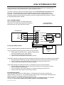
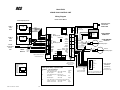
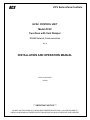
RCS
ZCV Series Zone Controls
HVAC CONTROL UNIT
Model ZCV2
Two Zone with Vent Damper
RS485 Network Communications
Rev K
INSTALLATION AND OPERATION MANUAL
DCN: 141-01064-06
1/01/09
*** IMPORTANT NOTICE ***
DO NOT USE THIS PRODUCT FOR BUILDING FREEZE PROTECTION! YOU ARE ADVISED TO
INSTALL A MECHANICAL FREEZE PROTECTION DEVICE ON YOUR SYSTEM FOR THIS PURPOSE.
OPERATION
The ZCV2 HVAC Zone Control Unit provides two independent heating and cooling zones when connected
to a single HVAC system. Each zone can be controlled by a “Wall Display Unit” or, if preferred, simply by
a wall mounted temperature sensor. Zonal temperature control is accomplished by controlling motorized
zone dampers to open or close the flow of conditioned air into each zone. The ZCV2 also has an RS485
communications port for connecting to control networks and controllers, such as the RCS CommStar
products.
The ZCV2 uses RCS Wall Display Units (WDU), which are similar looking to typical “thermostats”, but are
digital communicating multi-function user interfaces with graphical displays, user controls and a local
temperature sensor.
Please note that you cannot use standard thermostats with the ZCV2 HVAC Control Unit, only RCS
TS16 or TS40 Wall Display Units can be connected to it.
Installation of the ZCV2 control unit is easy. The control unit connects to the HVAC system’s thermostat
connections just like a traditional thermostat does. The Wall Display Units connect to the ZCV2 with a 4
wire cable. Each Zone damper is a two wire connection (or three wire for optional heavy duty dampers).
The ZCV2 will take care of providing the heating or cooling as needed to satisfy each zone’s
requirements.
Fully Independent Zone Control
Operation of the system is just like having two independent thermostats. Set each zone to the
heating/cooling mode desired and adjust the zone temperature as needed. The ZCV2 will automatically
delivery the heating/cooling needed to satisfy each zone’s requirement. Mixed modes are allowable
among the zones, that is, one zone may be set to heating while another may be set to cooling. The system
is fully automatic and has auto changeover capability. Heating calls are give priority over cooling calls.
The Zone Control Unit monitors the setpoint and modes of all zones and determines what heating calls will
be satisfied first and when all heating calls are satisfied, the system mode will switch to cooling to satisfy
all cooling calls as needed.
HVAC System Compatibility
Standard or Heat Pump HVAC System Types The ZCV2 can work with either standard Gas/Electric or
Heat Pump HVAC systems. System type is selectable on the control board.
For Standard HVAC systems, the ZVC2 can be set to work with either Gas heating or Electric heating.
For Heat Pump HVAC systems, the ZCV2 changeover valve operation can be set for either changeover
with cooling or changeover with heating.
Multi-Stage HVAC Compatibility
For Standard HVAC systems, the HVAC outputs support 2 stages of heating and 2 stages of cooling.
For Heat Pump HVAC systems, the HVAC outputs support 3 stages of heating (2 compressor/1 heatstrip)
and 2 stages of cooling.
Fresh Air Ventilation
The ZCV2 includes the “Smart Vent” feature which provides automatic fresh air ventilation. The Smart
Vent operation is controlled from the TS40 Wall Display Unit and provides several modes of manual,
timed and automation vent operation. A vent damper relay output is provided for control of a fresh air
intake damper.
DCN 141-01064 -06 1/02/09
2
Zone Damper Control
The ZCV2 features “Fail Safe” zone damper operation by using normally open dampers. In the event
that zonal control is lost, all dampers are open so that heating or cooling to all zones is possible until zone
control can be restored. During normal operation, when a zone calls for cooling, all other zones not
calling will be closed. At the end of the call, all dampers will return to open. This “all zones normally
open mode” also allows for system wide ventilation. Refer to the Damper section for specific damper
selection information.
Remote Communications
The ZCV2 control units have a RS485 serial communications port for network communications. Remote
systems can request zone data such as zone temperature, mode and/or operating status. They can also
set the operation of zones by sending new setpoints and heating/cooling modes. The communications
protocol (refer to RCS protocol document 150-00225) supports an extensive command set for a robust
control and monitor capability.
Up to 254 thermostat “zones” can be networked together in a HVAC control network using ZCV2’s along
with other RCS communicating thermostats. RCS Automation Control Units, such as the CommStar
Models CS30/308/48, can support up to 32 HVAC zones.
Outside Temperature Operation
The ZCV2 can use and display outside temperature information from a sensor attached to the ZCV2
control unit or from outside temperature data received from the network. In either case, the outside
temperature will be displayed on all zone WDU’s.
Outside Temp Sensor Attached to the ZCV2 When a outside temp sensor is attached to the ZCV2, it
is “enrolled” as an active sensor when the unit powers up and initializes. Changes in outside temperature
are sent to the wall display units for local display and also reported on the network.
Reporting Outside Temperature on the Network When an Outside Temp Sensor is attached to the
ZCV2 Outside Temp Sensor Input, the outside temperature will be reported on the network in response to
the Request Status message R=1. The outside temperature shows up as “OA=xx” in the status message
data string.
Displaying Network Outside Temp Data If a local outside temp sensor is not connected to the ZCV2,
outside temperature data can be received from the network and the ZCV2 will treat it just like a local
sensor is installed. If a local outside temp sensor has been installed on the ZCV2 it will inhibit
network outside temp data from being accepted. This is true even if a outside sensor was enrolled
and then disconnected but has not been un-enrolled by resetting the ZCV2.
Note that network provided outside temp data will NOT be reported in Request Status R=1 message
response (no “OA=” data will appear).
Wall Display Units
RCS Wall Display Units that are RCSLink2 products, such as Model TS16 and TS40 can be used with
ZCV2 controllers.
Note: At least one TS40 Wall Display Unit is required on the ZCV2 HVAC Zone Control Unit for
system configuration and access to the Installer Settings menus.
Reminder: You cannot use standard thermostats with the ZCV2 HVAC Zone Control Unit.
DCN 141-01064 -06 1/02/09
3
HVAC SYSTEM OPERATION AND SETUP
General Heating and Cooling Operation
In the HEATING mode, the heating system will be turned on at one degree below the setpoint and will turn
off at the setpoint. This turn on and turn off offset is referred to as the heating setpoint “delta T” and is
adjustable in the Installer Settings menu of the TS40 WDU. It is default set to the one degree operation.
In the COOLING mode, the cooling system will be turned on at one degree above the setpoint and will
turn off at the setpoint. Similarly, the cooling setpoint delta T is adjustable in the Installer Settings menu.
In the AUTO mode, the system will switch between heating and cooling as determined by the heating and
cooling setpoints and the current temperature. Once in a heating or cooling mode of operation, the
normal one degree setpoint control is maintained.
Setpoint Push Heating and cooling setpoints are forced to maintain a separation between them, with a
default setting of 4 degrees. If the heating or cooling setpoint is changed to be within the setpoint delta,
the system will automatically “push” the other setpoint to maintain the setpoint delta separation. The H/C
setpoint delta is also adjustable in the Installer Settings menu of the TS40 WDU.
Standard HVAC System Types
Gas or electric heating systems are considered “Standard” HVAC systems. These systems consist of an
indoor furnace/blower assembly and an outdoor AC condensing unit (for those systems with air
conditioning installed). These systems in general are referred to as central forced air HVAC systems.
You must configure the ZCV2 control unit for your HVAC system type for correct system operation.
Setup
Standard System Type Selection.
To set the Control Unit for standard Gas/Electric HVAC system operation, set the dipswitch DIPSW1 to
STD position (OFF). This is the default setting.
Fan Type Selection.
Gas systems do not require a fan output for heating operation. Set dipswitch DIPSW1-S2 to GAS (OFF)
system fan type operation.
Electric (and hydronic) heating systems do require a fan output with the call for heating. Set dipswitch
DIPSW1-S2 to ELECT (ON) for ELECTRIC system fan type operation.
Be sure to check your HVAC system’s requirements!
Heat Pump HVAC System Types
Heat Pump HVAC systems are combined heating and cooling systems. The system consists of an indoor
“air handler” (a blower fan and coil assembly) and an outdoor unit. Heat pumps change from heating
mode to cooling mode by switching the refrigerant flow using a “changeover” or “reversing valve”. In both
heating and cooling operation the compressor and fan outputs are on and the state of the changeover
output determines if heating or cooling is being provided. Heat pumps can have one or two stages of
compressor operation plus an optional third stage of electric heat strips.
The third stage of heating will be turned on when the current temperature falls 5 deg below the current
setpoint and will turn off at 3 degrees below the setpoint.
DCN 141-01064 -06 1/02/09
4
Setup
Heat Pump System Type Selection
To set the Control Unit for Heat Pump HVAC operation, set the dipswitch DIPSW1-S1 to HP (ON).
Changeover Type Selection
Most heat pump systems are designed to work normally in the heating mode and require a change over
output for cooling output. Set the System configuration dipswitch DIPSW1 as follows for your system
type.
Changeover with Cooling: Set DIPSW1-S2 to CO-C (OFF) This is the default setting.
Changeover with Heating: Set DIPSW1-S2 to CO-H (ON) position.
Note: during Heat Pump operation the changeover relay, once engaged, will stay on until the
Minimum Off Time (MOT) delay expires before dropping out. If another call commences before the
MOT timeout, it will avoid unnecessary cycling of the changeover valve.
Check your HVAC system requirements for correct settings.
Minimum Run Time (MRT)
The ZCV2 control unit has a Minimum Run Time after the start of any heat or cool call. This 6 minute
minimum run time assures even heating and cooling cycles. Minimum Run Time will keep the system on
even if you change the setpoint to a temperature that would satisfy the call, until it expires. Changing the
Mode to OFF will cancel the MRT and the system will turn off immediately. MRT can be adjusted in the
Installer Settings Menu of the TS40 WDU.
Note: MRT status is shown in the TS40 WDU system status indicator.
Minimum Off Time (MOT)
The ZCV2 control unit has a Minimum Off Time after any heat or cool call. This 6 minutes delay prevents
rapid heating/cooling cycles and also provides “short cycle protection” for compressor calls. This delay
may be noticeable when you change a zone setpoint and it does not respond immediately due to another
call have been recently completed and the MOT delay timer is preventing the restart of the system. The
MOT delay time can be adjusted in the Installer Settings Menu of the TS40 WDU. There is a minimum of
5 minutes delay to assure compressor protection.
Note: MOT status is shown in the TS40 WDU system status indicator.
DCN 141-01064 -06 1/02/09
5
NETWORK OPERATION
The ZCV2 controllers have RS-485 serial communications that allows remote commands generated by
other systems to be received by the ZCV2. These remote commands can change the individual zone
setpoint, temperature and modes or may request current status of a zone temperature, setpoint and
mode. Whenever new commands are received, the WDU will switch its display to show the updated
information for three seconds and then return to the current temp display.
RS-485 connections are a twisted pair multi-drop network that can have up to 255 devices connected to
one pair of wires. With use of a RCS Star Wiring Hub, wiring can also be “star” or “homerun” from each
connected device to the host system, such as RCS CommStar network control units.
Network Addressing
The RS485 address is set from a TS40 Wall Display Unit Installer Settings Menu or from a TS16 WDU
setup menu. Refer to each devices manual for specific network address setting instructions. Network
address 0 is reserved for the Host control unit and address 255 is reserved for global commands.
Each zone in the ZCV2 control unit is treated like a separate thermostat and has its own RS485 address.
When you set the address for the control unit, you are setting the base address for Zone 1. Each zone is
sequentially addressed from this number. Note that zone addresses are assigned to all zones on the zone
controller, even if they are not used.
For example: if the zone control unit is set to address 1, each zone address is as follows:
Zone 1 = network address 1
Zone 2 = network address 2
If the next device in the network is a ZCV2, it would need an address of 3 and the zones would be
addressed as follows:
Zone 1 = network address 3
Zone 2= network address 4
Communications Parameters
The ZCV2 communications uses half-duplex RS485, 9600 baud, 8 data bits, no parity, 1 stop bit and no
flow control.
The RS485 network connects to the screw terminal connector. The D+ and D- and GND connections are
required.
Communications Protocol
The ZCV2 Zone Controllers uses the RCS serial communications protocol for HVAC control devices. This
is an ASCII-based message protocol. Refer to the RCS RS-232/485 communications protocol document,
PN: 150-00225, for detailed information on serial commands to communicate with the ZCV2 HVAC control
units.
Note that not all commands in the protocol document are applicable to or supported by the ZCV2. The
protocol document has an appendix that identifies specific ZCV2 commands.
DCN 141-01064 -06 1/02/09
6
INSTALLATION
LOCATION AND MOUNTING
Install the Control Unit in a protected, convenient, INDOOR location near the HVAC system or in a service
accessible area such as an equipment closet or garage.
Mount the Control Unit in a vertical position on a wall or sturdy structural member. The unit may be
mounted on the HVAC system but care should be taken to avoid the hot burner section or high vibration
areas.
Wall Display Units
Wire specification: 4 conductor, 18Ga thermostat wire, 22Ga twisted pair or Cat 3/5 wire (preferred)
The Control Unit connects to each zone’s Wall Display Unit or Sensor by four wires. In retrofit
applications, the existing thermostat wiring may be used, however, for best results and in new
construction, a Category 5 twisted pair cable is recommended.
ZCV2 CONTROL UNIT
WALL DISPLAY UNIT
ZONE 1 WDU
GND
GND
G
+12V
+12VDC +V
CLOCK
C
DATA
D
CLK
DATA
Standard Thermostat Wire or Cat 5 cable
can be used.
Standard thermostat Wire color code
Ground: Green
12VDC: Red
Clock: Yellow
Data:
White
Cat 5 Wire color code
Ground: Brown pair (twisted together)
12VDC: Blue Pair
Clock: Orange Pair
Data: Green Pair
CAUTION! Do not mis-wire the Wall Display Units – damage may result. Check the wiring before
applying power to the Control Unit.
Wiring To The Outside Temp Sensor (if installed)
Wire specification: 2 conductor, 22Ga twisted pair or Cat 3/5 wire (preferred)
Black
Model OS5
Outside Temp Sensor
Red
Sensor wiring is not polarized.
DCN 141-01064 -06 1/02/09
7
S1
S2
OS Sensor
Damper Wiring
Wire specification:
RD Series dampers:
requires 2 conductor cable
RDM Series dampers: requires 3 conductor cable
Recommended wire:
18/20GA thermostat wire
The ZCV2 HVAC Control Unit has two zone damper output relays plus a fresh air vent damper output.
These SPDT relays are rated at 1 Amp, 24VAC. Zone outputs support either two wire (normally open,
power close/spring return) or three wire dampers (power open, power close).
NOTE! ZCV2 Zone Controllers Require Normally Open Dampers
Without any heating or cooling calls, all zone dampers are open. When a zone calls for heat/cooling, all
other zones that are not calling will have their dampers powered to the closed position.
This provides two important functions. First, if there is a zone output failure, the zone is still capable of
getting heating or cooling. Second, it allows for ALL zone ventilation during periods of no heating or
cooling (continuous fan mode).
RCS Round Motorized Dampers
RD Series round motorized dampers Standard dampers feature an extra rigid barrel with a self sealing
blade that provides a 99% seal. Sizes 6 to 14 inches. They are 24VAC, 2 wire, 2 position, power
close/spring return, normally open dampers. Current draw is 0.5 amps each. Rated for continuous power
in the closed position. Part number: xxRDNO, where xx is damper diameter.
RDM Series round motorized dampers Heavy duty dampers have the same extra ridge barrels of the
RD series, coupled with a commercial heavy duty 3 wire damper motor. Sizes 6 to 20 inches. They are
powered open and powered close. Current draw is 0.1 amps max each. Rated for continuous power in
the open and closed positions. Part number: xxRDMNO-FP
The xxRDMNO-FP dampers are the preferred damper for use with the ZCV2 control units.
Zone Damper Wiring
RD Series 2 wire Dampers
24VAC Common
Relay Normally Open
24C
Zone 1
NO
Yellow
Normally Open Damper
Power Close
Spring Open
Yellow
RDM Series 3 wire Dampers
24VAC Common
24VAC Return
24C
PWR
24R
Controller 24VAC Power Transformer
24C
Vent
NC
Damper
NO
24V R
24C
Zone 1
NO
Normally Open Damper
Power Close (override to close)
Power Open (continuous power)
1 Com
2 Open
3 Close
24VAC Common
DCN 141-01064 -06 1/02/09
8
Vent Damper Wiring
RD Series 2 Wire Dampers
24C
PWR
24R
24V R
24C
Vent
NC
Damper
NO
Yellow
Normally Open Damper
Power Close
Spring Open
Yellow
24C
Zone 1
NO
RDM Series 3 Wire Dampers
24C
PWR
24R
24V R
24C
Vent
NC
Damper
NO
Normally Open Damper
Power Close (1-3)
Power Open (1-2)
1 Com
2 Open
3 Close
24C
Zone 1
NO
POWER
The ZCV2 HVAC Control Unit requires 24VAC power. Power is provided by an external transformer (not
supplied). This transformer must be rated for the max damper load. Calculate the transformer VA rating
required by adding up the current draw for the number of dampers attached for the worst case load when
only one zone calls and all others close.
(Total dampers -1) x (amp draw for each damper) x 24 = transformer VA rating.
Ex: ZCV2 2 zone controller: (2-1) x (.5A) x 24 = 12VA, so use a 20VA transformer.
DCN 141-01064 -06 1/02/09
9
NETWORK WIRING
Network Wiring
Connecting to RS485 Communications Ports
The RS485 communications port is a 2 wire (D+ and D –) plus ground, half-duplex network connection.
Wiring options are direct to the com port, daisy chained to other thermostats, or wired to a RCS RS485
hub to allow star or homerun wiring.
Host System
RS485 port
ZCV2 Control Unit
RS485
Up to 4000 ft
12V
Gnd
D+
D-
Gnd
D+
DRS485 Wiring Note
Always wire + to + and – to –, regardless of the D+/ D- or A/B or TX/RX labels.
RS485 Wiring Methods
The ZCV2 control unit can be wired by three methods:
1. Direct connection to RS485 com ports (as above)
2. Multi-drop (daisy chained) to other thermostats/devices
3. Homerun wired to a Star Hub.
Multi-drop Wiring
Host System
RS485 port
12V
Gnd
D+
DRS485
RS485
Gnd
D+
D-
RS485
Gnd
D+
D-
Gnd
D+
D-
Star Hub Wiring
CommStar Model CS308 or 8AH485
8 channel Star RS485 Hub
100 ohm line
termination resistor
recommended on
last device
ZCV2
Control Unit
RS485 Port
RS485 Port
RS485 Port
RS485 Port
RS485 Port
RS485 Port
RS485 Port
RS485 Port
RS485 Port
ZCV2
Control Unit
RS485 Port
ZCV2
Control Unit
RS485 Port
ZCV2
Control Unit
RS485 Port
DCN 141-01064 -06 1/02/09
10
Connecting to RS232 Communications Ports
Using Model 485DB9TB RS232 to RS485 Converter
PC or
Control System
DB9 Serial
Com Port
Model 485DB9TB
ZCV2 Control Unit
RS485
+12 G G TD(B) TD(A)
Gnd
D+
D-
Using Model 485PB RS232 to RS485 Converter
ZCV2 Control Unit
RS485
5 Port
RS485
Hub
PC or
Control System
V
G
B+
A-
Gnd
D+
D-
DB9 Serial
Com Port
Standard PC serial cable
(DB9 to DB9)
DCN 141-01064 -06 1/02/09
Power
Transformer
11
HVAC SYSTEM CONNECTION
Electrically, the ZCV2 Control Unit looks like a standard thermostat to your HVAC system. All connections
to the HVAC systems are made at the normal thermostat connection on the HVAC unit.
Refer to the following HVAC wiring information for the type of HVAC system the ZCV2 control unit is being
connected to, Standard or Heat Pump. Refer to your HVAC system’s documentation for specific
information on its thermostat connections.
Standard Gas/Electric HVAC System Wiring
See ZCV2 power options
24C
PWR
24R
ZCV2 Control Unit
Standard HVAC System
HVAC SYSTEM
THERMOSTAT CONNECTION
RC 24VAC
Optional
separate RC
RH 24VAC
RED
W1 HEAT
WHITE
W2/CO
ORANGE
G FAN
GREEN
Y1 COMP
YELLOW
Y2 COMP
BROWN
C 24VAC COMMON
R 24VAC RETURN
W 1 Heat Stage 1
W2 Heat Stage 2
G Fan
Y1 Compressor Stage 1
Y2 Compressor Stage 2
JP1: RH and RC Jumper
This commons both RH and RC for normal single transformer HVAC systems.
Cut JP1 jumper for separate RH and RC transformer systems.
NOTE: When jumper JP1 is cut, W1 and W2 are switched to RH. G, Y1
and Y2 are switched to RC.
JP1
Heat Pump HVAC System Wiring
See ZCV2 power options
ZCV2 Control Unit
24C
PWR
24R
Heat Pump HVAC System
HVAC SYSTEM
RC 24VAC
RH 24VAC
THERMOSTAT CONNECTION
Optional
separate RC
RED
W1 Heat
WHITE
W2/CO
ORANGE
G Fan
GREEN
Y1 Comp
YELLOW
Y2 Comp
BROWN
C 24VAC COMMON
R 24VAC RETURN
W1 Aux Heat Stage 1
O/B Changeover (CO) Valve
JP1
DCN 141-01064 -06 1/02/09
G Fan
Y1 Compressor Stage 1
Y2 Compressor Stage 2
JP1: RH and RC Jumper . Do not cut.
Leave RH and RC connected for Heat Pump Systems
12
NOTE: Set correct Changeover
value operation for O (CO w/Cool)
or B (CO w/Heat) mode on
DIPSW1 on the control board.
SYSTEM CHECKOUT
It is strongly recommended that you hook-up and run a simple bench test before installing this controller.
Not only will this save you time in system checkout but will also familiarize you with the ZCV2 operation.
Quick Test
NOTE: Before power up, set the dipswitch, DIPSW1, to ALL OFF.
1. Connect a Wall Display Unit to ZONE 1 input on the Control Unit with a 3 foot 4 wire cable.
2. Connect the 24VAC transformer to the Control Unit.
3. Plug the transformer into a 110v outlet and apply power to the Control Unit.
4. Verify Power Status LED is flashing.
5. Verify the WDU display comes on and shows the current temperature.
a. If no display or a “CF” display is shown on the WDU, double check your wiring.
b. Do not proceed until the current temperature is displayed on the WDU and communications
between it and the Control Unit is OK. Any problems will result in a “CF” (Communications Failure) display
on the WDU.
6. Press the Fan button on the WDU. The Control Unit Fan LED and relay should turn on. Also all
damper LED’s should turn on except Zone 1.
7. Press the Fan button again. The Fan LED and all relays should turn off.
8. Press the Mode button until the WDU is showing “H” for Heat Mode.
9. Press the Setpoint Up button until the setpoint is above the current temperature. The Heat LED and
relay should come on.
10. Press the Mode button until the WDU is showing “O” for OFF. The Heat LED and relay will turn OFF.
11. Press the Mode button until the WDU is showing “C” for Cool Mode.
12. Press the Setpoint Down button until the setpoint is below the current temperature. The Cool and Fan
LEDs and relays should turn on.
13. Press the mode button until the WDU is showing “O” for OFF Mode.
14. All LEDs and relays should turn off.
15. When you have successfully completed all these tests, you have verified that the Control Unit and the
WDU are working and communicating correctly.
Communications Test with a PC
1. With the Control Unit and WDU connected as above, proceed with connecting the ZCV2’s RS485
connection to a PC serial port (COM1) using a RS232 to RS485 converter (Model 485DBTB or eqv).
Note: If not using a RCS RS485 Converter, be sure the converter supports Send Data Control.
2. Set ZCV2 base address to 1
3. Start the Hyperterm terminal emulator program in Windows/Accessories/Communications/Hyper
Terminal.
4. Set Hyperterm communications parameters for COM1 to 9600 baud, no parity, 8 data bits, 1 stop bit
and NO flow control.
5. Set CAPS lock on (Commands are case sensitive).
6. Send the Request for Status command R=1. Type “A=1 R=1” followed by the carriage return (cr).
7. ZCV2 should respond with the R=1 status response showing temp, setpoint, mode and fan for zone 1
(A=00 O=1 Z=1 T=(current temp) SP=70 M=0 F=0)
8. Set zone 1 Mode to Heat. Type “A=1 M=H (or 1) cr”.
9. Zone 1 WDU should change to show the new mode is “H”.
10. Set zone 1 setpoint to 78 degrees. Type “A=1 SP=78 cr”
11. Zone 1 WDU should change to show a setpoint update of “78”.
12. If the WDU responds properly to these commands, proceed with installation.
It is recommended that you install the ZCV2 and then rerun these quick tests BEFORE you connect the
Control Unit to the HVAC system. You will be confident that the ZCV2 is working correctly before you
attempt to interface the HVAC system.
DCN 141-01064 -06 1/02/09
13
HVAC SYSTEM QUICK TEST
In the event that you have difficulty with the ZCV2 controlling the HVAC system, you can perform the
following quick test to confirm that the HVAC system is working correctly.
The ZCV2 Control Unit connects to the HVAC system at the normal thermostat connections on the
HVAC unit. Standard thermostat control of the HVAC systems consist of contact closures in the
thermostat. You can verify that your HVAC system is working correctly by duplicating these contact
closures by shorting across the proper terminals on the HVAC systems thermostat connection. Refer to
the following HVAC system example.
HVAC SYSTEM EXAMPLE
This is a simplified diagram of an HVAC System and
Thermostat. The Thermostat operates like switches to
control the HVAC Fan, Heat, and Cool functions.
HVAC SYSTEM
STANDARD GAS/AC
FURNACE AND BLOWER UNIT
Thermostat
THERMOSTAT
R 24VAC HOT
FAN
G FAN
HEAT
W HEAT
COMP
Y COMP
FAN
RELAY
24VAC
GAS
VALVE
C 24VAC COMMON
For Standard HVAC systems:
COMP
RELAY
Go to the HVAC system’s thermostat connection terminals
Verify FAN operation by shorting across the R to G (Fan) terminals
• HVAC system fan should come on. (Caution: Delays may be
part of normal start up cycle, check manual)
• If not check HVAC system power and fuses.
• If power is OK, HVAC system is NOT working correctly.
Outdoor
Condensing
Unit
Verify HEAT operation by shorting across R to W (Heat) terminals (A Fan call is not necessary for gas furnaces)
• Heating operation should start. (Caution: Delays may be part of normal start up cycle, check manual)
• If not, check wiring, check 24VAC power is on R terminal. (measured across R to C).
• If power is OK, HVAC system is NOT working correctly.
Verify COOL operation by shorting across R to Y (Compressor) and R to G (Fan) terminals
• Cooling operation should start. (Caution: Short Cycle Protection 5 minute delays are normal
between calls and may delay start)
• If not, check wiring, check 24VAC power is on R terminal (measured across R to C)
• If power is OK, HVAC system is NOT working correctly.
For Heat Pump systems:
Follow the above test to check the FAN operation. If FAN works OK, then power is verified also.
Short across R to Y and R to G. You should get either Heat (normal) or Cool operation depending on the
whether your system is changeover with cool (normal) or heat.
Short across R to Y, R to G and R to O/B(Changeover terminal) to get opposite heat or cool operation
from step 2. If any of these checks fail, the HVAC system is not working correctly.
DCN 141-01064 -06 1/02/09
14
RCS
Model ZCV2
2 ZONE HVAC CONTROL UNIT
Wiring Diagram
Rev K Control Board
Wall Display Units
75
ZONE 1
TS40
WDU
75
ZONE 2
TS40
WDU
Outside
Temperature
Sensor
OS5
Alternate Power
Transformer
24VAC 40VA
G
R
Y
W
G
R
Y
W
Red
Black
RS485
Network
Green
Red
Yellow
White
180-01006-11 ZCV2 REV K
2A
G
R
Y
W
Green
Red
Yellow
White
G G
R 12
Y C
W D
Red
White
S1
S2
Ground
Data +
Data -
GND
D+
D-
Optional RS485 Connector
8 Wire Modular Jack
RJ45
JACK
GND
12V Zone 2
CLK Wall Display Unit
DATA
DIPSW1
STD
S2
HP
S1
S2 OFF
STD GAS
HP
CO/C
24C B
24R R
Vent
Damper
24C R
NC G
NO W
Zone 1
Damper
24C R
NO W
Zone 2
Damper
24C R
NO W
Red
White
HVAC 24VC
System 24VH
Heat 1
*Heat 2
Fan
Comp1
Comp2
S2 ON
ELECT
CO/H
RC
RH
W1
W2/O
G
Y1
Y2
DIPSWITCH
HVAC SYSTEM SETUP
S1
Sets HVAC System Type
STD - Standard System Set S1 OFF (default)
HP - HP System
Set S1 ON
S2
15
VENT DAMPER
RDM Series
24VAC
If S1= Standard System – Sets Fan Type
Gas System
Set S2 OFF (default)
Electric System
Set S2 ON
ZONE DAMPERS
RD Series
Zone 1
Normally Open
Yel
Yel
24VAC
Yel
Yel
Zone 2
Normally Open
24VAC
Thermostat Connection
HVAC System Setup – Dipswitch SW1
S2
1 24V Com
2 Open
3 Close
Red
White
Outside
Sensor
RS485
Com
Port
24VAC
Power
RC/RH Jumper JP1
Cut for separate
Heating and Cooling
Transformers
Optional RS485 RJ45
Connector Pinout
1 Data+
2 Data 12345678
3 NC
4 NC
5 NC
6 NC
7 NC
Front View
8 GND
DCN 141-01064 -06 1/02/09
G
12
C
D
GND Zone 1
12V Wall Display Unit
CLK
DATA
Status LED
Fuse F1
Mini ATO type
Position
Left
Right
Left
Right
If S1 = HP System – Sets Changeover (CO) Valve Type
O Mode: CO with Cool
Set S2 OFF (default)
Left
B Mode: CO with Heat
Set S2 ON
Right
Blue
Red
White
Orange
Green
Yellow
Brown
Typical Thermostat
Wiring Color Codes
C
R
W
W2
G
Y1
Y2
24V Com
24V
Heat 1
Heat 2/CO*
Fan
Comp1
Comp2
HVAC System
Standard or
Heat Pump
Set DIPSW1 to
Correct System Type
*Note: W2 = O (Changeover) when
Heat Pump System Type Selected