1
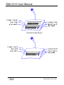
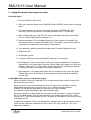
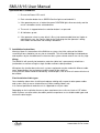
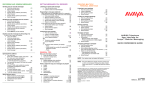
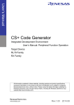
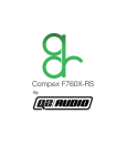
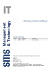
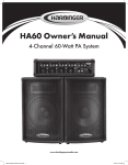
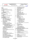
* +
-----
!" #$% & '' ( $) ))
!" #$ % & '' ( , )
+
+ .
+
+ /
Serial Microphone Unit (SMU)
8 & 16 Button Versions
User Manual V2
SMU 8/16 User Manual
1. Revision History
Version
A
B
1.0
1.01
1.02
2
Modifications
Original issue. File renamed from dmic-006.doc
Wiring diagram changed to show new type factory fitted cable
PSF10/2
Add BGM selection mode to Appendix 3
Re-Formatted Version
New section ‘Safety Considerations’ replaces Appendix 3
Appendix 1 split to a separate document.
Add to spec. freq.resp and s/n ratio
Add SMU16 and drawings
Date
15/4/99
20/5/99
6/7/99
23/7/99
6/10/00
CN3311
18/01/02
10/3/04
© Copyright Audix Systems. 2005
DISCLAIMER
This manual contains information that is correct to the best of Audix Systems knowledge. It is intended to be a guide and
should be used as such. It should not be considered as a sole source of technical instruction, replacing good technical
judgement, since all possible situations cannot be anticipated. If there are any doubts as to exact installation,
configuration and/or use, call Audix Systems at
+44 (0)1799 540888
ACKNOWLEDGEMENTS
All trademarks are recognised
page 2 of 14
21004 SMU8 and 16 V2.doc
SMU 8/16 User Manual
2. Table of contents
1.
2.
3.
4.
5.
Revision History............................................................................................................2
Table of contents ..........................................................................................................3
Product Description ......................................................................................................4
SMU8 Specifications.....................................................................................................5
Paging Microphone Operating instructions ...................................................................7
Used with Alpha ...............................................................................................................7
Using SMU8 with a Vector or V32 based system.............................................................7
Using SMU8 to make programme changes to a Vector system. ......................................8
6. Background Music Controller (BGM) ............................................................................8
Operation Music broadcast...........................................................................................9
7. Installation instructions .................................................................................................9
Wiring. ..............................................................................................................................9
Fixed Installation Cable types. .........................................................................................9
8. Setting Up...................................................................................................................10
Connector pin-outs and Jumper settings........................................................................11
9. Safety Considerations.................................................................................................14
10.
Glossary of terms ....................................................................................................14
page 3 of 14
21004 SMU8 and 16 V2.doc
SMU 8/16 User Manual
3. Product Description
The SMU8/16 is desk mounted microphone console for primarily designed for use with Audix
Systems Public Address and Voice Alarm controllers.
The unit features eight ore sixteen “selection” buttons which are typically used to select zones
or groups of zones ready for spoken announcement.
A ninth (17th) button is the press-to-talk key, which used by the operator to make a call. A
“speak-now” indicator is associated with this button.
Led indicators provide comprehensive status display.
Red LED’s showing when zones are busy, green LED’s show when calls are successful.
Customers button designations can be added on smart printed labels behind a glass window
above the selection buttons.
The unit features a good quality dynamic microphone and a low noise pre-amp with balanced
input.
Maximum intelligibility is maintained with a combination of digitally controlled pre-amp gain, and
dynamic gain adjustment (compressor-limiter) in the digital domain.
An optional LED indicator shows that when the user is talking at or above the limiter threshold.
A digitally synthesized 20kHz monitor tone for the Audix Systems FMS is injected directly at the
microphone head, with innovative circuitry able to detect open or short circuit failure of the
microphone.
The microphone console features a choice of 2 or 3 built in pre announcement chime signals.
There is independent adjustment for the chime volume.
Audix Systems may offer a service to customise an SMU8/16 with high quality digitally
recorded pre-announcement tones to customer requirements.
Some features of the SMU816 may not be supported by the PA control equipment that the
SMU8/16 is used with.
Due to continued development, Audix Systems reserves the right to change any of the
operational features of the SMU8/16 described in this document.
page 4 of 14
21004 SMU8 and 16 V2.doc
SMU 8/16 User Manual
4. SMU8 Specifications.
Power supply voltage range
Supply current (max. inrush)
Supply current (typical)
Audio output nominal
Audio output max.
Output impedance
Load impedance
Distortion T.H.D.
Signal to Noise ratio
Peak overload indicator threshold
Audio sampling rate
a-d and d-a resolution
Pre-announcement chimes 1,2,3, total duration
Data link
Baud rate
Frequency Response (Mic head)
Microphone gain trim range
Microphone gain reduction in idle (survey) state
20 – 35V d.c..
500mA
110mA @ 24V
0dBu
+10dBu
< 50 ohms
> 600ohms
< 0.05%
55dB
0dB or >2dB limiter gain reduction
48kHz
16 bits
5 seconds
RS485 half duplex
9600
150Hz-7kHz (+3dB)
20dB
-22.5dB
Surveillance tone adjustment range
Surveillance tone adjustment resolution
Surveillance tone stability
-20dBu – -50dBu
3dB
o
100ppm/ C
Operating temperature range
Max Humidity
EMC operating environment
(As defined by EN50081-1, EN50082-1)
Manufactured to Safety Standard
0 – 40 C
85% non-condensing
Domestic, Commercial,
Light Industrial.
EN60065:1998
o
The unit is connected to the PA system via a three or four pair cable.
Pair 1: The unit is powered from a nominal 24V D.C. supply.
Pair 2: Data COMM’s is by a RS485 half duplex link running at 9600 baud.
Pair 3: Audio output from the unit is at balanced line level audio 0dBu nominal.
Pair 4: (Optional) for driving 2 auxiliary indicator LED’s.
Each pair should be individually screened, with a common overall screen connected to
earth.
page 5 of 14
21004 SMU8 and 16 V2.doc
SMU 8/16 User Manual
Zone Selection Microphones
page 6 of 14
21004 SMU8 and 16 V2.doc
SMU 8/16 User Manual
5. Paging Microphone Operating instructions
Used with Alpha
1. Ensure the Power LEDs are lit
2. Each zone selection button has a Red BUSY and a GREEN Confirm light associated
with it.
3. If the operator presses a zone select button the green CONFIRM light shine
constantly (NOTE that the zone is not connected until the PTT is pressed).
4. When the operator press their PTT the zone is connected, the green confirm light
stays lit and the Speak (Green) indicator is lit.
5. Make the broadcast. The microphone panel has a pre-amplifier co-located in the
room which utilises a compressor/limitter cicruit. This boosts a quiet voice and limits
a loud voice to enable consistent loudness of broadcasts
6. If the operators speaks too loudly the red triangle “Overload” indicator flashes
7. Release the PTT.
8. All indicators go out.
9. If a zone is BUSY the corresponding RED indicator is lit constantly.
10.If the operator selects a zone which is Busy (not recommended) due to a higher or
equal priority user accessing the zone the Confirm light initially comes on continually.
However, when the PTT is pressed the Confirm light flashes indicating the operator
is being over-ridden and therefore not making a broadcast.
11.If the operator is of a higher priority than the user already on the system the green
Confirm light comes on constantly and a broadcast can be made (over-riding the
current user).
Using SMU8 with a Vector or V32 based system.
When the SMU8 is idle it will show red LED’s on each button where a zone or zones that
the button may call is busy.
When you wish to make an announcement, the first step is press the buttons that are
labelled with the zone names you wish to call, this is called selecting the zones.
A green LED will light by each button to show that it has been selected.
Any selection may be cancelled by pressing the button again.
When the selection has been made the next action by the announcer is to press and hold
the PTT or speak button. Until this point announcer has had no effect on the PA system.
Once the PTT is pressed the pattern of LED’s changes to show green for the zones that are
reached by the call.
A rapidly flashing green LED by the speak button, indicates that the pre-announce chime is
active and the announcer should wait until this green LED stays solidly on. This is the
Speak-now indication.
page 7 of 14
21004 SMU8 and 16 V2.doc
SMU 8/16 User Manual
Whilst holding the PTT button, the announcer should then talk steadily and clearly into the
microphone with their mouth about 10 to 20 cm. from the microphone head.
The call ends when the announcer releases the PTT button, thereby turning off the
microphone, indicated by the Green LED’s turning off.
The SMU8 reverts to showing red LED’s for busy states of all the zones programmed on its
buttons.
Note that when a selection is started only the busy LED’s on the selected zones are shown.
This feature, called “selections-busy ” makes it easier for a caller see when his call zones
become free.
Using SMU8 to make programme changes to a Vector system.
The SMU8 must be switched to PMCV compatible mode to achieve this.
Remember to switch back to the normal SMU8 mode after programming is completed.
6. Background Music Controller (BGM)
The panel is available as an 8/16 button background music controller. The unit is supplied
without a microphone in both desk top and rack mounted formats. The units can be used
for routing music sources to specified zones.
Rack Mount
page 8 of 14
21004 SMU8 and 16 V2.doc
SMU 8/16 User Manual
Operation Music broadcast
1. Ensure the Power LEDs are lit
2. Each selection button has a GREEN Confirm light associated with it.
3. If the operator presses a button the green CONFIRM light shine constantly and the
music is broadcast to the selected zones
4. The music is stopped when the selection button is re-pressed.
5. All indicators go out.
6. If the operator selects a zone which is Busy (not recommended) due to a higher or
equal priority user, the Confirm light flashes indicating that the operator is being
over-ridden and therefore not making a broadcast.
7. Installation instructions
Warning: Upon first connection of the SMU8 to a system, the initial setting of the 20kHz
surveillance tone should be set very low or turned off. This will avoid damage to loudspeakers
and amplifiers by the inaudible tone in the event that system volume controls are set very high.
Wiring.
The SMU8/16 will normally be located on a desk or table, but is permanently wired into a
junction box or wall box using the single flexible multicore cable provided.
Wiring from the junction box to the main systems equipment may be made with different cable
types, depending on the environment and the length of the cable run.
In any case the cable should be individually screened pairs, with an over-all screen which must
be earthed.
Fixed Installation Cable types.
Care should be taken when installing microphone cabling with respect to other power cables
and systems likely to cause interference e.g. Mains cabling, Motors etc.
In its normal operational mode the unit is supported on a 3 pair cable.
Depending on the installation there may be a requirement to use fire resistant or LSF cables.
Audix Systems can offer advice, based on previous experience as to suitable cable types and
maximum cable lengths.
page 9 of 14
21004 SMU8 and 16 V2.doc
SMU 8/16 User Manual
8. Setting Up.
There are a number of pre-set controls that must be set during system commissioning.
The location of these controls is shown in the figure below.
Use the channel gain control on the PA system to adjust the volume of the microphone. Do not
adjust the “mic pre-set gain control” which has been factory set to match the characteristics of
the microphone, and will not normally be adjusted on site.
The “mode control” will normally be set for SMU Basic Mode (E), unless the unit is being used
to program a Vector (F).
See the table in section ‘Connector pin-outs and Jumper settings’ for other modes.
The “chime switch” will be set to select the required chime. It is also used to adjust the chime
volume after the mic volume has set on the PA system. To turn the chime off completely select
Position 0 on this switch.
page 10 of 14
21004 SMU8 and 16 V2.doc
SMU 8/16 User Manual
Connector pin-outs and Jumper settings
Main system connection: 10W Terminal Block. PL1
Pin
Signal name
Signal description
1
0V
Power supply return and ground connection.
2
+24V
+24V nom. (20 to 35V) d.c. power supply input.
3
OP+
Audio signal +ve
4
OPAudio signal –ve
5
LD1
Active low to light Auxiliary green LED
6
CEN
Active low to enable chime in PMCV compatible mode
7
LD2
Active low to light Auxiliary yellow LED
8
D+
RS485 data +ve
9
DRS485 data –ve
10
0V.
Screen connection for data pair.
Jumper links on the D780 PCB.
The following jumpers are used to set the card up for different applications, the table below shows
how they will normally be set at the factory for the SMU8.
J6
(Fit 2-3) Selects the Serial output to the LED’s on the PCB or to the
expansion connector PL2
J7
(Fit 1-2) Selects the serial input from the switches on the PCB or from the
expansion connector PL2
J2
Do not fit. Used for Flash boot ROM option.
J3
Do not fit. Used for Flash boot ROM option.
J4
Fit. Card uses boot EPROM 27C040.
J5
Fit (1-2). Card uses boot EPROM 27C040.
J1
Do not fit. Used as reset on factory test.
page 11 of 14
21004 SMU8 and 16 V2.doc
SMU 8/16 User Manual
Preset controls.
Figure shows the pre-set controls which are accessible behind a metallic label below the
front edge of the front panel.
These controls will be set up during installation using the above information.
They should not be adjusted with out an understanding of the effects on the Public Address
or Voice Alarm system. Setting not listed in the table may cause the SMU8 to function
unpredictably.
Mode Switch settings
D
E
F
BGM selector mode
SMU8 basic mode
PMCV compatible mode for Vector Programming.
From V1.02
All versions
From V1.01
Chime Switch settings
0
4
5
6
7
8
9
A
B
C
D
E
F
Disable chime
Chime 1 Volume min.
Chime 1, louder.
Chime 1, louder still.
Chime 1 Volume max.
Chime 2 Volume min.
Chime 2, louder.
Chime 2, louder still.
Chime 2 Volume max.
Chime 3 Volume min.
Chime 3, louder.
Chime 3, louder still.
Chime 3 Volume max.
20kHz Switch settings
0
1
x
F
No surveillance
20kHz minimum output level.
Increasing by 3dB steps
20kHz maximum output level
page 12 of 14
21004 SMU8 and 16 V2.doc
SMU 8/16 User Manual
Wiring diagrams:
Wiring of factory fitted cable.
Note that three-pair cable may be used for systems where no auxiliary LED indicators are
required. (A chime-enable wire is not normally required.)
The supplied cable is 2 metres long, which may be extended using cable of a similar type.
Wiring of cable used on PMCV8 & 16 (Vector microphones) and early SMU models.
page 13 of 14
21004 SMU8 and 16 V2.doc
SMU 8/16 User Manual
9. Safety Considerations.
Review the following safety precautions to avoid injury and prevent damage to the product. The
product should only be used as specified.
The SMU8 should be operated from a suitable DC supply of nominally 24V. Use only the
correct power source, which must contain current overload protection to protect the wiring
between the system and the SMU8.
Do not disconnect the cable from the product whilst the Voice Alarm system is powered.
Do not operate in wet or damp conditions or expose to dripping or splashing.
Do not operate in an Explosive Atmosphere
This product may be incorporated into a Monitored Voice Alarm system. If so, to tamper with
any of the setting of the SMU8 unit may cause a Fault Condition warning on the Voice Alarm
control unit. In these circumstances the restoration of normal operation of the system may not
be possible without access to the Main Voice Alarm Equipment by qualified personnel.
10. Glossary of terms
FMS
Fault Monitoring System: Audix Systems BS5839 compliant monitoring system,
integrated into all Audix Systems Voice alarm components.
SMU
Serial-link Microphone Unit. Audix Systems microphone console with a serial
data link between its control buttons and the Voice Alarm or Public Address
system.
PMCV
Serial-link Microphones originally used with Audix Systems Vector and V32.
page 14 of 14
21004 SMU8 and 16 V2.doc