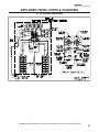
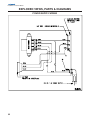
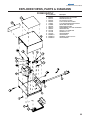
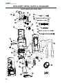
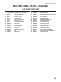
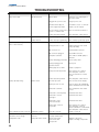
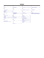
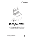
1
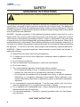
FlexTower Series 8, 12 and 16 Flavor Beverage Dispensers INSTALLATION & SERVICE GUIDE Part Number 020000747 Manitowoc Beverage Equipment 2100 Future Drive Sellersburg, IN 47172-1868 Tel: 812.246.7000, 800.367.4233 Fax: 812.246.9922 www.manitowocbeverage.com In accordance with our policy of continuous product development and improvement, this information is subject to change at any time without notice. March 23, 2007 REV 0 FOREWORD Manitowoc Beverage Equipment (MBE) developed this manual as a reference guide for the owner/ operator, service agent, and installer of this equipment. Please read this manual before installation or operation of the machine. A qualified service technician should perform installation and startup of this equipment. Consult the Troubleshooting Guide within this manual for service assistance. If you cannot correct the service problem, call your MBE Service Agent or Distributor. Always have your model and serial number available when you call. Your Service Agent ___________________________________________________________________ Service Agent Telephone Number ______________________________________________________ Your Local MBE Distributor ___________________________________________________________ Distributor Telephone Number _________________________________________________________ Model Number ______________________________________________________________________ Serial Number _______________________________________________________________________ Installation Date _____________________________________________________________________ UNPACKING AND INSPECTION Note: The unit was thoroughly inspected before leaving the factory. Any damage or irregularities should be noted at the time of delivery. WARRANTY INFORMATION Consult your local MBE Distributor for terms and conditions of your warranty. Your warranty specifically excludes all beverage valve brixing, general adjustments, cleaning, accessories, and related servicing. Your warranty card must be returned to Manitowoc Beverage Equipment to activate the warranty on this equipment. If a warranty card is not returned, the warranty period can begin when the equipment leaves the MBE factory. No equipment may be returned to Manitowoc Beverage Equipment without a written Return Materials Authorization (RMA). Equipment returned without an RMA will be refused at MBE’s dock and returned to the sender at the sender’s expense. Please contact your local MBE distributor for return procedures. TABLE OF CONTENTS FOREWORD ........................................................................................................ 2 UNPACKING AND INSPECTION ......................................................................... 2 WARRANTY INFORMATION ............................................................................... 2 SAFETY ............................................................................................................... 5 IMPORTANT SAFETY INSTRUCTIONS ........................................................................... 5 CARBON DIOXIDE WARNING ......................................................................................... 5 QUALIFIED SERVICE PERSONNEL ................................................................................ 5 SHIPPING, STORAGE, AND RELOCATION ..................................................................... 5 INSTALLATION WARNING .............................................................................................. 5 ADDITIONAL WARNINGS ................................................................................................ 5 GROUNDING IN STRUCTIONS ........................................................................................ 6 INSTALLATION .................................................................................................... 7 SURVEY ........................................................................................................................... 7 COMPONENTS SHIPPED WITH FLEXTOWER ............................................................... 7 CONNECTORS ................................................................................................................. 7 ESSENTIAL TOOLS ......................................................................................................... 7 FOOTPRINT ..................................................................................................................... 8 INSTALLATION PROCEDURE ......................................................................................... 9 PRECHILL COIL RETROFIT KIT & ACCESSORY MATRIX ............................................ 10 PRECHILL COIL RETROFIT KIT ..................................................................................... 11 RECIRCULATION LINES AND PUMP ............................................................................ 13 BRIXING PROCEDURE .................................................................................................. 16 FLEXTOWER WATER RECIRCULATION PUMP FLOW ................................................ 17 FLEXTOWER WATER CHILLER FLOW ......................................................................... 17 FT-8 PLUMBING DIAGRAM ........................................................................................... 18 FT-12 PLUMBING DIAGRAM ......................................................................................... 18 FT-16 PLUMBING DIAGRAM ......................................................................................... 19 OPERATION ...................................................................................................... 20 BASIC FUNCTIONS ....................................................................................................... 20 SPECIFICATIONS .......................................................................................................... 21 SERIAL PLATE ............................................................................................................... 21 PROGRAMMING MODES .............................................................................................. 22 TABLE OF CONTENTS USER MAINTENANCE ...................................................................................... 25 PREVENTATIVE MAINTENANCE .................................................................................. 25 DAILY CLEANING .......................................................................................................... 25 BEVERAGE SYSTEM CLEANING ................................................................................. 27 BAG-IN-BOX SYSTEM ................................................................................................... 27 EXPLODED VIEWS, PARTS & DIAGRAMS ..................................................... 29 FT-8 WIRING DIAGRAM ................................................................................................. 29 FT-12 WIRING DIAGRAM ............................................................................................... 30 FT-16 WIRING DIAGRAM ............................................................................................... 31 POWER SUPPLY WIRING .............................................................................................. 32 POWER SUPPLY ............................................................................................................ 33 FLEXTOWER EXPLODED VIEW.................................................................................... 34 FLEXTOWER PARTS LIST ............................................................................................ 35 TROUBLESHOOTING ....................................................................................... 36 INDEX................................................................................................................. 39 Installation and Service Manual SAFETY IMPORTANT SAFETY INSTRUCTIONS Carefully read all safety messages in this manual. Learn how to operate the FlexTower unit properly. Do not allow anyone to operate the unit without proper training and keep it in proper working condition. Unauthorized modifications to the FlexTower may impair function and/or safety and affect the life of the unit. CARBON DIOXIDE WARNING DANGER: Carbon Dioxide (CO2) displaces oxygen. Exposure to a high concentration of CO2 gas causes tremors, which are followed rapidly by loss of consciousness and suffocation. If a CO2 gas leak is suspected, particularly in a small area, immediately ventilate the area before repairing the leak. CO2 lines and pumps should not be installed in an enclosed space. An enclosed space can be a cooler or small room or closet. This may include convenience stores with glass door self serve coolers. If you suspect CO2 may build up in an area, venting of the B-I-B pumps and / or CO2 monitors should be utilized. QUALIFIED SERVICE PERSONNEL WARNING: Only trained and certified electrical and plumbing technicians should service this unit. All wiring and plumbing must conform to national and local codes. SHIPPING, STORAGE, AND RELOCATION CAUTION: Before shipping, storing, or relocating this unit, syrup systems must be sanitized. After sanitizing, all liquids (sanitizing solution and water) must be purged from the unit. A freezing environment causes residual sanitizing solution or water remaining inside the unit to freeze, resulting in damage to internal components. INSTALLATION WARNING WARNING: The splash panel must remain in place for installation because the splash panel provides structural integrity to the unit. Do not remove the splash panel until after the unit is installed. ADDITIONAL WARNINGS Installation and start-up of this equipment should be done by a qualified service technician. Operation, maintenance, and cleaning information in this manual are provided for the user/operator of the equipment. Save these instructions. 5 Installation and Service Manual SAFETY GROUNDING IN STRUCTIONS WARNING: Risk of electrical shock. Connect to a properly grounded outlet only. This appliance must be grounded. In the event of malfunction or breakdown, grounding provides a path of least resistance for electric current to reduce the risk of electric shock. This appliance is equipped with a cord having an equipment-grounding conductor and a grounding plug. The plug must be plugged into an appropriate outlet that is properly installed and grounded in accordance with all local codes and ordinances. DANGER – Improper connection of the equipment-grounding conductor can result in a risk of electric shock. The conductor with insulation having an outer surface that is green with or without yellow stripes is the equipment grounding conductor. If repair or replacement of the cord or plug is necessary, do not connect the equipment-grounding conductor to a live terminal. Check with a qualified electrician or serviceman if the grounding instructions are not completely understood, or if in doubt as to whether the appliance is properly grounded. Do not modify the plug provided with the appliance – if it will not fit the outlet, have a proper outlet installed by a qualified electrician. WARNING – When using electric appliances, basic precautions should always be followed, including the following: a) Read all the instructions before using the appliance. b) To reduce he risk of injury, close supervision is necessary when an appliance is used near children. c) Do not contact moving parts. d) Only use attachments recommended or sold by the manufacturer. e) Do not use outdoors. f) For a cord-connected appliance, the following shall be included: • Do not unplug by pulling on cord. To unplug, grasp the plug, not the cord. • Unplug from outlet when not in use and before servicing or cleaning. • Do not operate any appliance with a damaged cord or plug, or after the appliance malfunctions or is dropped or damaged in any manner. Return appliance to the nearest authorized service facility for examination, repair, or electrical or mechanical adjustment. g) For a permanently connected appliance – Turn the power switch to the off position when the appliance is not in use and before servicing or cleaning. h) For an appliance with a replaceable lamp – always unplug before replacing the lamp. Replace the bulb with the same type. i) For a grounded appliance – Connect to a properly grounded outlet only. See Grounding Instructions. SAVE THESE INSTRUCTIONS 6 Installation and Service Manual INSTALLATION SURVEY Prior to installation, a location survey is highly recommended to assure there is sufficient room for the FlexTower on the counter, for the BIB rack in the back room, and room to route the beverage tubing from the BIB rack. If an ice drink dispenser heat exchanger is used, assure that the ice drink dispenser is in close proximity to the FlexTower area so the heat exchanger can be easily routed to the tower to provide cold water for the finished beverages. Other methods of cooling the water are available. Contact your Manitowoc Beverage Equipment distributor for details. Assure that a 115 Volt, 15 amp electrical outlet is available to provide power for the FlexTower and the water pump. A separate outlet is recommended for each component Assure that a ¾”( 2 cm) water line with a shut off valve is available in close proximity to the FlexTower. Water treatment is highly recommended to assure a quality finished beverage. Minimum water pressure is 40 PSI (2.75 BAR) dynamic and maximum is 80 PSI (5.5 BAR) static. COMPONENTS SHIPPED WITH FLEXTOWER With unit: • • • If location uses heat exchanger, kit consisting of: Water recirculation pump with power cord and insulated tubing. Four (4) bolt/nut sets for securing FlexTower to most countertops. Template for mounting hardware locations. This template is part of the shipping carton. DO NOT DISCARD CARTON UNTIL TEMPLATE HAS BEEN REMOVED. • • heat exchanger supplementary installation instructions CONNECTORS Syrup should be available on site location at the time of installation to avoid delays and costly return trips to finish the installation. It will be necessary to determine the type of BIB connector used with the syrups. Use the following part numbers when ordering additional kits or replacement parts. P37SBBKHN (Coca Cola) QCD-II (General Bottler) PCS1 (Pepsi) ESSENTIAL TOOLS • • • Tubing Cutters Oetiker pliers Phillips and slotted screwdriver • • • Power drill Six (6) inch adjustable wrench Tape Measure NOTE: The installer is responsible for compliance with all federal, state, and local laws and regulations applying to electrical and plumbing requirements in the installation and operation of the FlexTower and any associated accessories. NOTE: It may be necessary to cut the countertop to provide access for syrup and water lines. It is recommended to route lines from below rather than from the back if possible. 7 Installation and Service Manual INSTALLATION FOOTPRINT The FlexTower must be secured to the countertop using the four (4) holes provided in the base of the unit and using the hardware provided. Follow customer guidelines for placement of the unit or approximately 10 inches (25.4 cm) from the edge of the counter. A mounting template is provided which is printed on the shipping carton. NOTE: DO NOT DISCARD SHIPPING CARTON UNTIL MOUNTING TEMPLATE IS REMOVED. Also see the Footprint below. CAUTION: Cutting the countertop may decrease its strength. Counter should be braced to support the dispenser countertop weight plus ice storage capacity and weight of icemaker, if applicable. 8 Installation and Service Manual INSTALLATION INSTALLATION PROCEDURE • • • • • Assure that 16 bags of syrup are available at location. Coordinate this with the store manager. Manitowoc Beverage Equipment does not supply syrup. Carefully unpack FlexTower and inspect for damage. If damage is noted, file freight claim with carrier. Remove mounting template from shipping carton for use in positioning FlexTower on counter and drilling holes for mounting. Check to assure that all installation components shipped with FlexTower are in the package. Check backroom components to assure that all are with shipment. Removable Rivet 1. Determine type of heat exchanger to be used to cool finished beverage water and install according to instructions provided with heat exchanger. 2. In the back room, determine location for BIB rack and install. 3. Route C02 supply to C02 regulator. Do not turn on C02 pressure at this time. 4. Using the template provided, determine location where the FlexTower is to be installed. Note: FlexTower should be located next to the ice dispenser. Cut out the tubing access area and drill the required holes for the mounting hardware. 5. Remove splash shield, cosmetic nozzle, and grid from unit. Remove the removable rivets from the bottom left and right sides of the front cover, lift up and pull the front cover forward and off. 6. Label and route the two (2) eight (8) line conduit between BIB rack and area and FlexTower location. 7. Install water pump and plumb to water source and to heat exchanger. 8. Route water lines from pump to FlexTower location. 9. Connect water lines to tee fitting supplying water valve. (See Plumbing Diagram) 10. Connect drain. (See Drainage Options) 11. Using the FlexTower Plumbing Diagram, connect syrup lines to syrup valves assuring that proper syrup Cosmetic Nozzle line is connected to the correct valve. 12. Place FlexTower in final location, apply sealant to base of unit and secure to counter with hardware provided. Splash Shield 13. Place flavor labels on touch pad if required. 14. In back room, position BIB syrups on BIB rack. Grid 15. Attach BIB connector to syrup line from syrup pump Drain pan to BIB outlet. 16. Turn on C02 supply and regulate to 40 PSI (2.75 BAR) for non carbonated beverages. 17. At FlexTower, purge syrup lines. 18. Turn on water supply to FlexTower and purge water line. 19. Brix valves then ensure the syrup injections shroud assembly is firmly clipped into place and all vinyl syrup tubes are firmly seated into their corresponding port on the syrup injection shroud assembly. (See Brixing Procedure) 20. Replace front cover and reinstall removable rivets, then replace the cosmetic nozzle, splash shield and grid. 21. Install any merchandising materials shipped with FlexTower. 22. Instruct store personnel in operation and maintenance of the FlexTower and back room items. 9 Installation and Service Manual INSTALLATION PRECHILL COIL RETROFIT KIT & ACCESSORY MATRIX Cooling Coil and Left Side Replacement Strip Lid Panel Kits Ice Beverage Dispenser Model (See Note 1) Strip Lid Kit (See Note 1) Part Number For Kit MDH-302 MDH-302 MDH-302 MDH-302 MDH-302 MDH-302 MDH-402 MDH-402 MDH-402 MDH-402 MDH-402 MDH-402 MDH-402 MDH-402 IB4 IB5 SL3 SL4 SL7 SL11 SL5 SL6 SL9 IB6 IB7 IB8 IB9 SL8 020001176 020001176 020001177 020001178 020001179 020001180 020001246 020001247 020001248 020001249 020001249 020001250 020001250 020001251 Accessory Kits Flex Tower Model Description Kit Part Number FT-16, 12 and 8 FT-16, 12 and 8 Recirc Pump & Line Kit Install Kit 020000783 020001070 BIB Racks Flex Tower Model Description BIB Rack Part Number FT-16 FT-12 FT-8 Preassembled 16 Box BIB Rack Preassembled 12 Box BIB Rack Preassembled 8 Box BIB Rack AR-6W3H16F-VERT-QCD AR-6W2H12F-VERT-QCD AR-6W2H8F-VERT-QCD NOTES 1) When ordering cooling coil and left side replacement strip lid panel kits the following information is needed. a) Servend ice beverage dispenser model number the cooling coil will be installed inside of. b) The ice machine(s) model number(s) installed on top of the Servend ice beverage dispenser. c) The information is needed in order to ship kit with the correct left side replacement strip lid panel(s) and cooling coil. 10 Installation and Service Manual INSTALLATION PRECHILL COIL RETROFIT KIT 1A 1A 2A 2B 1B FIGURE 1 3F 3B 3G 3E 3E 3C 3A 3D FIGURE 2 3.00 inches 4C 4A 4D 4B 1. Disconnect or shut of power, water supply to ice maker or makers (1A) and power supply to ice beverage dispenser (1B) (See Figure 1). Failure to do so may cause electrical shock or injury. 2. Ice beverage dispensers (1B) equipped with one or two ice makers (1A) and a strip lid kit (2A and 2B) will need partial or total removal of items in order to gain access to the ice storage bin for cooling coil heat exchanger installation (See Figures 1 and 2).If applicable on Servend 302 and 402 ice beverage dispensers remove ice maker (1A), strip lid panels (2A) and support brackets (2B) from the left side of unit only to access the left side ice storage bin (See Figure 1). Keep all removed components and ice maker or makers in a safe place for reinstallation later. 3. Remove all ice from the ice storage bin (3A) of dispenser in which the cooling coil heat exchange will be installed (See Figure 2). On Servend 302 and 402 ice beverage dispensers remove ice from left side ice storage bin only. Remove the paddlewheel pin or pins (3B), agitator bar (3C), double –D coupling [where applicable], bin liner (3D) the four knurled bin liner screws (3E), paddlewheel (3F), paddlewheel area bushing [where applicable] and paddle wheel area (3G) from ice storage bin (3A) (See Figure 2). On Servend 302 and 402 ice beverage dispensers remove the components previously listed from the left side ice storage bin only. Keep all removed components in a safe place for reinstallation later. 4. Part of the rubberized bin gasket (4A) will need to be trimmed away [3.00 inches] from the back left side corner of the ice beverage dispenser (4B) as shown (See Figure 3). 5. Use a 3.00 inch piece of the black adhesive foam gasket included kit to seal for sanitation reasons over the previously trimmed 3.00 inch area (4C). Remove protective covering from black adhesive foam gasket before adhering to surfaces of ice beverage dispenser (See Figure 3). 6. Clean the left inside corner of ice storage bin (4D) from top to bottom and 6.00 inches to the left and right with isopropyl alcohol or cleaning solution (See Figure 3). FIGURE 3 11 Installation and Service Manual INSTALLATION PRECHILL COIL RETROFIT KIT 6A 5B 5C 5A FIGURE 4 7A 7E 7B 7D 7C FIGURE 5 8D 8E 8C 8A 8B FIGURE 6 12 7. Place the cooling coil heat exchanger (5A) into the previously cleared and cleaned ice storage bin (5B) as shown (See Figure 4). Be sure the coil is resting flat on coldplate (5C) of the ice beverage dispenser (See Figure 5). The inlet and outlet fittings (8E) of the cooling coil heat exchanger will exit over previously trimmed 3.00 inch open area (4C) of the rubberized bin gasket (4A) in the back left corner of the ice beverage dispenser (4B) (See Figures 3 and 6). The inlet and outlet fittings (8E) of coil should be visible from the back of the ice beverage dispenser (8C) (See Figure 6). 8. Remove protective covering from adhesive tape on back of the plastic cover (6A) that is factory installed on the cooling coil heat exchanger (6B) (See Figure 6). Place plastic cover (6A) snuggly into previously cleaned left inside corner of ice beverage dispenser (8C) flush with the top of the ice storage bin (8D) as shown (See Figures 4 and 6). 9. Reinstall the paddle wheel area (3G), paddlewheel area bushing [where applicable] and paddlewheel (3F) in the ice storage bin (3A) that components were previously removed from (See Figure 2). 10. Install the plastic cover support bracket (7A) under the left side of the bin liner (7B) when reinstalling the bin liner (7B) and the four knurled bin liner screws (3E) as shown (See Figures 2 and 5). 11. Reinstall the double –D coupling [where applicable], agitator bar (7C) and paddlewheel pin or pins (7D) in the ice storage bin (7E) that components were previously removed from (See Figure 5). 12. If applicable reinstall strip lid kit or components previously removed for access to install cooling coil heat exchanger in the ice beverage dispenser. The original left side strip lid panel (2A) and support brace (2B) [where applicable] will be replaced by a new left side strip lid panel and support brace included with some but not all kits (See Figure 1). 13. Reinstall the ice maker or makers (1A) using the proper install procedures on the ice beverage dispenser (1B) (See Figure 1). 14. Place label (8A) [Part No.5011948] near existing serial tag (8B) of ice beverage dispenser (8C) (See Figure 6). 15. Reconnect or turn on the water, power supplies to the ice beverage dispenser and ice maker or makers. Check for leaks and make sure the ice beverage dispenser, ice maker or makers operate normally before placing units back into general service. Installation and Service Manual INSTALLATION RECIRCULATION LINES AND PUMP PARTS INCLUDED IN KIT NO: 020000783 Qty. 1 3 1 10 6ft Description Part Number Recirculation pump/w/fittings Line insulated beverage Instructions Recirculation lines Clamp Otiker 15.7 Tape Cork Insulation 020000780 020000781 020000782 15.7-706R RM051120 1B 1C 1F 1E 1D 1G 1A FIGURE 1 2B FIGURE 2 3A 3B 2A 1. If required secure recirculation pump (1A) to counter or under counter that unit is installed on (See Figure 1). Run insulated beverage line (1B) from the barded pump outlet fitting up to the right barbed cooling coil inlet (2A) on back of dispenser and secure both ends of line to the barbed fittings with otiker clamps (See Figures 1 and 2). Connect another insulated beverage line to left barbed cooling coil outlet (2B) on back of dispenser and secure line to barbed fitting with otiker clamp (See Figure 2). 2. Wrap cork tape insulation around the barbed inlets (3A) and insulated beverage lines (3B) as shown (See Figure 3). Installation of cork tape must be done properly to prevent condensation and temperature gain of circulating water. 3. Route insulated beverage line from the cooling coil outlet (2B) up through either the back or bottom of tower (4A) as shown (See Figures 2 and 4). Route insulated beverage line through left side hole in the valve mount plate (4B) as shown (See Figure 4). Connect insulated beverage line to left side of barb fitting (4C) and secure line to barbed fitting with otiker clamp (See Figure 4). Connect the last insulated beverage line to right side of barbed fitting (4E) and secure line to barbed fitting with otiker clamp (See Figure 4). Wrap fitting and insulated beverage lines (4D) with cork tape insulation (See Figure 4). Installation of cork tape must be done properly to prevent condensation and temperature gain of circulating water. 4. Chiller Installations: When using a refrigerated chiller (5A) for cooling plain water supplied to tower the recirculation pump can be mounted to the exterior cabinet of chiller (See Figure 5).. 5. Chiller Installations: Attach insulated beverage line (1B) to the pump outlet fitting and secure with otiker clamp. Then run insulated line (1B) to the plain water coil inlet (5B) of the chiller (5A). Secure line to the coil inlet (5B) of the chiller (5A) mechanically. If applicable us an otiker clamp (See Figures 1 and 5). 6. Chiller Installations: Connect another insulated beverage line to the plain water coil outlet (5C) of the chiller (5A). Secure line to the coil outlet (5C) of the chiller (5A) mechanically. If applicable us an otiker clamp (See Figure 5). FIGURE 3 13 Installation and Service Manual INSTALLATION RECIRCULATION LINES AND PUMP 4C 7. Chiller Installations: Route insulated beverage line from the coil outlet (5C) up through either the back or bottom of tower (4A) as shown (See Figures 4 and 5). Route insulated beverage line through left side hole in the valve mount plate (4B) as shown (See Figure 4). Connect insulated beverage line to left side of barb fitting (4C) and secure line to barbed fitting with otiker clamp (See Figure 4). Connect the last insulated beverage line to right side of barbed fitting (4E) and secure line to barbed fitting with otiker clamp (See Figure 4). Wrap fitting and insulated beverage lines (4D) with cork tape insulation (See Figure 4). Installation of cork tape must be done properly to prevent condensation and temperature gain of circulating water. 4E 4D 4F 4B 4A FIGURE 4 5C FIGURE 5 14 5A 5B Cooling Coil and Chiller Common Instructions 8. Route insulated beverage line through right side hole in the valve mount plate (4F) as shown (See Figure 4). Route insulated beverage line either through back or bottom of tower (See Figure 4). 9. Connect insulated beverage line from right side of tower to pump inlet barbed fitting (1C) and secure with otiker clamp (See Figure 1). Connect potable water supply line (3/8 ID line size) to barbed pump connection (1D) and secure line with otiker clamp (See Figure 1). After all line connections have been made ensure potable water supply is flowing or turned on and check for leaks. If no leaks are present dispense water through the tower to purge any trapped air from the recirculation loop and pump. Connect power supply cord (1E) from recirculation pump (1A) to receptacle (1F) on the power supply (1G) or to a separate power outlet or receptacle (See Figure 1). Installation and Service Manual INSTALLATION DRAINAGE OPTIONS The drains for FLEXTOWER connect to the drain pan Option One Option Two Drainage through the bottom of the unit: Drainage through the back of the unit: Straight Fitting Radiator Clamp 90° Elbow Fitting Flexble Tubing Radiator Clamp Flexble Tubing Back of unit Openings for beverage and drain lines. Rear Access for Drain Hose & Beverage Lines 15 Installation and Service Manual INSTALLATION BRIXING PROCEDURE NOTE: This procedure is for flavors requiring 5:1 water to syrup ratio. Control Board Program Button LED Water Valve Syrup Injection Shroud OZ C C C C OZ 225 8 200 7 175 6 45 150 5 125 4.75 1 30 25 20 15 11:1 11:1 Touchpad Selection Areas 100 4 3 75 2 50 50 1 5:1 40 35 10 5 5:1 R ATIO R ATIO Funnel and 5:1 Brix Cup 1. Connect water and syrup to system and purge lines at both the syrup and water valves to assure that syrup and water are available at the valves. 2. If the front panel is on the front of the unit, remove it to gain access to the syrup and water valves. In order to remove the front panel, the grid, splash shield, and cosmetic nozzle must be removed first. 3. Use a standard brix cup with a 5:1 ratio for the procedure. 4. Locate the control board. 5. Press the program button until 1 is displayed on the control board LED display. See the Control Board Programming pages. 6. Press the program button until the LED displays 3. This is the water adjustment mode on the circuit board. 7. Place the brix cup with the water side of the cup under the nozzle of the water valve (located in the center of the unit. 8. Press any touchpad selection area and the valve will dispense water for 3 seconds. 9. Check the output volume of water. The correct volume should be 6 oz. If adjustment is needed to attain this volume, adjust the water side adjustment screw on the water valve until 6 oz. (177 ml) is present. 10. Repeat the above steps until the water valve is brixed and dispensing 6 oz. (177 ml) of water in 3 seconds. 16 11. Press the program button on the control board until the LED displays 4. 12. Note that each flavor has a corresponding port on the syrup injection shroud. 13. Use the funnel provided with the FT unit to direct the syrup into the brix cup. Place the funnel under the syrup injection shroud and the outlet of the funnel into the syrup side of the brix cup. 14. Press any touchpad area and the corresponding syrup will be dispensed for 3 seconds. 15. Syrup should be even with the 6 oz. (177 ml) water mark on the cup or at the 35cc mark on the syrup side of the brix cup. 16. Check each syrup position and adjust syrup on the corresponding valve as necessary. A plumbing label is located on the unit showing the position of each valve and syrup port. See the Plumbing Diagram page. 17. Return the control board to the dispense position by pressing the program button for 3 seconds or until the LED displays 0. 18. Check each flavor to assure that both syrup and water are dispensing properly and that the flavor that corresponds to the flavor label is being dispensed. 19. Replace front panel, cosmetic nozzle, splash shield, and grid. Installation and Service Manual INSTALLATION FLEXTOWER WATER RECIRCULATION PUMP FLOW FLEXTOWER WATER CHILLER FLOW Plumbing and Wiring Diagrams can be located inside the front cover of the FlexTower. 17 Installation and Service Manual INSTALLATION FT-8 PLUMBING DIAGRAM FT-12 PLUMBING DIAGRAM Plumbing and Wiring Diagrams can be located inside the front cover of the FlexTower. 18 Installation and Service Manual INSTALLATION FT-16 PLUMBING DIAGRAM Plumbing and Wiring Diagrams can be located inside the front cover of the FlexTower. 19 Installation and Service Manual OPERATION BASIC FUNCTIONS The FlexTower is a free standing unit which is designed for counter top merchandising and dispensing of non carbonated finished beverages and flavoring syrups in any combination up to 16 flavors. Dispensing is accomplished by supplying syrup to an electric valve via a BIB pump and routing the syrup to a common dispense point at an electric valve centrally located to supply plain water. Plain water for the non carbonated beverages is cooled by circulation through a cooling coil placed in an adjacent ice dispenser bin and pumped by a circulation pump located under the counter or by remote cooling units. 1. Pressing a labeled finished beverage selection area on the touch pad activates the electric syrup valve to deliver syrup and the water valve to provide water for the desired finished beverage. 2. Pressing a labeled flavor enhancer syrup only selection area on the touch pad activates the electric valve to provide the desired flavored syrup in a predetermined quantity. Water is not dispensed with flavor enhancer only flavored syrup. 3. The touchpads can be changed from a non carbonated finished beverage to flavor enhancer syrup only through programming on the control board. The FlexTower is shipped with the touchpads programmed in the non carbonated beverage mode by default. 4. A dedicated 120 VAC, 15 ampere circuit is required to provide power to the power supply's transformer with an output of 24 VAC for the electric valves, 120 VAC, 8 ampere circuit, and to power a cold water recirculation pump. The power supply has a 120 VAC outlet to provide power for the cold water recirculation pump. 5. A plain water supply capable of delivering 100 GPH (378.5 liters/hr) with a minimum dynamic water pressure of 40 PSI (2.75 BAR) and a maximum static water pressure of 80 PSI (5.5 BAR) is required to provide water for the non carbonated beverages. Water treatment is highly recommended to assure a quality finished beverage. A drain pan connection is provided at the rear of the drain pan and must be routed to a drain in conformance with plumbing codes. (See Drainage Options) The back room items (ordered separately) consist of: 1. Bag-in-box rack capable of holding sixteen flavor boxes. 5. Two (2) – eight (8) line, .250 (.635 cm) beverage barrier tubing conduit – 100 ft. (30.5 meters). 2. 0 – 100 PSI (0 – 6.9 BAR) Secondary regulator. For non carbonated beverages delivery pressure is 40 PSI (2.75 BAR). For flavor syrup only, delivery pressure is 40 PSI (2.75 BAR). 6. Additional .250 (.635 cm) tubing for C02 supply. 3. Beverage pumps and connecting tubing. 4. Bag-in-box connectors as required by syrup manufacturer. 20 7. Oetiker clamps and fittings. 8. 2.5 gallon (9.5 liter) bag-in-box syrup containers with a dip tube to allow multidirectional placement on the rack is suggested. This will allow for a 6-6-4 bag placement on the rack. This product is supplied by customer or syrup manufacturer and is not available through Manitowoc Beverage Equipment. Installation and Service Manual OPERATION SPECIFICATIONS SERIAL PLATE Serial Plate Serial Plate 21 Installation and Service Manual OPERATION PROGRAMMING MODES LED Display Program Button CONTROL BOARD RUN OR DISPENSE MODE (Control Board LED Displays 0) For finished drink, press and hold any labeled finished drink touchpad area to manually dispense a finished noncarbonated drink (all touchpad areas are defaulted from factor to manual dispense mode). For flavor adder, press any labeled flavor adder touchpad area and a one shot stored timed dispense will occur (dispense time of flavor adder can be changed in program mode 2). TO ACCESS PROGRAMMING MODES To enter programming modes, press and hold control board program button for a minimum of 3 seconds. Control board LED displays a number (1) for manual dispense mode. To select another programming mode, press and release the control board program button once to enter the next programming mode. Repeat pressing and releasing the control board program button until desired program mode is entered. TO EXIT PROGRAMMING MODES To exit programming modes and to save programming mode changes, press and hold control board program button for a minimum of 3 seconds. Control board LED displays (0) for run or dispense mode. MANUAL DISPENSE MODE (Finished Noncarbonated Drink Dispensed) Once in program mode (1), control board LED displays (1). Press any touchpad selection area two times in less than three seconds and selection area LED lights will blink twice to indicate the touchpad area has been programmed for manual dispense. The procedure can be repeated for other touchpad selection areas needing programmed for manual dispense. After all designated touchpad areas have been programmed for manual dispense either enter another program mode or exit the programming modes, which will save programming mode changes. THE 6 PROGRAMMING MODES ON FLEXTOWER CONTROL BOARD Program Mode 1= Manual Dispense Mode Program Mode 2= Timed Dispense Mode or Flavor Adder Mode Program Mode 3= Water Calibration Mode Program Mode 4= Syrup Calibration Mode Program Mode 5= Touchpad Configuration Mode Program Mode 6= Touchpad LED Light Sequencing Mode 22 Installation and Service Manual OPERATION PROGRAMMING MODES LED Display Program Button TIMED DISPENSE MODE (Flavor Adder Dispensed) Once in program mode (2), control board LED displays (2). Press any touchpad selection area three times in less than three seconds and selection area LED lights will blink three times to indicate the touchpad area has been programmed for timed dispense. Then the first and last touchpad selection areas will illuminate, which will allow increasing the timed dispense cycle by .2 seconds each press of the last illuminated touchpad selection area or decreasing the timed dispense cycle by .2 seconds each press of the first illuminated touchpad selection area. To program another touchpad area for timed dispense press and release the control board program button to reset the timed dispense programming mode, first and last touchpad areas are no longer illuminated. Repeat procedures for programming timed dispense for other designated touchpad selection areas. After all designated touchpad areas have been programmed for timed dispense either enter another program mode or exit the programming modes, which will save programming mode changes. WATER CALIBRATION MODE Once in program mode (3), control board LED displays (3). Press any touchpad selection area and the noncarbonated water valve will dispense for three seconds in order to brix the valve. The procedure can be repeated as many times as necessary in order to brix the noncarbonated water valve. After the water valve has been brixed either enter another program mode or exit the programming modes, which will save programming mode changes. SYRUP CALIBRATION MODE Once in program mode (4), control board LED displays (4). Press any touchpad selection area and the associated syrup valve circuit will dispense for three seconds in order to brix the syrup valve circuit. The procedure can be repeated as many times as necessary in order to brix all syrup valve circuits. After all syrup valve circuits have been brixed either enter another program mode or exit the programming modes, which will save programming mode changes. 23 Installation and Service Manual OPERATION PROGRAMMING MODES 8 Section Area Touchpad TOUCHPAD CONFIGURATION MODE Once in program mode (5), control board LED displays (5). Press the first and last touchpad selection areas on both touchpads. The touchpad LED lights sequence through all the touchpad selection areas indicating the touchpad has been configured. After configuring both touchpads either enter another program mode or exit the programming modes, which will save programming mode changes. TOUCHPAD LED LIGHT SEQUENCING MODE (8 Selection Area Touchpad) Once in program mode (6), control board LED displays (6). Press the first touchpad selection areas on either touchpad for clockwise LED light sequencing. The touchpad LED lights sequence clockwise through all the touchpad selection areas indicating the touchpad has been configured for clockwise LED light sequencing. Or press the second touchpad selection areas on either touchpad for counterclockwise LED light sequencing. The touchpad LED lights sequence counterclockwise through all the touchpad selection areas indicating the touchpad has been configured for counterclockwise LED light sequencing. Or press the third touchpad selection area on either touchpad to turn off LED light sequencing. The third touchpad area LED lights illuminate for 3 seconds then turn off indicating the touchpad has been configured for LED light sequencing off mode. After configuring the LED light sequencing for touchpads either enter another program mode or exit the programming modes, which will save programming mode changes. 24 4 Section Area Touchpad TOUCHPAD LED LIGHT SEQUENCING MODE (4 Selection Area Touchpad) Once in program mode (6), control board LED displays (6). Press the first touchpad selection areas on either touchpad for upward LED light sequencing. The touchpad LED lights sequence upward through all the touchpad selection areas indicating the touchpad has been configured for upward LED light sequencing. Or press the second touchpad selection areas on either touchpad for downward LED light sequencing. The touchpad LED lights sequence downward through all the touchpad selection areas indicating the touchpad has been configured for downward LED light sequencing. Or press the third touchpad selection area on either touchpad to turn off LED light sequencing. The third touchpad area LED lights illuminate for 3 seconds then turn off indicating the touchpad has been configured for LED light sequencing off mode. After configuring the LED light sequencing for touchpads either enter another program mode or exit the programming modes, which will save programming mode changes. Installation and Service Manual USER MAINTENANCE PREVENTATIVE MAINTENANCE NOTICE: Under normal operating conditions, periodic cleaning is minimal but absolutely necessary. Preventative maintenance is a vital part of keeping your FlexTower in top condition. Following the guidelines below will assist you in continued trouble free operation of your unit. Contact MBE at 1-800-367-4233 for more information about our ProActive Maintenance Program. 1. Conduct daily maintenance of the machine. 3. Perform periodic maintenance and sanitizing of beverage system. 2. Perform monthly maintenance of the machine. DAILY CLEANING CAUTION: Use only warm soapy water to clean the exterior of the unit. Do not use solvents or other cleaning agents. Do not pour hot coffee into the drain pan. Pouring hot coffee down the drain pan can eventually crack the drain pan, especially if the drain pan is cold or contains ice. CLEANING CHECKLIST Check CO2 supply. If CO2 supply is low, an arrow on the primary regulator gauge will point to a shaded area that reads “Low CO2” or “Change CO2 Cylinder.” Check syrup supply. Clean drain pan, grid, splash shield, cosmetic nozzle, water valve nozzle and syrup injection shroud assembly. • • • Scheduled cleaning must be in compliance with local health codes. The FlexTower must not be cleaned with a water jet. This cleaning schedule is a recommendation. Daily clean the following: Cosmetic Nozzle Splash Shield • • • • • • Cosmetic Nozzle Grid Drain pan Splash Shield Syrup Shroud Assembly Water Valve Nozzle - Diffuser Assembly Grid Drain pan 25 Installation and Service Manual USER MAINTENANCE DAILY CLEANING Cleaning the grid, splash shield and drain pan Splash Shield Switch 1. Turn off the on/off rocker switch located on left side of the unit. 2. Lift the grid and splash shield to remove them from the drain pan. 3. Using mild soap, warm water and a clean cloth, wipe the drain pan. Then, rinse with clean, warm water. Allow plenty of warm (not hot) water to run down the drain of the drain pan, to remove syrup residue that can clog the drain opening. 4. Wash the grid and splash shield, then rinse with clean water. Place the grid and splash shield back in the drain pan. 5. Wash all exterior surfaces of the unit with warm water and a clean cloth. Wipe again with a clean, dry cloth. Cleaning the water valve nozzle and diffuser, cosmetic nozzle and syrup injection shroud assembly 6. Remove the cosmetic nozzle, and then remove nozzle-diffuser assembly from water valve. 7. Rinse the cosmetic nozzle and water valve nozzlediffuser assembly with warm, clean water. 8. Clean water valve nozzle-diffuser assembly with soapy water and a soft bristle brush. 9. Clean the cosmetic nozzle, underside of the water valve and the inside of the syrup injection shroud assembly with warm, soapy water. Rinse with clean warm towel. 10. Replace water valve nozzle-diffuser assembly and cosmetic nozzle. 11. Turn on the on/off rocker switch located on left side 26 Installation and Service Manual USER MAINTENANCE BEVERAGE SYSTEM CLEANING NOTICE: When changing syrup boxes, immerse connector in warm water (100° F, 38° C - maximum temperature) to remove syrup residue. • RECOMMENDED SANITATION INTERVAL IS EVERY 90 DAYS Sanitize the beverage system at initial start-up as well as regularly scheduled cleaning. The drain pan must be in place under soda valves, to carry away detergent and sanitizing agents that will be flushed through valves. BAG-IN-BOX SYSTEM The procedure below is for the sanitation of one syrup circuit at a time. Repeat to sanitize additional circuits. You will need the following items to clean and sanitize the Bag-in-Box (BIB) beverage system: • • • • 1. 2. 3. 4. 5. 6. 7. 8. 9. 10. Three (3) clean buckets Plastic brush or soft cloth Mild detergent Unscented bleach (5% Na CL O) or Commercial sanitizer • Bag-In-Box bag connector Prepare the following in the buckets: • Bucket 1 - warm to hot tap water for rinsing. • Bucket 2 - mild detergent and warm to hot water. • Bucket 3 - mix a solution of unscented bleach (5% Na CL O) or commercial sanitizer and warm to hot water. Mixture should supply 200 PPM available chlorine (1/2 oz. bleach to 1 gallon water). Disconnect the “syrup-line side” of the bag-in-box connector. Rinse connector with warm tap water. Connect syrup connector to BIB connector and immerse both into Bucket 1. A “bag-side” connector can be created by cutting the connector from an empty disposable syrup bag. Draw rinse water through system until clean water is dispensed. Connect Bucket 2 to system. Draw detergent solution through system until solution is dispensed. Repeat steps 2-7 until all syrup circuits contain detergent solution. Allow detergent solution to remain in the system for 5 minutes. Connect Bucket 3 to system. 27 Installation and Service Manual USER MAINTENANCE BAG-IN-BOX SYSTEM 11. Draw sanitizing solution through system until solution is dispensed. 12. Repeat step 11 until all syrup circuits contain sanitizer solution. 13. Allow sanitizer solution to remain in system for 15 minutes. 14. Remove cosmetic nozzle and the water valve nozzlediffuser assembly. 15. Scrub water valve nozzle-diffuser assembly, the cosmetic nozzle and the inside of the syrup shroud assembly with a soft cloth and the detergent solution. 16. Soak cosmetic nozzle and the water valve nozzlediffuser assembly in sanitizer for 15 minutes. 17. Rise clean the water valve nozzle-diffuser assembly, 28 the cosmetic nozzle and the inside of the syrup shroud assembly with a soft cloth and warm clean water. 18. Replace the water valve nozzle-diffuser assembly. 19. Connect Bucket 1 to system. 20. Draw rinse water through system until no presence of sanitizer is detected. 21. Rinse clean the inside of the syrup injection shroud again with clean warm water and a soft cloth. 22. Replace cosmetic nozzle. 23. Attach syrup connectors to BIB’s. 24. Draw syrup through system until only syrup is dispensed. 25. Discard first 2 drinks. Installation and Service Manual EXPLODED VIEWS, PARTS & DIAGRAMS FT-8 WIRING DIAGRAM Plumbing and Wiring Diagrams can be located inside the front cover of the FlexTower 29 Installation and Service Manual EXPLODED VIEWS, PARTS & DIAGRAMS FT-12 WIRING DIAGRAM Plumbing and Wiring Diagrams can be located inside the front cover of the FlexTower 30 Installation and Service Manual EXPLODED VIEWS, PARTS & DIAGRAMS FT-16 WIRING DIAGRAM Plumbing and Wiring Diagrams can be located inside the front cover of the FlexTower 31 Installation and Service Manual EXPLODED VIEWS, PARTS & DIAGRAMS POWER SUPPLY WIRING 32 Installation and Service Manual EXPLODED VIEWS, PARTS & DIAGRAMS POWER SUPPLY No Part Number Description 1 2 3 4 5 6 7 8 9 10 11 12 13 14 15 SCREW 6-32X3/8" SS PH RHMS WASHER STAR #8 SS TIP 1/8IN TINY PLASTIC CLIP PLASTIC WIRE & CORD PLUG HEYCO CORD STRAIN RELIEF COVER BOX ELECTRICAL BASE ELECRICAL BOX TRANSFORMER 75VA 120V w/BREAKER CORD ELECTRIC SCR 8-32 X 1/2 GRND ZINC SCREW 8-32 X 1/2 LABEL WARNING LABEL WIRING HARNESS 120 VOLT SUPPLY LABEL GROUND 0900904 0901915 0904504 0905403 1200301 4340006 5007848 5008229 5008642 5011936 5011940 5012610 020000571 020000741 020000752 33 Installation and Service Manual EXPLODED VIEWS, PARTS & DIAGRAMS FLEXTOWER EXPLODED VIEW 34 Installation and Service Manual EXPLODED VIEWS, PARTS & DIAGRAMS FLEXTOWER PARTS LIST No. Part Number Description No. Part Number Description 1 2 3 4 5 6 7 8 9 10 11 12 13 14 15 16 17 18 19 20 21 FLOMATIC VALVE BLOCK .380 FLOMATIC SYRUP / SYRUP VALVE STANDOFF 7/16 HIGH SWITCH SPST 16A 3/4HP SCREW 8-32 X 1/4" PH PS CLAMP 3/8" CABLE SCREW 6-32X3/8" SS PH RHMS SCREW 8-32 X 1/2 SCR 10-24X1-1/4 SELF TAP SCR 8-32 x 1/4" PH PS PLATE BASE REAR COVER PANEL FRONT PANEL REAR SHIELD SPLASH BASE W/ DRAIN PAN NOZZEL COSMETIC PUSH PLATE PLATE VALVE BRACKET UPPER VALVE Grid BOARD LIGHTS 22 23 24 25 26 27 28 29 30 31 33 34 35 36 37 38 39 40 41 42 43 BRACKET LIGHTS DECAL METAL FRONT MEDALLION SYRUP INJECTION SHROUD WITH PORTS TOUCH PAD 4 AREA TOUCH PAD 8 AREA DECAL METAL NOZZLE BOARD CIRCUIT MAIN WATER RECIRCULATION LINE RIVET PLAS REMOVABLE VALVE FLOMATIC 464 PC HARNESS WATER VALVE HARNESS SYRUP VALVE HARNESS TOUCHPAD ACTIVATION HARNESS TOUCHPAD LED HARNESS CIRCUIT BOARD POWER HARNESS LED LIGHTING HARNESS 24 VOLT SUPPLY SUPPLY 120 VOLT 60 HZ POWER FITTING DOUBLE 0-RING 45 DEGREES TUBING 1/4 OD X 13IN 380-Q 424-CSY-D22MD 00212539 00804437 0901430 5009971 5011935 5011940 5011953 5012081 5012154 020000299 020000300 020000308 020000309 020000348 020000470 020000471 020000472 020000515 020000537 020000568 020000569 020000570 020000621 020000622 020000623 020000636 020000712 020000767 020000970 464-GP-P36 020000641 020000642 020000640 020000643 020000645 020000644 020000615 020000742 5013687 020000770 35 Installation and Service Manual TROUBLESHOOTING C O N D IT IO N IN V E S T IG AT IO N CHECK C O R R E C T IO N N o p o w e r a t unit. E le c tric a l c irc uit O n/o ff s w itc h S w itc h to o n p o s itio n/re p la c e d e fe c tive s w itc h P lug g e d into p o w e r s o urce P lug in p o w e r c o rd C irc uit b re a k e r trip p e d D e te rm ine s o urc e o f o ve rlo a d P o w e r s up p ly ino p e ra tive R e p la c e p o w e r s up p ly 2 4 vo lt co nne c to r fro m p o w e r s o urc e to c o ntro l b o a rd C he c k c o nne c tio n/co nne c to r C o ntro l b o a rd ino p e ra tive C he c k /re p la c e c o ntro l b o a rd L ig ht m o d ule s Ino p e ra tive lig ht m o d ule s R e p la c e m o d ule s C o ntro l b o a rd C o ntro l b o a rd p ro g ra m m ing C he c k a nd p ro g ra m /re p ro g ra m S yrup c irc uit S yrup s up p ly d e p le te d R e p le ntis h s yrup s up p ly S yrup p re s s ure to o lo w A d jus t s yrup p re s s ure to 4 0 P S I (2 .7 5 B A R ) B IB c o nne c to r o ff R e a tta ch B IB c o nne c to r B IB c o nne c to r p lug g e d C le a n B IB c o nne c to r S yrup line re s tric te d C he c k line fro m B IB p um p to M F T-1 6 S yrup o utle t p lug g e d a t va lve C le a n s yrup o utle t S yrup p o rt p lug g e d a t inje c tio n s hro ud C le a n p o rt O utle t syrup line o ff va lve R e p la c e s yrup line S yrup s o le no id ino p e ra tive C he c k p o w e r to s o le no id C he c k /re p la c e s o le no id C he c k c o nne c tio n to c o ntro l b o a rd C o ntro l b o a rd ino p e ra tive C he c k /re p la c e c o ntro l b o a rd N o w a te r p re s sure C he c k s o urc e w a te r s up p ly W a te r p re s s ure to o lo w H a ve lo c a tio n c he c k p lum b ing a nd /o r insta ll w a te r b o o ste r unit W a te r line re s tric te d C he c k w a te r line fro m w a te r s o urc e W a te r line s o ff w a te r p um p R e a tta ch w a te r line s W a te r line s o ff he a t e xc ha ng e r R e a tta ch w a te r line s W a te r line s o ff te e c o nne c tio n in unit R e a tta ch w a te r line s W a te r va lve s o le no id ino p e ra tive C he c k p o w e r to s o le no id C he c k /re p la c e s o le no id C heck connection to control board C he c k /re p la c e c o ntro l b o a rd B o a rd /b ra c k e t lig hts ino p e ra tive W a te r o nly d is p e nsing (o ne o r m o re fla vo rs) S yrup o nly d is p e ns ing W a te r c ircuit N o isy syrup /w a te r va lve so le no id S yrup /w a te r va lve s D e fe c tive s o le no id R e p la c e s o le no id F inis he d d rink ta s te to o s w e e t/no t s w e e t e no ug h F inis he d d rink b rix inc o rre c t C he ck b rix ra tio a s s p e c ifie d b y s yrup m a nufa c ture r B rix finis he d d rink S yrup /w a te r le a k s S yrup a nd w a te r c irc uits C he ck w a te r/s yrup c o nne c tio ns a nd c o m p o ne nts Tig hte n c o nne c tio ns R e p la c e le a k ing c o m p o ne nts 36 INDEX B F P T brixing ....................................... 2 FOREWORD ............................ 2 Parts 29, 30, 31, 32, 33, 34, 35 TROUBLESHOOTING ............ 36 C G Q U Grid ......................................... 25 Qualified Service Personnel ..... 5 UNPACKING ............................. 2 I R W INSPECTION ............................ 2 Installation Date ........................ 2 irregularities .............................. 2 Relocation ................................. 5 return procedures ..................... 2 Warning ..................................... 5 WARRANTY INFORMATION ... 2 water-to-syrup ratio. See brixing Carbon Dioxide ......................... CAUTION .................................. Cleaning .................................... CO2 ........................................... CO2 monitors ............................ 5 9 2 4 4 D S Daily Cleaning ......................... 25 damage ..................................... 2 delivery ...................................... 2 Diagrams ..... 29, 30, 31, 32, 33 distributor .................................. 2 M E N Exploded Views 29, 30, 31, 32, 33, 34, 35 nozzle ...................................... 28 MBE .......................................... 2 Model Number .......................... 2 modifications ............................. 5 O Operation .................................. 5 SAFETY ............................... 5, sanitizing ................................... Serial Number ........................... service assistance .................... Service Personnel ..................... Shipping .................................... Shipping, Storage, Relocation .. splash panel .............................. start-up ...................................... Storage ..................................... 6 4 2 2 5 5 5 4 5 5 Manitowoc Beverage Equipment 2100 Future Drive Sellersburg, IN 47172-1868 Tel: 812.246.7000, 800.367.4233 Fax: 812.246.9922 www.manitowocbeverage.com In accordance with our policy of continuous product development and improvement, this information is subject to change at any time without notice. 020000747 March 23, 2007 REV 0