1
UDA-8705A
Analog Utility Distribution Amplifier
User Manual
Part Number: UDA-8705A-OM
Version: 1.1
UDA-8705A • Analog Utility Distribution Amplifier User Manual
•
•
•
Sierra Video Part Number: UDA-8705A-OM
Document Issue: 1.1
Printed in United States.
The information contained in this User Manual is subject to change without notice or obligation.
Copyright
© 2010 Sierra Video. All rights reserved.
Contents of this publication may not be reproduced in any form without the written permission of
Sierra Video. Reproduction or reverse engineering of copyrighted software is prohibited.
Notice
The material in this manual is furnished for informational use only. It is subject to change without
notice and should not be construed as a commitment by Sierra Video. Sierra Video assumes no
responsibility or liability for errors or inaccuracies that may appear in this manual.
Trademarks
•
•
•
•
•
is a registered trademark of Ross Video.
is a registered trademark of Sierra Video.
DashBoard Control System™ is a registered trademark of Ross Video.
Ross, ROSS, ROSS , and MLE are registered trademarks of Ross Video.
All other product names and any registered and unregistered trademarks mentioned in this
manual are used for identification purposes only and remain the exclusive property of
their respective owners.
Important Regulatory and Safety Notices
Before using this product and any associated equipment, refer to the “Important Safety Instructions”
listed below so as to avoid personnel injury and to prevent product damage.
Products may require specific equipment, and /or installation procedures be carried out to satisfy
certain regulatory compliance requirements. Notices have been included in this publication to call
attention to these Specific requirements.
Symbol Meanings
This symbol on the equipment refers you to important operating and maintenance
(servicing) instructions within the Product Manual Documentation. Failure to heed
this information may present a major risk of damage or injury to persons or
equipment.
The symbol with the word “Warning” within the equipment manual indicates a
potentially hazardous situation, which if not avoided, could result in death or serious
injury.
Warning
The symbol with the word “Caution” within the equipment manual indicates a
potentially hazardous situation, which if not avoided, may result in minor or
moderate injury. It may also be used to alert against unsafe practices.
Caution
The symbol with the word “Notice” within the equipment manual indicates a
situation, which if not avoided, may result in major or minor equipment damage or a
situation which could place the equipment in a non-compliant operating state.
Notice
This symbol is used to alert the user that an electrical or electronic device or
assembly is susceptible to damage from an ESD event.
ESD
Susceptibility
Important Safety Instructions
Caution
This product is intended to be a component product of the openGear 8300 series
frame. Refer to the openGear 8300 series frame User Manual for important safety
instructions regarding the proper installation and safe operation of the frame as well
as it’s component products.
Warning
Certain parts of this equipment namely the power supply area still present a safety
hazard, with the power switch in the OFF position. To avoid electrical shock,
disconnect all A/C power cords from the chassis' rear appliance connectors before
servicing this area.
Warning
Service barriers within this product are intended to protect the operator and service
personnel from hazardous voltages. For continued safety, replace all barriers after
any servicing.
This product contains safety critical parts, which if incorrectly replaced may present
a risk of fire or electrical shock. Components contained within the product’s power
supplies and power supply area, are not intended to be customer serviced and should
be returned to the factory for repair.
To reduce the risk of fire, replacement fuses must be the same type and rating.
Only use attachments/accessories specified by the manufacturer.
EMC Notices
US FCC Part 15
This equipment has been tested and found to comply with the limits for a class A Digital device,
pursuant to part 15 of the FCC Rules. These limits are designed to provide reasonable protection
against harmful interference when the equipment is operated in a commercial environment. This
equipment generates, uses, and can radiate radio frequency energy and, if not installed and used in
accordance with the instruction manual, may cause harmful interference to radio communications.
Operation of this equipment in a residential area is likely to cause harmful interference in which case
users will be required to correct the interference at their own expense.
Changes or modifications to this equipment not expressly approved by Sierra Video.
could void the user’s authority to operate this equipment.
Notice
CANADA
This Class “A” digital apparatus complies with Canadian ICES-003.
Cet appareil numerique de classe “A” est conforme à la norme NMB-003 du Canada.
EUROPE
This equipment is in compliance with the essential requirements and other relevant provisions of CE
Directive 93/68/EEC.
INTERNATIONAL
This equipment has been tested to CISPR 22:1997 along with amendments A1:2000 and A2:2002 and
found to comply with the limits for a Class A Digital device.
This is a Class A product. In domestic environments this product may cause radio
interference in which case the user may have to take adequate measures.
Notice
Maintenance/User Serviceable Parts
Routine maintenance to this openGear product is not required. This product contains no user
serviceable parts. If the module does not appear to be working properly, please contact Technical
Support using the numbers listed under the “Contact Us” section on the last page of this manual. All
openGear products are covered by a generous 5-year warranty and will be repaired without charge for
materials or labor within this period. Refer to the “Warranty and Repair Policy” section in this manual
for details.
Environmental Information
The equipment that you purchased required the extraction and use of natural resources for its
production. It may contain hazardous substances that could impact health and the environment.
To avoid the potential release of those substances into the environment and to diminish the need for the
extraction of natural resources, Sierra Videoencourages you to use the appropriate take-back systems.
These systems will reuse or recycle most of the materials from your end-of-life equipment in an
environmentally friendly and health conscious manner.
The crossed-out wheeled bin symbol invites you to use these systems.
If you need more information on the collection, reuse, and recycling systems, please contact your local
or regional waste administration.
You can also contact Sierra Videofor more information on the environmental performances of our
products.
Contents
Introduction
1-1
In This Chapter ....................................................................................................................... 1-1
A Word of Thanks .................................................................................................... 1-1
Overview .................................................................................................................. 1-1
Functional Block Diagrams ...................................................................................... 1-2
Features .................................................................................................................... 1-3
Documentation Terms .............................................................................................. 1-3
Installation and Setup
2-1
In This Chapter ....................................................................................................................... 2-1
Static Discharge ........................................................................................................ 2-1
Unpacking................................................................................................................. 2-1
Rear Module Installation (Optional) ......................................................................... 2-2
Board Installation ..................................................................................................... 2-3
BNC Labels .............................................................................................................. 2-3
Cable Connections .................................................................................................... 2-3
User Controls
3-1
In This Chapter ....................................................................................................................... 3-1
Jumper Locations...................................................................................................... 3-2
LEDs......................................................................................................................... 3-2
Button Controls ........................................................................................................ 3-3
Control and Monitoring
4-1
In This Chapter ....................................................................................................................... 4-1
DashBoard Control System ...................................................................................... 4-1
SNMP Monitoring and Control ................................................................................ 4-3
Specifications
5-1
In This Chapter ....................................................................................................................... 5-1
Service Information
6-1
In This Chapter ....................................................................................................................... 6-1
Troubleshooting Checklist ........................................................................................ 6-1
Power LED Conditions ............................................................................................. 6-2
Bootload Button ....................................................................................................... 6-2
Warranty and Repair Policy...................................................................................... 6-2
Ordering Information
7-1
UDA-8705A and Related Products ......................................................................................... 7-1
UDA-8705A User Manual (Rev. 1.1)
Contents • i
ii • Contents
UDA-8705A User Manual (Rev. 1.1)
Introduction
In This Chapter
This chapter contains the following sections:
•
A Word of Thanks
•
Overview
•
Functional Block Diagrams
•
Features
•
Documentation Terms
A Word of Thanks
Congratulations on choosing the openGear UDA-8705A Analog Utility Distribution Amplifier. The
UDA-8705A is part of a full line of Digital Products within the openGear Terminal Equipment family
of products, backed by Sierra Video's experience in engineering and design expertise.
You will be pleased at how easily your new UDA-8705A fits into your overall working environment.
Equally pleasing is the product quality, reliability and functionality. Thank you for joining the group of
worldwide satisfied Sierra Video customers!
Should you have a question pertaining to the installation or operation of your UDA-8705A, please
contact us at the numbers listed on the back cover of this manual. Our technical support staff is always
available for consultation, training, or service.
Overview
The UDA-8705A is an analog general-purpose distribution amplifier. It is very useful in digital systems
when there is a requirement for the distribution of a few analog signals, such as a color black reference.
The UDA-8705A is a general-purpose amplifier for use in the distribution of analog SD-video, Trilevel sync or AES3id audio. It is intended for use in situations where cable equalization and differential
input are not needed, and clamping is not required. Gain is adjustable over a wide range of ±3dB.
This amplifier is DC-coupled and will faithfully provide all aspects of a video input signal to eight
identical output copies with very low distortion. The use of new generation integrated circuits and
innovative engineering has resulted in excellent performance combined with economy.
The UDA-8705A is designed for use in the openGear DFR-8300 series frames.
UDA-8705A User Manual (Rev. 1.1)
Introduction • 1-1
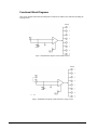
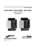
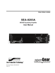
Functional Block Diagrams
This section includes functional block diagrams to illustrate the UDA-8705A functions including the
looping feature.
Figure 1. Simplified Block Diagram of UDA-8705A Functions
Figure 2. Simplified Block Diagram of UDA-8705A with Looping Function
1-2 • Introduction
UDA-8705A User Manual (Rev. 1.1)
Features
The following features make the UDA-8705A the best solution for general analog distribution:
•
8 analog video outputs
•
DC Coupled
•
Wide adjustable gain range of ±3dB
•
Low distortion
•
Excellent isolation between outputs
•
Power to each card is individually fused
•
Fits DFR-8310 and DFR-8320 series frames
•
Fully compliant with openGear specifications
•
5-year transferable warranty
Documentation Terms
The following terms are used throughout this guide:
•
“Frame” refers to the DFR-8300 series frame that houses the UDA-8705A card, as
well as any openGear frames.
•
All references to the DFR-8300 series frame includes versions of the 10-slot (DFR8310) and 20-slot (DFR-8320) frames and any available options.
•
“Operator” and “User” both refer to the person who uses the UDA-8705A.
•
“Board” and “Card” both refer to the UDA-8705A unit itself, including all
components and switches.
•
“System” and “Video system” both refer to the mix of interconnected production
and terminal equipment in which the UDA-8705A operates.
UDA-8705A User Manual (Rev. 1.1)
Introduction • 1-3
1-4 • Introduction
UDA-8705A User Manual (Rev. 1.1)
Installation and Setup
In This Chapter
This chapter contains the following sections:
•
Static Discharge
•
Unpacking
•
Rear Module Installation (Optional)
•
Board Installation
•
BNC Labels
•
Cable Connections
Static Discharge
Whenever handling the UDA-8705A and other related equipment, please observe all static discharge
precautions as described in the following note:
ESD
Susceptibility
Static discharge can cause serious damage to sensitive
semiconductor devices. Avoid handling circuit boards in high
static environments such as carpeted areas, and when wearing
synthetic fiber clothing. Always exercise proper grounding
precautions when working on circuit boards and related
equipment.
Unpacking
Unpack each UDA-8705A you received from the shipping container, and check the contents against the
packing list to ensure that all items are included. If any items are missing or damaged, contact your
openGear sales representative or Sierra Videodirectly.
UDA-8705A User Manual (Rev. 1.1)
Installation and Setup • 2-1
Rear Module Installation (Optional)
The UDA-8705A is compatible with the DFR-8310 and DFR-8320 series frames. The procedure for
installing the Rear Module in your openGear frame is the same regardless of the frame or module used.
However, a different module is required depending on the openGear frame you are using.
Rear Modules for the UDA-8705A
The Rear Module for the UDA-8705A depends on the openGear frame you are installing the card into.
•
DFR-8310 series frames — When installing the UDA-8705A in the DFR-8310 series
frames, the R1-8705 or R1L-8705 Rear Modules are required. The UDA-8705A is
also compatible with the DFR-8310-BNC frame.
•
DFR-8320 series frames —When installing the UDA-8705A in the DFR-8320 series
frames, the Split Rear Module (R2S-8705) or Full Rear Modules (R2-8705 or R2L8705) are required.
Installing the Rear Module
If you received a Rear Module with your UDA-8705A, you will need to install the module in your
DFR-8300 series frame before you can install the UDA-8705A in the frame, or connect cables to the
slot you have chosen for the UDA-8705A. Skip this section if you are installing the UDA-8705A in a
DFR-8310-BNC frame, or the Rear Module is already installed.
Use the following procedure to install the Rear Module in a DFR-8300 series frame:
1.
Refer to the DFR-8300 series frame User Manual, to ensure that the frame is properly
installed according to instructions.
2.
On the rear of the frame, locate the card frame slot.
3.
Remove the Blank Plate from the rear of the slot you have chosen for the UDA8705A installation. If there is no Blank Plate installed, proceed to the next step.
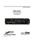
4.
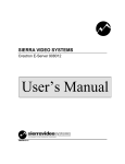
As shown in Figure 3, seat the bottom of the rear module in the seating slot at the
base of the frame’s back plane.
Figure 3. Rear Module Installation in a DFR-8310 Series Frame (UDA-8705A not shown)
2-2 • Installation and Setup
UDA-8705A User Manual (Rev. 1.1)
5.
Align the top hole of the rear module with the screw hole on the top edge of the
frame back plane.
6.
Using a Phillips driver and the supplied screw, fasten the rear module to the back
plane. Do not over tighten.
7.
Ensure proper frame cooling and ventilation by having all rear frame slots covered
with Rear Module or blank metal plates. If you need blanks, refer to the chapter,
“Ordering Information” in your DFR-8300 series frame User Manual, and contact
your Sierra Video sales representative.
This completes the procedure for installing the Rear Module in a DFR-8300 series frame.
Board Installation
Use the following procedure to install the UDA-8705A in a DFR-8300 series frame:
1.
Refer to the User Manual of your DFR-8300 series frame to ensure that the frame is
properly installed.
2.
After selecting the desired frame installation slot, hold the UDA-8705A card by the
edges and carefully align the card edges with the slots in the frame.
3.
Fully insert the card into the frame until the rear connection plugs are properly seated
on the midplane and rear modules.
This completes the procedure for installing the UDA-8705A in an DFR-8300 series frame.
BNC Labels
Affix the supplied BNC label, as per the included instructions, to the BNC area on the rear of the rack
frame.
Cable Connections
This section provides instructions for connecting cables to the installed Rear Modules on your DFR8300 series frame backplane.
Connections for the DFR-8310 Series Frames
In the DFR-8310 series frames, the UDA-8705A occupies one slot and provides eight analog outputs.
The input of the UDA-8705A can be terminated on the card depending on the rear module used. It is
not necessary to terminate unused outputs.
In the DFR-8310 series frames, the UDA-8705A may be used with the following Rear Modules:
•
R1-8705 Full Rear Module — Each card provides eight outputs. The input must be
terminated on the UDA-8705A using JP1. Refer to Figure 4 for cable connections.
•
R1L-8705 Full Rear Module — Each card provides eight outputs and one looping
output. If the input is looped on the rear module to another device, JP1 must be set
to LOOP. If looping is not used, either set JP1 to TERM, or terminate the input
externally at BNC 2. Refer to Figure 5 for cable connections.
UDA-8705A User Manual (Rev. 1.1)
Installation and Setup • 2-3
Figure 4. Cable Connections for the R1-8705 and
R2-8705 Rear Modules
Figure 5. Cable Connections for the R1L-8705 and
R2L-8705 Rear Modules
Connections for the DFR-8320 Series Frames
In the DFR-8320 series frames, the UDA-8705A may be used with the following Rear Modules:
•
R2-8705 Full Rear Module — Each card occupies two slots and provides eight
outputs. The input must be terminated on the card by setting JP1 to TERM. Refer to
Figure 4 for cable connections.
•
R2L-8705 Full Rear Module with Looping — Each card occupies two slots and
provides eight outputs plus one looping output. If the input is looped on the rear
module to another device, JP1 must be set to LOOP. If looping is not used, either
set JP1 to TERM, or terminate the input externally at BNC2. Refer to Figure 5.
•
R2S-8705 Split Rear Module — Each card occupies one slot and provides four
outputs. Note that each Rear Module provides connections for two cards. Ensure the
input is terminated on the card at JP1. Refer to Figure 6 for cable connections.
Figure 6. Cable Connections for the R2S-8705 Rear Module
2-4 • Installation and Setup
UDA-8705A User Manual (Rev. 1.1)
User Controls
In This Chapter
This chapter includes the following sections:
•
Jumper Locations
•
LEDs
•
Button Controls
UDA-8705A User Manual (Rev. 1.1)
User Controls • 3-1
Jumper Locations
The following sections describe the jumpers on the UDA-8705A.
Figure 7. Jumper Locations
JP1 — Local Termination Jumper
The position of JP2 selects an optional 75ohm termination on the input of the UDA-8705A card.
Select one of the following options:
•
TERM — Install the jumper in this position to terminate the input signal on this
card. This is the default setting.
•
LOOP — Install the jumper in this position to leave the input unterminated. For
example, configure this setting if you wish to loop the signal to another device.
RV2 — Gain Adjustment
The rotation of RV2 adjusts the Gain level of the UDA-8705A and provides a gain range of +/- 3dB.
LEDs
The following sections describe the UDA-8705A LEDs. Refer to Figure 8 for LED locations.
Figure 8. LED Locations
3-2 • User Controls
UDA-8705A User Manual (Rev. 1.1)
PWR (Power) LED
The PWR LED indicates the overall operating status of the UDA-8705A. This LED displays the
following conditions:
•
Green — The card is operating normally.
•
Flashing Green — The card requires a software upgrade.
•
Red — The card is not operational. Refer to the chapter, “Service Information” for
details on this condition.
Input Signal Present LEDs
The Input Signal Present LEDs indicates the status of the analog input. This group of LEDs display
the following conditions:
Note
•
VIDEO — If the VIDEO LED is lit, a valid analog video input signal is present on
BNC 1.
•
AES/OTHER — If the AES/OTHER LED is lit, a valid AES signal, or some other
analog signal, is present on the input. The signal must be greater than 0.5Vp-p.
Slowly changing, or small, amplitude signals will pass through the card, but the
LEDs may be unlit. In this case, it is recommended to disable the Notify on
Input Loss option via DashBoard. Note that the Input Signal Present threshold
is set to assume a level of 1Vp-p.
Button Controls
The following sections describe the UDA-8705A buttons. Refer to Figure 8 for button location.
SW1 — Bootload Button
This button is used for factory service in the unlikely event of a complete card failure. The Bootload
process is further described in the chapter, “Service Information”, of this manual.
UDA-8705A User Manual (Rev. 1.1)
User Controls • 3-3
3-4 • User Controls
UDA-8705A User Manual (Rev. 1.1)
Control and Monitoring
In This Chapter
This section provides a detailed explanation on using remote control functions with your UDA-8705A.
The following topics are discussed:
•
DashBoard Control System
•
SNMP Monitoring and Control
DashBoard Control System
The DashBoard Control System™ enables you to monitor and control openGear frames and controller
cards from a computer. DashBoard communicates with other cards in the DFR-8300 series frame
through the MFC-8310-N Network controller card. This card is required in order to use DashBoard to
configure the UDA-8705A.
The DashBoard software and manual can be downloaded from the Sierra Video website.
Using the Menus
You must first install the DashBoard Control System on your computer. Refer to the DashBoard User
Manual for software installation procedures and using the DashBoard interface.
The following tables and sections describe the menus, items, and parameters available from the
DashBoard Control System for the UDA-8705A.
UDA-8705A User Manual (Rev. 1.1)
Control and Monitoring • 4-1
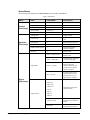
Status Menus
The following table summarizes the Status Menu options available in DashBoard.
Table 1. Status Menus
Menu
Product
(Read-only)
Hardware
(Read-only)
Item
Parameters
Product
UDA-8705A
Supplier
Sierra Video
Board Rev
##
Serial Number
######-###
Software Rev
#.##
Voltage (mV)
#
Supply Voltage
Current (mA)
#
Current consumption of
card
Rear Module
#
Rear module for the card
CPU Headroom
#
Processing power available
RAM Available (bytes)
#
On-board processing
memory available
EE Bank
#
Storage count
Green – Video Present
Card is passing valid
analog video
Green – AES/Other
Card is passing AES audio
or other analog signal
Green – No input
No input present or the
signal is below the
detection threshold. The
Notify on Loss of Input
option is disabled.
Red – No input
No input present or the
signal is below 0.5V p-p.
The Notify on Loss of
Input option is enabled.
Signal Status
Signal
(Read-only)
Description
480i 59.94
720p 59.94
1080i 59.94
1080p 29.97
576i 50
Indicates the valid video
format detected
720p 50
Signal Format
1080i 50
1080p 25
4-2 • Control and Monitoring
Unknown Video
Indicates a video signal is
present but is an unknown
format
AES/Other
Indicates an audio or other
analog signal is detected
UDA-8705A User Manual (Rev. 1.1)
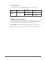
Configuration Menus
The following table summarizes the Configuration Menu options available in DashBoard.
Table 2. Configuration Menus
Menu
Item
Setup
Notify on Loss of
Input
*
Parameters
Description
Checkbox is selected*
DashBoard reports the loss
of input
Checkbox is unselected
DashBoard does not report
the loss of input
This is the default setting.
SNMP Monitoring and Control
The MFC-8310-N Network Controller card in the DFR-8300 series frame provides optional support for
remote monitoring and control of your frame and UDA-8705A using Simple Network Management
Protocol (SNMP), which is compatible with many third-party monitoring and control tools.
Refer to your UDA-8705A Management Information Base (MIB) file for a breakdown of SNMP
controls on this card.
Refer to your DFR-8300 series frame user manual for additional information on SNMP Monitoring and
Control.
UDA-8705A User Manual (Rev. 1.1)
Control and Monitoring • 4-3
4-4 • Control and Monitoring
UDA-8705A User Manual (Rev. 1.1)
Specifications
In This Chapter
This chapter includes the Technical Specifications for the UDA-8705A.
UDA-8705A User Manual (Rev. 1.1)
Specifications • 5-1
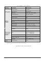
Table 3. UDA-8705A Technical Specifications
Category
Parameter
Specification
Number of Inputs
1 (Looping*)
Input Impedance
75Ω terminating
Return Loss
43dB to 5MHz, 35dB to 20MHz
Nominal Signal Level
1Vpp (video, AES-3id)
Number Of Outputs
8
Output Impedance
75Ω
Output Return Loss
45dB to 5MHz, 41dB to 20MHz
Output Isolation
51dB to 5MHz, 40dB to 20MHz
DC Offset
<30mV
Frequency Response
±0.08dB to 10MHz, ±0.2dB to 20MHz
Differential Phase
<0.1˚ in NTSC, <0.3˚ in PAL
Differential Gain
<0.1% in NTSC, <0.1% in PAL
RMS Noise (unweighted)
68dB
Gain Range
±3dB
Gain Stability
<0.2% per 10˚C
Performance
Delay
7ns (9˚ @ 3.58MHz) NTSC
7ns (11˚ @ 4.43MHz) PAL
(all outputs
loaded)
Chrominance-to-Luminance Delay
<2.0ns
Line Rate Window Tilt
<0.1%
Field Rate Window Tile
<0.1%
Bandwidth
-3dB @ 56MHz Typical
Total Power Draw
<1.5W
Analog Input
Analog
Outputs
Power
*Looping only available with the R1L-8705 or R2L-8705 Rear Modules.
Specifications are subject to change without notice
5-2 • Specifications
UDA-8705A User Manual (Rev. 1.1)
Service Information
In This Chapter
This chapter contains the following sections:
•
Troubleshooting Checklist
•
Power LED Conditions
•
Bootload Button
•
Warranty and Repair Policy
Troubleshooting Checklist
Routine maintenance to this openGear product is not required. In the event of problems with your
UDA-8705A, the following basic troubleshooting checklist may help identify the source of the
problem. If the card still does not appear to be working properly after checking all possible causes,
please contact your openGear products distributor, or the Technical Support department at the numbers
listed under the “Contact Us” section at the end of this manual.
1.
Visual Review Performing a quick visual check may reveal many problems, such
as connectors not properly seated or loose cables. Check the card, the frame, and any
associated peripheral equipment for signs of trouble.
2.
Power Check Check the power indicator LED on the distribution frame front
panel for the presence of power. If the power LED is not illuminated, verify that the
power cable is connected to a power source and that power is available at the power
main. Confirm that the power supplies are fully seated in their slots. If the power
LED is still not illuminated, replace the power supply with one that is verified to
work.
3.
Reset the Card in the Frame — Eject the card and re-insert it in the frame.
4.
Check Control Settings — Refer to the Installation and Operation sections of the
manual and verify all user-adjustable component settings.
5.
Input Signal Status Verify that source equipment is operating correctly and that a
valid signal is being supplied.
6.
Output Signal Path Verify that destination equipment is operating correctly and
receiving a valid signal.
7.
Card Exchange Exchanging a suspect card with a card that is known to be
working correctly is an efficient method for localizing problems to individual cards.
UDA-8705A User Manual (Rev. 1.1)
Service Information • 6-1
Power LED Conditions
The top front edge of the module has a Power LED which indicates card status. The Power LED
displays the following conditions:
•
Off no power to the card.
•
Amber the card is running internal diagnostics while powering up.
•
Green normal operation.
•
Flashing Green the card is waiting for a software upgrade.
•
Red solid or flashing means the card is not operational. Reseat card in frame, check
the Rear Module type and connections, or call Sierra Video Technical Support.
Bootload Button
In the unlikely event of a complete card failure, you may be instructed by a Sierra Video Technical
Support specialist to perform a complete software reload on the UDA-8705A. Contact Sierra Video
Technical Support for the latest software load for your card.
Use the following procedure to perform a complete software reload on the card:
1.
Eject the card.
2.
Press and hold the Bootload button, while re-inserting the card into the frame.
3.
Release the button.
The PWR LED will flash GREEN while the card is waiting for a new software load.
If a new software load is not sent to the card within 60 seconds, the card will attempt to
restart with its last operational software load.
This completes the procedure for performing a complete software reload on the card.
Sierra openGear Warranty
A. General
Buyer assumes all responsibility for ascertaining the suitability of Sierra Video Systems (hereinafter "SVS") products for
Buyer's intended use. No product sold by SVS is designed or manufactured for use in any manner or under any
conditions other than those described in SVS's instruction manuals and other printed material for each particular product.
If any product is used or applied in a manner or under conditions not specifically authorized by such written materials or
if any product is used by unqualified or improperly trained personnel, Buyer agrees that SVS shall have no liability of
any kind arising from such use, and Buyer agrees to indemnify and hold SVS harmless from any claims of third parties
arising from such use, and Buyer shall provide SVS with counsel of SVS's choice to defend against such claims.
B. Limited Warranty
1. This warranty applies only to the original purchaser and is non-transferable. This warranty begins on the date of
purchase and will be in effect for five (5) years for new equipment or and for three (3) years for "Factory Refurbished"
equipment. Buyer must obtain a Return Material Authorization ("RMA") number from SVS prior to returning a product
for repair. If, in SVS' sole discretion, the product is found to be defective during the term of this warranty, SVS will at its
option: (a) provide free replacement parts, and/or (b) repair the unit at an SVS facility. During the warranty period, SVS
will make every reasonable effort to support critical emergencies by supplying no-cost loan equipment while the
defective unit is being repaired. SVS will provide replacement parts and/or factory service at no charge. Buyer bears the
6-2 • Service Information
UDA-8705A User Manual (Rev. 1.1)
cost of shipping products returned to SVS under this warranty. SVS will bear the cost of shipping repaired products or
replacement parts to the Buyer.
This limited warranty shall not apply to any of SVS's goods which have been altered or which shall have been subjected
to misuse, mishandling, improper storage or negligence. The aforementioned provisions do not extend the original
warranty period of any goods which have been replaced by SVS. This limited warranty shall not apply to any goods not
of SVS's manufacture, Buyer to be entitled only to the warranty set forth in the original manufacturer's limited warranty.
THIS LIMITED WARRANTY IS EXPRESSED IN LIEU OF ALL OTHER WARRANTIES, EXPRESS, IMPLIED
OR STATUTORY, INCLUDING WITHOUT LIMITATION THE IMPLIED WARRANTIES OF
MERCHANTABILITY AND OF FITNESS FOR A PARTICULAR PURPOSE, AND ALL OTHER OBLIGATIONS
OR LIABILITIES ON SVS'S PART.
SVS neither assumes nor authorizes any other person to assume for SVS any other liabilities in connection with the sale
of products of its own manufacture.
2. SVS's liability hereunder on any claim of any kind, except as set forth herein for any loss, injury to person or property
or damage, shall in no case exceed the price allocable to the goods which give rise to such claim.
3. In no event shall SVS be liable for any damages or injuries to person or property if any goods do not meet the
above limited warranty, including, without limitation, incidental expenses or consequential or special damages, except as
set forth in such limited warranty. The foregoing states the exclusive remedy of Buyer and the exclusive liability of SVS
for any breach of the foregoing limited warranty.
C. Cancellation
Except as provided in paragraph B immediately above, all sales are final, and Buyer may cancel this order or return
products only upon written consent of SVS.
D. General
A.
In the event of a breach of any of the terms hereof, the non-breaching party shall be entitled to recover all of its
costs, fees, and expenses, including, without limitation, reasonable attorney's fees, from the breach party incurred as a
result of such breach, regardless of whether or not a suit is actually filed to enforce the terms hereof.
B.
The provision hereof shall be governed by the laws of the State of California (excluding its choice of law
provisions).
C.
The headings are for convenience only and do not limit or amplify the terms and provisions hereof.
D.
In case any one or more of the provisions set forth herein shall be held to be invalid, illegal, or unenforceable in
any respect, the validity, legality, and enforceability of the remaining provisions contained herein shall not in any way be
affected or impaired thereby.
UDA-8705A User Manual (Rev. 1.1)
Service Information • 6-3
E.
No waiver, alteration, or modification of any of the provisions hereof shall be binding unless in writing and
signed by an authorized Officer of SVS.
NOTE:
All products returned to SVS for service must have prior approval. Return authorization requests may be obtained from
your SVS dealer.
In Case of Problems
Should any problem arise with your UDA-8705A, please contact the Sierra Video Technical Support
Department. (Contact information is supplied at the end of this publication.)
A Return Material Authorization number (RMA) will be issued to you, as well as specific shipping
instructions, should you wish our factory to repair your UDA-8705A. If required, a temporary
replacement module will be made available at a nominal charge. Any shipping costs incurred will be
the responsibility of you, the customer. All products shipped to you from Sierra Video will be shipped
collect.
The Sierra Video Technical Support Department will continue to provide advice on any product
manufactured by Sierra Video, beyond the warranty period without charge, for the life of the
equipment.
6-4 • Service Information
UDA-8705A User Manual (Rev. 1.1)
UDA-8705A User Manual (Rev. 1.1)
Service Information • 6-5
Ordering Information
UDA-8705A and Related Products
Your UDA-8705A Analog Utility Distribution Amplifier is a part of the openGear family of products.
Sierra Video offers a full line of openGear terminal equipment including distribution, conversion,
monitoring, synchronizers, encoders, decoders, keyers, switchers, as well as analog audio and video
products.
Standard Equipment
•
UDA-8705A Analog Utility Distribution Amplifier
•
UDA-8705A-OM Analog Utility Distribution Amplifier User Manual
Optional Equipment
•
UDA-8705A-OM Analog Utility Distribution Amplifier User Manual (additional)
•
R1-8705 openGear Rear Module for the DFR-8310 series frames
•
R1L-8705 openGear Rear Module with Looping for the DFR-8310 series frames
•
DFR-8310-N Digital Products Frame and Power Supply with cooling fans, and MFC8310-N card (2RU, holds up to 10 cards)
•
DFR-8320-CNS Digital Products Frame, Power Supply, Cooling Fans, MFC-8310-N,
COMM I/O Module and SNMP-8310 (2RU, holds up to 20 cards)
•
R2-8705 openGear Full Rear Module for the DFR-8320 series frames (10 per frame)
•
R2L-8705 openGear Full Rear Module with Looping for the DFR-8320 series frames (10
per frame)
•
R2S-8705 openGear Split Rear Module for the DFR-8320 series frames (10 per frame)
Please contact your openGear sales representative for a complete list of the available options.
UDA-8705A User Manual (Rev. 1.1)
Ordering Information • 7-1
Contact Us
Contact our friendly and professional support representatives for the following:
•
Name and address of your local dealer
•
Product information and pricing
•
Technical support
•
Upcoming trade show information
PHONE
E-MAIL
POSTAL
SERVICE
General Business Office
and Technical Support
530-478-1000
After-hours Emergency
530-888-3195
Fax
530-478-1105
General Information
Service @sierravideo.com
Technical Support
[email protected]
Sierra Video
104B New Mohawk Rd
Nevada City, CA 95959
Sierra Video
Incorporated
PO Box 2462
Grass Valley, CA 95945
Visit Us
Please visit us at our website for:
•
Company information
•
Related products and full product lines
•
On-line catalog
•
Trade show information
•
News
•
Testimonials