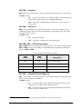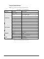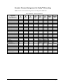
1
Ross Video Limited
DED-8420
Dolby® E/AC-3 Decoder
User Manual
Ross Part Number: 8420DR-004
Issue: 01
DED-8420 • Dolby® E/AC-3 Decoder User Manual
•
•
•
Ross Part Number: 8420DR-004
Document Issue: 01
Printed in Canada.
The information contained in this User Manual is subject to change without notice or obligation.
Copyright
© 2008 Ross Video Limited. All rights reserved.
Contents of this publication may not be reproduced in any form without the written permission of
openGear. Reproduction or reverse engineering of copyrighted software is prohibited.
Notice
The material in this manual is furnished for informational use only. It is subject to change without
notice and should not be construed as a commitment by Ross Video Limited. Ross Video Limited
assumes no responsibility or liability for errors or inaccuracies that may appear in this manual.
Trademarks
•
•
•
•
•
•
is a registered trademark of Ross Video Limited.
is a registered trademark of Ross Video Limited.
DashBoard Control System™ is a trademark of Ross Video Limited.
Ross, ROSS, ROSS ®, and MLE are registered trademarks of Ross Video Limited.
Dolby® is a registered trademark of Dolby Laboratories.
All other product names and any registered and unregistered trademarks mentioned in
this manual are used for identification purposes only and remain the exclusive property
of their respective owners.
Important Regulatory and Safety Notices
Before using this product and any associated equipment, refer to the “Important Safety Instructions”
listed below so as to avoid personnel injury and to prevent product damage.
Products may require specific equipment, and /or installation procedures be carried out to satisfy
certain regulatory compliance requirements. Notices have been included in this publication to call
attention to these Specific requirements.
Symbol Meanings
This symbol on the equipment refers you to important operating and maintenance
(servicing) instructions within the Product Manual Documentation. Failure to heed
this information may present a major risk of damage or injury to persons or
equipment.
Warning
Caution
Notice
The symbol with the word “Warning” within the equipment manual indicates a
potentially hazardous situation, which if not avoided, could result in death or serious
injury.
The symbol with the word “Caution” within the equipment manual indicates a
potentially hazardous situation, which if not avoided, may result in minor or
moderate injury. It may also be used to alert against unsafe practices.
The symbol with the word “Notice” within the equipment manual indicates a
situation, which if not avoided, may result in major or minor equipment damage or a
situation which could place the equipment in a non-compliant operating state.
This symbol is used to alert the user that an electrical or electronic device or
assembly is susceptible to damage from an ESD event.
ESD
Susceptibility
Important Safety Instructions
Caution
This product is intended to be a component product of the openGear 8000 series
frame. Refer to the openGear 8000 series frame User Manual for important safety
instructions regarding the proper installation and safe operation of the frame as well
as it’s component products.
Warning
Certain parts of this equipment namely the power supply area still present a safety
hazard, with the power switch in the OFF position. To avoid electrical shock,
disconnect all A/C power cords from the chassis' rear appliance connectors before
servicing this area.
Warning
Service barriers within this product are intended to protect the operator and service
personnel from hazardous voltages. For continued safety, replace all barriers after
any servicing.
This product contains safety critical parts, which if incorrectly replaced may present
a risk of fire or electrical shock. Components contained within the product’s power
supplies and power supply area, are not intended to be customer serviced and should
be returned to the factory for repair.
To reduce the risk of fire, replacement fuses must be the same type and rating.
Only use attachments/accessories specified by the manufacturer.
EMC Notices
US FCC Part 15
This equipment has been tested and found to comply with the limits for a class A Digital device,
pursuant to part 15 of the FCC Rules. These limits are designed to provide reasonable protection
against harmful interference when the equipment is operated in a commercial environment. This
equipment generates, uses, and can radiate radio frequency energy and, if not installed and used in
accordance with the instruction manual, may cause harmful interference to radio communications.
Operation of this equipment in a residential area is likely to cause harmful interference in which case
users will be required to correct the interference at their own expense.
Changes or modifications to this equipment not expressly approved by Ross Video
Ltd. could void the user’s authority to operate this equipment.
Notice
CANADA
This Class “A” digital apparatus complies with Canadian ICES-003.
Cet appareil numerique de classe “A” est conforme à la norme NMB-003 du Canada.
EUROPE
This equipment is in compliance with the essential requirements and other relevant provisions of CE
Directive 93/68/EEC.
INTERNATIONAL
This equipment has been tested to CISPR 22:1997 along with amendments A1:2000 and A2:2002 and
found to comply with the limits for a Class A Digital device.
This is a Class A product. In domestic environments this product may cause radio
interference in which case the user may have to take adequate measures.
Notice
Maintenance/User Serviceable Parts
Routine maintenance to this openGear product is not required. This product contains no user
serviceable parts. If the module does not appear to be working properly, please contact Technical
Support using the numbers listed under the “Contact Us” section on the last page of this manual. All
RossGear products are covered by a generous 5-year warranty and will be repaired without charge for
materials or labor within this period. See the “Warranty and Repair Policy” section in this manual for
details.
Environmental Information
The equipment that you purchased required the extraction and use of natural resources for its
production. It may contain hazardous substances that could impact health and the environment.
To avoid the potential release of those substances into the environment and to diminish the need for
the extraction of natural resources, Ross Video encourages you to use the appropriate take-back
systems. These systems will reuse or recycle most of the materials from your end-of-life equipment in
an environmentally friendly and health conscious manner.
The crossed-out wheeled bin symbol invites you to use these systems.
If you need more information on the collection, reuse, and recycling systems, please contact your local
or regional waste administration.
You can also contact Ross Video for more information on the environmental performances of our
products.
Contents
Introduction
1-1
In This Chapter .......................................................................................................................1-1
A Word of Thanks....................................................................................................1-1
Overview ..................................................................................................................1-2
Functional Block Diagram .......................................................................................1-3
Features ....................................................................................................................1-3
Documentation Terms ..............................................................................................1-3
Installation and Setup
2-1
In This Chapter .......................................................................................................................2-1
Static Discharge........................................................................................................2-1
Unpacking ................................................................................................................2-1
Rear Module Installation (Optional) ........................................................................2-2
Board Installation .....................................................................................................2-3
BNC Labels ..............................................................................................................2-3
Cable Connections....................................................................................................2-3
User Controls
3-1
In This Chapter .......................................................................................................................3-1
DIP Switch Locations...............................................................................................3-2
DIP Switches ............................................................................................................3-2
LEDs.........................................................................................................................3-4
Modes of Operation..................................................................................................3-5
Control and Monitoring
4-1
In This Chapter .......................................................................................................................4-1
DashBoard Control System ......................................................................................4-1
The Menu System.....................................................................................................4-1
Specifications
5-1
In This Chapter .......................................................................................................................5-1
Technical Specifications...........................................................................................5-2
Encoder Channel Assignment for Dolby® E Encoding ............................................5-3
Service Information
6-1
In This Chapter .......................................................................................................................6-1
Troubleshooting Checklist .......................................................................................6-1
Power LED Conditions ............................................................................................6-2
Warranty and Repair Policy .....................................................................................6-2
DED-8420 User Manual (Iss. 01)
Contents • i
Ordering Information
7-1
DED-8420 and Related Products........................................................................................... 7-1
ii • Contents
DED-8420 User Manual (Iss. 01)
Introduction
In This Chapter
This chapter contains the following sections:
•
A Word of Thanks
•
Overview
•
Functional Block Diagram
•
Features
•
Documentation Terms
A Word of Thanks
Congratulations on choosing the openGear DED-8420 Dolby® E/AC-3 Decoder. The DED-8420 is
part of a full line of Digital Products within the openGear Terminal Equipment family of products,
backed by Ross Video’s experience in engineering and design expertise since 1974.
You will be pleased at how easily your new DED-8420 fits into your overall working environment.
Equally pleasing is the product quality, reliability and functionality. Thank you for joining the group
of worldwide satisfied Ross Video customers!
Should you have a question pertaining to the installation or operation of your DED-8420, please
contact us at the numbers listed on the back cover of this manual. Our technical support staff is always
available for consultation, training, or service.
DED-8420 User Manual (Iss. 01)
Introduction • 1-1
Overview
The DED-8420 is a Dolby® E/AC-3 decoder with Sample Rate Conversion (SRC) designed for
broadcast use. The DED-8420 takes a Dolby encoded signal and breaks it down into discrete channels,
which are presented at it’s output as AES signal streams. It also extracts the meta-data embedded in
the input audio signal and presents this on the meta-data output.
The DED-8420 card accepts Dolby E, AC-3 encoded or PCM input signals and supports audio
sampling frequencies from 30kHz to 48kHz. Cable equalization and reclocking techniques enable the
DED-8420 to recover the incoming digital audio signal reliably.
When the incoming signal is Dolby E, the DED-8420 outputs the decoded AES pairs as follows:
•
AES out1: Left, Right
•
AES out 2: Center, Low Frequency Effect (LFE)
•
AES out 3: Left surround, Right surround
•
AES out 4: Secondary Audio Program
•
AES out 5: LoRo (conventional Stereo pair) or LtRt (surround encoded stereo pair).
This is user selectable.
•
AES out 6: Copy of input
•
MDATA: Metadata
When the incoming signal is AC-3 encoded, the DED-8420 outputs the decoded AES pairs as follows:
•
AES out1: Left, Right
•
AES out2: Center, Low Frequency Effect (LFE)
•
AES out3: Left surround, Right surround
•
AES out4: Nothing
•
AES out 5: LoRo (conventional Stereo pair) or LtRt (surround encoded stereo pair).
This is user selectable.
•
AES out 6: Copy of input
•
MDATA: Nothing
If the input is PCM, the DED-8420 functions as a 1 x 3 Distribution Amplifier. The outputs are as
follows:
•
AES out1: Copy of input
•
AES out 2: Nothing
•
AES out 3: Nothing
•
AES out 4: Nothing
•
AES out 5: Copy of input
•
AES out 6: Copy of input
•
MDATA: Nothing
The DED-8420 is fully compliant with all openGear technical specifications and DashBoard Control
System™.
1-2 • Introduction
DED-8420 User Manual (Iss. 01)
Functional Block Diagram
Figure 1. Simplified Block Diagram of DED-8420
Features
The following features make the DED-8420 the best solution for Dolby decoding:
•
Handles Dolby E, AC-3 and PCM signals
•
24-bit technology
•
Supports audio sampling frequencies from 30kHz to 48kHz
•
Fits DFR-8300 series frames
•
5 year transferable warranty
•
Fully compliant with openGear specifications
Documentation Terms
The following terms are used throughout this guide:
•
“Frame” refers to the DFR-8300 series frame that houses the DED-8420 card, as
well as any openGear frames.
•
All references to the DFR-8300 series frames also includes all version of the 10-slot
(DFR-8310) and 20-slot (DFR-8320) frames and any available options.
•
“Operator” and “User” refer to the person who uses the DED-8420.
•
“Board”, and “Card” refer to the DED-8420 card itself, including all components
and switches.
•
“System” and “Video system” refer to the mix of interconnected production and
terminal equipment in which the DED-8420 operates.
DED-8420 User Manual (Iss. 01)
Introduction • 1-3
1-4 • Introduction
DED-8420 User Manual (Iss. 01)
Installation and Setup
In This Chapter
This chapter contains the following sections:
•
Static Discharge
•
Unpacking
•
Rear Module Installation (Optional)
•
Board Installation
•
BNC Labels
•
Cable Connections
Static Discharge
Whenever handling the DED-8420 and other related equipment, please observe all static discharge
precautions as described in the following note:
ESD
Susceptibility
Static discharge can cause serious damage to sensitive
semiconductor devices. Avoid handling circuit boards in high
static environments such as carpeted areas, and when wearing
synthetic fiber clothing. Always exercise proper grounding
precautions when working on circuit boards and related
equipment.
Unpacking
Unpack each DED-8420 you received from the shipping container, and check the contents ensure that
all items are included. If any items are missing or damaged, contact your sales representative or Ross
Video directly.
DED-8420 User Manual (Iss. 01)
Installation and Setup • 2-1
Rear Module Installation (Optional)
The DED-8420 is compatible with the DFR-8310 and DFR-8320 series frames. The procedure for
installing the Rear Module in your openGear frame is the same regardless of the frame.
Rear Modules for the DED-8420
The Rear Module for the DED-8420 depends on the openGear frame you are installing the card into.
Note that Slot 1 is the left most slot as you look into the openGear frame from the front.
•
DFR-8310 series frames — When installing the DED-8420 in the DFR-8310 series
frames, use the R1-8420 Rear Module.
•
DFR-8320 series frames — When installing the DED-8420 in the DFR-8320 series
frames, use the R2-8420 Full Rear Module. When using a Full Rear Module in the DFR8320 frame, use the even numbered slots, such as 2, 4, 6 etc., to ensure that the card
aligns with the rear module.
Installing the Rear Module
If you received a Rear Module with your DED-8420, you will need to install the module in your DFR8300 series frame before you can install the DED-8420 in the frame, or connect cables to the card
frame slot you have chosen for the DED-8420. If the Rear Module is already installed, skip this
section.
Use the following procedure to install a Rear Module in a DFR-8300 series frame:
1.
Refer to the DFR-8300 series frame User Manual to ensure that the frame is properly
installed according to instructions.
2.
On the rear of the frame, locate the card frame slot.
3.
Remove the Blank Plate from the rear of the selected card frame slot. If there is no
Blank Plate installed, proceed to the next step.
4.
As shown in Figure 2, seat the bottom of the rear module in the seating slot at the
base of the back plane of the frame.
Figure 2. Rear Module Installation — DFR-8310 Series Frame (DED-8420 not shown)
2-2 • Installation and Setup
DED-8420 User Manual (Iss. 01)
5.
Align the top hole of the rear module with the screw hole on the top edge of the back
plane of the frame.
6.
Using a Phillips driver, and the supplied screw, fasten the rear module to the DFR8300 series back plane. Do not over tighten.
7.
Ensure proper frame cooling and ventilation by having all rear frame slots covered
with Rear Modules or Blank (metal) Plates.
This completes the procedure for installing a Rear Module in a DFR-8300 series frame.
Board Installation
Use the following procedure to install the DED-8420 in a DFR-8300 series frame:
1.
Refer to the User Manual of your frame to ensure that the frame is properly installed
according to instructions. Due to input-output requirements, a maximum of ten
DED-8420 cards can be installed in a DFR-8320 series frame.
2.
After selecting the desired card frame slot, hold the DED-8420 card by the edges and
carefully align the card edges with the slots in the frame.
3.
Fully insert the card into the frame until the rear connection plugs are properly
seated on the midplane and rear module.
This completes the procedure for installing the DED-8420 in a DFR-8300 series frame.
BNC Labels
Affix the supplied BNC label, as per the included instructions, to the BNC area on the rear of the rack
frame.
Cable Connections
This section provides information for connecting cables to the installed Rear Modules of your DFR8300 series frame backplane. In the DFR-8300 series frames, the DED-8420 provides two 75Ω AES
inputs for the main signal and external reference signal as well as six 75Ω AES/EBU outputs and two
3-pin WECO™ terminal block connectors. One 3-pin connector is the metadata output. Refer to
Figure 3 for cable connections.
Figure 3. Cable Connections for the R1-8420 and R2-8420 Rear Modules
DED-8420 User Manual (Iss. 01)
Installation and Setup • 2-3
2-4 • Installation and Setup
DED-8420 User Manual (Iss. 01)
User Controls
In This Chapter
This chapter contains a description of the DED-8420 user controls. The following topics are
discussed:
•
DIP Switch Locations
•
DIP Switches
•
LEDs
•
Modes of Operation
DED-8420 User Manual (Iss. 01)
User Controls • 3-1
DIP Switch Locations
Use the following discussions, the card labeling, and Figure 4 to set up the DIP Switches on the
DED-8420.
Figure 4. DIP Switches Location
DIP Switches
This section provides a brief summary of the DIP Switches of the DED-8420. Refer to Figure 4
for DIP Switch locations and Figure 5 for an example of the DIP Switches in the OFF Position.
Figure 5. DIP Switch Positions (Off)
DIP SW1, SW2 — Mode Select
SW1 and SW2 are used in combination to select the input source mode of the DED-8420.
Table 1 lists the combination of DIP Switch settings for SW1 and SW2. For a detailed summary
of the modes, refer to the section “Modes of Operation”.
Table 1. DIP SW1 and SW2 Settings Descriptions
3-2 • User Controls
SW1
(MSB)
SW2
(LSB)
Description
OFF
OFF
Single AES Input Mode with SRC
OFF
ON
Single AES Input
ON
OFF
Dual AES Input with Auto Swap
ON
ON
Dual AES Input Mode
DED-8420 User Manual (Iss. 01)
DIP SW3 — Downmix
SW3 is used to select the Downmix version of the Dolby® Digital data stream on AES Output 5.
Set SW3 as follows:
•
ON — Selects a version that is stereo-compatible Dolby® Surround downmix or
the multi-channel source program Left-total/Right-total (Lt/Rt).
•
OFF — Selects the Left-only/Right-only (Lo/Ro) stereo version. This is the
default setting.
DIP SW4 — Dialnorm
SW4 is used to standardize the average loudness (average over time by the formula LeqA) to –
31dBFS by applying a shift in level based on the dialogue level parameter setting. This setting
only affects Dolby® E signals.
Set SW4 as follows:
•
ON — The feature is enabled.
•
OFF — The feature is disabled. This is the default setting.
DIP SW5, SW6 — AES2 Source Select
SW5 and SW6 are used in combination to select the reference source† for the AES Input 2 when
SW1 and SW2 are both set to the OFF position. Table 2 lists the combination of DIP Switch
settings for SW5 and SW6.
Table 2. DIP SW5 and SW6 Settings Descriptions
SW5
(MSB)
SW6
(LSB)
OFF
OFF
Uses the input on BNC 2
OFF
ON
Uses the Frame Reference Input 1
ON
OFF
Uses the Frame Reference Input 2
ON
ON
Description
Reserved
DIP SW7 — Default DIP Switch/Memory
SW7 is used to enable or disable the parameters set by the DIP Switches on the DED-8420. This
feature is also configurable via DashBoard.
Set SW7 as follows:
†
•
ON — Select this setting to retrieve the DED-8420 parameters from the nonvolatile memory. The DIP Switch settings are ignored.
•
OFF — Select this setting to retrieve the DED-8420 parameters from the DIP
Switches. This is the default setting.
The DED-8420 requires an AES reference signal, and not a Bi-Level Sync or Tri-Level Sync.
DED-8420 User Manual (Iss. 01)
User Controls • 3-3
DIP SW8 — DashBoard Enable
SW8 is used to enable remote control of the DED-8420 from DashBoard.
Set SW8 as follows:
•
ON — Select this setting to disable remote control from DashBoard. The
parameters and settings cannot be changed via DashBoard and must be changed
using the card-edge controls. You can still monitor the status of the card using
DashBoard.
•
OFF — Select this setting to control the DED-8420 from DashBoard or the cardedge. This is the default setting.
LEDs
The front-edge of the card features LEDs that display the status of the input signals. (Figure 6)
Figure 6. Card-edge User Controls
As selections are made in the menus, the LEDs display the status of the input signals. Descriptions
are provided in Table 3.
Table 3. Selection and Status LED Descriptions
LED
Color
Display and Description
AES 1
Green
When lit and green, this LED indicates that there is a valid
AES/EBU input signal on AES1 IN.
DOLBY 1
Yellow
When lit, this LED indicates a Dolby signal is detected on AES1 IN.
ERROR 1
Red
When lit, this LED indicates that the AES/EBU input signal is
invalid on AES1 IN.
AES 2
Green
When lit and green, this LED indicates that there is a valid
AES/EBU input signal on AES2 IN.
3-4 • User Controls
DED-8420 User Manual (Iss. 01)
LED
Color
Display and Description
DOLBY 2
Yellow
When lit, this LED indicates a Dolby signal is detected at AES2 IN.
ERROR 2
Red
When lit, this LED indicates that the AES/EBU input signal is
invalid on AES2 IN.
COM
Activity
Green
When lit, this LED indicates that the DED-8420 is communicating
with DashBoard.
Modes of Operation
This section describes the four modes of operation available on the DED-8420.
Single AES Input Mode
In this mode, the AES1 Input is a Dolby signal. The DED-8420 decodes the signal and the outputs
are locked to the sample rate of the input signal.
Single AES Input with SRC Mode
In this mode, the AES1 Input is a Dolby signal and the AES2 Input is the reference signal (AES
and not DARS). The DED-8420 decodes the Dolby signal, and the SRC (Sample Rate
Conversion) converts the output signals to the reference sample rate of the AES2 signal if an
AES2 signal is not present, the SRC of the outputs is locked to that of the incoming signal on the
AES1 Input.
Dual AES Inputs
In this mode, the AES1 Input is a Dolby signal and the AES2 Input is a PCM signal. The DED8420 routes the AES2 Input to the SAP output connector on the Rear Module. The Dolby signal
(AES1 Input) is decoded and routed to the appropriate connectors on the Rear Module. If a SAP
channel is detected in the AES1 signal, it is replaced by the AES2 signal.
Note
The output signal sample rates will be the same as that of the individual input
signals. For example, if AES1 and AES2 Inputs had different sampling rates at the
input of the DED-8420, then the sampling rate of the SAP signal is the same as that
of the AES2 Input and the sampling rate of the remaining outputs will be the same as
that of the AES1 Input. If the AES Inputs are flipped, where AES1 Input is PCM
and AES2 Input is Dolby, DashBoard indicates an error but the DED-8420 will
continue to operate.
Dual AES Inputs with Auto Swap Mode
In this mode, both the AES Inputs have signal connected to them. The DED-8420 determines the
Dolby signal and routes the it to the decoder. If both AES Inputs are Dolby signals, AES1 takes
precedence and is routed. If neither AES Inputs are Dolby signals, AES1 takes precedence and is
routed to the required output.
DED-8420 User Manual (Iss. 01)
User Controls • 3-5
3-6 • User Controls
DED-8420 User Manual (Iss. 01)
Control and Monitoring
In This Chapter
This chapter provides a detailed explanation of controlling and monitoring your DED-8420. The
following topics are discussed:
•
DashBoard Control System
•
The Menu System
DashBoard Control System
The DashBoard Control System™ enables you to monitor and control openGear frames and controller
cards from a computer. DashBoard communicates with other cards in the DFR-8310 series frame
through the MFC-8310-N Network controller card. This card is required in order to use the DashBoard
Control System to configure the DED-8420.
The DashBoard Control System and user manual can be downloaded from the Ross Video website.
Using the DashBoard Menus
You must first install the DashBoard Control System software on your computer. Refer to the
DashBoard User Manual for software installation procedures and using DashBoard.
The Menu System
The following sections and tables describe the Configuration and Status menus, with items, and
parameters available on the DED-8420, accessed from the DashBoard Control System.
Note
You must click Save on the DashBoard menus to save any changes made to the
DED-8420 settings in DashBoard.
DED-8420 User Manual (Iss. 01)
Control and Monitoring • 4-1
Status Menus
This section summarizes the Status Menu options available through DashBoard for the DED-8420.
Table 4. Status Menu Functions
Menus
Card Info
(Read-only)
Items
Parameters
Product
DED-8420
Name
Dolby Decoder
Supplier
Ross Video Ltd.
Software Rev
#.##
Signal Status
Card Status
(Read-only)
AES Input 1
AES Input 2
Dolby Decoder
Description
Green
OK
Red
No AES Audio Lock
Unlocked
Locked
Unlocked
Locked
Green
OK
Red
Error
Configuration Menus
This section summarizes the Configuration Menu options available through DashBoard.
Table 5. Configuration Menu Functions
Menus
Card
Settings
Items
Program Mode
AES Input 2
Source
4-2 • Control and Monitoring
Parameters
Description
Single AES Input
AES1 Input is a Dolby signal
Single AES Input
w/SRC*
AES1 Input is a Dolby signal
and AES2 Input is the
reference signal†
Dual AES Input
AES1 Input is a Dolby signal
and AES2 Input is a PCM
signal
Dual AES Input
w/Auto Swap
Both the AES Inputs have
signal connected to them. The
DED-8420 determines the
Dolby signal and routes it to
the decoder.
Rear Module Input 2*
The card uses the AES2 Input
signal as the reference
Frame Ref 1
The card uses Frame REF 1
for the reference source
DED-8420 User Manual (Iss. 01)
Menus
Items
Dialnorm
Parameters
Description
Frame Ref 2
The card uses Frame REF 2
for the reference source
Disabled *
Disables this feature
Enabled
Standardizes the average
loudness to -31dBFS
LtRt *
Sets the downmix version to
Left-total/Right-total on AES
Output 5 (BNC 7)
LoRo
Sets the downmix version to
Left-only/Right-only on AES
Output 5 (BNC 7)
Save
Saves the current card settings
Downmix Type
Settings
* This is the default setting.
†
The DED-8420 requires an AES reference signal, and not a Bi-Level Sync or Tri-Level Sync.
DED-8420 User Manual (Iss. 01)
Control and Monitoring • 4-3
4-4 • Control and Monitoring
DED-8420 User Manual (Iss. 01)
Specifications
In This Chapter
This chapter includes the Technical Specifications table for the DED-8420 card.
The following topics are discussed:
•
Technical Specifications
•
Encoder Channel Assignment for Dolby® E Encoding
DED-8420 User Manual (Iss. 01)
Specifications • 5-1
Technical Specifications
Table 6 lists the Technical Specifications for the DED-8420 card.
Table 6. DED-8420 - Technical Specifications
Category
Audio Input
AES Outputs
Metadata
Other
Parameter
Specification
Number of Inputs
2
Standards
AES-3id (SMPTE 276M)
Dolby E, Dolby® Digital (AC-3), PCM (AES/EBU)
Sampling Rates
30kHz to 48kHz
Input Impedance
75Ω
Connector
BNC
Cable Length
300m (1000ft) of Belden 8281
Input Level
0.2-7V p-p
Number of Outputs
6
Standard
AES-3id (SMPTE 276M)
Resolution
16, 20, 24Bit
Output Impedance
75 Ω
Output Jitter
<3ns peak @ 48kHz (18.4mUI)
Connector
Terminal Block
Standard
RS-422
Rate
115kbps, 3V p-p differential
Maximum Power Consumption
5W maximum
Warranty
5 year transferable
Specifications are subject to change without notice.
5-2 • Specifications
DED-8420 User Manual (Iss. 01)
Encoder Channel Assignment for Dolby® E Encoding
Table 7 lists the encoder channel assignment for encoding on the DED-8420.
Table 7. DED-8420 - Technical Specifications
Program
Configuration
5.1+2
5.1+1+1
4+4
4+2+2
4+2+1+1
4+1+1+1+1
2+2+2+2
2+2+2+1+1
2+2+1+1+1+1
2+1+1+1+1+1+1
1+1+1+1+1+1+1+1
5.1
4+2
4+1+1
2+2+2
2+2+1+1
2+1+1+1+1
1+1+1+1+1+1
4
2+2
2+1+1
1+1+1+1
7.1
7.1 SCREEN
L
R
C
LFE
LS
LS
SAPL
SAPR
BNC 3
BNC 3
BNC 4
BNC 4
BNC 5
BNC 5
BNC 6
BNC 6
0C
0C
0C
0C
0C
0C
2L
2L
2C
3C
2C
0C
0C
0C
2L
2C
3C
2C
0C
Unused
Unused
2C
0C
0C
0LFE
0LFE
0S
0S
0S
0S
2R
2R
3C
4C
3C
0LFE
0S
0S
2R
3C
4C
3C
0S
Unused
Unused
3C
OLFE
OLFE
0Ls
0Ls
1L
2L
2C
3C
3L
3C
4C
5C
4C
0Ls
Unused
Unused
Unused
Unused
Unused
4C
Unused
Unused
Unused
Unused
0Ls
0Ls
0Rs
0Rs
1R
2R
3C
4C
3R
4C
5C
6C
5C
0Rs
Unused
Unused
Unused
Unused
Unused
5C
Unused
Unused
Unused
Unused
0Rs
0Rs
1L
1C
1C
1L
1L
1C
1L
2L
1L
1C
6C
Unused
1L
1C
1L
1L
1C
Unused
Unused
1L
1C
Unused
0BSL
0LE
1R
2C
1S
1R
1R
2C
1R
1R
1R
2C
7C
Unused
1R
2C
1R
1R
2C
Unused
Unused
1R
2C
Unused
0BSR
0RE
0L
0L
0L
0L
0L
0L
0L
0L
0L
0L
0C
0L
0L
0L
0L
0L
0L
0C
0L
0L
0L
0C
0L
0L
DED-8420 User Manual (Iss. 01)
0R
0R
0R
0R
0R
0R
0R
0R
0R
0R
1C
0R
0R
0R
0R
0R
0R
1C
0R
0R
0R
1C
0R
0R
Specifications • 5-3
5-4 • Specifications
DED-8420 User Manual (Iss. 01)
Service Information
In This Chapter
This chapter contains the following sections:
•
Troubleshooting Checklist
•
Power LED Conditions
•
Warranty and Repair Policy
Troubleshooting Checklist
Routine maintenance to your card is not required. In the event of problems with your DED-8420, the
following basic troubleshooting checklist may help identify the source of the problem. If the module
still does not appear to be working properly after checking all possible causes, please contact your
openGear products distributor, or the Ross Video Technical Support department at the numbers listed
under the “Contact Us” section at the end of this manual.
1.
Visual Review – Performing a quick visual check may reveal many problems, such
as connectors not properly seated or loose cables. Check the module, the frame, and
any associated peripheral equipment for signs of trouble.
2.
Power Check – Check the power indicator LED on the distribution frame front
panel for the presence of power. If the power LED is not illuminated, verify that the
power cable is connected to a power source and that power is available at the power
main. Confirm that the power supplies are fully seated in their slots. If the power
LED is still not illuminated, replace the power supply with one that is verified to
work.
3.
Reseat the Card in the Frame – Eject the card and reinsert it in the frame.
4.
Check Control Settings – Refer to the Installation and Operation sections of the
manual and verify all user-adjustable component settings.
5.
Input Signal Status – Verify that source equipment is operating correctly and that a
valid signal is being supplied.
6.
Output Signal Path – Verify that destination equipment is operating correctly and
receiving a valid signal.
7.
Card Exchange – Exchanging a suspect card with a card that is known to be
working correctly is an efficient method for localizing problems to individual cards.
DED-8420 User Manual (Iss. 01)
Service Information • 6-1
Power LED Conditions
The top front-edge of the module has a Power LED which indicates card status. The Power LED
displays the following conditions:
•
Off ⎯ no power to the card.
•
Orange ⎯ the card is running internal diagnostics while powering up.
•
Green ⎯ normal operation.
•
Flashing Green ⎯ the Bootload button is pressed, and the card is receiving a new
software load from the frame.
•
Green/Flashing Orange ⎯ signal or configuration problem, check signal status and
settings.
•
Red ⎯ solid or flashing means the card is not operational. Reseat card in frame, check
the Rear Module connections, or call Ross Technical Support.
Warranty and Repair Policy
The DED-8420 is warranted to be free of any defect with respect to performance, quality, reliability,
and workmanship for a period of FIVE (5) years from the date of shipment from our factory. In the
event that your DED-8420 proves to be defective in any way during this warranty period, Ross Video
Limited reserves the right to repair or replace this piece of equipment with a unit of equal or superior
performance characteristics.
Should you find that this DED-8420 has failed after your warranty period has expired, we will repair
your defective product should suitable replacement components be available. You, the owner, will
bear any labor and/or part costs incurred in the repair or refurbishment of said equipment beyond the
FIVE (5) year warranty period.
In no event shall Ross Video Limited be liable for direct, indirect, special, incidental, or consequential
damages (including loss of profits) incurred by the use of this product. Implied warranties are
expressly limited to the duration of this warranty.
This User Manual provides all pertinent information for the safe installation and operation of your
DED-8420. Ross Video policy dictates that all repairs to the DED-8420 are to be conducted only by an
authorized Ross Video Limited factory representative. Therefore, any unauthorized attempt to repair
this product, by anyone other than an authorized Ross Video Limited factory representative, will
automatically void the warranty. Please contact Ross Video Technical Support for more information.
In Case of Problems
Should any problem arise with your DED-8420, please contact the Ross Video Technical Support
Department. Contact information is supplied at the end of this publication.
A Return Material Authorization number (RMA) will be issued to you, as well as specific shipping
instructions, should you wish our factory to repair your DED-8420. If required, a temporary
replacement module will be made available at a nominal charge. Any shipping costs incurred will be
the responsibility of you, the customer. All products shipped to you from Ross Video Limited will be
shipped collect.
The Ross Video Technical Support Department will continue to provide advice on any product
manufactured by Ross Video Limited, beyond the warranty period without charge, for the life of the
equipment.
6-2 • Service Information
DED-8420 User Manual (Iss. 01)
Ordering Information
DED-8420 and Related Products
Your DED-8420 Dolby® E/AC-3 Decoder is a part of the openGear family of products. Ross Video
offers a full line of openGear terminal equipment including distribution, conversion, monitoring,
synchronizers, encoders, decoders, AES, keyers, switches, as well as analog audio and video products.
Standard Equipment
•
DED-8420 Dolby E/AC-3 Decoder
•
8420DR-004 Dolby E/AC-3 Decoder User Manual
Optional Equipment
•
8420DR-004 Dolby E/AC-3 Decoder User Manual (additional)
•
R1-8420 Rear Module for the DED-8420 (DFR-8310-C frames)
•
DFR-8310-N Digital Products Frame and Power Supply with cooling fans, and
MFC-8310-N card (2RU, holds up to 10 cards)
•
DFR-8320-CNS Digital Products Frame, Power Supply, Cooling Fans, MFC-8310N, COMM I/O Module and SNMP-8310 (2RU, holds up to 20 cards)
•
R2-8420 Full Rear Module for the DED-8420 (DFR-8320 series frames)
Please contact your openGear sales representative for a complete list of the available options.
DED-8420 User Manual (Iss. 01)
Ordering Information • 7-1
Notes:
7-2 • Ordering Information
DED-8420 User Manual (Iss. 01)
Notes:
DED-8420 User Manual (Iss. 01)
Ordering Information • 7-3
Contact Us
Contact our friendly and professional support representatives for the following:
•
Name and address of your local dealer
•
Product information and pricing
•
Technical support
•
Upcoming trade show information
PHONE
E-MAIL
POSTAL
SERVICE
General Business Office
and Technical Support
613 • 652 • 4886
After Hours Support
613 • 349 • 0006
Fax
613 • 652 • 4425
General Information
[email protected]
Technical Support
[email protected]
Ross Video Limited
8 John Street,
Iroquois, Ontario, Canada
K0E 1K0
Ross Video Incorporated
P.O. Box 880,
Ogdensburg, New York, USA
13669-0880
Visit Us
Please visit us at our website for:
•
Company information
•
Related products and full product lines
•
On-line catalog
•
Trade show information
•
News
•
Testimonials