1
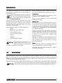
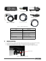
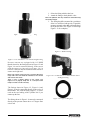
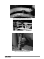
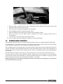
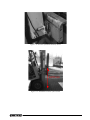
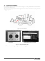
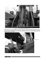
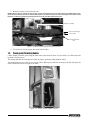
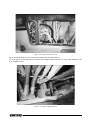
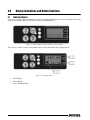
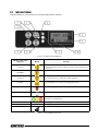
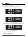
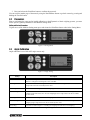
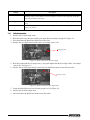
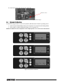
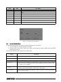
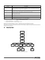
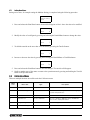
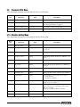
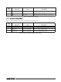
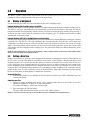
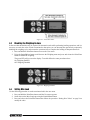
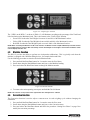
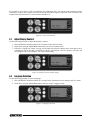
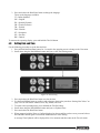
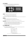
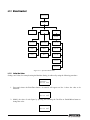
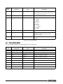
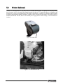
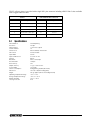
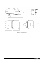
WLS-C
Wheel Loader Scale
Installation & User Manual
To be the best by every measure
115203
Contents
Introduction.............................................................................................................................................. 1
1.0
Installation ................................................................................................................................... 1
1.1
1.2
1.3
1.4
1.5
2.0
Indicator Installation . . . . . . . . . . . . . . . . . . . . . . . . . . . . . . . . . . . . . . . . . . . . . . . . . . . . . . . . . . . . . . 2
Pressure Sensor Installation . . . . . . . . . . . . . . . . . . . . . . . . . . . . . . . . . . . . . . . . . . . . . . . . . . . . . . . . 3
Proximity Sensors Installation . . . . . . . . . . . . . . . . . . . . . . . . . . . . . . . . . . . . . . . . . . . . . . . . . . . . . . . 6
Angle Sensor Installation . . . . . . . . . . . . . . . . . . . . . . . . . . . . . . . . . . . . . . . . . . . . . . . . . . . . . . . . . . 8
Passing and Protecting Cables. . . . . . . . . . . . . . . . . . . . . . . . . . . . . . . . . . . . . . . . . . . . . . . . . . . . . 10
Display Indications and Button Functions ................................................................................. 12
2.1 Indicator Display . . . . . . . . . . . . . . . . . . . . . . . . . . . . . . . . . . . . . . . . . . . . . . . . . . . . . . . . . . . . . . . . 12
2.2 Indicator Buttons . . . . . . . . . . . . . . . . . . . . . . . . . . . . . . . . . . . . . . . . . . . . . . . . . . . . . . . . . . . . . . . 13
3.0
Calibration ................................................................................................................................. 14
3.1 Entering Calibration Mode . . . . . . . . . . . . . . . . . . . . . . . . . . . . . . . . . . . . . . . . . . . . . . . . . . . . . . . . 14
3.2 Parameters. . . . . . . . . . . . . . . . . . . . . . . . . . . . . . . . . . . . . . . . . . . . . . . . . . . . . . . . . . . . . . . . . . . . 15
3.3 Angle Calibration . . . . . . . . . . . . . . . . . . . . . . . . . . . . . . . . . . . . . . . . . . . . . . . . . . . . . . . . . . . . . . . 15
3.3.1
Calibration procedure . . . . . . . . . . . . . . . . . . . . . . . . . . . . . . . . . . . . . . . . . . . . . . . . . . . . . . . . . . . . . 16
3.4 Dynamic Calibration . . . . . . . . . . . . . . . . . . . . . . . . . . . . . . . . . . . . . . . . . . . . . . . . . . . . . . . . . . . . . 17
3.5 Empty Calibration . . . . . . . . . . . . . . . . . . . . . . . . . . . . . . . . . . . . . . . . . . . . . . . . . . . . . . . . . . . . . . . 18
3.5.1
3.5.2
Performing an Empty Calibration . . . . . . . . . . . . . . . . . . . . . . . . . . . . . . . . . . . . . . . . . . . . . . . . . . . . . 18
Empty Calibration Options. . . . . . . . . . . . . . . . . . . . . . . . . . . . . . . . . . . . . . . . . . . . . . . . . . . . . . . . . . 18
3.6 Loaded Calibration . . . . . . . . . . . . . . . . . . . . . . . . . . . . . . . . . . . . . . . . . . . . . . . . . . . . . . . . . . . . . . 19
3.7 Menu Flow Chart . . . . . . . . . . . . . . . . . . . . . . . . . . . . . . . . . . . . . . . . . . . . . . . . . . . . . . . . . . . . . . . 20
3.7.1
Setting New Values . . . . . . . . . . . . . . . . . . . . . . . . . . . . . . . . . . . . . . . . . . . . . . . . . . . . . . . . . . . . . . . 21
3.8 Calibration Menu . . . . . . . . . . . . . . . . . . . . . . . . . . . . . . . . . . . . . . . . . . . . . . . . . . . . . . . . . . . . . . .
3.9 Password (PIN) Menu . . . . . . . . . . . . . . . . . . . . . . . . . . . . . . . . . . . . . . . . . . . . . . . . . . . . . . . . . . . .
3.10 Machine Setting Menu . . . . . . . . . . . . . . . . . . . . . . . . . . . . . . . . . . . . . . . . . . . . . . . . . . . . . . . . . .
3.11 Dynamic Setting Menu . . . . . . . . . . . . . . . . . . . . . . . . . . . . . . . . . . . . . . . . . . . . . . . . . . . . . . . . . .
4.0
21
22
22
23
Operation.................................................................................................................................... 24
4.1 Making a Weighment . . . . . . . . . . . . . . . . . . . . . . . . . . . . . . . . . . . . . . . . . . . . . . . . . . . . . . . . . . . .
4.2 Setting a New Tare. . . . . . . . . . . . . . . . . . . . . . . . . . . . . . . . . . . . . . . . . . . . . . . . . . . . . . . . . . . . . .
4.3 Disabling the Weighing Feature . . . . . . . . . . . . . . . . . . . . . . . . . . . . . . . . . . . . . . . . . . . . . . . . . . . .
4.4 Setting Max Load . . . . . . . . . . . . . . . . . . . . . . . . . . . . . . . . . . . . . . . . . . . . . . . . . . . . . . . . . . . . . . .
4.5 Machine Function . . . . . . . . . . . . . . . . . . . . . . . . . . . . . . . . . . . . . . . . . . . . . . . . . . . . . . . . . . . . . . .
4.6 Correction Function . . . . . . . . . . . . . . . . . . . . . . . . . . . . . . . . . . . . . . . . . . . . . . . . . . . . . . . . . . . . .
4.7 Adjust Display Contrast . . . . . . . . . . . . . . . . . . . . . . . . . . . . . . . . . . . . . . . . . . . . . . . . . . . . . . . . . .
4.8 Language Selection . . . . . . . . . . . . . . . . . . . . . . . . . . . . . . . . . . . . . . . . . . . . . . . . . . . . . . . . . . . . .
4.9 Setting Date and Time . . . . . . . . . . . . . . . . . . . . . . . . . . . . . . . . . . . . . . . . . . . . . . . . . . . . . . . . . . .
4.10 Diagnostics . . . . . . . . . . . . . . . . . . . . . . . . . . . . . . . . . . . . . . . . . . . . . . . . . . . . . . . . . . . . . . . . . . .
4.11 Printing the Ticket . . . . . . . . . . . . . . . . . . . . . . . . . . . . . . . . . . . . . . . . . . . . . . . . . . . . . . . . . . . . . .
4.12 Menu Flowchart . . . . . . . . . . . . . . . . . . . . . . . . . . . . . . . . . . . . . . . . . . . . . . . . . . . . . . . . . . . . . . .
4.12.1
24
24
25
25
26
26
27
27
28
29
29
30
Setting New Values . . . . . . . . . . . . . . . . . . . . . . . . . . . . . . . . . . . . . . . . . . . . . . . . . . . . . . . . . . . . . . . 30
4.13 User Menu . . . . . . . . . . . . . . . . . . . . . . . . . . . . . . . . . . . . . . . . . . . . . . . . . . . . . . . . . . . . . . . . . . . 31
Technical training seminars are available through Rice Lake Weighing Systems.
Course descriptions and dates can be viewed at www.ricelake.com/training
or obtained by calling 715-234-9171 and asking for the training department.
© 2010 Rice Lake Weighing Systems. All rights reserved. Printed in the United States of America.
Specifications subject to change without notice.
Rice Lake Weighing Systems is an ISO 9001 registered company.
Version 1.0, December 2010
i
4.14 Time Setting Menu . . . . . . . . . . . . . . . . . . . . . . . . . . . . . . . . . . . . . . . . . . . . . . . . . . . . . . . . . . . . . 32
4.15 Sensors Check Menu. . . . . . . . . . . . . . . . . . . . . . . . . . . . . . . . . . . . . . . . . . . . . . . . . . . . . . . . . . . 33
4.15.1
4.15.2
4.15.3
5.0
Input Status Menu . . . . . . . . . . . . . . . . . . . . . . . . . . . . . . . . . . . . . . . . . . . . . . . . . . . . . . . . . . . . . . . 33
On/Off Outputs Menu . . . . . . . . . . . . . . . . . . . . . . . . . . . . . . . . . . . . . . . . . . . . . . . . . . . . . . . . . . . . . 33
Pressure Sensor Menu . . . . . . . . . . . . . . . . . . . . . . . . . . . . . . . . . . . . . . . . . . . . . . . . . . . . . . . . . . . . 33
Printer (Optional) ....................................................................................................................... 34
5.1 Specifications . . . . . . . . . . . . . . . . . . . . . . . . . . . . . . . . . . . . . . . . . . . . . . . . . . . . . . . . . . . . . . . . . 35
WLS-C Limited Warranty........................................................................................................................ 37
For More Information ............................................................................................................................. 38
Rice Lake continually offers web-based video training on a growing selection
of product-related topics at no cost. Visit www.ricelake.com/webinars.
ii
WLS-C Wheel Loader Scale
Introduction
This manual is intended for use by technicians
responsible for installing and servicing the WLS-C
Wheel Loader Scale.
Authorized distributors and their employees
can view or download this manual from the
Rice Lake Weighing Systems distributor site
at www.ricelake.com.
Unpack the contents of the shipment your system
arrived in and verify the contents are correct, using the
packing slip. Check for damage that could have
occurred during shipment, and report any
discrepancies immediately.
Before installing, ensure you have the following:
• Welder
• Mechanical and electrical tools
• Set of assorted wrenches
• Set of assorted screwdrivers
• Grinder
• Voltmeter
• Assorted hydraulic fittings
If washing the machine with a
high-pressure power washer, you
must protect all system components
from direct spraying to avoid damage.
Warning
1.0
Before installing the WLS-C Wheel Loader Scale,
take the following measures to ensure your safety:
Protective Gear
Always wear safety goggles, as required by safety
conditions, when welding or grinding.
Never wear loose clothing or jewelry, which may get
caught in the machine.
Hydraulic Parts
Discharge all pressure from the hydraulic circuit
before disconnecting or removing any plumbing,
connector, or relative component. Always make
certain that all moving parts have been locked and
check for any residual pressure when disconnecting
any hydraulic plumbing.
Always let the bucket or other similar parts down to
ground-level before carrying out any work on the
machine. If this cannot be done, make sure that bucket
is locked so it cannot come suddenly and
unexpectedly down.
Damaged or detached fuel and lubricant lines can
cause fire. Never bend or strike high pressure lines,
nor put damaged or twisted ones back on. Always
check pipes and ducts.
Repairs
Detach the battery and let any remaining charge out
before carrying out any work on the vehicle.
If possible, have the vehicle brought into a shed or
onto a hard, clean floor.
Installation
When installing the components, use the appropriate brackets supplied. These can be mounted inside the cab
onto the cab structure. It is recommended that you consult the machine’s operator to ensure the indicator is
mounted in a convenient location based on their needs. Make sure the components do not restrict the operator’s
vision or interfere with bodily movements.
On forklift trucks, the unit is mounted directly under the roof. You will need to make threaded holes in the frame.
Do not attach the brackets to the dashboard or other non-metallic surface. Prior to altering the
Warning cab structure, customer approval should be attained due to EROPS and ROPS certifications.
WLS-C Wheel Loader Scale - Installation
1
Indicator
Pressure transducer
Angle sensor
Proximity
Sensor and Cable
Pressure transducer cable
Indicator with wiring (see
Table 1-1 for cable details)
Figure 1-1. WLS-C Component List
Wire
Connect To
PT1
Pressure transducer
PT2
Second pressure transducer (optional)
Prox1
Angle sensor on chassis
Prox2
Angle sensor on boom
Power (Brown/White)
Positive terminal on battery
Power (Green/Yellow)
Negative terminal on battery
Table 1-1. Cable Harness
1.1
Indicator Installation
1. Use the bracket as a template to drill holes. Then, mount the bracket. Or, use the suction cup mount.
2. Fasten screws holding the bracket in place. The bracket can now accept the indicator.
3. Loosen the bracket handle shown in Figure 1-2, find the desired angle, and tighten the handle.
Bracket handle
Figure 1-2. Bracket screwed in place
2
WLS-C Wheel Loader Scale
Figure 1-3. Indicator Mounted in Cab
Figure 1-4. Indicator Back
1.2
Pressure Sensor Installation
The pressure sensor reads the main line pressure of the lift cylinder (hydraulic line). Only one sensor is required;
however, the WLS-C Wheel Loader Scale may be used with two pressure sensors if needed. There are two
options for pressure sensor installation:
• Install a flange block where the hydraulic line attaches to the hydraulic fluid distributor. Use one of the
fittings supplied to attach the sensor to the flange block. The kit comes with a few common fittings
which fit the majority of wheel loaders. It may be required to locate special fittings for the installation.
See Figure 1-5 through Figure 1-8 for a list of provided fittings.
NOTE: Some manufacturers do not use flange blocks. In these cases, use a swivel T-fitting.
•
Attach the weld-on flange (supplied, see Figure 1-7 4) directly to the hydraulic line. This should be
performed by a qualified welder to ensure proper fitting and seal.
Note: The best source for flange blocks is the local heel loader or skid steer dealer that sold the machine originally. An
alternative source for flange blocks is www.mainmfg.com/mainhome.html.
WLS-C Wheel Loader Scale - Installation
3
1. Select the fitting which works best.
2. Attach the fitting to the hydraulic valve.
Note: The hydraulic line may need to be removed if using
the weld-on flange.
3. The fitting should be mounted in a position to
allow it to self-bleed with gravity. If possible,
mount at an angle rather than perpendicular to
the hydraulic line. (See Figure 1-10 through
Figure 1-13 for examples).
Figure 1-5. 1/4" BSPP Straight Fitting
Figure 1-7. Weld-on Flange
Figure 1-6. 1/4" NPT Male to 1/4" Female Straight Fitting
Pressure sensors are equipped with 1/4" BSPP
threads; therefore, the fittings shown in Figure 1-5 and
Figure 1-6 can be connected directly to the sensor
with the copper o-ring seal (see Figure 1-9) in
between. This seal must be installed on all sensors to
ensure an air-tight seal.
Notes: The copper o-ring seal has a smooth side and a
rough side. The seal should be installed so the smooth
side touches the sensor.
Figure 1-8. 1/4" NPT male to 1/4" BSPP Female Swivel
90-Degree Fitting
There is also a rubber gasket on the sensor (see
Figure 1-13 on page 6). Keep this in a safe place until
ready to install, as it falls off easily.
The fittings shown in Figure 1-5, Figure 1-6 and
Figure 1-8 can be connected directly to the valve of
the machine. The weld-on fitting (Figure 1-7) can be
used on the steel tubing of the cylinder line if you
cannot tap the line.
The fitting shown in Figure 1-8 cannot be connected
directly to the pressure sensor due to a 37-degree flare
swivel end.
4
WLS-C Wheel Loader Scale
Figure 1-9. Copper O-Ring Seal
Figure 1-10. Flange Welded to Hydraulic Line at Desired Angle
Figure 1-11. Sensor Mounted at Non-Recommended Angle
Figure 1-12. Sensor Mounted at Recommended Angle
WLS-C Wheel Loader Scale - Installation
5
Rubber gasket
Figure 1-13. Sensor Mounted at Recommended Angle; Rubber Gasket Highlighted
4. Place the copper o-ring between the sensor and fitting (with the smooth side towards the sensor) and
tighten the sensor with a crescent wrench.
5. Once the sensor is mounted, the hydraulic line can be bled.
6. After starting the machine, partially loosen the sensor.
7. Wait until fluid leaks out without any air bubbles before tightening it down.
8. Route wire back to the cab. Route along a stationary area; tying to existing electrical lines is
recommended.
9. Tie off excess wire in an open area of the wheel loader.
10. Check for leaks again after running the machine for a short period of time.
1.3
Proximity Sensors Installation
Positioning the proximity sensors is extremely important for the accuracy of weighing during the lifting stage.
You must make sure you install them in such a way that the lifting reference notch activates the first proximity
switch, and that it remains active even when the second has been activated.
If the weighing system is running properly, the acoustic indicator will go off after the second proximity has been
reached. This means a measurement has been made. On the other hand, when the vehicle arm is coming down, it
must first activate the second proximity, and then the first. This is so weighing takes place only during lifting and
not lowering.
In forklift trucks, the distance between the two must be about 20 cm, given the speed at which the forks rise.
This layout has been tested on many different models, and has been seen to be the best, because hydraulic
pressure tends to remain more stable and give a greater proportional increase. For forklifts, we suggest you place
the first switch 40–50 cm above the lowest point. See Figure 1-15 on page 7
NOTE: The proximity switch cannot read if positioned more than 5 mm away from the reading plate. You should always
try to place them about 2–3 mm apart.
6
WLS-C Wheel Loader Scale
Figure 1-14. Location of Installed Proximity Sensor
40/50 cm
Figure 1-15. Installation Location of First Switch
WLS-C Wheel Loader Scale - Installation
7
1.4
Angle Sensor Installation
Place the chassis and boom angle sensors as shown in Figure 1-16. They should both be horizontal with the
connector in the cabin direction.
Two sensors are necessary because the relative angle between the chassis and the boom is used to perform the
weighing computation.
Figure 1-16. Sensor Placement
1. Using two to three 1" beads, weld the angle sensor’s mounting plate to the inside of the support arm.
Mounting plate
Mounting plate with angle sensor attached.
Figure 1-17. Angle Sensor Mounting Plate
2. Fasten the sensor housing and angle sensor to the mounting plate.
8
WLS-C Wheel Loader Scale
Angle Sensor
Figure 1-18. Angle Sensor Installed On Support Arm
NOTE: Angle sensors should be installed in line with the opening and bolt for the arm and must parallel on the boom.
There are 3 bolts on the angle sensor: 1 on top and 2 on the bottom. The angle sensor should be installed so that the 1
bolt side faces up and the side with 2 bolts faces down. If installed correctly, the wire will be toward the cab of the
loader. See Figure 1-19 on page 9.
Angle Sensors
Figure 1-19. Angle Sensors Installed
WLS-C Wheel Loader Scale - Installation
9
3. Route the sensor’s wire back to the cab.
NOTES: Ensure there is enough slack in the wire to allow the support arm to raise fully without over-tightening the wire.
Route along a stationary area of the wheel loader. Figure 1-20 shows the pressure sensor and angle sensor wires routed
between a stationary cylinder and existing electrical line; this provides optimal protection.
stationary cylinder
pressure and angle
sensor wires
existing electrical
line
Figure 1-20. Wires Routed Along Existing Electrical Line.
4. Tie off excess wire in an open area of the wheel loader.
1.5
Passing and Protecting Cables
Cables should, if possible, pass along the same route as the electrics cables of your vehicle, or at least where the
hydraulic circuitry passes.
This means that there are basically two cables to protect: proximity and transducer cables.
You should always leave some leeway for the cables. When giving full-lock steering to the left and right, the
cables should not become too tight or too slack.
Figure 1-21. Proper Amount of Slack in Cables
10
WLS-C Wheel Loader Scale
Figure 1-22. Cables Routed Correctly
Do not mount the cables too close to the motor, unless they are well insulated.
If you use clips to fix the cables down, remember not to tighten them too much. Very often, cable breakage is due
to over-tightened clips.
Figure 1-23. Cables Clipped Properly
WLS-C Wheel Loader Scale - Installation
11
2.0
2.1
Display Indications and Button Functions
Indicator Display
Once power is applied, the system performs a self-test and displays the software version and the date of the latest
upgrade. For example, WS06_05 (WS06_XX) 28/2/2010 (DD/MM/YY).
Figure 2-1. WLS-C Software Version and Date of Last Update
This screen is visible for only a few moments before it clears and displays the weighing screen.
Figure 2-2. Weighing Screen
1. Total Weight
2. Partial Weight
3. Active Weighing Mode
12
WLS-C Wheel Loader Scale
2.2
Indicator Buttons
Indicator buttons are your interface for communicating with the indicator.
Figure 2-3. Indicator Keypad Buttons
Number referenced in
Figure 2-3
Button
1
Total/Plus
Function
Press and hold for 3 seconds to zero.
In static weighing mode without input, this button adds the partial load
to the total.
2
Partial/Minus
Partial zeroing button.
3
Print/Enter
Press and hold for 3 seconds to access Operation menu.
Press and release once to print ticket (optional printer)
4
Tare/Sel
Press and release once to memorize new Tare.
Press and hold for 3 seconds for zeroing the Tare value.
5
When lit indicates Tare value is other than zero.
6
When lit indicates Tare value equals zero.
7
Indicator lights warning for maximum load. See “Setting Max Load” on
page 25.for more information.
8
987.65
Total Weight
9
12.34
Partial Weight
10
Symbol of active weighing mode.
Table 2-1. Keypad Button Functions
WLS-C Wheel Loader Scale - Display Indications and Button Functions
13
3.0
Calibration
To calibrate the WLS-C, you must enter calibration mode. This allows you to alter system settings.
3.1
Entering Calibration Mode
Use the following procedure to access the calibration menu from the operating screen.
1. Press and hold the Print/Enter button until the User Menu appears.
2. Scroll down the menu list using the Partial/Minus button to reach the Setting Menu.
Figure 3-1. Setting Menu
3. Press and release the Print/Enter button to enter the menu.
The display indicates CAL: PIN 0.
Figure 3-2. Enter Calibration PIN
4. Enter the password 4482 to access the calibration area. See “Setting New Values” on page 21. to
complete changes.
Figure 3-3. Calibration PIN Entered
Once the values are entered, follow the procedure below to confirm it.
1. Press and release the Print/Enter button to confirm the changes made.
The asterisk will disappear.
2. Press and release the Partial/Minus button.
14
WLS-C Wheel Loader Scale
3. Press and release the Print/Enter button to confirm the password.
You can scroll to another page of the menu by using the Partial/Minus button or go back a menu by pressing and
holding the Tare/Sel button.
3.2
Parameters
Prior to performing the empty and/or loaded calibration on both Dynamic or Static weighing systems, you must
set the system’s general parameters in the Machine Setting menu.
Setting and Saving Parameters
To gain access to the Machine Setting menu press and release the Print/Enter button when in the Setting Menu.
Figure 3-4. Setting Menu
3.3
Angle Calibration
Angle calibration is used with ASC angle sensors only.
Figure 3-5. Angle Setting
Setting
Description
Side
The position of angle sensor on the boom, (LEFT-RIGHT), press and release the Print/Enter
button to change the mounting side. Left is standard.
Act Angle
The actual value of relative angle, or the difference between the angles of boom and chassis.
Angle value if left side should be positive value
Start Ang
The value of relative angle for the start weighing point selected.
Get Start Angle
Press and release the Print/Enter button to memorize the actual value of relative angle as the start
weighing angle with the boom in the start weighing position. Angle value if left side should be
positive value.
End Ang
The value of relative angle for the end weighing.
Get End Angle
Press and release the Print/Enter button to memorize the actual value of relative angle as end
weighing angle. Angle value if left side should be positive value
Reset Ang
The value of relative angle for concluding the weighing and start with a new weighing.
Table 3-1. Angle Settings
WLS-C Wheel Loader Scale - Calibration
15
Setting
Description
Get Reset Angle
Press and release the Print/Enter button to memorize the actual value of relative angle to reset the
weighing angle cycle. Should be set around 10 degrees lower than start weigh value. Angle value
if left side should be positive value.
Delete Angles
Press and release the Print/Enter button to erase all angles value (Start Ang., End Ang., Reset
Ang.).
Save
To save the angle calibration values to the memory. Must be done after completing to save the
data to the memory.
Table 3-1. Angle Settings
3.3.1
1.
2.
3.
4.
Calibration procedure
Scroll to the Get Start Angle menu.
Raise the bucket up to the start weighing area point. Bucket should be straight. See Figure 3-6.
Press and release the Print/Enter button to store the value.
Scroll to the Act Angle and record the value. An example value is 146.
Bucket Position
Figure 3-6. Bucket Position for Get Start Angle
5. Raise the bucket until the Act Angle value is 100 points higher than the Start Angle Value. An example
value is 245. See Figure 3-7.
6. Scroll to the Get End Angle and press and release the Print/Enter button to store that end value.
Bucket Position
Figure 3-7. Bucket Position for Start Angle Value
7. Lower the bucket about one foot from the ground level. See Figure 3-8.
8. Scroll to the Get Reset Angle menu.
9. Press and release the Print/Enter button to store that value.
16
WLS-C Wheel Loader Scale
10. Scroll down to the Save and save the Angle Cal
Bucket Position
Figure 3-8. Bucket Position for Get Reset Angle
3.4
Dynamic Calibration
Use the following procedure to access the dynamic calibration menu from the operating screen.
1. Scroll using the Partial/Minus button to the Dynamic Cal. menu from the Setting Menu.
2. Select empty or loaded calibration (Empty Cal. or Loaded Cal.).
NOTE: If the WLS-C has been configured for static weighing mode, access to this menu will be denied.
Figure 3-9. Dynamic Calibration
WLS-C Wheel Loader Scale - Calibration
17
3.5
Empty Calibration
3.5.1
Performing an Empty Calibration
User the following procedure to perform an empty calibration.
1. Scroll to Empty Cal. from the Dynamic Cal. menu.
2. Perform 10 empty lifts at decreasing RPM settings, starting at the max RPM with the bucket closed.
3.5.2
Empty Calibration Options
The menu includes the following data:
Setting
Description
Time
Time elapsed during the lift, the lower this value is, the greater the speed of the lift cycle.
TP1 value
Indicates the piston’s pressure transducer reading.
TP2 value
Indicates the rod’s pressure transducer reading (if installed).
EmptyLoad1
Set the real load for calibration 1 usually is set to“0”, because the calibration is performed with the
machine empty
ET11 point
Displays the number of lifts performed at decreasing speed, which will correspond to the number
of points recorded in empty calibration1 table, (refer ET1 xxxx: -xxxxx)
ET1 xxxx: -xxxxx
Allows viewing the complete empty calibration 1 table, it is possible to view two values: the left
value corresponds the index table, whereas the value on the right corresponds the acquired value
of the table. See Table 3-3.
EmptyLoad2
Set the real load for calibration 2 usually is set to“0”, because the calibration is performed with the
machine empty: if different, insert the value according to the machine’s capacity, keeping in mind
the decimals to be displayed, and the resolution preferred (this value can also be set at the end of
the calibration).
ET22 point
Displays the number of lifts performed at decreasing speed, which will correspond to the number
of points recorded in empty calibration 2 table, (refer ET2 xxxx: -xxxxx)
ET2 xxxx: -xxxxx
Allows viewing the complete empty calibration 2 table. It is possible to scroll through the table by
selecting the index number.
Delete Cal. 1
Used to delete calibration 1 data.
Delete Cal. 2
Used to delete calibration 2 data.
Save
To save all modifications to the empty calibration.
Table 3-2. Empty Calibration Settings
1. Table empty calibration 1 - First machine
2. Table empty calibration 2 - Second machine, if exists
NOTE: Once the empty calibration of 10 lifts is completed you must save the data to the memory.
Index Range 0-59, Points Table Range 0-19
Index
Table
Description
0
1
Time
1
1
Back side cylinder pressure or differential pressure
2
2
Time
Table 3-3. Index and Table Range
18
WLS-C Wheel Loader Scale
Index
Table
Description
3
2
Back side cylinder pressure or differential pressure
4
3
Time
5
3
Back side cylinder pressure or differential pressure
6
4
Time
7
4
Back side cylinder pressure or differential pressure
X
N
Time
Y
N
Back side cylinder pressure or differential pressure
Table 3-3. Index and Table Range
Figure 3-10. Empty Calibration Display
3.6
Loaded Calibration
Use the following procedure to perform a loaded calibration proceed as follows.
1. Access Loaded Cal. from the Dynamic Cal. menu.
2. Perform 10 lifts with a known load in the bucket at decreasing rpm settings, starting at the max RPM
with the bucket closed.
The Loaded Calibration menu includes the following data:
Setting
Description
Time
Time elapsed during the lift, obviously the lower this value, the greater the speed of the lift.
TP1 value
Indicates the piston’s pressure transducer reading.
TP2 value
Indicates the rod’s pressure transducer reading (if installed).
KnownLoad1
Set the known load for calibration 1: insert the value according to the machine’s capacity, keeping
in mind the decimals to be displayed, and the resolution preferred (this value can also be set at
the completion of the calibration).
LT11 point
Displays the number of lifts performed at decreasing speed, which will correspond to the number
of points recorded in loaded calibration 1 table, (refer LT1 xxxx: -xxxxx)
LT1 xxxx: -xxxxx
Allows viewing the complete loaded calibration 1 table. It is possible to scroll through the table by
selecting the index number.
Table 3-4. Loaded Calibration Settings
WLS-C Wheel Loader Scale - Calibration
19
Setting
Description
KnownLoad2
Set the known load for calibration 2(if available): insert the value according to the machine’s
capacity, keeping in mind the decimals to be displayed, and the resolution preferred (this value
can also be set at the completion of the calibration).
LT22 point
Displays the number of lifts performed at decreasing speed, which will correspond to the number
of points recorded in loaded calibration 2 table, (refer LT2 xxxx: -xxxxx).
LT2 xxxx: -xxxxx
Allows viewing the complete loaded calibration 2 table. It is possible to scroll through the table by
selecting the index number.
Delete Cal. 1
Used to delete calibration 1 data.
Delete Cal. 2
Used to delete calibration 2 data.
Save
Save permanently all modifications to the loaded calibration.
Table 3-4. Loaded Calibration Settings
1. Table loaded calibration 1 - First machine
2. Table loaded calibration 2 - Second machine, if exists
NOTE: Once the loaded calibration of 10 lifts is completed you must save the data to the memory.
Knownload is set based on what the measurement is used. Example: weight is 4230 lbs enter 4230 in knownload.
If load is 2.31 ton enter 231.
3.7
Menu Flow Chart
Operating Screen
Operation Menu
Calibration
PIN
Machine
Setting
Static
Setting
Dynamic
Setting
Empty Cal
Angle
Setting
Weighing
Mode
Loaded Cal
Figure 3-11. Calibration Menu Flow
20
WLS-C Wheel Loader Scale
Advanced
Setting
Protected by
Advanced
PIN
3.7.1
Setting New Values
Setting a new value, for example setting the Machine Setting, is completed using the following procedure.
Machine Setting
Rod 1
1. Press and release the Print/Enter button. An asterisk will appear on line 1 above the value to be modified.
*
0
Rod 1
2. Modify the value of each figure by pressing and releasing the Partial/Minus button to change the value.
*
1
Rod 1
3. To shift the asterisk on the next value to be modified by pressing the Tare/Sel button.
*
Rod 1
1
4. Increase or decrease the value by pressing and releasing the Partial/Minus or Total/Plus button.
*
Rod 1
61
5. Press and release the Print/Enter button to save the changes. The asterisk will disappear.
6. Scroll to another page of the menu or return to the operation menu by pressing and holding the Tare/Sel
button to the previous menu.
3.8
Calibration Menu
There are multiple functions accessible under the Calibration menu.
Menu
Line
Menu Text
Type
Description
1
Setting Menu
Text
2
Machine Setting
Access sub-menu
Access Machine Setting menu. Use to set weighing
system main parameters.
2
Static Cal
Access sub-menu
Access to static calibration menu.
2
Dynamic Cal
Access sub-menu
Access to dynamic calibration menu, subdivided in
two sections; empty and loaded.
2
Angle Setting
Access sub-menu
Access to angles calibration menu.
2
Advanced Setting
Access sub-menu
Reserved for manufacturer’s settings.
Table 3-5. Calibration Settings Menu
WLS-C Wheel Loader Scale - Calibration
21
3.9
Password (PIN) Menu
There are multiple functions accessible under the Password (PIN) menu.
Menu
Line
Menu Text
Type
Description
1
2
CAL. PIN XXXX
Setting
Insert the PIN to gain access to the calibration menu.
See “Setting New Values” on page 21.
2
Enter to Confirm
Command
Press Enter to confirm the PIN setting.
2
Access Denied
Viewing
This message is displayed if the PIN is incorrect.
Table 3-6. Password Settings Menu
3.10 Machine Setting Menu
There are multiple functions accessible under the Machine Setting menu.
Menu
Line
Menu Text
Type
Description
1
Machine Setting
Text
2
Cylinder 1 xxxx
Setting
Setting lifting cylinder’s circumference for calibration
1, set in cm.
2
Rod 1 xxx
Setting
Setting cylinder rod’s circumference for calibration 1,
set in cm.
2
Thickness1 xxxx
Setting
Setting lifting cylinder’s thickness for calibration 1, set
in cm.
2
Cylinder 2 xxxx
Setting
Setting lifting cylinder’s circumference for calibration
2, set in cm.
2
Rod 2 xxxx
Setting
Setting cylinder rod’s circumference for calibration 2,
set in cm.
2
Thickness2 xxxx
Setting
Setting lifting cylinder’s thickness for calibration 2, set
in cm.
2
Round Val. xxxx
Setting
Setting rounding off value of partial weight. Default = 0
2
Active Angle x
Setting
Setting number for active angle sensor, range 0-1.
0 = Proximity Switch
1 = Angle Sensor (Default)
2
n.Decimals
Setting
Setting number of decimals for both partial and total
weight, range 0-3. Default = 2
2
Unit Print
Command
Selecting units of measure (0-none, 1-Kg, 2-Tons,
3-Lb., 4-Short Tons, 5-Cubic Meters) which will be
printed on the ticket.
NOTE: Only available if a printer is installed.
2
Del Ticket Num.
Command
Zeroing the progressive number on the ticket.
2
Use Reg. x
Setting
Enable or disable the regenerative valve management.
Table 3-7. Machine Settings Menu
22
WLS-C Wheel Loader Scale
Menu
Line
Menu Text
Type
Description
2
Th. Reg. xxxx
Setting
Setting threshold in reading Adc point to know if the
regenerative valve is On or Off.
2
Save
Command
Saving permanently all modifications to parameters.
Table 3-7. Machine Settings Menu
3.11 Dynamic Setting Menu
There are multiple functions accessible under the Dynamic Setting menu.
Menu
Line
Menu Text
Type
Description
1
Dynamic Setting
Text
2
Empty Cal.
Access to sub-menu
Access to empty calibration menu.
2
Loaded Cal.
Access to sub-menu
Access to loaded calibration menu.
Table 3-8. Dynamic Loaded Calibration Settings Menu
WLS-C Wheel Loader Scale - Calibration
23
4.0
Operation
The WLS-C system is based on the measurement of the lift cylinder piston pressure (by means of the pressure
transducer) and the calculation of the raise speed (with angle sensor).
4.1
Making a Weighment
Use the following procedure to weigh a load based on the Active Weighing mode.
Dynamic Weighing with 2 Proximity Sensors on Forklifts
Following the initial lift off the ground, maintain a constant lifting speed during the complete weighing cycle.
The WLS-C will begin calculating the load automatically when the first proximity is activated, and will be
completed when the second proximity is then activated. The buzzer will start beeping when the first proximity is
activated, and will continue until the completion of the weighing cycle. The partial load will then be added
automatically to the total weight.
Dynamic Weighing with 2 ASC or Proximity Sensors on Front Loaders
Fill the bucket, begin lifting maintaining fully open raise function and a constant RPM speed during the complete
weighing cycle. The WLS-C will begin calculating the load automatically when the ASC sensor angle start
weigh angle is or when the first proximity is activated, and will be completed when the ASC sensor end weigh
angle or second proximity is then activated. The buzzer will start beeping when the sensors are activated, and
will continue until the completion of the weighing cycle. The partial load will then be added automatically to the
total weight.
NOTE: Avoid weighing with the machine tilted sideways, and/or sloping forward or backward. Avoid sudden and/or
abrupt movements during the weighing operation.
4.2
Setting a New Tare
Setting a new tare may be necessary when changing the actual bucket, changing the viscosity of the hydraulic oil
in the circuit, or when some material accumulates in the bucket, which cannot be dislodged during normal
dumping operation. It’s a known fact that the quantity of material accumulated in a bucket, after the first few
cycles, stays more or less constant, therefore by setting a new tare, it enables zeroing the extra weight of the
bucket, weighing only the material effectively dumped in the body of the truck. It is advisable to verify the status
of the tare prior to beginning loading operations, by performing an empty weighing; in the eventuality that the
partial weight is not “0”carry out the tare zeroing as described below. Repeat this operation a few times during
the day to compensate for the hydraulic oil temperature variations.
Zeroing Existing Tare
1. With an empty bucket, press and hold the Tare/Sel button until the lower LED is illuminated, the Tare
value will be zeroed.
Acquiring a new Tare:
1. Perform an empty weighing based on the active weighing mode shown on the WLS-C screen. See
“Making a Weighment” on page 24. for more information.
The screen will display a value for the partial weight.
2. Press and release the Tare/Sel button.
The upper LED will illuminate and the new Tare value will be acquired.
NOTE: To view the actual Tare value go to the User Menu by press and holding the Print/Enter button.
24
WLS-C Wheel Loader Scale
Figure 4-1. Actual Tare Value
4.3
Disabling the Weighing Feature
In the case that the machine may be required for alternative tasks while performing loading operations, and it is
necessary to retain the value of load accumulated to that point, you can interrupt the operation by temporarily
disabling the weighing cycle, and resume the operations later to complete the loading of that particular truck.
1. Press and hold the Print/Enter button to access the User menu.
2. Using the Partial/Minus button scroll down to the Weighing menu and press and release the Print/Enter
button to disable the weighing.
The green LED will go out on the display. To enable follow the same procedure above.
On: Weighing Enabled
Off: Weighing Disabled
Figure 4-2. Weighing Enabled
4.4
Setting Max Load
Use the following procedure to set the maximum load in the user menu.
1. Press and hold the Print/Enter button until the User menu appears.
2. Scroll down to the Max Load page using the Partial/Minus button.
3. Press and release the Print/Enter button then follow the procedure “Setting New Values” on page 30 to
modify the value.
WLS-C Wheel Loader Scale - Operation
25
Figure 4-3. “Traffic Light” Function
The 3 LED’s on the WLS-C, as shown in Table 4-3, will illuminate according to the percentage of the Total Load
lifted in relation to the Maximum Load. This is also known as the “Traffic Light” function.
• Green LED: lit when the Total Weight is between 0% and 89% of the Maximum Load set.
• Yellow LED: lit when the Total Weight is between 90% and 99% of the Maximum Load set.
• Red LED: lit when the Total Weight equals or exceeds 100% of the Maximum Load set.
NOTE: When exceeding the Maximum Load set for first time, the WLS-C will emit 3 rapid audible beeps and will continue
each weighing that exceeds the Max load setting, until the Total Weight is zeroed (press and hold the Total/Plus button
until the display indicates zero
4.5
Machine Function
The WLS-C provides the ability to perform two independent calibrations,. This is typically used when the
machine is equipped with 2 different lifting devices, for example bucket and forks.
Use the following procedure to select the desired calibration mode.
1. Press and hold the Print/Enter button for 3 seconds to enter the User Menu.
2. Scroll down using the Partial/Minus button until you see the Machine heading.
3. Press and release the Print/Enter button to change the Machine number.
Figure 4-4. Machine Number
4. To return to the main operating screen press and hold the Tare/Sel button.
NOTE: This selection is not possible if the regenerative valve management is enabled.
4.6
Correction Function
The Correction function is used to adjust a constant error in each weighing cycle without changing the
calibration.
1. Press and hold the Print/Enter button for 3 seconds to enter the User menu.
2. Scroll down using the Partial/Minus button until you see the Correction menu.
3. Press and release the Print/Enter button and follow the procedure “Setting New Values” on page 30 to
modify the correction percentage.
26
WLS-C Wheel Loader Scale
It is possible to set a factor of ±10% in relation to the calibration value. 110 indicates the maximum positive
correction to increase the weighed load, 90 indicates the maximum negative correction factor to decrease the
weighed load, and 100 means no correction factor should be set
Figure 4-5. Correction Function
4.7
Adjust Display Contrast
Use the following procedure to adjust the display’s contrast.
1. Press and hold the Print/Enter button for 3 seconds to enter the User menu.
2. Scroll down using the Partial/Minus button until you see the Contrast menu.
3. Follow the “Setting New Values” on page 30 procedure to modify the contrast value, which can be set to
a minimum value of 60, and a maximum of 160 (by lowering the value the display will fade, and
increasing the value it will darken). 110 is the normal setting.
Figure 4-6. Display Contrast Normal Setting
4.8
Language Selection
Use the following procedure to select a language.
1. Press and hold the Print/Enter button for 3 seconds in the operating screen to change to the User menu.
2. Scroll down using the Partial/Minus button until you see the Language menu.
Figure 4-7. Language Selection
WLS-C Wheel Loader Scale - Operation
27
3. Press and release the Print/Enter button to change the language.
These are the languages available:
IT = Italian (Italiano)
UK = English
ES = Spanish (Espanol)
FR = French (Francais)
TR = Turkish
FM = Flemish
PT = Portuguese
GE = German
DK = Danish
To return to the operating display, press and hold the Tare/Sel button.
4.9
Setting Date and Time
Use the following procedure to set the date and time.
1. Press and hold the Print/Enter button for 3 seconds in the operating screen to change to the User menu.
2. Scroll down using the Partial/Minus button until you see the Time Setting menu.
Figure 4-8. Time Setting
3. Press and release the Print/Enter button to select the time.
4. Use the Partial/Minus button to scroll to each sub-menu, then use the procedure “Setting New Values” on
page 30 to set each feature: Minute, Hour, Day, Month, and Year.
5. To return to the Operating menu, press and hold the Tare/Sel button.
6. Scroll down using the Partial/Minus button until you see Updated Time.
7. Press and release the Print/Enter button
8. When prompted with the Enter to Confirm displayed on the second line on the screen, press and release
the Print/Enter button again to confirm the modifications to Time Setting.
A message Time Updated! will be displayed for a few moments and then return to the Tare sub-menu.
28
WLS-C Wheel Loader Scale
4.10 Diagnostics
The “Sensors Check menu” allows viewing the status of all inputs and outputs.
1. Press and hold the Print/Enter button for 3 seconds to enter the User menu.
2. Scroll to the User menu from the operating screen.
3. Scroll down using the Partial/Minus button until you see the Sensors Check page.
Figure 4-9. Sensor Check Menu
4. Press and release the Print/Enter button to enter the sub-menu.
Proximity
To select the second Proxy press and release the Print/Enter button.
• Proxy 1 (to visualize the status of the 1stproximity switch)
• Proxy 2 (to visualize the status of the 2ndproximity switch)
The Proximity status is normally Off, however during the weighing cycle, they become active, the status is On
momentary.
On-Off Outputs
To select the Out 4 sub-menu, press and release the Print/Enter button.
• Buzzer (to visualize the status WLS-C internal buzzer, On when active)
• Out 4(to visualize the printer’s power supply status if active or not, On when active).
Pressure Sensors
To select the Press High, Boom Angle, Chassis Angle sub-menu by press and release the Print/Enter button.
• Press Low (to visualize the output value from the piston pressure transducer)
• Press High (to visualize the output value from the rod pressure transducer, if equipped.)
• Boom Angle (to visualize the output value from the boom ASC angle sensor.)
• Chassis Angle ( to visualize the output from the Chassis ASC angle sensor.)
4.11 Printing the Ticket
Use the following procedure to print a ticket.
1. Press and release the Print/Enter button (in the operation page) to activate the printing of the ticket.
The printed ticket will show the following details:
Figure 4-10. Printer Ticket Showing Progressive Number of Printed Tickets
WLS-C Wheel Loader Scale - Operation
29
4.12 Menu Flowchart
Operating Screen
User Menu
Time Setting
Sensors Check
Setting Menu
Access by
Password
Input Status
On/Off Outputs
Pressure Sensors
Proxy 1
Buzzer
Press. Low
Proxy 2
Out 4
Press. High
Boom Ang
Chassis Ang.
Figure 4-11. Operation Menu Flow
4.12.1
Setting New Values
Setting a new value, for example setting the Machine Setting, is achieved by using the following procedure..
USER Menu
Max Load 0.00
1. Press and release the Print/Enter button. An asterisk will appear on line 1 above the value to be
modified..
Max Load
*
0.00
2. Modify the value of each figure by pressing and releasing the Tare/Plus or Partial/Minus button to
change the value..
Max Load
30
WLS-C Wheel Loader Scale
*
0.06
3. To shift the asterisk on the next value to be modified by pressing the Tare/Sel button..
Max Load
*
0.06
4. Increase or decrease the value by pressing and releasing the Partial/Minus or Total/Plus button..
Max Load
*
0.00
5. Press and release the Print/Enter button to save the changes. The asterisk will disappear.
6. Scroll to another page of the menu or return to the operation menu by pressing and holding the Tare/Sel
button to the previous menu.
4.13 User Menu
Use the following procedure to gain access to the User menu.
1. Press and hold the Print/Enter button for 3 seconds.
2. Scroll through using the Partial/Minus or Tare/Plus buttons.
3. Press and release the Print/Enter button to modify the sub-menu selected.
The following pages will show some tables describing all the existing menus in the system where:
• The first column refers to the line of the display in which the text is written.
• The second column describes the text shown on the display.
• The third column describes the type of function implied, such as:
Heading
Refers to the menu’s title.
Visualize
To view a set or memorized value.
Settings
Refers to any value that can be modified.
Command
Enables a function by pressing a command key.
Sub-menu Access
Allows access to a sub-menu by pressing a command key.
Table 4-1. Definition of Types in Menu Tables
There are multiple functions accessible under the User menu.
Menu
Line
Menu Text
Type
Description
1
User Menu
Heading
2
Tare: x.xx
Visualize
Last Tare value.
2
Weighing: On/Off
Command
Weighing enabled (On) or disabled (Off)
2
Max Load: xxx.xx
Settings
Current maximum load for warning lights function.
2
Machine: x
Command
To activate calibration 1 or 2 during operation mode.
Not available if regenerative valve present.
Table 4-2. User Settings Menu
WLS-C Wheel Loader Scale - Operation
31
Menu
Line
Menu Text
Type
Description
2
Correction: xxx
Settings
Correction percentage of single weighing in case it
may be necessary to correct minor errors detected
in each weighing. Range: 90-110
2
Contrast: xxx
Settings
Display contrast
2
Language: UK
Command
Change menu language:
UK = English
IT - Italian
ES = Spanish
FR = French
TR - Turkish
FM = Flemish
PT = Portuguese
GE = German
DK = Danish
2
Time Setting
Access sub-menu
Menu to set Time and Date
2
Sensors Check
Access sub-menu
Access to diagnostics menu allowing visualizing
proximity and outputs status and to read
transducers’ values.
2
Setting Menu
Access sub-menu
Access to calibration menu (restricted to system’s
installer).
Table 4-2. User Settings Menu
4.14 Time Setting Menu
There are multiple functions accessible under the Time Setting menu.
Menu
Line
Menu Text
Type
Description
1
Time Setting
Heading
2
Minute
Settings
Settings to modify time and date.
2
Hour
Settings
Settings to modify time and date.
2
Day
Settings
Settings to modify time and date.
2
Month
Settings
Settings to modify time and date.
2
Year
Settings
Settings to modify time and date.
2
Update Time
Command
2
Enter Confirm
Command
Confirm modification to Time and Date.
2
Time Updated
Visualize
Time and Date modified successfully.
Table 4-3. Time Settings Menu
32
WLS-C Wheel Loader Scale
4.15 Sensors Check Menu
There are multiple functions accessible under the Sensors Check menu.
Menu
Line
Menu Text
Type
Description
1
Check Menu
Heading
2
Proximity
Access sub-menu
Access to On/Off inputs menu.
2
On-off Output
Access sub-menu
Access to On/Off outputs menu.
2
Transducers
Access sub-menu
Access to analogue inputs menu.
Table 4-4. Check Settings Menu
4.15.1
Input Status Menu
Menu
Line
Menu Text
Type
Description
1
Input Status
Heading
2
Proxy 1 On/Off
Visualize
Visualize input status of Proximity 1
2
Proxy 2 On/Off
Visualize
Visualize input status of Proximity 2.
Table 4-5. Proximity Settings Menu
4.15.2
On/Off Outputs Menu
Menu
Line
Menu Text
Type
Description
1
Output Status
Heading
2
Buzzer On/Off
Visualize
Internal Buzzer.
2
Out 4 On/Off
Visualize
Printer Status.
Table 4-6. On/Off Settings Menu
4.15.3
Pressure Sensor Menu
Menu
Line
Menu Text
Type
Description
1
Analogue Value
Heading
2
Press. Low xxxx
Visualize
Piston side transducer output value
2
Press. High xxxx
Visualize
Rod side transducer output value
2
Boom Ang xxxx
Visualize
Boom Angle Sensor
2
Chassis Ang xxxx
Visualize
Chassis Angle Sensor
Table 4-7. Pressure Sensor Settings Menu
WLS-C Wheel Loader Scale - Operation
33
5.0
Printer (Optional)
The WLS-C roll tape printer is a very easy to use 24 columns thermal printer. The printer has a thermal printing
head, fast type, and is to be used with standard thermal roll that are 57.5 mm width. Due to its lightness and
compact size, it can be easily fitted into a wide range of applications. The WLS-C roll paper printer includes
customized programming capability making it capable to meet customized requirements. The printer includes a
standard interface RS 232 link, however an external power supply, direct current voltage, is not included but is
required.
Figure 5-1. Printer Unit
Figure 5-2. Printer Installed in Cab
34
WLS-C Wheel Loader Scale
WLS-C roll tape printer is provided with a single RJ11 pins connector including a RS232 link. Is also available
with a rugged connector cable
Printer
CV1 STP6/10 cable connector
PIN
Signal
PIN
Signal
1
+VB Power Supply
A
Power Supply
2
GND Signal ground
B
RX Input
3
RX Serial link input signal
C
TX Output
4
TX Serial link output signal
D
Ground
6
GND
Table 5-1. Interface Connections
5.1
Specifications
Printer Method
Resolution
Printing speed
Column number
Character set
Print format
Paper width
Paper roll dimension
Interface
Baud Rate
Receiver buffer
Flash memory
Graphic memory
Power supply
Current consumption
Dimensions
Weight
Operating Temperature Range
Storage Temperature Range
Relative Humidity
Housing Protection
Thermal printing
203 dpi
> 50 mm/sec typical
24
ASCII standard, International
Normal, Double
58 mm
57.5 mm ±1 mm
RS232
600 to 38.400 bps
128 byte
32K
1 logo of 348 x 85 dot
10-30 VDC
During printing 600mA (idle 20mA)
146 x 88 x 96(with holding plate)
605 gr. approx (Printer and holding bracket)
-20 to + 70°C
-40°C to + 80° C
10% to + 90 %
IP40
WLS-C Wheel Loader Scale - Printer (Optional)
35
64.5
96
112
88.2
146
Figure 5-3. Printer Dimensions
36
WLS-C Wheel Loader Scale
WLS-C Limited Warranty
Rice Lake Weighing Systems (RLWS) warrants that all RLWS equipment and systems properly installed by a
Distributor or Original Equipment Manufacturer (OEM) will operate per written specifications as confirmed by
the Distributor/OEM and accepted by RLWS. RoughDeck fabricated platforms and weldments are warranted
against defects in materials and workmanship for five (5) years. Load cells and all other components are
warranted for two (2) years.
RLWS warrants that the equipment sold hereunder will conform to the current written specifications authorized
by RLWS. RLWS warrants the equipment against faulty workmanship and defective materials. If any equipment
fails to conform to these warranties, RLWS will, at its option, repair or replace such goods returned within the
warranty period subject to the following conditions:
• Upon discovery by Buyer of such nonconformity, RLWS will be given prompt written notice with a
detailed explanation of the alleged deficiencies.
• Individual electronic components returned to RLWS for warranty purposes must be packaged to prevent
electrostatic discharge (ESD) damage in shipment. Packaging requirements are listed in a publication,
“Protecting Your Components From Static Damage in Shipment,” available from RLWS Equipment
Return Department.
• Examination of such equipment by RLWS confirms that the nonconformity actually exists, and was not
caused by accident, misuse, neglect, alteration, improper installation, improper repair or improper
testing; RLWS shall be the sole judge of all alleged non-conformities.
• Such equipment has not been modified, altered, or changed by any person other than RLWS or its duly
authorized repair agents.
• RLWS will have a reasonable time to repair or replace the defective equipment. Buyer is responsible for
shipping charges both ways.
• In no event will RLWS be responsible for travel time or on-location repairs, including assembly or
disassembly of equipment, nor will RLWS be liable for the cost of any repairs made by others.
WARRANTIES EXCLUDE ALL OTHER WARRANTIES, EXPRESSED OR IMPLIED, INCLUDING WITHOUT
LIMITATION WARRANTIES OF MERCHANTABILITY OR FITNESS FOR A PARTICULAR PURPOSE . N EITHER
RLWS NOR DISTRIBUTOR WILL, IN ANY EVENT, BE LIABLE FOR INCIDENTAL OR CONSEQUENTIAL DAMAGES.
THESE
RLWS AND BUYER AGREE THAT RLWS’ SOLE AND EXCLUSIVE LIABILITY HEREUNDER IS LIMITED TO
REPAIR OR REPLACEMENT OF SUCH GOODS. IN ACCEPTING THIS WARRANTY, THE BUYER WAIVES ANY AND
ALL OTHER CLAIMS TO WARRANTY.
SHOULD THE SELLER BE OTHER THAN
WARRANTY CLAIMS.
RLWS,
THE BUYER AGREES TO LOOK ONLY TO THE SELLER FOR
No terms, conditions, understanding, or agreements purporting to modify the terms of this warranty shall have
any legal effect unless made in writing and signed by a corporate officer of RLWS and the Buyer.
© 2010 Rice Lake Weighing Systems, Inc. Rice Lake, WI USA. All Rights Reserved.
RICE LAKE WEIGHING SYSTEMS • 230 WEST COLEMAN STREET • RICE LAKE, WISCONSIN 54868 • USA
WLS-C Wheel Loader Scale - Warranty
37
For More Information
System Manuals
•
WLS-C Wheel Loader Scale Installation & User Manual, PN 115203
Literature
•
WLS-1/WLS-C Wheel Loader Scales Sales Literature, PN 103216
Web Site
•
•
WLS-C Wheel Loader Scale Product Page at http://www.ricelake.com/product.aspx?CatID=4602
Frequently Asked Questions (FAQs) at http://www.ricelake.com/faqs.aspx
Contact Information
Hours of Operation
Knowledgeable customer service representatives are available 6:30 a.m. - 6:30 p.m. Monday through Friday and
8 a.m. to 12 noon on Saturday. (CST)
Telephone
•
•
•
Sales/Technical Support 800-472-6703
Canadian and Mexican Customers 800-321-6703
International 715-234-9171
Immediate/Emergency Service
For immediate assistance call toll-free 1-800-472-6703 (Canadian and Mexican customers please call
1-800-321-6703). If you are calling after standard business hours and have an urgent scale outage or emergency,
press 1 to reach on-call personnel.
Fax
Fax Number 715-234-6967
Email
•
•
US sales and product information at [email protected]
International (non-US) sales and product information at [email protected]
Mailing Address
Rice Lake Weighing Systems
230 West Coleman Street
Rice Lake, WI 54868 USA
38
WLS-C Wheel Loader Scale
PN 115203 12/10