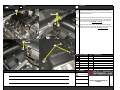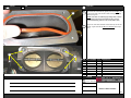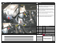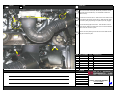
1
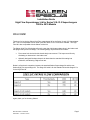
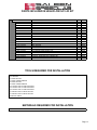
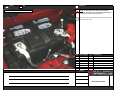
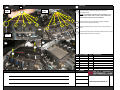
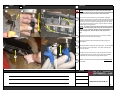
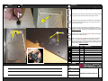
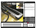
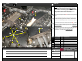
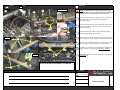
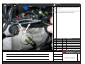
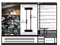
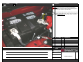
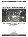
SALEEN SERIES VI.5 S/C HIGH FLOW LID UPGRADE
INSTALLATION MANUAL: Mustang GT / Saleen 281 / Saleen 302
2005 to 2010 Model Year
P/N: 10-8001-C19588A
Saleen Performance Vehicles
1-800-888-8945
www.saleen.com
STOP
IF YOU ARE NOT EXPERIENCED IN THE AREA
OF AUTOMOTIVE MECHANICS, WE
STRONGLY URGE THAT YOU REFER THIS
INSTALLATION TO A CERTIFIED INSTALLER
OR TECHNICIAN.
ENSURE THE VEHICLE PARKING BRAKE IS
ON AND THE TRANSMISSION IS IN PARK OR
IN GEAR WHEN WORKING ON IT.
Installation Guide
High Flow Supercharger Lid for Series VI & VI.5 Superchargers
2005 to 2010 Models
WELCOME!
Thank you for buying the Saleen High Flow supercharger lid for the Series VI and VI.5 Supercharger
kits. This lid is compatible with all model years the Series VI & VI.5 kits were available. The High
Flow lid is also compatible with the Saleen cold air kit.
The Saleen High Flow lid is designed in such a way that it eliminates obstructions in the intake track
that plagued the previous lid design. The following design improvements were made…
•
Front center bolt riser behind the throttle body was removed. This improves air flow by
eliminating an obstruction in the intake track.
•
Optimally designed lid shape channels air better than the standard lid creating less
turbulence, and allowing a higher flow rate.
Below is a flow bench comparison between the standard Saleen Supercharger lid and the new
Saleen High Flow supercharger lid. The Stage 6.0 Label is for the Standard lid and the Stage 6.5 is
for the High Flow lid.
Again, thank you for choosing Saleen!
Manual Created: 10/28/2010
Revision# 0 Revision Level A
Page I
Pre-Installation Precautions:
To help ensure the proper operation of your vehicle, follow the guidelines below:
IF YOU ARE NOT EXPERIENCED in the area of automotive mechanics, we strongly
urge that you refer this installation to a certified installer or technician.
STOP
PAY ATTENTION TO VEHICLE TYPE NOTATION because there are installation
steps in this manual that differ based on whether your vehicle is a 2005 to 2009 model
or a 2010 model*. There will be clear markings at the lower RH corner of the page
(A - C designations). Taking the time to read these instructions
along with following the notes will ensure a smooth, easy, and successful
installation**.
*This instruction manual consists of the two most likely vehicle types for this kit (Saleen Series VI and VI.5 Superchargers on a 2005
to 2010 Mustang). Saleen cannot anticipate what modifications may be done to every vehicle, so there may be an installation conflict
with some aftermarket equipment.
**This manual was created during the production process, using the Saleen 2010 S281 S/C as an example. Any form of aftermarket
body kits may require different or additional steps when removing body components (such as the headlamp) and may be
different then the instructions listed in this manual. If the vehicle does contain other aftermarket body components, contact that
aftermarket supplier for disassembly and assembly instructions.
Safety Precautions:
To help guarantee your safety, please follow the guidelines listed below:
NO SMOKING, FLAMES, OR SPARKS around the battery or fuel system. Batteries
can give off fumes that are flammable and may ignite if there is any form of spark or
open flame near it.
WEAR THE APPROPRIATE SAFTEY GEAR such as safety glasses and gloves
during the vehicle tear down and installation of new components. Always follow the
safety instructions that come with the tools you are using.
USE CAUTION AROUND VEHICLE when working on it. Make sure the vehicle is
turned OFF, is properly secured (in park or in gear with the parking brake on), and is
sitting on a level surface.
If a hoist or floor jack is required, make sure the vehicle is in park or in gear and the
parking brake on. If using a floor jack, make sure the vehicle is on a level surface,
the rear tires are chocked, and the vehicle is being supported by jack stands. Follow
ALL safety guidelines & operational instructions spelled out in the hoist or floor jack’s
owners manual. Failure to do so may result in serious injury.
Avoid wearing loose clothing or jewelry, as these items might get caught in moving
parts resulting in injury. When instructed to operate your vehicle, make sure you do
so in a well-ventilated area (to prevent carbon monoxide poisoning).
Be safe and use proper care and precautions. Saleen wants you to have a safe and rewarding
experience.
Page II
Table of Contents
A Strut Tower Brace Equipped Vehicles
B 2005 to 2009 Models
C 2010 Models
I. Introduction
Pg. I
II. Precautions (PLEASE READ CAREFULLY)
Pg. II
II. Table of Contents
Pg. III
III. Requirements
Pg. IV
Parts List
IV. Tear-Down Instructions
Battery Disconnection
A Strut Tower Brace Removal
B Intake Snorkel Removal (2005 to 2009 Models)
C Intake Snorkel Removal (2010 Models)
Throttle Body Removal
EVAP & Fuel System Disconnection
Supercharger Lid Removal
Fuel Rail Removal
Pg. 1
Pg. 2A
Pg. 3B
Pg. 4C
Pg. 5
Pg. 6
Pg. 7
Pg. 8
V. Parts Assembly & Modification Instructions
Supercharger Lid Assembly
Lid O-Ring Installation
Pg. 9
Pg. 10
VI. Installation Instructions
Supercharger Lid Installation
Fuel Rail Installation
A Strut Tower Brace Installation
ACT Sensor Removal & Plug Installation
ACT Harness Removal
Gauge Pod Harness Wiring (Optional)
TMAP Harness Installation
Supercharger Lid Snorkel Installation
Install Throttle Body
EVAP, PCV & Throttle Body Connections
B Intake Snorkel Installation (2005 to 2009 Models)
C Intake Snorkel Installation (2010 Models)
Battery Connection
Pg. 11
Pg. 12
Pg. 13A
Pg. 14
Pg. 15
Pg. 16
Pg. 17
Pg. 18
Pg. 19
Pg. 20
Pg. 21B
Pg. 22C
Pg. 23
VII. Post Installation Inspection
Post Installation Review
Pg. 24
Page III
PARTS INCLUDED IN HIGH FLOW S/C LID KIT
10-1607-B19560
06-1607-C09882
06-1607-B19559
00-9304-C19185
00-1607-C19548
06-1607-C18446
00-1607-C19550
00-1607-C19549
00-1607-C19547
00-1607-C19551
00-1607-C18833
00-9001-C18850
00-9001-C18849
06-1607-C18834
00-1702-C145400
TBD
00-9004-C002270
00-2003-C104480
08-1704-B15501
00-1703-C070820
00-1704-C092600
00-1704-C153070
SERIES 6.5 SUPERCHARGER HIGH FLOW LID UPGRADE
GASKET, INLET TUBE '05 MUSTANG
INLET SNORKEL, SERIES 6.5 SUPERCHARGER MACHINED
VIBRA STOP HIGH TEMP, 30cc
O-RING .070"x6.00" I.D.
LID, SUPERCHARGER MODULAR
HSCS M8x16 LG SS
HSCS M8x40 LG SS
HSCS M8x35 LG SS
BHCS M8x12 LG SS
STOP, 3/4" BUNA-N RUBBER
CAPSCRW SCKT HD M4x0.7x16mm
CAPSCRW FLT HD M6x1.0x16mm
SPACER, INTERCOOLER RETAINING
TMAP SENSOR
CAPSCRW, SCKT HD M5x0.8x20mm
WASHER FLAT M5 ST
PLUG SOCKET HEAD 3/8 NPT NI PL
HARNESS, S331 TMAP SENSOR EXTENSION
HEAT SHRINK SUAL WALL 1/4" BLK
18 GAUGE, SEAMLESS BUTT CONNECTOR
SLEEVING, CONVOLUTED 1/4" BLK
1
1
1
1
1
1
6
4
2
1
1
1
1
1
1
2
2
1
1
5
2
8
EACH
EACH
EACH
EACH
EACH
EACH
EACH
EACH
EACH
EACH
EACH
EACH
EACH
EACH
EACH
EACH
EACH
EACH
EACH
INCH
EACH
INCH
TOOLS REQUIRED FOR INSTALLATION
ALLEN WRENCH SET
19mm WRENCH
1/4" DRIVE RATCHET
1/4" DRIVE TORQUE WRENCH
3/8" DRIVE RATCHET
3/8" DRIVE TORQUE WRENCH
17mm SOCKET FOR 3/8" DRIVE RATCHET
13mm SOCKET FOR 1/4" DRIVE RATCHET
12mm SOCKET FOR 1/4" DRIVE RATCHET
8mm SOCKET FOR 1/4" DRIVE RATCHET
7mm SOCKET FOR 1/4" DRIVE RATCHET
LIGHTER OR TORCH
MATERIALS REQUIRED FOR INSTALLATION
VIBRA-TITE 46025 PTFE PIPE SEALANT
Page IV
TORQUE
ITEM
OPERATION
2010 MODEL SHOWN - 2005 TO 2009 TYPICAL
NOTICE: No smoking, flames, or sparks around the battery.
Batteries can give off fumes that are flammable and may ignite if
there is any form of spark or open flame near it.
10
10
ITEM
Remove the red boot, and disconnect battery positive terminal from the
battery with an 8mm socket.
PART NUMBER
QTY. DESCRIPTION
TORQUE
NOTES:
PROCESS
PAGE
DISCONNECT BATTERY
1
TORQUE
ITEM
OPERATION
10
Remove the four 13mm nuts (two per strut tower brace bracket), and lift
each bracket off of the strut tower.
20
NOTICE: PICTURE 10 is from a vehicle equipped with the Saleen
N2 Adjustable Suspension (P/N: 06-1300-A19349). If the vehicle is
equipped with this suspension, the upper strut mount nuts will be
12mm.
10
20
Disconnect one of the strut tower bar brackets from the bar. The
bracket is attached with an Allen head bolt and a 17mm nut.
30
Carefully slide the strut tower brace through the gap in the supercharger
lid. The end with the removed bracket will be slid through the lid.
NOTICE: It is very easy to scratch the strut tower bar when sliding
it through the lid. Remove the bar with care.
30
ITEM
PART NUMBER
QTY. DESCRIPTION
TORQUE
NOTES:
PROCESS
PAGE
REMOVE STRUT TOWER BRACE
STRUT TOWER EQUIPPED VEHICLES
A
2
TORQUE
ITEM
OPERATION
10
10
Pull the red tab on the top of the MAF connector away from the air box
lid to un-lock the connector. Depress the tab on the top of the
connector, and disconnect.
20
Disconnect the crankcase vent tube from the snorkel (just forward of the
throttle body). Push on the green locking tab, and pull the vent tube
away from the snorkel.
30
With a flat blade screwdriver, loosen the clamp that secures the air box
snorkel to the throttle body.
40
Undo the two clasps (facing the passenger compartment) that lock the
air box lid to the air box. Slide the lid tabs out of the air box.
50
Lift the intake assembly (snorkel and air box lid together) out of the
vehicle and set aside.
20
30
40
10
ITEM
PART NUMBER
QTY. DESCRIPTION
TORQUE
NOTES:
PROCESS
PAGE
REMOVE AIR INTAKE SNORKEL
2005 to 2009 MODELS
B
3
TORQUE
ITEM
OPERATION
10
20
30
Pull the red tab on the top of the MAF connector away from the air box
lid to un-lock the connector. Depress the tab on the top of the
connector, and disconnect.
Disconnect the crankcase vent tube from the snorkel (just forward of the
throttle body). Push on the green locking tab, and pull the vent tube
away from the snorkel.
30
With a flat blade screwdriver, loosen the clamp that secures the air box
snorkel to the throttle body. Slide the intake snorkel off of the throttle
body.
40
Use a tension clamp tool to open up the clamp securing the breather
tube to the intake snorkel. Disconnect the tube from the snorkel and set
to the side.
40
10
50
20
Release the 2 clasps holding the air box lid to the air box. Remove the
air box lid and inlet snorkel.
50
ITEM
PART NUMBER
QTY. DESCRIPTION
TORQUE
NOTES:
PROCESS
PAGE
REMOVE AIR INTAKE SNORKEL
2010 MODELS
C
4
TORQUE
ITEM
OPERATION
20
10
Disconnect the throttle position sensor electrical connector by sliding the
red shield on the connector towards the front of the car. Push down on
the now exposed tab, and pull the connector towards the front of the
vehicle to remove.
20
Disconnect the electronic throttle control electrical connector by pulling
the red locking tab outward. Pull the connector outward.
30
Remove the four 10mm bolts securing the throttle body. Remove the
throttle body.
40
Remove the orange throttle body gasket from the lid (between the
throttle body and lid), the gasket will be re-used.
NOTICE: If the motor is a relatively high mileage motor, a brand
new replacment may need to be aquired from Ford. It is the
standard throttle body gasket for a 4.6L 3V GT (2005 to 2010).
10
30
30
ITEM
PART NUMBER
QTY. DESCRIPTION
TORQUE
NOTES:
PROCESS
PAGE
REMOVE THROTTLE BODY
5
TORQUE
ITEM
OPERATION
1 OF 8 SHOWN
NOTICE: No smoking, flames, or sparks around the fuel system.
The fuel line and fuel rail can give off fumes that are flammable and
may ignite if there is any form of spark or open flame near it.
40
10
20
10
Disconnect the PCV tube from the driver (LH) side of the supercharger
assembly lid. The fitting is just rearward of the throttle body. Slide the
green locking collar to unlock and pull the hose off of the lid fitting.
20
Disconnect the PCV tube from the driver (LH) side of the supercharger
assembly lid. The fitting is just rearward of the throttle body. Press in
the white collar and pull the hose off of the lid fitting.
30
Disconnect the fuel rail electrical connector from the fuel rail module
located on the driver (LH) side. Remove the rubber hose from the
module located on the opposite side of the connector.
40
Remove the safety clip from the fuel line connector on the fuel rail.
30
50
60
RH SIDE
80
50
70
LH SIDE
2005 TO 2009 SHOWN ABOVE. 2010 VEHICLES DO NOT
RETAIN THE ALTERNATOR HARNESS IN THIS MANNER
Place the fuel line disconnect tool on the fuel rail side of the fuel rail.
Slide the fuel line disconnect tool towards the rear of the vehicle until the
tool locks in place. Disconnect the fuel line.
60
Disconnect the 8 fuel injector electrical connectors (gray) from the fuel
injectors.
70
2005 to 2009: Detach the two wiring harness retainers from the fuel rail
mounting stud bolts and position the harness to the side.
80
Remove the four 8mm fuel rail stud bolts and save them (they will be
used later).
80
TORQUE
NOTES:
PROCESS
PAGE
DISCONNECT EVAP & FUEL
SYSTEM
6
TORQUE
RH SIDE
SHOWN
ITEM
OPERATION
LH SIDE
SHOWN
10
10
10
Remove the fourteen 12mm bolts holding the lid to the main
supercharger housing.
NOTICE: One 12mm bolt at the back of the supercharger is very
difficult to get to with the cowl over-hang. A swivel socket and
extension may be needed to acccess and remove.
3 BOLTS
CIRCLED
20
Pull each fuel rail up off of the supercharger (pulling all eight fuel
injectors out of the supercharger housing).
30
Lift the supercharger lid (with fuel rails) off of the main supercharger
housing.
40
Once the lid is removed, make sure the old lid gasket is removed. Wipe
the gasket mating surface with a lint free rag.
40
20
30
20
ITEM
PART NUMBER
QTY. DESCRIPTION
TORQUE
NOTES:
PROCESS
PAGE
REMOVE SUPERCHARGER LID
7
TORQUE
ITEM
10
10
OPERATION
20
NOTICE: No smoking, flames, or sparks around the fuel system.
The fuel line and fuel rail can give off fumes that are flammable and
may ignite if there is any form of spark or open flame near it.
10
Remove four of the fuel injectors from one fuel rail with a flat blade
screwdriver. Set the tip of the screwdriver between the flange in the fuel
rail (where the fuel injector connects), and one of the ears of the injector
retaining clip. Use the screwdriver to disengage the tab on the clip ear,
and pry away from the injector connector. Once the clips are removed,
pull each injector out of the fuel rail.
NOTICE: The injector clips have tension on them. When removing
them with a screwdriver, they may want to pop off the injector and
go flying. Try to contain the clips when removing and make sure
to wear safety glasses. Save the injector clips, they will be reused.
20
Once the four fuel injectors are removed from one fuel rail, rotate the
fuel rail with the removed injectors 90 degrees.
30
Slide the fuel rail with the removed injectors through the gap in the
supercharger lid.
40
Install the fuel injector retainer clips onto each injector. The clip will slide
into the channel on top of each injector. The 2 ears of each clip will
need to face upward.
40
50
50
30
60
Once there is a clip on each injector, insert each injector into the fuel
rail. Make sure the connector portion of each injector faces outboard,
and that both ears of the locking clip engage the fuel rail port.
Rotate the fuel rail back into position (Position before OPERATION 20),
and set aside.
TORQUE
NOTES:
PROCESS
PAGE
REMOVE FUEL RAIL FROM LID
8
TORQUE
ITEM
OPERATION
10
10
Assemble the intercooler stop by placing the rubber foot (A) over the end
of the aluminum spacer (B) that is drilled and tapped for an M4 thread.
20
Apply Vibra Stop to the threads of the M4x16mm socket head cap screw
(C). Tighten the M4 screw until the rubber stop begins to deform.
30
Apply Vibra Stop to the tapered face of the M6x16mm countersunk bolt
(D), insert into shaker supercharger lid (E). Do not wait for the Vibra
Stop to dry before inserting.
40
Thread the intercooler stop assembly onto the M6 bolt after applying
Vibra Stop to the threads. Do not wait for the Vibra Stop to dry. Torque
to 89 Lb-in +/- 13 Lb-in. Wipe the excess sealant off of the head of the
countersunk bolt.
50
Apply Vibra stop to the two allen head bolts (G). Slide the bolts through
the two holes in the TMAP sensor (H).
60
Slide the two washers (I) (one washer per bolt) onto the exposed bolt
threads. The washers will installed in such a way that they will sit
between the TMAP sensor and the lid (to space the TMAP off of the lid.
Install the TMAP so that the connector faces the nearest edge of the lid.
Torque each bolt to 40 Lb-in +/- 6 Lb-in.
20
60
1
2
ITEM
PART NUMBER
A
B
C
D
E
F
G
H
I
00-1607-C18833
QTY. DESCRIPTION
1
Stop, 3/4IN Buna-N Rubber
06-1607-C18834
1
Spacer, Intercooler Retain
00-9001-C18850
1
Caspcrw Sckt HD M4x0.7x16mm
00-9001-C18849
1
Capscrw, FLT HD M6x1.0x16mm
06-1607-C18446
1
Lid, Supercharger Modular
00-9304-C19185
1
Vibra Stop High Temp
00-9001-C094960
2
Capscrw Sckt HD M4x0.7x12mm
00-1702-C14540
1
TMAP Sensor
00-9004-C002270
2
Washer Flat M5 ST
TORQUE
NOTES:
1
89 +/- 13 Lb-in
2
40 +/- 6 Lb-in
PROCESS
PAGE
ASSEMBLE SUPERCHARGER LID
9
TORQUE
ITEM
OPERATION
10
Using a clean cloth rag and brake cleaner, clean the interior of the intake
snorkel, and the machined mating faces at either end. Let air dry or
blow out with compressed air if available.
20
Apply silicone O-ring lubricant to the large O-ring (A).
30
40
Install the large O-ring over the slotted end of the supercharger intake
snorkel (B). The O-ring will sit in the groove milled in the perimeter of
the snorkel. Be careful to stretch the O-ring as little as possible while
installing it. The fit may appear a loose once it is sitting in its groove.
Gently run your finger around the O-ring to seat it into its groove. Push
any access towards the back face as shown. Make sure the corners are
seated well.
30
ITEM
PART NUMBER
QTY. DESCRIPTION
A
B
06-1607-C19548
1
O-Ring .070" x 6.00" I.D.
06-1607-B19559
1
Inlet Snorkel, Series 6.5 SC Machined
TORQUE
NOTES:
PROCESS
PAGE
INSTALL SUPERCHARGER
SNORKEL O-RING
10
TORQUE
ITEM
OPERATION
NOTICE: The TMAP sensor and harness will be pointed in the
reverse direction then what was instructed on Page 9 (pointing
towards the driver side instead of the passenger side). Disregard
sensor orientation in the following pages. It can be installed facing
the driver side, but Saleen recommends the sensor face the
passenger side for ease of connector accessibility.
20
10
Retrieve the supercharger lid gasket (A) and set it onto the supercharger
housing.
20
Lower the assembled supercharger lid onto the supercharger housing.
The TMAP will be facing upward and the theaded on stud with rubber
stop will face downward (holding the back of the intercooler in place).
30
Apply Vibra Stop to the threads of the six allen head bolts (B). Install the
six bolts to secure the supercharger lid to the housing. Torque each bolt
to 18 Lb-ft +/- 2.7 Lb-ft. Follow the torque order shown in PICTURE 30.
40
Apply Vibra Stop to the threads of the one low profile allen head bolt (C).
Install the bolt into the front center most mounting hole in the
supercharger lid. Torque the bolt to 18 Lb-ft +/- 2.7 Lb-ft.
10
3
40
1
1
6
1
30
5
2
ITEM
PART NUMBER
QTY. DESCRIPTION
A
B
C
D
06-1607-C09882
1
Gasket Inlet Tube
00-1607-C19550
6
HSCS M8x16 LG SS
00-1607-C19551
1
BHCS M8x12 LG SS
00-9304-C19185
1
Vibra Stop High Temp
4
TORQUE
NOTES:
1
18 +/- 2.7 Lb-ft
PROCESS
PAGE
INSTALL SUPERCHARGER LID
11
TORQUE
ITEM
OPERATION
1 OF 8 SHOWN
30
10
NOTICE: No smoking, flames, or sparks around the fuel system.
The fuel line and fuel rail can give off fumes that are flammable and
may ignite if there is any form of spark or open flame near it.
20
10
Set the fuel rail assembly onto the supercharger. Press each fuel rail
downward and make sure each fuel injector is seated into the
supercharger housing.
20
Connect the fuel rail electrical connector to the fuel rail module located
on the driver (LH) side. Press the connector into the module until the
connector is fully seated.
30
Slide the fuel rail vacuum line back onto the fuel rail module (fitting
located on the opposite side of the connector).
40
Press the fuel line onto the fuel rail fitting located on the driver (LH) side.
Press the locking clip over the connection to lock the fuel line into place.
50
Connect the main engine harness to each of the 8 fuel injectors. Press
each grey connector onto the fuel injector until it clicks into place.
60
Re-install the four fuel rail bolts. (the two stud bolts are installed on the
passenger (RH side). Torque each bolt to 91 Lb-in +/- 13.6 Lb-in.
70
2005 to 2009: Re-attach the two wiring harness retainers to the fuel rail
mounting stud bolts.
40
50
RH SIDE
1
60
LH SIDE
70
2005 TO 2009 SHOWN ABOVE. 2010 VEHICLES DO NOT
RETAIN THE ALTERNATOR HARNESS IN THIS MANNER
1
60
TORQUE
NOTES:
1
91 +/- 13.6 Lb-in
PROCESS
PAGE
INSTALL FUEL RAIL
12
TORQUE
10
ITEM
OPERATION
RH SIDE SHOWN - LH TYPICAL
10
Re-assemble the strut tower bracket to the strut tower bar. The allen
head bolt with washer will face forward with a washer, lock washer, and
nut facing towards the blukhead.
20
Place each strut tower bracket back onto the strut tower (over the strut
studs). Re-install and tighten the four 13mm nuts (two per strut tower)
and torque to 26 Lb-ft +/- 3.9 Lb-ft.
NOTICE: PICTURE 20 is from a vehicle equipped with the Saleen
N2 Adjustable Suspension (P/N: 06-1300-A19349). If the vehicle is
equipped with this suspension, the upper strut mount nuts will be
12mm.
ITEM
PART NUMBER
QTY. DESCRIPTION
20
1
TORQUE
NOTES:
1
26 +/- 3.9 Lb-ft
PROCESS
PAGE
INSTALL STRUT TOWER BRACE
STRUT TOWER EQUIPPED VEHICLES
A
13
TORQUE
ITEM
OPERATION
10
10
20
Disconnect the engine harness ACT connector from the ACT sensor.
To disconnect, depress the tab on the top of the connector and pull to
remove.
20
Using a 19mm wrench, remove the ACT sensor from the supercharger
housing (located on the driver side near the front of the supercharger).
30
Apply PTFE Instant Pipe Sealant to the threads of the supplied Allen
plug (A).
NOTICE: Saleen recommends the use of Vibra-Tite 46025 PTFE
Pipe Sealant. Loctite 567 or an equivalent can be used as a
substitute.
40
Install the plug with an Allen wrench. Make sure the plug is fully seated.
30
40
ITEM
PART NUMBER
A
00-2003-C104480
QTY. DESCRIPTION
1
Plug, SCKT HD 3/8 NPT NI-PL
TORQUE
NOTES:
PROCESS
PAGE
REMOVE ACT SENSOR &
PLUG CASE
14
TORQUE
ITEM
OPERATION
10
Remove the electrical tape where the ACT sensor harness meets the
engine harness.
20
Peel back the wiring convolute and cut the gray and gray with red stripe
wires on the engine harness side of the butt connectors.
20
ITEM
PART NUMBER
QTY. DESCRIPTION
TORQUE
NOTES:
PROCESS
PAGE
REMOVE ACT HARNESS
15
TORQUE
ITEM
OPERATION
NOTICE: These steps are only required if you will be connecting
the Saleen boost and air charge temp gauge kit.
10
Using wire cutters, cut the gray wire with single pin connector off at the
ACT sensor connector. Strip approximately 1/4in of insulation from the
end of the gray wire. The wire will be inserted into the butt connector
that will be used to connect the gray wires coming from the engine and
TMAP harnesses on the next page.
20
Splice the single pin connector (with attached gray wire removed in
OPERATION 10) to the gray wire butt splice on Page 17.
ITEM
PART NUMBER
QTY. DESCRIPTION
A
TORQUE
NOTES:
PROCESS
PAGE
TRANSFER GAUGE POD
CONNECTOR FROM ACT
HARNESS TO TMAP HARNESS
MODELS WITH A GAUGE POD KIT
16
TORQUE
ITEM
OPERATION
10
Retrieve the TMAP sensor wiring harness (A), plug the 5-pin connector
into the TMAP sensor, and route the harness around the front of the
supercharger housing.
20
Untape the wiring convolute where the gray, gray with red stripe, and
brown wires come out of the convolute. Tuck the brown wire back into
the convolute, and retape the convolute.
30
Cut 3.5in from the gray and gray with red stripe wires, strip 1/4in of
insulation off of each one, and crimp a butt connector (B) onto the end of
both wires.
40
Cut two pieces of heat shrink off of the supplied length (C) and put one
piece over the gray and gray with red wires coming from the driver side
engine wiring harness.
50
Strip 1/4in of insulation off of the gray and gray with red stripe wires
coming from the driver side engine wiring harness. Crimp the TMAP
wires to the engine wiring harness wires, gray to gray and gray with red
stripe to gray with red stripe.
60
Shink the heat shrink using a small torch, lighter, or other heat source.
Cut a 6in piece of 1/4in wiring convolute (D) from the supplied length and
slip it over the exposed wires. Tape at both ends.
70
Use a zip tie and tie the connector coming from the TMAP harness in
place. It will not be used.
80
GAUGE POD EQUIPPED VEHICLES: Connect the 1 pin connector
from the gauge pod harness to the 1 pin connector removed from the
ACT harness on Page 16.
10
80
ITEM
PART NUMBER
A
B
C
D
08-1704-B15501
QTY. DESCRIPTION
1
Harness, TMAP Sensor Ext
00-1704-C092600
2
18 Gauge, Butt Connector
00-1703-C070820
5"
Heat Shrink, Dual Wall 1/4" BLK
00-1704-C153070
8"
Sleeving, Convoluted 1/4" BLK
TORQUE
NOTES:
PROCESS
PAGE
INSTALL TMAP HARNESS
17
TORQUE
ITEM
OPERATION
10
Lightly place the supercharger lid snorkel onto the supercharger lid.
Lightly tap the back of the lid (portion near the bulkhead) downward till
the snorkel seats to the lid.
20
Obtain the four Allen head bolts (A) (with a collar above the threads).
Apply Vibra Seal to the threads. Install three bolts on the passenger
side rear corner of the lid snorkel and one bolt on the driver side rear
corner. Torque each bolt to 18 Lb-ft +/- 2.7 Lb-ft.
30
Obtain the two Allen head bolts (B). Apply Vibra Seal to the threads.
Install the two bolts at the front of the supercharger (one on each side of
the "Saleen" logo). Torque each bolt to 18 Lb-ft +/- 2.7 Lb-ft.
20
1
20
10
1
1
30
ITEM
PART NUMBER
QTY. DESCRIPTION
A
B
C
00-1607-C19549
4
HSCS M8x40 LG SS
00-1607-C19547
2
HSCS M8x35 LG SS
00-9304-C19185
1
Vibra Stop High Temp
TORQUE
NOTES:
1
18 +/- 2.7 Lb-ft
PROCESS
PAGE
INSTALL SUPERCHARGER LID
SNORKEL
18
TORQUE
ITEM
OPERATION
10
20
Insert the take-off Ford throttle body gasket (removed on Page 5), into
the groove in the front of the inlet tube. Make sure the gasket is fully
seated into the groove.
NOTICE: If the motor is a relatively high mileage motor, a brand
new replacment may need to be aquired from Ford. It is the
standard throttle body gasket for a 4.6L 3V GT (2005 to 2010).
20
Using the four 10mm bolts, install the stock throttle body onto the inlet
assembly. Tighten the bolts to 91 Lb-in +/- 13.6 Lb-in with a torque
wrench.
30
30
ITEM
1
PART NUMBER
QTY. DESCRIPTION
1
TORQUE
NOTES:
1
91 +/- 13.6 Lb-in
PROCESS
PAGE
INSTALL THROTTLE BODY
19
TORQUE
ITEM
OPERATION
10
20
10
30
20
30
40
Plug in the throttle control electrical connector into the passenger (RH)
side of the throttle body. Press the plug onto the throttle body connector
until it is fully seated, and then slide the red locking tab towards the
throttle body to lock the connector into place.
Connect the throttle position connector to the driver (LH) side of the
throttle body. Press the plug onto the throttle body connector until it is
fully seated, and then slide the red locking tab towards the throttle body
to lock the connector into place.
Connect the PCV tube to the driver (LH) side of the supercharger
assembly lid. The fitting is just rearward of the throttle body. Press the
tube onto the fitting until it clicks into place.
Connect the EVAP canister vapor tube into the driver (LH) side of the
supercharger assembly lid. The fitting is located rearward of the PCV
tube. Press the tube onto the fitting until it clicks into place.
40
ITEM
PART NUMBER
QTY. DESCRIPTION
TORQUE
NOTES:
PROCESS
PAGE
MAKE EVAP, PCV & THROTTLE
BODY CONNECTIONS
20
TORQUE
ITEM
OPERATION
30
10
Retrieve the air intake snorkel (with attached lid) and slide the throttle
body portion onto the throttle body. Use a flat blade screwdriver to
tighten the clamp.
20
Secure the air box lid to the air box. Slide the lid over the tabs in the air
box and press to the lid down onto the air box. Make sure both clasps
on the air box (facing the passenger compartment) are fully engaged.
30
Re-connect the MAF pigtail to the sensor. Press the MAF connector
onto the sensor. Slide the red locking tab on the connector towards the
sensor to lock the connector in place.
40
Press the end of the passenger side vent tube onto the intake snorkel
fitting until it "clicks" into place.
40
10
20
30
ITEM
PART NUMBER
QTY. DESCRIPTION
TORQUE
NOTES:
PROCESS
PAGE
INSTALL AIR INTAKE SNORKEL
2005 to 2009 MODELS
B
21
TORQUE
ITEM
OPERATION
10
20
10
Retrieve the air intake snorkel (with attached lid) and slide the throttle
body portion onto the throttle body. Use a flat blade screwdriver to
tighten the clamp.
Secure the air box lid to the air box. Slide the lid over the tabs in the air
box and press to the lid down onto the air box. Make sure both clasps
on the air box (facing the driver side fender) are fully engaged.
30
Use a tension clamp tool to open up the clamp securing the breather
tube to the intake snorkel. Slide the tube back into the intake snorkel
and re-secure the clamp.
40
Re-connect the MAF pigtail to the sensor. Press the MAF connector
onto the sensor. Slide the red locking tab on the connector towards the
sensor to lock the connector in place.
30
40
50
50
Press the end of the passenger side vent tube onto the intake snorkel
fitting until it "clicks" into place.
20
ITEM
PART NUMBER
QTY. DESCRIPTION
TORQUE
NOTES:
PROCESS
PAGE
INSTALL AIR INTAKE SNORKEL
2010 MODELS
C
22
TORQUE
ITEM
OPERATION
NOTICE: No smoking, flames, or sparks around the battery.
Batteries can give off fumes that are flammable and may ignite if
there is any form of spark or open flame near it.
10
10
1
ITEM
Connect the positive battery cable to the positive battery post ( The post
nearest the passenger (RH) fender). Using an 8mm socket, tighten the
clamp to 71 Lb-in +/- 10.6 Lb-in with a torque wrench. Re-cover the
clamp with the red boot.
PART NUMBER
QTY. DESCRIPTION
TORQUE
NOTES:
1
71 +/- 10.6 Lb-in
PROCESS
PAGE
CONNECT BATTERY
23
Post-Installation Review
Please take the time to read the information provided. If you are installing this kit, and not the vehicle
owner, please keep this page with the vehicle for the vehicle owner to review.
Post-Installation Review:
• Make sure that all electrical connections have been made
•
Check the vehicle for any coolant or fuel leaks
•
Verify that the intercooler water pump is running when the engine is running.
•
Verify that all hazard lights (turn signals, parking lights, fog lights, etc…) are working properly.
Contact Information:
If you have any additional questions or concerns about your new Saleen supercharger lid, please feel
free to contact us.
•
Tech Support: 1-800-888-8945
Again, Saleen would like to thank you for buying a Saleen High-Flow Supercharger lid for your Series
VI & VI.5 Supercharger Kit. We hope you enjoy your new product, and will consider us for all your
future aftermarket needs.
Page 24