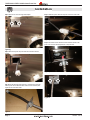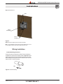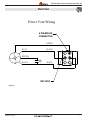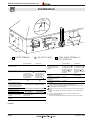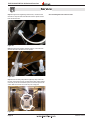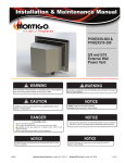
1
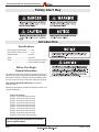
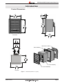
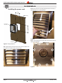
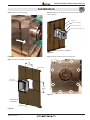
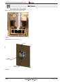
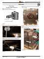
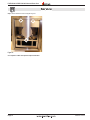
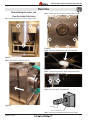
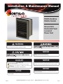
Installation & Maintenance Manual
PVHFL58-300 &
PVHFL510-300
5/8 and 5/10
Horizontal Flush
Louvered
Power Vent
WARNING
NOTICE
PVHEX510-300 power vent is approved for use with Montigo R520, R520-ST,
R620-ST, R720, and R820.
If the information in these instructions is not followed exactly, a fire or explosion
may result causing property damage, personal injury or death.
NOTICE
PVHEX58-300 power vent is approved for use with Montigo R320, R320-ST, R420,
R420-ST, and RP620.
NOTICE
Installer: Leave this manual with the appliance.
Consumer: Retain this manual for future reference.
NOTICE
NOTICE
DANGER
PVVEX58-300 power vent is approved for use with Montigo R320, R320-ST, R420,
R420-ST, and RP620.
IF YOU SMELL GAS
Blank
Blank
Flammable materials
Explosion risk
Toxic
Corrosive
Danger overhead crane
Fork lift trucks
High voltage
Do not try to light any appliance.
Do not touch any electrical switch; do not use any phone in your building.
Immediately call your gas supplier from a neighbor's phone. Follow the gas
supplier's instructions.
If you cannot reach your gas supplier, call the fire department.
Blank
Flammable materials
Explosion risk
Toxic
Corrosive
Danger overhead crane
Fork lift trucks
High voltage
General Warning
Laser Radiation
Biohazard
Oxidising
Hot surface
Danger of entrapment
Danger of death
Corrosive
Danger overhead crane
Fork lift trucks
Hot surface
Flammable materials
Explosion risk
General Warning
Laser Radiation
Biohazard
Slippery floor
Watch your step
Irritant
Toxic
Oxidising
Cutting
PVVEX510-300 power vent is approved for use with Montigo R520, R520-ST,
R620-ST, R720, and R820.
NOTICE
This power vent is approved for use with Montigo fireplaces only and is certified to
ANSI Z21.50 / CSA 2.22 vented gas fireplace standard along with the fireplace.
High voltage
Danger of entrapment
Danger of death
High temperatures
Glass hazard
Danger of suffocation
Hot surface
Danger of entrapment
Danger of death
Glass hazard
Danger of suffocation
Battery hazard
Rotating parts
Blank
General Warning
Laser Radiation
Biohazard
Irritant
Slippery floor
Watch your step
Cutting
High temperatures
Gas bottles
Watch for
falling objects
Explosion
risk
Electricity
Danger for cutter
Entrapment hazard
Corrosive
Danger overhead crane
Flammable materials
Toxic
Oxidising
Fork lift trucks
High voltage
Glass hazard
Danger of suffocation
Irritant
Slippery floor
Watch your step
Cutting
High temperatures
Gas bottles
Watch for
falling
objectsfield
Strong
magnetic
Electricity
Danger for cutter
Entrapment hazard
Battery hazard
Rotating parts
Low temperature
Optical radiation
Laser Radiation
Biohazard
Non ionizing
radiation
Oxidising
Radiation
General Warning
Hot surface
Hazardous to the
Environment
Danger of entrapment
Danger of harming
your hands
Danger of death
Gas bottles
Watch for
falling objects
Strong magnetic field
Electricity
Danger for cutter
Optical radiation
Entrapment hazard
Battery hazard
Non ionizing
radiation
Radiation
Hazardous to the
Environment
Danger of harming
your hands
Irritant
Slippery floor
Watch your step
Cutting
High temperatures
Glass hazard
Danger of suffocation
Low temperature
Strong magnetic field
Optical radiation
Non ionizing
radiation
Radiation
Hazardous to the
Environment
Danger of harming
your hands
Gas bottles
Watch for
falling objects
Electricity
Danger for cutter
Entrapment hazard
Battery hazard
Rotating parts
Low temperature
Rotating parts
NOTICE
NOTICE
PVHFL510-300 power vent is approved for use with Montigo R520, R520-ST,
R620-ST, R720, and R820.
PVHFL58-300 power vent is approved for use with Montigo R320, R320-ST, R420,
R420-ST, and RP620.
XG0519
Canadian Heating Products Inc. Langley, BC V4W 4A1 | Montigo Del Ray Corp. Ferndale, WA 98248
070714
PVHFL58-300 & PVHFL510-300 Horizontal Power Vent
Safety Alert Key
Introduction
Specifications
Pipe Dimensions PVHFL58-300 . ........... 5"/8"
Pipe Dimensions PVHFL510-300 . ......... 5"/10"
Maximum Airflow: .......................... 300 CFM
Speed: ........................................... 2700 RPM
Power:............................................. Connect to fireplace control box
. ........................................... Refer to fireplace rating plate
Before Your Begin
General Information
This installation guide covers installation of the External Power Vent
System only. This system is designed to allow installation of gas fireplaces
that cannot be done with a standard Direct Vent gas fireplace installation. Only for use on R-Series, R-Series See-Through and RP-Series.
ONLY USE WITH APPROVED FIREPLACES - see fireplace installation manual.
Read through the fireplace's installation & maintenance manual, as it
must also be adhered to.
Power Cord Harnesses:
EPVH10 - 10 foot power cord and harness
EPVH20 - 20 foot power cord and harness
EPVH30 - 30 foot power cord and harness
EPVH40 - 40 foot power cord and harness
EPVH50 - 50 foot power cord and harness
EPVH60 - 60 foot power cord and harness
EPVH70 - 70 foot power cord and harness
EPVH80 - 80 foot power cord and harness
EPVH90 - 90 foot power cord and harness
EPVH100 -100 foot power cord and harness
For vent configurations and power vent locations,
refer to fireplace manual. Page 2
XG0519 - 070714
1
"
4
311
12
1
"
4
311
12
1
21 "
1
8
21 "
8 Dimensions
Product
538
538
3
"
4
476
18
PVHFL58-300 & PVHFL510-300 Horizontal Power Vent
Introduction
3
"
4
476
18
2"
50
1
"
4
565
22
5
1
22 " 24 8 "
4
565 627
2"
50
5
"
8
627
24
5
"
8
421
Front View
16
5
"
8
421
16
Side View
PVHEX10-300
10"
254
PVHEX58-300
8"
203
Back Cover / Collar
Outer Assembly
5"
126
1
"
4
311
12
Inner Assembly
1
"
8
538
21
Louver Assembly
Top View
Figure
Step
1 1. PVHFL58-300 (Tolerance ± ⅛") [mm]
1) Construct the support framing within the
measurements as shown here. The
dimensions shown here are minimum
dimensions to attach the Outer Assembly too.
XG0519 - 070714
Framin
3
"
4
476
18
Page 3
PVHFL58-300 & PVHFL510-300 Horizontal Power Vent
Installation
Installing the power vent
Step 2: Remove the louver assembly by lifting the bottom end forward and
then dropping the door out of the top latches.
3
"
4
476
18
Framing
Outer Can
Assembly
1
"
4
565
22
Figure 3a.
Wall Board
Step 3: To remove the inner can from the outer can remove the 8 screws on
the back of the termination.
Figure 2. Framing dimensions
Step 1: Unpack power vent from box. Remove two screws from bottom of the
door. Hold louver assembly securely so it does not fall.
Figure 3.
Page 4
Figure 3b.
XG0519 - 070714
PVHFL58-300 & PVHFL510-300 Horizontal Power Vent
Installation
Step 4: Slide the inner can out by pulling
Step 6: Slide the inner can assembly into the outer can assembly from the
inside of the house.
Structure
Outer Can Assembly
Inner Can Assembly
Power Cord from Power Vent
All framing shown is combustible
Figure 3e.
Step 7: Screw inner can back to outer can using 8 screws.
Figure 3c.
Step 5: Screw outer can assembly into the wall
3
"
4
476
18
Framing
Outer Can
Assembly
1
"
4
565
22
Figure 3f.
All framing shown
is combustible
Wall Board
Figure 3d.
XG0519 - 070714
Page 5
PVHFL58-300 & PVHFL510-300 Horizontal Power Vent
Installation
Step 8: Remove two screws securing electrical plate.
Step 11: Attach the power cable from the power vent to the control cable.
Figure 3j.
Step 12: Push all the excess cable back into the electrical channel of the
power vent. Screw the electrical plate back on the power vent.
Figure 3g.
Step 9: Remove the power vent power cable from inside the electrical
channel.
Figure 3j.
Figure 3h.
Step 10:Take the electrical harness [EPVH-10-100] that will communicate
with the power vent and attach the strain relief for it to the electrical plate.
Tighten the nut on the strain relief.
Figure 3k.
Figure 3i.
Page 6
XG0519 - 070714
PVHFL58-300 & PVHFL510-300 Horizontal Power Vent
Installation
Step 13: Reinstall the door.
Tabs
Front Grill into the Out Can
y by inserting top tabs into the
ame and securing the bottom with
s provided.
Louver
Assembly
Screw
Locations
Figure 3l.
Step 14: Connect vent pipe to power vent collar as required.
Note: If you are intending to service power vent from inside the house, use a
4-foot flex pipe to allow for easy removal of pipe from power vent.
Wiring Installation
Conduit & Wiring clearances
Connect the power vent harness as outlined. Connect the wiring to
the fireplace as outlined in the schematic shown in figure 4a. Ensure
that the proper clearances are maintained for the wiring and conduit.
When installing the wiring it must never run above the vent run and it
must be at least 1" clear of all venting.
Wire
1” Clearance
Figure 4. Conduit and Wiring
XG0519 - 070714
Page 7
PVHFL58-300 & PVHFL510-300 Horizontal Power Vent
Service
Power Vent Wiring
6 PIN MOLEX
CONNECTOR
GREEN
BLUE
BLACK
BROWN
C
BLACK
WHITE
KEY WAY
Figure 4a.
XG0519 - 070714
Page 8
PVHFL58-300 & PVHFL510-300 Horizontal Power Vent
Installation
PVHEX58 300
E
INSID ETAIL
ER D
CORN
G
v
H
A
D
E
V
B
FIXED
ED
CLOS
v
V
L
B
B
C
FIXED
ED
CLOS
ABLE
OPER
v
E
F
ABL
OPER
v
A
I
M
X
v
X
v
B
v
K
J
B
V VENTER TERMINAL
Canadian Installations
X AIR SUPPLY INLET
1
US Installations
2
A= Clearance above grade, veranda,
porch, deck, or balcony
12 in (30 cm)
12 in (30 cm)
B= Clearance to window or door that
may be opened
6 in (15 cm) for appliances <
10,000 Btuh (3 kW), 12 in
(30 cm) for appliances >
10,000 Btuh (3 kW) and <
100,000 Btuh (30 kW), 36 in
(91 cm) for appliances >
100,000 Btuh (30 kW)
6 in (15 cm) for appliances <
10,000 Btuh (3 kW), 9 in
(23 cm) for appliances >
10,000 Btuh (3 kW) and <
50,000 Btuh (15 kW), 12 in
(30 cm) for appliances >
50,000 Btuh (15 kW)
C= Clearance to permently closed
window
D= Vertical clearance to ventilated
soffit located above the terminal within
a horizontal distance of 2 feet (61 cm)
from the center line of the terminal
E= Clearance to unventilated soffit
F= Clearance to outside corner
G= Clearance to inside corner
B
B
See
Guide
15
in Fireplace
(38 cm) Installation
15 in (38
cm)
15
in Fireplace
(38 cm) Installation
15 in (38
cm)
See
Guide
6 in (15 cm)
6 in (15 cm)
15
in Fireplace
(38 cm) Installation
15 in (38cm)
See
Guide
H= Clearance to each side of center
line extended above meter/regulator
assembly
3 ft (91 cm) within a height 15
ft. (4.5 m) above the meter/
regulator assembly
I= Clearance to service regulator
vent outlet
3 ft (91 cm)
*
AREA WHERE TERMINAL IS
NOT PERMITTED
Canadian Installations
1
US Installations
2
J= Clearance to nonmechanical air
supply inlet to building or the
combustion air inlet to any other
appliance
6in (15 cm) for appliances <
10,000 Btuh (3 kW), 12 in (30
cm) for appliances > 10,000
Btuh (3 kW) and < 100,000
Btuh (30 kW), 36 in (91 cm)
for appliances > 100,000
Btuh (30 kW)
6in (15 cm) for appliances <
10,000 Btuh (3 kW), 9 in (23
cm) for appliances > 10,000
Btuh (3 kW) and < 50,000
Btuh (15 kW), 12 in (30 cm)
for appliances > 50,000 Btuh
(15 kW)
K= Clearance to a mechanical air
supply inlet
6 ft (1.83 m)
3 ft (91 cm) above if within 10
ft (3 m) horizontally
7 ft (2.13 m)
L= Clearance above paved sidewalk
*
or paved driveway located on
public property
M= Clearance under veranda porch
12 in (30 cm)
*
deck, or balcony
1 In accordance with the current CSA B149.1, Natural Gas and Propane Installation Code
2 In accordance with the current ANSI Z223.1/NFPA 54, National Fuel Gas Code
A vent shall not terminate directly above a sidewalk or paved driveway that is located between two
single family dwellings and serves both dwellings.
Permitted only if veranda, porch, deck, or balcony is fully open on a minimum of two sides beneath
the floor.
* For clearances not specified in ANSI Z223.1/NFPA or CSA B149.1, one of the following shall be
indicated
a) A minimum clearance value determined by testing in accordance with section 2.23.5, or;
b) A reference to the following footnote:
"Clearance in accordance with local installation codes and the requirements of the gas supplier"
*
Figure 4b.
Page 9
XG0519 - 070714
PVHFL58-300 & PVHFL510-300 Horizontal Power Vent
Service
Servicing
From the outside of the house
Step 4: Remove the three screws securing the rain guard.
Step 1: Turn off gas and power.
Step 2: Remove two screws from the bottom of the louver assembly.
Caution: Hold the louver assembly securely so it does not fall.
Figure 5.
Step 3: Remove the louver assembly by lifting the bottom end forward and
then dropping the door out of the top latches.
Figure 5b.
Go to Capacitor or Motor and Capacitor Replacement Section.
Figure 5a.
XG0519 - 070714
Page 10
PVHFL58-300 & PVHFL510-300 Horizontal Power Vent
Service
Reinstalling from the outside
Step 1: Reinstall the rain guard using the supplied 3 screws.
Figure 6.
Step 2: Reinstall door with supplied 2 screws.
Tabs
Front Grill into the Out Can
y by inserting top tabs into the
me and securing the bottom with
provided.
Louver
Assembly
Screw
Locations
Figure 6a.
Page 11
XG0519 - 070714
PVHFL58-300 & PVHFL510-300 Horizontal Power Vent
Service
Servicing
From the inside of the house
ing (from inside)
Step 1: Turn off gas and power.
Step 2: Disconnect venting from the power vent
Step 5: Remove 8 screws securing the inner can assembly to the
outer can assembly.
ng
he
.
Venting
Vent Termination
Figure 7.
ing
Step 3: Remove two screws securing the electrical plate.
Figure 7c.
Step 6: Slide the inner can out by pulling. Place the inner can assembly somewhere to work.
Rear Panel
Screw Locations
x8 places
Inner Blower
Assembly
and
Outer Case
Figure 7a.
Step 4: Pull electrical plate off the power vent and pull the molex
connection out of the electrical channel. Disconnect the molex.
Screw Locations
2x places
ired.
g
ll.
or
Rain Guard
Fan Motor Capacitor
Fan Motor
Assembly
Figure 7d.
Figure 7b.
Screw Locations
8x places
Fan Motor Gasket
XG0519 - 070714
Page 12
PVHFL58-300 & PVHFL510-300 Horizontal Power Vent
Service
Step 7: Remove the three screws securing the rain guard.
Figure 7e.
Go to Capacitor or Motor and Capacitor Replacement Section.
Page 13
XG0519 - 070714
PVHFL58-300 & PVHFL510-300 Horizontal Power Vent
Service
Reinstalling the inner can
From the inside of the house
Step 3: Secure inner can to the outer can with supplied 8 screws.
Step 1: Screw the rain guard back on with the supplied 3 screws.
Figure 8b.
Step 4: Plug control cable back into power vent power cable.
Figure 8.
Step 2: Slide the inner can into the outer can
Figure 8c.
Step 5: Stuff excess wire back into electrical channel and secure
electrical plate with supplied two screws.
PVHFL5-300
Motor Removal / Servicing (from inside)
Figure 8d.
Step 1:
Step 6: Reconnect venting to the power vent.
a) Remove the screws holding
the venting to the rear of the
termination. Pull the vent
away from the termination.
Figure 8a.
Venting
Vent Termination
Step 2:
XG0519 - 070714
a) Remove the screws holding
the Rear Panel on the
Step 7: Check spin and operation of power vent from outside.
Page 14
PVHFL58-300 & PVHFL510-300 Horizontal Power Vent
Service
Capacitor Replacement
REC 1250 Note: Maintenance must be preformed by qualified personnel/
electrician
Step 3: Cut fibre white wire from power cable, black wire from capacitor and
black wire from motor.
Figure 9.
Step 1: Cut the two zap straps securing the wiring.
Figure 9c.
Step 4: Unscrew mounting screw securing capacitor and remove capacitor.
Figure 9a.
Figure 9d.
Step 2: Cut the brown wire from the motor.
Step 5: Strip all wire ends. Secure new capacitor with mounting screw.
Figure 9b.
Page 15
Figure 9e.
XG0519 - 070714
PVHFL58-300 & PVHFL510-300 Horizontal Power Vent
Service
Step 6: Using the large bell connector, connect the black fibre wire from the
power cable to the black wire from the motor and the black wire from the
capacitor.
Figure 9f.
Step 7: Using the small bell connector, connect the brown wire from the motor to the black wire from the capacitor.
Step 8: Secure the wiring neatly with the supplied zap straps. Check that the
power vent operates and spins counterclockwise. Note: When replacing from
the inside you will need to reinstall the power vent and check spin from the
outside. Note: Ensure wires are secured away from moving parts
Figure 9h.
Go to reinstalling either from outside or inside.
Figure 9g.
XG0519 - 070714
Page 16
PVHFL58-300 & PVHFL510-300 Horizontal Power Vent
Service
Motor and Capacitor Replacement
REC 1251 Note: Maintenance must be preformed by qualified personnel/
electrician
Figure 10.
Step 1: Cut the two zap straps securing the wiring.
Step 3: Cut fibre white wire from power cable, black wire from capacitor and
black wire from motor.
Figure 10c.
Step 4: Cut the black fiber wire from the power cable.
Figure 10a.
Step 2: Cut the brown wire from the motor.
Figure 10d.
Step 5: Unscrew mounting screw securing capacitor and remove capacitor.
Figure 10b.
Page 17
Figure 10e.
XG0519 - 070714
PVHFL58-300 & PVHFL510-300 Horizontal Power Vent
Service
Step 6: Unscrew 8 screws securing the motor mounting plate.
Step 9: Secure motor mounting plate with supplied 8 screws & star washers.
Figure 10f.
Figure 10i.
Step 7: Remove the motor.
Step 10: Secure new capacitor with supplied screw.
Figure 10j.
Step 11: Using suppled small bell connector, connect the blue wire from the
motor to the black fibre wire from the power cable.
Figure 10g.
Step 8: Install the new motor.
Figure 10k.
Figure 10h.
XG0519 - 070714
Page 18
PVHFL58-300 & PVHFL510-300 Horizontal Power Vent
Service
Step 12: Using the other supplied large bell connector, connect the white
fibre wire from the power cable to the black wire from the capacitor and the
black wire from the motor.
Go to reinstalling either from outside or inside.
Figure 10l.
Step 13: Using the other supplied small bell connector, connect the brown
wire from the motor to the black wire of the capacitor.
Figure 10m.
Step 14: Secure the wiring neatly with the supplied zap straps. Check that
the power vent operates and spins counterclockwise. NOTE: When replacing
from inside you will need to reinstall the power vent and check spin from the
outside. Note: Ensure wires are secured away from moving parts
Figure 10n.
Page 19
XG0519 - 070714
PVHFL58-300 & PVHFL510-300 Horizontal Power Vent
Appendix
Appendix A: Warranty
The Warranty
The Companies warrants the Montigo Gas Appliance to be free from defects in materials and workmanship at the time of manufacture. On the Montigo fireplace,
there is a ten-year warranty on the firebox and its components, a five-year warranty on the main burner and pilot burner, and a one-year warranty on the gas control
valve, fibre logs and Power Vent Module. The Glass, plated / painted finishes, and refractory lining are exempt from the warranty.
Remedy And Exclusions
The coverage of this Warranty is limited to all components of the Gas Appliance manufactured by The Companies.
This Warranty only covers Montigo Gas Appliances installed in the United States or Canada.
If the components of the Gas Appliance covered by this Warranty are found to be defective within the time frame stated (see The Companies right of investigation
outlined below). The Companies will, at its option, replace or repair defective components of the Gas Appliance manufactured by The Companies at no charge,
and will also pay for reasonable labour costs incurred in replacing or repairing components. If repair or replacement is not commercially practical, The Companies
will, at its option, refund the purchase price of the Montigo Gas Appliance.
This Warranty covers only parts and labour as provided above. In no case shall The Companies be responsible for materials, components, or construction which
are not manufactured or supplied by The Companies, or for the labour necessary to install, repair or remove such materials, components or construction. All
replacement or repair components will be shipped F.O.B. the nearest The Companies factory.
Qualifications To The Warranty
The Gas Appliance Warranty outlined above is further subject to the following qualifications:
(1) The Gas Appliance must be installed in accordance with The Companies installation instructions and local building codes. The Warranty on this Montigo
Gas Appliance covers only the component parts manufactured by The Companies. The use of components manufactured by others with this Montigo Gas
Appliance could create serious safety hazards, may result in the denial of certification by recognized national safety agencies, and could be in violation of
local building codes. This warranty does not cover any damages occurring from the use of any components not manufactured or supplied by The Companies
(2) The Montigo Gas Appliance must be subjected to normal use. The Gas Appliances are designed to burn gas only. Burning conventional fireplace fuels such
as wood, coal or any other solid fuel will cause damage to the Gas Appliance, will produce excessive temperatures and will result in a fire hazard.
Limitations On Liability
It is expressly agreed and understood that The Companies sole obligation, and purchaser's exclusive remedy under this Warranty, under any other warranty,
expressed or implied, or in contract, tort or otherwise, shall be limited to replacement, repair, or refund, as specified above.
In no event shall The Companies be responsible for any incidental or consequential damages caused by defects in its products, whether such damage occurs
or is discovered before or after replacement or repair, and whether or not such damage is caused by The Companies negligence. Some states do not allow the
exclusion or limitation of incidental or consequential damages, so the above limitation or exclusion may not apply to you. The duration of any implied warranty
with respect to this Montigo Gas Appliance is limited to the duration of the foregoing warranty. Some states do not allow limitation on how long an implied warranty
lasts, so the above may not apply to you.
Investigation Of Claims Against Warranty
The Companies reserves the right to investigate any and all claims against this Warranty and to decide upon method of settlement.
The Companies Are Not Responsible For Work Done Without Written Consent
The Companies shall in no event be responsible for any warranty work done without first obtaining The Companies written consent.
Dealers Have No Authority To Alter This Warranty
The Companies employees and dealers have no authority to make any warranties nor to authorize any remedies in addition to or inconsistent with those stated above.
How To Register A Claim Against Warranty
In order for any claim under this Warranty to be valid, The Companies must be notified of the claimed defect in writing or by telephone, as soon as reasonably
possible after the defect is discovered. Claims against this Warranty in writing should include the date of installation, and a description of the defect.
Other Rights
This Warranty gives you specific legal rights, and you may also have other rights which vary from state to state.
NOTE:
The Companies as stated above refer to - Canadian Heating Products Inc. and/or Montigo Del Ray Corp.
Canadian Heating Products Inc. and/or Montigo DelRay Corp. reserves the right to make changes at any time, without notice, in design, materials,
specifications, prices and also to discontinue colors, styles and products.
Page 20
XG0519 - 070714
PVHFL58-300 & PVHFL510-300 Horizontal Power Vent
Appendix
Appendix B: State of Massachusetts
Amendment
(Gas Fireplace / Equipment sold in the State of Massachusetts)
5.08: Modifications to NFPA-54, Chapter 10
(1) Revise NFPA-54 section 10.5.4.2 by adding a second exception as follows:
Existing chimneys shall be permitted to have their use continued when a gas conversion burner is installed, and shall be equipped with a manually reset device
that will automatically shut off the gas to the burner in the event of a sustained back-draft.
(2) Revise 10.8.3 by adding the following additional requirements:
(a) For all side wall horizontally vented gas fueled equipment installed in every dwelling, building or structure used in whole or in part for residential purposes,
including those owned or operated by the Commonwealth and where the side wall exhaust vent termination is less than seven (7) feet above finished grade in
the area of the venting, including but not limited to decks and porches, the following requirements shall be satisfied:
1. INSTALLATION OF CARBON MONOXIDE DETECTORS. At the time of installation of the side wall horizontal vented gas fueled equipment, the installing plumber or gas fitter shall observe that a hard wired carbon monoxide detector with an alarm and battery back-up is installed on the floor
level where the gas equipment is to be installed. In addition, the installing plumber or gas fitter shall observe that a battery operated or hard wired carbon
monoxide detector with an alarm is installed on each additional level of the dwelling, building or structure served by the side wall horizontal vented gas fueled
equipment. It shall be the responsibility of the property owner to secure the services of qualified licensed professionals for the installation of hard wired carbon
monoxide detectors
a. In the event that the side wall horizontally vented gas fueled equipment is installed in a crawl space or an attic, the hard wired carbon monoxide detector with
alarm and battery back-up may be installed on the next adjacent floor level.
b. In the event that the requirements of this subdivision can not be met at the time of completion of installation, the owner shall have a period of thirty (30) days
to comply with the above requirements; provided, however, that during said thirty (30) day period, a battery operated carbon monoxide detector with an alarm
shall be installed.
2. APPROVED CARBON MONOXIDE DETECTORS. Each carbon monoxide detector as required in accordance with the above provisions
shall comply with NFPA 720 and be ANSI/UL 2034 listed and IAS certified.
3. SIGNAGE. A metal or plastic identification plate shall be permanently mounted to the exterior of the building at a minimum height of eight (8) feet
above grade directly in line with the exhaust vent terminal for the horizontally vented gas fueled heating appliance or equipment. The sign shall read, in print
size no less than one-half (1/2) inch in size, “GAS VENT DIRECTLY BELOW. KEEP CLEAR OF ALL OBSTRUCTIONS”.
4. INSPECTION. The state or local gas inspector of the side wall horizontally vented gas fueled equipment shall not approve the installation unless,
upon inspection, the inspector observes carbon monoxide detectors and signage installed in accordance with the provisions of 248 CMR 5.08(2)(a)1 through 4.
(b) EXEMPTIONS: The following equipment is exempt from 248 CMR 5.08(2)(a)1 through 4:
1. The equipment listed in Chapter 10 entitled “Equipment Not Required To Be Vented” in the most current edition of NFPA 54 as adopted by the
Board; and
2. Product Approved side wall horizontally vented gas fueled equipment installed in a room or structure separate from the dwelling, building or structure used in whole or in part for residential purposes. (c) MANUFACTURER REQUIREMENTS - GAS EQUIPMENT VENTING SYSTEM PROVIDED. When the manufacturer of Product
Approved side wall horizontally vented gas equipment provides a venting system design or venting system components with the equipment, the instructions
provided by the manufacturer for installation of the equipment and the venting system shall include:
1. Detailed instructions for the installation of the venting system design or the venting system components; and
2. A complete parts list for the venting system design or venting system.
(d) MANUFACTURER REQUIREMENTS - GAS EQUIPMENT VENTING SYSTEM NOT PROVIDED. When the manufacturer of a Product Approved side wall horizontally vented gas fueled equipment does not provide the parts for venting the flue gases, but identifies “special venting systems”,
the following requirements shall be satisfied by the manufacturer:
1. The referenced “special venting system” instructions shall be included with the appliance or equipment installation instructions; and
2. The “special venting systems” shall be Product Approved by the Board, and the instructions for that system shall include a parts list and
detailed installation instructions.
(e) A copy of all installation instructions for all Product Approved side wall horizontally vented gas fueled equipment, all venting instructions, all parts lists for
venting instructions, and/or all venting design instructions shall remain with the appliance or equipment at the completion of the installation.
(3) After NFPA-54 section 10.10.4.2 add a new section 10.10.4.3 as follows:
When more than four gas appliances are to be vented through a common gas vent or common horizontal vent manifold, a plan of the proposed vent installation
shall be submitted to the Inspector and the serving gas supplier for review and approval.
Extraction from: Massachusetts Rules and Regulations
5.00: Amendments To 2002 Edition Of ANSI Z223.1-NFPA-54
XG0519 - 070714
Page 21
PVHFL58-300 & PVHFL510-300
Power Vent Termination
Ferndale, Washington
TF: 1.800.789.6236
FX: 1.866.3000.0927
XG0519 - 070714
Langley, British Columbia
TF: 1.800.378.3115
FX: 1.604.607.6462