1
SmartSwitch ATM Switch
Reference Manual
35 Industrial Way
Rochester, NH 03866
USA
(603) 332-9400
Part Number 04-0054-01 Rev. A
Order Number 9033003
NOTICE
Cabletron Systems reserves the right to make changes in specifications and other information contained in this
document without prior notice. The reader should in all cases consult Cabletron Systems to determine whether any
such changes have been made. The hardware, firmware, and software described in this manual are subject to change
without notice.
IN NO EVENT SHALL CABLETRON SYSTEMS BE LIABLE FOR ANY INCIDENTAL, INDIRECT, SPECIAL,
OR CONSEQUENTIAL DAMAGES WHATSOEVER (INCLUDING, BUT NOT LIMITED TO, LOST PROFITS)
ARISING OUT OF OR RELATED TO THIS MANUAL OR THE INFORMATION CONTAINED IN IT, EVEN IF
CABLETRON SYSTEMS HAS BEEN ADVISED OF, KNOWN, OR SHOULD HAVE KNOWN, THE
POSSIBILITY OF SUCH DAMAGES.
Copyright 1997 - 99 by Cabletron Systems, Inc., P.O. Box 5005, Rochester, NH 03866-5005
All Rights Reserved
Printed in the United States of America
SmartSwitch ATM Switch Reference Manual
Part Number 04-0054-01 Rev. A
Order Number: 9033003
SmartSwitch, SPECTRUM, LANVIEW, MicroMMAC, and BRIM are registered trademarks and Element Manager,
EPIM, EPIMA, EPIM-F1, EPIM-F2, EPIM-F3, EPIM-T, EPIM-X, FOT-F, FOT-F3, HubSTACK, SEH, SEHI, and
TMS-3 are trademarks of Cabletron Systems, Inc. All other product names mentioned in this manual may be
trademarks or registered trademarks of their respective companies.
ii SmartSwitch ATM Switch Reference Manual
FCC CLASS A NOTICE
This device complies with Part 15 of the FCC rules. Operation is subject to the following two conditions: (1) this
device may not cause harmful interference, and (2) this device must accept any interference received, including
interference that may cause undesired operation.
Note
Caution
This equipment has been tested and found to comply with the limits for a Class A
digital device, pursuant to Part 15 of the FCC rules. These limits are designed to
provide reasonable protection against harmful interference when the equipment is
operated in a commercial environment. This equipment uses, generates, and can
radiate radio frequency energy and if not installed in accordance with the
applicable SmartSwitch installation manual, may cause harmful interference to
radio communications. Operation of this equipment in a residential area is likely
to cause interference in which case the user will be required to correct the
interference at his own expense.
.Changes or modifications made to this device which are not expressly
approved by the party responsible for compliance could void the user’s
authority to operate the equipment.
DOC CLASS A NOTICE
This digital apparatus does not exceed the Class A limits for radio noise emissions from digital apparatus set out in the
Radio Interference Regulations of the Canadian Department of Communications.
Le present appareil numerique n’emet pas de bruits radioelectriques depassant les limites applicables aux appareils
numeriques de la class A prescrites dans le Reglement sur le brouillage radioelectrique edicte par le ministere des
Communications du Canada.
SmartSwitch ATM Switch Reference Manual iii
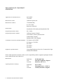
DECLARATION OF CONFORMITY
ADDENDUM
Application of Council Directive(s):
89/336/EEC
73/23/EEC
Manufacturer’s Name:
Cabletron Systems, Inc.
Manufacturer’s Address:
35 Industrial Way
P. O. Box 5005
Rochester, NH 03866
Product Name:
SmartSwitch 2500 family and SmartSwitch 6500
European Representative Name:
Mr. J. Solari
European Representative Address:
Cabletron Systems, Limited
Nexus House, Newbury Business Park
London Road, Newbury
Berkshire RG13 2PZ, England
Conformance to Directive(s)/Product Standards:
EC Directive 89/336/EEC
EC Directive 73/23/EEC
EN 55022
EN 50082-1
EN 60950
Equipment Type/Environment:
Networking Equipment, for use in a Commercial or Light
Industrial Environment.
We the undersigned, hereby declare, under our sole responsibility, that the equipment packaged with this
notice conforms to the above directives.
Manufacturer:
Full Name:
Title:
Location:
Mr. Ronald Fotino
Principal Compliance Engineer
Rochester, NH. U.S.A.
Legal Repersentative in Europe:
Full Name:
Title:
Location:
Mr. J. Solari
Managing Director - E.M.E.A.
Newbury, Berkshire, England
iv SmartSwitch ATM Switch Reference Manual
SAFETY INFORMATION
CLASS 1 LASER TRANSCEIVERS
The IOM-29-4, IOM-29-4-IR, IOM-29-4-LR, IOM-39-1 and IOM-39-1-LR connectors use Class 1 Laser transceivers.
Read the following safety information before installing or operating one of these modules.
The Class 1 Laser transceivers use an optical feedback loop to maintain Class 1 operation limits. This control loop
eliminates the need for maintenance checks or adjustments. The output is factory set, and does not allow any user
adjustment. Class 1 Laser transceivers comply with the following safety standards:
•
•
•
21 CFR 1040.10 and 1040.11 U. S. Department of Health and Human Services (FDA).
IEC Publication 825 (International Electrotechnical Commission).
CENELEC EN 60825 (European Committee for Electrotechnical Standardization).
When operating within their performance limitations, laser transceiver output meets the Class 1 accessible emission
limit of all three standards. Class 1 levels of laser radiation are not considered hazardous.
LASER RADIATION AND CONNECTORS
When the connector is in place, all laser radiation remains within the fiber. The maximum amount of radiant power
exiting the fiber (under normal conditions) is -12.6dBm or 55x10-6 watts.
Removing the optical connector from the transceiver allows laser radiation to emit directly from the optical port. The
maximum radiance from the optical port (under worst case conditions) is 0.8 W cm -2 or 8x10³ W m-2 sr-1.
Do not use optical instruments to view the laser output. The use of optical instruments to view laser output increases
eye hazard. When viewing the output optical port, you must remove power from the network adapter.
SmartSwitch ATM Switch Reference Manual v
FIBER OPTIC PROTECTIVE CAPS
Warning
.READ BEFORE REMOVING FIBER OPTIC PROTECTIVE CAPS.
Cable assemblies and MMF/SMF ports are shipped with protective caps to prevent contamination. To avoid
contamination, replace port caps on all fiber optic devices when not in use.
Cable assemblies and MMF/SMF ports that become contaminated may experience signal loss or difficulty inserting
and removing cable assemblies from MMF/SMF ports.
Contamination can be removed from cable assemblies by:
1.
Blowing surfaces with canned duster (Chemtronics p/n ES1270 or equivalent).
2.
Using a fiber port cleaning swab (Alcoa Fujikura LTS p/n ACT-01 or equivalent) saturated with
optical-grade isopropyl alcohol, gently wipe the end surface of ferrules first; then wipe down the
sides of both ferrules.
3.
Blow ferrule surfaces dry with canned duster.
Contamination can be removed from MMF/SMF ports by:
1.
Using the extension tube supplied with canned duster, blow into the optical port, being careful not
to allow the extension tube to touch the bottom of the optical port.
2.
Reconnect cable and check for proper mating. If problems remain, gently wipe out optical port with
a DRY fiber port cleaning swab and repeat step 1.
Warning
To avoid contamination, replace port caps on all fiber optic devices when not
in use.
vi SmartSwitch ATM Switch Reference Manual
REGULATORY COMPLIANCE SUMMARY
SAFETY
The SmartSwitch 2500 family and SmartSwitch 6500 meets the safety requirements of UL 1950, CSA C22.2 No. 950,
EN 60950, IEC 950, and 73/23/EEC.
EMC
The SmartSwitch 2500 family and SmartSwitch 6500 meets the EMC requirements of FCC Part 15, EN 55022, CSA
C108.8, VCCI V-3/93.01, EN 50082-1, and 89/336/EEC.
SmartSwitch ATM Switch Reference Manual vii
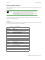
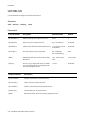
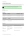
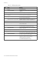
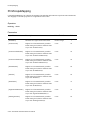
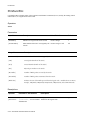
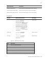
REVISION HISTORY
Document Name:
Document Part Number:
Document Order Number:
SmartSwitch ATM Switch Reference Manual
04-0054-01 Rev. A
9033003
Author: Robert de Peyster
Editor: Ayesha Maqsood
Illustrator: Mike Fornalski
Date
Revision
Description
"«Àˆ•Ê£™™™
04-0054-01 Rev. A
Initial release
viii SmartSwitch ATM Switch Reference Manual
Table of Contents
TABLE OF CONTENTS
1 Introduction . . . . . . . . . . . . . . . . . . . . . . . . . . . . . . . . . . . . . . . . . . . . . . . . . . . . . . . 1-1
Audience and Scope . . . . . . . . . . . . . . . . . . . . . . . . . . . . . . . . . . . . . . . . . . . . . . . . . . . . . . . . . . . . . . . 1-1
Definitions. . . . . . . . . . . . . . . . . . . . . . . . . . . . . . . . . . . . . . . . . . . . . . . . . . . . . . . . . . . . . . . . . . . . . . . 1-1
Content . . . . . . . . . . . . . . . . . . . . . . . . . . . . . . . . . . . . . . . . . . . . . . . . . . . . . . . . . . . . . . . . . . . . . . . . . 1-1
Additional Information . . . . . . . . . . . . . . . . . . . . . . . . . . . . . . . . . . . . . . . . . . . . . . . . . . . . . . . . . . . . . 1-2
Conventions. . . . . . . . . . . . . . . . . . . . . . . . . . . . . . . . . . . . . . . . . . . . . . . . . . . . . . . . . . . . . . . . . . . . . . 1-2
Abbreviations . . . . . . . . . . . . . . . . . . . . . . . . . . . . . . . . . . . . . . . . . . . . . . . . . . . . . . . . . . . . . . . . . . . . 1-3
Help Options . . . . . . . . . . . . . . . . . . . . . . . . . . . . . . . . . . . . . . . . . . . . . . . . . . . . . . . . . . . . . . . . . . . . . 1-4
Switch Attribute Entries . . . . . . . . . . . . . . . . . . . . . . . . . . . . . . . . . . . . . . . . . . . . . . . . . . . . . . . . . . . . 1-5
Port Numbering . . . . . . . . . . . . . . . . . . . . . . . . . . . . . . . . . . . . . . . . . . . . . . . . . . . . . . . . . . . . . . . . . . . 1-8
List of Operators and Switch Attributes . . . . . . . . . . . . . . . . . . . . . . . . . . . . . . . . . . . . . . . . . . . . . . . . 1-8
2 Console Commands . . . . . . . . . . . . . . . . . . . . . . . . . . . . . . . . . . . . . . . . . . . . . . . . 2-1
622LoopBack . . . . . . . . . . . . . . . . . . . . . . . . . . . . . . . . . . . . . . . . . . . . . . . . . . . . . . . . . . . . . . . . . . . . 2-1
AlarmDisplay . . . . . . . . . . . . . . . . . . . . . . . . . . . . . . . . . . . . . . . . . . . . . . . . . . . . . . . . . . . . . . . . . . . . 2-3
Alarms . . . . . . . . . . . . . . . . . . . . . . . . . . . . . . . . . . . . . . . . . . . . . . . . . . . . . . . . . . . . . . . . . . . . . . . . . . 2-4
Alias . . . . . . . . . . . . . . . . . . . . . . . . . . . . . . . . . . . . . . . . . . . . . . . . . . . . . . . . . . . . . . . . . . . . . . . . . . . 2-6
AtmFilter . . . . . . . . . . . . . . . . . . . . . . . . . . . . . . . . . . . . . . . . . . . . . . . . . . . . . . . . . . . . . . . . . . . . . . . . 2-9
AtmFilterSet . . . . . . . . . . . . . . . . . . . . . . . . . . . . . . . . . . . . . . . . . . . . . . . . . . . . . . . . . . . . . . . . . . . . 2-13
ATMRoute . . . . . . . . . . . . . . . . . . . . . . . . . . . . . . . . . . . . . . . . . . . . . . . . . . . . . . . . . . . . . . . . . . . . . 2-16
BUSClient . . . . . . . . . . . . . . . . . . . . . . . . . . . . . . . . . . . . . . . . . . . . . . . . . . . . . . . . . . . . . . . . . . . . . . 2-20
BUSErrorLog . . . . . . . . . . . . . . . . . . . . . . . . . . . . . . . . . . . . . . . . . . . . . . . . . . . . . . . . . . . . . . . . . . . 2-22
BUSELAN . . . . . . . . . . . . . . . . . . . . . . . . . . . . . . . . . . . . . . . . . . . . . . . . . . . . . . . . . . . . . . . . . . . . . 2-24
BUSLECStat . . . . . . . . . . . . . . . . . . . . . . . . . . . . . . . . . . . . . . . . . . . . . . . . . . . . . . . . . . . . . . . . . . . . 2-28
BUSStat. . . . . . . . . . . . . . . . . . . . . . . . . . . . . . . . . . . . . . . . . . . . . . . . . . . . . . . . . . . . . . . . . . . . . . . . 2-30
BUStype . . . . . . . . . . . . . . . . . . . . . . . . . . . . . . . . . . . . . . . . . . . . . . . . . . . . . . . . . . . . . . . . . . . . . . . 2-32
CACEqBwAllocScheme . . . . . . . . . . . . . . . . . . . . . . . . . . . . . . . . . . . . . . . . . . . . . . . . . . . . . . . . . . . 2-33
CacInfo . . . . . . . . . . . . . . . . . . . . . . . . . . . . . . . . . . . . . . . . . . . . . . . . . . . . . . . . . . . . . . . . . . . . . . . . 2-35
CACPortBw . . . . . . . . . . . . . . . . . . . . . . . . . . . . . . . . . . . . . . . . . . . . . . . . . . . . . . . . . . . . . . . . . . . . 2-37
CACServiceClassBw . . . . . . . . . . . . . . . . . . . . . . . . . . . . . . . . . . . . . . . . . . . . . . . . . . . . . . . . . . . . . 2-39
CACStatistics . . . . . . . . . . . . . . . . . . . . . . . . . . . . . . . . . . . . . . . . . . . . . . . . . . . . . . . . . . . . . . . . . . . 2-42
Client . . . . . . . . . . . . . . . . . . . . . . . . . . . . . . . . . . . . . . . . . . . . . . . . . . . . . . . . . . . . . . . . . . . . . . . . . . 2-44
ClientARP . . . . . . . . . . . . . . . . . . . . . . . . . . . . . . . . . . . . . . . . . . . . . . . . . . . . . . . . . . . . . . . . . . . . . . 2-48
ClientStat. . . . . . . . . . . . . . . . . . . . . . . . . . . . . . . . . . . . . . . . . . . . . . . . . . . . . . . . . . . . . . . . . . . . . . . 2-50
SmartSwitch ATM Switch Reference Manual ix
Table of Contents
ClientVC . . . . . . . . . . . . . . . . . . . . . . . . . . . . . . . . . . . . . . . . . . . . . . . . . . . . . . . . . . . . . . . . . . . . . . . 2-54
Community . . . . . . . . . . . . . . . . . . . . . . . . . . . . . . . . . . . . . . . . . . . . . . . . . . . . . . . . . . . . . . . . . . . . . 2-56
Config . . . . . . . . . . . . . . . . . . . . . . . . . . . . . . . . . . . . . . . . . . . . . . . . . . . . . . . . . . . . . . . . . . . . . . . . . 2-58
ConsoleTimeout. . . . . . . . . . . . . . . . . . . . . . . . . . . . . . . . . . . . . . . . . . . . . . . . . . . . . . . . . . . . . . . . . . 2-59
CoreDump . . . . . . . . . . . . . . . . . . . . . . . . . . . . . . . . . . . . . . . . . . . . . . . . . . . . . . . . . . . . . . . . . . . . . . 2-60
CpuSwitchover . . . . . . . . . . . . . . . . . . . . . . . . . . . . . . . . . . . . . . . . . . . . . . . . . . . . . . . . . . . . . . . . . . 2-62
CsmSwitchover . . . . . . . . . . . . . . . . . . . . . . . . . . . . . . . . . . . . . . . . . . . . . . . . . . . . . . . . . . . . . . . . . . 2-63
DS3E3LoopBack . . . . . . . . . . . . . . . . . . . . . . . . . . . . . . . . . . . . . . . . . . . . . . . . . . . . . . . . . . . . . . . . . 2-64
ELAN. . . . . . . . . . . . . . . . . . . . . . . . . . . . . . . . . . . . . . . . . . . . . . . . . . . . . . . . . . . . . . . . . . . . . . . . . . 2-66
ElanMcast . . . . . . . . . . . . . . . . . . . . . . . . . . . . . . . . . . . . . . . . . . . . . . . . . . . . . . . . . . . . . . . . . . . . . . 2-70
EventDisplay . . . . . . . . . . . . . . . . . . . . . . . . . . . . . . . . . . . . . . . . . . . . . . . . . . . . . . . . . . . . . . . . . . . . 2-71
Events . . . . . . . . . . . . . . . . . . . . . . . . . . . . . . . . . . . . . . . . . . . . . . . . . . . . . . . . . . . . . . . . . . . . . . . . . 2-72
Exit. . . . . . . . . . . . . . . . . . . . . . . . . . . . . . . . . . . . . . . . . . . . . . . . . . . . . . . . . . . . . . . . . . . . . . . . . . . . 2-74
Firmware . . . . . . . . . . . . . . . . . . . . . . . . . . . . . . . . . . . . . . . . . . . . . . . . . . . . . . . . . . . . . . . . . . . . . . . 2-75
History . . . . . . . . . . . . . . . . . . . . . . . . . . . . . . . . . . . . . . . . . . . . . . . . . . . . . . . . . . . . . . . . . . . . . . . . . 2-77
IlmiConfig . . . . . . . . . . . . . . . . . . . . . . . . . . . . . . . . . . . . . . . . . . . . . . . . . . . . . . . . . . . . . . . . . . . . . . 2-78
IPAddress. . . . . . . . . . . . . . . . . . . . . . . . . . . . . . . . . . . . . . . . . . . . . . . . . . . . . . . . . . . . . . . . . . . . . . . 2-81
IPATMARP . . . . . . . . . . . . . . . . . . . . . . . . . . . . . . . . . . . . . . . . . . . . . . . . . . . . . . . . . . . . . . . . . . . . . 2-82
IPATMClient . . . . . . . . . . . . . . . . . . . . . . . . . . . . . . . . . . . . . . . . . . . . . . . . . . . . . . . . . . . . . . . . . . . . 2-83
IPATMPVC . . . . . . . . . . . . . . . . . . . . . . . . . . . . . . . . . . . . . . . . . . . . . . . . . . . . . . . . . . . . . . . . . . . . . 2-86
IPATMStat. . . . . . . . . . . . . . . . . . . . . . . . . . . . . . . . . . . . . . . . . . . . . . . . . . . . . . . . . . . . . . . . . . . . . . 2-89
LANEClient. . . . . . . . . . . . . . . . . . . . . . . . . . . . . . . . . . . . . . . . . . . . . . . . . . . . . . . . . . . . . . . . . . . . . 2-91
LECMcast . . . . . . . . . . . . . . . . . . . . . . . . . . . . . . . . . . . . . . . . . . . . . . . . . . . . . . . . . . . . . . . . . . . . . . 2-93
LECS . . . . . . . . . . . . . . . . . . . . . . . . . . . . . . . . . . . . . . . . . . . . . . . . . . . . . . . . . . . . . . . . . . . . . . . . . . 2-95
LECSELAN. . . . . . . . . . . . . . . . . . . . . . . . . . . . . . . . . . . . . . . . . . . . . . . . . . . . . . . . . . . . . . . . . . . . . 2-96
LECSELANLEC . . . . . . . . . . . . . . . . . . . . . . . . . . . . . . . . . . . . . . . . . . . . . . . . . . . . . . . . . . . . . . . . . 2-99
LECSELANNameTable . . . . . . . . . . . . . . . . . . . . . . . . . . . . . . . . . . . . . . . . . . . . . . . . . . . . . . . . . . 2-102
LECSELANPolicy. . . . . . . . . . . . . . . . . . . . . . . . . . . . . . . . . . . . . . . . . . . . . . . . . . . . . . . . . . . . . . . 2-104
LECSErrorLog. . . . . . . . . . . . . . . . . . . . . . . . . . . . . . . . . . . . . . . . . . . . . . . . . . . . . . . . . . . . . . . . . . 2-107
LECSErrorLogControl . . . . . . . . . . . . . . . . . . . . . . . . . . . . . . . . . . . . . . . . . . . . . . . . . . . . . . . . . . . 2-109
LECSNeighbor . . . . . . . . . . . . . . . . . . . . . . . . . . . . . . . . . . . . . . . . . . . . . . . . . . . . . . . . . . . . . . . . . 2-111
LECSNeighborInfo . . . . . . . . . . . . . . . . . . . . . . . . . . . . . . . . . . . . . . . . . . . . . . . . . . . . . . . . . . . . . . 2-113
LECSServerList. . . . . . . . . . . . . . . . . . . . . . . . . . . . . . . . . . . . . . . . . . . . . . . . . . . . . . . . . . . . . . . . . 2-114
LECSPacketSizes . . . . . . . . . . . . . . . . . . . . . . . . . . . . . . . . . . . . . . . . . . . . . . . . . . . . . . . . . . . . . . . 2-116
LECSStat . . . . . . . . . . . . . . . . . . . . . . . . . . . . . . . . . . . . . . . . . . . . . . . . . . . . . . . . . . . . . . . . . . . . . . 2-118
LECSTLVParam . . . . . . . . . . . . . . . . . . . . . . . . . . . . . . . . . . . . . . . . . . . . . . . . . . . . . . . . . . . . . . . . 2-120
LECSTLVSet. . . . . . . . . . . . . . . . . . . . . . . . . . . . . . . . . . . . . . . . . . . . . . . . . . . . . . . . . . . . . . . . . . . 2-122
LECSVCC . . . . . . . . . . . . . . . . . . . . . . . . . . . . . . . . . . . . . . . . . . . . . . . . . . . . . . . . . . . . . . . . . . . . . 2-128
LES . . . . . . . . . . . . . . . . . . . . . . . . . . . . . . . . . . . . . . . . . . . . . . . . . . . . . . . . . . . . . . . . . . . . . . . . . . 2-129
x
SmartSwitch ATM Switch Reference Manual
Table of Contents
LESARP . . . . . . . . . . . . . . . . . . . . . . . . . . . . . . . . . . . . . . . . . . . . . . . . . . . . . . . . . . . . . . . . . . . . . . 2-130
LESClient . . . . . . . . . . . . . . . . . . . . . . . . . . . . . . . . . . . . . . . . . . . . . . . . . . . . . . . . . . . . . . . . . . . . . 2-131
LESELAN . . . . . . . . . . . . . . . . . . . . . . . . . . . . . . . . . . . . . . . . . . . . . . . . . . . . . . . . . . . . . . . . . . . . . 2-133
LESErrorLog . . . . . . . . . . . . . . . . . . . . . . . . . . . . . . . . . . . . . . . . . . . . . . . . . . . . . . . . . . . . . . . . . . . 2-137
LESLECStat . . . . . . . . . . . . . . . . . . . . . . . . . . . . . . . . . . . . . . . . . . . . . . . . . . . . . . . . . . . . . . . . . . . 2-140
LESLNNIInfo . . . . . . . . . . . . . . . . . . . . . . . . . . . . . . . . . . . . . . . . . . . . . . . . . . . . . . . . . . . . . . . . . . 2-142
LESLNNIStat . . . . . . . . . . . . . . . . . . . . . . . . . . . . . . . . . . . . . . . . . . . . . . . . . . . . . . . . . . . . . . . . . . 2-144
LESStat . . . . . . . . . . . . . . . . . . . . . . . . . . . . . . . . . . . . . . . . . . . . . . . . . . . . . . . . . . . . . . . . . . . . . . . 2-147
LinkMonitorTimeout. . . . . . . . . . . . . . . . . . . . . . . . . . . . . . . . . . . . . . . . . . . . . . . . . . . . . . . . . . . . . 2-150
LNNIInfo. . . . . . . . . . . . . . . . . . . . . . . . . . . . . . . . . . . . . . . . . . . . . . . . . . . . . . . . . . . . . . . . . . . . . . 2-151
LNNIStatus . . . . . . . . . . . . . . . . . . . . . . . . . . . . . . . . . . . . . . . . . . . . . . . . . . . . . . . . . . . . . . . . . . . . 2-153
McastClients . . . . . . . . . . . . . . . . . . . . . . . . . . . . . . . . . . . . . . . . . . . . . . . . . . . . . . . . . . . . . . . . . . . 2-155
MinMaxTableIndex. . . . . . . . . . . . . . . . . . . . . . . . . . . . . . . . . . . . . . . . . . . . . . . . . . . . . . . . . . . . . . 2-157
MyNMAddr. . . . . . . . . . . . . . . . . . . . . . . . . . . . . . . . . . . . . . . . . . . . . . . . . . . . . . . . . . . . . . . . . . . . 2-158
NetPrefix . . . . . . . . . . . . . . . . . . . . . . . . . . . . . . . . . . . . . . . . . . . . . . . . . . . . . . . . . . . . . . . . . . . . . . 2-159
NetworkClock . . . . . . . . . . . . . . . . . . . . . . . . . . . . . . . . . . . . . . . . . . . . . . . . . . . . . . . . . . . . . . . . . . 2-162
Passwd. . . . . . . . . . . . . . . . . . . . . . . . . . . . . . . . . . . . . . . . . . . . . . . . . . . . . . . . . . . . . . . . . . . . . . . . 2-163
Ping . . . . . . . . . . . . . . . . . . . . . . . . . . . . . . . . . . . . . . . . . . . . . . . . . . . . . . . . . . . . . . . . . . . . . . . . . . 2-164
PnniInterface . . . . . . . . . . . . . . . . . . . . . . . . . . . . . . . . . . . . . . . . . . . . . . . . . . . . . . . . . . . . . . . . . . . 2-165
PnniLink . . . . . . . . . . . . . . . . . . . . . . . . . . . . . . . . . . . . . . . . . . . . . . . . . . . . . . . . . . . . . . . . . . . . . . 2-168
PnniMetrics . . . . . . . . . . . . . . . . . . . . . . . . . . . . . . . . . . . . . . . . . . . . . . . . . . . . . . . . . . . . . . . . . . . . 2-171
PnniNeighbor . . . . . . . . . . . . . . . . . . . . . . . . . . . . . . . . . . . . . . . . . . . . . . . . . . . . . . . . . . . . . . . . . . 2-176
PnniNetworkLink . . . . . . . . . . . . . . . . . . . . . . . . . . . . . . . . . . . . . . . . . . . . . . . . . . . . . . . . . . . . . . . 2-179
PnniNetworkNode. . . . . . . . . . . . . . . . . . . . . . . . . . . . . . . . . . . . . . . . . . . . . . . . . . . . . . . . . . . . . . . 2-182
PnniNode. . . . . . . . . . . . . . . . . . . . . . . . . . . . . . . . . . . . . . . . . . . . . . . . . . . . . . . . . . . . . . . . . . . . . . 2-185
PnniNodeTimer . . . . . . . . . . . . . . . . . . . . . . . . . . . . . . . . . . . . . . . . . . . . . . . . . . . . . . . . . . . . . . . . . 2-188
PnniPeerGroupId . . . . . . . . . . . . . . . . . . . . . . . . . . . . . . . . . . . . . . . . . . . . . . . . . . . . . . . . . . . . . . . . 2-192
PnniPglElection. . . . . . . . . . . . . . . . . . . . . . . . . . . . . . . . . . . . . . . . . . . . . . . . . . . . . . . . . . . . . . . . . 2-193
PnniPtse. . . . . . . . . . . . . . . . . . . . . . . . . . . . . . . . . . . . . . . . . . . . . . . . . . . . . . . . . . . . . . . . . . . . . . . 2-196
PnniReachableAddress . . . . . . . . . . . . . . . . . . . . . . . . . . . . . . . . . . . . . . . . . . . . . . . . . . . . . . . . . . . 2-198
PnniScopeMapping . . . . . . . . . . . . . . . . . . . . . . . . . . . . . . . . . . . . . . . . . . . . . . . . . . . . . . . . . . . . . . 2-200
PnniStats . . . . . . . . . . . . . . . . . . . . . . . . . . . . . . . . . . . . . . . . . . . . . . . . . . . . . . . . . . . . . . . . . . . . . . 2-205
PnniSummaryAddress. . . . . . . . . . . . . . . . . . . . . . . . . . . . . . . . . . . . . . . . . . . . . . . . . . . . . . . . . . . . 2-207
PnniSvccRcc . . . . . . . . . . . . . . . . . . . . . . . . . . . . . . . . . . . . . . . . . . . . . . . . . . . . . . . . . . . . . . . . . . . 2-210
PnniTnsRoute . . . . . . . . . . . . . . . . . . . . . . . . . . . . . . . . . . . . . . . . . . . . . . . . . . . . . . . . . . . . . . . . . . 2-212
Port . . . . . . . . . . . . . . . . . . . . . . . . . . . . . . . . . . . . . . . . . . . . . . . . . . . . . . . . . . . . . . . . . . . . . . . . . . 2-216
PortClockMode . . . . . . . . . . . . . . . . . . . . . . . . . . . . . . . . . . . . . . . . . . . . . . . . . . . . . . . . . . . . . . . . . 2-219
PortConfig . . . . . . . . . . . . . . . . . . . . . . . . . . . . . . . . . . . . . . . . . . . . . . . . . . . . . . . . . . . . . . . . . . . . . 2-221
PortFilterSet . . . . . . . . . . . . . . . . . . . . . . . . . . . . . . . . . . . . . . . . . . . . . . . . . . . . . . . . . . . . . . . . . . . 2-225
SmartSwitch ATM Switch Reference Manual xi
Table of Contents
PortMode . . . . . . . . . . . . . . . . . . . . . . . . . . . . . . . . . . . . . . . . . . . . . . . . . . . . . . . . . . . . . . . . . . . . . . 2-227
PortStat . . . . . . . . . . . . . . . . . . . . . . . . . . . . . . . . . . . . . . . . . . . . . . . . . . . . . . . . . . . . . . . . . . . . . . . 2-231
PortTrafficCongestion . . . . . . . . . . . . . . . . . . . . . . . . . . . . . . . . . . . . . . . . . . . . . . . . . . . . . . . . . . . . 2-235
Privilege. . . . . . . . . . . . . . . . . . . . . . . . . . . . . . . . . . . . . . . . . . . . . . . . . . . . . . . . . . . . . . . . . . . . . . . 2-238
Prompt . . . . . . . . . . . . . . . . . . . . . . . . . . . . . . . . . . . . . . . . . . . . . . . . . . . . . . . . . . . . . . . . . . . . . . . . 2-239
PVC . . . . . . . . . . . . . . . . . . . . . . . . . . . . . . . . . . . . . . . . . . . . . . . . . . . . . . . . . . . . . . . . . . . . . . . . . . 2-240
PVCById . . . . . . . . . . . . . . . . . . . . . . . . . . . . . . . . . . . . . . . . . . . . . . . . . . . . . . . . . . . . . . . . . . . . . . 2-248
PVP . . . . . . . . . . . . . . . . . . . . . . . . . . . . . . . . . . . . . . . . . . . . . . . . . . . . . . . . . . . . . . . . . . . . . . . . . . 2-250
PVPById . . . . . . . . . . . . . . . . . . . . . . . . . . . . . . . . . . . . . . . . . . . . . . . . . . . . . . . . . . . . . . . . . . . . . . 2-256
Reboot . . . . . . . . . . . . . . . . . . . . . . . . . . . . . . . . . . . . . . . . . . . . . . . . . . . . . . . . . . . . . . . . . . . . . . . . 2-258
RedundancyConfigBackup . . . . . . . . . . . . . . . . . . . . . . . . . . . . . . . . . . . . . . . . . . . . . . . . . . . . . . . . 2-259
RedundancyInfo. . . . . . . . . . . . . . . . . . . . . . . . . . . . . . . . . . . . . . . . . . . . . . . . . . . . . . . . . . . . . . . . . 2-260
RedundancyOn . . . . . . . . . . . . . . . . . . . . . . . . . . . . . . . . . . . . . . . . . . . . . . . . . . . . . . . . . . . . . . . . . 2-262
RedundancyOff . . . . . . . . . . . . . . . . . . . . . . . . . . . . . . . . . . . . . . . . . . . . . . . . . . . . . . . . . . . . . . . . . 2-263
RedundancyStatus . . . . . . . . . . . . . . . . . . . . . . . . . . . . . . . . . . . . . . . . . . . . . . . . . . . . . . . . . . . . . . . 2-264
Route . . . . . . . . . . . . . . . . . . . . . . . . . . . . . . . . . . . . . . . . . . . . . . . . . . . . . . . . . . . . . . . . . . . . . . . . . 2-266
Rows . . . . . . . . . . . . . . . . . . . . . . . . . . . . . . . . . . . . . . . . . . . . . . . . . . . . . . . . . . . . . . . . . . . . . . . . . 2-268
SARStat . . . . . . . . . . . . . . . . . . . . . . . . . . . . . . . . . . . . . . . . . . . . . . . . . . . . . . . . . . . . . . . . . . . . . . . 2-269
ServiceRegistry . . . . . . . . . . . . . . . . . . . . . . . . . . . . . . . . . . . . . . . . . . . . . . . . . . . . . . . . . . . . . . . . . 2-272
Shutdown . . . . . . . . . . . . . . . . . . . . . . . . . . . . . . . . . . . . . . . . . . . . . . . . . . . . . . . . . . . . . . . . . . . . . . 2-275
SigStatistics . . . . . . . . . . . . . . . . . . . . . . . . . . . . . . . . . . . . . . . . . . . . . . . . . . . . . . . . . . . . . . . . . . . . 2-276
SigTimer . . . . . . . . . . . . . . . . . . . . . . . . . . . . . . . . . . . . . . . . . . . . . . . . . . . . . . . . . . . . . . . . . . . . . . 2-279
SlotConfig . . . . . . . . . . . . . . . . . . . . . . . . . . . . . . . . . . . . . . . . . . . . . . . . . . . . . . . . . . . . . . . . . . . . . 2-281
Spvc . . . . . . . . . . . . . . . . . . . . . . . . . . . . . . . . . . . . . . . . . . . . . . . . . . . . . . . . . . . . . . . . . . . . . . . . . . 2-283
SpvcAddress . . . . . . . . . . . . . . . . . . . . . . . . . . . . . . . . . . . . . . . . . . . . . . . . . . . . . . . . . . . . . . . . . . . 2-290
SpvcBase . . . . . . . . . . . . . . . . . . . . . . . . . . . . . . . . . . . . . . . . . . . . . . . . . . . . . . . . . . . . . . . . . . . . . . 2-292
SpvcCallFailuresTrapEnable . . . . . . . . . . . . . . . . . . . . . . . . . . . . . . . . . . . . . . . . . . . . . . . . . . . . . . . 2-294
SpvcFailed . . . . . . . . . . . . . . . . . . . . . . . . . . . . . . . . . . . . . . . . . . . . . . . . . . . . . . . . . . . . . . . . . . . . . 2-295
SpvcNotifyInterval . . . . . . . . . . . . . . . . . . . . . . . . . . . . . . . . . . . . . . . . . . . . . . . . . . . . . . . . . . . . . . 2-297
SpvcRestart . . . . . . . . . . . . . . . . . . . . . . . . . . . . . . . . . . . . . . . . . . . . . . . . . . . . . . . . . . . . . . . . . . . . 2-298
SpvcTarget. . . . . . . . . . . . . . . . . . . . . . . . . . . . . . . . . . . . . . . . . . . . . . . . . . . . . . . . . . . . . . . . . . . . . 2-299
Spvp . . . . . . . . . . . . . . . . . . . . . . . . . . . . . . . . . . . . . . . . . . . . . . . . . . . . . . . . . . . . . . . . . . . . . . . . . . 2-301
SpvpFailed . . . . . . . . . . . . . . . . . . . . . . . . . . . . . . . . . . . . . . . . . . . . . . . . . . . . . . . . . . . . . . . . . . . . . 2-307
SpvpRestart . . . . . . . . . . . . . . . . . . . . . . . . . . . . . . . . . . . . . . . . . . . . . . . . . . . . . . . . . . . . . . . . . . . . 2-309
SpvpTarget. . . . . . . . . . . . . . . . . . . . . . . . . . . . . . . . . . . . . . . . . . . . . . . . . . . . . . . . . . . . . . . . . . . . . 2-311
SSCOPConfig . . . . . . . . . . . . . . . . . . . . . . . . . . . . . . . . . . . . . . . . . . . . . . . . . . . . . . . . . . . . . . . . . . 2-313
SSCOPStatistics. . . . . . . . . . . . . . . . . . . . . . . . . . . . . . . . . . . . . . . . . . . . . . . . . . . . . . . . . . . . . . . . . 2-316
SVC . . . . . . . . . . . . . . . . . . . . . . . . . . . . . . . . . . . . . . . . . . . . . . . . . . . . . . . . . . . . . . . . . . . . . . . . . . 2-320
SVCById . . . . . . . . . . . . . . . . . . . . . . . . . . . . . . . . . . . . . . . . . . . . . . . . . . . . . . . . . . . . . . . . . . . . . . 2-322
xii
SmartSwitch ATM Switch Reference Manual
Table of Contents
Switch . . . . . . . . . . . . . . . . . . . . . . . . . . . . . . . . . . . . . . . . . . . . . . . . . . . . . . . . . . . . . . . . . . . . . . . . 2-325
SwitchConfig. . . . . . . . . . . . . . . . . . . . . . . . . . . . . . . . . . . . . . . . . . . . . . . . . . . . . . . . . . . . . . . . . . . 2-327
SwitchName . . . . . . . . . . . . . . . . . . . . . . . . . . . . . . . . . . . . . . . . . . . . . . . . . . . . . . . . . . . . . . . . . . . 2-330
SwitchTrafficCongestion . . . . . . . . . . . . . . . . . . . . . . . . . . . . . . . . . . . . . . . . . . . . . . . . . . . . . . . . . 2-331
TrafficDescriptor . . . . . . . . . . . . . . . . . . . . . . . . . . . . . . . . . . . . . . . . . . . . . . . . . . . . . . . . . . . . . . . . 2-333
TrapCommunity . . . . . . . . . . . . . . . . . . . . . . . . . . . . . . . . . . . . . . . . . . . . . . . . . . . . . . . . . . . . . . . . 2-337
TrustedNMS . . . . . . . . . . . . . . . . . . . . . . . . . . . . . . . . . . . . . . . . . . . . . . . . . . . . . . . . . . . . . . . . . . . 2-339
3 Boot Load Commands . . . . . . . . . . . . . . . . . . . . . . . . . . . . . . . . . . . . . . . . . . . . . . 3-1
Accessing the Boot Load Commands . . . . . . . . . . . . . . . . . . . . . . . . . . . . . . . . . . . . . . . . . . . . . . . . . . 3-1
chpi Command . . . . . . . . . . . . . . . . . . . . . . . . . . . . . . . . . . . . . . . . . . . . . . . . . . . . . . . . . . . . . . . . . . . 3-2
clfs Command . . . . . . . . . . . . . . . . . . . . . . . . . . . . . . . . . . . . . . . . . . . . . . . . . . . . . . . . . . . . . . . . . . . . 3-2
dcfg Command . . . . . . . . . . . . . . . . . . . . . . . . . . . . . . . . . . . . . . . . . . . . . . . . . . . . . . . . . . . . . . . . . . . 3-3
df Command . . . . . . . . . . . . . . . . . . . . . . . . . . . . . . . . . . . . . . . . . . . . . . . . . . . . . . . . . . . . . . . . . . . . . 3-3
go Command . . . . . . . . . . . . . . . . . . . . . . . . . . . . . . . . . . . . . . . . . . . . . . . . . . . . . . . . . . . . . . . . . . . . . 3-4
he Command . . . . . . . . . . . . . . . . . . . . . . . . . . . . . . . . . . . . . . . . . . . . . . . . . . . . . . . . . . . . . . . . . . . . . 3-5
ponf Command . . . . . . . . . . . . . . . . . . . . . . . . . . . . . . . . . . . . . . . . . . . . . . . . . . . . . . . . . . . . . . . . . . . 3-6
scsm Command . . . . . . . . . . . . . . . . . . . . . . . . . . . . . . . . . . . . . . . . . . . . . . . . . . . . . . . . . . . . . . . . . . . 3-6
swms Command . . . . . . . . . . . . . . . . . . . . . . . . . . . . . . . . . . . . . . . . . . . . . . . . . . . . . . . . . . . . . . . . . . 3-7
A Acronyms . . . . . . . . . . . . . . . . . . . . . . . . . . . . . . . . . . . . . . . . . . . . . . . . . . . . . . . . A-1
B Event/Alarm Messages . . . . . . . . . . . . . . . . . . . . . . . . . . . . . . . . . . . . . . . . . . . . . . B-1
C Technical Support . . . . . . . . . . . . . . . . . . . . . . . . . . . . . . . . . . . . . . . . . . . . . . . . . . C-1
Telephone Assistance . . . . . . . . . . . . . . . . . . . . . . . . . . . . . . . . . . . . . . . . . . . . . . . . . . . . . . . . . . . . . .C-1
FAX Service . . . . . . . . . . . . . . . . . . . . . . . . . . . . . . . . . . . . . . . . . . . . . . . . . . . . . . . . . . . . . . . . . . . . .C-1
Electronic Services . . . . . . . . . . . . . . . . . . . . . . . . . . . . . . . . . . . . . . . . . . . . . . . . . . . . . . . . . . . . . . . .C-1
Placing A Support Call . . . . . . . . . . . . . . . . . . . . . . . . . . . . . . . . . . . . . . . . . . . . . . . . . . . . . . . . . . . . .C-1
Hardware Warranty . . . . . . . . . . . . . . . . . . . . . . . . . . . . . . . . . . . . . . . . . . . . . . . . . . . . . . . . . . . . . . . .C-2
Software Warranty . . . . . . . . . . . . . . . . . . . . . . . . . . . . . . . . . . . . . . . . . . . . . . . . . . . . . . . . . . . . . . . .C-2
Repair Services . . . . . . . . . . . . . . . . . . . . . . . . . . . . . . . . . . . . . . . . . . . . . . . . . . . . . . . . . . . . . . . . . . .C-2
Index . . . . . . . . . . . . . . . . . . . . . . . . . . . . . . . . . . . . . . . . . . . . . . . . . . . . . . . . . . . . .I-1
SmartSwitch ATM Switch Reference Manual xiii
List of Tables
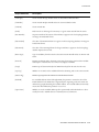
LIST OF TABLES
Table 1-1
List of Operators . . . . . . . . . . . . . . . . . . . . . . . . . . . . . . . . . . . . . . . . . . . . . . . . . . . . . . . . . . . . . . . . . . 1-5
Table 2-1
OC-12/STM-4 Port Loopback Modes . . . . . . . . . . . . . . . . . . . . . . . . . . . . . . . . . . . . . . . . . . . . . . . . . . 2-2
Table 2-2
BUSErrorLog Error Codes . . . . . . . . . . . . . . . . . . . . . . . . . . . . . . . . . . . . . . . . . . . . . . . . . . . . . . . . . 2-23
Table 2-3
DS3 and E3 Loopback Modes . . . . . . . . . . . . . . . . . . . . . . . . . . . . . . . . . . . . . . . . . . . . . . . . . . . . . . . 2-65
Table 2-4
ELAN Assignment Policies. . . . . . . . . . . . . . . . . . . . . . . . . . . . . . . . . . . . . . . . . . . . . . . . . . . . . . . . 2-105
Table 2-5
LECSErrorLog Error Codes . . . . . . . . . . . . . . . . . . . . . . . . . . . . . . . . . . . . . . . . . . . . . . . . . . . . . . . 2-107
Table 2-6
LECSErrorLog Status . . . . . . . . . . . . . . . . . . . . . . . . . . . . . . . . . . . . . . . . . . . . . . . . . . . . . . . . . . . . 2-110
Table 2-7
LESErrorLog Error Codes. . . . . . . . . . . . . . . . . . . . . . . . . . . . . . . . . . . . . . . . . . . . . . . . . . . . . . . . . 2-138
Table 2-8
Port Clock Modes . . . . . . . . . . . . . . . . . . . . . . . . . . . . . . . . . . . . . . . . . . . . . . . . . . . . . . . . . . . . . . . 2-220
Table 2-9
I/O Module ID Numbers . . . . . . . . . . . . . . . . . . . . . . . . . . . . . . . . . . . . . . . . . . . . . . . . . . . . . . . . . . 2-229
Table 2-10
SPVC Failure Cause Codes . . . . . . . . . . . . . . . . . . . . . . . . . . . . . . . . . . . . . . . . . . . . . . . . . . . . . . . . 2-286
Table 2-11
SPVP Failure Cause Codes . . . . . . . . . . . . . . . . . . . . . . . . . . . . . . . . . . . . . . . . . . . . . . . . . . . . . . . . 2-303
Table B-1
Event and Alarm Commands. . . . . . . . . . . . . . . . . . . . . . . . . . . . . . . . . . . . . . . . . . . . . . . . . . . . . . . . B-1
Table B-2
Event Severity . . . . . . . . . . . . . . . . . . . . . . . . . . . . . . . . . . . . . . . . . . . . . . . . . . . . . . . . . . . . . . . . . . . B-2
Table B-3
Event ID Prefixes. . . . . . . . . . . . . . . . . . . . . . . . . . . . . . . . . . . . . . . . . . . . . . . . . . . . . . . . . . . . . . . . . B-3
xiv
SmartSwitch ATM Switch Reference Manual
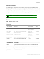
1 INTRODUCTION
This reference manual describes the console commands for the SmartSwitch 2500 family and the SmartSwitch 6500.
Unless otherwise noted, the information in this manual applies to both the SmartSwitch 2500 family and SmartSwitch
6500.
Audience and Scope
The manual is intended for network administrators and others responsible for maintaining the SmartSwitch 2500
family and the SmartSwitch 6500.
Definitions
The manual is organized alphabetically by switch attribute.
•
The definition of a switch attribute is a function that manipulates the switch in a specific way. For
example: buselan
•
The definition of an operator is the active verb that makes the switch attribute perform a specific
task. For example: show
•
The definition of a command is the combination of an operator plus a switch attribute. For example:
show buselan
Note
Asmall group of attributes does not require operators and can function as
standalone commands. Those attributes are: exit, history, passwd, reboot and
shutdown.
Content
•
Chapter 2, "Console Commands," gives definitions, descriptions, and examples of all available
commands for the SmartSwitch 2500 family and SmartSwitch 6500.
•
Chapter 3, “Boot Load Commands” gives definitions, descriptions, and examples of the low-level
boot load commands.
•
Appendix A, “Acronyms,” spells out the ATM acronyms used in this manual as well as those found
in SmartSwitch user guides.
•
Appendix B, “Event/Alarm Messages,” describes the format of event and alarm messages that are
recorded to circular buffers and can be displayed on the console.
•
Appendix C, “Technical Support,” gives instructions for contacting Cabletron by telephone, fax,
electronic mail, and the World Wide Web.
SmartSwitch ATM Switch Reference Manual 1-1
Additional Information
Introduction
Additional Information
You will find a list of acronyms, details about technical support, and an index at the back of this manual. The index
contains page references for all switch attribute sections, command parameters, operators, command descriptions and
command examples. There is also a table of commands at the end of this chapter. It lists all switch attributes by their
operators.
For details on how to use the SmartSwitch 2500 family or SmartSwitch 6500, see the SmartSwitch user guide that
applies. Each SmartSwitch user guide contains task-oriented information on switch configuration, maintenance, and
SNMP (simple network management protocol). Each also contains an overview of switch capabilities.
Conventions
This manual uses the following conventions for instructions and information:
•
Information you enter (console commands and input parameters) is shown in bold
and requires a space between the operator and switch attribute.
•
•
•
Input and output parameters are shown in [Square Brackets].
Courier 8
font
Input definitions are shown in <anglebrackets>, as joined text and not case sensitive.
Filter flags </s> (summary) or </d> (detail) are available with certain show commands and apply
to different information viewing levels. Filter flags require a space between them and the full
command. The/s option is the same as the standard default option; the /d option provides additiional
details. For example:
switch_prompt # show client /s
ClientNumber(ALL)
:
Client Type
IP Address
Server Type Server Conn Status
==============================================================================
1 LANE
90.1.1.186
LECS
Established Operational
3 IP/ATM 90.1.1.124
Local
Established Operational
switch_prompt #
switch_prompt # show client /d
ClientNumber(ALL)
:
LANE Client 1
==============================================================================
Client State
: Operational
Client Address
: 39:00:00:00:00:00:00:00:00:00:14:15:00:00:20:D4:14:15:00:00
LAN Name
: elan1
LECS Addr Source : ILMI
LECS Address
: 39:00:00:00:00:00:00:00:00:00:14:15:00:00:20:D4:14:15:00:01
LES Address
: 39:00:00:00:00:00:00:00:00:00:14:15:00:00:20:D4:14:15:00:02
LAN Type
: 802.3
MTU
: 1516
IP Address
: 90.1.1.186
IP NetMask
: 255.255.255.0
IP/ATM Client 3
==============================================================================
Client State
: Operational
Client Address
: 39:00:00:00:00:00:00:00:00:00:14:15:00:00:00:5A:01:01:7C:00
Server
: is local
Server Connection : Established
MTU
: 9180
IP Address
: 90.1.1.124
1-2 SmartSwitch ATM Switch Reference Manual
Introduction
Abbreviations
Abbreviations
Pay attention to how switch attributes appear in section headings of Chapter 2. Switch attributes are not case sensitive,
but you must spell them correctly. For example, if the heading states BUSStat, you must enter busstat and not
busstats.
switch_prompt # show busstats
Command busstats not Valid for Action show
Type Help <command> for help
switch_prompt #
switch_prompt # show busstat
ELANNumber(ALL)
:
BUS ELANs
============================================================================
ELAN ELAN000 Statistics
Out Octets
: 0
Out Unicast
: 0
switch_prompt #
You can, however, abbreviate the switch attribute to the extent it is unique. For example, instead of entering show
porttrafficcongestion, you can just enter show portt. You can do the same with operators. For example, instead
of entering modify, you can enter mod. You should enter at least three characters for any operator. For example:
switch_prompt # modify portmode
PortNumber(ALL)
PortMode(SONET)
switch_prompt #
:
:
switch_prompt # mod portm
PortNumber(ALL)
PortMode(SONET)
switch_prompt #
:
:
If you enter part of a command, and that part is not unique, the console displays a numbered list of possible matching
commands. For example, entering show pnnin is ambiguous because there are several commands that start with
“pnnin.” In response, the console displays a list of possible commands:
switch_prompt # show pnnin
Objects beginning with pnnin for action show
0
:
PnniNeighbor
1
:
PnniNetworkLink
2
:
PnniNetworkNode
3
:
PnniNode
4
:
PnniNodeTimer
(#)Command (Q)uit? :
SmartSwitch ATM Switch Reference Manual 1-3
Help Options
Introduction
Help Options
The console provides several levels of help for console commands. For example, to list the switch attributes that can
be used with a particular operator, enter the word help (or ?) followed by the operator.
switch_prompt # help add
HELP ---add
==============================================================================
add
[ Alias | ATMRoute | BUSELAN | Community | ELAN | Interface |
IPATMClient | IPATMPVC | LANEClient | LECSELAN | LECSELANLEC |
LECSTLVSET | LESELAN | NetPrefix | PnniMetrics |
PnniSummaryAddress | PVC | Route | ServiceRegistry |
TrafficDescriptor | TrapCommunity ]
To get an explanation of a command and its parameters, enter the word help (or ?) before the command.
switch_prompt # ? add laneclient
Create LANE Client
==============================================================================
ClientNumber
Local Client Number (0-127)
LanName
Name of the ELAN to join
ServerType
Type of LANE Server [LECS, LES]
ServerAddress
ATM Address of the LANE Server
IPAddress
IP Address of the Client
NetMask
IP Netmask of the Client
MTU
MTU for the Client [1516, 9234, NONE]
While entering a command, you can get help about an input parameter. To do so, enter a question mark (?) at the
parameter prompt.
switch_prompt # add atmroute
PortNumber(A1)
: 1a3
AtmAddress()
: 39:00:00:00:00:00:00:00:00:00:14:72:80
PrefixLength(104)
:
Index(0)
:
Type(Internal)
: ?
The type of reachability. Use Internal, Exterior, or Reject.
Type(Internal)
: exterior
Scope(0)
:
MetricsTag(0)
:
Switch 4 #
Note
Press the Esc key to back out of any command before you enter the last value.
1-4 SmartSwitch ATM Switch Reference Manual
Introduction
Switch Attribute Entries
Switch Attribute Entries
Each switch attribute has an entry in Chapter 2. The entry starts with the attribute name and a brief explanation of the
attribute’s purpose.
Note
A few switch attributes apply to the SmartSwitch 6500 only. Those attributes are
indicated in Chapter 2 by the following notation after attribute name:
(SmartSwitch 6500 Only). If that notation does not appear, the attribute applies
both to the SmartSwitch 2500 family and to the SmartSwitch 6500.
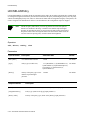
After the attribute name and explanation, each attribute entry in Chapter 2 has the following sections: Operators,
Parameters, Descriptions, and Examples.
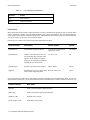
Operators
If an attribute requires operators, they are listed under an “Operators” heading. Following is a list of all possible switch
operators. If an operator has an alias, it is shown in parenthesis.
Table 1-1
List of Operators
Operator
Action
add (create)
Adds new object
activate
Activates an existing but deactivated object
backup
Backs up switch configuration
clear
Clears (initializes to 0) properties of an object
disable
Lowers privilege level
deactivate
Deactivates an existing object
delete (remove)
Deletes existing object
enable
Raises privilege level
flush
Flushes all entries
modify (set)
Sets properties of an existing object
restart
Restarts LANE clients
restore
Restores switch configuration
setup
Sets up switch
show (display)
Shows properties of an object
start
Starts an object
SmartSwitch ATM Switch Reference Manual 1-5
Switch Attribute Entries
Introduction
Table 1-1
List of Operators (Continued)
Operator
Action
stop
Stops an object
update
Upgrades firmware
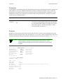
Parameters
Most switch attributes have input or output parameters (or both). If an attribute has parameters, they are listed in tables
under a “Parameters” heading. You enter input parameters at the console command line. You view output parameters
at the console screen after the command executes. Some input parameters have default values (shown in parenthesis).
You do not need to type an entry if you accept the default.
Following is an example of the format of input and output parameter tables.
Input Parameter
Description
Value/Field Size
Default
[ATMAddress]
ATM address assigned to the port.
13-20 byte hex-based format
separated by colons.
No default
[ClientNumber]
Number of the client. Each client on
the switch must have a unique client
number. Client numbers are shared
between LAN emulation (LANE) and
IP/ATM (IP over ATM) clients.
0 to 127, or All
All
[InterfaceType]
Interface type advertised by the port.
Private, Public
Private
[SigRole]
Signaling role of the port. Other is used Network, Other, User
only for autoConfig and pnni10.
Other
In the output parameter table below, </d> indicates parameters available only in detailed display mode. To view the
display for these parameters, type /d after the attribute in the command string (for example: operator attribute /d).
Output Parameter
Description
[Port ID]
Same as the [PortNumber] input parameter.
[Intf Type]
Same as the [InterfaceType] input parameter.
[Sig Role] </d>
Signaling role of the port.
[Client Address] </d>
ATM address of the client.
1-6 SmartSwitch ATM Switch Reference Manual
Introduction
Switch Attribute Entries
Descriptions
A “Descriptions” section follows parameters. The descriptions section shows command syntax (operator, attribute, and
input parameters). It also gives additional information on what the command does and how to use it. Finally, the
descriptions section indicates the privilege level required to use the command (Read Only, Administrator, or All).
Administrator privilege level is necessary for actions other than viewing output displays. All means any user has
complete access to command features.
Operator
Parameters/Permissions
Description
show
clientvc
[ClientNumber] <clientnumber>
Displays client ARP mapping details. In addition, it displays
VC details for local IP/ATM or LANE clients. For IP/ATM,
the associated IP address appears; for LANE, the associated
MAC address appears. (The associated address is what is
located at the other end of the VC.)
All
Examples
Examples are copied exactly from the switch console. They show how you enter console commands at the switch
prompt (for example: modify buselan). The other bold text (1, 103, pvc, 802.5, 4544) is input parameter values. Text
in brackets immediately following each parameter field indicates the current default (for example: ELANType(802.3)).
Note
With the exception of port numbering (1a1, 2b2.3, and so forth), most of the
console displays are identical for both the SmartSwitch 2500 family and the
SmartSwitch 6500. If the displays are not identical, the differences are noted in the
examples.
switch_prompt # modify buselan
ELANNumber(0)
:103
ELANName(ELAN102)
:elan103
ConnectMethod(SVC)
:pvc
ELANType(802.3)
:802.5
Multipoint(YES)
:
MTU(1516)
:4544
switch_prompt #
(console command)
(input entry)
(input entry)
(input entry)
(input entry)
(accept default)
(input entry)
switch_prompt # show buselan
ELANNumber : 103
ELAN : elan103
ELAN Number
:
ELAN Name
:
ATM Address
:
Max Frame Size
:
Connection Method :
Distribute VPI/VCI:
LAN Type
:
Multipoint
:
103
elan103
39:00:00:00:00:00:00:00:20:D4:14:15:00:00:20:D4:14:15:66:02
4544
PVC
0/50
802.5
YES
SmartSwitch ATM Switch Reference Manual 1-7
Port Numbering
Introduction
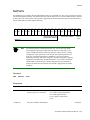
Port Numbering
Port numbering for the SmartSwitch 6500 is different from that for the SmartSwitch 2500 family. For the SmartSwitch
6500, physical port numbering uses the following format:
slot number
I/O module letter
port number
For example, port 3 of I/O module A on the TSM in slot 5 is represented by: 5a3
For the SmartSwitch 2500 family, physical port numbering does not use slot numbers. Physical port numbering for
the SmartSwitch 2500 family uses the following format:
I/O module letter
port number
For example, port 3 of module A is represented by: a3
Both the SmartSwitch 2500 family and SmartSwitch 6500 support virtual ports. Virtual ports are designated by a
period followed by the virtual port number (which both are appended to the physical port number). For example, for
the SmartSwitch 6500, virtual port 2 on physical port 7b1 is represented as: 7b1.3
For the SmartSwitch 2500 family, virtual port 2 on physical port c3 is represented as: c3.2
List of Operators and Switch Attributes
Following is a list of switch attributes used with operators. If an operator has an alias, it is shown in parenthesis.
Note
A small group of attributes does not require operators and can function as
standalone commands. Those attributes are: exit, history, passwd, reboot and
shutdown. In addition, several attributes apply to the SmartSwitch 6500 only. In
the following lists, attributes that apply to the SmartSwitch 6500 only are
indicated by an asterisk (*).
add (create)
Alias
AtmFilter
AtmFilterSet
ATMRoute
BUSELAN
Community
ELAN
IPATMClient
IPATMPVC
LANEClient
LECSELAN
LECSELANLEC
LECSELANNameTable
LECSELANPolicy
LECSNeighbor
LECSELANPacketSizes
LECSTLVSET
LESELAN
NetPrefix
PnniMetrics
PnniNode
PnniSummaryAddress
PnniTnsRoute
Port
PortFilterSet
PVC
PVP*
Route
1-8 SmartSwitch ATM Switch Reference Manual
Introduction
List of Operators and Switch Attributes
ServiceRegistry
Spvc
TrafficDescriptor
TrapCommunity
SpvcAddress
Spvp*
delete (remove)
Alarms
Alias
AtmFilter
AtmFilterSet
ATMRoute
BUSClient
BUSELAN
Client
Community
ELAN
Events
IPATMPVC
LECSELAN
LECSELANLEC
LECSELANNameTable
LECSELANPolicy
LECSErrorLog
LECSNeighbor
LECSPacketSizes
LECSTLVPARAM
LECSTLVSET
LESClient
LESELAN
NetPrefix
PnniMetrics
PnniNode
PnniSummaryAddress
PnniTnsRoute
Port
PortFilterSet
PVC
PVCById
PVP*
PVPById*
Route
ServiceRegistry
Spvc
SpvcAddress
Spvp*
TrafficDescriptor
TrapCommunity
modify (set)
622LoopBack
AlarmDisplay
Alias
AtmFilter
AtmFilterSet
BUSELAN
BUSType
CACEqBwAllocScheme
CACServiceClassBw
ConsoleTimeout
CoreDump
DS3E3LoopBack
EventDisplay
IlmiConfig
IpAddress
IPATMClient
LANEClient
LECSELAN
LECSELANLEC
LECSELANPolicy
LECSErrorLogControl
LECSTLVSet
LESELAN
LNNIInfo
LNNIStatus
MyNmAddr
NetworkClock
PnniInterface
SmartSwitch ATM Switch Reference Manual 1-9
List of Operators and Switch Attributes
Introduction
PnniNode
PnniNodeTimer
PnniPeerGroupId
PnniPglElection
PnniScopeMapping
PortClockMode
PortConfig
PortFilterSet
PortMode
PortTrafficCongestion
Prompt
RedundancyInfo
RedundancyOff*
RedundancyOn*
Rows
SigTimer
SpvcCallFailuresTrapEnable
SpvcNotifyInterval
SpvcRestart
SpvpRestart*
SSCOPConfig
SwitchConfig
SwitchName
SwitchTrafficCongestion
TrustedNMS
show (display)
622LoopBack
AlarmDisplay
Alarms
Alias
AtmFilter
AtmFilterSet
ATMRoute
BUSClient
BUSELAN
BUSErrorLog
BUSLECStat
BUSStat
CACEqBwAllocScheme
CACInfo
CACPortBw
CACServiceClassBw
CACStatistics
Client
ClientARP
ClientStat
ClientVC
Community
ConsoleTimeout
CoreDump
DS3E3LoopBack
ELAN
ElanMcast
EventDisplay
Events
IlmiConfig
IPATMARP
IPATMPVC
IPATMStats
LECMcast
LECS
LECSELAN
LECSELANLEC
LECSELANNameTable
LECSELANPolicy
LECSErrorLog
LECSErrorLogControl
LECSNeighborInfo
LECSPacketSizes
LECSServerList
LECSStats
LECSTLVSet
LECSVcc
LES
LESARP
LESClient
LESELAN
LESErrorLog
LESLECStat
LESLNNIInfo
LESLNNIStat
LESStat
LNNIInfo
LNNIStatus
McastClients
MinMaxTableIndex
1-10 SmartSwitch ATM Switch Reference Manual
Introduction
List of Operators and Switch Attributes
MyNmAddr
NetPrefix
NetworkClock
PnniInterface
PnniLink
PnniMetrics
PnniNeighbor
PnniNetworkLink
PnniNetworkNode
PnniNode
PnniNodeTimer
PnniPglElection
PnniPtse
PnniReachableAddress
PnniScopeMapping
PnniStats
PnniSummaryAddress
PnniSvccRcc
PnniTnsRoute
PortClockMode
PortConfig
PortFilterSet
PortMode
PortStats
PortTrafficCongestion
Privilege
PVC
PVP*
RedundancyInfo*
RedundancyStatus*
Route
SARStats
ServiceRegistry
SigStatistics
SigTimer
SlotConfig*
Spvc
SpvcAddress
SpvcBase
SpvcFailed
SpvcTarget
Spvp*
SpvpFailed*
SpvpTarget*
SSCOPConfig
SSCOPStatistics
SVC
SVCById
SwitchConfig
SwitchTrafficCongestion
TrafficDescriptor
TrapCommunity
TrustedNMS
activate/deactivate
Client
PVC
PVCById
PVP*
BUSErrorLog
BUSStat
CACStatistics
PVPById*
backup/restore
Switch
clear
Alias
SmartSwitch ATM Switch Reference Manual 1-11
List of Operators and Switch Attributes
Introduction
Config
LESErrorLog
LECSLNNIStat
PortStats
PVC
PVP*
LESStat
disable/enable
Privilege
execute
CpuSwitchover*
CsmSwitchover*
flush
Alias
Config
PVC
restart
Client
setup
Switch
start
LECS
LES
stop
LECS
LES
1-12 SmartSwitch ATM Switch Reference Manual
Ping
PVP*
Introduction
List of Operators and Switch Attributes
update
Firmware
SmartSwitch ATM Switch Reference Manual 1-13
List of Operators and Switch Attributes
1-14 SmartSwitch ATM Switch Reference Manual
Introduction
2 CONSOLE COMMANDS
Note
A few switch attributes apply to the SmartSwitch 6500 only. For those attributes,
the following appears below the attribute name: (SmartSwitch 6500 Only). If this
notation does not appear, the attribute applies to both the SmartSwitch 2500
family and to the SmartSwitch 6500.
622LoopBack
Use 622LoopBack to set or display loopback on 622 Mbps (OC-12/STM-4) ports. ÊÊ
Note
A port in loopback mode does not pass normal traffic.
Operators
modify, show
Parameters
Input Parameter
Description
Value/Field Size
Default
[PortNumber]
Port number on the switch.
A1 to B4 (2500 family),
1A1 to 8B4 (6500),
or All
No default
[Loopback]
Loopback mode (see Table 2-1).
None, Facility, Equipment, Diag
None
Output Parameter
Description
[PortNumber]
Physical port number on the switch.
[Type]
Type of port.
[Loopback]
Loopback mode. Possible values are None, Facility, Equipment, or Diag (see Table 2-1).
SmartSwitch ATM Switch Reference Manual 2-1
622LoopBack
Console Commands
Descriptions
Operator
Parameters/Permissions
Description
modify 622loopback
[Port] <port>
[Loopback] <loopback>
Sets loopback for 622 Mbps ports.
Administrator
show 622loopback
Table 2-1
Administrator
Shows loopback status for 622 Mbps ports.
OC-12/STM-4 Port Loopback Modes
Mode
Description
None
Loopback is not enabled.
Facility
The data stream is received from the network, has the overhead bits reinserted, and is retransmitted
back to the network.
Equipment
Connects the transmitter to the receiver. The data stream received from the line is retransmitted back
out the line. Cells generated by the switch to this port are not sent over the line.
Diag
Connects the receiver to the transmitter. The data stream transmitted by the switch to a port is looped
back to the switch.
Examples
switch_1 # show 622loopback
Port(ALL)
:
Port
Type
Loopback
==============================================================================
1A1
622
None
switch_1 # set 622loopback
Port()
Loopback(None)
: 1a1
: Facility
switch_1 # show 622loopback
Port(ALL)
:
Port
Type
Loopback
==============================================================================
1A1
622
Facility
switch_1 #
2-2 SmartSwitch ATM Switch Reference Manual
Console Commands
AlarmDisplay
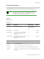
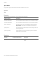
AlarmDisplay
Use AlarmDisplay to enable/disable the display of alarm messages at the console.
Use Alarms to display the alarms currently logged.
Note
Operators
modify, show
Parameters
This attribute has no output parameters.
Input Parameter
Description
Value/Field Size
[AlarmDisplay]
Toggles the display On or Off.
On, Off
Default
Descriptions
Operator
Parameters/Permissions
Description
modify
alarmdisplay
[AlarmDisplay] <alarmdisplay>
Toggles display of alarm messages on the console screen.
show
alarmdisplay
Administrator
Administrator
Displays status of alarms display.
Examples
switch_prompt # show alarmdisplay
Alarm Display is OFF
switch_prompt #
switch_prompt # modify alarmdisplay
AlarmDisplay[OFF] : on
switch_prompt #
switch_prompt # show alarmdisplay
Alarm Display is ON
switch_prompt #
SmartSwitch ATM Switch Reference Manual 2-3
Alarms
Console Commands
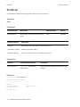
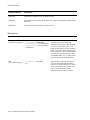
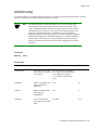
Alarms
Use Alarms to display or delete alarms currently logged.
2«ÊÍœÊ{äÊ>•>À“ÃÊ>ÀiÊ«iÀÈÃÍi˜ÍÊœ˜ÊÀiLœœÍÊ-Ài“>ˆ˜Êˆ˜Ê•œ}®°Ê!œÊiÜi˜ÍÃÊ>ÀiÊ«iÀÈÃÍi˜ÍÊœ˜Ê
ÀiLœœÍ°
Note
Operators
delete, show
Parameters
This attribute has no output parameters.
Input Parameter
Description
Value/Field Size
Default
[Index]
The index(es) of the alarms you
want to display or delete.
Positive integer or All
All
Descriptions
Operator
Parameters/Permissions
Description
delete alarms
[Index] <index>
Deletes an alarm or all alarms.
Administrator
show alarms
[Index] <index>
All
2-4 SmartSwitch ATM Switch Reference Manual
Displays alarm(s) currently logged. Alarm information
includes message index number, alarm ID, message text,
severity, and a timestamp (time the alarm occurred, with
respect to switch up-time in hours, minutes, seconds, and
milliseconds).
Console Commands
Alarms
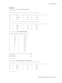
Examples
switch_prompt # show alarms
Index(ALL)
:
0 33554652 000:00:32:238
--------------------------------------------------LECS Operational
switch_1 # delete alarms
Index(ALL)
:
switch_1 # show alarms
Index(ALL)
:
SmartSwitch ATM Switch Reference Manual 2-5
Alias
Console Commands
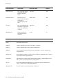
Alias
Use Alias to manage aliases for console commands. You can use up to 15 aliases.
0…iÊ>•ˆ>ÃÊpingʈÃÊ«ÀiÃi˜ÍÊÝ…i˜ÊÍ…iÊÃ݈ÍV…ʈÃÊÃ…ˆ««i`ÊvÀœ“ÊÍ…iÊv>VÍœÀßÊ-pingʈÃÊ>˜Ê>•ˆ>ÃÊ
vœÀÊstart ping®°
Note
Operators
add, delete, flush, modify, show
Parameters
Input Parameter
Description
Value/Field Size
Default
[AliasName]
Alias name.
Single word (no spaces) of
alphanumeric characters.
No default
[AliasedString]
Console command to
which alias applies.
No default
Any valid combination of
operator and attribute (for
example, show events). The
aliased string may not contain
another alias.
Output Parameter
Description
[Index]
Sequence number assigned to alias by console.
[Alias Name]
Same as the [AliasName] input parameter.
[Aliased Command]
Same as the [AliasedString] input parameter.
Descriptions
Operator
Parameters/Permissions
Description
add alias
[AliasName] <aliasname>
[AliasedString] <aliasedstring>
Creates an alias. You can have up to 15 active
aliases (including ping).
Administrator
2-6 SmartSwitch ATM Switch Reference Manual
Console Commands
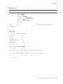
Alias
Operator
Parameters/Permissions
Description
delete alias
[AliasName] <aliasname>
Deletes an alias.
Administrator
flush alias
Administrator
Deletes all aliases (including ping).
modify alias
[AliasName] <aliasname>
[NewAliasedString] <newaliasedsring>
Changes an alias.
Administrator
show alias
Displays all aliases.
[AliasName] <aliasname>
Administrator
Examples
switch_prompt # add alias
AliasName()
AliasedString()
: spnni
: show pnniinterface
switch_prompt #
switch prompt # delete alias
AliasName()
spnni -> show pnniinterface
Confirm(y/n)?:y
: spnni
switch_prompt #
switch_prompt # flush alias
You are about to delete all aliases
Confirm(y/n)?:y
switch_prompt #
switch_prompt # modify alias
AliasName()
: spnni
NewAliasedString()
: sp
Modifying Alias "spnni -> show pnniinterface" to "spnni -> sp"
Confirm(y/n)?:y
switch_prompt #
SmartSwitch ATM Switch Reference Manual 2-7
Alias
switch_prompt # show alias
AliasName(ALL)
:
Alias List
==============================================================================
Index Alias Name
: Aliased Command
1
PING
: Start Ping
2
sp
: show pnninode
switch_prompt #
2-8 SmartSwitch ATM Switch Reference Manual
Console Commands
Console Commands
AtmFilter
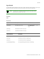
AtmFilter
Use AtmFilter to manage ATM filters on the switch.
Operators
add, delete, modify, show
Parameters
Input Parameter
Description
Value/Field Size
Default
[AtmFilterName]
Name of the filter.
15-characters
maximum
FILTERXXX, where XXX
is the index.
[AtmFilterType]
Type of the filter.
Admit, Deny
[SrcAtmAddress]
Source (calling party) address (for
which this filter should be applied).
20-bytes maximum
[SrcAtmAddressMask]
Mask of the source ATM address.
20-bytes maximum
[DstAtmAddress]
Destination (called party) address
(for which this filter should be
applied).
20 bytes maximum
[DstAtmAddressMask]
Mask of the destination ATM
address.
20-bytes maximum
Default mask is created
from the SrcAtmAddress.
Default mask is created
from the DstAtmAddress.
In the Output Parameter table below, (</d>) indicates parameters that are available only through the show
/d (detailed) command.
atmfilter
Output Parameter
Description
[FilterName]
Name of the ATM filter.
[FilterType]
Type of the ATM filter. Possible values are: Admit or Deny.
[TotalAdmits]
Number of calls that were acted on by this filter that have passed through.
[TotalDenies]
Number of calls that were acted on by this filter that have not passed through.
[ReferenceCount]
Number of filter sets that are using this filter.
SmartSwitch ATM Switch Reference Manual 2-9
AtmFilter
Console Commands
Output Parameter
Description
[Src ATM Addr] </d>
Source (calling party) address for which the filter should be applied.
[Src Addr Mask] </d>
Mask of the source ATM address.
[Dst ATM Addr] </d>
Destination (called party) address for which the filter should be applied.
[Dst Addr Mask] </d>
Mask of the destination ATM address.
Descriptions
Operator
Parameters/Permissions
Description
add atmfilter
[FilterName] <filtername>
Adds an ATM filter.
[SrcAtmAddress] <srcatmaddress>
[SrcAtmAddressMask]
<srcatmaddressmask>
[DstAtmAddress] <dstatmaddress>
[DstAtmAddressMask]
<dstatmaddressmask>
[FilterType] <filtertype>
Administrator
delete atmfilter
[FilterName] <filtername>
Deletes an ATM filter.
Administrator
modify atmfilter
[FilterName] <filtername>
[SrcAtmAddress] <srcatmaddress>
[SrcAtmAddressMask]
<srcatmaddressmask>
[DstAtmAddress] <dstatmaddress>
[DstAtmAddressMask]
<dstatmaddressmask>
[FilterType] <filtertype>
Modifies an ATM filter.
Administrator
show atmfilter
[FilterName] <filtername>
Administrator
2-10 SmartSwitch ATM Switch Reference Manual
Displays ATM filters.
Console Commands
AtmFilter
Examples
switch_prompt # add atmfilter
FilterName(FILTER1)
Src-ATMAddr()
SrcAddrMask(FF:FF:FF:FF:FF:FF)
Dst-ATMAddr()
DstAddrMask():
FilterType()
switch_prompt # add atmfilter
FilterName(FILTER2)
Src-ATMAddr()
SrcAddrMask():
Dst-ATMAddr()
DstAddrMask(FF:FF:FF:FF:FF:FF):
FilterType()
switch_prompt # add atmfilter
FilterName(FILTER3)
Src-ATMAddr()
SrcAddrMask(FF:FF:FF:FF:FF:FF:FF:FF:FF)
Dst-ATMAddr()
DstAddrMask(FF:FF:FF:FF:FF:FF):
FilterType()
: allow_src_pfx
: 39:20:10:35:00:10
:
:
: admit
: bad_dst_pfx
:
: 39:00:28:10:00:F8
: deny
: bad_src_dst_pfx
: 39:14:67:EC:0D:F1:89:93:06
:
: 39:00:28:10:00:F8
: deny
switch_prompt # add atmfilter
FilterName(FILTER4)
: deny_host
Src-ATMAddr()
: 39:14:67:EC:0D:F1:89:93:06:00:00:00:00:00:00:00:00:20:D4:01
SrcAddrMask(FF:FF:FF:FF:FF:FF:FF:FF:FF:FF:FF:FF:FF:FF:FF:FF:FF:FF:FF:FF:FF) :
Dst-ATMAddr()
:
DstAddrMask():
FilterType()
: Deny
switch_prompt # modify atmfilter
FilterName()
Src-ATMAddr(39:14:67:EC:0D:F1:89:93:06)
SrcAddrMask(FF:FF:FF:FF:FF:FF:FF:FF:FF)
Dst-ATMAddr(39:00:28:10:00:F8):
DstAddrMask(FF:FF:FF:FF:FF:FF):
FilterType(Deny)
: bad_src_dst_pfx
:
: FF:FF:FF:FF:FF:FF:FF:FF:00
:
switch_prompt # delete atmfilter
FilterName()
switch_prompt # show atmfilter
FilterName(ALL)
:deny_host
:
FilterName
FilterType TotalAdmits TotalDenies ReferenceCount
==============================================================================
allow_src_pfx
Admit
0
0
0
bad_dst_pfx
Deny
0
0
0
bad_src_dst_pfx
Deny
0
0
0
SmartSwitch ATM Switch Reference Manual 2-11
AtmFilter
switch_prompt # show atmfilter /d
FilterName(ALL)
Console Commands
:
============================================================================
Filter Name : allow_src_pfx
Src ATM Addr: 39:20:10:35:00:10
Src Addr Mask: FF:FF:FF:FF:FF:FF
Dst ATM Addr:
Dst Addr Mask:
Filter Type: Admit
Total Admits
: 0
Total Denies
: 0
Reference Count : 0
============================================================================
Filter Name : bad_dst_pfx
Src ATM Addr :
Src Addr Mask :
Dst ATM Addr: 39:00:28:10:00:F8
Dst Addr Mask : FF:FF:FF:FF:FF:FF
Filter Type : Deny
Total Admits
: 0
Total Denies
: 0
Reference Count : 0
============================================================================
Filter Name: bad_src_dst_pfx
Src ATM Addr: 39:14:67:EC:0D:F1:89:93:06
Src Addr Mask: FF:FF:FF:FF:FF:FF:FF:FF:00
Dst ATM Addr: 39:00:28:10:00:F8
Dst Addr Mask: FF:FF:FF:FF:FF:FF
Filter Type: Deny
Total Admits
: 0
Total Denies
: 0
Reference Count : 0
============================================================================
2-12 SmartSwitch ATM Switch Reference Manual
Console Commands
AtmFilterSet
AtmFilterSet
Use AtmFilterSet to manage an ATM filter set. An ATM filter set consists of one or more ATM filters. Each ATM
filter set is assigned to a pair of ports, having one incoming port and one outgoing port (alternately, you can assign a
filter set to all incoming or outgoing ports).
Operators
add, delete, modify, show
Parameters
Input Parameter
Description
Value/Field Size
[FilterName]
Name of the filter to insert or
remove from the filter set (used with
modify atmfilterset only).
[FilterSetName]
Name of the filter set.
[Operation]
Operation to perform on the filter set Insert, Remove
(used with modify atmfilterset
only).
Default
No default
In the Output Parameter table below, (</d>) indicates parameters that are available only through the show atmfilter
/d (detailed) command or if you specify a specific [FilterSetName]. In both cases, you get information about specific
filters in the filter set.
Output Parameter
Description
[FilterSetName]
Name of the filter set.
[TotalAdmits]
Total admits associated with the filter set.
[TotalDenies]
Total denies associated with the filter set.
[ReferenceCount]
Reference count associated with the filter set.
[Priority] </d>
Priority of a filter in the filter set. (Priority is assigned in the order in which
filters are added to the filter set; the first filter added becomes priority 1, the
second priority 2 and so forth. If a filter is removed from the set, each lower
priority filter has its prioiry adjusted upward one position. Filtering is done
in order of priority; the priority 1 filter is used, then priority 2 filter, and so
forth until all filters have been used.)
[FilterType] </d>
Type of a filter in the filter set.
SmartSwitch ATM Switch Reference Manual 2-13
AtmFilterSet
Output Parameter
Console Commands
Description
(If /d or a specific [FilterSetName] is specified, you also get a breakdown of TotalAdmits, TotalDenies, and
ReferenceCount for each filter in the set.)
Descriptions
Operator
Parameters/Permissions
Description
add atmfilterset
[FilterSetName] <filtersetname>
[FilterName] <filtername>
Adds an ATM filter set.
Administrator
delete atmfilterset
[FilterSetName] <filtersetname>
[FilterName] <filtername>
Deletes an ATM filter set.
Administrator
modify atmfilterset
[FilterSetName] <filtersetname>
[Operation] <operation>
[FilterName] <filtername
Modifies an ATM filter set.
Administrator
show atmfilterset
[FilterSetName] <filtersetname>
[FilterName] <filtername>
Administrator
2-14 SmartSwitch ATM Switch Reference Manual
Shows ATM filter sets.
Console Commands
AtmFilterSet
Examples
switch_prompt # show atmfilter
FilterName(ALL)
:
FilterName
FilterType TotalAdmits TotalDenies ReferenceCount
==============================================================================
filter2
Deny
0
0
0
filter3
Admit
0
0
0
switch_prompt # add atmfilterset
FilterSetName(SET1)
FilterName()
FilterName()
FilterName()
Created Filter Set (SET1) With 2 Filters
switch_prompt # show atmfilterset
FilterName(ALL)
:
: filter2
: filter3
:
:
FilterSetName
TotalAdmits TotalDenies ReferenceCount
==============================================================================
SET1
0
0
0
switch_prompt # modify atmfilterset
FilterSetName()
Operation()
FilterName()
: set1
: remove
: filter2
switch_prompt # show atmfilterset
FilterName(ALL)
: SET1
================================================================================
Filter Set Name : SET1
Total Admits
: 0
Total Denies
: 0
Reference Count : 0
================================================================================
Priority FilterName
FilterType TotalAdmits TotalDenies
==============================================================================
1
filter3
Admit
0
0
switch_prompt #
SmartSwitch ATM Switch Reference Manual 2-15
ATMRoute
Console Commands
ATMRoute
Use ATMRoute to manage routes to reachable addresses from the switch.
Note
The following applies to SmartSwitch 6500 only: You can hot-swap TSMs.
Hot-swapping is replacing a module when the chassis is powered up. If you
replace a TSM with another TSM of the same type (same I/O ports), existing
configuration of port parameters is not affected. This includes parameters set
using any of the following attributes: ATMRoute, CACServiceClassBw,
IlmiConfig, NetPrefix, Port, PortConfig, PVC, PVP, ServiceRegistry, SigTimer,
SigStatistics, SSCOPConfig, and SSCOPStatistics. If you replace a TSM with
another TSM of a different type, existing configuration of port parameters is
deleted. The deletion occurs when the new module is plugged into the chassis
backplane.
Operators
add, delete, show
Parameters
Input Parameter
Description
[Num]
Index number of the route as assigned Positive integer
by the console. Use the show
atmroute all command to get a list of
index numbers.
All
[PortNumber]
Port number on the switch. You can
specify a physical or virtual port.
All
[AtmAddr]
Address prefix of the ATM end
system.
No default
[PrefixLength]
Length in bits to apply to the address
prefix.
No default
[AddressIndex]
Index into the set of listings of
connectivity to the address prefix.
0
[Type]
Type of reachability from the switch to Exterior, Internal, Reject
the address prefix.
Internal
2-16 SmartSwitch ATM Switch Reference Manual
Value/Field Size
A1 to B4 (physical-2500 family),
A1.n to B4.n (virtual-2500 family),
1A1 to 8B4 (physical-6500),
1A1.n to 8B4.n (virtual-6500),
or All
Default
Console Commands
ATMRoute
Input Parameter
Description
[Scope]
PNNI scope of advertisement (level of Integers from 0-104
PNNI hierarchy) from the switch to the
address prefix.
0
[MetricsTag]
Index into listing of traffic parameters
that apply to connectivity from the
switch to the address prefix. If there
are no parameters associated with this
address prefix, then zero is used.
0
[Advertising]
Whether or not the local switch should Yes, No
advertise the address into the PNNI
domain. For example, use Yes for an
end station address and No for an IISP
route.
No
Note
Value/Field Size
Default
If you hot-swap a TSM with a TSM of a different type (different I/O ports), routing
information associated with ports on the original TSM is deleted. Before you
insert a replacement TSM, you can display existing routing information using the
show operator with the /o option (for example: show atmroute /o).
Output Parameter
Description
[Num]
Index number of the route as assigned by the console.
[Port]
Same as [PortNumber] input parameter.
[ATM Address]
Same as [ATMAddr] input parameter.
[Protocol]
Routing mechanism used to determine connectivity between the switch and the
reachable address prefix. Possible values are Other, Local, Mgmt, and PNNI.
[Advertising Node Id]
Identifier of the node advertising reachability to the address prefix.
[Advertising Port Id]
Identifier of the port used from the advertising node to reach the given address prefix.
[PNNI Scope]
PNNI scope of advertisement (level of PNNI hierarchy) of reachability from the switch
to the address prefix.
[VP Capability]
Indicates whether or not VPCs can be established from the advertising node to the
reachable address prefix.
SmartSwitch ATM Switch Reference Manual 2-17
ATMRoute
Console Commands
Output Parameter
Description
[Metrics Tag]
Index into the listing of traffic parameter values that apply for connectivity between the
switch and the reachable address prefix.
[Ptse Id]
For reachable addresses learned through PNNI, this parameter contains the value of the
PTSE identifier for the PTSE that is originated by the originating node and contains the
information group(s) describing the reachable address. For reachable addresses learned
by means other than PNNI, this parameter is set to zero.
[Advertising]
Whether or not the local switch advertises the local address into the PNNI domain.
Possible values are: Yes and No.
[Oper Status]
Whether or not the reachable address prefix is operationally valid and whether it is
advertised by this node. Possible values are: Advertised, Active, and Inactive.
Descriptions
Operator
Parameters/Permissions
Description
add atmroute
[PortNumber] <portnumber>
[ATMAddr] <atmaddress>
[PrefixLength] <prefixlength>
[AddressIndex] <addressindex>
[Type] <type>
[Scope] <scope>
[MetricsTag] <metricstag>
Adds a route to a reachable address from the switch.
Administrator
delete
atmroute
[PortNumber] <portnumber>
[ATMAddr] <atmaddress>
[PrefixLength] <prefixlength>
[AddressIndex] <index>
Deletes a route to a reachable address from the switch.
Administrator
show atmroute
All
Displays the configured routes from the switch.
Examples
switch_prompt # show atmroute
Num(ALL)
:
Num Port Number ATM Address
Type Proto
================================================================================
1
CPU
39:00:00:00:00:00:00:00:00:00:a3:87:0b:00:00:1d:a3:87:0b I MGMT
2
CPU
39:00:00:00:00:00:00:00:00:00:a3:87:0b:00:00:64:01:01:16 I MGMT
3
-39:00:00:00:00:00:00:00:00:00:a3:87:0b:00:20:d4:28:c1:ff I MGMT
4
CPU
47:00:79:00:00:00:00:00:00:00:00:00:00:00:a0:3e:00:00:01 I MGMT
2-18 SmartSwitch ATM Switch Reference Manual
Console Commands
ATMRoute
switch_prompt #
switch_prompt # add atmroute
PortNumber()
AtmAddress()
PrefixLength(32)
AddressIndex(0)
Type(Internal)
Scope(0)
MetricsTag(0)
Advertising(NO)
: 7a3
: 20:01:02:03
:
:
:
:
:
:
switch_prompt # show atmroute
Num(ALL)
:
Num Port Number ATM Address
Type Proto
================================================================================
1
7A3
20:01:02:03
I MGMT
2
CPU
39:00:00:00:00:00:00:00:00:00:a3:87:0b:00:00:1d:a3:87:0b I MGMT
3
CPU
39:00:00:00:00:00:00:00:00:00:a3:87:0b:00:00:64:01:01:16 I MGMT
4
-39:00:00:00:00:00:00:00:00:00:a3:87:0b:00:20:d4:28:c1:ff I MGMT
5
CPU
47:00:79:00:00:00:00:00:00:00:00:00:00:00:a0:3e:00:00:01 I MGMT
switch_prompt # delete atmroute
AtmAddress()
PrefixLength(32)
AddressIndex(0)
: 20:01:02:03
:
:
Route Address Num 0
================================================================================
Node Index
: 1
Port Number
: 7A3
ATM Address
: 20:01:02:03:00:00:00:00:00:00:00:00:00:00:00:00:00:00:00
Prefix Length
: 32
Address Index
: 0
Advertising Node: 50:a0:39:00:00:00:00:00:00:00:00:00:a3:87:0b:00:20:d4:28:c1:ff
:00
Advert Port Id : 29634560
Type
: Internal
Protocol
: MGMT
PNNI Scope
: 0
VP Capability
: False
Metrics Tag
: 0
Ptse Id
: 0
Advertising
: No
Oper Status
: Active
The ATM route was deleted successfully.
switch_prompt #
SmartSwitch ATM Switch Reference Manual 2-19
BUSClient
Console Commands
BUSClient
Use BUSClient to display or delete LANE clients connected to a BUS. Each LANE client is identified uniquely by its
LEC ID.
Operators
delete, show
Parameters
Input Parameter
Description
Value/Field Size
Default
[ELANNumber]
Number of the ELAN to which the BUS
belongs.
0-125
0
[LECId]
LEC ID of the specified client.
1-65279
0
[ATMAddress]
ATM address of the client.
Output Parameter
Description
[LECId]
LEC identification number of the specified client.
[VPI/VCI]
VPI/VCI (virtual path/channel identifier) values of control direct VCC (virtual channel
connection) or multicast send VCC.
[ATM Address]
ATM address of the client.
No default
Descriptions
Operator
Parameters/Permissions
Description
delete
busclient
[ELANNumber] <elannumber>
[LecID] <lecidvalue>
Removes a specified client from the BUS on the specified
ELAN.
Administrator
show
busclient
[ELANNumber] <elannumber>
All
2-20 SmartSwitch ATM Switch Reference Manual
Displays information about all clients that have joined the
BUS on the specified ELAN.
Console Commands
BUSClient
Examples
switch_prompt
ELANNumber(0)
LECId(0)
ATMAddress
Confirm(y/n)?
switch_prompt
#
:
:
:
:
#
delete busclient
14
39:00:00:00:00:00:00:00:20:D4:14:11:80:00:20:D4:00:D6:C0:00
y
switch_prompt # show busclient 0
Client table entries for ELAN
ELAN000
===========================================================================
LECId
VPI/VCI
ATM Address
switch_prompt
: 1
: 0/219
: 39:00:00:00:00:00:00:00:20:D4:14:2F:00:00:20:D4:14:2F:00:00
#
SmartSwitch ATM Switch Reference Manual 2-21
BUSErrorLog
Console Commands
BUSErrorLog
Use BUSErrorLog to display or clear the BUS error log associated with an ELAN.
Note
Use the add buselan or modify buselan commands to enable or disable the BUS
error log for a specified ELAN.
Operators
clear, show
Parameters
Input Parameter
Description
Value/Field Size
Default
[ELANNumber]
The number of the ELAN whose BUS errors are
to be shown or deleted.
0-125
All
Output Parameter
Description
[ATM Address]
ATM address associated with the error.
[ErrorCode]
Decimal code that shows why the error occurred (see Table 2-2).
[SysUpTime]
Time the error occurred with respect to switch up-time in hours, minutes, and seconds.
Descriptions
Operator
Parameters/Permissions
Description
delete buserrorlog
[ELANNumber] <elannumber>
Clears the BUS error log.
Administrator
show buserrorlog
Administrator
2-22 SmartSwitch ATM Switch Reference Manual
Displays the BUS error log.
Console Commands
BUSErrorLog
Table 2-2
BUSErrorLog Error Codes
Code
Name
Meaning
0
Success
Successful response.
1
Insufficient resources to grant request
Responder is unable to grant request for reasons such as
insufficient table space or ability to establish VCCs.
2
Bad control frame
Malformed control frame or bad control request.
3
Bad data frame
Malformed data frame (too big or too small).
4
Others
All other events.
Examples
switch prompt # show buserrorlog
ELANNumber(ALL)
: 1
Error Log Entries for VLAN : 1
ATM Address
ErrorCode
SysUpTime
39:1:2:3:4:5:6:7:8:9:0:1:2:3:4:5:6:7:8:9
22
01:02:03
switch prompt # clear buserrorlog
ELANNumber(ALL)
Clear BUS ELAN
Confirm (Y/N)
1
:
: 1
Error Log
Y
switch prompt # show buserrorlog
ELANNumber(ALL)
: 1
Error Log Entries for VLAN : 0
switch prompt #
SmartSwitch ATM Switch Reference Manual 2-23
BUSELAN
Console Commands
BUSELAN
Use BUSELAN to manage characteristics of a BUS for a specified ELAN. If an LES corresponding to the BUS exists,
the characteristics of the BUS should match those of the LES.
Operators
add, delete, modify, show
Parameters
Input Parameter
Description
Value/Field Size
Default
[ELANNumber]
Number of the ELAN to which the BUS
belongs.
0-125 or All
All
[ELANName]
Name of the ELAN to which the BUS belongs. Up to 32 characters
[ConnectMethod]
Type of connection used.
PVC, SVC
SVC
[ELANType]
Data-link type used by the ELAN.
802.3 (Ethernet),
802.5 (TokenRing)
802.3
[Multipoint]
Indicates whether control distribute VCC is
PMP (point-to-multipoint) or PTP
(point-to-point).
Yes: VCC is PMP
No: VCC is PTP
Yes
[MTU]
Maximum transfer unit assigned for this client.
1516, 1580, 4544, or
9234
1516
[ErrorLogEnable]
Whether or not BUS error log is enabled.
Yes, No
No
[MinimumTDEnable]
Whether or not minimum acceptable traffic
descriptor negotiation is enabled.
Yes, No
No
[ForwardPeakCellRate]
Minimum forward peak cell rate.
Positive integer
Output Parameter
Description
[ELAN Number]
Number of the ELAN to which the BUS belongs.
[ELAN Name]
Name of the ELAN to which the BUS belongs.
2-24 SmartSwitch ATM Switch Reference Manual
Console Commands
BUSELAN
Output Parameter
Description
[ATM Address]
ATM address of the ELAN.
[Max Frame Size]
Maximum transfer unit assigned for this client. (Same as the [MTU] input parameter.)
[Connection Method]
Type of connection used. (Same as the [ConnectMethod] input parameter.)
[Distribute VPI/VCI]
VPI/VCI values of control direct VCC or multicast send VCC.
[ELAN Type]
Data-link type used by the ELAN.
[Multipoint]
Indicates whether control distribute VCC is PMP (point-to-multipoint) or PTP
(point-to-point).
[Error Logging]
Whether or not BUS error log is enabled.
[Min TD Negotiation]
Whether or not minimum TD negotiation is enabled.
Descriptions
Operator
Parameters/Permissions
Description
add buselan
[ELANNumber] <elannumber>
[ELANName] <elanname>
[ConnectMethod] <connectmethod>
[ELANType] <elantype
[Multipoint] <distributevcctpe>
[MTU] <maximumframesize>
[ErrorLogEnable] <errorlogenable>
[MinimumTDEnable] <minimumtdenable>
[ForwardPeakCellRate]
<forwardpeakcellrate>
Creates a BUS on a specified ELAN. If the
corresponding LESELAN exists, then the added
BUSELAN should have similar characteristics.
Administrator
delete
[ELANNumber] <elannumber>
buselan
Administrator
modify
[ELANNumber] <elannumber>
[ELANName] <elanname>
[ConnectMethod] <connectmethod>
[ELANType] <elantype>
[Multipoint] <distributevcctpe>
[MTU] <maximumframesize>
[ErrorLogEnable] <errorlogenable>
[MinimumTDEnable] <minimumtdenable>
[ForwardPeakCellRate]
<forwardpeakcellrate>
buselan
Removes the BUS from a specified ELAN and
drops clients connected to it.
Changes the behavior of the BUS parameters for a
specified ELAN. The specified ELAN is then
deleted and recreated. If the corresponding
LESELAN exists, then the modified BUSELAN
should have the same characteristics as that
existing LESELAN because their parameters need
to match.
Administrator
SmartSwitch ATM Switch Reference Manual 2-25
BUSELAN
Console Commands
Operator
Parameters/Permissions
Description
show
[ELANNumber] <elannumber>
buselan
All
Displays the BUS parameters for the specified
ELAN. Enter show buselan to confirm that
changes you made.
Examples
switch_prompt # add buselan
ELANNumber(0)
ELANName(ELAN102)
ConnectMethod(SVC)
ELANType(802.3)
Multipoint(YES)
MTU(1516)
ErrorLogEnable(NO)
MinimumTDEnable(NO)
ForwardPeakCellRate()
: 102
:
:
:
:
:
:
:
:
switch_prompt #
switch_prompt # delete buselan
ELANNumber(0) : 3
ELAN Number
: 3
ELAN Name
: ELAN003
ATM Address
: 39:00:00:00:00:00:00:00:20:D4:14:15:00:00:20:D4:14:15:03:02
Confirm(y/n)? : y
switch_prompt #
2-26 SmartSwitch ATM Switch Reference Manual
Console Commands
BUSELAN
The example below changes ELAN102 from an Ethernet BUSELAN to a Token Ring BUSELAN, changing the MTU
to reflect the change in ELAN type. It assumes the LES has already been changed.
switch_prompt # modify buselan 102
ELANName(ELAN102)
ConnectMethod(svc)
ELANType(802.3)
Multipoint(yes)
MTU(1516)
ErrorlogEnable(NO)
MinimumTDEnable(NO)
:
:
: 802.5
:
: 4544
:
:
switch_prompt #
switch_prompt # show buselan 102
ELAN: ELAN102
ELAN Number
:
ELAN Name
:
ATM Address
:
Max Frame Size
:
Connection Method
:
Distribute VPI/VCI
:
Sel.DistributeVPI/VCI:
ELAN Type
:
Multipoint
:
Error Logging
:
Min TD Negotiation
:
102
ELAN102
39:00:00:00:00:00:00:00:20:D4:14:15:00:00:20:D4:14:15:66:02
4544
SVC
0/2423
0/2423
802.5
YES
NO
NO
switch_prompt #
SmartSwitch ATM Switch Reference Manual 2-27
BUSLECStat
Console Commands
BUSLECStat
Use BUSLECStat to display traffic statistics for clients connected to a BUS.
Operator
show
Parameters
Input Parameter
Description
Value/Field Size
Default
[ELANNumber]
Number of the ELAN to which the BUS belongs.
0-125 or All
All
[LECId]
LEC identification number of the specified client.
0-65279
0
Output Parameter
Description
[LECId]
LEC identification number of the specified client.
[ATMAddress]
ATM address of the client.
[Receives]
Number of multicast and broadcast and unknown forward requests received by the
BUS from this LEC.
[Forwards]
Number of requests forwarded by the BUS from this LEC.
[Discards]
Number of requests discarded by the BUS from this LEC.
Descriptions
Operator
Parameters/Permissions
Description
show
[ELANNumber] <elannumber>
[LecId] <lecidvalue>
Displays statistical information about a specific client or all
clients on that ELAN.
buslecstat
All
2-28 SmartSwitch ATM Switch Reference Manual
Console Commands
BUSLECStat
Examples
switch_prompt # show buslecstat
ELANNumber(0) :
LECId(0)
:
Client statistics for ELAN ELAN000
===========================================================================
LECId
: 1
ATM address
: 39:00:00:00:00:00:00:00:20:D4:14:2F:00:00:20:D4:14:2F:00:00
Receives
: 17185
Forwards
: 17185
Discards
: 0
switch_prompt #
SmartSwitch ATM Switch Reference Manual 2-29
BUSStat
Console Commands
BUSStat
Use BUSStat to display or clear statistics of a BUS for an ELAN.
Operators
show, clear
Parameters
Input Parameter
Description
Value/Field Size
[ELANNumber]
Number of the ELAN to which the BUS belongs. 0-125 or All
Output Parameter
Description
[Out Octets]
Number of octets (bytes) the BUS has sent since its initialization.
[Out Unicast]
Number of unicast frames forwarded by the BUS.
[Out Multicast]
Number of multicast frames forwarded by the BUS.
[In Octets]
Number of octets (bytes) the BUS has received since its initialization.
[In Unicast]
Number of unicast frames received by the BUS.
[In Multicast]
Number of multicast frames received by the BUS.
[Frame Timeouts]
Number of frames dropped by the BUS due to timeout.
[VCC Rejects]
Number of frames rejected because VCC is not available.
Default
All
Descriptions
Operator
Parameters/Permissions
Description
show
[ELANNumber] <elannumber>
Displays BUS statistics for the specified ELAN or for all ELANs.
busstat
All
clear
[ELANNumber] <elannumber>
busstat
Administrator
2-30 SmartSwitch ATM Switch Reference Manual
Clears BUS statistics for the specified ELAN or for all ELANs.
Console Commands
BUSStat
Examples
switch_prompt # show busstat 3
ELAN ELAN003 Statistics
Out Octets
: 450432
Out Unicast
: 7030
Out Multicast
: 3
In Octets
: 450432
In Unicast
: 7030
In Multicast
: 3
Frame Timeouts
: 0
VCC Rejects
: 0
switch_prompt #
switch_prompt # clear busstat
ELANNumber(ALL):
Clearing ALL BUS ELAN Statistics
Confirm(y/n)?:y
switch_prompt #
SmartSwitch ATM Switch Reference Manual 2-31
BUStype
Console Commands
BUStype
Use BUStype to enable/disable intelligent BUS mode.
Note
If intelligent BUS mode is enabled, a unicast packet sent to the BUS is forwarded
only to the LANE client whose destination address is specified in the packet. If
intelligent BUS mode is not enabled, a unicast packet sent to the BUS is forwarded
to all LANE clients connected to the BUS.
Operators
modify
Parameters
This attribute has no output parameters.
Input Parameter
Description
Value/Field Size
Default
[IntelligentBUSMode]
Enables/disables intelligent BUS mode.
Off, On
Off
Descriptions
Operator
Parameters/Permissions
Description
modify bustype
[IntelligentBUSMode]
<intelligentbusmode>
Sets intelligent BUS mode.
Administrator
Examples
switch_prompt # modify bustype
IntelligentBUSMode(OFF)
BUS Type Set to Intelligent Mode
switch_prompt #
2-32 SmartSwitch ATM Switch Reference Manual
: on
Console Commands
CACEqBwAllocScheme
CACEqBwAllocScheme
Use CACEqBwAllocScheme to set or display the equivalent bandwidth allocation scheme of switch ports.
Operators
modify, show
Parameters
Input Parameter
Description
Value/Field Size
Default
[PortNumber]
Port number on the switch.
You can specify a physical
or virtual port.
A1 to B4 (physical-2500 family),
A1.n to B4.n (virtual-2500 family),
1A1 to 8B4 (physical-6500),
1A1.n to 8B4.n (virtual-6500),
or All
All
[ServiceCategory]
Service category.
CBR, UBR, RTVBR, NRTVBR or
ABR
CBR
[AllocScheme]
Allocation scheme for
connection admission.
CON (conservative), LIB (liberal),
MOD (moderate)
CON
Output Parameter
Description
[Port#]
Port number on the switch. (Same as the [PortNumber] input parameter.)
[Alloc Scheme]
Allocation scheme for connection admission for each service category.
Descriptions
Operator
Parameters/Permissions
Description
modify
[PortNumber] <portnumber>
[ServiceCategory] <servicecategory>
[AllocScheme] <allocscheme>
Sets allocation scheme.
caceqbwallocscheme
Administrator
show
Administrator
Displays allocation scheme.
caceqbwallocscheme
SmartSwitch ATM Switch Reference Manual 2-33
CACEqBwAllocScheme
Examples
switch_prompt # show caceqbwallocscheme
PortNumber(ALL)
:
===========================================================
Port#
Alloc Scheme
for
CBR
RTVBR
NRTVBR
UBR
ABR
===========================================================
7A1
CON
CON
CON
LIB
CON
7A1.1
CON
CON
CON
LIB
CON
7A2
CON
CON
CON
LIB
CON
7A3
CON
CON
CON
LIB
CON
7A4
CON
CON
CON
LIB
CON
7B1
CON
CON
CON
LIB
CON
7B2
CON
CON
CON
LIB
CON
7B3
CON
CON
CON
LIB
CON
CPU
CON
CON
CON
LIB
CON
CPU.1
CON
CON
CON
LIB
CON
switch_prompt #
switch_prompt # modify caceqbwallocscheme
PortNumber()
: 7a1
SeriveCategory(CBR)
: nrtvbr
AllocScheme(CONSERVATIVE)
: liberal
switch_prompt #
switch_prompt # show caceqbwallocscheme
PortNumber(ALL)
:
===========================================================
Port#
Alloc Scheme
for
CBR
RTVBR
NRTVBR
UBR
ABR
===========================================================
7A1
CON
CON
LIB
LIB
CON
7A1.1
CON
CON
CON
LIB
CON
7A2
CON
CON
CON
LIB
CON
7A3
CON
CON
CON
LIB
CON
7A4
CON
CON
CON
LIB
CON
7B1
CON
CON
CON
LIB
CON
7B2
CON
CON
CON
LIB
CON
7B3
CON
CON
CON
LIB
CON
CPU
CON
CON
CON
LIB
CON
CPU.1
CON
CON
CON
LIB
CON
switch_prompt #
2-34 SmartSwitch ATM Switch Reference Manual
Console Commands
Console Commands
CacInfo
CacInfo
Use CacInfo to display bandwidth allocated to switch ports per service category.
Operators
show
Parameters
Input Parameter
Description
Value/Field Size
Default
[PortNumber]
Port number on the switch.
You can specify a physical
or virtual port.
A1 to B4 (physical-2500 family),
A1.n to B4.n (virtual-2500 family),
1A1 to 8B4 (physical-6500),
1A1.n to 8B4.n (virtual-6500),
or All
All
[BandwidthUnit]
Unit for specifying
bandwidth.
CPS (cells per second),
KBS (Kbits per second),
MBS (Mbits per second),
or PER (percentage)
CPS
Output Parameter
Description
[Port#]
Port number on the switch. (Same as the [PortNumber] input parameter.)
[Total BW]
Available physical link bandwidth (in bandwidth units specified as input parameter).
[Total BW Allocated]
Bandwidth allocated on this port.
[BwAlloc for
ServiceCategory]
Bandwidth allocated for each service category. Supported service categories are:
CBR (constant bit rate), UBR (unspecified bit rate), RTVBR (realtime variable bit
rate), NRTVBR (non-realtime variable bit rate), ABR (available bit rate).
Descriptions
Operator
Parameters/Permissions
Description
show cacinfo
[PortNumber] <portnumber>
[BandWidthUnit] <bandwidthunit>
Displays port bandwidth per service category.
Administrator
SmartSwitch ATM Switch Reference Manual 2-35
CacInfo
Examples
switch_prompt # show cacinfo
PortNumber(ALL)
: ALL
BandWidthUnit(CPS)
: CPS
=====================================================================
Port#
Total
Total BW
BwAlloc For ServiceCategory
BW
Allocated
CBR
RT-VBR
NRT-VBR UBR
ABR
=====================================================================
1A1
264186
10
0
0
0
10
0
1A2
264186
0
0
0
0
0
0
1A3
264186
10
0
0
0
10
0
1A4
264186
0
0
0
0
0
0
4B1
264186
0
0
0
0
0
0
4B2
264186
0
0
0
0
0
0
4B3
264186
0
0
0
0
0
0
switch_prompt #
2-36 SmartSwitch ATM Switch Reference Manual
Console Commands
Console Commands
CACPortBw
CACPortBw
Use CACPortBw to display minimum and maximum bandwidth of switch ports.
Operators
show
Parameters
Input Parameter
Description
Value/Field Size
Default
[PortNumber]
Port number on the switch.
You can specify a physical
or virtual port.
A1 to B4 (physical-2500 family),
A1.n to B4.n (virtual-2500 family),
1A1 to 8B4 (physical-6500),
1A1.n to 8B4.n (virtual-6500),
or All
All
Output Parameter
Description
Q+œÀÍ›R
+œÀÍʘ֓LiÀÊœ˜ÊÍ…iÊÃ݈ÍV…°ÊÊ-.>“iÊ>ÃÊÍ…iÊQ+œÀÍ!Ö“LiÀRʈ˜«ÖÍÊ«>À>“iÍiÀ°®
Q >Þ*>˜`݈`Í…7˜ L«ÃR
>Þˆ“Ö“ÊL>˜`݈`Í…Ê>••œV>Íi`ÊÍœÊÍ…ˆÃÊ«œÀÍʈ˜Ê i}>*ˆÍÃÊ«iÀÊÃiVœ˜`°
Q >Þ*>˜`݈`Í…7˜=L«ÃR
>Þˆ“Ö“ÊL>˜`݈`Í…Ê>••œV>Íi`ÊÍœÊÍ…ˆÃÊ«œÀÍʈ˜Ê=ˆ•œ*ˆÍÃÊ«iÀÊÃiVœ˜`°
Q >Þ*>˜`݈`Í…7˜+«ÃR
>Þˆ“Ö“ÊL>˜`݈`Í…Ê>••œV>Íi`ÊÍœÊÍ…ˆÃÊ«œÀÍʈ˜ÊVi••ÃÊ«iÀÊÃiVœ˜`°
Q >Þ*>˜`݈`Í…7˜+iÀR
>Þˆ“Ö“ÊL>˜`݈`Í…Ê>••œV>Íi`ÊÍœÊÍ…ˆÃÊ«œÀÍʈ˜Ê«iÀVi˜Í>}i°
Q ˆ˜*>˜`݈`Í…7˜ L«ÃR
ˆ˜ˆ“Ö“ÊL>˜`݈`Í…Ê>••œV>Íi`ÊÍœÊÍ…ˆÃÊ«œÀÍʈ˜Ê i}>*ˆÍÃÊ«iÀÊÃiVœ˜`°
Q ˆ˜*>˜`݈`Í…7˜=L«ÃR
ˆ˜ˆ“Ö“ÊL>˜`݈`Í…Ê>••œV>Íi`ÊÍœÊÍ…ˆÃÊ«œÀÍʈ˜Ê=ˆ•œ*ˆÍÃÊ«iÀÊÃiVœ˜`°
Q ˆ˜*>˜`݈`Í…7˜+«ÃR
ˆ˜ˆ“Ö“ÊL>˜`݈`Í…Ê>••œV>Íi`ÊÍœÊÍ…ˆÃÊ«œÀÍʈ˜ÊVi••ÃÊ«iÀÊÃiVœ˜`°
Q ˆ˜*>˜`݈`Í…7˜+iÀR
>Þˆ“Ö“ÊL>˜`݈`Í…Ê>••œV>Íi`ÊÍœÊÍ…ˆÃÊ«œÀÍʈ˜Ê«iÀVi˜Í>}i°
SmartSwitch ATM Switch Reference Manual 2-37
CACPortBw
Console Commands
Descriptions
Operator
Parameters/Permissions
Description
show
Administrator
Displays minimum and maximum port bandwidth.
CACPortBw
Examples
switch_prompt # show cacportbw
PortNumber(ALL)
:
=============================================================================
Port#
Max Bandwidth
|
Min Bandwidth
In
|
In
Mbps
Kbps
Cps
% | Mbps Kbps
Cps
%
=============================================================================
7A1
154
158208 422668 99
0
0
0
0
7A2
154
158208 422668 99
0
0
0
0
7A3
154
158208 422668 99
0
0
0
0
7A4
154
158208 422668 99
0
0
0
0
7B1
154
158208 422668 99
0
0
0
0
7B2
154
158208 422668 99
0
0
0
0
7B3
154
158208 422668 99
0
0
0
0
CPU
154
158208 422668 99
0
0
0
0
CPU.1
10
10752
28992
6
0
0
0
0
switch_prompt #
2-38 SmartSwitch ATM Switch Reference Manual
Console Commands
CACServiceClassBw
CACServiceClassBw
Use CACServiceClassBw to set or display the bandwidth allocated to each service category.
Note
The following applies to SmartSwitch 6500 only: You can hot-swap TSMs.
Hot-swapping is replacing a module when the chassis is powered up. If you
replace a TSM with another TSM of the same type (same I/O ports), existing
configuration of port parameters is not affected. This includes parameters set
using any of the following attributes: ATMRoute, CACServiceClassBw,
IlmiConfig, NetPrefix, Port, PortConfig, PVC, PVP, ServiceRegistry, SigTimer,
SigStatistics, SSCOPConfig, and SSCOPStatistics. If you replace a TSM with
another TSM of a different type, existing configuration of port parameters is
deleted. The deletion occurs when the new module is plugged into the chassis
backplane.
Operators
modify, show
Parameters
Input Parameter
Description
Value/Field Size
Default
[PortNumber]
Port number on the switch.
You can specify a physical
or virtual port.
A1 to B4 (physical-2500 family),
A1.n to B4.n (virtual-2500 family),
1A1 to 8B4 (physical-6500),
1A1.n to 8B4.n (virtual-6500),
or All
[ServiceCategory]
.iÀ܈ViÊV>Íi}œÀß°
CBR, UBR, RTVBR, NRTVBR, ABR UBR
[MaxBandwidthInPerCBR]
>Þˆ“Ö“ÊL>˜`݈`Í…Ê
Zero or positive integer
>••œV>Íi`ÊvœÀÊ+*-°Ê-0œÍ>•ÊœvÊ
>••ÊÍ…iÊÃiÀ܈ViÊV>Íi}œÀßÊ
L>˜`݈`Í…ÊÃ…œÖ•`ʘœÍÊ
iÞVii`Ê£ä䯰®
[MaxBandwidthInPercentage
RTVBR]
Maximum bandwidth
allocated for RTVBR.
Zero or positive integer
[MaxBandwidthInPercentage
NRTVBR]
>Þˆ“Ö“ÊL>˜`݈`Í…Ê
>••œV>Íi`ÊvœÀÊ!-07*-°
Zero or positive integer
SmartSwitch ATM Switch Reference Manual 2-39
CACServiceClassBw
Console Commands
Input Parameter
Description
Value/Field Size
[MaxBandwidthInPercentage
UBR]
Maximum bandwidth
allocated for UBR.
Zero or positive integer
[MaxBandwidthInPercentage
ABR]
Maximum bandwidth
allocated for ABR.
Zero or positive integer
Output Parameter
Description
[Port#]
Port number on the switch. (Same as [PortNumber] input parameter.
[SC]
Service category. (Same as [ServiceCategory] input parameter.)
Default
[Max Bandwidth In Mbps) Maximum bandwidth in MegaBits per second allocated to the service category
specified.
[Max Bandwidth In Kbps)
Maximum bandwidth in KiloBits per second allocated to the service category
specified.
[Max Bandwidth In Cps]
Maximum bandwidth in cells per second allocated to the service category specified.
[Max Bandwidth In %]
Maximum bandwidth in percent allocated to the service category specified.
Descriptions
Operator
Parameters/Permissions
Description
modify
[PortNumber] <portnumber>
[ServiceCategory] <servicecategory>
[BandwidthUnit] <bandwidthunit>
[MaxBandwidthInPercentageCBR]
<maxbandinpercbr>
[MaxBandwidthInPercentageRTVBR]
<maxbandinperrtvbr>
[MaxBandwidthInPercentageNRTVBR]
<maxbandinpernrtvbr>
[MaxBandInPercentageUBR]
<maxbandinperubr>
[MaxBandInPercentageABR]
<maxbandinperabr>
[MaxBandwidth] <maxbandwidth>
Sets bandwidth per service category.
cacserviceclassbw
Administrator
show
Administrator
cacserviceclassbw
2-40 SmartSwitch ATM Switch Reference Manual
Displays bandwidth per service class.
Console Commands
CACServiceClassBw
Examples
switch_prompt # modify cacServiceClassBW
PortNumber()
MaximumBandWidthIn-Percentage-CBR(25)
MaximumBandWidthIn-Percentage-RTVBR(25)
MaximumBandWidthIn-Percentage-NRTVBR(25)
MaximumBandWidthIn-Percentage-UBR(25)
MaximumBandWidthIn-Percentage-ABR(0)
: 1b1
:
:
:
:
:
switch_prompt #
switch_prompt #show cacServiceClassBW
PortNumber(ALL)
SeriveCategory(UBR)
: 1a1
: CBR
===========================================
Port#
SC
Max Bandwidth
In
Mbps Kbps
Cps
%
===========================================
1A1
CBR
1
1
1
1
switch_prompt #
SmartSwitch ATM Switch Reference Manual 2-41
CACStatistics
Console Commands
CACStatistics
Use CACStatistics to show CAC statistics for switch ports.
Operators
clear, show
Parameters
Input Parameter
Description
Value/Field Size
Default
[PortNumber]
Port number on the switch.
You can specify a physical
or virtual port.
A1 to B4 (physical-2500 family),
A1.n to B4.n (virtual-2500 family),
1A1 to 8B4 (physical-6500),
1A1.n to 8B4.n (virtual-6500),
or All
All
Output Parameter
Description
[Port Number]
Physical or virtual port number on the switch.
[Global Statistics]
Global CAC statistics (applies to all ports).
[Per Port Statistics]
Statistics for a specific port.
Descriptions
Operator
Parameters/Permissions
Description
clear
[PortNumber] <portnumber>
Clears CAC statistics of a port or all ports.
cacstatistics
Administrator
show
[PortNumber] <portnumber>
cacstatistics
Administrator
Examples
2-42 SmartSwitch ATM Switch Reference Manual
Displays CAC statistics of a port or all ports.
Console Commands
switch_prompt # show cacstatistics
PortNumber()
CACStatistics
: 1a1
================================================================
CAC Statistics
================================================================
Global Statistics :
No of Rejections due to no memory
:0
No of Rejections due to Invalid Physical port
:0
No of Rejections due to Invalid logical port
:0
No of Rejections due to Invalid VPI
:0
No of Rejections due to Pre CAC no memory
:0
Per Port Statistics :
Port Number
No of calls rejected due to User cell rate unavailable
No of calls rejected due to Sytem Low Memory
No of calls rejected due to Link Down
No of calls rejected due to VPCI/VCI unavailable
No of calls rejected due to Unsupported traffic params
No of CBR calls rejected
No of RT_VBR calls rejected
No of NRT_VBR calls rejected
No of UBR calls rejected
No of ABR calls rejected
No of CBR calls HIGH threshold exceeded
No of CBR calls LOW threshold exceeded
No of RT_VBR calls HIGH threshold exceeded
No of RT_VBR calls LOW threshold exceeded
No of NRT_VBR calls HIGH threshold exceeded
No of NRT_VBR calls LOW threshold exceeded
No of UBR calls HIGH threshold exceeded
No of UBR calls LOW threshold exceeded
No of ABR calls HIGH threshold exceeded
No of ABR calls LOW threshold exceeded
No of PNNI Updates sent
Total No of calls HIGH threshold exceeded
Total No of calls LOW threshold exceeded
:1A1
:0
:0
:0
:0
:0
:0
:0
:0
:0
:0
:0
:0
:0
:0
:0
:0
:0
:0
:0
:0
:0
:0
:0
switch_prompt #
SmartSwitch ATM Switch Reference Manual 2-43
Client
Console Commands
Client
Use Client to manage LANE and IP/ATM clients on the switch. Clients on the switch are called local clients.
Note
Use the LANEClient attribute to add or modify a LANE client. Use the
IPATMClient attribute to add or modify an IP/ATM client.
Operators
activate, deactivate, delete, restart, show
Parameters
Input Parameter
Description
Value/Field Size
Default
[ClientNumber]
Number of the local client.
0-125 or All
All
In the Output Parameter table below, (</d>) appears next to parameters that are available only through the
client /d (detailed) command.
show
Output Parameter
Description
[Client]
Number of the local client. (Same as the [ClientNumber] input parameter.)
[Type]
Type of client.
[IP Address]
IP address of client.
[Server Type]
Specifies what server type the client is on.
[Server Conn]
Status of connection the client has with the server. Possible values are:
Established and Shutdown.
[Status]
Current status of the client.
[Client State] </d>
Status of where the client is in the process of making a connection.
[Client Address] </d>
ATM address of the client.
[LAN Name] </d>
ELAN name for this client.
[LECS Addr Source] </d>
ILMI, well-known address, or LECS address.
2-44 SmartSwitch ATM Switch Reference Manual
Console Commands
Client
Output Parameter
Description
[LECS Address] </d>
ATM address of the LECS.
[LES Address] </d>
ATM address of the LES.
[LAN Type] </d>
Type of ELAN.
[MTU] </d>
Maximum transfer unit assigned for this client.
[IP NetMask] </d>
IP netmask assigned to the client.
Descriptions
Operator
Parameters/Permissions
Description
activate
client
[ClientNumber] <clientnumber>
Activates a client on the switch (same as the restart
command).
deactivate
client
[ClientNumber] <clientnumber>
delete
[ClientNumber] <clientnumber>
client
Administrator
restart
[ClientNumber] <clientnumber>
client
Administrator
show client
[ClientNumber] <clientnumber>
(/d)
All
Administrator
client
Deactivates a client on the switch.
Administrator
Removes a client from the switch.
Restarts a client on the switch. If a client fails to successfully
join a VLAN, you can restart the client to retry. The switch
software, on a periodic basis, automatically tries to restart
clients that have not successfully joined. Enter show client
to confirm that the client(s) have restarted.
Displays the details of a client on the switch. You can obtain
more details of all the clients on the switch by adding /d to
the end of the command. For example, show client /d.
SmartSwitch ATM Switch Reference Manual 2-45
Client
Console Commands
Examples
switch_prompt # delete client 4
IP/ATM Client4 Address: 39:00:00:00:00:00:00:00:00:00:14:15:00:00:00:7A:01:01:5B:00
Confirm(y/n)?:y
switch_prompt #
switch_prompt # show client
ClientNumber(ALL)
:
Client Type
IP Address
Server Type Server Conn Status
============================================================================
1 LANE
90.1.1.186
LECS
Established Operational
3 IP/ATM 90.1.1.124
Local
Established Operational
switch_prompt #
switch_prompt # restart client
ClientNumber(ALL)
:
switch_prompt #
switch_prompt # show client
ClientNumber(ALL)
:
Client Type
IP Address
Server Type Server Conn Status
============================================================================
1 LANE
90.1.1.186
LECS
Shutdown
Initial
3 IP/ATM 90.1.1.124
Local
Shutdown
Initial
switch_prompt #
switch_prompt # show client /s
ClientNumber(ALL) :
Client Type
IP Address
Server Type Server Conn Status
============================================================================
1 LANE
90.1.1.186
LECS
Established Operational
3 IP/ATM 90.1.1.124
Local
Established Operational
switch_prompt #
2-46 SmartSwitch ATM Switch Reference Manual
Console Commands
Client
With the following example (</d>), notice how you get the same amount of detail whether you specify the client or
accept the default (All):
switch_prompt # show client /d
ClientNumber(ALL) :
LANE Client 1
============================================================================
Client State
: Operational
Client Address : 39:00:00:00:00:00:00:00:00:00:14:15:00:00:20:D4:14:15:00:00
LAN Name
: elan1
LECS Addr Source: ILMI
LECS Address
: 39:00:00:00:00:00:00:00:00:00:14:15:00:00:20:D4:14:15:00:01
LES Address
: 39:00:00:00:00:00:00:00:00:00:14:15:00:00:20:D4:14:15:00:02
LAN Type
: 802.3
MTU
: 1516
IP Address
: 90.1.1.186
IP NetMask
: 255.255.255.0
IP/ATM Client 3
============================================================================
Client State
: Operational
Client Address : 39:00:00:00:00:00:00:00:00:00:14:15:00:00:00:5A:01:01:7C:00
Server
: is local
Server Connection: Established
MTU
: 9180
IP Address
: 90.1.1.124
IP NetMask
: 255.0.0.0
switch_prompt #
switch_prompt # show client 3 /d
IP/ATM Client 3
============================================================================
Client State
: Operational
Client Address : 39:00:00:00:00:00:00:00:00:00:14:15:00:00:00:5A:01:01:7C:00
Server
: is local
Server Connection: Established
MTU
: 9180
IP Address
: 90.1.1.124
IP NetMask
: 255.0.0.0
switch_prompt #
SmartSwitch ATM Switch Reference Manual 2-47
ClientARP
Console Commands
ClientARP
Use ClientARP to display the ARP table maintained by each LANE or IP/ATM client on the switch. For a LANE client,
the table contains mappings of MAC to ATM addresses for destination clients. The mappings are supplied by the ARP
server of each ELAN to which the LANE client connects. For an IP/ATM client, the table contains mappings of IP to
ATM addresses for destination clients. The mappings are supplied by the ARP server of each IP/ATM VLAN to which
the IP/ATM client connects. The LANE and IP/ATM clients cache the mappings to avoid repeated address resolution
requests to ARP servers.
Note
Clients on the switch are called local clients.
Operators
show
Parameters
Input Parameter
Description
Value/Field Size
Default
[ClientNumber]
Number of the local client.
0-125 or All
All
Output Parameter
Description
[MAC Address]
MAC address of the LANE destination client.
[IP Address]
IP address of the IP/ATM destination client.
[ATM Address]
ATM address of the LANE or IP/ATM destination client.
Descriptions
Operator
Parameters/Permissions
Description
show
[ClientNumber] <clientnumber>
Displays details about LANE or IP/ATM client ARP entries.
clientarp
All
2-48 SmartSwitch ATM Switch Reference Manual
Console Commands
ClientARP
Examples
switch_prompt # show clientarp
ClientNumber(ALL) :
LANE Client 0 ARP Table
MAC Address
ATM Address
=============================================================================
00:20:D4:14:15:00 39:00:00:00:00:00:00:00:20:D4:14:15:00:00:20:D4:14:15:00:02
IP/ATM Client 3 ARP Table
IP Address
ATM Address
=========================================================================================
10.1.1.1
39:00:00:00:00:00:00:00:20:D4:14:15:00:00:20:D4:14:2F:00:00:0A:01:01:02:00
switch_prompt #
SmartSwitch ATM Switch Reference Manual 2-49
ClientStat
Console Commands
ClientStat
Use ClientStat to display packet count statistics of LANE or IP/ATM clients on the switch.
Note
Clients on the switch are called local clients.
Operators
show
Parameters
Input Parameter
Description
Value/Field Size
Default
[ClientNumber]
Number of the local client.
0-125 or All
All
In the Output Parameter table below, (</d>) appears next to parameters that are available only through the show
clientstat /d (detailed) command. The (IP/ATM) and (LANE) client indicators after particular parameters indicate
that these parameters display only if that particular client type is active.
Output Parameter
Description
[Client]
Number of the client. (Same as the [ClientNumber] input parameter.)
[Type]
Type of client.
[RxPkts]
Number of packets received.
[TxPkts]
Number of packets transmitted.
[RxOctets]
Number of octets (bytes) received.
[TxOctets]
Number of octets (bytes) transmitted.
[Bytes Received] </d>
Number of bytes received.
[Unicast Packets] </d>
Number of unicast packets received or transmitted.
[Multicast Packets] </d>
Interface maximum transfer unit to assign to the local interface associated
with this client.
[Broadcast Packets] </d>
Number of broadcast packets received or transmitted.
2-50 SmartSwitch ATM Switch Reference Manual
Console Commands
ClientStat
Output Parameter
Description
[Error Packets] </d>
Number of error packets received or transmitted.
[Dropped Packets] </d>
Number of received or transmitted packets dropped.
[Bytes Transmitted] </d>
Number of bytes transmitted.
[ARP Requests Sent] </d>
ARP requests from a server sent to the client.
[ARP Replies Rcvd] </d>
ARP replies from a client received by the server.
[ARP Requests Rcvd] </d>
ARP requests from a client received by the server.
[ARP Replies Sent] </d>
ARP replies from a server sent to the client.
[Ctrl Frames Sent] (LANE) </d>
Number of control frames sent.
[Ctrl Frames Rcvd] (LANE) </d>
Number of control frames received.
[SVC Failures] (LANE) </d>
Number of clients who failed to join the SVC (switched virtual circuit).
[ARP Unreachables] (IP/ATM) </d>
ARP unreachable clients.
[ARP NAKs] (IP/ATM) </d>
Number of inverse ARP NAKs (negative acknowledges) received.
[Echo Discards] </d>
Number of echo discards.
[Filtered Multicasts] </d>
Number of filtered multicasts.
[Flow Failures] </d>
Number of flow failures.
Descriptions
Operator
Parameters/Permissions
Description
show
[ClientNumber] <clientnumber>
Displays packet count statistics for local clients.
clientstat
All
Examples
The examples show statistics for all clients, detail (</d>) for all clients, an IP/ATM client, and a LANE client.
switch_prompt # show clientstat
ClientNumber(ALL):
SmartSwitch ATM Switch Reference Manual 2-51
ClientStat
Client Type
RxPkts
TxPkts
RxOctets
TxOctets
============================================================================
1 LANE
0
0
0
0
3 IP/ATM
0
0
0
0
switch_prompt #
switch_prompt # show clientstat /d
ClientNumber(ALL):
Stats for LANE client 1
============================================================================
Rx Stats
Bytes Received
: 0
Unicast Packets
: 0
Multicast Packets
: 0
Broadcast Packets
: 0
Error Packets
: 0
Dropped Packets
: 0
Tx Stats
Bytes Transmitted
: 0
Unicast Packets
: 0
Multicast Packets
: 0
Broadcast Packets
: 0
Error Packets
: 0
Dropped Packets
: 0
LAN Emulation Statistics
ARP Requests Sent
: 3
ARP Replies Rcvd
: 3
ARP Requests Rcvd
: 0
ARP Replies Sent
: 0
Ctrl Frames Sent
: 9
Ctrl Frames Rcvd
: 9
SVC Failures
: 0
Stats for IP/ATM client 3
============================================================================
Rx Stats
Bytes Received
: 0
Unicast Packets
: 0
Multicast Packets
: 0
Broadcast Packets
: 0
Error Packets
: 0
Tx Stats
Bytes Transmitted
: 0
Unicast Packets
: 0
Multicast Packets
: 0
Broadcast Packets
: 0
Error Packets
: 0
Dropped Packets
: 0
IP/ATM Statistics
ARP Requests Sent
: 0
ARP Replies Rcvd
: 0
ARP Requests Rcvd
: 0
ARP Replies Sent
: 0
ARP Unreachables
: 0
ARP NAKs
: 0
switch_prompt # show clientstat 3
2-52 SmartSwitch ATM Switch Reference Manual
Console Commands
Console Commands
ClientStat
Stats for IP/ATM client 3
============================================================================
Rx Stats
Bytes Received
: 0
Unicast Packets
: 0
Multicast Packets
: 0
Broadcast Packets
: 0
Error Packets
: 0
Dropped Packets
: 0
Tx Stats
Bytes Transmitted
: 0
Unicast Packets
: 0
Multicast Packets
: 0
Broadcast Packets
: 0
Error Packets
: 0
Dropped Packets
: 0
IP/ATM Statistics
ARP Requests Sent
: 0
ARP Replies Rcvd
: 0
ARP Requests Rcvd
: 0
ARP Replies Sent
: 0
ARP Unreachables
: 0
ARP NAKs
: 0
switch_prompt #
switch_prompt # show clientstat 1
Stats for LANE client 1
============================================================================
Rx Stats
Bytes Received
: 0
Unicast Packets
: 0
Multicast Packets
: 0
Broadcast Packets
: 0
Error Packets
: 0
Dropped Packets
: 0
Tx Stats
Bytes Transmitted
: 0
Unicast Packets
: 0
Multicast Packets
: 0
Broadcast Packets
: 0
Error Packets
: 0
Dropped Packets
: 0
LAN Emulation Statistics
ARP Requests Sent
: 3
ARP Replies Rcvd
: 3
ARP Requests Rcvd
: 0
ARP Replies Sent
: 0
Ctrl Frames Sent
: 9
Ctrl Frames Rcvd
: 9
SVC Failures
: 0
switch_prompt #
SmartSwitch ATM Switch Reference Manual 2-53
ClientVC
Console Commands
ClientVC
Use ClientVC to display VCs associated with ARP mappings cached by LANE or IP/ATM clients on the switch.
ClientARP is similar to ClientVC but does not show the VPI/VCI corresponding to a route to a destination client.
Note
Clients on the switch are called local clients.
Operator
show
Parameters
Input Parameter
Description
Value/Field Size
Default
[ClientNumber]
Number of the local client.
0-125 or All
All
Output Parameter
Description
[MAC Address]
MAC address of the LANE destination client.
[IP Address]
IP address of the IP/ATM destination client.
[VPI/VCI]
VPI/VCI values of control direct VCC or multicast Send VCC to the destination client.
[ATM Address]
ATM address of the LANE or IP/ATM destination client.
Descriptions
Operator
Parameters/Permissions
Description
show
[ClientNumber] <clientnumber>
clientvc
All
Displays VC details for local IP/ATM or LANE clients in
addition to client ARP mapping details. For IP/ATM, the
destination IP address appears; for LANE, the destination
MAC address appears. The destination address is what is
located at the other end of the VC.
2-54 SmartSwitch ATM Switch Reference Manual
Console Commands
ClientVC
Examples
switch_prompt # show clientvc
ClientNumber(ALL) :
LANE Client 0 VC Table
MAC Address
VPI/VCI
ATM Address
===========================================================================
00:02:D4:14:22:80 0/2453
39:00:00:00:00:00:00:00:20:D4:14:15:00:00:20:D4:14:22:80:00
IP/ATM Client 50 VC Table
IP Address
VPI/VCI
ATM Address
============================================================================
10.1.1.2
0/130
39:00:00:00:00:00:00:00:20:D4:14:22:80:00:00:0A:01:01:02:00
SmartSwitch ATM Switch Reference Manual 2-55
Community
Console Commands
Community
Use Community to group NMS (network management system) hosts by privilege level. Hosts are collectively called
communities. Host privilege levels determine the type of information access permitted by the switch. The switch
provides access to the information only if the request comes from a community configured with the necessary
privileges.
Operators
add, delete, show
Parameters
Input Parameter
Description
Value/Field Size
Default
[Name]
SNMP community name. Needs to be
defined on the switch to access SNMP.
64 characters
No default
[IPAddr]
IP address of the host or hosts that can use
this community name. Entering 0.0.0.0
allows access by any host.
Dot decimal/
7-15 characters
No default
[Privilege]
Privileges associated with this community. Read, Write, Read-write
Output Parameter
Description
[Community Name]
SNMP community name. (Same as the [Name] input parameter.)
Read
Descriptions
Operator
Parameters/Permissions
Description
add
[Name] <communityname>
[IPAddr] <ipaddress>
[Privilege] <privilege>
Creates a community on the switch.
community
Administrator
delete
community
[Name] <communityname>
[IPAddr] <ipaddress>
Removes a community from the switch.
Administrator
show
Administrator
community
2-56 SmartSwitch ATM Switch Reference Manual
Displays all communities configured on the switch.
Console Commands
Community
Examples
switch_prompt # add community
Name()
IpAddr()
Priviledge(read)
switch_prompt #
: boris
: 90.1.1.1
:
switch_prompt # show community
Community Name
IP Address
Privilege
===========================================================================
ILMI
0.0.0.0
READ
boris
90.1.1.1
READ
public
0.0.0.0
READ
zeitnet
0.0.0.0
WRITE
switch_prompt #
switch_prompt # delete community
Name()
IpAddr()
switch_prompt #
: boris
: 90.1.1.1
switch_prompt # show community
Community Name
IP Address
Privilege
===========================================================================
ILMI
0.0.0.0
READ
public
0.0.0.0
READ
zeitnet
0.0.0.0
WRITE
switch_prompt #
SmartSwitch ATM Switch Reference Manual 2-57
Config
Console Commands
Config
Use Config to erase the configuration information on the SmartSwitch 6500. Before using the clear
command, you should back up the switch configuration using the backup switch command.
config
Operators
clear, flush
Parameters
This attribute has no input or output parameters. Just enter clear
config
at the switch prompt.
Descriptions
Operator
Parameters/Permissions
Description
clear
Administrator
Erases all switch configuration information, including
Ethernet interface address, IP/ATM VLAN and ELAN
configurations, signaling configuration, port configurations,
and so on.
config
Examples
switch_prompt # clear config
You should backup your configuration using the "backup switch" command, in case
you want to recover this configuration
Continuing will permanently erase the current switch configuration,
and requires a switch reboot.
Are you sure this is what you want to do?
Confirm(y/n)?:y
Configuration cleared.
Rebooting is required to ensure correct operation,
Do you want to reboot now?
Confirm(y/n)?:y
2-58 SmartSwitch ATM Switch Reference Manual
Console Commands
ConsoleTimeout
ConsoleTimeout
Use ConsoleTimeout to set or display the timeout for the console interface.
Operators
modify, show
Parameters
Input Parameter
Description
Value/Field Size
Default
[ConsoleTimeout]
Console timeout (in minutes).
1-60 min. Setting console
timeout to 0 toggles console
timeout off.
0 (Off)
Output Parameter
Description
[ConsoleTimeout]
Console timeout (in minutes).
Descriptions
Operator
Parameters/Permissions
Description
modify
[ConsoleTimeout] <consoletimeout>
Sets console timeout.
consoletimeout
Administrator
show
Administrator
Displays current console timeout.
consoletimeout
Examples
switch_prompt # set consoletimeout
ConsoleTimeout(0)
: 0
You are about to disable Console Timeout
Confirm (y/N)? : y
switch_prompt #
switch_prompt # show consoletimeout
Console Timeout in minutes
==============================================================================
ConsoleTimeout
: OFF
switch_prompt #
SmartSwitch ATM Switch Reference Manual 2-59
CoreDump
Console Commands
CoreDump
Use CoreDump to dump the system CPU and/or common DRAM in the event of a system failure. The core is dumped
to a file specified on a local Ethernet host. To use CoreDump, the Ethernet host must run TFTP server software, and
you must have write access to the TFTP directory.
Operators
modify, show
Parameters
Input Parameters
Description
Value/Field Size
Default
[EnableCoreDump]
Enables core dump.
Y (Yes), N (No)
N
[ServerIP]
IP address of host to which the core is dumped.
No default
[CoreDumpFile]
Full pathname of the file to which the core is dumped.
No default
[userName]
Login name on the host to which the core is dumped.
The user should have write access to the directory on
the host specified.
No default
[UserPassword]
Password on the host.
No default
Output Parameter
Description
[CoreDumpEnabled]
Indicates whether or not core dump is enabled. (Same as the [EnableCoreDump] input
parameter.)
[CoreDumpServerIP]
IP address of host to which the core is dumped. (Same as the [ServerIP] input parameter.)
[CoreDumpFile]
Full pathname of the file to which the core is dumped.
2-60 SmartSwitch ATM Switch Reference Manual
Console Commands
CoreDump
Descriptions
Operator
Parameters/Permissions
Description
modify coredump
[EnableCoreDump] <enablecoredump>
[ServerIP] <serverip>
[CoreDumpFile] <coredumpfile>
[userName] <username>
[UserPassword] <password>
Enables core dump. Once enabled, the core is
dumped to the file specified in the event of a system
failure. The core dump takes about five minutes.
After the core dump, the switch is rebooted.
Administrator
The core is dumped to two files, one containing CPU
memory (core_cpu), the other common memory
(core_cmn). You can send these files to Cabletron
customer support for analysis.
The modify coredump command uses FTP to create
the core_cpu and core_cmn files. If the host
does not run FTP, create these files manually before
executing the modify coredump command. Ensure
the files have write access for everyone.
Note that each subsequent core dump overwrites
data from the previous core dump. If you want to
retain the previous core dump, rename the core
dump files or move them.
show coredump
Administrator
Displays core dump status.
Examples
switch_prompt # modify coredump
EnableCoreDump(N)
ServerIP()
CoreDumpFile()
userName()
UserPassword()
:Y
:204.95.77.240
:/tftpboot/ssubrama/core
:ssubrama
:password
switch_prompt # show coredump
CoreDumpEnabled
CoreDumpServerIP
CoreDumpFile
:
:
:
Yes
204.95.77.240
/tftpboot/ssubrama/core
SmartSwitch ATM Switch Reference Manual 2-61
CpuSwitchover
Console Commands
CpuSwitchover
(SmartSwitch 6500 Only)
Use CpuSwitchover to manually switch roles of the redundant (slave) and master TSM/CPU modules (the slave
module becomes the master module and vice versa). The execute cpuswitchover command is available only if a slave
TSM/CPU module is present.
Note
CPU switchover occurs automatically if support for automatic TSM/CPU
redundancy has been activated and is operational. You activate automatic
TSM/CPU redundancy with the RedundancyOn attribute.
Operators
execute
Parameters
This attribute has no output parameters.
Input Parameter
Description
Value/Field Size
Default
[BackupConfig]
Sets/unsets a flag to backup configuration.
Y (Yes), N (No)
Y
Descriptions
Operator
Parameters/Permissions
Description
execute
[BackupConfig] <backupconfig>
cpuswitchover
Administrator
Switches the slave TSM/CPU module to the master
TSM/CPU module and vice versa. The current
master configuration is backed up before the
switchover is made. After the switchover, the master
configuration is restored to the new master (the
module that was the slave before the switchover).
Examples
switch_prompt # execute cpuswitchover
BackupConfig(N)
:
Backup the config and restore it on the redundant CPU when it boots up.
2-62 SmartSwitch ATM Switch Reference Manual
Console Commands
CsmSwitchover
CsmSwitchover
(SmartSwitch 6500 Only)
Use CsmSwitchover to manually switch roles of the redundant (slave) and master CSM modules (the slave module
becomes the master module and vice versa). The execute csmswitchover command is available only if a slave CSM
module is present.
Note
The switch supports automatic CPU switchover but does not support automatic
CSM switchover.
Operators
execute
Parameters
This attribute has no input or output parameters.
Descriptions
Operator
Parameters/Permissions
Description
execute
Administrator
Switches the slave CSM module to the master CSM
module and vice versa.
csmswitchover
Examples
(Not available this draft.)
SmartSwitch ATM Switch Reference Manual 2-63
DS3E3LoopBack
Console Commands
DS3E3LoopBack
Use DS3E3LoopBack to set or display loopback at DS3 or E3 ports.
Note
A port in loopback mode does not pass normal traffic.
Operators
modify, show
Parameters
Input Parameter
Description
Value/Field Size
Default
[PortNumber]
Port number on the switch.
A1 to B4 (2500 family),
1A1 to 8B4 (6500),
or All
All
[Loopback]
Loopback mode (see Table 2-3).
None, Cell, Payload,
Line, Diag
None
Output Parameter
Description
[Port]
Port number on the switch.
[Type]
Type of port.
[Loopback]
Loopback mode specified (see Table 2-3).
Descriptions
Operator
Parameters/Permissions
Description
modify
[Port] <port>
[Loopback] <loopback>
Sets loopback status of DS3 and E3 ports.
ds3e3loopback
Administrator
show ds3e3loopback
Administrator
2-64 SmartSwitch ATM Switch Reference Manual
Displays loopback status of DS3 and E3 ports.
Console Commands
Table 2-3
DS3E3LoopBack
DS3 and E3 Loopback Modes
Mode
Description
None
Loopback is not enabled. The port passes normal traffic.
Cell
The DS3 or E3 stream is received from the network, unframed into ATM cells, reframed, and then
retransmitted to the network.
Payload
The DS3 or E3 stream is received from the network, has the DS3 or E3 overhead bits reinserted, and is
retransmitted to the network.
Line
Connects the transmitter to the receiver. The DS3 or E3 stream received from the line is retransmitted
back out to the line. Cells generated by the switch to this port are not sent over the line.
Diag
Connects the receiver to the transmitter. The DS3 or E3 stream transmitted by the switch to a port is
looped back to the switch. The DS3 or E3 stream is still transmitted to the network, but the incoming
DS3 or E3 stream is ignored.
Examples
switch_prompt # show ds3e3loopback
Port(ALL)
:
Port
Type
Loopback
==============================================================================
1D1
DS3
None
1D2
DS3
None
1D3
DS3
None
1D4
DS3
None
switch_prompt #
switch_1 # set ds3e3loopback
Port()
Loopback(None)
NOTICE - 'tConsole' Port 1D3 (15) DOWN
: 1d3
: Cell
switch_1 # show ds3e3loopback
Port(ALL)
:
Port
Type
Loopback
==============================================================================
1D1
DS3
None
1D2
DS3
None
1D3
DS3
Cell
1D4
DS3
None
SmartSwitch ATM Switch Reference Manual 2-65
ELAN
Console Commands
ELAN
Use ELAN to create or delete ELANs on the switch. It is a means to manage ELAN servers with one command. To
manage ELAN servers individually, see the BUSELAN, LECSELAN, and LESELAN attributes.
Note
The BUSELAN, LECSELAN, and LESELAN attributes manage, respectively,
the Broadcast and Unknown Server (BUS), LAN Emulation Configuration Server
(LECS), and the LAN Emulation Server (LES). The ELAN is served by a specific
BUS and LES (which sometimes are said to belong to the ELAN). The ELAN is
served by the network LECS.
Operators
add, delete, show
Parameters
Input Parameter
Description
Value/Field Size
Default
[ELANNumber]
Number of the ELAN.
0-125
0
[ELANName]
Name of the ELAN.
Up to 32 characters
[ConnectMethod]
Type of connection used.
SVC
SVC
[ELANType]
The data-link type used by the ELAN.
802.3 (Ethernet)
802.5 (TokenRing)
802.3
[Multipoint]
Indicates whether control distribute VCC is Yes: VCC is PMP
PMP (point-to-multipoint) or PTP
No: VCC is PTP
(point-to-point).
Yes
[MTU]
Maximum transfer unit for the clients
joining this ELAN.
1516
[ErrorLogEnable]
Whether or not the BUS and LES error logs Yes, No
are enabled.
No
[MinimumTDEnable]
Whether or not minimum acceptable traffic Yes, No
descriptor negotiation is enabled.
No
[ForwardPeakCellRate]
Minimum forward peak cell rate.
Positive integer
[BackwardPeakCellRate]
Minimum backward peak cell rate.
Positive integer
2-66 SmartSwitch ATM Switch Reference Manual
1516, 1580, 4544, or 9234
Console Commands
ELAN
Input Parameter
Description
Value/Field Size
Default
[Distribute]
Establishes the nature of the control
distribute VCC. Possible values are: All or
Proxy. All establishes control distribute
VCC to all clients. Proxy establishes
control distribute VCC only to proxy
clients.
All, Proxy
Proxy
Output Parameter
Description
[ELAN Number]
Number of the ELAN.
[LECS Address]
ATM address of the LECS that serves the ELAN.
[LES Address]
ATM address of the LES that serves the ELAN.
[ELAN Name]
Name of the ELAN.
[ELAN Type]
Type of the ELAN.
[MTU]
Maximum transfer unit for the clients joining the ELAN.
[Connection Method]
Type of connection used. (Same as the [ConnectMethod] input parameter.)
[Distribute VPI/VCI]
VPI/VCI values of the control direct VCC or multicast send VCC.
[Distribute Method]
Whether the control distribute VCC is established for all clients or only proxy clients.
[Multipoint]
Indicates whether control distribute VCC is PMP (point-to-multipoint) or PTP
(point-to-point). Possible values are: Yes or No.
[Error Logging]
Whether or not the BUS, LECS, and LES error logs are enabled.
[Min TD Negotiation]
Whether or not minimum acceptable traffic descriptor negotiation is enabled.
SmartSwitch ATM Switch Reference Manual 2-67
ELAN
Console Commands
Descriptions
Operator
Parameters/Permissions
Description
add elan
[ELANNumber] <elannumber>
[ELANName] <elanname>
[ConnectMethod] <connectmethod>
[ELANType] <elantype>
[Multipoint] <distributevcctype>
[MTU] <maximumframesize>
[ErrorLogEnable] <errorlogenable>
[MinimumTDEnable] <minimumtdenable>
[ForwardPeakCellRate]
<forwardpeakcellrate>
[BackwardPeakCellRate]
<backwardpeakcellrate>
[Distribute]
<controldistributevccoption>
Quickly configures an ELAN on the switch. It
adds an ELAN entry in the databases for the BUS,
LECS, and LES. It also activates the ELAN.
Administrator
delete elan
[ELANNumber] <elannumber>
Administrator
show elan
[ELANNumber] <elannumber>
All
2-68 SmartSwitch ATM Switch Reference Manual
Quickly removes an ELAN configuration from the
switch. This command first checks that all servers
(LECS, LES, and BUS) exist before deleting any
of them.
Displays an ELAN created by either the quick add
elan or the multiple set of commands to add an
ELAN.
Console Commands
ELAN
Examples
switch_prompt # add elan
ELANNumber(0)
ELANName(ELAN011)
ConnectMethod(SVC)
ELANType(802.3)
Multipoint(YES)
MTU(1516)
ErrorLogEnable(NO)
MinimumTDEnable
ForwardPeakCellRate()
BackwardPeakCellRate()
Distribute(PROXY)
: 11
:
:
:
:
:
:
:
:
:
:
switch_prompt #
switch_prompt # delete elan
ELANNumber(0): 11
Confirm(y/n)?: y
switch_prompt #
switch_prompt # show elan 0
ELAN 0
==============================================================================
ELAN Number
: 0
LECS Address
: 39:00:00:00:00:00:00:00:00:00:A3:87:0B:00:00:1D:A3:87:0B:01
LES Address
: 39:00:00:00:00:00:00:00:00:00:A3:87:0B:00:00:1D:A3:87:0B:02
ELAN Name
: ELAN000
ELAN Type
: 802.3
MTU
: 1516
Connection Method : SVC
Distribute VPI/VCI: 0/0
Distribute Method : PROXY
Multipoint
: YES
Error Logging
: NO
Min TD Negotiation
: NO
switch_prompt #
SmartSwitch ATM Switch Reference Manual 2-69
ElanMcast
Console Commands
ElanMcast
Use ElanMcast to display multicast group MAC addresses served by an ELAN.
Operators
show
Parameters
Input Parameter
Description
Value/Field Size
Default
[ELANNumber]
ELAN number associated with the multicast
group.
0-125
No default
Output Parameter
Description
[Mcastid]
BUS identification for the multicast group. Range is 2-64.
[Group MAC Address]
Multicast group MAC address.
[Distribute VPI/VCI]
Selective multicast forward VC established by the server.
Descriptions
Operator
Parameters/Permissions
Description
show elanmcast
[ELANNumber] <elannumber>
Displays multicast group MAC addresses served by
an ELAN.
Administrator
Examples
switch_prompt # show elanmcast 0
MULTICAST ENTRIES for VLAN : 0
-----------------------------------McastId
Group MAC Address
Distribute VPI/VCI
: 2
: 01:80:C2:00:00:00
: 0/62
switch_prompt #
2-70 SmartSwitch ATM Switch Reference Manual
Console Commands
EventDisplay
EventDisplay
Use EventDisplay to enable/disable the display of event messages on the console screen.
Use Events to display the events currently logged.
Note
Operators
modify, show
Parameters
This attribute has no output parameters.
Input Parameter
Description
Value/Field Size
[EventDisplay]
Toggles the display On or Off.
On, Off
Default
Descriptions
Operator
Parameters/Permissions
Description
modify
[EventDisplay] <eventdisplay>
Toggles display of event messages on the console screen.
eventdisplay
Administrator
show
eventdisplay
Administrator
Displays status of events display.
Examples
switch_1 # show eventdisplay
Event Display is ON
switch_1 #
switch_1 # modify eventdisplay
EventDisplay(ON)
: off
switch_1 #
switch_1 # show eventdisplay
Event Display is OFF
switch_1 #
SmartSwitch ATM Switch Reference Manual 2-71
Events
Console Commands
Events
Use Events to display or delete events currently logged.
.Üi˜ÍÃÊ>ÀiʘœÍÊ«iÀÈÃÍi˜ÍÊœ˜ÊÀiLœœÍÊ->ÀiʘœÍÊÀiÍ>ˆ˜i`ʈ˜ÊÍ…iÊiÜi˜ÍÊ•œ}®°
Note
Operators
delete, show
Parameters
This attribute has no output parameters.
Input Parameter
Description
Value/Field Size
Default
[Index]
The index(es) of the events
you want to display or
delete.
Positive integer or All
All
Descriptions
Operator
Parameters/Permissions
Description
delete events
[Index] <index>
Deletes an event or all events.
Administrator
show events
[Index] <index>
Administrator
2-72 SmartSwitch ATM Switch Reference Manual
Displays event(s) currently logged. Event information
includes message index number, event ID, message text,
severity, and a timestamp (time the event occurred, with
respect to switch up-time in hours, minutes, seconds, and
milliseconds).
Console Commands
Events
Examples
switch_prompt # show events
Index(ALL)
:
0 33554656 MINOR EVENT
001:27:50:708
--------------------------------------------------Sendto failed for IP address 206.61.231.153
1 33554656 MINOR EVENT
001:27:51:612
--------------------------------------------------Sendto failed for IP address 206.61.231.153
2 33554656 MINOR EVENT
001:27:51:728
--------------------------------------------------Sendto failed for IP address 206.61.231.153
3 33554656 MINOR EVENT
001:27:53:683
--------------------------------------------------Sendto failed for IP address 206.61.231.153
switch_prompt #
switch_prompt # delete events
Index(ALL)
: 2
switch_prompt # show events
Index(ALL)
:
0 33554656 MINOR EVENT
001:27:50:708
--------------------------------------------------Sendto failed for IP address 206.61.231.153
1 33554656 MINOR EVENT
001:27:51:612
--------------------------------------------------Sendto failed for IP address 206.61.231.153
3 33554656 MINOR EVENT
001:27:53:683
--------------------------------------------------Sendto failed for IP address 206.61.231.153
SmartSwitch ATM Switch Reference Manual 2-73
Exit
Console Commands
Exit
Use Exit to disconnect your console connection from the switch.
Operator
exit
Parameters
This attribute has no parameters. Just enter exit at the switch prompt.
Descriptions
Operator
Permission
Description
exit
[exit] <exit>
This closes your console connection. Enter exit when you are
finished with a console session. If you do not exit your
session, the switch remains unavailable to anyone else.
All
Examples
switch_prompt # exit
Exiting SmartSwitch Command Console
2-74 SmartSwitch ATM Switch Reference Manual
Console Commands
Firmware
Firmware
Use Firmware to download switch software from a TFTP server.
Operators
update
Parameters
This attribute has no output parameters.
Input Parameter
Description
Value/Field Size
Default
[ServerIP]
IP address of server with the software.
Dot decimal/
7-15 characters
Last IP address
[Path]
Full pathname of the directory that contains the
software.
Last path used
Descriptions
Operator
Parameters/Permissions
Description
update
[Server IP] <serverip>
[Path] <path>
Updates the switch software (for example, when upgrading
your switch). You must know the full pathname of the updated
image files. In addition, the TFTP protocol must be installed
on the server. After doing an update, you must reboot the
switch for the new firmware to take effect. Reboot does not
affect switch configuration.
firmware
Administrator
SmartSwitch ATM Switch Reference Manual 2-75
Firmware
Console Commands
Examples
switch_prompt # update firmware
ServerIP()
Path(public/Smart6500_1.ima)
ver.ima
: 206.61.237.127
: builds/lab-02.02.22/ser
You are updating the code image in the flash.
Are you sure this is what you want to do?
Confirm(y/n)?:y
Verifying bootfile builds/lab-02.02.22/server.ima on 206.61.237.127
...passed.
Erasing Flash.
Using TFTP to get and program bootfile builds/lab-02.02.22/server.i
ma from 206.61.237.127.
4903K (5021184 bytes) received.
Flash update succeeded.
You will have to reboot for the new image to take effect.
switch_prompt #
2-76 SmartSwitch ATM Switch Reference Manual
Console Commands
History
History
Use History to view or repeat one of the last five console commands entered.
Operators
history
Parameters
This attribute has no parameters. Just enter history at the switch prompt.
Descriptions
Operator
Parameters/Permissions
Description
history
[history] <history>
Displays the last five console commands entered. It also
displays an index number that allows you to quickly repeat
any of those commands. To repeat a command listed by
history, type !<indexnumber>. For example, to repeat passwd
in the following example, type !4.
All
Examples
switch_prompt # history
5modify prompt
4passwd
3show privilege
2enable
1history
switch_prompt # !4
switch_prompt # passwd
SmartSwitch ATM Switch Reference Manual 2-77
IlmiConfig
Console Commands
IlmiConfig
Use IlmiConfig to manage ILMI timers specified in ILMI 4.0 and to enable or disable ILMI functions.
Note
The following applies to SmartSwitch 6500 only: You can hot-swap TSMs.
Hot-swapping is replacing a module when the chassis is powered up. If you
replace a TSM with another TSM of the same type (same I/O ports), existing
configuration of port parameters is not affected. This includes parameters set
using any of the following attributes: ATMRoute, CACServiceClassBw,
IlmiConfig, NetPrefix, Port, PortConfig, PVC, PVP, ServiceRegistry, SigTimer,
SigStatistics, SSCOPConfig, and SSCOPStatistics. If you replace a TSM with
another TSM of a different type, existing configuration of port parameters is
deleted. The deletion occurs when the new module is plugged into the chassis
backplane.
Operators
modify, show
Parameters
Input Parameter
Description
Value/Field Size
Default
[PortNumber]
Port number on the switch. You can
specify a physical or virtual port.
A1 to B4 (physical-2500 family),
A1.n to B4.n (virtual-2500 family),
1A1 to 8B4 (physical-6500),
1A1.n to 8B4.n (virtual-6500),
or All
All
[IlmiAddressRegistration]
Controls ILMI address registration.
Enable, Disable
Enable
[IlmiConnectivity]
Controls ILMI connectivity.
Enable, Disable
Enable
[Timer-S]
Timer S in seconds for establishing
ILMI connectivity.
1-65535
1
[Timer-T]
Timer T in seconds for checking
ILMI connectivity.
0-65535
5
[Factor-K]
Number of K consecutive polls for 0-65535
which no ILMI response is received
before ILMI connectivity is declared
lost.
4
2-78 SmartSwitch ATM Switch Reference Manual
Console Commands
Note
IlmiConfig
The following applies to SmartSwitch 6500 only: If you hot-swap a TSM with a
TSM of a different type (different I/O ports), ILMI timer information associated
with ports on the original TSM is deleted. Before you insert a replacement TSM,
you can display existing timer information using the show operator with the /o
option (for example: show ilmiconfig /o).
Output Parameter
Description
[Port]
Port number on the switch. (Same as the [PortNumber] input parameter.)
[ILMIAddress]
Shows whether or not ILMI address registration is enabled.
[ILMI]
Shows whether or not ILMI connectivity is enabled.
[Timer S]
Shows value of Timer S.
[Timer T]
Shows value of Timer T.
[Factor K]
Shows value of Factor K.
Descriptions
Operator
Parameters/Permissions
Description
modify ilmiconfig
[PortNumber] <elannumber>
[IlmiAddressRegistration]
<ilmiaddressregistration>
[IlmiConnectivity]
<ilmiconnectivity>
[Timer-S] <timers>
[Timer-T] <timert>
[Factor-K] <factork>
Sets ILMI timers and functions.
Administrator
show ilmiconfig
[PortNumber] <elannumber>
Shows status of ILMI timers and functions.
Administrator
SmartSwitch ATM Switch Reference Manual 2-79
IlmiConfig
Console Commands
Examples
switch prompt # modify ilmiconfig
Port
ILMI Address ILMI
Timer S
Timer T
Factor K
Registration Connectivity (seconds) (seconds)
===================================================================
1A1
Enabled
Enabled
1
1
1
1A2
Enabled
Enabled
1
5
4
1A3
Enabled
Enabled
1
5
4
1A4
Enabled
Enabled
1
5
4
3B1
Enabled
Enabled
1
5
4
3B2
Enabled
Enabled
1
5
4
3B3
Enabled
Enabled
1
5
4
CPU
Disabled
Disabled
1
5
4
CPU.1
Disabled
Disabled
1
5
4
4C1
Enabled
Enabled
1
5
4
4C2
Enabled
Enabled
1
5
4
4C3
Enabled
Enabled
1
5
4
switch prompt # modify ilmiconfig
PortNumber()
IlmiAddressRegistration(enable)
IlmiConnectivity(enable)
Timer-S(1)
Timer-T(5)
Factor-K(4)
switch prompt #
2-80 SmartSwitch ATM Switch Reference Manual
:
:
:
:
:
:
1a1
2
7
5
Console Commands
IPAddress
IPAddress
Use IPAddress to change IP addresses of the Ethernet port and IP netmask on the switch.
Operators
modify
Parameters
This attribute has no output parameters.
Input Parameter
Description
Value/Field Size
Default
[IPAddress]
IP address of the Ethernet port.
Dot decimal/
7-15 characters
No Default
[IPNetMask]
IP netmask of the Ethernet port. Defaults to Dot decimal/
the appropriate netmask, based on the class of 7-15 characters
the IP address. Calculated from the first two
high bits of the IP address, so it is either
255.0.0.0, 255.255.0.0, or 255.255.255.0.
Must be specified only if IP subnets are being
used.
255.0.0.0,
255.255.0.0 or
255.255.255.0.
Descriptions
Operator
Parameters/Permissions
Description
modify
[IPAddress] <ipaddress>
[IPNetMask] <ipnetmask>
Sets the IP address of the Ethernet port and the IP netmask.
You should accept the IP netmask default unless you are
experienced with configuring IP subnets.
ipaddress
Administrator
Examples
switch_prompt # modify ipaddress
IPAddress(200.30.72.122) : 1.1.1.11
IPNetMask(255.255.255.0) :
Confirm(y/n)?: y
Changing IP Address on System. Telnet Session (if any) will be lost.
switch_prompt #
SmartSwitch ATM Switch Reference Manual 2-81
IPATMARP
Console Commands
IPATMARP
Use IPATMARP to display the ARP server table for an IP/ATM VLAN. The ARP server table contains mappings of
IP to ATM addresses for destination clients on the VLAN.
Operators
show
Parameters
Input Parameter
Description
Value/Field Size
Default
[ClientNumber]
Number of the IP/ATM client on the switch that is
the acting as the ARP server.
0-125 or All
All
Output Parameter
Description
[IP Address]
IP address of the IP/ATM destination client .
[ATM Address]
ATM address of the IP/ATM destination client.
Descriptions
Operator
Parameters/Permissions
Descriptions
show
[ClientNumber] <clientnumber>
ipatmarp
All
Displays the ARP entries associated with active IP/ATM
clients which are IP/ATM servers.
Examples
switch_prompt # show ipatmarp
ClientNumber(ALL):
IP/ATM Server 1 ARP Table
IP Address
ATM Address
============================================================================
11.1.1.3
39:00:00:00:00:00:00:00:20:D4:14:22:80:00:00:0B:01:01:03:00
switch_prompt #
2-82 SmartSwitch ATM Switch Reference Manual
Console Commands
IPATMClient
IPATMClient
Use IPATMClient to add or modify IP/ATM clients on the switch. Any of the clients can act as an ARP server.
Note
Use the Client attribute to delete, restart, or show IP/ATM clients.
Operators
add, modify
Parameters
This attribute has no output parameters.
Input Parameter
Description
Value/Field Size
Default
[ClientNumber]
Number of the client.
0-125
0
[ServerType]
IP/ATM server type. Possible values are: Local,
External, or None. Local means the client is an
ARP server for a VLAN on this switch. External
means the client is an ARP server for another
switch.
Local, External, None
None
[ServerAddress]
ATM address of the IP/ATM server. If ServerType 13-20 byte hex-based/
Up to 59 characters
is None or Local, then enter the default (Local
means the client also acts as an IP/ATM server for
that VLAN). If ServerType is External, enter the
ATM address of the external server.
No default
[IPAddress]
IP address of the client.
Dot decimal/
7-15 characters
No default
[NetMask]
IP netmask of the client. This parameter defaults
to the appropriate netmask, based on the class of
IP address. You must specify NetMask only if IP
subnets are used.
Dot decimal/
7-15 characters
255.0.0.0,
255.255.0.0 or
255.255.255.0
[MTU]
Maximum transfer unit assigned for this client.
64 to 10160
9180
SmartSwitch ATM Switch Reference Manual 2-83
IPATMClient
Console Commands
Descriptions
Operator
Parameters/Permissions
Description
add
[ClientNumber] <clientnumber>
[ServerType] <servertype>
[ServerAddress]
<serveraddress>
[IPAddress] <ipaddress>
[NetMask] <netmask>
[MTU] <maxtransferunit>
Creates a new IP/ATM client on the switch. If the circuits in
this VLAN are SVCs, and if you want to use this client as the
ARP server, enter local for the server type. If you do not
want to use this client as the ARP server, enter external as
the server type, and use the address of any configured ARP
server as the server address. If adding an IP/ATM client in a
PVC-only environment, enter none for the server type.
ipatmclient
Administrator
modify
ipatmclient
[ClientNumber] <clientnumber>
[ServerType] <servertype>
[ServerAddress]
<serveraddress>
[IPAddress] <ipaddress>
[NetMask] <netmask>
[MTU] <maxtransferunit>
Modifies an existing local IP/ATM client on the switch.
Administrator
show client
[ClientNumber] <clientnumber>
All
2-84 SmartSwitch ATM Switch Reference Manual
Displays all or specified clients on the switch. Enter show
client to establish the activity of all the different client types
on the switch.
Console Commands
IPATMClient
Examples
switch_prompt # add
ClientNumber(0)
:
ServerType(NONE) :
ServerAddr()
:
IpAddr()
:
NetMask(255.0.0.0):
MTU(9180)
:
switch_prompt #
ipatmclient
50
local
101.1.1.50
switch_prompt # add ipatmclient
ClientNumber(0) : 1
ServerType(NONE): external
ServerAddress() :39:00:00:00:00:00:00:00:20:D4:14:2F:00:00:00:0A:01:01:02:00
IPAddress()
: 10.1.1.1
NetMask(255.0.0.0):
MTU(9180)
:
switch_prompt #
switch_prompt # add ipatmclient
ClientNumber(0)
: 60
ServerType(NONE) :
ServerAddr()
:
IpAddr()
: 101.1.1.60
NetMask(255.0.0.0):
MTU(9180)
:
switch_prompt #
switch_prompt # modify ipatmclient
ClientNumber(0)
: 50
ServerType(LOCAL) :
ServerAddr()
:
IpAddr(101.1.1.50): 101.1.1.150
NetMask(255.0.0.0):
MTU(9180)
:
switch_prompt # show client
switch_prompt #
SmartSwitch ATM Switch Reference Manual 2-85
IPATMPVC
Console Commands
IPATMPVC
Use IPATMPVC to manage IP/ATM PVCs.
Note
The following applies to the SmartSwitch 2500 family only: The delete
ipatmpvc command removes the specified IPATMPVC as well as the PVC
associated with it.
Operators
add, delete, show
Parameters
Input Parameter
Description
Value/Field Size
Default
[ClientNumber]
Number of the client.
0-125 or All
All
[DestinationVPI]
VPI on CPU port of the attached PVC.
0-maximum
0
[DestinationVCI]
VCI on CPU port of the attached PVC.
0-maximum
33
Output Parameter
Description
[IP Address]
IP address of the client on the other end of the PVC.
[VPI/VCI]
VPI/VCI values of the IPATMPVC.
Descriptions
Operator
Parameters/Permissions
Description
add
[ClientNumber] <clientnumber>
ipatmpvc
Administrator
Creates an IP/ATM PVC. To achieve this, you must
first enter add pvc then add ipatmclient for a new
client (see “IPATMClient” for more details). You can
then enter add ipatmpvc.
2-86 SmartSwitch ATM Switch Reference Manual
Console Commands
IPATMPVC
Operator
Parameters/Permissions
Description
delete
[ClientNumber] <clientnumber>
[DestinationVPI]<destinationVPI>
[DestinationVCI]<destinationVCI>
Removes the specified IP/ATM PVC.
ipatmpvc
Administrator
show
[ClientNumber] <clientnumber>
ipatmpvc
Administrator
Displays the details of an IP/ATM PVC.
Examples
switch_prompt # add pvc
ConnType(PTP)
Port-1-Number()
Port-1-VPCI
Port-1-VCI()
Port-2-Number()
Port-2-VPCI()
Port-2-VCI()
Port1-to-Port2TrafficDescriptorIndex()
Port2-to-Port1TrafficDescriptorIndex()
:
:
:
:
:
:
:
:
:
1a1
0
130
cpu
0
130
1
1
switch_prompt #
switch_prompt # show pvc
PortNumber(ALL)
CrossConnectId(ALL)
CrossConnectSubId(ALL)
:
:
:
=======================================================================
Conn Conn |
Low
|
High
| Admin
Id
SubId | Port
VPCI VCI Type| Port
VPCI VCI
Type | Status
=======================================================================
2
1
1A1
0
130 PTP
CPU
0
130
PTP
UP
Total number of PVCs = 1
switch_prompt #
switch_prompt # add ipatmclient
ClientNumber(0)
ServerType(NONE)
ServerAddress()
IPAddress()
NetMask(255.0.0.0)
MTU(9180)
switch_prompt #
:
:
:
: 10.1.1.2
:
:
SmartSwitch ATM Switch Reference Manual 2-87
IPATMPVC
switch_prompt #
Console Commands
show client 0
IP/ATM Client 0
===========================================================================
Client State
: Operational
Client Address
: 39:00:00:00:00:00:00:00:20:D4:14:22:80:00:00:0A:01:01:02:00
Server
: is none
MTU
: 9180
IP Address
: 10.1.1.2
IP NetMask
: 255.0.0.0
switch_prompt #
switch_prompt #
ClientNumber(0)
switch_prompt #
add ipatmpvc
switch_prompt #
show ipatmpvc 0
:
IP/ATM Client 0 PVC Table
IP Address
VPI/VCI
===========================================================================
10.1.1.7
0/130
switch_prompt #
switch_prompt #
delete ipatmpvc
ClientNumber(0) :
DestinationVPI(0)
DestinationVCI(33)
Confirm(y/n)?: y
switch_prompt #
2-88 SmartSwitch ATM Switch Reference Manual
:
: 130
Console Commands
IPATMStat
IPATMStat
Use IPATMStat to display statistics for an IP/ATM client that acts as an ARP server.
Operator
show
Parameters
Input Parameter
Description
Value/Field Size
Default
[ClientNumber]
Number of the client.
0-125 or All
All
Output Parameter
Description
[Client]
Number of the client. (Same as the [ClientNumber] input parameter.)
[ARP Requests Recvd]
ARP requests from a client received by the server.
[ARP Replies Sent]
ARP replies from the server sent to the client.
[InARP Requests Sent]
Inverse ARP requests from the server sent to the client.
[InARP Replies Recvd]
Inverse ARP replies from a client received by the server.
[InARP Unreachables]
Inverse ARP unreachable clients.
[InNARP NAKs]
Number of inverse ARP NAKs received.
Descriptions
Operator
Parameters/Permissions
Description
show
[ClientNumber] <clientnumber>
Displays statistics associated with the IP/ATM ARP server.
ipatmstat
All
SmartSwitch ATM Switch Reference Manual 2-89
IPATMStat
Examples
switch_prompt # show ipatmstat
ClientNumber(ALL):
Client
ArpReqs
ArpReps
ArpUnrch
ArpNaks
===========================================================================
50
0
0
0
0
51
0
0
0
0
switch_prompt #
switch_prompt # show ipatmstat 50
Stats for IP/ATM server 50
===========================================================================
ARP Requests Recvd :
0
ARP Replies Sent
:
0
InARP Requests Sent :
0
InARP Replies Recvd :
0
InARP Unreachables :
0
InARP NAKs
:
0
switch_prompt #
2-90 SmartSwitch ATM Switch Reference Manual
Console Commands
LANEClient
Use LANEClient to add or modify LANE clients on the switch. (Add a LANE client on the switch if you want to
access the switch console using LANE.)
Note
Use the Client attribute to delete, restart, or show LANE clients.
Operators
add, modify
Parameters
Input Parameter
Description
Value/Field Size
Default
[ClientNumber]
Number of the client.
0-125
0
[LanName]
Name of the ELAN for this client to join.
Up to 32 characters
[ServerType]
Type of LANE server.
LECS, LES
LECS
[ServerAddress]
ATM Address of the LANE server or
LECS. If at a local server, enter the switch
ATM address.
13-20 byte hex-based/
Up to 59 characters
Registered LECS
address
[IPAddress]
IP address of the client.
Dot decimal/
7-15 characters
No default
[NetMask]
Dot decimal/
IP netmask of the client. Defaults to the
appropriate netmask, based on the class of 7-15 characters
the IP address (calculated from the first two
high bits of the IP address, so it is either
255.0.0.0, 255.255.0.0, or 255.255.255.0).
IP netmask must be specified only if IP
subnets are used.
255.0.0.0,
255.255.0.0, or
255.255.255.0.
[MTU]
Maximum transfer unit for the client.
1516
1516, 9234, None
SmartSwitch ATM Switch Reference Manual 2-91
LANEClient
Description
Operator
Parameters/Permissions
Description
add
laneclient
[ClientNumber] <clientnumber>
[LanName] <lanname>
[ServerType] <servertype>
[ServerAddress]
<serveraddress>
[IPAddress] <ipaddress>
[NetMask] <netmask>
[MTU] <maxtransferunit>
Creates a new LANE client on the switch. Add a LANE client
if you want to access the switch command console using
LANE.
Administrator
modify
laneclient
[ClientNumber] <clientnumber>
[LanName] <lanname>
[ServerType] <servertype>
[ServerAddress]
<serveraddress>
[IPAddress] <ipaddress>
[NetMask] <netmask>
[MTU] <maxtransferunit>
Changes an existing LANE client on the switch.
Administrator
show client
[ClientNumber] <clientnumber>
Displays all or specified LANE clients on the switch.
All
Examples
switch_prompt # add laneclient
ClientNumber(0) :100
LanName(ELAN100):
ServerType(LECS):
ServerAddress() :39:00:00:00:00:00:11:11:11:11:11:11:11:00:11:22:22:44:55:01
IPAddress()
:101.1.1.100
NetMask(255.0.0.0):
MTU(1516)
:
switch_prompt #
switch_prompt # modify laneclient
ClientNumber(0) : 100
LanName(ELAN100): New100
ServerType(LECS):
ServerAddress() :39:00:00:00:00:00:11:11:11:11:11:11:11:00:11:22:22:44:55:01
IPAddress(101.1.1.100):
NetMask(255.0.0.0):
MTU(1516)
:
switch_prompt #
2-92 SmartSwitch ATM Switch Reference Manual
LECMcast
LECMcast
Use LECMcast to display multicast groups registered by a LANE client.
Operators
show
Parameters.
Input Parameter
Description
Value/Field Size
Default
[ELANNumber]
ELAN number.
0-125
0
[LECId]
LEC ID of the client.
1-65279 or All
All
Output Parameter
Description
[Mcastid]
BUS identification for the multicast group (range is 2-64).
[Group Macaddress]
Multicast group MAC address.
[MCAST Send
VPI/VCI]
Selective multicast Send VCC established by the client.
Descriptions
Operator
Parameters/Permissions
Description
show lecmcast
[ELANNumber] <elannumber>
[LECId] <lecid>
Displays registered multicast groups.
Administrator
SmartSwitch ATM Switch Reference Manual 2-93
LECMcast
Examples
switch_prompt # show lecmcast 0
LECId(0)
:
LECID:2, ATMADDR: 39:00:00:00:00:00:00:00:00:00:28:E8:80:00:00:1D:6B:6E:CC:01
---------------------------------------------------------------------------McastId
Group MAC Address
MCAST SEND VPI/VCI
: 2
: 01:80:C2:00:00:00
: 0/108
LECID:3, ATMADDR: 39:00:00:00:00:00:00:00:00:00:28:E8:80:00:00:1D:5E:14:D4:01
---------------------------------------------------------------------------McastId
Group MAC Address
MCAST SEND VPI/VCI
switch_prompt #
2-94 SmartSwitch ATM Switch Reference Manual
: 2
: 01:80:C2:00:00:00
: 0/128
LECS
LECS
Use LECS to manage the LECS on the network.
Operators
show, start, stop
Parameters
This attribute has no parameters. Just enter start
lecs
or stop
lecs
at the switch prompt.
Descriptions
Operator
Parameters/Permissions
Description
show lecs
All
Displays LECS status.
start lecs
Administrator
Starts an LECS not previously started. If you have stopped an
LECS, you must restart it before adding ELANs to the LECS
or clients to the ELAN. You normally keep only one LECS in
your network, across all ELANs and switches. Creating more
than one LECS functionally splits the network unless the
databases are fully replicated.
stop lecs
Administrator
Shuts down the LECS on the network.
Note
The status of the LECS is persistent on reboot. If you reboot the switch while you
have the LECS stopped, it will remain stopped after rebooting.You have to
manually start the LECS again.
Examples
switch_prompt # start lecs
NOTICE - 'LECS' ***** LECS started *****
switch_prompt #
switch_prompt # stop lecs
confirm (y/n)?: y
NOTICE - 'LECS' ***** LECS shutdown *****
switch_prompt #
SmartSwitch ATM Switch Reference Manual 2-95
LECSELAN
LECSELAN
Use LECSELAN to manage ELAN entries at the LECS.
Operators
add, delete, modify, show
Parameters
Input Parameter
Description
Value/Field Size
Default
[ELANNumber]
Number of the ELAN to add to the LECS.
0-125
0
[ELANName]
Name of ELAN to add to the LECS.
Up to 32 characters
No default
[LESAddress]
Address of the LES associated with the ELAN. 13-20 byte hex-based/
59 characters
No default
[ELANType]
The data-link type used by the ELAN.
802.3 (Ethernet),
802.5 (Token Ring)
802.3
[MTU]
Maximum transfer unit for the clients joining
this ELAN.
1516, 1580, 4544, or
9234
1516 or 4544
[TLVSet]
The TLV (type, length, and value) set number
(set of TLV parameters) corresponding to the
members joining this ELAN.
1-32767
No default
Output Parameter
Description
[ELAN Number]
Number of the ELAN to add to the LECS.
[ELAN Name]
Name of ELAN to add to the LECS.
[LES Address]
Address of the LES associated with the ELAN.
[ELAN Type]
The data-link type used by the ELAN.
[MTU]
Maximum transfer unit for the clients joining this ELAN.
2-96 SmartSwitch ATM Switch Reference Manual
LECSELAN
Descriptions
Operator
Parameters/Permissions
Description
add
lecselan
[ELANNumber] <elannumber>
[ELANName] <elanname>
[LESAddress] <lesatmaddress>
[ELANType] <elantype>
[MTU] <maxframesize>
[TLVSet] <tlvsetid>
Creates a specified ELAN on the LECS. Enter add lecselan
to add an ELAN the long way—with the add buselan, add
leselan, and add lecselan commands. Enter show elan
before this command to display the LES address to be added
to the LECS.
Administrator
delete
lecselan
[ELANNumber] <elannumber>
modify
lecselan
[ELANNumber] <elannumber>
[ELANName] <elanname>
[LESAddress] <lesatmaddress>
[ELANType] <elantype>
[MTU] <maxframesize>
[TLVSet] <tlvsetid>
Removes an existing ELAN from the LECS.
Administrator
Modifies the parameters of a specified ELAN on the LECS by
deleting and then recreating the ELAN. Enter modify
lecselan if you are moving an ELAN and have a new LES
and BUS ATM address to assign to the ELAN (or if you want
to change the ELAN type).
Administrator
show
lecselan
[ELANNumber] <elannumber>
Displays a specified ELAN configuration on the LECS.
All
SmartSwitch ATM Switch Reference Manual 2-97
LECSELAN
Examples
switch_prompt # add lecselan
ELANNumber(0)
: 4
ELANName(ELAN004)
:
LESAddress(39:00:00:00:00:00:00:00:00:00:14:15:00:00:20:D4:14:15:04:02):
ELANType(802.3)
:
MTU(1516)
:
TLVSet()
:
switch_prompt #
switch_prompt # delete lecselan
ELANNumber(0)
: 4
ELAN 4 Configured on LECS
============================================================================
ELAN Number
: 4
ELAN Name
: ELAN004
LES Address
: 39:00:00:00:00:00:00:00:00:00:14:15:00:00:20:D4:14:15:04:02
ELAN Type
: 802.3
MTU
: 1516
Confirm(y/n)?:y
switch_prompt #
switch_prompt # modify lecselan
ELANNumber(0)
:
ELANName(elan1)
:
LESAddress(39:00:00:00:00:00:00:00:00:00:14:15:00:00:20:D4:14:15:00:02):
39:00:00:00:00:00:00:00:00:00:14:15:00:00:20:D4:14:15:00:04
ELANType(802.3)
:
MTU(1516)
:
TLVSet()
:
switch_prompt #
switch_prompt # show lecselan
ELANNumber(ALL)
:
All the ELANs Configured on the LECS
============================================================================
ELAN Number
: 0
ELAN Name
: elan1
LES Address
: 39:00:00:00:00:00:00:00:00:00:14:15:00:00:20:D4:14:15:00:04
ELAN Type
: 802.3
MTU
: 1516
switch_prompt #
2-98 SmartSwitch ATM Switch Reference Manual
LECSELANLEC
LECSELANLEC
Use LECSELANLEC to manage the way an LECS configures (assigns) a LANE client to an ELAN using the
byBestEffort assignment policy. At least one instance of the byBestEffort assignment policy is always in effect at the
lowest priority level. Under the byBestEffort policy, client assignment is based on (in this order): ELAN name in the
configuration request (if any), client IP address, client MAC address (or for a token ring client, route descriptor), client
ATM address. LECSELANLEC also associates a TLV parameter set with the specified LANE client. After the client
is assigned to an ELAN, the LECS uses the TLV information to negotiate the quality of connection given the client by
the ELAN.
Note
Use LECSELANPolicy to set and manage ELAN assignment policies.
Operators
add, delete, modify, show
Parameters
Input Parameter
Description
Value/Field Size
Default
[ATMAddress]
ATM address of the client.
13-20 byte hex-based/
Up to 59 characters
No default
[MACAddress/
RouteDesc]
MAC (media access control) address/Route
Descriptor of the client.
SegId: 0-4095
Bridge Num: 0-15
No default
[Layer3Address(IP)]
IP address of the client.
Dot decimal/
7-15 characters
No default
[ELANNumber]
Number of the ELAN preferred for the client.
0-125
0
[TLVSet]
TLV set number associated with the client.
1-32767
No default
Output Parameter
Description
[Elan #]
Number of the ELAN preferred for the client. (Same as the [ELANNumber] input
parameter.)
[MacAddr/ RouteDesc]
MAC (media access control) address/Route Descriptor of the client. (Same as the
[MACAddress/RouteDesc] input parameter).
[LECAddress]
ATM address of the client.
SmartSwitch ATM Switch Reference Manual 2-99
LECSELANLEC
Output Parameter
Description
[IP Address]
IP address of the client.
[TLV Set]
TLV set associated with the client.
Descriptions
Operator
Parameters/Permissions
Description
add
lecselanlec
[LECAddress] <clientatmaddress>
[MACAddress/RouteDesc]
<clientmacaddress/routedescriptor>
[ELANNumber] <elannumber>
Maps a LANE client to a preferred ELAN and
TLV set. The client must have unique IP, ATM,
and MAC address for an entry to be accepted. You
do not have to all addresses, but whatever you
specify has to be unique. The addresses must be
added before entering this command because you
cannot modify these address parameters once they
are set. If modification is needed, you must first
enter delete lecselanlec, and then create
another LECSELANLEC by entering add
Administrator
lecselanlec.
delete
lecselanlec
[LECAddress/MACAddress/RouteDesc]
<clientatm/macaddress/routedescriptor>
Administrator
modify
lecselanlec
[LECAddress/MACAddress/RouteDesc]
<clientatm/macaddress/routedescriptor>
[ELANNumber] <elannumber>
Administrator
show
lecselanlec
[ELANNumber] <elannumber>
All
2-100 SmartSwitch ATM Switch Reference Manual
Removes a LANE client entry from the LECS.
The length of the address (ATM, MAC, Route
Descriptor) that you specify determines which
LANE client entry is deleted.
Changes the LANE client information at the
LECS. You only can modify the ELAN number
with this command. The only way to change client
addresses with this command is to enter delete
lecselanlec and then enter add lecselanlec,
adding the new addresses within that command.
Displays the LANE clients configured on an
existing ELAN. You can see the ATM and MAC
addresses of LANE clients by entering this
command.
LECSELANLEC
Examples
switch_prompt # add lecselanlec
LECAddress: 39:00:00:00:00:00:00:00:00:00:14:7B:00:00:20:D4:14:7B:00:01
MACAddress/RouteDesc: 01:02:03:04:05:06
ELANNumber(0):1
switch_prompt #
switch_prompt # delete lecselanlec
LECAddress/MACddress/RouteDesc(): 39:00:00:00:00:00:00:00:20:D4:14:05:80:11:22:33:44:55:66:00
ELANNum
:10
Confirm(y/n): y
switch_prompt #
switch_prompt # show lecselanlec
ELANNumber(ALL): 1
Elan# MacAddr/RouteDesc LECAddress
============================================================================
1
01:02:03:04:05:06
39:00:00:00:00:00:00:00:00:00:14:7B:00:00:20:D4:14:7B:00:01
switch_prompt #
switch_prompt # modify lecselanlec
LECAddress/MACddress/RouteDesc: 01:02:03:04:05:06
ELANNumber(0): 2
switch_prompt #
switch_prompt # show lecselanlec
ELANNumber(ALL): 2
Elan# MacAddr/RouteDesc LECAddress
============================================================================
2
01:02:03:04:05:06
39:00:00:00:00:00:00:00:00:00:14:7B:00:00:20:D4:14:7B:00:01
switch_prompt #
SmartSwitch ATM Switch Reference Manual 2-101
LECSELANNameTable
LECSELANNameTable
Use LECSELANNameTable to manage the ELAN name table. The table maps names with ELAN numbers. The table
determines how an LECS assigns a LANE client to an ELAN using the byELANName assignment policy.
Note
Use LECSELANPolicy to manage ELAN assignment policies.
Operators
add, delete, show
Parameters
Input Parameter
Description
Value/Field Size
Default
[ELANNumber]
ELAN number to map to a name.
0-125
0
[ELANName]
Name for the ELAN.
Up to 32 characters
No default
Output Parameter
Description
[ELAN ID]
ELAN number. (Same as [ELANNumber] input parameter.)
[ELAN Name]
Name for the ELAN.
Descriptions
Operator
Parameters/Permissions
Description
add
lecselannametable
[ELANNumber] <elannumber>
[ELANName] <elanname>
Adds an entry to the ELAN name table.
Administrator
delete
lecselannametable
[ELANNumber] <elannumber>
[ELANName] <elanname>
Deletes an entry from the ELAN name table.
Administrator
show
lecselannametable
All
2-102 SmartSwitch ATM Switch Reference Manual
Displays the ELAN name table.
LECSELANNameTable
Examples
switch_prompt # show lecselannametable
ELAN ID ELAN Name
==============================================================================
0
ELAN1
switch_prompt #
SmartSwitch ATM Switch Reference Manual 2-103
LECSELANPolicy
LECSELANPolicy
Use LECSELANPolicy to manage the ELAN assignment policy table. ELAN policies determine how LANE clients
are configured (assigned) to ELANs by the LECS. The LECS uses the policy with the highest priority first, the policy
with the second highest priority next, and so on. If the LECS cannot make an assignment using any of the policies, the
client is assigned to the default ELAN. If there is no default ELAN, the configuration request is dropped.
Note
The ELAN policy table allows you to set up priorities for each of the policies.
Priorities are numbers in the range 1-65000. Lower numbers represent higher
priorities. If more than one policy is set up to have the same priority, then each of
the policies must be able to assign the client to the same ELAN. If that is not the
case, the next lower priority policy is used to decide the assignment.
Operators
add, delete, modify, show
Parameters
Input Parameter
Description
Value/Field Size
Default
[PolicyIndex]
User-defined index number.
1-6500
No default
[Type]
Policy type (see Table 2-4).
1-7: byBestEffort (1), byATMAddress (2), No default
byMacAddress (3), byRouteDescriptor (4),
byLANType (5), byPacketSize (6),
byELANName (7)
[Priority]
Priority of the policy type. Lower
numbers represent higher
priorities.
1-65000
Output Parameter
Description
[Index]
User-defined index number. (Same as the [PolicyIndex] input parameter.)
[Assignment Policy]
Policy type. (Same as the [Type] input parameter.)
[Priority Value]
Priority of the policy type. (Same as the [Priority] input parameter.)
2-104 SmartSwitch ATM Switch Reference Manual
No default
LECSELANPolicy
Descriptions
Operator
Parameters/Permissions
Description
add lecselanpolicy
[PolicyIndex] <policyindex>
[Type] <type>
[Priority] <priority>
Adds an entry to the ELAN policy table.
Administrator
delete lecselanpolicy
[PolicyIndex] <policyindex>
Deletes an entry from the ELAN policy table.
Administrator
modify lecselanpolicy
[PolicyIndex] <policyindex>
[Type] <type>
[Priority] <priority>
Modifies an entry in the ELAN policy table.
Administrator
show lecselanpolicy
Table 2-4
All
Displays the ELAN policy table.
ELAN Assignment Policies
Policy Type
Description
1 (byBestEffort)
This is a proprietary assignment policy. By this policy, if the client configuration
request specifies a preferred ELAN name, the LECS attempts to assign the client to the
corresponding ELAN number. If no name is specified, the following information is
used in sequence to assign the client to an ELAN number: layer 3 (IP) address, MAC
address (or, for a token ring client, route descriptor), ATM address. If the above three
fail, the LECS assigns the client to the default ELAN. At least one instance of this
policy is always in effect at the lowest priority level.
2 (byATMAddress)
The LECS assigns the client based on information set up in the ATM address table. Use
LECSELANLEC to manage entries in this table.
3 (byMacAddress)
The LECS assigns the client based on information set up in the MAC address table. Use
LECSELANLEC to manage entries in this table.
4 (byRouteDescriptor)
The LECS assigns the client based on information set up in the Route Descriptor table.
Use LECSELANLEC to manage entries in this table.
5 (byLANType)
The LECS assigns the client based on the LAN type specified by the client
configuration request.
6 (byPacketSize)
The LECS assigns the client based on information set up in the ELAN Packet Size
table. Use LECSPacketSizes to manage entries in this table.
7 (byELANName)
The LECS assigns the client based on information set up in the ELAN Name table. Use
LECSELANNameTable to manage entries in this table.
SmartSwitch ATM Switch Reference Manual 2-105
LECSELANPolicy
Examples
switch_prompt # show lecselanpolicy
Index
Assignment Policy
Priority Value
==============================================================================
1
Best Effort (Proprietary)
65001
2
By ATM Address
2000
7
By Route Descriptor
4000
4
By LAN Type
5000
10
By Packet Size
6000
switch_prompt #
switch_prompt # add lecselanpolicy
PolicyIndex()
Type()
Priority()
: 3
: 3
: 3000
switch_prompt #
switch_prompt # delete lecselanpolicy
PolicyIndex()
: 7
switch_prompt #
switch_prompt # modify lecselanpolicy
PolicyIndex()
Type()
Priority()
: 10
:
: 7000
switch_prompt #
switch_prompt # show lecselanpolicy
Index
Assignment Policy
Priority Value
==============================================================================
1
Best Effort (Proprietary)
65001
2
By ATM Address
2000
3
By MAC Address
3000
5
By LAN Type
5000
10
By Packet Size
7000
switch_prompt #
2-106 SmartSwitch ATM Switch Reference Manual
LECSErrorLog
LECSErrorLog
Use LECSErrorLog to display the log maintained by the LECS to track configuration request failures. You can control
the log using LECSErrorLogControl.
Note
The log can contain up to 128 entries. After 128 entries, no additional entries are
logged until all current entries are deleted.
Operators
delete, show
Parameters
This attribute has no input parameters.
Output Parameter
Description
[ATM Address]
ATM address of the client associated with the error.
[ErrorCode]
Decimal code that shows why the error occurred (see Table 2-5).
[SysUpTime]
Time the error occurred with respect to switch up-time in hours, seconds, minutes.
Descriptions ÊÊ
Operator
Parameters/Permissions
Description
delete lecserrorlog
Administrator
Deletes all entries in the LECS error log.
show lecserrorlog
All
Displays the LECS error log.
Table 2-5
LECSErrorLog Error Codes
Code
Name
Meaning
0
Success
Successful Response
1
Version not supported
VERSION field of request contains a value higher than that
supported.
SmartSwitch ATM Switch Reference Manual 2-107
LECSErrorLog
Table 2-5
LECSErrorLog Error Codes (Continued)
Code
Name
Meaning
2
Invalid request parameters
The parameters given are incompatible with the ELAN.
4
Duplicate LAN destination
registration
SOURCE-LAN-DESTINATION duplicates a
previously-registered LAN destination.
5
Duplicate ATM address
SOURCE-LAN-DESTINATION duplicates a
previously-registered ATM address.
6
Insufficient resources to grant
request
Responder is unable to grant request for reasons such as
insufficient table space or ability to establish VCCs.
7
Access denied
Request denied for security reasons.
8
Invalid REQUESTOR-ID
LECID field is not zero.
9
Invalid LAN destination
LAN destination is a multicast address; or, LAN destination
is a route descriptor on an Ethernet/802.3 ELAN.
10
Invalid ATM address
Source or target ATM address is not in a recognizable format
or is not valid.
20
No configuration
LE client is not recognized.
21
LE_CONFIGURE Error
Parameters supplied give conflicting answers. May also be
used to refuse service without giving a specific reason.
22
Insufficient information
LE client has not provided sufficient information to allow the
LECS to assign it to a specific ELAN.
24
TLV not found
There are no TLVs present in the set of TLVs for this emulated
LAN that can be returned with the Config-Frag-Info TLV
passed in the LE_CONFIGURE_REQUEST message.
Examples
switch_prompt # delete lecserrorlog
switch_prompt #
switch_prompt # show lecserrorlog
ATM Address
ErrorCode SysUpTime
==============================================================================
39:00:00:00:00:00:00:00:00:00:14:17:80:00:20:d4:14:17:80
20
02:21:10
switch_prompt #
2-108 SmartSwitch ATM Switch Reference Manual
LECSErrorLogControl
LECSErrorLogControl
Use LECSErrorLogControl to control the LECS error log. The LECS error log contains information on LECS
configuration request failures.
Operators
modify, show
Parameters
Input Parameter
Description
Value/Field Size
Default
[ErrorLogStatus]
Enables or disables the LECS error log
Enable, Disable
No default
Output Parameter
Description
[Administrative Status]
Administrative status of the LECS error log. Possible values are: Enabled or Disabled.
(Same as the [ErrorLogStatus] input parameter.)
[Operation Status]
Operational status of the LECS error log. Possible values are: Active, Disabled, Failed,
Out-of-Resources, Other (see Table 2-6).
[Log Last Entry Index]
Index of last entry in the log. The log can contain up to 128 entries. The entries are
written in top-down order (starting with index 128, then 127, 126, 125, and so forth).
After 128 entries, no additional entries are logged until all current entries are deleted. Use
the delete lecserrorlog command to delete all entries.
Descriptions
Operator
Parameters/Permissions
Description
modify lecserrorlogcontrol
[ErrorLogStatus]
<errorlogstatus>
Enables or disables the LECS error log.
Administrator
show lecserrorlogcontrol
All
Displays LECS error log control information.
SmartSwitch ATM Switch Reference Manual 2-109
LECSErrorLogControl
Table 2-6
LECSErrorLog Status
Value
Description
Active
Error logging enabled.
Disabled
Error logging disabled.
Failed
Failed to start error log for reasons other than out-of-resources.
Other
Unspecified error log problems.
Out-of-Resources
Out of buffer space to maintain error log.
Examples
switch_prompt # set lecserrorlogcontrol
ErrorLogStatus(Disabled)
: enable
switch_prompt #
switch_prompt # show lecserrorlogcontrol
Administrative Status
Operation Status
Clear Log Flag
Log Max Entries
Log Last Entry Index
:
:
:
:
:
Disabled
Disabled
No operation
128
0
switch_prompt #
2-110 SmartSwitch ATM Switch Reference Manual
LECSNeighbor
LECSNeighbor
Use LECSNeighbor to add or delete LECS synchronization neighbors. The LECS neighbors are on other switches and
communicate with the LECS on this switch (local LECS). The LECS neighbors provide the local LECS with
information about LES servers attached directly to them. In turn, the local LECS provides its LECS neighbors with
information about LES servers attached directly to it. From the perspective of each remote LECS, the local LECS is
an LECS neighbor.
An LES is considered directly attached to an LECS if it has established a VCC to
that LECS (to get configuration information from that LECS). The LES is not
necessarily on the same switch as the LECS to which it is directly attached. Each
LES is colocated with a BUS. Though the LES and BUS are separate entities, the
two together are considered an instance of LES/BUS servers. The BUS is not
attached to an LECS, but it exchanges information with the LECS indirectly
through the LES colocated with the BUS.
Note
Operators
add, delete
Parameters
Input Parameter
Description
Value/Field Size
[NeighborATMAddress]
ATM address of the LECS neighbor
to add or delete.
Default
No Default
Descriptions
Operator
Parameters/Permissions
Description
add
lecsneighbor
[NeighborATMAddress]
<neighboratmaddress>
Adds an LECS neighbor.
Administrator
delete
lecsneighbor
[NeighborATMAddress]
<neighboratmaddress>
Deletes an LECS neighbor.
SmartSwitch ATM Switch Reference Manual 2-111
LECSNeighbor
Examples
switch_prompt #
add lecsneighbor
NeighborATMAddress()
:
switch_prompt # delete lecsneighbor
NeighborATMAddress()
:
2-112 SmartSwitch ATM Switch Reference Manual
LECSNeighborInfo
LECSNeighborInfo
Use LECSNeighborInfo to display status information about LECS neighbors. The LECS neighbors are remote LECS
servers that are known to (communicate with) the LECS on the switch (local LECS). The information includes the
identity of each LECS neighbor, the VPI/VCI and state of the outgoing leaf connection to that neighbor
(point-to-multipoint connection from the local LECS), and the VPI/VCI of the incoming VCC from the LECS
neighbor to the local LECS.
Operators
show
Parameters
This attribute has no input parameters
Output Parameter
Description
[Neighbor ATM Address]
ATM address of the LECS neighbor.
[Outgoing State]
State of the leaf connection to this neighbor as part of the LECS Synchronization VCC
(point-to-multipoint connection from the local LECS to the LECS neighbor). Possible
values are: Inactive, Connecting, Active, or Retry Wait.
[Incoming VPI/VCI]
VPI/VCI of the VCC to the local LECS from the neighbor.
Descriptions
Operator
Parameters/Permissions
Description
show
lecsneighborinfo
Administrator
Shows status information on LECS neighbors.
Examples
switch_prompt # show lecsneighborinfo
LECS Sync PMP VCC VPI/VCI : 0/0
Outgoing
Incoming
Neighbor ATM Address
State
VPI/VCI
===============================================================================
50:a0:39:00:00:00:00:00:00:00:14:4a:00:00:20:d4:14:4a:00:00 Connecting
0/34
50:a0:39:00:00:00:00:00:00:00:14:4a:01:00:20:d4:14:4a:01:00 Active
0/33
switch_prompt #
SmartSwitch ATM Switch Reference Manual 2-113
LECSServerList
LECSServerList
Use LECSServerList to display the list of LES/BUS servers known to the LECS on the switch (local LECS). The
information is sorted by ELAN number (according to ELANs supported by the LES/BUS servers). The LES/BUS
servers can be known to the local LECS in either of two ways: The LES is attached directly to the local LECS and is
sending configuration requests to it; or, the LES is attached directly to a neighbor LECS that exchanges information
with the local LECS through LECS-LECS synchronization.
Note
An LES is considered directly attached to an LECS if it has established a VCC to
that LECS (to get configuration information from that LECS). The LES is not
necessarily on the same switch as the LECS to which it is directly attached. Each
LES is colocated with a BUS. Though the LES and BUS are separate entities, the
two together are considered an instance of LES/BUS servers. The BUS is not
attached to an LECS, but it exchanges information with the LECS indirectly
through the LES colocated with the BUS.
Operators
show
Parameters
Input Parameter
Description
Value/Field Size
Default
[ELANNumber]
ELAN for which information is
requested.
0-125 or All
All
Output Parameter
Description
[Address]
ATM address of the server.
[Learned From]
ATM address of the LECS from which the server information was obtained.
[Alive Time]
Time (in seconds) for which the server is assumed alive by the LECS.
[Locally Attached]
Indicates whether or not the server is attached directly to the LECS.
If the server is attached directly, the show lecsserverlist command displays the following additional fields:
[Server ID]
Unique (within the ELAN) ID representing the LES.
[LECId Range]
LEC identification range assigned to the LES.
2-114 SmartSwitch ATM Switch Reference Manual
LECSServerList
Output Parameter
Description
[Config Direct VCC]
VPI/VCI values of the configure direct VCC to the server.
Descriptions
Operator
Parameters/Permissions
Description
show lecsserverlist
[ELANNumber] <elannumber>
Shows LES servers known to the LECS.
Administrator
Examples
switch_prompt # show lecsserverlist
ELANNumber(ALL)
: 0
LES servers known for ELAN 0
==============================================================================
ATM Address
:
Learned From (LECS):
Alive Time (secs) :
Locally Attached
:
Config Direct VCC :
Server ID
:
LECID Range
:
39:00:00:00:00:00:00:00:00:00:14:BF:80:00:20:D4:14:BF:80:02
39:00:00:00:00:00:00:00:00:00:14:BF:80:00:20:D4:14:BF:80:01
20
No
----
ATM Address
:
Learned From (LECS):
Alive Time (secs) :
Locally Attached
:
Config Direct VCC :
Server ID
:
LECID Range
:
39:00:00:00:00:00:00:00:00:00:28:E8:80:00:20:D4:28:E8:80:02
39:00:00:00:00:00:00:00:00:00:28:E8:80:00:20:D4:28:E8:80:01
29
Yes
2/93
0x0008
0x2000 - 0x23FF
switch_prompt #
SmartSwitch ATM Switch Reference Manual 2-115
LECSPacketSizes
LECSPacketSizes
Use LECSPacketSizes to manage the ELAN packet size table. The table maps packet sizes (MTUs) with ELAN
numbers. The table determines how an LECS assigns a LANE client to an ELAN using the byPacketSize assignment
policy.
Note
Use LECSELANPolicy to manage ELAN assignment policies.
Operators
add, delete, show
Parameters
Input Parameter
Description
Value/Field Size
Default
[ELANNumber]
ELAN number to map to a packet size.
0-125
0
[PacketSize]
Packet size to associate with the ELAN number. 0 (unspecified), 1516,
4544, 9234, 18190
Output Parameter
Description
[ELAN ID]
ELAN number to use for the packet size request. (Same as the [ELANNumber] input
parameter.)
[Packet Size]
Packet size associated with the ELAN number.
0
Descriptions
Operator
Parameters/Permissions
Description
add lecspacketsizes
[ELANNumber] <elannumber>
[PacketSize] <packetsize>
Adds an entry to the packet size table.
Administrator
delete lecspacketsizes
[ELANNumber] <elannumber>
[PacketSize] <packetsize>
Administrator
2-116 SmartSwitch ATM Switch Reference Manual
Deletes an entry from the packet size
table.
LECSPacketSizes
Operator
Parameters/Permissions
Description
show lecspacketsizes
Administrator
Displays entries in the packet size table.
Examples
switch_prompt # add lecspacketsizes
ELANNumber(0)
PacketSize(0)
: 1
: 1516
switch_prompt #
switch_prompt # delete lecspacketsizes
ELANNumber(0)
PacketSize(0)
: 1
: 1516
switch_prompt #
switch_prompt # show lecspacketsizes
ELAN ID Packet Size
==============================================================================
0
0 (implies "unspecified")
1
1516
1
4544
2
9234
2
18190
switch_prompt #
SmartSwitch ATM Switch Reference Manual 2-117
LECSStat
LECSStat
Use LECSStat to display statistics on configuration requests to the LECS.
Operator
show
Parameters
This attribute has no input parameters.
Output Parameter
Description
[Successful Configuration Requests]
Number of successful configuration requests.
[Bad Configuration Requests]
Number of bad configuration requests.
[Invalid Request Parameters]
Number of configuration requests with invalid request parameters.
[Insufficient Resources]
Number of configuration requests LECS could not process due to
insufficient resources.
[Access Denied]
Number of configuration requests for which LECS denied access to
assign an ELAN.
[Invalid Requester Ids]
Number of configuration requests with invalid requester IDs.
[Invalid Destination]
Number of configuration requests with an invalid destination address.
[Invalid Address]
Number of configuration requests with an invalid MAC/ATM address.
[No. LEC Configs]
Number of LANE client configuration requests for which LECS could
not find configuration.
[Configuration Errors]
Number of configuration request errors.
[Insufficient Information]
Number of configuration requests with insufficient information.
Description
Operator
Parameters/Permissions
Description
show
lecstat
All
Displays statistical information about configuration requests
to the LECS.
2-118 SmartSwitch ATM Switch Reference Manual
LECSStat
Example
switch_prompt # show lecsstat
Statistics on LECS
===========================================================================
Successful Configuration Requests : 3
Bad Configuration Requests
: 0
Invalid Request Parameters
: 1
Insufficient Resources
: 0
Access Denied
: 0
Invalid Requester Ids
: 0
Invalid Destination
: 0
Invalid Address
: 0
No. LEC Configs
: 0
Configuration Errors
: 0
Insufficient Information
: 0
switch_prompt #
SmartSwitch ATM Switch Reference Manual 2-119
LECSTLVParam
LECSTLVParam
Use LECSTLVParam to remove a TLV parameter from a TLV set on the LECS.
Operators
delete
Parameters
Input Parameter
Description
Value/Field Size
Default
[TLVSetNumber]
Identifier of a TLV parameter set on the LECS.
1-32767
1
[TLVIndex]
Identifier of a specific TLV in the TLV set.
1-15
1
Output Parameter
Description
[TlvIndex]
Number that identifies the specific TLV parameter in the TLV set.
[TLVDescription]
Description of the TLV parameter.
[Value]
Value of the TLV parameter.
Descriptions
Operator
Parameters/Permissions
Description
delete
lecstlvparam
[TLVSetNumber] <tlvsetnumber>
[TLVIndex] <tlvindex>
Removes a TLV parameter from a TLV set on the LECS.
Use show lecstlvset before entering this command, so
you know the index number of the TLV parameter you want
to delete.
Administrator
Examples
The show
example is used here to show how delete lecstlvparam works. Observe that [2] in show
is [Max Unknown Frame Time]. That is why [Max Unknown Frame Time] appears in delete
lecstlvparam when “2” is entered at the [TLVIndex] prompt.
lecstlvset
lecstlvset
2-120 SmartSwitch ATM Switch Reference Manual
LECSTLVParam
switch_prompt # show lecstlvset
TlvsetNumber(ALL)
:2
TlvIndex TlvDescription
Value
===========================================================================
TLVSet 2 :
1
Control Timeout
200
2
Max Unknown Frame Time
4
6
Arp Aging Time
250
7
Forward Delay
30
switch_prompt #
switch_prompt # delete lecstlvparam
TlvsetNumber()
TlvIndex()
: 2
: 2
TLVIndex TLVDescription
Value
============================================================================
2
Max Unknown Frame Count
4
Confirm(y/n)?:y
switch_prompt #
SmartSwitch ATM Switch Reference Manual 2-121
LECSTLVSet
LECSTLVSet
Use LECSTLVSet to manage TLV parameters on the LECS. A TLV set is a collection of TLV parameters associated
with an ELAN.
Operators
add, delete, modify, show
Parameters
Input Parameter
Description
Value/Field Size
Default
[TLVSetNumber]
Number that identifies the set of TLV
parameters on the LECS.
1-32767
1
[ControlTimeout]
Time-out period used for timing out most
request/response control-frame
interactions.
10-300 seconds
No default
[MaxUnknownFrameCount]
Total counter frames a LANE client will
send to the LECS for a given unicast LAN
destination.
1-10
No default
[MaxUnknownFrameTime]
Total time frames a LANE client will send
the LECS for a given unicast LAN
destination.
1-160 seconds
No default
[VCCTimeout]
Time-out period for releasing a data direct
VCC on an LEC if it has not been used to
transmit or receive any data.
0-65535 seconds
No default
[MaxRetryCount]
Maximum number of times a LEC should
try for a given LAN destination.
0-2
No default
[ArpAgingTime]
Maximum time that a LEC maintains an
10-300 seconds
entry in its cache in the absence of updates.
No default
[ForwardDelay]
Maximum time a LEC will maintain an
entry for a non-local MAC address in its
cache in the absence of updates.
4-30 seconds
No default
[ArpResponseTime]
Maximum time that the LEC expects a
request/response cycle to take.
1-30 seconds
No default
2-122 SmartSwitch ATM Switch Reference Manual
LECSTLVSet
Input Parameter
Description
Value/Field Size
Default
[FlushTimeout]
Time limit on flush response after flush
request has been sent, before taking
recovery action.
1-4 seconds
No default
[PathSwitchingDelay]
Time since sending a frame to the LECS
after which the LANE client may assume
that the frame has been either discarded or
delivered to the recipient.
1-8 seconds
No default
[LocalSegId]
Segment ID of the ELAN.
0-4095 seconds
No default
[MulticastSendVCCType]
Signaling parameter used by the LEC when 0-2
establishing multicast send VCC.
No default
[MulticastSendVCCAvgRate]
Signaling parameter used by the LEC when 0-370370 cells/s
establishing multicast send VCC.
No default
[MulticastSendVCCPeakRate]
Signaling parameter used by the LEC when 0-370370 cells/s
establishing multicast send VCC.
No default
[ConnectionCompeteTime]
Time period in which data or a message is
expected from a calling party when
establishing a connection.
[MPSKeepAliveTime]
MPS Keep Alive Time.
[MPSKeepAliveLifeTime]
MPS Keep Alive Life Time.
[MPSInternetProtocols]
MPS Internetwork Layer Protocols.
[MPSInitialRetryTime]
MPS Initial Retry Time.
[MPSRetryTimeMaximum]
MPS Retry Time Maximum.
[MPSGiveupTime]
MPS Give-up Time.
[MPSDefaultHoldingTime]
MPS Default Holding Time.
[MPCSetupFrameCount]
MPC Set-up Frame Count.
[MPCSetupFrameTime]
MPC Set-up Frame Time.
[MPCFlowProtocols]
MPC Flow Detection Protocols.
[MPCRetryTime]
MPC Initial Retry Time.
1-10 seconds
No default
SmartSwitch ATM Switch Reference Manual 2-123
LECSTLVSet
Input Parameter
Description
[MPCMaxRetryTime]
MPC Retry Time Maximum.
Value/Field Size
Output Parameter
Description
[TlvIndex]
Number that identifies the specific TLV parameter in the TLV set.
[TLVDescription]
Description of the TLV parameter.
[Value]
Value of the TLV parameter.
Default
Descriptions
Operator
Parameters/Permissions
Description
add
lecstlvset
[TLVSetNumber] <tlvsetnumber>
[ControlTimeout] <controltimeout>
[MaxUnknownFrameCount] <maxunknframecount>
[MaxUnknownFrameTime] <maxunknframetime>
[VCCTimeout] <vcctimeout>
[MaxRetryCount] <maxretrycount>
[ArpAgingTime] <arpagingtime>
[ForwardDelay] <forwarddelay>
[ArpResponseTime] <arpresponsetime>
[FlushTimeout] <flushtimeout>
[PathSwitchingDelay] <pathswitchingdelay>
[LocalSegId] <localsegid>
[MulticastSendVCCType] <multicastsendvcctype>
[MulticastSendVCCAvgRate] <multisendvccavgrate>
[MulticastSendVCCPeakRate] <multicastsendvccpkrate>
[ConnectionCompeteTime] <connectioncompetetime>
[MPSKeepAliveTime] <mpskeepalivetime>
[MPSKeepAliveLifeTime] <mpskeepalivelifetime>
[MPSInternetProtocols] <mpsinternetprotocols>
[MPSInitialRetryTime] <mpsinitialretrytime>
[MPSRetryTimeMaximum] <mpsretrytimemaximum>
[MPSGiveupTime] <mpsgiveuptime>
[MPSDefaultHoldingTime] <mpsdefaultholdingtime>
[MPCSetupFrameCount] <mpcsetupframecount>
[MPCSetupFrameTime] <mpcsetupframetime>
[MPCFlowProtocols] <mpcflowprotocols>
[MPCRetryTime] <mpcretrytime>
[MPCMaxRetryTime] <mpcmaxretrytime>
Creates a TLV set on the LECS.
Administrator
delete
lecstlvset
[TLVSetNumber] <tlvsetnumber>
Administrator
2-124 SmartSwitch ATM Switch Reference Manual
Removes a TLV set from the LECS.
LECSTLVSet
Operator
Parameters/Permissions
Description
modify
lecstlvset
[TLVSetNumber] <tlvsetnumber>
[ControlTimeout] <controltimeout>
[MaxUnknownFrameCount]<maxunknframecount>
[MaxUnknownFrameTime]<maxunknframetime>
[VCCTimeout] <vcctimeout>
[MaxRetryCount] <maxretrycount>
[ArpAgingTime] <arpagingtime>
[ForwardDelay] <forwarddelay>
[ArpResponseTime] <arpresponsetime>
[FlushTimeout] <flushtimeout>
[PathSwitchingDelay] <pathswitchingdelay>
[LocalSegId] <localsegid>
[MulticastSendVCCType] <multicastsendvcctype>
[MulticastSendVCCAvgRate] <multicastsendvccavgrate>
[MulticastSendVCCPeakRate] <multicastsendvccpkrate>
[ConnectionCompeteTime] <connectioncompetetime>
[MPSKeepAliveTime] <mpskeepalivetime>
[MPSKeepAliveLifeTime] <mpskeepalivelifetime>
[MPSInternetProtocols] <mpsinternetprotocols>
[MPSInitialRetryTime] <mpsinitialretrytime>
[MPSRetryTimeMaximum] <mpsretrytimemaximum>
[MPSGiveupTime] <mpsgiveuptime>
[MPSDefaultHoldingTime] <mpsdefaultholdingtime>
[MPCSetupFrameCount] <mpcsetupframecount>
[MPCSetupFrameTime] <mpcsetupframetime>
[MPCFlowProtocols] <mpcflowprotocols>
[MPCRetryTime] <mpcretrytime>
[MPCMaxRetryTime] <mpcmaxretrytime>
Changes an existing TLV set on the
LECS.
Administrator
show
lecstlvset
[TLVSetNumber] <tlvsetnumber>
Displays a TLV set on the LECS.
All
SmartSwitch ATM Switch Reference Manual 2-125
LECSTLVSet
Examples
switch_prompt # add lecstlvset
TLVSetNumber[1-32767](1)
ControlTimeout[10-300]()
MaxUnknownFrameCount[1-10]()
MaxUnknownFrameTime[1-60]()
VCCTimeout[0-65535]()
MaxRetryCount[0-2]()
ArpAgingTime[10-300]()
ForwardDelay[4-30]()
ArpResponseTime[1-30]()
FlushTimeout[1-4]()
PathSwitchingDelay[1-8]()
LocalSegId[0-4095]()
MulticastSendVCCType[0-2]()
MulticastSendVCCAvgRate[0-370370]()
MulticastSendVCCPeakRate[0-370370]()
ConnectionCompeteTime[1-10]()
MPSKeepAliveTime()
MPSKeepAliveLifeTime()
MPSInternetProtocols()
MPSInitialRetryTime()
MPSRetryTimeMaximum()
MPSGiveupTime()
MPSDefaultHoldingTime()
MPCSetupFrameCount()
MPCSetupFrameTime()
MPCFlowProtocols()
MPCRetryTime()
MPCMaxRetryTime()
switch_prompt #
:
:
:
:
:
:
:
:
:
:
:
:
:
:
:
:
:
:
:
:
:
:
:
:
:
:
:
:
3
200
5
50
50000
1
250
27
27
2
2
2000
1
8
switch_prompt # delete lecstlvset
TlvsetNumber(1): 2
TlvIndex TlvDescription
Value
===========================================================================
TLVSet 2 :
1
Control Timeout
200
3
Max Unknown Frame Time
2
6
Arp Aging Time
250
7
Forward Delay
30
Confirm(y/n)?:y
switch_prompt #
switch_prompt # modify lecstlvset
TLVSetNumber[1-32767](1)
ControlTimeout[10-300](200)
MaxUnknownFrameCount[1-10](5)
MaxUnknownFrameTime[1-60](50)
VCCTimeout[0-65535](50000)
MaxRetryCount[0-2](1)
ArpAgingTime[10-300](250)
ForwardDelay[4-30](27)
ArpResponseTime[1-30](27)
FlushTimeout[1-4](2)
PathSwitchingDelay[1-8](2)
LocalSegId[0-4095](2000)
MulticastSendVCCType[0-2](1)
MulticastSendVCCAvgRate[0-370370]()
MulticastSendVCCPeakRate[0-370370]()
ConnectionCompeteTime[1-10](8)
2-126 SmartSwitch ATM Switch Reference Manual
:
:
:
:
:
:
:
:
:
:
:
:
:
:
:
:
3
250
4
40
40000
2
200
20
20
3
5
2500
2
6
LECSTLVSet
MPSKeepAliveTime()
MPSKeepAliveLifeTime()
MPSInternetProtocols()
MPSInitialRetryTime()
MPSRetryTimeMaximum()
MPSGiveupTime()
MPSDefaultHoldingTime()
MPCSetupFrameCount()
MPCSetupFrameTime()
MPCFlowProtocols()
MPCRetryTime()
MPCMaxRetryTime()
switch_prompt #
:
:
:
:
:
:
:
:
:
:
:
:
switch_prompt # show lecstlvset
TlvsetNumber(ALL) : 3
TlvIndex TlvDescription
Value
===========================================================================
TLVSet 3 :
1
Control Timeout
250
2
Max Unknown Frame Count
4
3
Max Unknown Frame Time
40
4
VCC Timeout
40000
5
Max Retry Count
2
6
Arp Aging Time
200
7
Forward Delay
20
8
ARP Response Time
20
9
Flush Timeout
3
10
Path Switching Delay
5
11
Local Seg Id
2500
12
Multicast Send VCC Type
2
15
Connection Complete Time
6
switch_prompt #
SmartSwitch ATM Switch Reference Manual 2-127
LECSVCC
LECSVCC
Use LECSVCC to display VCCs queued to join the LECS. A LANE client sets the VCCs up as part of the LECS
connection. You can display but not modify the VCCs (they are not modifiable). As soon as a client joins the LECS,
the VCCs are no longer displayed.
Operators
show
Parameters
This attribute has no input parameters.
Output Parameter
Description
[VC Type]
Type of virtual connection.
[VPI/VCI]
VPI/VCI (virtual path/channel identifier) values of Control Direct VCC (virtual channel
connection) or Multicast Send VCC.
Descriptions
Operator
Parameters/Permissions
Descriptions
show
lecsvcc
[VC Type] <vctype>
[VPI/VCI] <vpi/vci>
Displays the active VCCs (SVCs and PVCs) on the LECS.
All
Examples
switch_prompt # show lecsvcc
VC Type
VPI/VCI
===========================================
PVC
0/31
PVC
0/33
SVC
0/112
switch_prompt #
2-128 SmartSwitch ATM Switch Reference Manual
LES
LES
Use LES to start and stop the BUS and LES for an ELAN.
Operators
show, start, stop
Parameters
This attribute has no parameters. Just enter start
les
or stop
les
at the switch prompt.
Descriptions
Operator
Parameters/Permissions
Description
show les
All
Shows LES and BUS status.
start les
Administrator
Starts the LES and BUS on the switch.
stop les
Administrator
Stops the LES and BUS on the switch.
Examples
switch_prompt # start les
NOTICE - 'ZLESSRV' ***** LES started *****
switch_prompt #
switch_prompt # stop les
STOPPING LES/BUS
Confirm(y/n)?:y
NOTICE - 'ZLESSRV' ***** LES shutdown *****
switch_prompt #
NOTICE - 'ZLESSRV' LES sendjoinresp:
LES Join : 39:00:00:00:00:00:00:00:20:D4:14:15:00:00:20:D4:14:15:00:00
NOTICE - 'ZLESSRV'
Bus Connect 39:00:00:00:00:00:00:00:20:D4:14:15:00:00:20:D4:14:15:00:00
switch_prompt #
switch_prompt # stop les
STOPPING LES/BUS
Confirm(y/n)?:y
NOTICE - 'ZLESSRV' ***** LES shutdown *****
switch_prompt # start les
NOTICE - 'ZLESSRV' ***** LES started *****
switch_prompt # NOTICE - 'ZLESSRV' LES sendjoinresp:
SmartSwitch ATM Switch Reference Manual 2-129
LESARP
LESARP
Use LESARP to display the ARP server table for a specified ELAN. The ARP server table is maintained by the LES
for the ELAN.
Operators
show
Parameters
Input Parameter
Description
Value/Field Size
Default
[ELANNumber]
Number of the ELAN served by the LES.
0-125
0
Output Parameter
Description
[LECId]
LEC identification number of the client.
[MACAddr/RouteDesc]
MAC (media access control) address/Route Descriptor of the client.
[ATM Address]
ATM address of the client.
Descriptions
Operator
Parameters/Permissions
Description
show lesarp
[ElanNumber] <elannumber>
Displays the ARP table for the specified ELAN.
All
Example
switch_prompt # show lesarp
ELANNumber(0)
: 1
ARP Table entries for ELAN ELAN001
===========================================================================
LECId
: 1
MACAddr/RouteDesc: 00:20:D4:14:22:80
ATM Address
: 39:00:00:00:00:00:00:00:20:D4:14:22:80:00:20:D4:14:22:80:00
switch_prompt #
2-130 SmartSwitch ATM Switch Reference Manual
LESClient
LESClient
Use LESClient to manage the mapping between the LES and the LANE clients registered with it. Each LANE client
is identified uniquely by its LEC ID.
Operators
delete, show
Parameters
Input Parameter
Description
Value/Field Size
Default
[ELANNumber]
Number of the ELAN served by the LES.
0-125
0
[LECId]
LEC ID of the client.
1-65279
0
Output Parameter
Description
[LECId]
LEC ID of the client.
[VPI/VCI]
VPI/VCI (virtual path/channel identifier) values of control direct VCC (virtual channel
connection) or multicast send VCC.
[ATM address]
ATM address of the client.
[Flags]
Indicates whether the client is a Proxy or a Non-Proxy client.
Descriptions
Operator
Parameters/Permissions
Description
delete
lesclient
[Elan Number] <elannumber>
[LECId] <lecidvalue>
Removes a client from the specified ELAN.
Administrator
show
lesclient
[Elan Number] <elannumber>
All
Displays information about all clients that have joined the
specified ELAN.
SmartSwitch ATM Switch Reference Manual 2-131
LESClient
Examples
switch_prompt # delete lesclient
ELANNumber (0):
LECId (0) : 12
Confirm? (y/n) : y
switch_prompt #
switch_prompt # show lesclient
ELANNumber (0):
Client table entries for ELAN ELAN000
===========================================================================
LECId
VPI/VCI
ATM Address
Flags
switch_prompt #
:
:
:
:
1
0/215
39:00:00:00:00:00:00:00:20:D4:14:2F:00:00:20:D4:14:2F:00:00
NONPROXY
2-132 SmartSwitch ATM Switch Reference Manual
LESELAN
LESELAN
Use LESELAN to manage characteristics of an LES for a specified ELAN. If a BUS corresponding to the LES exists,
the characteristics of the LES should match those of the BUS.
Operators
add, delete, modify, show
Parameters
Input Parameter
Description
Value/Field Size
Default
[ELANNumber]
Number of the ELAN served by the LES.
0-125
0
[ELANName]
Name of the ELAN to which the LES
belongs.
Up to 32 characters
[ConnectMethod]
Type of connection used.
PVC, SVC
SVC
[ELANType]
The data-link type used by the ELAN.
802.3 (Ethernet)
802.5 (Token Ring)
802.3
[Multipoint]
Indicates whether control distribute VCC is
PMP (point-to-multipoint) or PTP
(point-to-point).
Yes: VCC is PMP
No: VCC is PTP
Yes
[MTU]
Maximum transfer unit for the clients joining
this ELAN.
1516, 1580, 4544, or
9234
1516
[ErrorLogEnable]
Whether or not the BUS and LES error logs
are enabled.
Yes, No
No
[MinimumTDEnable]
Whether or not minimum acceptable traffic
descriptor negotiation is enabled.
Yes, No
No
[LocalSegmentId]
Local segment ID. (You are prompted for this
parameter only if 802.5 is specified for
ELANType.)
[ForwardPeakCellRate]
Minimum forward peak cell rate.
Positive integer
[BackwardPeakCellRate]
Minimum backward peak cell rate.
Positive integer
SmartSwitch ATM Switch Reference Manual 2-133
LESELAN
Input Parameter
Description
Value/Field Size
Default
[Distribute]
Establishes nature of control distribute VCC.
Possibie values are: All or Proxy. All
establishes control distribute VCC to all
clients. Proxy establishes control distribute
VCC only to Proxy clients.
All, Proxy
Proxy
[BUSATMAddress]
ATM address of the BUS (specify if the LES
and BUS are not co-located).
13-20 byte hex-based/
Up to 59 characters
Output Parameter
Description
[ATM Address]
ATM address of the LES on the ELAN.
[Distribute VPI/VCI]
VPI/VCI values of the control direct VCC or multicast send VCC.
[Distribute Method]
Indicates whether the control distribute VCC is established for all clients or for proxy
clients only.
[ELAN Type]
Same as the [ELANType] input parameter.
Descriptions
Operator
Parameters/Permissions
Description
add leselan
[ELANNumber] <elannumber>
[ELANName] <elanname>
[ConnectMethod]
<connectmethod>
[ELANType] <elantype>
[Multipoint]
<distributevcctype>
[MTU] <maxframesize>
[Distribute]
<controldistributevccoption>
[BUSATMAddress]
<busatmaddress>
Creates a specified ELAN on the LES. Each ELAN must have
both an LES and a BUS assigned to it.
Administrator
delete
leselan
[ELANNumber] <elannumber>
Administrator
2-134 SmartSwitch ATM Switch Reference Manual
Removes a specified ELAN from the LES and drops all the
clients connected to it.
LESELAN
Operator
Parameters/Permissions
Description
modify
leselan
[ELANNumber] <elannumber>
[ELANName] <elanname>
[ConnectMethod]
<connectmethod>
[ELANType] <elantype>
[Multipoint]
<distributevcctype>
[MTU] <maxframesize>
[Distribute]
<controldistributevccoption>
[BUSATMAddress]
<busatmaddress>
Modifies parameters on the specified ELAN of the LES by
deleting and then recreating the ELAN.
Administrator
show
leselan
[ELANNumber] <elannumber>
Displays which ELANs are currently on the LES.
All
Examples
The following example creates ELAN 102 with default parameters for LES:
switch_prompt # add leselan
ELANNumber(0)
: 102
ELANName(ELAN102)
:
ConnectMethod(SVC)
:
ELANType(802.3)
:
Multipoint(YES)
:
MTU(1516)
:
Distribute(PROXY)
:
BUSATMAddress(39:00:00:00:00:00:00:00:20:D4:14:15:00:00:20:D4:14:15:66:02):
switch_prompt #
switch_prompt # delete leselan
ELANNumber(0) : 11
ELAN Number
: 11
ELAN Name
: ELAN011
ATM Address
: 39:00:00:00:00:00:00:11:22:33:44:55:66:00:20:D4:14:15:0B:02
Confirm(y/n)? : y
switch_prompt #
SmartSwitch ATM Switch Reference Manual 2-135
LESELAN
The following example resets an ELAN with default parameters:
switch_prompt # modify leselan
ELANNumber(0)
: 102
ELANName(ELAN102)
:
ConnectMethod(svc)
:
ELANType(802.3)
:
Multipoint(yes)
:
MTU(1516)
: 9234
ErrorLogEnable(no)
:
MinimumTDEnable(no)
:
ForwardPeakCellRate() :
BackwardPeakCellRate() :
Distribute(proxy)
:
BUSATMAddress(39:00:00:00:00:00:00:00:20:D4:14:15:00:00:20:D4:14:15:66:02):
switch_prompt #
switch_prompt # show leselan
ELANNumber(ALL)
:102
ELAN : ELAN102
ELAN Number
ELAN Name
ATM Address
Max Frame Size
Connection Method
Distribute VPI/VCI
Distribute Method
ELAN Type
Multipoint
Error Logging
Min TD Negotiation
BUS Address
:
:
:
:
:
:
:
:
:
:
:
:
0
ELAN102
39:00:00:00:00:00:00:00:20:D4:14:15:00:00:20:D4:14:15:66:02
9234
SVC
0/0
PROXY
802.3
YES
NO
NO
39:00:00:00:00:00:00:00:20:D4:14:15:00:00:20:D4:14:15:66:02
2-136 SmartSwitch ATM Switch Reference Manual
LESErrorLog
LESErrorLog
Use LESErrorLog to display or clear the LES error log associated with an ELAN.
Note
Use the add leselan or modify
error log for a specified ELAN.
leselan commands to enable or disable the LES
Operators
delete, show
Parameters
Input Parameter
Description
Value/Field Size
Default
[ELANNumber]
The number of the ELAN whose LES errors are
to be shown or deleted.
0-125
0
Output Parameter
Description
[ATM Address]
ATM address associated with the error.
[ErrorCode]
Decimal code that indicates why the error occurred (See Table 2-7).
[SysUpTime]
Time the error occurred with respect to switch up-time in hours, minutes, and seconds.
Descriptions
Operator
Parameters/Permissions
Description
delete leserrorlog
[ELANNumber] <elannumber>
Clears the LES error log.
Administrator
show leserrorlog
Administrator
Displays the LES error log.
SmartSwitch ATM Switch Reference Manual 2-137
LESErrorLog
Table 2-7
LESErrorLog Error Codes
Code
Name
Meaning
0
Success
Successful Response
1
Version not supported
VERSION field of request contains a value higher than that
supported.
2
Invalid request parameters
The parameters given are incompatible with the ELAN.
4
Duplicate LAN destination
registration
SOURCE-LAN-DESTINATION duplicates a
previously-registered LAN destination.
5
Duplicate ATM address
SOURCE-LAN-DESTINATION duplicates a
previously-registered ATM address.
6
Insufficient resources to grant request
Responder is unable to grant request for reasons such as
insufficient table space or ability to establish VCCs.
7
Access denied
Request denied for security reasons.
8
Invalid REQUESTOR-ID
LECID field is not zero (Configure or Join) or is not LE
Client’s LECID (others).
9
Invalid LAN destination
LAN destination is a multicast address; or, LAN destination
is a route descriptor on an Ethernet/802.3 ELAN.
10
Invalid ATM address
Source or target ATM address is not in a recognizable
format or is not valid.
20
No configuration
LE client is not recognized.
21
LE_CONFIGURE Error
Parameters supplied give conflicting answers. May also be
used to refuse service without giving a specific reason.
22
Insufficient information
LE client has not provided sufficient information to allow
the LECS to assign it to a specific ELAN.
24
TLV not found
There are no TLVs present in the set of TLVs for this
emulated LAN that can be returned with the
Config-Frag-Info TLV passed in the
LE_CONFIGURE_REQUEST message.
2-138 SmartSwitch ATM Switch Reference Manual
LESErrorLog
Examples
switch prompt # show leserrorlog
ELANNumber(ALL)
: 1
Error Log Entries for VLAN : 1
ATM Address
ErrorCode
39:1:2:3:4:5:6:7:8:9:0:1:2:3:4:5:6:7:8:9
switch prompt # clear leserrorlog
ELANNumber(ALL)
Clearing ALL
22
SysUpTime
01:02:03
: 1
LES ELAN ErrorLog
Confirm(y/n)?:y
switch prompt #
SmartSwitch ATM Switch Reference Manual 2-139
LESLECStat
LESLECStat
Use LESLECStat to display traffic characteristics for clients registered with an LES.
Operators
show
Parameters
Input Parameter
Description
Value/Field Size
Default
[ELANNumber]
Number of the ELAN to which the LES belongs.
0-125
0
[LECId]
LEC identification number of the specified client. 1-65279
Output Parameter
Description
[ATMAddress]
ATM address of the LANE client.
[Receives]
Number of multicast, broadcast and unknown forward requests received by the BUS and
the LES from this LEC.
[Forwards]
Number of ARP requests forwarded by the BUS and the LES from this LEC.
[Sends]
Number of requests or responses sent to this LEC by LES.
Descriptions
Operator
Parameters/Permissions
Description
show
leslecstat
[ELANNumber] <elannumber>
[LECId] <lecid>
Displays statistical information about LANE clients on a
specific ELAN. To verify the LEC ID, enter show client first
to obtain the ELAN number.
All
2-140 SmartSwitch ATM Switch Reference Manual
LESLECStat
Examples
switch_prompt # show leslecstat
ELANNumber(0) :
LECId(0)
: 3
Client 3 statistics for ELAN ELAN000
===========================================================================
ATM Address : 39:00:00:00:00:00:00:00:20:D4:14:22:80:00:20:D4:14:22:80:00
Receives
: 2
Forwards
: 0
Sends
: 0
switch_prompt #
switch_prompt # show leslecstat 3
LECId(0)
:
Client statistics for ELAN ELAN003
===========================================================================
LECId
: 1
ATM address
: 39:00:00:00:00:00:00:00:20:D4:14:22:80:00:20:D4:14:22:83:00
Receives
: 75
Forwards
: 0
Sends
: 0
LECId
: 2
ATM address
: 39:00:00:00:00:00:00:00:20:D4:14:22:80:00:20:D4:15:D4:83:00
Receives
: 10405
Forwards
: 10365
Sends
: 0
switch_prompt #
SmartSwitch ATM Switch Reference Manual 2-141
LESLNNIInfo
LESLNNIInfo
Use LESLNNIInfo to show information on VCCs established for an instance of LES/BUS servers. The VCCs are
established for LNNI purposes. Each instance of LES/BUS servers establishes two point-to-multipoint and one or
more point-to-point VCCs. One point-to-multipoint VCC is from the LES to its LES neighbors. The second
point-to-multipoint VCC is from the BUS to its BUS neighbors. One point-to-point VCC is from the LES to its LECS
(the LECS to which the LES is directly attached). Another point-to-point VCC might be established from the LES to
each LES neighbor for the purpose of synchronizing database information (Cache Synchcronization VCC).
Information on LES and BUS neighbors is passed to the LES from its LECS. The information is stored in a database
accessible to both the LES and BUS. Each instance of LES/BUS servers may serve several ELANs.
Note
An LES is considered directly attached to an LECS if it has established a VCC to
that LECS (to get configuration information from that LECS). The LES is not
necessarily on the same switch as the LECS to which it is directly attached. Each
LES is colocated with a BUS. Though the LES and BUS are separate entities, the
two together are considered an instance of LES/BUS servers. The BUS is not
attached to an LECS, but it exchanges information with the LECS indirectly
through the LES colocated with the BUS.
Operators
show
Parameters
Input Parameter
Description
Value/Field Size
Default
[ELANNumber]
ELAN for which information is
requested.
0-125 or All
All
Output Parameter
Description
[LES Config Direct VCC]
The VPI/VCI of the point-to-point connection from the LES to its LECS.
[LES Control Co-ordinate VCC]
The VPI/VCI of the outgoing point-to-multipoint connection from the LES.
[BUS Multicast Forward VCC]
The VPI/VCI of the outgoing point-to-multipoint connection from the
BUS.
The following information is provided for each neighbor.
[Neighbor Address]
ATM address of an LES neighbor (and the BUS colocated with it.).
2-142 SmartSwitch ATM Switch Reference Manual
LESLNNIInfo
Output Parameter
Description
[Outgoing Control Coordinate State]
State of the leaf connection to that LES neighbor. Possible values are:
Inactive, Connecting, Active, or Retry Wait.
[Incoming Control Coordinate VCC]
The VPI/VCI of the incoming leaf connection from that LES neighbor.
[Outgoing Multicast Forward State]
State of the leaf connection to that BUS neighbor. Possible values are:
Inactive, Connecting, Active, or Retry Wait.
[Incoming Multicast Forward VCC]
The VPI/VCI of the incoming leaf connection from that BUS neighbor.
[Cache Synchronization VCC]
The VPI/VCI of the point-to-point connection to the neighbor for purposes
of cache synchronization.
Descriptions
Operator
Parameters/Permissions
Description
show leslnniinfo
[ELANNumber] <elannumber>
Displays information on VCCs related to
LES/BUS servers
Examples
switch_prompt # show leslnniinfo
ELANNumber(ALL)
:
LNNI Information for ELAN 0
==============================================================================
LES Configure Direct VCC
: 0/35
LES Control Coordinate VCC (PMP) : 0/39
BUS Multicast Forward VCC (PMP) : 0/40
Neighbor Information :
Neighbor Address : 39:00:00:00:00:00:00:00:00:00:14:90:00:00:20:D4:14:90:00:02
Outgoing Control Coordinate State : Connected
Incoming Control Coordinate VCC
: 0/41
Outgoing Multicast Forward State : Connected
Incoming Multicast Forward VCC
: 0/42
Cache Synchronization VCC
: 0/38
switch_prompt #
SmartSwitch ATM Switch Reference Manual 2-143
LESLNNIStat
LESLNNIStat
Use LESLNNIStat to display or clear statistics on control and data packets to or from all LES/BUS servers that support
a particular ELAN. The display shows statistics for forwarded packets on a global basis (for all neighbors) and
statistics for received packets on a per neighbor basis.
Operators
clear, show
Parameters .
Input Parameter
Description
Value/Field Size
Default
[ELANNumber]
ELAN for which you desire to set or
display statistics.
0-125 or All
All
Output Parameter
Description
For all neighbors, the following statistics are shown for forwarded packets.
[ARP Requests Forwarded]
Number of ARP requests forwarded by all LES servers.
[ARP Responses Forwarded]
Number of ARP responses forwarded by all BUS servers.
[NARP Requests Forwarded]
Number of NARP requests forwarded by all LES servers.
[FLUSH Requests Forwarded]
Number of FLUSH requests forwarded by all LES servers.
[FLUSH Responses Forwarded]
Number of FLUSH responses forwarded by all LES servers.
[TOPOLOGY Requests Forwarded]
Number of TOPOLOGY requests forwarded by all LES servers.
[Unicast Packets Forwarded]
Number of unicast packets forwarded by the all BUS servers.
[Multicast Packets Forwarded]
Number of multicast packets forwarded by the all BUS servers.
[Broadcast Packets Forwarded]
Number of broadcast packets forwarded by the all BUS servers.
For individual neighbors, the following statistics are shown for packets received from that neighbor.
[Neighbor Address]
ATM address of the neighbor.
[ARP Requests Received]
ARP requests received from the neighbor LES.
2-144 SmartSwitch ATM Switch Reference Manual
LESLNNIStat
Output Parameter
Description
[ARP Responses Received]
ARP responses received from the neighbor LES.
[NARP Requests Received]
NARP requests received from the neighbor LES.
[FLUSH Requests Received]
FLUS requests received from the neighbor LES.
[FLUSH Responses Received]
FLUSH responses received from the neighbor LES.
[TOPOLOGY Requests Received]
TOPOLOGY requests received from the neighbor LES.
[Unicast Packets Received]
Unicast packets received from the neighbor BUS.
[Multicast Packets Received]
Multicast packets received from the neighbor BUS.
[Broadcast Packets Received]
Broadcast packets received from the neighbor BUS.
Descriptions
Operator
Parameters/Permissions
Description
clear leslnnistat
[ELANNumber] <elannumber>
Clears statistics for the specified ELAN.
Administrator
show leslnnistat
[ELANNumber] <elannumber>
Displays statistics for the specified ELAN.
All
SmartSwitch ATM Switch Reference Manual 2-145
LESLNNIStat
Examples
switch_prompt # show leslnnistat
ELANNumber(ALL)
:
LNNI Statistics for ELAN 0
==============================================================================
ARP Requests Forwarded
ARP Responses Forwarded
NARP Requests Forwarded
FLUSH Requests Forwarded
FLUSH Responses Forwarded
TOPOLOGY Requests Forwarded
Unicast Packets Forwarded
Multicast Packets Forwarded
Broadcast Packets Forwarded
:
:
:
:
:
:
:
:
:
0
0
0
0
0
0
3
0
10
Per Neighbor Statistics :
From Neighbor : 39:00:00:00:00:00:00:00:00:00:14:BF:80:00:20:D4:14:BF:80:02
ARP Requests Received
: 0
ARP Responses Received
: 0
NARP Requests Received
: 0
FLUSH Requests Received
: 0
FLUSH Responses Received
: 0
TOPOLOGY Requests Received : 0
Unicast Packets Received
: 5
Multicast Packets Received : 0
Broadcast Packets Received : 12
switch_prompt # clear leslnnistat
ELANNumber(ALL)
:
Clear LES/BUS LNNI statistics for all ELANs
Confirm(y/n)?:y
switch_prompt #
2-146 SmartSwitch ATM Switch Reference Manual
LESStat
LESStat
Use LESStat to display or clear statistics of an LES for an ELAN.
Operators
show, clear
Parameters
Input Parameter
Description
Value/Field Size
Default
[ELANNumber]
Number of ELAN to which the LES belongs.
0-125 or All
All
Output Parameter
Description
[Join OK]
Successful join responses sent out by the LES.
[Join version not supported errors]
Version not supported errors for join request.
[Reg. version not supported errors]
Version not supported errors for register request.
[Unreg. version not supported errors]
Version not supported errors for unregister request.
[Join invalid request param errors]
Version not supported errors for register request.
[Reg. invalid request param errors]
Invalid request parameters errors for register request.
[Unreg. invalid request param errors]
Invalid request parameters errors for unregister request.
[Join duplicate LAN destination errors]
Duplicate LAN destination join errors.
[Reg. duplicate LAN destination errors]
Duplicate LAN destination registration.
[Join duplicate ATM destination errors]
Duplicate ATM address errors for join request.
[Reg. duplicate ATM destination errors]
Duplicate ATM address errors for register request.
[Join insufficient resource errors]
Insufficient resources to grant errors for join request.
[Reg. insufficient resource errors]
Insufficient resources to grant errors for register request.
[Join access denied errors]
Access denied errors for join request.
SmartSwitch ATM Switch Reference Manual 2-147
LESStat
Output Parameter
Description
[Reg. access denied errors]
Access denied errors for register request.
[Join invalid requestid errors]
Invalid LECID errors for join request.
[Reg. invalid requestid errors]
Invalid LECID errors for register request.
[Join invalid LAN destination errors]
Invalid LAN destination errors for join request.
[Reg. invalid LAN destination errors]
Invalid LAN destination errors for register request.
[Join invalid ATM address errors]
Invalid ATM address errors for join request.
[Reg. invalid ATM address errors]
Invalid ATM address errors for register request.
Descriptions
Operator
Parameters/Permissions
Description
show
lesstat
[ELANNumber] <elannumber>
Displays statistical information about the specified ELAN on
the LES.
clear
lesstat
[ELANNumber] <elannumber>
All
Administrator
2-148 SmartSwitch ATM Switch Reference Manual
Clears statistical information about the specified ELAN on
the LES.
LESStat
Examples
switch_prompt # show lesstat
ELANNumber(ALL)
ELAN : ELAN102 Statistics
Join OK
Join version not supported errors
Reg. version not supported errors
UnReg. version not supported errors
Join invalid request param errors
Reg. invalid request param errors
UnReg. invalid request param errors
Join duplicate LAN destination errors
Reg. duplicate LAN destinations errors
Join duplicate ATM address errors
Reg. duplicate ATM address errors
Join insufficient resource errors
Reg. insufficient resources errors
Join access denied errors
Reg. access denied errors
Join invalid requestid errors
Reg. invalid requestid errors
Join invalid LAN destination errors
Reg. invalid LAN destination errors
Join invalid ATM address errors
Reg. invalid ATM address errors
switch_prompt #
:102
:
:
:
:
:
:
:
:
:
:
:
:
:
:
:
:
:
:
:
:
:
0
0
0
0
0
0
0
0
0
0
0
0
0
0
0
0
0
0
0
0
0
switch_prompt # clear lesstat
ELANNumber(ALL)
:3
Clear LES ELAN 3 Statistics
Confirm(y/n)?: y
switch_prompt #
SmartSwitch ATM Switch Reference Manual 2-149
LinkMonitorTimeout
LinkMonitorTimeout
Use LinkMonitorTimeout to set or show the link monitor timeout value for switch ports. The timeout value is the
number of seconds a port waits without traffic before releasing all resources for connections to it.
Operators
modify, show
Parameters
Input Parameter
Description
Value/Field Size
[TimeoutValue]
Number of seconds a port must be down
before port resources are released.
Default
Output Parameter
Description
[Link Monitor Timeout Value]
Number of seconds a port must be down before port resources are released.
(Same as the [TimeoutValue] input parameter.)
Descriptions
Operator
Parameters/Permissions
Description
modify
[TimeoutValue] <timeoutvalue>
Sets link timeout value for switch ports.
linkmonitortimeout
Administrator
show
linkmonitortimeout
Administrator
Displays link timeout value for switch ports.
Examples
switch_prompt # show linkmonitortimeout
Link Monitor Timeout value is 0 seconds for all ports
switch_prompt # set linkmonitortimeout
TimeoutValue(0)
Link Monitor Timeout value changed to 3
2-150 SmartSwitch ATM Switch Reference Manual
: 3
LNNIInfo
LNNIInfo
Use LNNIInfo to set or display LNNI parameters on the switch. LNNIInfo is one of two attributes that apply to general
LNNI configuration (the other is LNNIStatus).
Operators
modify, show
Parameters
Input Parameter
Description
Value/Field Size
Default
[LECSID]
LECS identifier for the local LECS (LECS on
the switch). Up to eight LECS’ can act as
LECS neighbors in the network. Each LECS
must be assigned a unique LECSID.
-1 or 0-7 (use -1 if
no LECS will be
brought up on this
switch)
-1
Output Parameter
Description
[LECS ID]
LECS identifier for the local LECS (LECS on the switch). Up to eight LECS’
can act as LECS neighbors in the network. Each LECS must be assigned a
unique LECSID.
Descriptions
Operator
Parameters/Permissions
Description
modify lnniinfo
[LECSID] <lecsid>
Sets LNNI parameters on the switch.
Administrator
show lnniinfo
Administrator
Displays LNNI parameters on the switch.
SmartSwitch ATM Switch Reference Manual 2-151
LNNIInfo
Examples
switch_prompt # show lnniinfo
LECS ID
: 2
switch_prompt # modify lnniinfo
LECSID(2)
: 3
switch_prompt # show lnniinfo
LECS ID
: 3
2-152 SmartSwitch ATM Switch Reference Manual
LNNIStatus
LNNIStatus
Use LNNIStatus to enable or disable LNNI support on the switch. In addition, use LNNIStatus to selectively enable
or disable use of Server Cache Synchronization Protocol (SCSP) when LNNI is enabled. LNNIStatus is one of two
attributes that apply to general LNNI configuration (the other is LNNIInfo).
You can not disable or enable LNNI support when any server (LES, BUS, or
LECS) is running on the switch.
Note
Operators
modify, show
Parameters
Input Parameter
Description
Value/Field Size
Default
[LNNIStatus]
Enables or disables LNNI support.
Enabled, Disabled
[SCSPStatus]
Enables or disables SCSP support.
SCSP support only can be enabled if
LNNI also is enabled.
Enabled, Disabled
Output Parameter
Description
[LNNIStatus]
Indicates the status of LNNI support. Possible values are: Enabled or Disabled.
[SCSPStatus]
Indicates the status of SCSP support. Possible values are: Enabled or Disabled.
Descriptions
Operator
Parameters/Permissions
Description
modify
lnnistatus
[LNNIStatus] <lnnistatus>
Toggles LNNI and SCSP support on the switch ON or OFF.
show
lnnistatus
Administrator
Administrator
Displays the status of LNNI and SCSP support on the
switch.
SmartSwitch ATM Switch Reference Manual 2-153
LNNIStatus
Examples
switch_prompt # modify lnnistatus
LNNIStatus(Disabled)
SCSPStatus(Disabled)
switch_prompt # show lnnistatus
LNNI Status
: Enabled
SCSP Status
: Disabled
switch_prompt #
2-154 SmartSwitch ATM Switch Reference Manual
: enable
:
McastClients
McastClients
Use McastClients to display clients associated with a multicast group.
Operators
show
Parameters
Input Parameter
Description
Value/Field
Size
Default
[ELANNumber]
ELAN number associated with the multicast group.
0-125
0
[McastId]
ID of the multicast group.
2-64 or All
All
Output Parameter
Description
[LECId]
LEC ID of the client.
[ATM Address]
ATM address of the client.
[Selective MCAST Send VPI/VCI]
Selective multicast Send VCC information.
Descriptions
Operator
Parameters/Permissions
Description
show multicastclients
[ELANNumber] <elannumber>
[McastId] <mcastid>
Displays clients associated with a multicast group.
Administrator
SmartSwitch ATM Switch Reference Manual 2-155
McastClients
Examples
switch_prompt # show mcastclients
0
MCASTID: 2, GROUP MACADDR : 01:80:C2:00:00:00
------------------------------------------------LECId
: 2
ATM Address
: 39:00:00:00:00:00:00:00:00:00:28:E8:80:00:00:1D:6B:6E:CC:01
Selective MCAST Send VPI/VCI : 0/108
LECId
: 3
ATM Address
: 39:00:00:00:00:00:00:00:00:00:28:E8:80:00:00:1D:5E:14:D4:01
Selective MCAST Send VPI/VCI : 0/128
switch_prompt #
2-156 SmartSwitch ATM Switch Reference Manual
MinMaxTableIndex
MinMaxTableIndex
2ÃiÊ ˆ˜ >Þ0>L•i7˜`iÞÊÍœÊ`ˆÃ«•>ßÊ«œÃÈL•iÊÜ>•ÖiÃÊvœÀÊ“ˆ˜ˆ“Ö“Ê>˜`Ê“>Þˆ“Ö“ÊVi••ÊÍ…ÀiÃ…œ•`Ê>ÍÊÃ݈ÍV…Ê«œÀÍðÊÊ0…iÊÍ>L•iÊ
“>«ÃÊÍ…ÀiÃ…œ•`ÊÜ>•ÖiÃÊ͜ʈ˜`iÞʘ֓LiÀðÊÊ0…iʈ˜`iÞʘ֓LiÀÃÊ>ÀiÊ«>À>“iÍiÀÃÊœvÊÍ…iÊmodify porttrafficcongestionÊ
Vœ““>˜`°Ê+œÀÍ0À>vvˆV+œ˜}iÃ͈œ˜Ê>••œÝÃÊßœÖÊÍœÊÃiÍÊvalues for minimum and maximum threshold (in number of cells) for
a specified priority queue at a port. If the number of cells received by the switch on the specified priority queue exceeds
the maximum threshold, the switch discards the cell.
Operators
show
Parameters
This attribute has no parameters. Just enter show
minmaxtableindex
at the switch prompt.
Descriptions
Operator
Parameters/Permissions
Description
show minmaxtable
Administrator
Displays the possible values for minimum and
maximum cell threshold at switch ports.
Examples
switch_prompt # show minmaxtableindex
----------------------------------------MinIndex MinValue MaxIndex MaxValue
----------------------------------------0
65536
0
1048576
1
32768
1
786432
2
16384
2
524288
3
8192
3
393216
4
4096
4
262144
5
2048
5
196608
6
1024
6
131072
7
512
7
98304
8
256
8
65536
9
128
9
49152
10
64
10
32768
11
32
11
16384
12
16
12
8192
13
8
13
4096
14
4
14
2048
15
0
15
1024
SmartSwitch ATM Switch Reference Manual 2-157
MyNMAddr
MyNMAddr
Use MyNMAddr to manage the switch through the specified IP address.
Operators
modify, show
Parameters
Parameter
Description
Value/Field Size
Default
[IPAddr]
IP address of the switch.
Dot decimal/
15 characters
Registered IP address
Descriptions
Operator
Parameters/Permissions
Description
modify
mynmaddr
[IPAddress] <ipaddress>
Sets the IP address through which the switch can be managed
by the SNMP manager. The switch comes with a default
MyNMAddr that matches its Ethernet address. However,
MyNMAddr can be changed to an IP address that corresponds
to a LANE or IP/ATM (IP over ATM) client on the switch.
This allows the switch to be managed through an ATM
interface.
show
mynmaddr
[IPAddress] <ipaddress>
Administrator
Administrator
Examples
switch_prompt # modify mynmaddr
IpAddr()
: 204.95.75.186
My Nm IP-Address : 204.95.75.186
switch_prompt #
switch_prompt # show mynmaddr
My Nm IP-Address : 204.95.75.186
switch_prompt #
2-158 SmartSwitch ATM Switch Reference Manual
Displays the current IP address through which the switch can
be managed.
NetPrefix
NetPrefix
Use NetPrefix to set or display network ATM address prefixes on a particular port. The 13-byte net prefix is based on
a hierarchical addressing scheme. The default value starts with the first byte set to 39 (DCC address format), followed
by nine pairs of 00s. The net prefix value typically is supplied by the network side of the UNI (user network interface).
See the ATM address structure diagram following.
1
2
3
4
5
6
7
8
9
10
11
12
13
14
15
16
17
18
19
20
39
00
00
00
00
00
00
00
00
00
44
55
66
11
22
33
44
55
66
01
Last three bytes of the
chassis MAC address
chassis MAC address
selector
byte
Netprefix
Note
The following applies to SmartSwitch 6500 only: You can hot-swap TSMs.
Hot-swapping is replacing a module when the chassis is powered up. If you
replace a TSM with another TSM of the same type (same I/O ports), existing
configuration of port parameters is not affected. This includes parameters set
using any of the following attributes: ATMRoute, CACServiceClassBw,
IlmiConfig, NetPrefix, Port, PortConfig, PVC, PVP, ServiceRegistry, SigTimer,
SigStatistics, SSCOPConfig, and SSCOPStatistics. If you replace a TSM with
another TSM of a different type, existing configuration of port parameters is
deleted. The deletion occurs when the new module is plugged into the chassis
backplane.
Operators
add, delete, show
Parameters
Input Parameter
Description
Value/Field Size
Default
[PortNumber]
Port number on the switch. You can
specify a physical or virtual port.
A1 to B4 (physical-2500 family),
A1.n to B4.n (virtual-2500 family),
1A1 to 8B4 (physical-6500),
1A1.n to 8B4.n (virtual-6500),
or All
All
[NetPrefix]
Net prefix within the ATM address.
No default
SmartSwitch ATM Switch Reference Manual 2-159
NetPrefix
Note
The following applies to SmartSwitch 6500 only: If you hot-swap a TSM with a
TSM of a different type (different I/O ports), net prefix information associated
with ports on the original TSM is deleted. Before you insert a replacement TSM,
you can display existing net prefix information using the show operator with the
/o option (for example: show netprefix /o).
Output Parameter
Description
[Port #]
Port number on the switch. (Same as the [PortNumber] input parameter.)
[NetPrefix]
Net prefix within the ATM address.
Descriptions
Operator
Parameters/Permissions
Description
add
netprefix
[PortNumber] <portnumber>
[NetPrefix] <netprefix>
Adds a net prefix for a particular port. Only one net prefix can
be assigned per port. When a net prefix for a port is modified,
all routes under the old net prefix are flushed and all SVC
connections, QSAAL, and ILMI links are released. You must
reboot for this command to take effect.
Administrator
delete
netprefix
[PortNumber] <portnumber>
[NetPrefix] <netprefix>
Deletes a net prefix for a particular port.
Administrator
show
netprefix
[PortNumber] <portnumber>
Administrator
2-160 SmartSwitch ATM Switch Reference Manual
Displays net prefixes for a specified port or for all ports.
NetPrefix
Examples
switch_prompt # show netprefix
PortNumber :( ALL ):
Port#
NetPrefix
===============================================================
1A2
39:00:00:00:00:00:00:00:00:00:20:D4:14:16:00
switch_prompt #
switch_prompt # add netprefix
PortNumber(ALL) : 1a1
NetPrefix()
: 39:00:00:00:00:00:00:00:00:00:20:D4:14:15:00
switch_prompt #
switch_prompt # show netprefix
PortNumber :( ALL ):
Port#
NetPrefix
===============================================================
1A1
39:00:00:00:00:00:00:00:00:00:20:D4:14:15:00
1A2
39:00:00:00:00:00:00:00:00:00:20:D4:14:16:00
switch_prompt #
switch_prompt # delete netprefix
PortNumber(ALL) : 1a2
NetPrefix()
: 39:00:00:00:00:00:00:00:00:00:20:D4:14:16:00
switch_prompt #
SmartSwitch ATM Switch Reference Manual 2-161
NetworkClock
NetworkClock
Use NetworkClock to set or display the port used as the network clock source.
Operators
modify, show
Parameters
This attribute has no output parameters.
Input Parameter
Description
Value/Field Size
[PortNumber]
Physical port number on the switch. A1 to B4 (2500 family),
1A1 to 8B4 (6500),
CPU or CPU.1 (6500)
Default
CPU
Descriptions
Operator
Parameters/Permissions
Description
modify networkclock
[PortNumber] <portnumber>
Sets the port used as the network clock source.
Administrator
show networkclock
Administrator
Displays the port used as the network clock source.
Examples
switch_prompt # set networkclock
PortNumber(CPU)
switch_prompt #
switch_prompt # show networkclock
Network clock sourced on port CPU
switch_prompt #
2-162 SmartSwitch ATM Switch Reference Manual
:
Passwd
Passwd
Use Passwd to change the password of the current or lower-privileged user.
Operators
passwd
Parameters
Input Parameter
Description
Value/Field Size
Default
[Old Password]
Your current password.
0-8 characters (0 is no password)
No default
[New Password]
Your new password.
0-8 characters (0 is no password)
No default
Descriptions
Operator
Parameters/Permissions
Description
passwd
[Old Password] <oldpasswd>
[New Password] <newpasswd>
[Reenter Password] <newpasswd>
Changes the password of the current or lower-privileged user.
All
Examples
switch_prompt # passwd
Old Password: admin
Changing Password for User Administrator
New Password: levelone
Reenter Password: levelone
Password Changed Successfully
switch_prompt #
SmartSwitch ATM Switch Reference Manual 2-163
Ping
Ping
Use Ping to test IP connectivity of a client.
Note
The client must be on the same subnet or it must be reachable by routing from the
subnet that is pinging.
Operators
start
Parameters
Input Parameter
Description
Value/Field Size
Default
[DestIP]
IP address for ping packets.
5-8 characters
Registered IP address
[Count]
Number of times you want to send ping
packets.
1-100
1
Descriptions
Operator
Parameters/Permissions
Description
start ping
[DestIP]
<destinationipaddress>
[Count] <numberoftries>
Starts the pinging of the external destination you are trying to
reach.
Administrator
Examples
switch_prompt # start ping
DestIP() : 204.95.77.254
Count(1) : 1
204.95.77.254 is alive
switch_prompt #
2-164 SmartSwitch ATM Switch Reference Manual
PnniInterface
PnniInterface
Use PnniInterface to set or display characteristics to configure a switch port for PNNI routing.
Operators
modify, show
Parameters
Input Parameter
Description
Value/Field Size
Default
[PortNumber]
Port number on the switch. You can
specify a physical or virtual port.
A1 to B4 (physical-2500 family),
A1.n to B4.n (virtual-2500 family),
1A1 to 8B4 (physical-6500),
1A1.n to 8B4.n (virtual-6500),
or All
All
[AdmnWtCbr]
Administrative weight for the constant
bit rate (CBR) service category.
Positive integer
5040
[AdminWtRtVbr]
Administrative weight for the realtime
variable bit rate (RTVBR) service
category.
Positive integer
5040
[AdminWtNrtVbr]
Positive integer
Administrative weight for the
non-realtime variable bit rate (NRTVBR)
service category.
5040
[AdminWtAbr]
Administrative weight for the available
bit rate (ABR) service category.
Positive integer
5040
[AdminWtUbr]
Administrative weight for the
unspecified bit rate (UBR) service
category.
Positive integer
5040
Positive integer
[AggregationToken] Derived aggregation token for links
associated with the port. The aggregation
token used to determine which links to a
given neighbor node are to be aggregated
and advertised as a single logical link.
0
[RccServCategory]
NRTVBR
Service category used for the PNNI
CBR, RTVBR, NRTVBR, ABR,
routing control channel (VCI=18) on this UBR
interface.
SmartSwitch ATM Switch Reference Manual 2-165
PnniInterface
Output Parameter
Description
[Port Number]
Port number on the switch.
[AdmnWt CBR]
Administrative weight for the constant bit rate (CBR) service category.
[AdmnWt RTVBR]
Administrative weight for the realtime variable bit rate (RTVBR) category.
[AdmnWt NRTVBR]
Administrative weight for the non-realtime variable bit rate (NRTVBR) service
category.
[AdmnWt ABR]
Administrative weight for the available bit rate (ABR) service category.
[AdmnWt UBR]
Administrative weight for the unspecified bit rate (UBR) service category.
[Aggregation Token]
Derived aggregation token for links associated with the port.
If you give a specific [PortNumber], the show
pnniinterface
command displays the following additional fields.
[Port Id]
Identifier of the port with respect to PNNI routing.
[VP Capability]
Whether or not VPCs can be established over links associated with the interface.
[Rcc Service Category]
Service category of routing control channel on this interface. Possible values are:
CBR, RTVBR, NRTVBR, ABR, and UBR.
[Rcc Traffic Descr Index]
Traffic descriptor index of the routing control channel.
Descriptions
Operator
Parameters / Permissions
Description
modify
pnniinterface
[PortNumber] <portnum>
[AdminWtCbr] <admnwtcbr>
[AdminWtRtVbr]<admnwtrtvbr>
[AdminWtNrtVbr] <admnwtnrtvbr>
[AdminWtABR] <admnwtabr>
[AdminWtUBR] <adminwtubr>
[AggregationToken] <aggregationtoken>
[RccServCategory] <rccservcategory>
Sets parameters for PNNI routing.
Administrator
show
pnniinterface
Administrator
2-166 SmartSwitch ATM Switch Reference Manual
Displays parameters for PNNI routing.
PnniInterface
Examples
switch_prompt # modify pnniinterface
PortNumber()
AdmnWtCbr(100)
AdmnWtRtVbr(100)
AdmnWtNrtVbr(100)
AdmnWtAbr(100)
AdmnWtUbr(100)
AggregationToken(0)
RccServCategory(NRTVBR)
: 1a1
:
:
:
:
:
:
:
switch_prompt #
switch_port # show pnniinterface
PortNumber(ALL)
:
Port
AdmnWt
AdmnWt
AdmnWt
AdmnWt
AdmnWt
Aggregation
Number
CBR
RTVBR
NRTVBR
ABR
UBR
Token
================================================================================
1A1
5040
5040
5040
5040
5040
0
1A2
5040
5040
5040
5040
5040
0
1A3
5040
5040
5040
5040
5040
0
switch_prompt #
switch_prompt # show pnniinterface
PortNumber(ALL)
: 1a2
PNNI Interface Port 1A2
================================================================================
Port Number
: 1A2
Node Index
: 1
Port Id
: 65526
Aggr Token
: 0
VP Capability
: No
Admin Weight CBR
: 5040
Admin Weight RT_VBR
: 5040
Admin Weight NRT_VBR
: 5040
Admin Weight UBR
: 5040
Admin Weight ABR
: 5040
Rcc Service Category
: NRTVBR
Rcc Traffic Descr Index : 0
switch_prompt #
SmartSwitch ATM Switch Reference Manual 2-167
PnniLink
PnniLink
Use PnniLink to display characteristics of all PNNI links connected directly to the switch. The characteristics include
operation of each link and the relationship between each link and the nodes it connects.
Note
Use PnniNetworkLink to display links not connected directly to the switch but
known to the switch through the exchange of database information.
Operators
show
Parameters
Input Parameter
Description
Value/Field Size
[Num]
Positive integer or All
Index number of the link as assigned by the
console. Use the show pnnilink all command
to get a list of index numbers.
Default
All
Output Parameter
Description
[Num]
Index of the link as assigned by the console.
[Port Number]
Physical or virtual port number on the switch.
[Node Index]
Index number of a logical node on the switch.
[Remote Node IP Addr]
IP address of remote node (node on other end of link).
[Hello State]
For horizontal and outside links between lowest-level nodes and for links of unknown
type, this parameter indicates the state of the Hello protocol exchange over this link.
Possible values are: Down, Attempt, 1WayInside, 2WayInside, 1WayOutside,
2WayOutside, and CommonOutside.
[Link Type]
Type of link. Possible values are: Unknown, Uplink, and Lowest Level Horizontal
Link, and Horizontal Link to/from LGN.
If you give a specific [Num], the show
pnnilink
2-168 SmartSwitch ATM Switch Reference Manual
command displays the following additional fields.
PnniLink
Output Parameter
Description
[Pnni Version]
For lowest-level horizontal and unknown link types, this attribute indicates the version
of PNNI routing protocol used to exchange information. If communication with the
neighbor node has not yet been established, then the PnniVersion is set to Unknown.
[Port ID]
Identifier of the port associated with the link with respect to PNNI routing.
[Remote Node Id]
Identifier of the remote node.
[Remote Port Id]
Identifier of the port associated with the link by the remote node.
[Derived Aggr. Token]
Derived aggregation token of the link.
[Upnode Id]
Identifier of the node at the other end of an uplink.
[Upnode ATM Addr]
ATM address of the upnode.
[Common Peer Group Id]
Peer group ID shared by the local node (on switch) and upnode.
[SVCC RCC Index]
Index of switched virtual channel connection of routing control channel on link.
[Rcv Hellos]
Number of Hello packets received over the link.
[Xmits Hellos]
Number of Hello packets transmitted over the link.
Description
Operator
Parameters / Permissions
Description
show pnnilink
[Num] <num>
Displays attributes of all PNNI links from the switch. You
might have configured multiple logical nodes on the
switch, each associated with a different set of links.
Administrator
SmartSwitch ATM Switch Reference Manual 2-169
PnniLink
Examples
switch_prompt # show pnnilink
Num(ALL)
:
Num
Port
Node
Remote Node
Hello State
Link Type
Number
Index IP Addr
===========================================================================
1
7A3
1 206.61.237.19
2WayInside
Lowest Level Horizontal Link
2
7B1
1 206.61.237.15
CommonOut
Outside and Uplink
3
7B2
1 206.61.237.15
CommonOut
Outside and Uplink
4
-2 N/A
2WayInside
Horizontal Link to/from LGN
switch_prompt # show pnnilink
Num(ALL)
: 1
PNNI Link Num 1
================================================================================
Node Index
: 1
Port Number
: 7A3
Port Id
: 29634560
Link Type
: Lowest Level Horizontal Link
PNNI Version
: 1.0
Hello State
: 2WayInside
Remote Node IP Addr : 206.61.237.19
Remote Node Id
: 50:a0:39:00:00:00:00:00:00:00:00:00:28:8d:00:00:20:d4:28:8d:7f:00
Remote Port Id
: 8192
Derived Aggr. Token : 0
Upnode Id
: NULL
Upnode ATM Addr
: NULL
Common Peer Group Id: NULL
SVCC RCC Index
: 0
Rcv Hellos
: 15953
Xmt Hellos
: 15980
2-170 SmartSwitch ATM Switch Reference Manual
PnniMetrics
PnniMetrics
Use PnniMetrics to manage PNNI metrics that apply to a logical node on the switch.
Operators
add, delete, show
Parameters
Input Parameter
Description
Value/Field
Size
Default
[MetricsTag]
Number associated with a group of traffic
parameters.
Positive integer or All
All
[TrafficDirection]
Direction in which the parameters apply.
Incoming,
Outgoing
Outgoing
[ServiceCategory]
Service categories to which the parameters
apply.
CBR, RTVBR,
NRTVBR, ABR,
UBR
UBR
[GCAC_CLP]
Whether advertised GCAC parameters apply
for CLP=0 traffic or for CLP=0+1 traffic.
CLP=0 (1),
CLP=0+1 (2)
2
[AdminWt]
Administrative weight for the specified service
categories from the switch to the remote end of
the PNNI link. The higher the value, the less
desirable the path.
[MaxCellRate]
Maximum cell rate (in cells per second) for the
specified service category.
[AvailableCellRate]
Available cell rate (in cells per second) for the
specified service category.
[MaximumCellTransferDelay]
Maximum cell transfer delay (in microseconds)
for the specified service category.
[CellDelayVariation]
Cell delay variation (in microseconds) for the
specified service category.
[CellLossRateForClp=0]
Cell loss ratio for CLP=0 traffic for the
specified service category. The cell loss ratio is
computed as 10(-n), where n is the value of this
parameter.
5040
SmartSwitch ATM Switch Reference Manual 2-171
PnniMetrics
Input Parameter
Description
Value/Field
Size
[CellLossRateForCLP=0+1]
Cell loss ratio for CLP=0+1 traffic for the
specified service category. The cell loss ratio is
computed as 10(-n) where n is the value here.
[CellRateMargin]
Cell rate margin (in cells per second) for the
specified service category.
[VarianceFactor]
Variance factor in units of 2(-8) for the specified
service category.
Default
Output Parameter
Description
[Metrics Tag]
Number associated with a group of traffic parameters.
[Direction]
Direction in which the parameters apply. (Same as [TrafficDirection] input
parameter).
[Metrics Index]
An index into the set of parameters associated with the given tag and direction.
[GCAC CLP]
Indicates whether advertised GCAC parameters apply for CLP=0 traffic or for
CLP=0+1 traffic.
[Admin Wt]
Administrative weight for the specified service categories from the switch to the
remote end of the PNNI link.
[Service Categories]
Service category to which the parameters apply.
If you give a specific [MetricsTag], the show
pnnimetrics
command displays the following additional fields.
[Maximum Cell Rate]
Maximum cell rate (in cells per second) for the specified service category.
[Available Cell Rate]
Available cell rate (in cells per second) for the specified service category.
[Maximum Cell Transfer Delay] Maximum cell transfer delay (in microseconds) for the specified service category.
[Cell Delay Variation]
Cell delay variation (in microseconds) for the specified service category.
[Cell Loss Rate CLP0]
Cell loss ratio for CLP=0 traffic for the specified service category. The cell loss
ratio is computed as 10(-n), where n is the value of this parameter.
[Cell Loss Rate CLP0+1]
Cell loss ratio for CLP=0+1 traffic for the specified service category. The cell loss
ratio is computed as 10(-n), where n is the value of this parameter.
2-172 SmartSwitch ATM Switch Reference Manual
PnniMetrics
Output Parameter
Description
[Cell Rate Margin]
Cell rate margin (in cells per second) for the specified service category.
[Variance Factor]
Variance factor in units of 2(-8) for the specified service category.
Descriptions
Operator
Parameters / Permissions
Description
add pnnimetrics
[MetricsTag] <metricstag>
[TrafficDirection] <trafficdirection>
[ServiceCategory] <servicecategory>
[GCAC_CLP] <gcac_clp>
[AdminWt] <adminweight>
[MaxCellRate] <maxcellrate>
[AvailableCellRate] <availablecellrate>
[MaximumCellTransferDelay] <maximumcelltransferdelay>
[CellDelayVariation] <celldelayvariation>
[CellLossRateCLP0] <celllossrateclp0>
[CellLossRateCLP0+1] <celllossrateclp0+1>
[CellRateMargin] <cellratemargin>
[VarianceFactor] <variancefactor>
Creates a PNNI metric.
Administrator
delete
pnnimetrics
[MetricsTag] <metricstag>
[TrafficDirection] <trafficdirection>
[MetricsIndex] <index>
Deletes a PNNI metric.
Administrator
show
pnnimetrics
Administrator
Displays PNNI metrics.
SmartSwitch ATM Switch Reference Manual 2-173
PnniMetrics
Examples
switch_prompt # show pnnimetrics
MetricsTag(ALL)
:
Metrics Tag Direction Metrics Index GCAC CLP Admin Wt Service Categories
===========================================================================
3 Outgoing
2
CLP0+1
5040 ABR
1118484 Outgoing
1
CLP0+1
5040 UBR
1118484 Outgoing
2
CLP0+1
5040 ABR
1118484 Outgoing
4
CLP0
5040 NRTVBR
1118484 Outgoing
24
CLP0
5040 CBR RTVBR
1118485 Outgoing
1
CLP0+1
5040 UBR
1118485 Outgoing
2
CLP0+1
5040 ABR
1118485 Outgoing
4
CLP0
5040 NRTVBR
1118485 Outgoing
24
CLP0
5040 CBR RTVBR
1118494 Outgoing
1
CLP0+1
5040 UBR
1118494 Outgoing
2
CLP0+1
5040 ABR
1118494 Outgoing
4
CLP0
5040 NRTVBR
switch_prompt # add pnnimetrics
MetricsTag(1)
TrafficDirection(Outgoing)
ServiceCategory(UBR)
GCAC_CLP(2)
AdminWt(5040)
MaxCellRate(-1)
AvailableCellRate(-1)
MaximumCellTransferDelay(-1)
CellDelayVariation(-1)
CellLossRatioForCLP=0(-1)
CellLossRatioForCLP=0+1(-1)
CellRateMargin(-1)
VarianceFactor(-1)
: 4
:
:
:
:
:
:
:
:
:
:
:
:
switch_prompt #
switch_1 # show pnnimetrics
MetricsTag(ALL)
: 3
============================================================================
Metrics Tag
: 3
Direction
: Outgoing
Metrics Index
: 2
Service Categories
: ABR
GCAC CLP
: CLP0+1
Admin Wt
: 5040
Maximum Cell Rate
: 3 (cells/second)
Available Cell Rate
: 3 (cells/second)
Max Cell Transfer Delay : Not used
Cell Delay Variation
: Not used
Cell Loss Ratio CLP0
: Not used
Cell Loss Ratio CLP0+1 : Not used
Cell Rate Margin
: Not used
Variance Factor
: Not used
switch_prompt #
switch_prompt # delete pnnimetrics
MetricsTag(1)
TrafficDirection(Outgoing)
MetricsIndex(1)
2-174 SmartSwitch ATM Switch Reference Manual
: 3
:
: 2
PnniMetrics
================================================================================
Metrics Tag
: 3
Direction
: Outgoing
Metrics Index
: 2
Service Categories
: ABR
GCAC CLP
: CLP0+1
Admin Wt
: 5040
Maximum Cell Rate
: 3 (cells/second)
Available Cell Rate
: 3 (cells/second)
Max Cell Transfer Delay : Not used
Cell Delay Variation
: Not used
Cell Loss Ratio CLP0
: Not used
Cell Loss Ratio CLP0+1 : Not used
Cell Rate Margin
: Not used
Variance Factor
: Not used
The metrics was deleted successfully.
switch_prompt #
SmartSwitch ATM Switch Reference Manual 2-175
PnniNeighbor
PnniNeighbor
Use PnniNeighbor to display PNNI neighbors of any logical node on the switch. The PNNI neighbors are themselves
logical nodes on other switches. Each PNNI neighbor is linked directly to one of the local logical nodes. (The logical
nodes on the switch are viewed as local logical nodes.) PnniNeighbor displays node ID and database exchange
information for the neighbor nodes.
Operators
show
Parameters
Input Parameter
Description
Value/Field Size
[Num]
Index number of the neighbor as assigned Positive integer or All
by the console. Use the show
pnnineighbor all command to get a list of
index numbers.
Default
All
Output Parameter
Description
[Num]
Index number of the neighbor as assigned by the console.
[Neighbor Node IP Addr.]
IP address of the neighbor node.
[Neighbor Node ID]
Identifier of the neighbor node.
[State]
PNNI database exchange state between the local and neighbor node. Possible values
are: Down, Negotiation, Exchange, Loading, and Full.
If you give a specific [Num], the show
pnnineighbor
command displays the following additional fields.
[Node Index]
Index number of a logical node on the switch.
[Remote Node Id]
Same as the [Neighbor Node ID] input parameter.
[Remote Node IP Addr]
IP address of the remote node.
[Svcc Rcc Index]
Index of switched virtual channel connection of the routing control channel on the link
between the local and remote (neighbor) nodes.
[Rcv DB Sums]
Number of database summary packets received from the neighbor node.
[Xmt DB Sums]
Number of database summary packets sent to the neighbor node.
2-176 SmartSwitch ATM Switch Reference Manual
PnniNeighbor
Output Parameter
Description
[Rcv Ptsps]
Number of PTSPs received from the neighbor node.
[Xmt Ptsps]
Number of PTSPs (re)transmitted to the neighbor node.
[Rcv Ptse Reqs]
Number of PTSE request packets received from the neighbor node.
[Xmt Ptse Reqs]
Number of PTSE request packets transmitted to the neighbor node.
[Rcv Ptse Acks]
Number of PTSE acknowledge packets received from the neighbor node.
[Xmt Ptse Acks]
Number of PTSE Ack packets received from the neighbor node.
[Port Count]
Number of ports that connect to the neighbor node.
[Port Number]
Number identifying a port connected to the neighbor node.
[Used For Flooding]
Whether or not the port is being used for transmission of flooding and database
synchronization information to the neighbor node.
Descriptions
Operator
Parameters / Permissions
Description
show pnnineighbor
[Num] <num>
Displays the PNNI neighbor(s) of the switch. You
might have configured multiple logical nodes on the
switch, each having a different set of neighbors.
Administrator
SmartSwitch ATM Switch Reference Manual 2-177
PnniNeighbor
Examples
switch_prompt # show pnnineighbor
Num(ALL)
:
Num Neighbor Node
Neighbor Node Id
State
IP Addr.
=======================================================================================
1
206.61.237.213 60:a0:39:00:00:00:00:00:00:00:00:00:14:c0:80:00:20:d4:14:c0:ff:00 F
switch_prompt # show pnnineighbor
Num(ALL)
: 1
Neighbor Num 1
================================================================================
Node Index
: 1
Remote Node Id
: 60:a0:39:00:00:00:00:00:00:00:00:00:14:c0:80:00:20:d4:14:c0:ff:00
Remote Node IP Addr : 206.61.237.213
State
: Full
Svcc Rcc Index
: 0
Rcv DB Sums
: 2
Xmt DB Sums
: 3
Rcv Ptsps
: 7
Xmt Ptsps
: 5
Rcv Ptse Reqs
: 1
Xmt Ptse Reqs
: 1
Rcv Ptse Acks
: 1
Xmt Ptse Acks
: 4
Port Count
: 1
More(<space>/q)?:
Ports connected the neighbor:
Port Number
Used for Flooding
=================================
1A4
Yes
switch_prompt #
2-178 SmartSwitch ATM Switch Reference Manual
PnniNetworkLink
PnniNetworkLink
Use PnniNetworkLink to display characteristics of the PNNI hierarchy as seen from a logical node on the switch. The
characteristics include the operation of all links and nodes known to the logical node through the exchange of database
information. The logical node on the switch is viewed as the local node.
Note
Use PnniLink to display links connected directly to the switch.
Operators
show
Parameters
Input Parameter
Description
[Num]
Index number of the link as assigned by the Positive integer or All
console. Use the show pnninetworklink
all command to get a list of index
numbers.
Output Parameter
Description
[Num]
Index number of the link as assigned by the console.
[Originating Node Id]
Identifier of the node whose connectivity within itself or to other nodes is displayed. This
node is the origin of connectivity information that is now in the database of the local
node.
[Orig Port Id]
Identifier of the port assigned to the link by the originating node.
[Remote Node Id]
Identifier of the node at the other end of the link from the originating node.
[Remote Port Id]
Identifier of the port assigned to the link by the remote node.
If you give a specific [Num], the show
pnninetworklink
Value/Field Size
Default
All
command displays the following additional fields.
SmartSwitch ATM Switch Reference Manual 2-179
PnniNetworkLink
Output Parameter
Description
[Index]
An index into the set of link and nodal connectivity associated with the originating node
and port. This index is needed since there may be multiple entries for nodal connectivity
from a specific node and port pair.
[Link Type]
The type of PNNI entity associated with this link. Possible values are: Horizontal Link
to/from LGN, Lowest Level Horizontal Link, Uplink, and Unknown.
[Peer Group Id]
Peer group of the originating node.
[Aggr Token]
Derived aggregation token value for this link.
[Vp Capability]
Whether or not VPCs can be established across the PNNI entity associated with this link.
[Ptse Id]
Identifier of the PTSE from the originating node. The PTSE contained information
groups(s) that are now part of the database for the local node.
[Metrics Tag]
Integer that associates a set of traffic parameters with this link.
Descriptions
Operator
Parameters / Permissions
Description
show
pnninetworklink
[Num] <num>
Displays information on the link(s) within the PNNI
hierarchy as seen from the local logical node.
Administrator
2-180 SmartSwitch ATM Switch Reference Manual
PnniNetworkLink
Examples
switch_prompt # show pnninetworklink
Num(ALL)
:
Originating Node Id
Orig Port Id
Num Remote Node Id
Remote Port Id
================================================================================
1
48:50:39:00:00:00:00:00:00:00:00:00:00:00:00:00:20:d4:14:41:ff:00 2147483649
48:50:39:00:00:00:00:00:00:00:00:00:00:00:01:00:20:d4:29:05:7f:00 2147483648
2
48:50:39:00:00:00:00:00:00:00:00:00:00:00:01:00:20:d4:29:05:7f:00 2147483648
48:50:39:00:00:00:00:00:00:00:00:00:00:00:00:00:20:d4:14:41:ff:00 2147483649
3
50:a0:39:00:00:00:00:00:00:00:00:00:14:41:80:00:20:d4:14:41:ff:00
50:a0:39:00:00:00:00:00:00:00:00:00:14:59:00:00:20:d4:14:59:7f:00
4096
45056
4
50:a0:39:00:00:00:00:00:00:00:00:00:14:59:00:00:20:d4:14:59:7f:00
50:a0:39:00:00:00:00:00:00:00:00:00:28:c1:80:00:20:d4:28:c1:ff:00
16384
57344
5
50:a0:39:00:00:00:00:00:00:00:00:00:14:59:00:00:20:d4:14:59:7f:00
50:a0:39:00:00:00:00:00:00:00:00:00:14:41:80:00:20:d4:14:41:ff:00
45056
4096
switch_prompt #
switch_prompt # show pnninetworklink
Num(ALL)
: 4
PNNI Link Num 4
================================================================================
Node Index
: 1
Orig Node Id : 50:a0:39:00:00:00:00:00:00:00:00:00:14:59:00:00:20:d4:14:59:7f:0
0
Orig Port Id : 16384
Index
: 1
Link Type
: Horizontal Link
Peer Group Id : 50:39:00:00:00:00:00:00:00:00:00:00:00:00
Aggr Token
: 0
Remote Node Id: 50:a0:39:00:00:00:00:00:00:00:00:00:28:c1:80:00:20:d4:28:c1:ff:0
0
Remote Port Id: 57344
Vp Capability : False
Ptse Id
: 9
Metrics Tag
: 1118495
switch_prompt #
SmartSwitch ATM Switch Reference Manual 2-181
PnniNetworkNode
PnniNetworkNode
Use PnniNetworkNode to display all nodes within the PNNI hierarchy as seen from a logical node on the switch. The
logical node on the switch is viewed as the local node. The other nodes are viewed as remote nodes.
Operators
show
Parameters
Input Parameter
Description
Value/Field Size
[Num]
Index number of the remote node as assigned by Positive integer or All
the console. Use the show pnninetworknode
all command to get a list of index numbers.
Output Parameter
Description
[Node Id]
Identifier of the remote node.
If you give a specific [Num}, the show
pnninetworknode
Default
All
command displays the following additional fields.
[Node Index]
An index into the set of nodal information associated with the remote node. This index
is needed since there may be multiple entries for nodal information from a specific
node.
[Peer Group Id]
Identifier of the peer group of the remote node.
[Node ATM Address]
ATM end system address of the remote node.
[Rest. Transit]
Whether or not the remote node is restricted to only allow support of SVCs originating
or terminating at its location. Possible values are: True and False. True indicates that
the transit capabilities are restricted; that is, transit connections are not allowed. False
indicates that transit connections are allowed. This parameter reflects the setting of the
restricted transit bit received in the nodal information PTSE of the originating node.
[Complex Rep.]
Whether or not the remote node uses the complex node representation. Possible values
are: True and False. True indicates the spokes and bypasses that make up the complex
node representation should be found in the pnniMapTable. This parameter reflects the
setting of the nodal representation bit received in the nodal information PTSE of the
remote node.
2-182 SmartSwitch ATM Switch Reference Manual
PnniNetworkNode
Output Parameter
Description
[Rest. Branching]
Whether the remote node is able to support additional branches. Possible values are:
True and False. False indicates it can support additional branches. This parameter
reflects the setting of the restricted branching bit received in the nodal information
PTSE of the remote node.
[DB Overload]
Whether the remote node is currently operating in topology database overload state.
Possible values are: True and False. This parameter has the same value as the
Non-transit for PGL Election bit in the nodal information group originated by this node.
[Leader]
Whether the remote node claims to be Peer Group Leader of its peer group. Possible
values are: True and False. This parameter reflects the setting of the I Am Leader bit
received in the nodal information PTSE of the remote node.
[Leader Priority]
Leadership priority value advertised by the remote node.
[Preferred PGL]
When the remote node is a Peer Group Leader, this indicates the node ID of the parent
LGN. If the remote node is not leader of its peer group, this parameter is set to NULL.
[Parent Node Id]
When the remote node is a Peer Group Leader, this indicates the node ID of the parent
LGN. If the remote node is not leader of its peer group, this parameter is set to NULL.
[Parent ATM Addr]
When the remote node is a Peer Group Leader, this indicates the ATM address of the
parent LGN. If the remote node is not leader of its peer group, this parameter is set to
NULL.
[Parent PG Id]
When the remote node is a Peer Group Leader, this indicates the node's parent peer
group ID. If the remote node is not leader of its peer group, this parameter is set to
NULL.
[Parent PGL Id]
When the remote node is a Peer Group Leader, this indicates the Peer Group Leader of
the parent peer group of the node. If the remote node is not leader of its peer group,
this parameter is set to NULL.
Descriptions
Operator
Parameters / Permissions
Description
show
pnninetworknode
[Num] <num>
Displays nodes within the PNNI hierarchy.
Administrator
SmartSwitch ATM Switch Reference Manual 2-183
PnniNetworkNode
Examples
switch_prompt # show pnninetworknode
Num(ALL)
:
Num
Node Id
================================================================================
1
48:50:39:00:00:00:00:00:00:00:00:00:00:00:00:00:20:d4:14:41:ff:00
2
48:50:39:00:00:00:00:00:00:00:00:00:00:00:01:00:20:d4:29:05:7f:00
3
50:a0:39:00:00:00:00:00:00:00:00:00:14:41:80:00:20:d4:14:41:ff:00
4
50:a0:39:00:00:00:00:00:00:00:00:00:14:59:00:00:20:d4:14:59:7f:00
5
50:a0:39:00:00:00:00:00:00:00:00:00:28:c1:80:00:20:d4:28:c1:ff:00
6
50:a0:39:00:00:00:00:00:00:00:00:00:28:e6:00:00:20:d4:28:e6:7f:00
switch_prompt #
switch_prompt # show pnninetworknode
Num(ALL)
: 4
Node Num 4
================================================================================
Node Index
: 1
Node Id
: 50:a0:39:00:00:00:00:00:00:00:00:00:14:59:00:00:20:d4:14:59:7f:00
Peer Group Id : 50:39:00:00:00:00:00:00:00:00:00:00:00:00
Node ATM Addr : 39:00:00:00:00:00:00:00:00:00:14:59:00:00:20:d4:14:59:7f:00
Rest. Transit : False
Complex Rep.
: False
Rest. Branching: False
DB Overload
: False
Leader
: False
Leader Priority: 0
Preferred PGL : 50:a0:39:00:00:00:00:00:00:00:00:00:14:41:80:00:20:d4:14:41:ff:00
Parent Node Id : Null
Parent ATM Addr: Null
Parent PG Id
: Null
Parent PGL Id : Null
switch_prompt #
2-184 SmartSwitch ATM Switch Reference Manual
PnniNode
PnniNode
Use PnniNode to set or display logical nodes on the switch. If the switch is represented on multiple levels of the PNNI
hierarchy, it has a separate logical node (and node ID) for each representation.
Operators
add, delete, modify, show
Parameters
Input Parameter
Description
Value/Field Size
Default
[NodeIndex]
Identifier for a logical node on the
switch.
Positive integer
1
[NodeLevel]
A bit-string length that indicates PNNI
routing level. The higher the number, the
lower the PNNI level.
0 - 104
80
[ComplexRepresentation]
Specifies whether or not this node uses
complex node representation.
Yes, No
No
[NodeAtmAddress]
ATM address of the switch.
No default
Output Parameter
Description
[Node Index]
Identifier of a logical node on the switch.
[Node Level]
A bit-string length that indicates PNNI routing level.
[Node Id]
Logical node ID.
[Lowest]
Whether or not the switch acts as a lowest-level node or whether it is a logical node that
becomes active when one of the other nodes in the switching system becomes a Peer
Group Leader. Possible values are: True and False.
[Admin Status]
Indicates administrative status of the switch. Possible values are: Up and Down.
[Oper Status]
Indicates operational status of the switch. Possible values are: Up and Down.
[Node ATM Address]
ATM address of the switch.
[Peer Group Id]
Identifier of the peer group of which the switch is a part.
SmartSwitch ATM Switch Reference Manual 2-185
PnniNode
Output Parameter
Description
[Rst Transit]
Whether or not the switch is restricted to not allowing support of SVCs transiting it.
Possible values are: True and False.
[Complex Rep.]
Whether or not the switch uses the complex node representation. Possible values are:
True and False. True indicates complex node representation is used. False indicates
simple node representation is used.
[Rst Branching]
Whether or not the switch is able to support additional point-to-multipoint branches.
Possible values are: True and False. False indicates additional branches can be
supported. True indicates additional branches cannot be supported.
[DB Overload]
Whether or not the switch is currently operating in topology database overload state.
Possible values are: True or False.
[Ptse]
Number of PTSEs currently in the topology database of the switch.
Descriptions
Operator
Parameters / Permissions
Description
add pnninode
[NodeIndex] <nodeindex>
[NodeLevel] <nodelevel>
[ComplexRepresentation] <complexrepresentation>
Adds a logical node at the switch.
Administrator
delete
pnninode
[NodeIndex] <nodeindex>
modify
pnniNode
[NodeIndex] <nodeindex>
[NodeLevel] <nodelevel>
[AtmAtmAddress] <atmaddress>
Deletes a logical node at the switch.
Administrator
Changes a logical node at the switch.
Administrator
show pnniNode
Administrator
2-186 SmartSwitch ATM Switch Reference Manual
Displays PNNI node information for
the switch.
PnniNode
Examples
switch_prompt # add pnninode
NodeIndex(2)
NodeLevel(72)
ComplexRepresentation(N)
:
:
:
switch_prompt #
switch_prompt # delete pnninode
NodeIndex(1)
: 2
PNNI Node Information
==============================================================================
Node Index
: 2
Level
: 72
Node Id
: 48:50:39:00:00:00:00:00:00:00:00:00:00:00:00:00:20:d4:28:de:ff:00
Lowest
: FALSE
Admin Status : UP
Oper Status : UP
ATM Address : 39:00:00:00:00:00:00:00:00:00:28:de:80:00:20:d4:28:de:ff:01
Peer Group Id: 48:39:00:00:00:00:00:00:00:00:00:00:00:00
Rst Transit : FALSE
Complex Rep : FALSE
Rst Branching: FALSE
DB Overload : FALSE
Ptse
: 2
Are you sure you want to delete the node (yes/No)? : y
The node has been deleted successfully.
switch_prompt #
switch_prompt # modify pnninode
NodeIndex(1)
:
Level(80)
:
AtmAddress(39:00:00:00:00:00:00:00:00:01:28:DE:80:00:20:D4:28:DE:FF:00):
switch_prompt # show pnninode
NodeIndex(1)
:
================================================================================
Node Index
: 1
Level
: 80
Node Id
: 50:a0:39:00:00:00:00:00:00:00:00:01:28:de:80:00:20:d4:28:de:ff:00
Lowest
: TRUE
Admin Status : UP
Oper Status : UP
ATM Address : 39:00:00:00:00:00:00:00:00:01:28:de:80:00:20:d4:28:de:ff:00
Peer Group Id: 50:39:00:00:00:00:00:00:00:00:01:00:00:00
Rst Transit : FALSE
Complex Rep : FALSE
Rst Branching: FALSE
DB Overload : FALSE
Ptse
: 23
switch_prompt #
SmartSwitch ATM Switch Reference Manual 2-187
PnniNodeTimer
PnniNodeTimer
Use PnniNodeTimer to set or display PNNI protocol timer values.
Operators
modify, show
Parameters
Input Parameter
Description
Value/Field Size
Default
[NodeIndex]
Identifier for a logical node on the switch.
Positive integer
1
[PtseHolddown]
Initial value for the PTSE holddown timer
to limit the rate at which the switch can
re-originate PTSEs.
Positive integer in units of
100 microseconds
10
[HelloHolddown]
Initial value for the Hello holddown timer
that limits the rate at which the switch
sends Hellos.
Positive integer in units of
100 microseconds
10
[HelloInterval]
Positive integer in units of
Interval at which the switch sends one
Hello packet in absence of triggered Hellos. seconds
15
Q6i••œ7˜>V͈܈Íß4>VÍœÀR
!Ö“LiÀÊœvÊ6i••œÊˆ˜ÍiÀÜ>•ÃÊ>••œÝi`Ê͜ʫ>ÃÃÊ
݈ͅœÖÍÊÀiViˆÜˆ˜}Ê>Ê6i••œÊLivœÀiÊÍ…iÊ6i••œÊ
4. Ê`iV•>ÀiÃÊÍ…iÊ•ˆ˜ŽÊ`œÝ˜°
Positive integer
5
Q6>ˆ˜Ž7˜>V͈܈Íß0ˆ“iR
0ˆ“iÊ>ÊÃ݈ÍV…ÊVœ˜Íˆ˜ÖiÃÊÍœÊ>`ÜiÀ͈ÃiÊ>Ê…œÀˆ†
㜘Í>•Ê-•œ}ˆV>•®Ê•ˆ˜ŽÊvœÀÊÝ…ˆV…ʈÍÊ…>ÃʘœÍÊ
ÀiViˆÜi`Ê>˜`Ê«ÀœViÃÃi`Ê>Ê>5!Ê…œÀˆãœ˜Í>•Ê
•ˆ˜ŽÊˆ˜vœÀ“>͈œ˜Ê}ÀœÖ«°Ê
Positive integer in units of
seconds
120
Q+0..-ivÀiÃ…7˜ÍiÀÜ>•R
7˜ÍiÀÜ>•Ê>ÍÊÝ…ˆV…ÊÍ…iÊÃ݈ÍV…Ê`ÀˆÜiÃÊœÀˆ}ˆ˜>†
͈œ˜Ê+0..Ãʈ˜ÊÍ…iÊ>LÃi˜ViÊœvÊÍÀˆ}}iÀi`Ê
Ö«`>ÍiðÊ
Positive integer in units of
seconds
1800
Q+0..>ˆvi͈“i4>VÍœÀR
"ÊÜ>•ÖiÊ-iÞ«ÀiÃÃi`Ê>ÃÊ>Ê«iÀVi˜Í>}i®ÊÖÃi`ÊÍœÊ Positive integer from
V>•VÖ•>ÍiÊÍ…iʈ˜ˆÍˆ>•Ê͈“iÊœvÊÃi•v†œÀˆ}ˆ˜>Íi`Ê
101-1000
+0..ðÊ0…iÊÀiÃÖ•ÍÊœvʓ͈֕«•ßˆ˜}ÊÍ…iÊ
+0..-ivÀiÃ…7˜ÍiÀÜ>•ÊLßÊÍ…ˆÃÊÜ>•ÖiʈÃÊÍ…iʈ˜ˆ†
͈>•Ê•ˆvi͈“iÊÍ…iÊÃ݈ÍV…Ê«•>ViÃʈ˜ÍœÊÃi•v†œÀˆ}ˆ†
˜>Íi`Ê+0..ðÊ
2-188 SmartSwitch ATM Switch Reference Manual
200
PnniNodeTimer
Input Parameter
Description
Value/Field Size
Default
Q-Þ“Í7˜ÍiÀÜ>•R
7˜ÍiÀÜ>•ÊLiÍÝii˜ÊÀiÍÀ>˜Ã“ˆÃÈœ˜ÃÊœvÊÖ˜>V†
Ž˜œÝ•i`}i`Ê`>Í>L>ÃiÊÃÖ““>ÀßÊ«>VŽiÍÃ]Ê
+0..ÊÀiµÖiÃÍÊ«>VŽiÍÃ]Ê>˜`Ê+0.+ð
Positive integer in units of
seconds.
5
Q+iiÀ-i•>ßi`"VŽ7˜ÍiÀÜ>•R
7˜ÍiÀÜ>•ÊLiÍÝii˜ÊÍÀ>˜Ã“ˆÃÈœ˜ÃÊœvÊ`i•>ßi`Ê
+0..Ê>VŽ˜œÝ•i`}“i˜ÍÊ«>VŽiÍðÊÊÊ
Positive integer in units of
100 microseconds.
10
Output Parameter
Description
[Node Index]
Identifier for a logical node on the switch.
[Ptse Holddown]
Initial value for the PTSE holddown timer to limit the rate at which the switch can
re-originate PTSEs.
[Hello Holddown]
Initial value for the Hello holddown timer that limits the rate at which the switch sends
Hellos.
[Hello Interval]
Interval at which the switch sends one Hello packet in absence of triggered Hellos.
Q6i••œÊ7˜>V͈܈ÍßÊ4>VÍœÀR
!Ö“LiÀÊœvÊ6i••œÊˆ˜ÍiÀÜ>•ÃÊ>••œÝi`Ê͜ʫ>ÃÃÊ݈ͅœÖÍÊÀiViˆÜˆ˜}Ê>Ê6i••œÊLivœÀiÊÍ…iÊ6i••œÊ4. Ê
`iV•>ÀiÃÊÍ…iÊ•ˆ˜ŽÊ`œÝ˜°
Q6œÀˆãœ˜Í>•Ê>ˆ˜ŽÊ
7˜>V͈܈ÍßÊ0ˆ“iR
0ˆ“iÊ>ÊÃ݈ÍV…ÊVœ˜Íˆ˜ÖiÃÊÍœÊ>`ÜiÀ͈ÃiÊ>Ê…œÀˆãœ˜Í>•Ê-•œ}ˆV>•®Ê•ˆ˜ŽÊvœÀÊÝ…ˆV…ʈÍÊ…>ÃʘœÍÊÀiViˆÜi`Ê
>˜`Ê«ÀœViÃÃi`Ê>Ê>5!Ê…œÀˆãœ˜Í>•Ê•ˆ˜ŽÊˆ˜vœÀ“>͈œ˜Ê}ÀœÖ«°Ê
Q+ÍÃiÊ-ivÀiÃ…Ê7˜ÍiÀÜ>•R
7˜ÍiÀÜ>•Ê>ÍÊÝ…ˆV…ÊÍ…iÊÃ݈ÍV…Ê`ÀˆÜiÃÊœÀˆ}ˆ˜>͈œ˜Ê+0..Ãʈ˜ÊÍ…iÊ>LÃi˜ViÊœvÊÍÀˆ}}iÀi`ÊÖ«`>ÍiðÊ
Q+ÍÃiÊ>ˆvi͈“iÊ4>VÍœÀR
"ÊÜ>•ÖiÊ-iÞ«ÀiÃÃi`Ê>ÃÊ>Ê«iÀVi˜Í>}i®ÊÖÃi`ÊÍœÊV>•VÖ•>ÍiÊÍ…iʈ˜ˆÍˆ>•Ê͈“iÊœvÊÃi•v†œÀˆ}ˆ˜>Íi`Ê
+0..ðÊ0…iÊÀiÃÖ•ÍÊœvʓ͈֕«•ßˆ˜}ÊÍ…iÊ+0..-ivÀiÃ…7˜ÍiÀÜ>•ÊLßÊÍ…ˆÃÊÜ>•ÖiʈÃÊÍ…iʈ˜ˆÍˆ>•Ê•ˆvi†
͈“iÊÍ…iÊÃ݈ÍV…Ê«•>ViÃʈ˜ÍœÊÃi•v†œÀˆ}ˆ˜>Íi`Ê+0..ðÊ
Q-Þ“ÍÊ7˜ÍiÀÜ>•R
7˜ÍiÀÜ>•ÊLiÍÝii˜ÊÀiÍÀ>˜Ã“ˆÃÈœ˜ÃÊœvÊÖ˜>VŽ˜œÝ•i`}i`Ê`>Í>L>ÃiÊÃÖ““>ÀßÊ«>VŽiÍÃ]Ê+0..Ê
ÀiµÖiÃÍÊ«>VŽiÍÃ]Ê>˜`Ê+0.+ð
Q+iiÀÊ-i•>ßi`Ê"VŽÊ
7˜ÍiÀÜ>•R
7˜ÍiÀÜ>•ÊLiÍÝii˜ÊÍÀ>˜Ã“ˆÃÈœ˜ÃÊœvÊ`i•>ßi`Ê+0..Ê>VŽ˜œÝ•i`}“i˜ÍÊ«>VŽiÍðÊÊÊ
[AvCR PM]
Proportional multiplier used in the algorithms that determine significant change for
AvCR parameters, expressed as a percentage.
[AvCR MT]
Minimum threshold used in the algorithms that determine significant change for AvCR
parameters, expressed as a percentage.
SmartSwitch ATM Switch Reference Manual 2-189
PnniNodeTimer
Output Parameter
Description
[CVD PM]
Proportional multiplier used in algorithms that determine significant change for CDV
metrics, expressed as a percentage.
[CTD PM]
Proportional multiplier used in the algorithms that determine significant change for CTC
metrics, expressed as a percentage.
Descriptions
Operator
Parameters / Permissions
Description
modify
pnninodetimer
[PtseHolddown] <ptseholddown>
[HelloHolddown] <helloholddown>
[HelloInterval] <hellointerval>
[HelloInactivityFactor]
<helloinactivityfactor>
[HorizontalLinkInactivityTimer]
<horizontallinkinactivitytimer>
[PTSERefreshInterval]
<ptserefreshinterval>
[PTSELifetimeFactor] <ptselifetimefactor>
[RxmInterval] <rxminterval>
[PeerDelayedAckInterval]
<peerdelayedackinterval>
Sets PNNI protocol timer values.
Administrator
show
pnninodetimer
Administrator
2-190 SmartSwitch ATM Switch Reference Manual
Displays PNNI protocol timer values.
PnniNodeTimer
Examples
switch_prompt # set pnninodetimer
NodeIndex(1)
PtseHolddown(10)
HelloHolddown(10)
HelloInterval(15)
HelloInactivityFactor(5)
HorizontalLinkInactivityTime(120)
PtseRefreshInterval(1800)
PtseLifeTimeFactor(200)
RxmtInterval(5)
PeerDelayedAckInterval(10)
: 1
: 20
: 20
:
:
:
:
:
:
:
switch_prompt #
switch_prompt # show pnninodetimer
PNNI Node Timer
===========================================================================
Node Index
: 1
Ptse Holddown
: 20 (units of 100 millisecs)
Hello Holddown
: 20 (units of 100 millisecs)
Hello Interval
: 15 secs
Hello Inactivity Factor
: 5
Horizontal Link Inactivity Time
: 120 secs
Ptse Refresh Interval
: 1800 secs
Ptse Lifetime Factor
: 200
Rxmt Interval
: 5 secs
Peer Delayed Ack Interval
: 10 (units of 100 millisecs)
AvCR PM
: 32
AvCR MT
: 3
CDV PM
: 19
CTD PM
: 32
switch_prompt #
SmartSwitch ATM Switch Reference Manual 2-191
PnniPeerGroupId
PnniPeerGroupId
Use PnniPeerGroupId to set the peer group ID of a logical node on the switch.
Operators
modify
Parameters
This attribute has no output parameters.
Input Parameter
Description
Value/Field Size
Default
[NodeIndex]
Identifier for a logical node on the switch.
Positive integer
1
[PeerGroupId]
The ID of the peer group of which this node is
to become a member.
No default
Descriptions
Operator
Parameters/Permissions
Description
modify
pnnipeergroupid
[NodeIndex] <nodeindex>
Sets the peer group ID of a logical node on the
switch.
Administrator
Examples
switch_prompt # set pnnipeergroupid
NodeIndex(1)
:
PeerGroupId(50:39:00:00:00:00:00:00:00:00:00:00:00:00):
switch_prompt #
2-192 SmartSwitch ATM Switch Reference Manual
PnniPglElection
PnniPglElection
Use PnniPglElection to set or display PNNI peer group election characteristics for the switch. The characteristics are
with respect to a specific logical node on the switch (identified by the NodeIndex input parameter).
Operators
modify, show
Parameters
Input Parameter
Description
Value/Field Size
Default
[NodeIndex]
Identifier of a logical node on the switch.
Positive integer
1
[LeadershipPriority]
Leadership priority value of the logical node.
The switch advertises this value to the peer
group of that logical node.
Positive integer
1
[ParentNodeIndex]
Index of parent node of logical node. This
Positive integer
applies only if the logical node has a parent at
a higher level in the PNNI hierarchy.
2
[InitTime]
Time in seconds the switch delays advertising Positive integer
its choice of preferred Peer Group Leader
(PGL). The timer begins after the switch has
initialized operation and reached the Full
state with at least one neighbor in the peer
group.
15
[OverrideDelay]
Time in seconds the switch waits for itself to
be declared the preferred PGL by unanimous
agreement among its peers. In the absence of
unanimous agreement, this is the time that
passes before the switch considers a two
thirds majority as sufficient agreement to
declare itself PGL, abandoning the attempt to
get unanimous agreement.
+œÃˆÍˆÜiʈ˜Íi}iÀ
Ïä
[ReElectionTime]
Time in seconds after losing connectivity to +œÃˆÍˆÜiʈ˜Íi}iÀ
the current PGL that the switch waits before
re-starting the process of electing a new PGL.
£x
SmartSwitch ATM Switch Reference Manual 2-193
PnniPglElection
Output Parameter
Description
[NodeIndex]
Identifier of a logical node on the switch.
[LeadershipPriority]
Leadership priority value of the logical node. The switch advertises this value to the
peer group of that logical node.
[ParentNodeIndex]
Index of parent node of logical node. This applies only if the logical node has a parent
at a higher level in the PNNI hierarchy.
[InitTime]
Time in seconds the switch delays advertising its choice of preferred Peer Group
Leader (PGL). The timer begins after the switch has initialized operation and reached
the Full state with at least one neighbor in the peer group.
[OverrideDelay]
Time in seconds the switch waits for itself to be declared the preferred PGL by
unanimous agreement among its peers. In the absence of unanimous agreement, this is
the time that passes before the switch considers a two thirds majority as sufficient
agreement to declare itself PGL, abandoning the attempt to get unanimous agreement.
[ReElectionTime]
Time in seconds after losing connectivity to the current PGL that the switch waits
before re-starting the process of electing a new PGL.
[Time Stamp]
Time at which the current PGL established itself.
[Election State]
Indicates the state that the switch is in with respect to the PGL election that takes place
in the peer group. Possible values are: Starting, Awaiting, Awaiting Full, Initial Delay,
Calculating, Await Unanimity, Operating as PGL, Operating not as PGL, Hung
Election, and Waiting Reelection.
[Preferred PGL]
Indicates the preferred PGL of the peer group.
[Peer Group Leader]
Identifier of the node that is currently PGL. If a PGL has not been elected, this
parameter is set to (all) zero(s).
[Active Parent Node Id]
Node identifier used by the PGL to represent this peer group at the next level of the
hierarchy. If this node is at the highest level of the hierarchy or if no PGL has been
elected yet, the PNNI Protocol Entity sets the value of this parameter to NULL.
2-194 SmartSwitch ATM Switch Reference Manual
PnniPglElection
Descriptions
Operator
Parameters / Permissions
Description
modify
pnnipglelection
[NodeIndex] <nodeindex>
[LeadershipPriority] <leadershippriority>
[ParentNodeIndex] <parentnodeindex>
[InitTime] <inittime>
[OverrideDelay] <override delay>
[ReElectionTime] <reelectiontime>
Sets PNNI election parameters for the
switch.
Administrator
show
pnnipglelection
Displays PNNI election parameters for the
switch.
[NodeIndex] <nodeindex>
Administrator
Examples
switch_prompt # modify pnnipglelection
NodeIndex(1)
LeadershipPriority(52)
ParentNodeIndex(2)
InitTime(15)
OverrideDelay(30)
ReElectTime(15)
:
:
:
: 20
: 35
: 20
switch_prompt #
switch_prompt # show pnnipglelection
NodeIndex(1)
:
PGL Election Information
================================================================================
Node Index
: 1
Leadership Priority
: 1
Parent Node Index
: 2
Init Time
: 15 secs
Override Delay
: 30 secs
Reelect Time
: 15 secs
Time Stamp
: 12411
Election State
: Operating as PGL
Preferred PGL
: 50:a0:39:00:00:00:00:00:00:00:00:00:28:de:80:00:20:d4:28:de:ff:00
Peer Group Leader
: 50:a0:39:00:00:00:00:00:00:00:00:00:28:de:80:00:20:d4:28:de:ff:00
Active Parent Node Id : 48:50:39:00:00:00:00:00:00:00:00:00:00:00:00:00:20:d4:28:de:ff:00
switch_prompt #
SmartSwitch ATM Switch Reference Manual 2-195
PnniPtse
PnniPtse
Use PnniPtse to display PTSEs stored in the topology database of the switch.
Operators
show
Parameters
Input Parameter
Description
Value/Field Size
Default
[Num]
Index number assigned by the console that
indicates which node originating the PTSE is
displayed. Use the show pnniptse all
command to get a list of index numbers.
Positive integer or All
All
Output Parameter
Description
Q!Ö“R
Index number assigned by the console that indicates which node originating the PTSE is
displayed.
Q#Àˆ}ˆ˜>͈˜}Ê!œ`iÊ7`R
7`i˜ÍˆvˆiÀÊœvÊÍ…iʘœ`iÊÍ…>ÍÊœÀˆ}ˆ˜>Íi`ÊÍ…iÊ+0..-î°
Q+ÍÃiÊ+œÖ˜ÍR
!Ö“LiÀÊœvÊ+0..ÃÊvÀœ“ÊÍ…iÊœÀˆ}ˆ˜>͈˜}ʘœ`iʈ˜ÊÍ…iÊÍœ«œ•œ}ˆV>•Ê`>Í>L>ÃiÊœvÊÍ…iÊÃ݈ÍV…°
7vÊßœÖÊ}ˆÜiÊ>ÊëiVˆvˆVÊQ!Ö“R]ÊÍ…iÊshow
pnniptseÊVœ““>˜`Ê`ˆÃ«•>ßÃÊÍ…iÊvœ••œÝˆ˜}Ê>``ˆÍˆœ˜>•Êvˆi•`ð
Q0ß«iR
0ß«iÊœvʈ˜vœÀ“>͈œ˜ÊVœ˜Í>ˆ˜i`ʈ˜ÊÍ…iÊ+0..°Ê+œÃÈL•iÊÜ>•ÖiÃÊ>Ài\Ê!œ`>•Ê.Í>ÍiÊ+>À>“iÍiÀÃ]Ê
!œ`>•Ê7˜vœÀ“>͈œ˜]Ê7˜ÍiÀ˜>•Ê"``ÀiÃÃiÃ]Ê.ÞÍiÀˆœÀÊ"``ÀiÃÃiÃ]Ê6œÀˆãœ˜Í>•Ê>ˆ˜ŽÃ]Ê>˜`Ê2«•ˆ˜ŽÃ°Ê
Q+ÍÃiÊ7`R
+0..ʈ`i˜ÍˆvˆiÀÊ>ÃÈ}˜i`ÊÍœÊÍ…iÊ+0..ÊLßʈÍÃÊœÀˆ}ˆ˜>ÍœÀ°
Q.iµÊ!Ö“R
.iµÖi˜Viʘ֓LiÀÊœvÊÍ…iʈ˜ÃÍ>˜ViÊœvÊÍ…iÊ+0..Ê>ÃʈÍÊ>««i>ÀÃʈ˜ÊÍ…iÊ•œV>•ÊÍœ«œ•œ}ßÊ`>Í>L>Ãi°
Q+…iVŽÃÖ“R
0…iÊÜ>•ÖiÊœvÊÍ…iÊ+0..ÊV…iVŽÃÖ“Ê>ÃʈÍÊ>««i>ÀÃʈ˜ÊÍ…iÊ•œV>•ÊÍœ«œ•œ}ßÊ`>Í>L>Ãi°ÊÊ
Q>ˆvi͈“iR
0…iÊÜ>•ÖiÊœvÊÍ…iÊÀi“>ˆ˜ˆ˜}Ê•ˆvi͈“iÊvœÀÊÍ…iÊ}ˆÜi˜Ê+0..Ê>ÃʈÍÊ>««i>ÀÃʈ˜ÊÍ…iÊ•œV>•ÊÍœ«œ•œ}ßÊ
`>Í>L>ÃiÊ-iÞ«ÀiÃÃi`ʈ˜ÊÃiVœ˜`î°
2-196 SmartSwitch ATM Switch Reference Manual
PnniPtse
Descriptions
Operator
Parameters / Permissions
Description
show pnniptse
[Num] <num>
Displays PTSEs in topology database of switch.
Administrator
Examples
switch_prompt # show pnniptse
Num(ALL)
:
No. Originating Node Id
Ptse Count
================================================================================
1 50:a0:39:00:00:00:00:00:00:00:00:00:14:4a:00:00:20:d4:14:4a:00:00
3
2 50:a0:39:00:00:00:00:00:00:00:00:00:14:bf:80:00:20:d4:14:bf:80:00
2
3 50:a0:39:00:00:00:00:00:00:00:00:00:14:c0:80:00:20:d4:14:c0:80:00
2
switch_prompt #
switch_prompt # show pnniptse
1
PTSE from Node #1
Node Id : 50:a0:39:00:00:00:00:00:00:00:00:00:14:4a:00:00:20:d4:14:4a:00:00
Type Description
PTSE Id
Seq No. Checksum
Lifetime
================================================================================
97
Nodal information
1
5
22746
0 secs
288
Horizontal links
2
4
23862
99 secs
256
Exterior address
4
4
50355
337 secs
switch_prompt #
SmartSwitch ATM Switch Reference Manual 2-197
PnniReachableAddress
PnniReachableAddress
Use PnniReachableAddress to display a list of reachable addresseses from the switch. The addresses are advertised
by remote logical nodes that are visible to the switch (logical nodes from which the switch receives database
information).
Operators
show
Parameters
Input Parameter
Description
Value/Field Size
[Num]
Index number of the reachable address as assigned Positive integer or All
by the console. Use show pnnireachableaddress
ALL to get a list of index numbers.
Output Parameter
Description
Q!Ö“R
7˜`iÞʘ֓LiÀÊœvÊÍ…iÊÀi>V…>L•iÊ>``ÀiÃÃÊ>ÃÊ>ÃÈ}˜i`ÊLßÊÍ…iÊVœ˜Ãœ•i°
Q-i>V…>L•iÊ"``ÀiÃÃR
-i>V…>L•iÊ>``ÀiÃÃÊvÀœ“Ê>Ê•œ}ˆV>•Ê˜œ`iÊœ˜ÊÍ…iÊÃ݈ÍV…°
Q"`ÜiÀ͈Ș}Ê!œ`iÊ7`R
!œ`iÊ7-ÊœvÊÍ…iÊÀi“œÍiʘœ`iÊ>`ÜiÀ͈Ș}ÊÍ…iÊÀi>V…>L•iÊ>``ÀiÃð
7vÊßœÖÊ}ˆÜiÊ>ÊëiVˆvˆVÊQ!Ö“P]ÊÍ…iÊshow
Default
All
pnnireachableaddressÊVœ““>˜`Ê`ˆÃ«•>ßÃÊÍ…iÊvœ••œÝˆ˜}Ê>``ˆÍˆœ˜>•Êvˆi•`ð
Q!œ`iÊ7˜`iÞR
7`i˜ÍˆvˆiÀÊœvÊ>Ê•œ}ˆV>•Ê˜œ`iÊœ˜ÊÍ…iÊÃ݈ÍV…Ê-•œV>•Ê˜œ`iÊÍ…>ÍʈÃÊ•ˆ˜Ži`ÊÍœÊÍ…iÊÀi“œÍiÊ>`ÜiÀ͈Æ
ˆ˜}ʘœ`i®°
Q"`ÜiÀ°Ê+œÀÍÊ7`R
7`i˜ÍˆvˆiÀÊœvÊÍ…iÊ«œÀÍÊ>ÍÊÍ…iÊ>`ÜiÀ͈Ș}ʘœ`iÊÍ…>ÍÊ•i>`ÃÊÍœÊÍ…iÊÀi>V…>L•iÊ>``ÀiÃðÊ
Q"``ÀiÃÃÊ7˜`iÞR
.iVœ˜`>Àßʈ˜`iÞÊ>ÃÈ}˜i`ÊLßÊÍ…iÊVœ˜Ãœ•iÊÍœÊ`ˆÃ͈˜}ֈÅÊLiÍÝii˜Ê“͈֕«•iÊÀi>V…>L•iÊ
>``ÀiÃÃiÃÊ>`ÜiÀ͈Ãi`ÊLßÊÍ…iÊÃ>“iÊÀi“œÍiʘœ`i°
Q"0 Ê"``ÀiÃÃR
-i>V…>L•iÊ>``ÀiÃÃÊvÀœ“Ê>Ê•œ}ˆV>•Ê˜œ`iÊœ˜ÊÍ…iÊÃ݈ÍV…°
Q+ÀivˆÞÊ>i˜}Í…R
+ÀivˆÞÊ•i˜}Í…ÊœvÊÍ…iÊ}ˆÜi˜ÊÀi>V…>L•iÊ>``ÀiÃð
2-198 SmartSwitch ATM Switch Reference Manual
PnniReachableAddress
Descriptions
Operator
Parameters / Permissions
Description
show
pnnireachableaddress
[Num] <num>
Displays information on all reachable addresses
from each node visible to the switch.
Administrator
Examples
switch_prompt # show pnnireachableaddress
Num(ALL)
:
Num
Reachable Address
Advertising Node Id
================================================================================
1
39:00:00:00:00:00:00:00:00:00:14:41:80:00:00:00:00:00:00
48:50:39:00:00:00:00:00:00:00:00:00:00:00:00:00:20:d4:14:41:ff:00
2
47:00:79:00:00:00:00:00:00:00:00:00:00:00:a0:3e:00:00:01
48:50:39:00:00:00:00:00:00:00:00:00:00:00:00:00:20:d4:14:41:ff:00
3
39:00:00:00:00:00:00:00:00:00:28:e6:00:00:00:00:00:00:00
48:50:39:00:00:00:00:00:00:00:00:00:00:00:00:00:20:d4:14:41:ff:00
4
39:00:00:00:00:00:00:00:00:00:28:c1:80:00:00:00:00:00:00
48:50:39:00:00:00:00:00:00:00:00:00:00:00:00:00:20:d4:14:41:ff:00
5
39:00:00:00:00:00:00:00:00:00:14:59:00:00:00:00:00:00:00
48:50:39:00:00:00:00:00:00:00:00:00:00:00:00:00:20:d4:14:41:ff:00
switch_prompt # show pnnireachableaddress
Num(ALL)
: 3
Reachable Address Num 3
================================================================================
Node Index
: 1
Adver. Node Id: 48:50:39:00:00:00:00:00:00:00:00:00:00:00:00:00:20:d4:14:41:ff:0
0
Adver. Port Id: 0
Address Index : 6
ATM Address
: 39:00:00:00:00:00:00:00:00:00:28:e6:00:00:00:00:00:00:00
Prefix Length : 104
switch_prompt #
SmartSwitch ATM Switch Reference Manual 2-199
PnniScopeMapping
PnniScopeMapping
Use PnniScopeMapping to set or display the mappings of membership and connection scope from UNI to PNNI terms.
The mappings are from the perspective of a logical node on the switch.
Operators
modify, show
Parameters
Input Parameter
Description
Value/Field Size
Default
[NodeIndex]
Identifier for a logical node on the switch.
Positive integer
1
[LocalNetwork]
Highest level of PNNI hierarchy (smallest
PNNI routing level) that lies within the UNI
scope value localNetwork(1).
0-104
96
[LocalNetworkPlusOne]
Highest level of PNNI hierarchy (smallest
PNNI routing level) that lies within the UNI
scope value localNetworkPlusOne(2).
0-104
96
[LocalNetworkPlusTwo]
Highest level of PNNI hierarchy (smallest
PNNI routing level) that lies within the UNI
scope value localNetworkPlusTwo(3).
0-104
96
[SiteMinusOne]
Highest level of PNNI hierarchy (smallest
PNNI routing level) that lies within the UNI
scope value siteMinusOne(4).
0-104
80
[IntraSite]
Highest level of PNNI hierarchy (smallest
PNNI routing level) that lies within the UNI
scope value intraSite(5).
0-104
80
[SitePlusOne]
Highest level of PNNI hierarchy (smallest
PNNI routing level) that lies within the UNI
scope value sitePlusOne(6).
0-104
72
[OrganizationMinusOne]
Highest level of PNNI hierarchy (smallest
PNNI routing level) that lies within the UNI
scope value organizationMinusOne(7).
0-104
72
[IntraOrganization]
Highest level of PNNI hierarchy (smallest
PNNI routing level) that lies within the UNI
scope value intraOrganization(8).
0-104
64
2-200 SmartSwitch ATM Switch Reference Manual
PnniScopeMapping
Input Parameter
Description
Value/Field Size
Default
[OrganizationPlusOne]
Highest level of PNNI hierarchy (smallest
PNNI routing level) that lies within the UNI
scope value organizationPlusOne(9).
0-104
64
[CommunityMinusOne]
Highest level of PNNI hierarchy (smallest
PNNI routing level) that lies within the UNI
scope value communityMinusOne(10).
0-104
64
[IntraCommunity]
Highest level of PNNI hierarchy (smallest
PNNI routing level) that lies within the UNI
scope value intraCommunity(11).
0-104
48
[CommunityPlusOne]
Highest level of PNNI hierarchy (smallest
PNNI routing level) that lies within the
organizational scope value
communityPlusOne(12).
0-104
48
[Regional]
Highest level of PNNI hierarchy (smallest
PNNI routing level) that lies within the UNI
scope value regional(13).
0-104
32
[InterRegional]
Highest level of PNNI hierarchy (smallest
PNNI routing level) that lies within the UNI
scope value interRegional(14).
0-104
32
[Global]
Highest level of PNNI hierarchy (smallest
PNNI routing level) that lies within the UNI
scope value global(15).
0-104
0
Output Parameter
Description
[Node Index]
Identifier for a logical node on the switch.
[Local Network]
Highest level of PNNI hierarchy (smallest PNNI routing level) that lies within the UNI
scope value localNetwork(1).
[Local Network Plus One]
Highest level of PNNI hierarchy (smallest PNNI routing level) that lies within the UNI
scope value localNetworkPlusOne(2).
[Local Network Plus Two]
Highest level of PNNI hierarchy (smallest PNNI routing level) that lies within the UNI
scope value localNetworkPlusTwo(3).
[SiteMinusOne]
Highest level of PNNI hierarchy (smallest PNNI routing level) that lies within the UNI
scope value siteMinusOne(4).
SmartSwitch ATM Switch Reference Manual 2-201
PnniScopeMapping
Output Parameter
Description
[Intra Site]
Highest level of PNNI hierarchy (smallest PNNI routing level) that lies within the UNI
scope value intraSite(5).
[Site Plus One]
Highest level of PNNI hierarchy (smallest PNNI routing level) that lies within the UNI
scope value sitePlusOne(6).
[Organization Minus One]
Highest level of PNNI hierarchy (smallest PNNI routing level) that lies within the UNI
scope value organizationMinusOne(7).
[Intra Organization]
Highest level of PNNI hierarchy (smallest PNNI routing level) that lies within the UNI
scope value intraOrganization(8).
[Organization Plus One]
Highest level of PNNI hierarchy (smallest PNNI routing level) that lies within the UNI
scope value organizationPlusOne(9).
[Community Minus One]
Highest level of PNNI hierarchy (smallest PNNI routing level) that lies within the UNI
scope value communityMinusOne(10).
[Intra Community]
Highest level of PNNI hierarchy (smallest PNNI routing level) that lies within the UNI
scope value intraCommunity(11).
[Community Plus One]
Highest level of PNNI hierarchy (smallest PNNI routing level) that lies within the
organizational scope value communityPlusOne(12).
[Regional]
Highest level of PNNI hierarchy (smallest PNNI routing level) that lies within the UNI
scope value regional(13).
[Inter Regional]
Highest level of PNNI hierarchy (smallest PNNI routing level) that lies within the UNI
scope value interRegional(14).
[Global]
Highest level of PNNI hierarchy (smallest PNNI routing level) that lies within the UNI
scope value global(15).
2-202 SmartSwitch ATM Switch Reference Manual
PnniScopeMapping
Descriptions
Operator
Parameters / Permissions
Description
modify
pnniscopemapping
[NodeIndex] <nodeindex>
[LocalNetwork] <localnetwork>
[LocalNetworkPlusOne] <localnetworkplusone>
[LocalNetworkPlusTwo] <localnetworkplustwo>
[SiteMinusOne] <siteminusone>
[IntraSite] <intrasite>
[SitePlusOne] <siteplusone>
[OrganizationMinusOne] <organizationminusone>
[IntraOrganization] <intraorganization>
[OrganizationPlusOne] <organizationplusone>
[CommunityMinusOne] <communityminusone>
[IntraCommunity] <intracommunity>
[CommunityPlusOne] <communityplusone>
[Regional] <regional>
[Global] <global>
Sets mappings of membership and
organizational scope between UNI
and PNNI.
Administrator
show
pnniscopemapping
Administrator
Displays mappings of membership
and organizational scope between
UNI and PNNI.
SmartSwitch ATM Switch Reference Manual 2-203
PnniScopeMapping
Examples
switch_prompt # modify pnniscopemapping
NodeIndex(1)
LocalNetwork(96)
LocalNetworkPlusOne(96)
LocalNetworkPlusTwo(96)
SiteMinusOne(80)
IntraSite(80)
SitePlusOne(72)
OrganizationMinusOne(72)
IntraOrganization(64)
OrganizationPlusOne(64)
CommunityMinusOne(64)
IntraCommunity(48)
CommunityPlusOne(48)
Regional(32)
InterRegional(32)
Global(0)
:
:
:
:
:
:
:
:
:
:
:
:
:
:
:
:
switch_prompt #
switch_prompt # show pnniscopemapping
NodeIndex(1)
:
PNNI Scope Mapping
================================================================================
Node Index
: 1
Local Network
: 96
Local Network Plus One
: 96
Local Network Plus Two
: 96
Site Minus One
: 80
Intra Site
: 80
Site Plus One
: 72
Organization Minus One
: 72
Intra Organization
: 64
Organization Plus One
: 64
Community Minus One
: 64
Intra Community
: 48
Community Plus One
: 48
Regional
: 32
Inter Regional
: 32
Global
: 0
switch_prompt #
2-204 SmartSwitch ATM Switch Reference Manual
PnniStats
PnniStats
Use PnniStats to display PNNI statistics for the switch.
Operators
show
Parameters
This parameter has no input parameters. Just enter show
pnnistats
at the switch prompt.
Output Parameter
Description
[Highest Version]
The highest version of PNNI protocol that the switch supports.
[Lowest Version]
The lowest version of PNNI protocol that the switch supports.
[DTL Count Originator]
Number of DTL stacks that the switch has originated as the DTLOriginator
and placed into signalling messages. This includes the initial DTL stacks
computed by the switch. It also includes any alternate route (second choice,
third choice, etc.) DTL stacks computed by the switch in response to
crankbacks.
[Crankback Count Originator]
Number of connection setup messages including DTL stacks originated by the
switch that have cranked back to the at all levels of the hierarchy.
[Alternate Route Count Originator]
Number of alternate DTL stacks that the switch has computed and placed into
signalling messages as the DTLOriginator.
[Route Fail Count Originator]
Number of times the switching system failed to compute a viable DTL stack
as the DTLOriginator for some call. It indicates the number of times a call was
cleared from this switching system due to originator routing failure.
[Route Fail Unreachable Originator] Number of times the switching system failed to compute a viable DTL stack
as the DTLOriginator because the destination was unreachable; that is, those
calls that are cleared with the following in the cause information element (IE):
Specified Transit Network Unreachable, or Destination Unreachable.
Descriptions
Operator
Parameters / Permissions
Description
show
pnnistats
Administrator
Shows PNNI statistics for the switch.
SmartSwitch ATM Switch Reference Manual 2-205
PnniStats
Examples
switch_prompt # show pnnistats
PNNI Base Information
================================================================================
Highest Version
: 1.0
Lowest Version
: 1.0
DTL Count Originator
: 0
DTL Count Border
: 1
Crankback Count Originator
: 0
Crankback Count Border
: 0
Alternate Route Count Originator : 0
Alternate Route Count Border
: 0
Route Fail Count Originator
: 0
Route Fail Count Border
: 0
Route Fail Unreachable Originator : 0
Route Fail Unreachable Border
: 0
switch_prompt #
2-206 SmartSwitch ATM Switch Reference Manual
PnniSummaryAddress
PnniSummaryAddress
Use PnniSummaryAddress to manage summary address prefixes for the switch. A summary address is an abbreviation
of a set of addresses, represented by an address prefix that all of the summarized addresses have in common. The
switch advertises this information. Calls to any destinations matching the summary address may be routed to the
switch.
Operators
add, delete, show
Parameters
Input Parameter
Description
Value/Field Size
Default
[Num]
Index number of the summary address as assigned
by the console. Use the show pnnisummaryaddress
all command to get a list of index numbers.
Positive integer or All
All
[Node Index]
Identifier of a logical node on the switch.
Positive integer
1
[SummaryAddress]
ATM end system address prefix for the summary.
No default
[PrefixLength]
The prefix length (in bits) for the summary.
No default
[SummaryType]
Address type.
Internal, Exterior
Internal
[Suppress]
Whether or not the switch advertises the summaries
to its peer group. Possible values are: True and
False. False specifies the summary is advertised.
True specifies the summary is not advertised (is
suppressed).
False, True
False
Output Parameter
Description
[Num]
Index number of the summary address as assigned by the console.
[Summary Address]
ATM end system address prefix for the summary.
[Summary Type]
Address type.
[Suppress]
Whether or not the switch advertises the summaries to its peer group.
If you give a specific [Num], the show
pnnisummaryaddress
command displays the following additional fields.
SmartSwitch ATM Switch Reference Manual 2-207
PnniSummaryAddress
Output Parameter
Description
[Node Index]
Identifier of a logical node on the switch.
[Prefix Length]
Prefix length for the summary.
[State]
Whether or not the summary is currently being advertised by the switch to peer group.
Possible values are: Active, Advertised, or Inactive.
Descriptions
Operator
Parameters / Permissions
Description
add
pnnisummaryaddress
[NodeIndex] <nodeindex>
[SummaryAddress] <summaryaddress>
[PrefixLength] <prefixlength>
[SummaryType] <summarytype>
[Suppress] <suppress>
Sets parameters to configure a physical
interface for PNNI routing.
Administrator
delete
pnnisummaryaddress
[NodeIndex] <nodeindex>
[SummaryAddress] <summaryaddress>
[PrefixLength] <prefixlength>
Deletes configuration for a physical
interface for PNNI routing.
Administrator
show
pnnisummaryaddress
[Num] <num>
Administrator
2-208 SmartSwitch ATM Switch Reference Manual
Displays current configuration settings for
PNNI routing.
PnniSummaryAddress
Examples
switch_prompt
# add pnnisummaryaddress
NodeIndex(1)
SummaryAddress()
PrefixLength(152)
SummaryType(Internal)
Suppress(False)
:
: 45:00:01
: 24
:
:
switch_prompt #
switch_prompt # delete pnnisummaryaddress
NodeIndex(1)
:
SummaryAddress()
: 45:00:01
PrefixLength(152)
: 24
Summary Address #1
================================================================================
Summary Address : 45:00:01
Prefix Length
: 24
Summary Type
: Internal
Suppress
: False
State
: Inactive
The summary address was deleted successfully.
switch_prompt #
switch_prompt # show pnnisummaryaddress
Num(ALL)
:
Num
Summary Address
Summary Type
Suppress
================================================================================
1
34:00:00:00:00:00:00:00:00:00:00:00:01
I
False
2
35:00:01
I
False
3
39:00:00:00:00:00:00:00:00:00:14:bf:80
I
False
4
47:00:01
I
False
switch_prompt #
switch_prompt # show pnnisummaryaddress 1
Summary Address #1
================================================================================
Summary Address : 34:00:00:00:00:00:00:00:00:00:00:00:01
Prefix Length
: 104
Summary Type
: Internal
Suppress
: False
State
: Advertised
switch_prompt #
SmartSwitch ATM Switch Reference Manual 2-209
PnniSvccRcc
PnniSvccRcc
Use PnniSvccRcc to display status of the switched virtual channel connection (SVCC) used by the routing control
channel (RCC) of a logical node on the switch.
Operators
show
Parameters
Input Parameter
Description
Value/Field Size
Default
[NodeIndex]
Identifier of a logical node on the switch.
Positive integer
1
[SvccRccIndex]
Index number of the SVCC as assigned by the Positive integer or All
console.
All
Output Parameter
Description
Q.ÜVVÊ-VVÊ7˜`iÞR
7˜`iÞʘ֓LiÀÊœvÊÍ…iÊ.7++Ê>ÃÊ>ÃÈ}˜i`ÊLßÊÍ…iÊVœ˜Ãœ•i°
Q7+7R
7ˆÀÍÖ>•Ê«>ͅʈ`i˜ÍˆvˆiÀÊœvÊÍ…iÊ.7++°
Q7+7R
7ˆÀÍÖ>•ÊV…>˜˜i•Êˆ`i˜ÍˆvˆiÀÊœvÊÍ…iÊ.7++°Ê
Q+œÀÍR
+…ßÈV>•Ê«œÀÍʘ֓LiÀÊœ˜ÊÍ…iÊÃ݈ÍV…°
Q-VÜÊ6i••œÃR
!Ö“LiÀÊœvÊ6i••œÊ«>VŽiÍÃÊÀiViˆÜi`ÊLßÊÍ…iÊÃ݈ÍV…°
Q9“ÍÊ6i••œÃR
!Ö“LiÀÊœvÊ6i••œÊ«>VŽiÍÃÊÍÀ>˜Ã“ˆÍÍi`ÊvÀœ“ÊÍ…iÊÃ݈ÍV…°
Q6i••œÊ.Í>ÍiR
7˜`ˆV>ÍiÃÊÍ…iÊÃÍ>ÍiÊœvÊÍ…iÊ6i••œÊ«ÀœÍœVœ•ÊvÀœ“ÊÍ…iÊ•œ}ˆV>•Ê˜œ`i°ÊÊÊ+œÃÈL•iÊÜ>•ÖiÃÊ>Ài\Ê-œÝ˜]Ê
"ÍÍi“«Í]Ê£8>ß7˜Ãˆ`i]ÊÔ8>ß7˜Ãˆ`i]Ê£8>ß#ÖÍÈ`i]ÊÔ8>ß#ÖÍÈ`i]Ê>˜`Ê+œ““œ˜#ÖÍÈ`i°
Descriptions
Operator
Parameters / Permissions
Description
show
pnnisvccrcc
[NodeIndex] <nodeindex>
[SvccRccIndex] <svccrccindex>
Displays status of the SVCC used as the routing control
channel for the logical node.
Administrator
2-210 SmartSwitch ATM Switch Reference Manual
PnniSvccRcc
Examples
switch_prompt # show pnnisvccrcc
NodeIndex(2)
SvccRccIndex(ALL)
: 2
:
Svcc Rcc Index
VPI
VCI Port Rcv Hellos Xmt Hellos Hello State
================================================================================
1
0
32
1A1
113472
113534
2WayInside
switch_prompt #
SmartSwitch ATM Switch Reference Manual 2-211
PnniTnsRoute
PnniTnsRoute
Use PnniTnsRoute to manage routes to transit networks that are visible to the switch.
Operators
add, delete, show
Parameters
Input Parameter
Description
Value/Field Size
Default
[Num]
Index number of the route as
assigned by the console. Use the
show pnnitnsroute all command
to get a list of index numbers.
Positive integer or All
All
[PortNumber]
Port number on the switch. You can
specify a physical or virtual port.
1A1 to 8B4 (for physical ports),
All
1A1.n to 8B4.n (for virtual ports),
or All
[TnsType]
Transit network ID type.
NationNetworkId, Other
NationalNetworkId
[TnsPlan]
Transit network ID plan.
CarrierIdCode, Other
CarrierIdCode
[TnsId]
Transit network ID.
[TnsIndex]
Index into the set of listings of
connectivity to a given transit
network from the switch.
Positive integer
0
[RouteType]
Type of reachability from the switch
to the transit network.
Exterior, Other
Exterior
[PnniScope]
PNNI scope of advertisement (level
of PNNI hierarchy) from the switch
to the route.
0
[MetricsTag]
Metrics tag assigned to the
connection with the transit network.
0
No default
Output Parameter
Description
Q!œ`iÊ7˜`iÞR
7`i˜ÍˆvˆiÀÊœvÊ>Ê•œ}ˆV>•Ê˜œ`iÊœ˜ÊÍ…iÊÃ݈ÍV…°
2-212 SmartSwitch ATM Switch Reference Manual
PnniTnsRoute
Output Parameter
Description
Q0!.Ê0ß«iR
0À>˜ÃˆÍʘiÍÝœÀŽÊ7-ÊÍß«i°Ê+œÃÈL•iÊÜ>•ÖiÃÊ>Ài\Ê!>͈œ˜!iÍÝœÀŽ7`Ê>˜`Ê#Í…iÀ°
Q0!.Ê+•>˜R
0À>˜ÃˆÍʘiÍÝœÀŽÊ7-Ê«•>˜°Ê+œÃÈL•iÊÜ>•ÖiÃÊ>Ài\Ê+>ÀÀˆiÀ+œ`i7`ÊœÀÊ#Í…iÀ°
Q0!.Ê7-R
0À>˜ÃˆÍʘiÍÝœÀŽÊ7-°Ê
Q7˜`iÞR
7˜`iÞʈ˜ÍœÊÍ…iÊÃiÍÊœvÊ•ˆÃ͈˜}ÃÊœvÊVœ˜˜iV͈܈ÍßÊÍœÊ>Ê}ˆÜi˜ÊÍÀ>˜ÃˆÍʘiÍÝœÀŽÊvÀœ“ÊÍ…iÊÃ݈ÍV…°
Q+œÀÍÊ!Ö“LiÀR
.iµÖi˜Viʘ֓LiÀÊœvÊÍ…iʈ˜ÃÍ>˜ViÊœvÊÍ…iÊ+0..Ê>ÃʈÍÊ>««i>ÀÃʈ˜ÊÍ…iÊ•œV>•ÊÍœ«œ•œ}ßÊ`>Í>L>Ãi°Ê
"˜Êˆ˜Íi}iÀʈ˜Ê…iÞˆ`iVˆ“>•ÊvœÀ“>Í°
Q"`ÜÊ!œ`iÊ7`R
0…iÊÜ>•ÖiÊœvÊÍ…iÊ+0..ÊV…iVŽÃÖ“Ê>ÃʈÍÊ>««i>ÀÃʈ˜ÊÍ…iÊ•œV>•ÊÍœ«œ•œ}ßÊ`>Í>L>Ãi°Ê"˜Êˆ˜Íi}iÀʈ˜Ê
…iÞ>`iVˆ“>•ÊvœÀ“>Í°Ê
Q"`ÜÊ+œÀÍÊ7`R
0…iÊÜ>•ÖiÊœvÊÍ…iÊÀi“>ˆ˜ˆ˜}Ê•ˆvi͈“iÊvœÀÊÍ…iÊ}ˆÜi˜Ê+0..Ê>ÃʈÍÊ>««i>ÀÃʈ˜ÊÍ…iÊ•œV>•ÊÍœ«œ•œ}ßÊ
`>Í>L>Ãi°Ê.Þ«ÀiÃÃi`ʈ˜ÊÃiVœ˜`ð
Q-œÖÍiÊ0ß«iR
0ß«iÊœvÊÀi>V…>Lˆ•ˆÍßÊvÀœ“ÊÍ…iÊÃ݈ÍV…ÊÍœÊÍ…iÊÍÀ>˜ÃˆÍʘiÍÝœÀŽ°Ê+œÃÈL•iÊÜ>•ÖiÃÊ>Ài\Ê.ÞÍiÀˆœÀÊ>˜`Ê
#Í…iÀ°
Q+ÀœÍœVœ•R
-œÖ͈˜}Ê“iV…>˜ˆÃ“ÊÖÃi`ÊÍœÊ`iÍiÀ“ˆ˜iÊVœ˜˜iV͈܈ÍßÊLiÍÝii˜ÊÍ…iÊÃ݈ÍV…Ê>˜`ÊÍ…iÊÀi>V…>L•iÊ
>``ÀiÃÃÊ«ÀivˆÞ°ÊÊ+œÃÈL•iÊÜ>•ÖiÃÊ>Ài\Ê#Í…iÀ]Ê>œV>•]Ê }“Í]Ê>˜`Ê+!!7°
Q.Vœ«iR
+!!7ÊÃVœ«iÊœvÊ>`ÜiÀ͈Ãi“i˜ÍÊ-•iÜi•ÊœvÊ+!!7Ê…ˆiÀ>ÀV…ß®ÊvÀœ“ÊÍ…iÊÃ݈ÍV…ÊÍœÊÍ…iÊÀœÖÍi°
Q7«Ê+>«°R
8…iÍ…iÀÊœÀʘœÍÊ7++ÃÊV>˜ÊLiÊiÃÍ>L•ˆÃ…i`ÊvÀœ“ÊÍ…iÊ>`ÜiÀ͈Ș}ʘœ`iÊÍœÊÍ…iÊÍÀ>˜ÃˆÍʘiÍÝœÀŽ°
Q iÍÀˆVÃÊ0>}R
Metrics tag assigned to the connection with the transit network.
Q+0..Ê7`R
4œÀÊÀi>V…>L•iÊ>``ÀiÃÃiÃÊ•i>À˜i`ÊÍ…ÀœÖ}…Ê+!!7]ÊÍ…ˆÃÊ«>À>“iÍiÀÊVœ˜Í>ˆ˜ÃÊÍ…iÊÜ>•ÖiÊœvÊÍ…iÊ
+0..ʈ`i˜ÍˆvˆiÀÊvœÀÊÍ…iÊ+0..ÊÍ…>ÍʈÃÊœÀˆ}ˆ˜>Íi`ÊLßÊÍ…iÊœÀˆ}ˆ˜>͈˜}ʘœ`iÊ>˜`ÊVœ˜Í>ˆ˜ÃÊÍ…iÊ
ˆ˜vœÀ“>͈œ˜Ê}ÀœÖ«-îÊ`iÃVÀˆLˆ˜}ÊÍ…iÊÀi>V…>L•iÊ>``ÀiÃðÊÊ4œÀÊÀi>V…>L•iÊ>``ÀiÃÃiÃÊ•i>À˜i`ÊLßÊ
“i>˜ÃʜͅiÀÊÍ…>˜Ê+!!7]ÊÍ…ˆÃÊ«>À>“iÍiÀʈÃÊÃiÍÊÍœÊãiÀœ°
Q#«iÀÊ.Í>ÍÖÃR
8…iÍ…iÀÊœÀʘœÍÊÍ…iÊÀi>V…>L•iÊ>``ÀiÃÃÊ«ÀivˆÞʈÃÊœ«iÀ>͈œ˜>••ßÊÜ>•ˆ`Ê>˜`ÊÝ…iÍ…iÀʈÍʈÃÊ>`ÜiÀ†
͈Ãi`ÊLßÊÍ…ˆÃʘœ`i°ÊÊ+œÃÈL•iÊÜ>•ÖiÃÊ>Ài\Ê"`ÜiÀ͈Ãi`]Ê"V͈Üi]Ê>˜`Ê7˜>V͈Üi°
SmartSwitch ATM Switch Reference Manual 2-213
PnniTnsRoute
Descriptions
Operator
Parameters / Permissions
Description
add
pnnitnsroute
[PortNumber] <portnumber>
[TnsType] <tnstype>
[TnsPlan] <tnsplan>
[TnsId] <tnsid>
[Index} <index>
[RouteType] <routetype>
[PnniScope] <pnniscope>
[MetricsTag] <metricstag>
Adds a TNS route from the switch.
Administrator
delete
pnnitnsroute
[TnsType] <tnstype>
[TnsPlan] <tnsplan>
[TnsId] <tnsid>
[Index] <index>
Deletes a TNS route from the switch.
Administrator
Examples
switch_prompt # add pnnitnsroute
PortNumber()
TnsType(NationalNetworkId)
TnsPlan(CarrierIdCode)
TnsId()
Index(0)
RouteType(Exterior)
PnniScope(0)
MetricsTag(0)
2-214 SmartSwitch ATM Switch Reference Manual
: 1A2
:
:
: 90:00:00:01
:
:
:
:
PnniTnsRoute
switch_prompt # delete pnnitnsroute
TnsType(NationalNetworkId)
:
TnsPlan(CarrierIdCode)
:
TnsId()
: 39:00:00:01
Index(0)
:
Transit Network Route Number 0
===============================================================================
Node Index : 1
TNS Type
: NationalNetworkId
TNS Plan
: CarrierIdCode
TNS ID
: 90:00:00:01
Index
: 0x0
Port Number : A1.0
Adv Node Id : 50:a0:39:00:00:00:00:00:00:00:00:00:28:de:80:00:20:d4:28:de:ff:00
Adv Port Id : 0x1000
Route Type : Exterior
Protocol
: MGMT
Scope
: 0
Vp Cap.
: True
Metrics Tag : 0x0
PTSE Id
: 0x0
Oper Status : Advertised
Time Stamp : 0x605489
The TNS route was deleted successfully.
switch_prompt #
switch_prompt # show pnnitnsroute
Num(ALL)
:
Num Port
TNS Type
TNS Plan
TNS Id
TNS Index Type Proto
================================================================================
1
1A2
NationalNetworkId CarrierIdCode 90:00:00:01
0 E
MGMT
2
-NationalNetworkId CarrierIdCode 90:00:00:01
4369 E
PNNI
switch_1 #
SmartSwitch ATM Switch Reference Manual 2-215
Port
Use Port to add or delete a virtual port on the switch.
Note
The following applies to SmartSwitch 6500 only: You can hot-swap TSMs.
Hot-swapping is replacing a module when the chassis is powered up. If you
replace a TSM with another TSM of the same type (same I/O ports), existing
configuration of port parameters is not affected. This includes parameters set
using any of the following attributes: ATMRoute, CACServiceClassBw,
IlmiConfig, NetPrefix, Port, PortConfig, PVC, PVP, ServiceRegistry, SigTimer,
SigStatistics, SSCOPConfig, and SSCOPStatistics. If you replace a TSM with
another TSM of a different type, existing configuration of port parameters is
deleted. The deletion occurs when the new module is plugged into the chassis
backplane.
Operators
add, delete
Parameters
This attribute has no output parameters.
Input Parameter
Description
Value/Field Size
Default
[PortNumber]
Port number on the switch.
A1.n to B4.n (2500 family)
1A1.n to 8B4.n (6500)
No default
[PortAdminStatus]
Enables/disables administrative status
of the port. If the port is Down, it
remains idle with no activity ( such as
signalling, ILMI, or PVCs).
Up, Down
Up
[IlmiAdminStatus]
Enables/disables ILMI status of the
port.
Up, Down
Up
[SigType]
Type of signalling on the port.
autoConfig means ILMI determines
signalling type by negotiation (hence
ILMI cannot be disabled for SigType
autoConfig). pvcUni and pvcNni
disable signalling.
autoConfig, uni30, uni31, uni40
iisp30, iisp31, pnni10, uniPvc,
nniPvc
autoConfig
[SigRole]
Signalling role.
Other, Network, User
Other
[InterfaceType]
Interface type.
Public, Private
Private
2-216 SmartSwitch ATM Switch Reference Manual
Port
Input Parameter
Description
Value/Field Size
Default
[MaxVpiBits]
Maximum number of VPI bits.
0-6
No default
[MaxVciBits]
Maximum number of VCI bits.
6-12
No default
[MaxSvcVpci]
Maximum VPCIs available for SVCs.
0-[2(MaxVpiBits)-1]
No default
[MinSvcVci]
Minimum VCIs available for SVCs.
32-[2(MaxVciBits )-1]
No default
[MaxVccs]
Maximum number of VCCs available. 32-[2(MaxVpiBits+ MaxVciBits) ]
[TrafficDescriptorIndex] Traffic descriptor of the virtual path
originating/terminating on this virtual
port.
Positive integer
No default
No default
Descriptions
Operator
Parameters/Permissions
Description
add port
[PortNumber] <portnumber>
[PortAdminStatus] <portadminstatus>
[Ilmiadminstatus] <ilmiadminstatus>
[SigType] <sigtype>
[SigRole] <sigrole>
[InterfaceType] <interfacetype>
[MaxVpiBits] <maxvpibits>
[MaxVciBits] <maxvcibits>
[MaxSvcVpci] <maxsvcvpci>
[MinSvcVci] <minsvcvci>
[MaxVccs] <maxvccs>
[TrafficDescriptorIndex]
<trafficdescriptorindex>
Adds a virtual port.
All
delete port
[PortNumber] <portnumber>
Deletes a virtual port.
Administrator
SmartSwitch ATM Switch Reference Manual 2-217
Port
Examples
switch prompt #
add port
PortNumber()
PortAdminStatus(up)
IlmiAdminStatus(enable)
SigType(autoConfig)
SigRole(other)
InterfaceType(private)
MaxVpiBits(0)
MaxVciBits(10)
MaxSvcVpci(0)
MinSvcVci(32)
MaxVccs(1024)
TrafficDescriptorIndex()
: 1a1.1
:
:
:
:
:
:
:
:
:
:
: 2
switch_prompt #
switch_prompt #
delete port
PortNumber()
switch_prompt #
2-218 SmartSwitch ATM Switch Reference Manual
: 1a1.1
PortClockMode
PortClockMode
Use PortClockMode to set the clock mode of a switch port.
Operators
modify, show
Parameters
Input Parameter
Description
Value/Field Size
Default
[PortNumber]
Port number on the switch.
A1 to B4 (2500 family),
1A1 to 8B4 (6500),
or All
All
[PortClkMode]
Clocking mode (see Table 2-8).
Local, Loop, Network
Local
Output Parameter
Description
[Port Number]
Physical port number on the switch.
[Configured Mode]
Configured clock mode.
[Actual Mode]
Actual clock mode.
Descriptions
Operator
Parameters/Permissions
Description
modify portclockmode
[PortNumber] <portnumber>
[PortClkMode] <portclkmode>
Sets the clock mode used at each port.
Administrator
show portclockmode
Administrator
Displays the clock mode used at each port.
SmartSwitch ATM Switch Reference Manual 2-219
PortClockMode
Table 2-8
Port Clock Modes
Mode
Description
Loop
Port clock is set to looped timing.
Local
Port clock is set to split timing using the local clock on the switch.
Network
Port clock is set to split timing using the network clock of the switch.
Examples
switch_prompt # show portclockmode
PortNumber(ALL)
:
Port Number
Configured Mode
Actual Mode
==============================================================================
7A1
local
local
7A2
local
local
7A3
local
local
7A4
local
local
7B1
local
local
7B2
local
local
7B3
local
local
switch_prompt # set portclockmode
PortNumber(ALL)
PortClkMode(local)
: 7a1
: loop
switch_prompt #
switch_prompt # show portclockmode
PortNumber(ALL)
:
Port Number
Configured Mode
Actual Mode
==============================================================================
7A1
loop
loop
7A2
local
local
7A3
local
local
7A4
local
local
7B1
local
local
7B2
local
local
7B3
local
local
switch_prompt #
2-220 SmartSwitch ATM Switch Reference Manual
PortConfig
PortConfig
Use PortConfig to manage configuration of switch ports.
Note
The following applies to SmartSwitch 6500 only: You can hot-swap TSMs.
Hot-swapping is replacing a module when the chassis is powered up. If you
replace a TSM with another TSM of the same type (same I/O ports), existing
configuration of port parameters is not affected. This includes parameters set
using any of the following attributes: ATMRoute, CACServiceClassBw,
IlmiConfig, NetPrefix, Port, PortConfig, PVC, PVP, ServiceRegistry, SigTimer,
SigStatistics, SSCOPConfig, and SSCOPStatistics. If you replace a TSM with
another TSM of a different type, existing configuration of port parameters is
deleted. The deletion occurs when the new module is plugged into the chassis
backplane.
Operators
modify, show
Parameters
Input Parameter
Description
Value/Field Size
Default
[PortNumber]
Port number on the switch. You can specify 1A1 to 8B4 ( for physical ports),
a physical or virtual port.
1A1.n to 8B4.n (for virtual ports,
or All
All
[PortAdminStatus]
Up, Down
Enables/disables administrative status of
the port. If the port is Down, it remains idle
with no activity ( such as signalling, ILMI,
or PVCs).
Up
[IlmiAdminStatus]
Enables/disables ILMI status of the port.
Up, Down
Up
[SigType]
Type of signalling on the port. autoConfig
means ILMI determines signalling type by
negotiation (hence ILMI cannot be
disabled for SigType autoConfig). pvcUni
and pvcNni disable signalling.
autoConfig, uni30, uni31, uni40
iisp30, iisp31, pnni10, uniPvc,
nniPvc
autoConfig
[SigRole]
Signalling role.
Other, Network, User
Other
[InterfaceType]
Interface type.
Public, Private
Private
[MaxVpiBits]
Maximum number of VPI bits.
0-6
No default
SmartSwitch ATM Switch Reference Manual 2-221
PortConfig
Input Parameter
Description
Value/Field Size
Default
[MaxVciBits]
Maximum number of VCI bits.
6-12
No default
[MaxSvcVpci]
Maximum VPCIs available for SVCs.
0-[2(MaxVpiBits) - 1]
No default
[MinSvcVci]
Minimum VCIs available for SVCs.
32-[2(MaxVciBits) - 1]
No default
[MaxVccs]
Maximum number of VCCs available.
32-2(MaxVpiBits + MaxVciBits)
No default
[MaxSvpVpci]
Maximum number of VPCIs available for
SVPs.
0-[2(MaxVpiBits )- 1]
No default
[MaxVpcs]
Maximum number of VPCs.
0-2(MaxVpiBits)
No default
Note
The following applies to SmartSwitch 6500 only: If you hot-swap a TSM with a
TSM of a different type (different I/O ports), port configuration of the originial
TSM is deleted. Before you insert a replacement TSM, you can display existing
port configuration using the show operator with the /o option (for example: show
portconfig /o).
In the Output Parameter table below, (</d>) indicates parameters that are available only through the show
(detailed) command. The display shows both current and configured state of the parameters.
portconfig
/d
Output Parameter
Description
[Port Name]
Port number on the switch. (Same as the [PortNumber] input parameter.)
[Intf Type]
Interface type. (Same as the [InterfaceType] input parameter.)
[Sig Type]
Type of signaling on the port. Possible values are: autoConfig, uni30, uni31, uni40,
iisp30, iisp31, pnni10, pvcUni, pvcNni.
[ILMI State]
ILMI status of the port. Possible values are: Up or Down.
[Trans Type]
Type of physical interface.
[Media Type]
Type of media.
[Max Bw (MBS)]
Maximum port bandwidth.
[Used Bw (MBS)]
Port bandwidth used.
[Sig Role] </d>
Signaling role.
2-222 SmartSwitch ATM Switch Reference Manual
PortConfig
Output Parameter
Description
[Max Vpi bits] </d>
Maximum number of VPI bits.
Q >ÞÊ7VˆÊLˆÍÃRÊ</d>
Maximum number of VCI bits.
Q >ÞÊ.7+Ê7«VˆRÊ</d>
Maximum number of VPCIs available for SVCs
Q >ÞÊ.7+Ê7VˆRÊ</d>
Maximum number of VCIs available for SVCs.
[Max Vccs] </d>
Maximum number of VCCs.
[Max Svp Vpci] </d>
Maximum number of VPCIs available for SVPs.
Q >ÞÊ7«VÃRÊ</d>
Maximum number of VPCs.
Q+œÀÍÊ.Í>ÍiRÊ</d>
Port operational and administrative states.
[Port Bandwidth] </d>
Maximum and used port bandwidth.
Descriptions
Operator
Parameters/Permissions
Description
modify
portconfig
[PortNumber] <portnumber>
[PortAdminStatus] <portadminstatus>
[IlmiAdminStatus] <ilmiadminstatus>
[SigType] <sigtype>
[SigRole] <sigrole>
[InterfaceType] <interfacetype>
[MaxVpiBits] <maxvpibits>
[MaxVciBits] <maxvcibits>
[MaxSvcVpci] <maxsvcvpci>
[MinSvcVci] <maxvcvci>
[MaxVccs] <maxvccs>
[MaxSvpVpci] <maxsvpvpci>
[MaxVpcs] <maxvpcs>
Sets port configuration.
Administrator
show
portconfig
[PortNumber] <portnumber>
Displays port configuration.
All
SmartSwitch ATM Switch Reference Manual 2-223
PortConfig
Examples
switch_prompt # show portconfig
PortNumber(ALL)
:
Port
Intf
Sig
ILMI
Trans
Media
Max
Used
Oper
Name
Type
Type
State Type
Type
Bw(MBS) Bw(MBS) State
==============================================================================
CPU
private uni40
down
155.0
10.50 up
CPU.1
private pnni10
down
10.50
0.0
up
7A1
private pnni10
up
STS-3c
MMF (S)
155.0
0.0
up
7A2
private autoConfig down
STS-3c
MMF (S)
155.0
0.0
down
7A3
private pnni10
up
STS-3c
MMF (S)
155.0
0.0
up
7A4
private autoConfig down
STS-3c
MMF (S)
155.0
0.0
down
7B1
private autoConfig down
STS-3c
MMF (S)
155.0
0.0
down
7B2
private autoConfig down
STS-3c
MMF (S)
155.0
0.0
down
7B3
private autoConfig down
STS-3c
MMF (S)
155.0
0.0
down
switch_prompt #
switch_prompt # modify portconfig
PortNumber()
PortAdminStatus(up)
IlmiAdminStatus(up)
SigType(autoConfig)
SigRole(other)
InterfaceType(private)
MaxVpiBits(0)
MaxVciBits(13)
MaxSvcVpci(0)
MinSvcVci(32)
MaxVccs(8192)
MaxSvpVpci(0)
MaxVpcs(0)
: 7a1
: down
:
:
:
:
:
:
:
:
:
:
:
Smart6500_1 # NOTICE - 'tZLinkStatus' Port 7A1 (49) DOWN
switch_prompt #
switch_prompt # show portconfig /d
PortNumber(ALL)
: 7a1
=========================================================
Port Name : 7A1
Trans Type : STS-3c
Media Type : MMF (S)
--------------------------------------------------------Parameters
Configured
Current
--------------------------------------------------------Sig Type
autoConfig
autoConfig
Sig Role
other
other
Interface Type
private
private
Max Vpi Bits
0
0
Max Vci Bits
13
13
Max Svc Vpci
0
0
Min Svc Vci
32
32
Max Vccs
8192
8192
Max Svp Vpci
0
0
Max Vpcs
0
0
ILMI State
Admin State up
Oper State down
Port State
Admin State down Oper State down
Port Bandwidth
Max 155.0 MBS
Used
0.0 MBS
switch_prompt #
2-224 SmartSwitch ATM Switch Reference Manual
PortFilterSet
PortFilterSet
Use PortFilterSet to associate an ATM filter set with a pair of incoming and outgoing ports.
Operators
add, delete, modify, show
Parameters .
Input Parameter
Description
Value/Field Size
[IncomingPort]
Port number on the switch (that
specifies the incoming port).
A1 to B4 (2500 family),
1A1 to 8B4 (6500),
or All
[OutgoingPort]
Port number on the switch (that
specifies the outgoing port).
A1 to B4 (2500 family),
1A1 to 8B4 (6500),
or All
[FilterSetName]
Name of the ATM filter set.
15-characters maximum
Default
Output Parameter
Description
[InComingPort]
Port number on the switch that specifies the incoming port.
[OutgoingPort]
Port number on the switch that specfies the outgoing port.
[FilterSetName]
Name of the ATM filter set.
[TotalAdmits]
Number of calls that were acted on by this filter set that have passed
through.
[TotalDenies]
Number of calls that were acted on by this filter set that have not passed
through.
SmartSwitch ATM Switch Reference Manual 2-225
PortFilterSet
Descriptions
Operator
Parameters/Permissions
Description
add portfilterset
[InComingPort] <incomingport>
[OutgoingPort] <outgoingport>
[FilterSetName] <filtersetname>
Adds an ATM filter set to a pair of
incoming and outgoing ports.
Administrator
delete portfilterset
[InComingPort] <incomingport>
[OutgoingPort] <outgoingport>
[FilterSetName] <filtersetname>
Deletes an ATM filter set from a pair of
incoming and outgoing ports.
Administrator
modify portfilterset
[InComingPort] <incomingport>
[OutgoingPort] <outgoingport>
[FilterSetName] <filtersetname>
Modifies an association between an
ATM filter set and a pair of incoming or
outgoing ports.
Administrator
show portfilterset
[InComingPort] <incomingport>
[OutgoingPort] <outgoingport>
Displays associations between ATM
filter sets and switch ports.
Administrator
Examples
switch_prompt # show atmfilterset
FilterName(ALL)
:
FilterSetName
TotalAdmits TotalDenies ReferenceCount
==============================================================================
SET1
0
0
1
switch_prompt # add portfilterset
InComingPort()
OutGoingPort()
FilteSetName()
: 5b4
: 7a3
: set1
switch_prompt # show portfilterset
InComingPort(ALL)
:
InComingPort OutGoingPort FilterSetName
TotalAdmits
TotalDenies
==============================================================================
5B4
7A3
SET1
0
0
switch_prompt #
2-226 SmartSwitch ATM Switch Reference Manual
PortMode
PortMode
Use PortMode to manage transmission characteristics of switch ports.
Note
See Table 2-9 for supported I/O modules (and corresponding port types).
Operators
modify, show
Parameters
In the parameter tables below, text in parenthesis indicates parameters that appear only for particular port types. For
example, [EmptyCell] appears only if you use modify portmode or show portmode on 34 Mbps or 45 Mbps ports.
Input Parameter
Description
Field Size/Value
Default
[PortNumber]
Port number on the switch.
1A1 to 8B4 or All
All
[PortMode]
[Mode]
Port physical mode.
for 34 Mbps: ADM, ADM751, PLCP
for 45 Mbps: PLCP, HCS
for155 Mbps: SONET, SDH
for 622 Mbps: SONET, SDH
No default
[Scrambling]
(34, 45, 622 Mbps)
Enables or disables scrambling.
Scrambling is bit-level signal
processing applied to data streams
prior to transmission. Scrambling
can reduce signal interference.
for 34 Mbps: Off, On
for 45 Mbps: Off, On
for 622 Mbps: Off, On
Off
[EmptyCell]
(34, 45 Mbps)
Type of cells sent as filler when the
port is not sending data.
for 34 Mbps: Unassigned, Idle
for 45 Mbps: Unassigned, Idle
Unassigned
[Framing]
(45 Mbps only)
Type of framing used.
CBIT, CCHANNEL
[Length]
(45 Mbps only)
Line length for port (corresponds to
length of cable attached to port).
GT225 means the cable is greater
than 225 feet. LT225 means the
cable is less than 255 feet.
GT225, LT225
SmartSwitch ATM Switch Reference Manual 2-227
PortMode
Input Parameter
Description
Field Size/Value
Default
[Timing]
(622 Mbps only)
Enables or disables timing at the
port. Timing can improve speed
matching and sequencing of
transmissions between the switch
and network.
Disabled, Enabled
Disabled
Output Parameter
Description
[Port ID]
Port number. (Same as the [PortNumber] input parameter.)
[Frame Type]
(155, 622 Mbps)
Port physical Mode. (Same as the [PortMode] input parameter.)
[Scrambling]
(34, 45, 622 Mbps)
Enables or disables scrambling. Scrambling is bit-level signal processing applied to data
streams prior to transmission. Scrambling can reduce signal interference.
[EmptyCell]
(34, 45 Mbps)
Type of cells sent as filler when the port is not sending data.
[Framing]
(45 Mbps only)
Type of framing used.
[Length]
(45 Mbps only)
Line length for port (corresponds to length of cable attached to port). GT225 means the
cable is greater than 225 feet. LT225 means the cable is less than 255 feet.
[Timing]
(622 Mbps only)
Enables or disables timing at the port. Timing can improve speed matching and
sequencing of transmissions between the switch and network.
Descriptions
Operator
Parameters/Permissions
Description
modify
portmode
[PortNumber]<portnumber>
[PortMode]<portmode>
Sets transmission characteristics of switch ports.
Administrator
show
portmode
[PortNumber]<portnumber>
All
2-228 SmartSwitch ATM Switch Reference Manual
Displays transmission characteristics of switch ports.
PortMode
Table 2-9
I/O Module ID Numbers
Face Plate Number
Physical Specification
IOM-21-4
155 Mbps OC-3/STM-1, MMF/SC (4 port)
IOM-22-4
155 Mbps STS-3c/STM-1, UTP-5/RJ-45 (4 port)
IOM-29-4
155 Mbps OC-3/STM-1, SMF-IR/SC (1 port) MMF/SC (3 port)
IOM-29-4-IR
155 Mbps OC-3/STM-1, SMF-IR/SC (4 port)
IOM-29-4-LR
155 Mbps OC-3/STS-1, SMF-LR/SC (4 port)
IOM-31-1
622 Mbps OC-12/STM-4, MMF/SC (1 port)
IOM-39-1
622 Mbps OC-12/STM-4, SMF-IR/SC (1 port)
IOM-39-1-LR
622 Mbps OC-12/STM-4, SMF-LR/SC (1 port)
IOM-67-4
45 Mbps DS-3, Coax/BNC (4 port)
IOM-77-4
34 Mbps E-3, Coax/BNC (4 port)
SmartSwitch ATM Switch Reference Manual 2-229
PortMode
Examples
switch_prompt # show portconfig
PortNumber(ALL)
:
Port
Intf
Sig
ILMI
Trans
Media
Max
Used
Oper
Name
Type
Type
State Type
Type
Bw(MBS) Bw(MBS) State
==============================================================================
1A1
private autoConfig down
STS-3c
CAT5 UTP 155.0
0.0
down
1A2
private autoConfig down
STS-3c
CAT5 UTP 155.0
0.0
down
1A3
private autoConfig down
STS-3c
CAT5 UTP 155.0
0.0
down
2B1
private autoConfig down
DS3
Coax
42.66
0.0
down
2B2
private pnni10
up
DS3
Coax
42.66
0.0
up
CPU
private uni40
down
155.0
10.50 up
CPU.1
private pnni10
down
10.50
0.0
up
switch_prompt #
switch_prompt # show portmode 2b2
Port
Type
Mode
Framing
EmptyCell
Scrambling
Length
==============================================================================
2B2
DS3
PLCP
CBIT
UNASSIGNED
Off
GT225
switch_prompt # set portmode 2b2
Mode(PLCP)
Framing(CBIT)
EmptyCell(UNASSIGNED)
Scrambling(Off)
Length(GT225)
:
: cchannel
:
:
:
NOTICE - 'tConsole' Port 2B2 (6) DOWN
switch_prompt # NOTICE - 'tZLinkStatus' Port 2B2 (6) UP
switch_prompt # show portmode 1b2
Port
Type
Mode
Framing
EmptyCell
Scrambling
Length
==============================================================================
2B2
DS3
PLCP
CCHANNEL
UNASSIGNED
Off
GT225
switch_prompt #
2-230 SmartSwitch ATM Switch Reference Manual
PortStat
PortStat
Use PortStat to display or clear traffic statistics for switch ports.
Operators
show, clear
Parameters
Input Parameter
Description
Value/Field Size
Default
[PortNumber]
Port number on the switch.
A1 to B4 (2500 family),
1A1 to 8B4 (6500),
or All
All
Output Parameter
Description
[Port ID]
Same as [PortNumber] input parameter.
[Total OAM Cells Received]
Total OAM (operations and maintenance) cells the system received.
[Total RM Cells Received]
Total cells dropped when the switch drops cells (includes those dropped when
unknown VCs (virtual circuits) and CLP1 (cell loss priority) cells are
dropped).
[Total Cells Dropped]
Total cells dropped across the system. (includes those dropped when
unknown VCs (virtual circuits) and CLP1 (cell loss priority) cells are
dropped).
[Total Unknown VC Cells Dropped] Total unknown VC cells dropped.
[Total CLP1 Cells Received]
Total CLP1 cells received.
[Total CLP1 Cells Dropped]
Total CLP1 cells dropped.
SmartSwitch ATM Switch Reference Manual 2-231
PortStat
Descriptions
Operator
Parameters/Permissions
Descriptions
show
portstat
[PortNumber] <portnumber>
Displays ATM statistics for a given port or all ports,
represented in number of cells. These statistics relate to
network resources management, congestion, and
performance issues. The counter has a 32-bit maximum
before it wraps around. Enter show portstat /d (detail) to
obtain more details about the ports. Use clear portstat to reset
port statistic counters.
clear
portstat
[PortNumber] <portnumber>
All
All
2-232 SmartSwitch ATM Switch Reference Manual
Clears the ATM cell counts and reinitializes all port statistics
to “0” for the specified port or all ports. This command clears
only the software values and does not flush the hardware
registers, which might have counts accumulated since the
registers were last read.
PortStat
Examples
switch_prompt # show portstat
PortNumber(ALL)
:
Port ID
OAM
RM
CLP1
Unk VC
CLP1
Total
Recvd
Recvd
Recvd Dropped Dropped Dropped
============================================================================
1A1
0
0
0
0
0
0
1A2
0
0
0
0
0
0
1A3
0
0
0
0
0
0
1A4
0
0
0
13839
0
13839
2B1
0
0
0
0
0
0
2B2
0
0
0
0
0
0
CPU
0
0
0
0
0
0
switch_prompt #
switch_prompt # show portstat /d
PortNumber(ALL)
:
Port 1A1
Statistics
============================================================================
OAM Cells Received
: 0
RM Cells Received
: 0
CLP1 Cells Received
: 0
Unknown VC Cells Dropped
: 0
CLP1 Cells Dropped
: 0
Total Cells Dropped
: 0
Port 1A2
Statistics
============================================================================
OAM Cells Received
: 0
RM Cells Received
: 0
CLP1 Cells Received
: 0
Unknown VC Cells Dropped
: 0
CLP1 Cells Dropped
: 0
Total Cells Dropped
: 0
Port 1A3
Statistics
============================================================================
OAM Cells Received
: 0
RM Cells Received
: 0
CLP1 Cells Received
: 0
Unknown VC Cells Dropped
: 0
CLP1 Cells Dropped
: 0
Total Cells Dropped
: 0
Port 1A4
Statistics
============================================================================
OAM Cells Received
: 0
RM Cells Received
: 0
CLP1 Cells Received
: 0
Unknown VC Cells Dropped
: 13851
CLP1 Cells Dropped
: 0
Total Cells Dropped
: 13851
OAM Cells Received
: 0
RM Cells Received
: 0
CLP1 Cells Received
: 0
Unknown VC Cells Dropped
: 0
CLP1 Cells Dropped
: 0
Total Cells Dropped
: 0
SmartSwitch ATM Switch Reference Manual 2-233
PortStat
Port 2B1
Statistics
============================================================================
OAM Cells Received
: 0
RM Cells Received
: 0
CLP1 Cells Received
: 0
Unknown VC Cells Dropped
: 0
CLP1 Cells Dropped
: 0
Total Cells Dropped
: 0
Port 2B2
Statistics
============================================================================
OAM Cells Received
: 0
RM Cells Received
: 0
CLP1 Cells Received
: 0
Unknown VC Cells Dropped
: 0
CLP1 Cells Dropped
: 0
Total Cells Dropped
: 0
CPU Statistics
============================================================================
OAM Cells Received
: 0
RM Cells Received
: 0
CLP1 Cells Received
: 0
Unknown VC Cells Dropped
: 16777215
CLP1 Cells Dropped
: 0
Total Cells Dropped
: 16777215
switch_prompt #
2-234 SmartSwitch ATM Switch Reference Manual
PortTrafficCongestion
PortTrafficCongestion
Use PortTrafficCongestion to manage traffic congestion at switch ports. You can program the values for the minimum
and maximum threshold (in number of cells) for a specified priority queue. If the number of cells received by the switch
on the specified priority queue for a port exceeds the maximum threshold, the switch discards the cell.
Note
You program values for minimum and maximum threshold by entering index
numbers that correspond to cell numbers. Use MinMaxTableIndex to see the
correspondance between index numbers and cell numbers.
Operators
modify, show
Parameters
Parameter
Description
Value/Field Size
Default
[PortNumber]
Port number on the switch.
A1 to B4 (2500 family),
1A1 to 8B4 (6500),
or All
All
[QueueNumber]
Priority queue.
1-5
No default
[MinIndexNumber]
Index number for minimum cell threshold
value. Enter show minmaxtable to view
possible values.
0-15
No default
[MaxIndexNumber]
Index number for maximum cell threshold
value. Enter show minmaxtable to view
possible values.
0-15
No default
Output Parameter
Description
[Port ID]
Port number on the switch.
[QueueId]
Priority queue. (Same as the [QueueNumber] input parameter.)
[ServiceClass]
Service category. Possible values are: CBR, RTVBR, NRTVBR, ABR, and UBR.
[MinIndex]
Index number for minimum cell threshold value. (Same as the [MinIndexNumber] input
parameter.)
SmartSwitch ATM Switch Reference Manual 2-235
PortTrafficCongestion
Output Parameter
Description
[MinValue]
Minimum cell threshold value (in number of cells).
[MaxIndex]
Index number for maximum cell threshold value. (Same as the [MaxIndexNumber] input
parameter.)
[MaxValue]
Maximum cell threshold value (in number of cells).
Descriptions
Operator
Parameters/Permissions
Description
modify
porttrafficcongestion
[PortNumber] <portnumber>
[QueueNumber] <queuenumber>
[MinIndexNumber] <minindexnumber>
[MaxIndexNumber] <maxindexnumber>
Sets traffic congestion parameters for a
specified port. You can change the
minimum and maximum buffer thresholds
(in cells) for each priority queue. Cell
buffer memory then reserves the minimum
buffer size for cells on the specified priority
queue of that port. Cells are discarded when
the maximum buffer threshold is reached.
Use MinMaxTable to view possible values
for minimum and maximum threshold
Administrator
show
porttrafficcongestion
[PortNumber] <portnumber>
All
2-236 SmartSwitch ATM Switch Reference Manual
Displays traffic congestion settings for
ports. The minimum buffer threshold is
reserved in cell buffer memory for cells in
the specified priority queue for the given
port. Cells are discarded when the
maximum buffer threshold is reached.
PortTrafficCongestion
Examples
switch_prompt # show porttrafficcongestion
PortNumber(ALL)
:
PortID QueueId ServiceClass MinIndex MinValue MaxIndex MaxValue
==============================================================================
CPU
1
CBR
10
64
15
1024
CPU
2
RTVBR
8
256
13
4096
CPU
3
NRTVBR
8
256
13
4096
CPU
4
ABR
8
256
12
8192
CPU
5
UBR
8
256
12
8192
PortID QueueId ServiceClass MinIndex MinValue MaxIndex MaxValue
==============================================================================
7A1
1
CBR
10
64
15
1024
7A1
2
RTVBR
8
256
13
4096
7A1
3
NRTVBR
8
256
13
4096
7A1
4
ABR
8
256
12
8192
7A1
5
UBR
8
256
12
8192
switch_prompt # show minmaxtableindex
----------------------------------------MinIndex MinValue MaxIndex MaxValue
----------------------------------------0
65536
0
1048576
1
32768
1
786432
2
16384
2
524288
3
8192
3
393216
4
4096
4
262144
5
2048
5
196608
6
1024
6
131072
7
512
7
98304
8
256
8
65536
9
128
9
49152
10
64
10
32768
11
32
11
16384
12
16
12
8192
13
8
13
4096
14
4
14
2048
15
0
15
1024
switch_prompt # modify porttrafficcongestion 7a1
QueueNumber()
: 3
MinIndexNumber()
: 9
MaxIndexNumber()
: 14
switch_prompt #
switch_prompt # modify porttrafficcongestion 7b3
PortID QueueId ServiceClass MinIndex MinValue MaxIndex MaxValue
==============================================================================
7B3
1
CBR
10
64
15
1024
7B3
2
RTVBR
8
256
13
4096
7B3
3
NRTVBR
9
128
14
2048
7B3
4
ABR
8
256
12
8192
7B3
5
UBR
8
256
12
8192
switch_prompt #
SmartSwitch ATM Switch Reference Manual 2-237
Privilege
Privilege
Use Privilege to manage the privilege level of the current user.
Operators
show, enable, disable
Parameters
This attribute has no output parameters.
Input Parameter
Description
Value/Field Size
Default
[Password]
Current password for that privilege level.
0-8 characters
No default
Descriptions
Operator
Parameters/Permissions
Description
show
privilege
All
Displays the privilege level of the current user. The two
available levels are Administrator and Read Only.
enable
[Password] <currentpassword>
Raises the privilege level. There are two levels in the
switch—Read-Only and Administrator. If you are logged on
with a Read-Only privilege status and then issue this
command, the switch prompts you for the Administrator
[Password] before allowing access to Administrator
commands.
Read Only
disable
Administrator
Examples
switch_prompt # show privilege
The current user is Administrator
switch_prompt #
switch_prompt # enable
password: ********
switch_prompt # disable
The current user is ReadOnly
switch_prompt #
2-238 SmartSwitch ATM Switch Reference Manual
Lowers the privilege level from Administrator to Read Only.
No password is required.
Prompt
Prompt
Use Prompt to control how the switch prompt is displayed on the console monitor.
Operators
modify
Parameters
This attribute has no output parameters.
Input Parameter
Description
Value/Field Size
Default
[Prompt]
New prompt name.
1-25 characters
switch_prompt
Descriptions
Operator
Parameters/Permissions
Description
modify
prompt
[Prompt] <newpromptname>
Changes the displayed prompt on your console monitor.
Administrator
Example
switch_prompt # set prompt
Prompt(switch_prompt) : My_Switch
My_Switch #
SmartSwitch ATM Switch Reference Manual 2-239
PVC
PVC
Use PVC to manage PVCs on the switch. You assign two physical or virtual ports on the switch as PVC endpoints.
Note
When you add the PVC, the endpoints are called Port 1 and Port 2 (corresponding
to order of entry). For subsequent action on the PVC (activate, deactivate, show,
delete), the endpoints are called High Port and Low Port. High and Low are based
on the lexical order of the port numbers. For example, port 2B1 is higher than port
1B1, port 2B2 is higher than port 2B1, and so on.
Note
The following applies to SmartSwitch 2500 family only: You can not delete,
deactivate, or clear a PVC if an IP/ATM client is attached to the PVC through the
IPATMPVC attribute.
Operators
activate, add, clear, deactivate, delete, show
Note
The following applies to SmartSwitch 6500 only: You can hot-swap TSMs.
Hot-swapping is replacing a module when the chassis is powered up. If you
replace a TSM with another TSM of the same type (same I/O ports), existing
configuration of port parameters is not affected. This includes parameters set
using any of the following attributes: ATMRoute, CACServiceClassBw,
IlmiConfig, NetPrefix, Port, PortConfig, PVC, PVP, ServiceRegistry, SigTimer,
SigStatistics, SSCOPConfig, and SSCOPStatistics. If you replace a TSM with
another TSM of a different type, existing configuration of port parameters is
deleted. The deletion occurs when the new module is plugged into the chassis
backplane.
Parameters
Input Parameter
Description
Value/Field Size
Default
[ConnType]
Connection type. Possible values are:
Point-to-point (PTP) or Multipoint
(PMP).
PTP, PMP
PTP
2-240 SmartSwitch ATM Switch Reference Manual
PVC
Input Parameter
Description
Value/Field Size
Default
[Port-1-Number]
Number of the first port assigned to the A1 to B4 (physical-2500 family),
connection.
A1.n to B4.n (virtual-2500 family),
1A1 to 8B4 (physical-6500),
1A1.n to 8B4.n (virtual-6500)
No default
[Port-1-VPCI]
VPCI associated with Port 1.
Positive integer
No default
[Port-1-VCI]
VCI associated with Port 1.
Positive integer
No default
[Port-2-Number]
Number of the second port assigned to
the connection.
A1 to B4 (physical-2500 family),
A1.n to B4.n (virtual-2500 family),
1A1 to 8B4 (physical-6500),
1A1.n to 8B4.n (virtual-6500)
No default
[Port-2-VPCI]
VPCI associated with Port 2.
Positive integer
No default
[Port-2-VCI]
VCI associated with Port 2.
Positive integer
No default
[Port1-to-Port2Traffic
DescriptorIndex]
Index of the traffic descriptor for the
direction of flow from Port 1 to Port 2.
Create this traffic descriptor before
creating the PVC.
Positive integer
No default
[Port2-to-Port1Traffic
DescriptorIndex]
Index of the traffic descriptor for the
direction of flow from Port 2 to Port 1.
Create this traffic descriptor before
creating the PVC.
Positive integer
No default
[LowPortNumber]
Number of the Low Port (based on
lexical order).
A1 to B4 (physical-2500 family),
A1.n to B4.n (virtual-2500 family),
1A1 to 8B4 (physical-6500),
1A1.n to 8B4.n (virtual-6500)
No default
[Low VPCI]
VPCI of the Low Port.
Positive integer
No default
[LowVCI]
VCI of the Low Port.
Positive integer
No default
[HighPortNumber]
Number of the High Port (based on
lexical order).
A1 to B4 (physical-2500 family),
A1.n to B4.n (virtual-2500 family),
1A1 to 8B4 (physical-6500),
1A1.n to 8B4.n (virtual-6500)
No default
[HighVPCI]
VPCI of the High Port.
Positive integer
No default
[HighVCI]
VCI of the High Port.
Positive integer
No default
SmartSwitch ATM Switch Reference Manual 2-241
PVC
Input Parameter
Description
Value/Field Size
Default
[PortNumber]
Port number on the switch.
A1 to B4 (physical-2500 family),
A1.n to B4.n (virtual-2500 family),
1A1 to 8B4 (physical-6500),
1A1.n to 8B4.n (virtual-6500)
No default
[CrossConnectId]
Positive integer
Cross-connect ID of the PVC (as
assigned by switch software). Use the
show pvc all command to get a list of
cross-connect IDs. Each PTP PVC has
a unique cross-connect ID. PMP
PVCs might have the same
cross-connect ID but different
cross-connect sub IDs.
No default
[CrossConnectSubId]
Cross-connect sub-ID of the PVC (as
assigned by switch software). Each
PTP PVC and PMP PVC has a unique
cross-connect sub-ID.
Positive integer
No default
In the Output Parameter table below, (</d>) indicates parameters that are available only through the show
(detailed) command.
pvc /d
Output Parameter
Description
[Conn Id]
Cross-connect ID of the PVC (as assigned by switch software).
Each PTP PVC has a unique cross-connect ID. PMP PVCs
might have the same cross-connect ID but different
cross-connect sub IDs.
[Conn SubId]
Cross-connect sub-ID of the PVC. Each PTP PVC and PMP
PVC has a unique cross-connect sub-ID.
[Low Port]
Number of the Low Port (based on lexical order).
[Low VPCI]
VPCI of the Low Port.
[Low VCI]
VCI of the Low Port.
[Low Type]
Connection type from perspective of Low Port.
[High Port]
Number of the High Port (based on lexical order).
[High VPCI]
VPCI of the High Port.
[High VCI]
VCI of the High Port.
2-242 SmartSwitch ATM Switch Reference Manual
PVC
Output Parameter
Description
[High Type]
Connection type from perspective of High Port.
[Admin Status]
Administrative status of the PVC. Possible values are: Up or
Down.
[Low - High Traffic Decs Index (TX)] </d>
Index of the traffic descriptor in the direction of flow from Low
Port to High Port.
[High - Low Traffic Decs Index (RX)] </d>
Index of of the traffic descriptor in the direction of flow from
High Port to Low Port.
[Low to High Operation Status] </d>
Operational status of low-to-high connection. Possible values
are: Up or Down.
[High to Low Operation Status] </d>
Operational status of high-to-low connection. Possible values
are: Up or Down.
[Port Status] </d>
Operational status of port.
[Creation Time] </d>
Time the PVC was created (relative to the switch boot time).
[Traffic Type (High-Low)]
Traffic type in the high-to-low direction.
[Early Packet Discard (High-Low)] </d>
Early packet discard as calculated by CAC for the cross connect
in the high-to-low direction .
[Cell Loss Ratio (High-Low)] </d>
Cell loss ratio in the high-to-low direction.
[Cumulative Cell Delay Variation (High-Low)]
</d>
Cumulative cell delay variation in the high-to-low direction.
[Max Cell Transfer Delay (High-Low)] </d>
Maximum cell transfer delay in the high-to-low direction.
[Cumulative Cell Transfer Delay (High-Low)]
</d>
Cumulative cell transfer delay in the high-to-low direction.
[Number of Cells Received in High-Low
Direction] </d>
Number of cells received in the high-to-low direction.
[Number of Cells Dropped in High-Low
Direction] </d>
Number of cells dropped in the high-to-low direction.
[Traffic Type (Low-High)] </d>
Traffic type in the low-to-high direction.
[Early Packet Discard (Low-High)] </d>
Early packet discard as calculated by CAC for the cross connect
in the low-to-high direction.
SmartSwitch ATM Switch Reference Manual 2-243
PVC
Output Parameter
Description
[Cell Loss Ratio (Low-High)] </d>
Cell loss ratio in the low-to-high direction.
[Cumulative Cell Delay Variation (Low-High)]
</d>
Cumulative cell delay variation in the low-to-high direction.
[Max Cell Transfer Delay (Low-High)] </d>
Maximum cell transfer delay in the low-to-high direction.
[Cumulative Cell Transfer Delay (Low-High)]
</d>
Cumulative cell transfer delay in the low-to-high direction.
[Number of Cells Received in High-Low
Direction] </d>
Number of cells received in the low-to-high direction.
[Number of Cells Dropped in High-Low
Direction] </d>
Number of cells dropped in the low-to-high direction.
Descriptions
Operator
Parameters / Permissions
Description
activate pvc
[LowPortNumber] <lowportnumber>
[LowVPCI] <lowvpci>
[LowVCI] <lowvci>
[HighPortID] <highportnumber>
[LowVPCI] <lowvpci>
[HighVCI] <highvci>
Activates the PVC specified. Administrative
status is set to Up.
Administrator
add pvc
[Port-1-Number] <port1number>
[Port-1-VPCI] <port1vpci>
[Port-1-VCI] <port1vci>
[Port-2-Number] <port2number>
[Port-2-VPCI] <port2vpci>
[Port-2-VCI] <port2vci>
[Port1-to-Port2TrafficDescriptorIndex]
<port1toport2trafficdescriptorindex>
[Port2-to-Port1TrafficDescriptorIndex]
<port2toport1trafficdescriptorindex>
Adds the specified PVC.
Administrator
clear pvc
Administrator
2-244 SmartSwitch ATM Switch Reference Manual
Deletes all PVCs.
PVC
Operator
Parameters / Permissions
Description
deactivate
pvc
[LowPortNumber] <lowportnumber>
[LowVPCI] <lowvpci>
[LowVCI] <lowvci>
[HighPortID] <highportnumber>
[LowVPCI] <lowvpci>
[HighVCI] <highvci>
Deacrivates the specified PVC. Admin status is
set to Down.
Administrator
delete pvc
[LowPortNumber] <lowportnumber>
[LowVPCI] <lowvpci>
[LowVCI] <lowvci>
[HighPortID] <highportnumber>
[LowVPCI] <lowvpci>
[HighVCI] <highvci>
Deletes the specified PVC.
Administrator
show pvc
[PortNumber] <portnumber>
[CrossConnectID] <crossconnectid>
[CrossConnectSubID] <crossconnectsubid>
Displays the specified PVC.
Administrator
SmartSwitch ATM Switch Reference Manual 2-245
PVC
Examples
switch_prompt # show pvc
PortNumber(ALL)
CrossConnectId(ALL)
CrossConnectSubId(ALL)
:
:
:
=======================================================================
Conn Conn |
Low
|
High
| Admin
Id
SubId | Port
VPCI VCI Type| Port
VPCI VCI
Type | Status
=======================================================================
2
1
1A1
0
33
PTP
7A3
0
16
PTP
UP
6
1
1A2
0
37
PTP
7A3
0
18
PTP
UP
7
1
2B3
0
38
PTP
6A1
0
5
PTP
UP
Total number of PVCs = 3
switch_prompt #
switch_prompt # add pvc
ConnType(PTP)
Port-1-Number()
Port-1-VPCI
Port-1-VCI()
Port-2-Number()
Port-2-VPCI()
Port-2-VCI()
Port1-to-Port2TrafficDescriptor
Port1-to-Port2TrafficDescriptorIndex()
:
:
:
:
:
:
:
:
:
3a3
0
33
1b4
0
18
1
1
switch_prompt #
switch_prompt # show pvc
PortNumber(ALL)
CrossConnectId(ALL)
CrossConnectSubId(ALL)
:
:
:
=======================================================================
Conn Conn |
Low
|
High
| Admin
Id
SubId | Port
VPCI VCI Type| Port
VPCI VCI
Type | Status
=======================================================================
2
1
1A1
0
33
PTP
7A3
0
16
PTP
UP
6
1
1A2
0
37
PTP
7A3
0
18
PTP
UP
7
1
2B3
0
38
PTP
6A1
0
5
PTP
UP
8
1
1B4
0
18
PTP
3A3
0
33
PTP
DOWN
Total number of PVCs = 4
switch_prompt #
switch_prompt # show pvc /d
PortNumber(ALL)
: 7a3
CrossConnectId(ALL)
: 2
CrossConnectSubId(ALL)
:
===================================================================
Cross Connect Id
: 2
Cross Connect Sub Id
: 1
Low Port
: 1A1
Low Vpci
: 0
Low Vci
: 33
Low - High Traffic Desc Index
: 176
High - Low Traffic Desc Index
: 176
Low Connection Type
: PTP
2-246 SmartSwitch ATM Switch Reference Manual
PVC
High Port
High Vpci
High Vci
High Connection Type
Admin Status
Low to High Operation status
High to Low Operation status
Port Status
Creation Time
Traffic Type (High-Low)
Early Packet Discard (High-Low)
Cell Loss Ratio (High-Low)
Cumulative Cell Delay variation(High-Low)
Max Cell Transfer Delay(High-Low)
Cumulative Cell Transfer Delay(High-Low)
Number of Cells Received in High-Low Direction
Number of Cells Dropped in High-Low Direction
Traffic Type (Low-High)
Early Packet Discard (Low-High)
Cell Loss Ratio (Low-High)
Cumulative Cell Delay variation(Low-High)
Max Cell Transfer Delay(Low-High)
Cumulative Cell Transfer Delay(Low-High)
Number of Cells Received in Low-High Direction
Number of Cells Dropped in Low-High Direction
:
:
:
:
:
:
:
:
:
:
:
:
:
:
:
:
:
:
:
:
:
:
:
:
:
7A3
0
16
PTP
UP
UP
UP
Operational
0:0:0
CBR
DISABLED
0
0
0
0
1178891
0
CBR
DISABLED
0
0
0
0
1178900
0
Total number of PVCs = 1
switch_prompt #
SmartSwitch ATM Switch Reference Manual 2-247
PVCById
PVCById
Use PVCById to manage a PVC by its cross-connect ID.
The following applies to SmartSwitch 2500 family only: You can not delete or
deactivate a PVC if an IP/ATM client is attached to the PVC through the
IPATMPVC attribute.
Note
Operators
activate, deactivate, delete
Parameters
This attribute has no output parameters.
Input Parameter
Description
Value/Field Size
Default
[CrossConnectId]
Cross-connect ID of the PVC (as assigned by switch Positive integer
software). Use the show pvc all command to get
a list of cross-connect IDs. Each PTP PVC has a
unique cross-connect ID. PMP PVCs might have the
same cross-connect ID but different cross-connect
sub IDs.
No default
[CrossConnectSubId]
Cross-connect sub-ID of the PVC (as assigned by
Positive integer
switch software). Each PTP PVC and PMP PVC has
a unique cross-connect sub-ID.
No default
Descriptions
Operator
Parameters / Permissions
Description
activate
pvcbyid
[CrossConnectId] <crossconnid>
[CrossConnectSubId] <crossconnectsubid>
Activates the PVC. Administrative status is Up.
Administrator
deactivate
pvcbyid
[CrossConnectId] <crossconnid>
[CrossConnectSubId] <crossconnectsubid>
Administrator
2-248 SmartSwitch ATM Switch Reference Manual
Deactivates the PVC. Administrative status is
Down.
PVCById
Operator
Parameters / Permissions
Description
delete
pvcbyid
[CrossConnectId] <crossconnid>
[CrossConnectSubId] <crossconnectsubid>
Deletes the PVC.
Administrator
Examples
switch_prompt # activate pvcbyid
CrossConnId()
CrossConnSubId()
switch_prompt #
: 2
: 36
switch_prompt # deactivate pvcbyid
CrossConnId()
CrossConnSubId()
switch_prompt #
: 2
: 36
switch_prompt # delete pvcbyid
CrossConnectId()
CrossConnectSubId()
switch_prompt #
: 1
: 36
SmartSwitch ATM Switch Reference Manual 2-249
PVP
PVP
(SmartSwitch 6500 Only)
Use PVP to manage PVPs on the switch. You assign two physical ports on the switch as PVP endpoints.
Note
When you add the PVP, the endpoints are called Port 1 and Port 2 (corresponding
to order of entry). For subsequent action on the PVP (activate, deactivate, show,
delete), the endpoints are called High Port and Low Port. High and Low are based
on the lexical order of the port numbers. For example, port 2B1 is higher than port
1B1, port 2B2 is higher than port 2B1, and so on.
Operators
activate, add, clear, deactiviate, delete, flush, show
Note
You can hot-swap TSMs. Hot-swapping is replacing a module when the chassis is
powered up. If you replace a TSM with another TSM of the same type (same I/O
ports), existing configuration of port parameters is not affected. This includes
parameters set using any of the following attributes: ATMRoute,
CACServiceClassBw, IlmiConfig, NetPrefix, Port, PortConfig, PVC, PVP,
ServiceRegistry, SigTimer, SigStatistics, SSCOPConfig, and SSCOPStatistics. If
you replace a TSM with another TSM of a different type, existing configuration
of port parameters is deleted. The deletion occurs when the new module is plugged
into the chassis backplane.
Parameters
Input Parameter
Description
Value/Field Size
Default
[ConnType]
Connection type. Currently, only
Point-to-Point (PTP) is supported.
PTP
PTP
[Port-1-Number]
Number of the first port assigned to
the connection.
A1 to B4 (physical-2500 family),
A1.n to B4.n (virtual-2500 family),
1A1 to 8B4 (physical-6500),
1A1.n to 8B4.n (virtual-6500)
No default
[Port-1-VPI]
VPI associated with Port 1.
Positive integer
No default
2-250 SmartSwitch ATM Switch Reference Manual
PVP
Input Parameter
Description
Value/Field Size
Default
[Port-2-Number]
Number of the second port assigned
to the connection.
A1 to B4 (physical-2500 family),
A1.n to B4.n (virtual-2500 family),
1A1 to 8B4 (physical-6500),
1A1.n to 8B4.n (virtual-6500)
No default
[Port-2-VPI]
VPI associated with Port 2.
Positive integer
No default
[Port1-to-Port2Traffic
DescriptorIndex]
Index of the traffic descriptor for the
direction of flow from Port 1 to Port
2. Create this traffic descriptor
before creating the PVC.
Positive integer
No default
[Port2-to-Port1Traffic
DescriptorIndex]
Index of the traffic descriptor for the
direction of flow from Port 2 to Port
1. Create this traffic descriptor
before creating the PVC.
Positive integer
No default
[LowPortNumber]
Number of the Low Port (based on
lexical order).
A1 to B4 (physical-2500 family),
A1.n to B4.n (virtual-2500 family),
1A1 to 8B4 (physical-6500),
1A1.n to 8B4.n (virtual-6500)
No default
[Low VPI]
VPI of the Low Port.
Positive integer
No default
[HighPortNumber]
Number of the High Port (based on
lexical order).
A1 to B4 (physical-2500 family),
A1.n to B4.n (virtual-2500 family),
1A1 to 8B4 (physical-6500),
1A1.n to 8B4.n (virtual-6500)
No default
[HighVPI]
VPI of the High Port.
Positive integer
No default
[PortNumber]
Port number on the switch.
A1 to B4 (physical-2500 family),
A1.n to B4.n (virtual-2500 family),
1A1 to 8B4 (physical-6500),
1A1.n to 8B4.n (virtual-6500)
No default
[CrossConnectId]
Cross-connect ID of the PVP (as
Positive integer
assigned by switch software). Use
the show pvc all command to get a
list of cross-connect IDs. Each PTP
PVP has a unique cross-connect ID.
No default
[CrossConnectSubId]
Cross-connect sub-ID of the PVP (as Positive integer
assigned by switch software).
No default
SmartSwitch ATM Switch Reference Manual 2-251
PVP
In the Output Parameter table below, (</d>) indicates parameters that are available only through the show
(detailed) command.
pvp /d
Output Parameter
Description
[Conn Id]
Cross-connect ID of the PVP (as assigned by switch software).
Each PTP PVP has a unique cross-connect ID. PMP PVPs might
have the same cross-connect ID but different cross-connect sub
IDs.
[Conn SubId]
Cross-connect sub-ID of the PVP. Each PTP PVP and PMP PVP
has a unique cross-connect sub-ID.
[Low Port]
Number of the Low Port (based on lexical order).
[Low VPI]
VPI of the Low Port.
[Low Type]
Connection type from perspective of Low Port.
[High Port]
Number of the High Port (based on lexical order).
[High VPI]
VPI of the High Port.
[High Type]
Connection type from perspective of High Port.
[Admin Status]
Administrative status of the PVC. Possible values are: Up or
Down.
[Low - High Traffic Decs Index (TX)] </d>
Index of the traffic descriptor in the direction of flow from Low
Port to High Port.
[High - Low Traffic Decs Index (RX)] </d>
Index of of the traffic descriptor in the direction of flow from
High Port to Low Port.
[Low to High Operation Status] </d>
Operational status of low-to-high connection. Possible values
are: Up or Down.
[High to Low Operation Status] </d>
Operational status of high-to-low connection. Possible values
are: Up or Down.
[Port Status] </d>
Operational status of port.
[Creation Time] </d>
Time the PVP was created (relative to the switch boot time).
[Traffic Type (High-Low)] </d>
Traffic type in the high-to-low direction.
[Early Packet Discard (High-Low)] </d>
Early packet discard as calculated by CAC for the cross connect
in the high-to-low direction.
2-252 SmartSwitch ATM Switch Reference Manual
PVP
Output Parameter
Description
[Cell Loss Ratio (High-Low)] </d>
Cell loss ratio in the high-to-low direction.
[Cumulative Cell Delay Variation (High-Low)]
</d>
Cumulative cell delay variation in the high-to-low direction.
[Max Cell Transfer Delay (High-Low)] </d>
Maximum cell transfer delay in the high-to-low direction.
[Cumulative Cell Transfer Delay (High-Low)]
</d>
Cumulative cell transfer delay in the high-to-low direction.
[Number of Cells Received in High-Low
Direction] </d>
Number of cells received in the high-to-low direction.
[Number of Cells Dropped in High-Low
Direction] </d>
Number of cells dropped in the high-to-low direction.
[Traffic Type (Low-High) </d>
Traffic type in the low-to-high direction.
[Early Packet Discard (Low-High)] </d>
Early packet discard as calculated by CAC for the cross connect
in the low-to-high direction.
[Cell Loss Ratio (Low-High)] </d>
Cell loss ratio in the low-to-high direction.
[Cumulative Cell Delay Variation (Low-High)]
</d>
Cumulative cell delay variation in the low-to-high direction.
[Max Cell Transfer Delay (Low-High)] </d>
Maximum cell transfer delay in the low-to-high direction.
[Cumulative Cell Transfer Delay (Low-High)]
</d>
Cumulative cell transfer delay in the low-to-high direction.
[Number of Cells Received in High-Low
Direction] </d>
Number of cells received in the low-to-high direction.
[Number of Cells Dropped in High-Low
Direction] </d>
Number of cells dropped in the low-to-high direction.
SmartSwitch ATM Switch Reference Manual 2-253
PVP
Descriptions
Operator
Parameters / Permissions
Description
activate pvp
[LowPortNumber] <lowportnumber>
[LowVPI] <lowvpci>
[HighPortID] <highportnumber>
[LowVPI] <lowvpci>
Activates the PVP specified. Administrative
status is set to Up.
Administrator
add pvp
[Port-1-Number] <port1number>
[Port-1-VPI] <port1vpci>
[Port-2-Number] <port2number>
[Port-2-VPI] <port2vpci>
[Port1-to-Port2TrafficDescriptorIndex]
<port1toport2trafficdescriptorindex>
[Port2-to-Port1TrafficDescriptorIndex]
<port2toport1trafficdescriptorindex>
Adds the specified PVP.
Administrator
clear pvp
Administrator
Deletes all PVPs.
deactivate
pvp
[LowPortNumber] <lowportnumber>
[LowVPI] <lowvpci>
[HighPortID] <highportnumber>
[LowVPI] <lowvpci>
Deactivates the specified PVP. Admin status is
set to Down.
Administrator
delete pvp
[LowPortNumber] <lowportnumber>
[LowVPI] <lowvpci>
[HighPortID] <highportnumber>
[LowVPI] <lowvpci>
Deletes the specified PVP.
Administrator
show pvp
[PortNumber] <portnumber>
[CrossConnectID] <crossconnectid>
[CrossConnectSubID] <crossconnectsubid>
Administrator
2-254 SmartSwitch ATM Switch Reference Manual
Displays the specified PVP.
PVP
Examples
switch_prompt # add pvp
ConnType(PTP)
Port-1-Number()
Port-1-VPI()
Port-2-Number()
Port-2-VPI()
Port1-to-Port2TrafficDescriptorIndex()
Port2-to-Port1TrafficDescriptorIndex()
:
:
:
:
:
:
:
switch_prompt # show pvp
PortNumber(ALL)
CrossConnectId(ALL)
CrossConnectSubId(ALL)
:
:
:
1a2
1
1a3
1
2
7
=======================================================================
Conn Conn |
Low
|
High
| Admin
Id
SubId | Port
VPI Type| Port
VPI Type | Status
========================================================================
2
36
1A1
0
PTP
1A2
0
PTP
DOWN
3
37
1A2
1
PTP
1A3
1
PTP
UP
switch_prompt # show pvp /d
PortNumber(ALL)
: 1a3
CrossConnectId(ALL)
:
CrossConnectSubId(ALL)
:
===================================================================
Cross Connect Id
: 3
Cross Connect Sub Id
: 37
Low Port
: 1A2
Low Vpi
: 1
Low - High Traffic Desc Index
: 2
High - Low Traffic Desc Index
: 7
Low Connection Type
: PTP
High Port
: 1A3
High Vpi
: 1
High Connection Type
: PTP
Admin Status
: UP
Low to High Operation status
: UP
High to Low Operation status
: UP
Port Status
: Operational
Creation Time
: 0:0:0
Traffic Type (High-Low)
: CBR
Early Packet Discard (High-Low)
: DISABLED
Cell Loss Ratio (High-Low)
: 0
Cumulative Cell Delay variation(High-Low)
: 0
Max Cell Transfer Delay(High-Low)
: 0
Cumulative Cell Transfer Delay(High-Low)
: 0
Number of Cells Received in High-Low Direction
: 1178891
Number of Cells Dropped in High-Low Direction
: 0
Traffic Type (Low-High)
: CBR
Early Packet Discard (Low-High)
: DISABLED
Cell Loss Ratio (Low-High)
: 0
Cumulative Cell Delay variation(Low-High)
: 0
Max Cell Transfer Delay(Low-High)
: 0
Cumulative Cell Transfer Delay(Low-High)
: 0
Number of Cells Received in Low-High Direction
: 1178900
Number of Cells Dropped in Low-High Direction
: 0
Total number of PVCs = 1
SmartSwitch ATM Switch Reference Manual 2-255
PVPById
PVPById
(SmartSwitch 6500 Only)
Use PVPById to manage a PVP by its cross-connect ID.
Operators
activate, add, deactivate, delete, show
Parameters
This attribute has no output parameters.
Input Parameter
Description
Value/Field Size
Default
[CrossConnectId]
Cross-connect ID of the PVP (as assigned by switch
software). Use the show pvp all command to get a
list of cross-connect IDs.
Positive integer
No default
[CrossConnectSubId]
Cross-connect sub-ID of the PVP (as assigned by
switch software).
Positive integer
No default
Descriptions
Operator
Parameters / Permissions
Description
activate
pvcbyid
[CrossConnectId] <crossconnid>
[CrossConnectSubId] <crossconnectsubid>
Activates the PVP. Administrative status is Up.
Administrator
deactivate
pvcbyid
[CrossConnectId] <crossconnid>
[CrossConnectSubId] <crossconnectsubid>
Deactivates the PVP. Administrative status is
Down.
Administrator
delete
pvcbyid
[CrossConnectId] <crossconnid>
[CrossConnectSubId] <crossconnectsubid>
Administrator
2-256 SmartSwitch ATM Switch Reference Manual
Deletes the PVP.
PVPById
Examples
switch_prompt # activate pvpbyid
CrossConnId()
CrossConnSubId()
: 2
: 36
switch_prompt #
switch_prompt # deactivate pvpbyid
CrossConnId()
CrossConnSubId()
: 2
: 36
switch_prompt #
switch_prompt # delete pvpbyid
CrossConnectId()
CrossConnectSubId()
: 1
: 36
switch_prompt #
SmartSwitch ATM Switch Reference Manual 2-257
Reboot
Reboot
Use Reboot to reboot the switch.
Operators
reboot
Parameters
This attribute has no parameters. Just enter reboot at the switch prompt and the switch reboots.
Descriptions
Operator
Parameters/Permissions
Description
reboot
[Reboot] <reboot>
Reboots the switch.
Administrator
Note that certain switch conditions are persistent on reboot. For
example, if the LECS is stopped before the reboot, it will also
be stopped after the switch comes back up. Also be aware that if
you enter reboot from a telnet session, it breaks any connection
you have with the switch.
Press any key during the first seven seconds after entering this
command as a way to avoid the full switch diagnostic session.
By pressing any key and then typing go, the switch will conduct
a basic diagnostic session.
Example
switch_prompt # reboot
Rebooting will temporarily disrupt all connections through the switch
Are you sure this is what you want to do?
Confirm(y/n)?:y
switch_prompt #
2-258 SmartSwitch ATM Switch Reference Manual
RedundancyConfigBackup
RedundancyConfigBackup
(SmartSwitch 6500 Only)
Use RedundancyConfigBackup to copy switch configuration to the slave TSM/CPU backup file specified by the
RedundancyInfo attribute. If you use the same backup file for the slave and master TSM/CPU modules, you can use
the backup switch command to copy the current switch configuration to the slave backup file. If the name or the
location of the files is different, however, you must use execute redundancyconfigbackup to synchronize the current
switch configuration with the slave backup file.
Note
If automatic TSM/CPU redundancy is activated and operational, the slave
module is synchronized with current switch configuration automatically
(there is no need to administer a slave backup file).
Operators
execute
Parameters
This attribute has no parameters. Just enter execute
redundancyconfigbackup
at the switch prompt.
Descriptions
Operator
Parameters/Permissions
Description
execute
redundancyconfigbackup
Administrator
Backs up the slave TSM/CPU configuration file.
Examples
switch_prompt # execute redundancyconfigbackup
Backup successful
switch_prompt #
SmartSwitch ATM Switch Reference Manual 2-259
RedundancyInfo
RedundancyInfo
(SmartSwitch 6500 Only)
Use RedundancyInfo to set or display the location of the backup configuration file for the slave TSM/CPU module.
Typically, you would use the same backup file for the slave and master modules. If you do, you can use the backup
switch command to copy the current switch configuration to the slave backup file. If the name or location of the files
is different, however, you must use execute redundancyconfigbackup to copy the current switch configuration to the
slave backup file.
Note
If automatic TSM/CPU redundancy is activated and operational, the slave
module is synchronized with current switch configuration automatically
(there is no need to administer a slave backup file).
Operators
modify, show
Parameters
Input Parameter
Description
Value/Field Size
Default
[UpdateConfig]
Sets/unsets a flag to update
configuration.
Y (Yes), N (No)
N
[HostIP]
IP address of server on which backup
configuration file resides.
Dot decimal/
7-15 characters
Last IP address used
[PathFileName]
Full pathname of backup file.
256 characters
Last pathname used
Output Parameter
Description
[UpdateConfig]
Sets/unsets a flag to update configuration.
[HostIP]
IP address of server on which backup configuration file resides.
[PathFileName]
Full pathname of backup file.
2-260 SmartSwitch ATM Switch Reference Manual
RedundancyInfo
Descriptions
Operator
Parameters/Permissions
Description
set redundancyinfo
[UpdateConfig] <updateconfig>
[HostIP] <hostip>
[PathFileName] <pathfilename>
Sets location of the slave TSM/CPU configuration
file. Whatever file you choose as the slave
TSM/CPU configuration file, the file must exist on
the TFTP server and must be located within the
/tftpboot directory.
Administrator
show redundancyinfo
Administrator
Displays the location of the slave TSM/CPU
configuration file.
Examples
switch_prompt # set redundancyinfo
UpdateConfig(N)
HostIP(206.61.237.40)
PathFileName(backup/smart6500.ztr)
:
: 206.61.237.16
: backup/slave.ztr
switch_prompt #
switch_prompt # show redundancyinfo
UpdateConfig
: N
HostIP
: 206.61.237.16
PathFileName
: backup/slave.ztr
switch_prompt #
SmartSwitch ATM Switch Reference Manual 2-261
RedundancyOn
RedundancyOn
(SmartSwitch 6500 Only)
Use RedundancyOn to activate support for automatic TSM/CPU redundancy. If automatic TSM/CPU redundancy is
activated, the TSM/CPU slave module monitors activity of the TSM/CPU master module. Every second, the master
module sends a heartbeat signal to the slave. If the slave does not receive five consecutive heartbeats, it assumes the
master is not active and reboots the switch. If the master still is not alive after reboot, automatic CPU switchover occurs
(the slave module becomes the master module and vice versa). During the period the slave module monitors the master
module, the configuration of the slave module is automatically kept current with configuration of the master module.
Note
To deactivate support for automatic TSM/CPU redundancy, use the
RedundancyOff attribute. If you choose to deactivate automatic TSM/CPU
redundancy, you can use manual TSM/CPU redundancy with the CPUswitchover,
RedundancyInfo, and RedundancyConfigBackup attributes.
Operators
modify
Parameters
This attribute has no input or out parameters. Just type modify
redundancyon
at the switch prompt.
Descriptions
Operator
Parameters/Permissions
Description
modify redundancyon
Administrator
Turns ON support for automatic TSM/CPU
redundancy.
Examples
switch_prompt # modify redundancyon
NOTICE - 'tConsole' Wait for synchronous message timed out
Redundancy Is Enabled
switch_prompt #
2-262 SmartSwitch ATM Switch Reference Manual
RedundancyOff
RedundancyOff
(SmartSwitch 6500 Only)
Use RedundancyOff to deactivate support for automatic TSM/CPU redundancy. For a description of automatic
TSM/CPU redundancy, refer to the RedundancyOn attribute.
Note
If you choose to deactivate automatic TSM/CPU redundancy, you can use manual
TSM/CPU redundancy with the CPUswitchover, RedundancyInfo, and
RedundancyConfigBackup attributes.
Operators
modify
Parameters
This attribute has no input or out parameters. Just type modify
redundancyoff
at the switch prompt.
Descriptions
Operator
Parameters/Permissions
Description
modify
redundancyoff
Administrator
Turns OFF support for automatic TSM/CPU
redundancy.
Examples
switch_prompt # modify redundancyoff
NOTICE - 'tConsole' Wait for synchronous message timed out
Redundancy Is Disabled
switch_prompt #
SmartSwitch ATM Switch Reference Manual 2-263
RedundancyStatus
RedundancyStatus
(SmartSwitch 6500 Only)
Use RedundancyStatus to display status of automatic TSM/CPU redundancy and CSM redundancy on the switch.
Operators
show
Parameters
This attribute has no input parameters. Just type show
redundancystatus
at the switch prompt.
Output Parameter
Description
[Admin Status]
Administrative status of automatic TSM/CPU redundancy (whether or not automatic
TSM/CPU redundancy has been set ON with the RedundancyOn attribute). Possible
values are: Enabled or Disabled. As indicated in the description for the [Oper Status]
parameter, several conditions must be met before automatic TSM/CPU redundancy is
operational, regardless of whether it has been set ON.
[Oper Status]
Operational status of automatic TSM/CPU redundancy. Possible values are: Redundant
or Not Redundant. Operational status is Redundant if all of the following are true:
•
•
•
Note
A slave TSM/CPU is present.
Redundancy is set to ON, using the RedundancyOn attribute.
Slave and master modules run the same version of boot load and switch
operating firmware.
Some early versions of TSM/CPU might support automatic mirroring of slave
and master configurations (configuration of the slave module is automatically
kept current with the master module) but not CPU switchover. In this case,
operational status is Redundant, but you get the message “TSM/CPU does not
support automatic CPU switchover.”
[Active CPU]
Indicates slot location of master CPU.
[Standby CPU]
Indicates whether a slave TSM/CPU is present or absent. If the module is present, slot
location is provided.
[Active CSM]
Indicates slot location of master CSM.
[Standby CSM]
Indicates whether a slave CSM is present or absent. If the module is present, slot location
is provided.
2-264 SmartSwitch ATM Switch Reference Manual
RedundancyStatus
Descriptions
Operator
Parameters/Permissions
Description
show
redundancystatus
Administrator
Shows redundancy status on the switch.
Examples
switch_prompt # show redundancystatus
Admin Status
Oper Status
Active CPU
Standby CPU
Active CSM
Standby CSM
:
:
:
:
:
:
Redundancy Enabled
System Is Redundant
Present In Slot #7
Present In Slot #8
Present In Slot #9
Present In Slot #10
SmartSwitch ATM Switch Reference Manual 2-265
Route
Route
Use Route to administer IP route management to an ATM client through an Ethernet network. It allows network
management software to communicate across a network of switches.
Operators
add, delete, show
Parameters
Input Parameter
Description
Value/Field Size
Default
[DestNetIP]
IP address of a remote network.
Dot decimal/
7-15 characters
No default
[GatewayIP]
IP address for a gateway to the remote network.
Dot decimal/
7-15 characters
No default
Output Parameter
Description
[Destination]
IP address of a remote network. (Same as the [DestNetIP] input parameter.)
[Gateway]
IP address for a gateway to the remote network. (Same as the [GatewayIP] input
parameter.)
[Flags]
The flags field is a bitmask of different options:
•
•
•
•
0x1 – Route is usable (“up”)
0x2 – Destination address is a gateway0x4 – Host-specific routing entry
0x10 – Created dynamically by ICMP redirect
0x20 – Modified dynamically by ICMP redirect
[Refcnt]
Internal/debugging information.
[Use]
Number of times this route has been used to send a packet.
[Interface]
Interface used for forwarding packets on this route.
2-266 SmartSwitch ATM Switch Reference Manual
Route
Descriptions
Operator
Parameters/Permissions
Description
add route
[DestNetIP] <destnetip>
[GatewayIP] <gatewayip>
Administrator
Creates an IP route to an ATM client when it is not
directly connected to the NMS (network management
system). You must assign both the destination IP
address and the gateway IP address to reach the ATM
client, and these addresses must already exist.
[DestNetIP] <destnetip>
[GatewayIP] <gatewayip>
Removes an IP route from the switch configuration
when it is not directly connected to the NMS.
delete route
Administrator
show route
All
Displays IP routes used by the switch. The flag
numbers shown in the flags column relate to the
hexadecimal figures listed in the Output Parameter
table above. Whatever number is shown defines what
flags are active. For example, 1 equals flag 0x1; 5
equals flag 0x1 + flag 0x4; 7 equals flag 0x1 + flag 0x2
+ flag 0x4 and so on.
Examples
switch_prompt # add route
DestNetIP()
GatewayIP()
switch_prompt #
: 204.95.77.187
: 204.95.77.186
switch_prompt # show route
ROUTE NET TABLE
destination
gateway
flags Refcnt Use
Interface
-----------------------------------------------------------------------90.1.1.0
90.1.1.186
1
0
6508
zn1
204.95.77.0
204.95.77.186
1
3
6312
ei0
-----------------------------------------------------------------------ROUTE HOST TABLE
destination
gateway
flags Refcnt Use
Interface
-----------------------------------------------------------------------127.0.0.1
127.0.0.1
5
0
0
lo0
204.95.77.187
204.95.77.186
5
0
0
ei0
-----------------------------------------------------------------------switch_prompt #
switch_prompt # delete route
DestNetIP()
GatewayIP()
switch_prompt #
: 204.95.77.187
: 204.95.77.186
SmartSwitch ATM Switch Reference Manual 2-267
Rows
Rows
Use Rows to alter the number of rows per page on the console display.
Operators
modify
Parameters
This attribute has no output parameters.
Input Parameter
Description
Value/Field Size
Default
[Rows]
Number of rows per page (0 turns off pagination).
0 to 999
18
Descriptions
Operator
Parameters/Permissions
Description
modify rows
[rows] <number>
Sets the number of rows per page on the console display (by
telling the switch how many lines your console supports). If you
do not want screen breaks in the output, set the number of rows
to "0."
Administrator
Examples
switch_prompt # modify rows
Rows(18): 25
There are now 25 rows per page
switch_prompt #
2-268 SmartSwitch ATM Switch Reference Manual
SARStat
SARStat
Use SARStat (segmentation and reassembly statistics) to view statistics from the SAR on the CPU port. This is useful
for debugging hardware problems.
Operator
show
Parameters
This attribute has no input parameters. Just enter show
sarstat
at the switch prompt.
Output Parameter
Description
[Rcv Pkts]
Number of packets received since last up-time or clear.
[RCV Byts]
Number of bytes received since last up-time or clear.
[Raw Cell]
Number of raw cells received.
[Buf UF]
Number of underflow buffers received since last up-time or clear.
[FIFO OR]
Number of first in, first out overruns received.
[Max Len]
Maximum length of packet.
[Len Err]
Number of packet-length errors received.
[Crc Err]
Number of packet-length errors received.
[U Abrts]
Number of user aborts received since last up-time or clear.
[T1 Err]
Number of T1 errors received since last up-time or clear.
[Chnl DVT]
Number of channel DVT (delay variation tolerance) indicators since last up-time or clear.
[spur Int]
Number of spurious indicators since last up-time or clear.
[Ttl Err]
Total errors received since last up-time or clear.
[ISR Int]
Total interrupts received.
[RQU Int]
Receive queue underrun indicator since last up-time or clear.
[RQA Int]
Receive queue alert indicator since last up-time or clear.
SmartSwitch ATM Switch Reference Manual 2-269
SARStat
Output Parameter
Description
[MM Int]
Mailbox modified indicator.
[MF Int]
Mailbox full indicator.
[SBE Int]
System bus error indicator since last up-time or clear.
[SPE Int]
System parity error indicator since last up-time or clear.
[CPE Int]
Number of control monitor parity error indicators.
[PI Int]
Physical interface indicator.
[RD Int]
Receive deactivated indicator since last up-time or clear.
[RCR Int]
Raw cell received indicator.
[Pkts Qd]
Number of packets queued.
[Pkts Cmp]
Number of packets completed.
[Byts Cmp]
Number of bytes completed since last up-time or clear.
[Pkts Drp]
Number of packets dropped.
Descriptions
Operator
Parameters/Permissions
Description
show
sarstat
Administrator
Displays all levels of statistics for the SAR. AAL (ATM
adaptation layer) commands act on the SAR of VCs (virtual
circuits) and VC statistics.
2-270 SmartSwitch ATM Switch Reference Manual
SARStat
Examples
switch_prompt # show sarstat
Receive Statistics
Rcv Pkts:
6
FIFO OR :
0
U Abrts :
0
Ttal Err:
7
MM
Int:
39
CPE Int:
0
Rcv Byts:
Max Len :
T1 Err :
ISR Int:
MF
Int:
PI
Int:
Transmit Statistics
Pkts Qd :
20 Pkts Cmp:
switch_prompt #
648
0
0
39
0
0
Raw Cell:
Len Err :
Chnl DVT:
RQU Int:
SBE Int:
RD
Int:
20 Byts Cmp:
0
0
26
0
0
0
1712
Buf UF :
Crc Err :
spur Int:
RQA Int:
SPE Int:
RCR Int:
0
7
0
0
0
0
Pkts Drp:
0
SmartSwitch ATM Switch Reference Manual 2-271
ServiceRegistry
ServiceRegistry
Use ServiceRegistry to manage entries in the service registry MIB.
Note
The following applies to SmartSwitch 6500 only: You can hot-swap TSMs.
Hot-swapping is replacing a module when the chassis is powered up. If you
replace a TSM with another TSM of the same type (same I/O ports), existing
configuration of port parameters is not affected. This includes parameters set
using any of the following attributes: ATMRoute, CACServiceClassBw,
IlmiConfig, NetPrefix, Port, PortConfig, PVC, PVP, ServiceRegistry, SigTimer,
SigStatistics, SSCOPConfig, and SSCOPStatistics. If you replace a TSM with
another TSM of a different type, existing configuration of port parameters is
deleted. The deletion occurs when the new module is plugged into the chassis
backplane.
Operators
add, delete, show
Parameters
Input Parameter
Description
Value/Field Size
Default
[PortNumber]
Port number on the switch.
A1 to B4 (2500 family),
1A1 to 8B4 (6500),
(virtual-6500)
All
[ServiceType]
Type of service (ANS or LECS)
ANS, LECS
LECS
[AddressIndex]
Index identifying two services registered Positive integer
for the same port and having the same
service type.
No default
[AtmAddress]
ATM address of the server.
No default
Note
The following applies to SmartSwitch 6500 only: If you hot-swap a TSM with a
TSM of a different type (different I/O ports), service registry information
associated with ports on the original TSM is deleted. Before you insert a
replacement TSM, you can display existing service registry information using the
show operator with the /o option (for example: show serviceregistry /o).
2-272 SmartSwitch ATM Switch Reference Manual
ServiceRegistry
Output Parameter
Description
[Port]
Port number on the switch. (Same as the [PortNumber] input parameter.)
[Type]
Type of service. Possible values are: ANS or LECS.
[Index]
Index identifying two services registered for the same port and having the same service
type. (Same as the [AddressIndex] input parameter.)
[AtmAddress]
ATM address of the server.
Descriptions
Operator
Parameters / Permissions
Description
add serviceregistry
[PortNumber] <portnumber>
[ServiceType] <servicetype>
[AddressIndex] <addressindex>
[AtmAddress] <atmaddress>
Adds a service to service registry MIB.
Administrator
delete serviceregistry
[PortNumber] <portnumber>
[ServiceType] <servicetype>
[AddressIndex] <addressindex>
Deletes a service from service registry MIB.
Administrator
show serviceregistry
[PortNumber] <portnumber>
Displays all entries in the service registry MIB.
Administrator
SmartSwitch ATM Switch Reference Manual 2-273
ServiceRegistry
Examples
switch_prompt # add serviceregistry
PortNumber(ALL)
: A1
ServiceType(LECS) :
AddressIndex()
: 1
AtmAddress()
: 39:00:00:00:00:00:00:00:00:00:14:1B:00:0020:D4:14:1C:00:01
switch_prompt #
switch_prompt # delete serviceregistry
PortNumber(ALL)
:
ServiceType(LECS) :
AddressIndex()
: 3
switch_prompt #
switch_prompt # show serviceregistry
PortNumber(ALL)
:
Port
Type
Index AtmAddress
===============================================================================
A1
LECS
1
39:00:00:00:00:00:00:00:00:00:14:1B:00:0020:D4:14:1C:00:01
A2
LECS
2
39:00:00:00:00:00:00:00:00:00:14:1B:00:0020:D4:14:1A:00:01
ALL
LECS
1
39:00:00:00:00:00:00:00:00:00:14:1B:00:0020:D4:14:1B:00:01
switch_prompt #
2-274 SmartSwitch ATM Switch Reference Manual
Shutdown
Shutdown
Use Shutdown to shut down the switch to a state where it can be powered off. Shutdown stops all logging and
synchronizes the file system. You must enter shutdown before turning off the switch.
Operator
shutdown
Parameters
This attribute has no parameters. Just enter shutdown at the switch prompt.
Descriptions
Operator
Parameters/Permissions
Descriptions
shutdown
Administrator
After issuing this command, you are prompted for confirmation
(reply y to confirm). After the switch is shutdown, you can
safely power off or reset the switch. Be sure not to confuse this
attribute with Exit. Use exit simply to end a console session.
Example
switch_prompt # shutdown
Confirm(y/n)?: y
switch_prompt #
You can switch off the system now
SmartSwitch ATM Switch Reference Manual 2-275
SigStatistics
SigStatistics
Use SigStatistics to display signaling statistics of a port.
Note
The following applies to SmartSwitch 6500 only: You can hot-swap TSMs.
Hot-swapping is replacing a module when the chassis is powered up. If you
replace a TSM with another TSM of the same type (same I/O ports), existing
configuration of port parameters is not affected. This includes parameters set
using any of the following attributes: ATMRoute, CACServiceClassBw,
IlmiConfig, NetPrefix, Port, PortConfig, PVC, PVP, ServiceRegistry, SigTimer,
SigStatistics, SSCOPConfig, and SSCOPStatistics. If you replace a TSM with
another TSM of a different type, existing configuration of port parameters is
deleted. The deletion occurs when the new module is plugged into the chassis
backplane.
Operator
show
Parameters
Input Parameter
Description
Value/Field Size
Default
[PortNumber]
Port number on the switch.
You can specify a physical
or virtual port.
A1 to B4 (physical-2500 family),
A1.n to B4.n (virtual-2500 family),
1A1 to 8B4 (physical-6500),
1A1.n to 8B4.n (virtual-6500),
or All
All
Output Parameter
Description
[Port#]
Port number on the switch. (Same as the [PortNumber] input parameter.)
[Detect Setup Attempts]
Number of set-up messages received.
[Emit Setup Attempts]
Number of set-up messages transmitted.
[Detect Unavailable Routes]
Number of SVC calls rejected by this switch because of unavailable IISP or UNI
routes generated on other switches.
[Emit Unavailable Routes]
!Ö“LiÀÊœvÊ.7+ÊV>••ÃÊÀi•iVÍi`ÊLßÊÍ…ˆÃÊÃ݈ÍV…ÊLiV>ÖÃiÊœvÊÖ˜>Ü>ˆ•>L•iÊ77.+ÊœÀÊ2!7Ê
ÀœÖÍiÃÊ}i˜iÀ>Íi`Êœ˜ÊÍ…ˆÃÊÃ݈ÍV…°
2-276 SmartSwitch ATM Switch Reference Manual
SigStatistics
Output Parameter
Description
[Detect Unavailable Resources] !Ö“LiÀÊœvÊV>••ÃÊÀi•iVÍi`ÊLiV>ÖÃiÊœvÊÖ˜>Ü>ˆ•>L•iÊÀiÃœÖÀViÃÊœ˜ÊœÍ…iÀÊÃ݈ÍV…ið
[Emit Unavailable Resources]
!Ö“LiÀÊœvÊV>••ÃÊÀi•iVÍi`ÊLiV>ÖÃiÊœvÊÖ˜>Ü>ˆ•>L•iÊÀiÃœÖÀViÃÊœ˜ÊÍ…ˆÃÊÃ݈ÍV…°
[Detect Called Party Events]
!Ö“LiÀÊœvÊV>••ÃʜͅiÀÊÃ݈ÍV…iÃÊÀi•iVÍÊ-ÃÖV…Ê>Ãʈ˜VœÀÀiVÍÊœÀʈ˜Ü>•ˆ`ÊV>••i`Ê«>ÀÍßÊ
˜Ö“LiÀÊœÀÊV>••i`Ê«>ÀÍßÊLÖÃßÊÈ}˜>•®°
[Emit Called Party Events]
!Ö“LiÀÊœvÊV>••ÃÊÍ…ˆÃÊÃ݈ÍV…ÊÀi•iVÍi`Ê-ÃÖV…Ê>Ãʈ˜VœÀÀiVÍÊœÀʈ˜Ü>•ˆ`ÊV>••i`Ê«>ÀÍßÊ
˜Ö“LiÀÊœÀÊV>••i`Ê«>ÀÍßÊLÖÃßÊÈ}˜>•®°
[Detect Signaling Message
Errors]
!Ö“LiÀÊœvÊÈ}˜>•ˆ˜}Ê“iÃÃ>}iÊiÀÀœÀÃÊvœÀʜͅiÀÊÃ݈ÍV…iÃÊ-ÃÖV…Ê>Ãʈ˜Ü>•ˆ`ʈ˜vœÀ“>͈œ˜Ê
i•i“i˜ÍÃÊ-7.®ÊœÀÊ“ˆÃȘ}Ê“>˜`>ÍœÀßÊi•i“i˜ÍÃʈ˜ÊÍ…iÊ7.î°
[Emit Signaling Message
Errors]
!Ö“LiÀÊœvÊÈ}˜>•ˆ˜}Ê“iÃÃ>}iÊiÀÀœÀÃÊvœÀÊÍ…ˆÃÊÃ݈ÍV…Ê-ÃÖV…Ê>Ãʈ˜Ü>•ˆ`ʈ˜vœÀ“>͈œ˜Ê
i•i“i˜ÍÃÊ-7.®ÊœÀÊ“ˆÃȘ}Ê“>˜`>ÍœÀßÊi•i“i˜ÍÃʈ˜ÊÍ…iÊ7.î°
[Detect Timer Expirations]
Number of calls terminated by other switches due to timer expirations.
[Emit Timer Expirations]
Number of calls terminated by this switch due to timer expirations.
[Detect Restarts]
Number of requests (by the user) on other switches to release all resources
associated with the circuit controlled by signaling.
[Emit Restarts]
Number of requests (by the user) on this switch to release all resources associated
with the circuit controlled by signaling.
[In Call Establishments]
Number of successful incoming call set-ups.
[Out Call Establishments]
Number of successful outgoing call set-ups.
Description
Operator
Parameters / Permissions
Description
show
sigstatistics
[PortNumber] <portnumber>
Displays signaling statistics.
All
SmartSwitch ATM Switch Reference Manual 2-277
SigStatistics
Examples
switch_prompt # show sigstatistics
Executing this command : show SigStatistics
PortNumber(ALL)
: 1a1
================================================
Signalling Statistics
================================================
Port#
: 1A1
Detect setup attempts
: 0
Emitt Setup Attempts
: 358
Detect Unavailable Routes
: 0
Emitt Unavailable Routes
: 0
Detect Unavailable Resources
: 0
Emitt Unavailable Resources
: 0
Detect Calledparty Events
: 6
Emitt Calledparty Events
: 206
Detect Signalling Message Errors
: 0
Emitt Signalling Message Errors
: 0
Detect Callingparty Events
: 0
Emitt Callingparty Events
: 0
Detect Timer Expirations
: 0
Emitt Timer Expirations
: 0
Detect Restarts
: 1
Emitt Restarts
: 0
In Call Establishments
: 0
Out Call Establishments
: 10
switch_prompt #
2-278 SmartSwitch ATM Switch Reference Manual
SigTimer
SigTimer
Use SigTimer to set or display signaling timer values for a port
Note
The following applies to SmartSwitch 6500 only: You can hot-swap TSMs.
Hot-swapping is replacing a module when the chassis is powered up. If you
replace a TSM with another TSM of the same type (same I/O ports), existing
configuration of port parameters is not affected. This includes parameters set
using any of the following attributes: ATMRoute, CACServiceClassBw,
IlmiConfig, NetPrefix, Port, PortConfig, PVC, PVP, ServiceRegistry, SigTimer,
SigStatistics, SSCOPConfig, and SSCOPStatistics. If you replace a TSM with
another TSM of a different type, existing configuration of port parameters is
deleted. The deletion occurs when the new module is plugged into the chassis
backplane.
Operators
modify, show
Parameters
Input Parameter
Description
Value/Field Size
Default
[PortNumber]
Port number on the switch.
You can specify a physical or
virtual port.
A1 to B4 (physical-2500 family),
A1.n to B4.n (virtual-2500 family),
1A1 to 8B4 (physical-6500),
1A1.n to 8B4.n (virtual-6500),
or All
All
[TimerId]
Timer name.
+œÃÈL•iÊÜ>•ÖiÃÊ>Ài\Ê0Ïä£]0ÏäÏ]Ê
0ÏäÈ]0Ïän]Ê0Ïä™]Ê0Ï£ä]Ê0Ï£Ï]Ê0Ï£È]Ê
0Ï£Ç]Ê0ÏÔÔ]Ê0ÏÏ£]Ê0ÏÏÏ]Ê0Ï™Ç]0Ï™n]Ê
0Ï™™°
T303
[Interval]
Timer value in milliseconds.
Zero or positive integer
0
[Retries]
Number of times the timer
has to be restarted.
Zero or positive integer
1
SmartSwitch ATM Switch Reference Manual 2-279
SigTimer
Output Parameter
Description
[phy_port_id]
Port number on the switch. (Same as the [PortNumber] input parameter.)
[duration]
Timer value in milleseconds. (Same as the [Interval] input parameter.)
[retries]
Number of times the timer has to be restarted. (Same as the [Retries] input parameter.)
Descriptions
Operator
Parameters / Permissions
Description
modify sigtimer
[PortNumber] <portnumber>
[TimerID] <timerid>
[Interval] <interval>
[Retries] <retries>
Sets signaling timer values.
Administrator
show sigtimer
All
Examples
switch_prompt # show sigtimer
PortNumber()
: 1a1
============================================
: All timer values in Milliseconds
phy_port_id
: 1A1
T301 duration
: 180000
T303 duration
: 4000
T303 retries
: 1
T306 duration
: 30000
T308 duration
: 30000
T308 retries
: 1
T309 duration
: 10000
T310 duration
: 10000
T313 duration
: 30000
T316 duration
: 120000
T316 retries
: 1
T317 duration
: 60000
T322 duration
: 4000
T322 retries
: 1
T331 duration
: 60000
T331 retries
: 1
T333 duration
: 10000
T397 duration
: 180000
T398 duration
: 4000
T399 duration
: 14000
switch_prompt #
2-280 SmartSwitch ATM Switch Reference Manual
Displays signaling timer values.
SlotConfig
SlotConfig
Use SlotConfig to display configuration of slots in the switch chassis (to see which slots are occupied by TSM or CSM
modules). You also can get specific information about each module.
Operators
show
Parameters
Input Parameter
Description
Value/Field Size
Default
[Slot]
Slot number in the switch chassis.
1-10 or All
All
Output Parameter
Description
[Slot ID]
Slot number in the switch chassis. (Same as the [Slot] input parameter.)
[Board]
Type of module in the slot (TSM or CSM).
[IO Modules]
Number of IO modules (applies to TSM modules only).
If you give a specific [Slot], the following additional fields are displayed.
[Board ID]
ID number of the board.
[Board Rev]
Revision number of the board.
Descriptions
Operator
Parameters/Permissions
Description
show slotconfig
[Slot] <slot>
Displays configuration of slots in the switch chassis.
Administrator
SmartSwitch ATM Switch Reference Manual 2-281
SlotConfig
Examples
switch_prompt # show slotconfig
Slot(ALL)
Slot ID
Board
IO Modules
:
==============================================================================
7
TSM
2
9
CSM
NA
switch_prompt # show slotconfig
Slot(ALL)
Slot 7
: 7
==============================================================================
Slot Number:
: 7
Installed Board:
: TSM
Board ID
: 0
Board Rev
: 1
IO Boards Installed
: 2
IO Board
: NONE
IO Board
: NONE
switch_prompt #
2-282 SmartSwitch ATM Switch Reference Manual
Spvc
Spvc
Use Spvc to add, delete, or show soft PVCs (SPVCs) on the switch. An SPVC connects this switch (the source switch)
to a switch across the ATM network (the target switch).
Note
Before adding an SPVC at this switch, you must configure the target address at the
target switch.
Operators
add, delete, show
Parameters
Input Parameter
Description
Value/Field Size
Default
[PortNumber]
Port number on the switch. (Physical port used
as SPVC source port.)
A1 to B4 (2500 family),
1A1 to 8B4 (6500),
or All
All
[SourceVpi]
VPI allocated to the SPVC source port.
[SourceVci]
VCI allocated to the SPVC source port.
[DestinationSelectType]
Required, Any
Specifies whether or not the destination
VPI/VCI input at the source switch must be
used as the target port (at the target switch). If
you specify Required, the VPI/VCI specified in
the [DestinationVpi] and [DestinationVci] input
parameters must be used as the target port. If
you specify Any, the target switch can use any
VPI/VCI as the target port.
[DestinationVpi]
VPI allocated to the target port.
[DestinationVci]
VCI allocated to the target port.
[TargetAddress]
Destination (target) address to which the SPVC
should attempt to connect.
[ForwardTrafficDescriptor
Index]
Index of the forward (source to target) traffic
descriptor.
Required
20-byte address
SmartSwitch ATM Switch Reference Manual 2-283
Spvc
Input Parameter
Description
Value/Field Size
[BackwardTrafficDescriptor
Index]
Index of the backward (target to source) traffic
descriptor.
[RetryInterval]
Time interval between SPVC retries.
0-3600000 milliseconds
[RetryLimit]
Maximum number of SPVC retries.
0-65535
[RetryThreshold]
Number of consecutive failed setup attempts for 0-65525
a particular SPVC before the
SPVCCCallFailures object is incremented.
In the Output Parameter table below, (</d>) appears next to parameters that are available only through the
/d (detailed) command
Default
show spvc
Output Parameter
Description
[Port]
Physical port number on the switch. (Same as the [PortNumber] input
parameter.)
[Src VPI]
VPI allocated to the SPVC source port. (Same as the [SourceVpi] input
parameter.)
[Src VCI]
VCI allocated to the SPVC source port. (Same as the [SourceVci] input
parameter.)
[Operation Status]
Indicates operational status of the SPVC. Possible values are: Connected,
Establishment in Progress, Retries Exhausted, and Other.
[Total Number of SPVCs]
Indicates the total number of SPVCs on the switch.
[Target Address]
Destination (target) address to which the SPVC attempts to connect.
[Target VPI]
VPI allocated to the target port. (Same as the [DestinationVpi] input
parameter.)
[Target VCI]
VCI allocated to the target port. (Same as the [DestinatiionVci] input
parameter.)
[Last Release Cause]
Code that describes cause of SPVC failure (why SPVC has failed to
connect) (see Table 2-10).
[Retry Interval]
Time interval between SPVC retries.
[Retry Timer]
Value of the retry timer.
2-284 SmartSwitch ATM Switch Reference Manual
Spvc
Output Parameter
Description
[Retry Threshold]
Number of consecutive failed setup attempts for a particular SPVC before
the SPVCCCallFailures object is incremented.
[Retry Failures]
Number of failed retry attempts.
[Retry Limit]
Maximum number of SPVC retries.
[Traffic Type (Forward)]
Type of traffic in the forward (source to target) direction.
[Traffic Type (Backward)]
Type of traffic in the backward (target to source) direction.
[Forward Trafffic Descriptor Index]
Index of the forward (source to target) traffic descriptor.
[Backward Traffic Descriptor Index]
Index of the backward (target to source) traffic descriptor.
Descriptions
Operator
Parameters/Permissions
Description
add spvc
[PortNumber] <portnumber>
[SourceVPI] <sourcevpi>
[SourceVCI] <sourcevci>
[DestinationSelectType]
<destinationselecttype>
[DestinationVPI] <destinationvpi>
[DestinationVCI] <destinationvci>
[TargetAddress] <targetaddress>
[ForwardTrafficDescriptorIndex]
<forwardtrafficdescriptorindex>
[BackwardTrafficDescriptorIndex]
<backwardtrafficdescriptorindex>
[RetryInterval] <retryinterval>
[RetryLimit] <retrylimit>
[RetryThreshold] <retrythreshold>
Adds an SPVC.
Administrator
delete spvc
[PortNumber] <portnumber>
[SourceVPI] <sourcevpi>
[SourceVCI] <sourcevci>
Administrator
Deletes an SPVC.
show spvc
[PortNumber] <portnumber>
[SourceVPI] <sourcevpi>
[SourceVCI] <sourcevci>
Displays SPVCs.
Administrator
SmartSwitch ATM Switch Reference Manual 2-285
Spvc
Table 2-10 SPVC Failure Cause Codes
Code
Description
1
Unallocated (unassigned) number.
2
No route to specified transit network.
3
No route to destination.
16
Normal call clearing.
17
User busy.
18
No user responding.
21
Call rejected.
22
Number changed.
23
User rejects all calls with calling line identification (CLID) restriction.
27
Destination out-of-order.
28
Invalid number format (address incomplete).
30
Response to STATUS ENQUIRY.
31
Normal, unspecified.
34
Requested called party soft PVCC not available.
35
Requested VPI/VCI not available.
36
VPCI/VCI assignment failure.
37
User cell rate not available.
38
Network out of order.
41
Temporary failure.
43
Access information discarded.
45
No VPCI/VCI available.
47
Resource unavailable, unspecified.
49
Quality of Service unavailable.
53
Call cleared due to change in PGL
57
Bearer capability not authorized.
58
Bearer capability not presently available.
63
Service or option not available, unspecified.
65
Bearer capability not implemented.
73
Unsupported combination of traffic parameters.
78
AAL parameters cannot be supported.
2-286 SmartSwitch ATM Switch Reference Manual
Spvc
Table 2-10 SPVC Failure Cause Codes
Code
Description
81
Invalid call reference value.
82
Identified channel does not exist.
88
Incompatible destination.
89
Invalid endpoint reference.
91
Invalid transit network selection.
92
Too many pending add party requests.
96
Mandatory information element is missing.
97
Message type non-existent or not implemented.
99
Information element non-existent or not implemented.
100
Invalid information element contents.
101
Message not compatible with call state.
102
Recovery on timer expiry.
104
Incorrect message length.
111
Protocol error, unspecified.
SmartSwitch ATM Switch Reference Manual 2-287
Spvc
Examples
switch_prompt # show spvc
PortNumber(ALL)
SourceVpi(0)
SourceVci(32)
:
:
:
==============================================
Port
Src VPI
Src VCI
Operation Status
==============================================
Total number of SPVCs = 0
switch_prompt# add spvc
PortNumber()
SourceVpi(0)
SourceVci(32)
DestinationSelectType(REQUIRED)
DestinationVPI(0)
DestinationVCI(32)
TargetAddress()
11:11:11:11:11:11:11:11
ForwardTrafficDescriptorIndex()
BackwardTrafficDescriptorIndex()
RetryInterval(10000)
RetryLimit(0)
RetryThreshold(1)
: 5a2
:0
:100
:
:0
:101
: 11:11:11:11:11:11:11:11:11:11:11:11:
: 2
: 2
:
:
:
Added SPVC successfully.
switch_prompt # show spvc /d
PortNumber(ALL)
SourceVpi(0)
SourceVci(32)
Port
Source VPI
Source VCI
Target Address
:11:11:11:11:11
Target VPI
Target VCI
Last Release Cause
Operation Status
Retry Interval
Retry Timer
Retry Threshold
Retry Failures
Retry Limit
Traffic Type (Forward)
Traffic Type (Backward)
Forward Traffic Descriptor Index
Backward Traffic Descriptor Index
: 5a2
: 0
: 100
:
:
:
:
5a2
0
100
11:11:11:11:11:11:11:11:11:11:11:11:11:11:11
:
:
:
:
:
:
:
:
:
:
:
:
:
0
101
0
Connected
10000
0
1
0
0
CBR
CBR
2
2
Total number of SPVCs = 1
2-288 SmartSwitch ATM Switch Reference Manual
Spvc
switch_prompt # delete spvc
PortNumber()
SourceVpi(0)
SourceVci(32)
: 5a2
: 0
: 100
Deleted SPVC successfully.
switch_prompt #
switch_prompt # show spvc
PortNumber(ALL)
SourceVpi(0)
SourceVci(32)
:
:
:
==============================================
Port
Src VPI
Src VCI
Operation Status
==============================================
Total number of SPVCs = 0
switch_prompt #
SmartSwitch ATM Switch Reference Manual 2-289
SpvcAddress
SpvcAddress
Use SPVCAddress to configure a target address on the switch. The target address allows the switch to act as the target
switch in an SPVC or SPVP connection. The SPVC or SPVP is established (added) at the source switch.
Operators
add, delete, show
Parameters
Input Parameter
Description
Value/Field Size
[PortNumber]
Port number on the switch. (Number A1 to B4 (2500 family),
of the physical port used as the
1A1 to 8B4 (6500),
SPVC or SPVP target port.)
or Al
[AtmAddress]
Destination address to which the
SPVC or SPVP should attempt to
connect (the target address).
Default
All
20-byte address
Output Parameter
Description
[Port]
Physical port number on the switch. (Same as the [PortNumber] input
parameter.)
[SPVC Target Address]
Destination address to which the SPVC or SPVP should attempt to connect.
(Same as the [AtmAddress] input parameter.)
[Total number of SPVC Addresses]
Number of SPVC or SPVP addresses.
Descriptions
Operator
Parameters/Permissions
Description
add spvcaddress
[PortNumber] <portnumber>
[AtmAddress] <atmaddress>
Adds a target address.
Administrator
delete spvcaddress
[PortNumber] <portnumber>
[AtmAddress] <atmaddress>
Administrator
2-290 SmartSwitch ATM Switch Reference Manual
Deletes a target address.
SpvcAddress
Operator
Parameters/Permissions
Description
show spvcaddress
[PortNumber] <portnumber>
[AtmAddress] <atmaddress>
Displays target addresses.
Administrator
Examples
switch_prompt # show spvcaddress
Executing this command : show SpvcAddress
PortNumber(ALL)
:
TargetAddress()
:
Port
SPVC Target Address
================================================================================
A1
39:00:00:00:00:00:00:00:00:00:11:22:33:11:22:33:44:55:66:77
A2
11:22:33:44:55:55:22:11
Total number of SPVC Addresses = 2
switch_prompt # add spvcaddress
Executing this command : add SpvcAddress
PortNumber()
: a2
AtmAddress()
: 39:00:00:11:22:33:44:55
Added SPVC Address successfully.
switch_prompt # delete spvcaddress
Executing this command : delete SpvcAddress
PortNumber()
: a1
AtmAddress()
: 39:00:00:00:00:00:00:00:00:00:11:22:33:44:55:66:77:88:99:11
Deleted SPVC Address successfully.
SmartSwitch ATM Switch Reference Manual 2-291
SpvcBase
SpvcBase
Use SpvcBase to display status information about SPVCs and SPVPs on the switch.
Operators
show
Parameters
This attribute has no input parameters. Just type spvcbase at the switch prompt.
Output Parameter
Description
[Currently Failing SPVC]
The current number of SPVCs which have not yet connected to the target.
[Currently Failing SPVP]
The current number of SPVPs which have not yet connected to the target.
[SPVC Call Failures]
The number of times a series of call attempts has failed to establish an
SPVCC or SPVPC. The number of call attempts is determined by the
RetryThreshold.
[Notify Interval]
The minimum interval (in milliseconds) between the sending of SPVC call
failure trap notifications.
[Failure Trap Enable]
Indicates whether or not traps are generated in response to call failures.
Possible values are: True or False.
Descriptions
Operator
Parameters/Permissions
Description
show spvcbase
Administrator
Displays status information on SPVCs and
SPVPs.
2-292 SmartSwitch ATM Switch Reference Manual
SpvcBase
Examples
switch_prompt # show spvcbase
============================================================
Currently
Currently
SPVC Call
Notify
Failure
Failing SPVC Failing SPVP
Failures
Interval Trap Enable
============================================================
1
0
10
30
FALSE
SmartSwitch ATM Switch Reference Manual 2-293
SpvcCallFailuresTrapEnable
SpvcCallFailuresTrapEnable
Use SpvcCallFailuresTrapEnable to enable or disable the generation of traps related to SPVC or SPVP call failures.
Operators
modify
Parameters
This attribute has no output parameters
Input Parameter
Description
Value/Field Size
Default
[TrapEnable]
Toggles traps resulting from call
failures On or Off.
True, False
False
Descriptions
Operator
Parameters/Permissions
Description
modify
spvccallfailurestrapenable
[TrapEnable] <trapenable>
Toggles traps resulting from call
failures.
Administrator
Examples
switch_prompt # modify spvccallfailurestrapenable
TrapEnable(False)
switch_prompt #
2-294 SmartSwitch ATM Switch Reference Manual
: TRUE
SpvcFailed
SpvcFailed
Use SPVCFailed to display failed SPVCs on the switch. An SPVC fails when its call setup request is rejected by the
target switch. The SPVC call request is sent from this switch (the source switch) to the target switch.
Note
Use the show spvc /d command to determine the specific cause of SPVC failure
(indicated by the Last Release Cause code).
Operators
show
Parameters
Input Parameter
Description
Value/Field Size
Default
[PortNumber]
Port number on the switch.
A1 to B4 (2500 family),
1A1 to 8B4 (6500),
or Al
All
[SourceVpi]
VPI allocated to the SPVC source port.
[SourceVci]
VCI allocated to the SPVC source port.
Output Parameter
Description
[PortNumber]
Physical port number on the switch.
[SourceVpi]
VPI allocated to the SPVC originating port.
[SourceVci]
VCI allocated to the SPVC originating port.
[CurrentFailingTimeStamp]
Time stamp indicating when the SPVC started failing.
SmartSwitch ATM Switch Reference Manual 2-295
SpvcFailed
Descriptions
Operator
Parameters/Permissions
Description
show spvcfailed
[PortNumber] <portnumber>
[SourceVpi] <sourcevpi>
[SourceVci] <sourcevci>
Displays information on failed SPVCs.
Administrator
Examples
switch_prompt # show spvcfailed
Executing this command : show SpvcFailed
PortNumber(ALL)
SourceVpi(0)
SourceVci(32)
:
:
:
==========================================================
Port
Src VPI
Src VCI Curr.Fail-Time-Stamp
(Hr:Min:Sec)
==========================================================
A1
0
101
0: 0: 0
Total number of Failing SPVCs = 1
2-296 SmartSwitch ATM Switch Reference Manual
SpvcNotifyInterval
SpvcNotifyInterval
Use SpvcNotifyInterval to set the minimum elapsed time between successive traps that indicate a call failure.
Operators
modify
Parameters
This attribute has no output parameters.
Input Parameter
Description
Value/Field Size
Default
[NotifyInterval]
Minimum interval in seconds
between traps that indicate a call
failure.
0-3600 seconds
Operator
Parameters/Permissions
Description
modify
spvcnotifyinterval
[NotifyInterval]
<notifyinterval>
Sets the interval between traps that indicate a
call failure.
Descriptions
Examples
switch_prompt # set spvcnotifyinterval
NotifyInterval(30)
: 1000
SmartSwitch ATM Switch Reference Manual 2-297
SpvcRestart
SpvcRestart
Use SpvcRestart to restart a failed SPVC on the switch. An SPVC fails when its call setup request is rejected by the
target switch. The SPVC call request is sent from this switch (the source switch) to the target switch. SpvcRestart uses
SPVC target information provided by the last attempt to establish the SPVC (information provided as input parameters
by the Spvc attribute). If the target information was incorrect, restart the SPVC using the Spvc attribute and correct
parameter values.
Operators
modify
Parameters
This attribute has no output parameters.
Input Parameter
Description
Value/Field Size
Default
[PortNumber]
Port number on the switch.
A1 to B4 (2500 family),
1A1 to 8B4 (6500),
or Al
All
[SourceVpi]
VPI allocated to the source port.
[SourceVci]
VCI allocated to the source port.
Descriptions
Operator
Parameters/Permissions
Description
modify spvcrestart
[PortNumber] <portnumber>
[SourceVpi] <sourcevpi>
[SourceVci] <sourcevci>
Restarts an SPVC.
Administrator
Examples
switch_prompt # modify spvcrestart
Executing this command : set SpvcRestart
PortNumber(ALL)
SourceVpi(0)
SourceVci(32)
2-298 SmartSwitch ATM Switch Reference Manual
: a1
: 1
: 32
SpvcTarget
SpvcTarget
Use SpvcTarget to display SPVC target information on the switch. Information is displayed only if the switch is the
destination (target) of an SPVC. The SPVC is established (added) at a source switch across the ATM network.
Operators
show
Parameters
Input Parameter
Description
Value/Field Size
Default
[PortNumber]
Port number on the switch (number of the
SPVC target port).
A1 to B4 (2500 family),
1A1 to 8B4 (6500),
or Al
All
Output Parameter
Description
[Port]
Port number on the switch. (Same as the [PortNumber] input parameter.)
[TargetAddress]
Destination address to which the SPVC connects.
[Vpci]
VPI allocated to the target port.
[Vci]
VCI allocated to the target port.
[OperStatus]
Operational status of the SPVC. Possible values are: Connected,
Establishment in Progress, Retries Exhausted, and Other.
[Source NetPrefix]
ATM address prefix at the source port (at the switch that initiated the
SPVC).
Descriptions
Operator
Parameters/Permissions
Description
show spvctarget
[PortNumber] <portnumber>
Displays SPVC target information on the
switch.
Administrator
SmartSwitch ATM Switch Reference Manual 2-299
SpvcTarget
Examples
switch_prompt # show spvctarget
PortNumber(ALL)
: 7b3
Port
Target Address
Vpci Vci
=============================================================================
7B3
11:11:11:11:11:11:11:11:11:11:11:11:11:11:11:11:11:11:11:11 0
101
OperStatus
Source NetPrefix
================================
Up
39:00:00:00:00:00:00:00:00:00:a3:87:0b
switch_prompt #
2-300 SmartSwitch ATM Switch Reference Manual
Spvp
Spvp
(SmartSwitch 6500 Only)
Use SPVP to add, delete, or show soft PVPs (SPVPs) on the switch. An SPVP connects this switch (the source switch)
to a switch across the ATM network (the target switch).
Note
Before adding an SPVP at this switch, you must configure the target address at the
target switch.
Operators
add, delete, show
Parameters
Input Parameter
Description
Value/Field Size
Default
[PortNumber]
Port number on the switch. (Physical port used
as SPVP source port.)
A1 to B4 (2500 family),
1A1 to 8B4 (6500),
or All
All
[SourceVpi]
VPI allocated to the SPVP source port.
[DestinationSelectType]
Specifies whether or not the destination VPI
input at the source switch must be used as the
target port (at the target switch). If you specify
Required, the VPI specified in the
[DestinationVpi] input parameter must be used
as the target port. If you specify Any, the target
switch can use any VPI as the target port.
Required, Any
Required
[DestinationVpi]
VPI allocated to the target port.
[TargetAddress]
Destination (target) address to which the SPVP
should attempt to connect.
[ForwardTrafficDescriptor
Index]
Index of the forward (source to target) traffic
descriptor.
[BackwardTrafficDescriptor
Index]
Index of the backward (target to source) traffic
descriptor.
[RetryInterval]
Time interval between SPVP retries.
20-byte address
0-3600000 milliseconds
SmartSwitch ATM Switch Reference Manual 2-301
Spvp
Input Parameter
Description
Value/Field Size
[RetryLimit]
Maximum number of SPVP retries.
0-65535
[RetryThreshold]
Number of consecutive failed setup attempts for 0-65525
a particular SPVP before the SPVPCallFailures
object is incremented.
In the Output Parameter table below, (</d>) appears next to parameters that are available only through the
/d (detailed) command
Default
show spvp
Output Parameter
Description
[Port]
Physical port number on the switch. (Same as the [PortNumber] input
parameter.)
[Src VPI]
VPI allocated to the SPVP source port. (Same as the [SourceVpi] input
parameter.)
[Operation Status]
Indicates operational status of the SPVP. Possible values are: Connected,
Establishment in Progress, Retries Exhausted, and Other.
[Total Number of SPVPs]
Indicates the total number of SPVPs on the switch.
[Target Address]
Destination (target) address to which the SPVP attempts to connect.
[Target VPI]
VPI allocated to the target port. (Same as the [DestinationVpi] input
parameter.)
[Last Release Cause]
Code that describes cause of SPVP failure (why SPVP has failed to
connect) (see Table 2-11).
[Operation Status]
Operational status of the SPVP.
[Retry Interval]
Time interval between SPVP retries.
[Retry Timer]
Value of the retry timer.
[Retry Threshold]
Number of consecutive failed setup attempts for a particular SPVP before
the SPVPCallFailures object is incremented.
[Retry Failures]
Number of failed retry attempts.
[Retry Limit]
Maximum number of SPVP retries.
[Traffic Type (Forward)]
Type of traffic in the forward (source to target) direction.
2-302 SmartSwitch ATM Switch Reference Manual
Spvp
Output Parameter
Description
[Traffic Type (Backward)]
Type of traffic in the backward (target to source) direction.
[Forward Trafffic Descriptor Index]
Index of the forward (source to target) traffic descriptor.
[Backward Traffic Descriptor Index]
Index of the backward (target to source) traffic descriptor.
Descriptions
Operator
Parameters/Permissions
Description
add spvp
[PortNumber] <portnumber>
[SourceVPI] <sourcevpi>
[DestinationSelectType]
<destinationselecttype>
[DestinationVPI] <destinationvpi>
[TargetAddress] <targetaddress>
[ForwardTrafficDescriptorIndex]
<forwardtrafficdescriptorindex>
[BackwardTrafficDescriptorIndex]
<backwardtrafficdescriptorindex>
[RetryInterval] <retryinterval>
[RetryLimit] <retrylimit>
[RetryThreshold] <retrythreshold>
Adds an SPVP.
Administrator
delete spvp
[PortNumber] <portnumber>
[SourceVPI] <sourcevpi>
Deletes an SPVP.
Administrator
show spvp
[PortNumber] <portnumber>
[SourceVPI] <sourcevpi>
Displays SPVPs.
Administrator
Table 2-11 SPVP Failure Cause Codes
Code
Description
1
Unallocated (unassigned) number.
2
No route to specified transit network.
3
No route to destination.
16
Normal call clearing.
17
User busy.
18
No user responding.
SmartSwitch ATM Switch Reference Manual 2-303
Spvp
Table 2-11 SPVP Failure Cause Codes
Code
Description
21
Call rejected.
22
Number changed.
23
User rejects all calls with calling line identification (CLID) restriction.
27
Destination out-of-order.
28
Invalid number format (address incomplete).
30
Response to STATUS ENQUIRY.
31
Normal, unspecified.
34
Requested called party soft PVPC not available.
35
Requested VPI not available.
36
VPCI assignment failure.
37
User cell rate not available.
38
Network out of order.
41
Temporary failure.
43
Access information discarded.
45
No VPCI available.
47
Resource unavailable, unspecified.
49
Quality of Service unavailable.
53
Call cleared due to change in PGL
57
Bearer capability not authorized.
58
Bearer capability not presently available.
63
Service or option not available, unspecified.
65
Bearer capability not implemented.
73
Unsupported combination of traffic parameters.
78
AAL parameters cannot be supported.
81
Invalid call reference value.
82
Identified channel does not exist.
88
Incompatible destination.
89
Invalid endpoint reference.
91
Invalid transit network selection.
92
Too many pending add party requests.
2-304 SmartSwitch ATM Switch Reference Manual
Spvp
Table 2-11 SPVP Failure Cause Codes
Code
Description
96
Mandatory information element is missing.
97
Message type non-existent or not implemented.
99
Information element non-existent or not implemented.
100
Invalid information element contents.
101
Message not compatible with call state.
102
Recovery on timer expiry.
104
Incorrect message length.
111
Protocol error, unspecified.
Examples
switch_prompt # show spvp
PortNumber(ALL)
SourceVpi(0)
SourceVci(32)
:
:
:
===================================
Port
Src VPI
Operation Status
===================================
Total number of SPVPs = 0
switch_prompt# add spvp
PortNumber()
SourceVpi(0)
DestinationSelectType(REQUIRED)
DestinationVPI(0)
TargetAddress()
11:11:11:11:11:11:11:11
ForwardTrafficDescriptorIndex()
BackwardTrafficDescriptorIndex()
RetryInterval(10000)
RetryLimit(0)
RetryThreshold(1)
: 5a2
:0
:
:0
: 11:11:11:11:11:11:11:11:11:11:11:11:
: 2
: 2
:
:
:
Added SPVP successfully.
SmartSwitch ATM Switch Reference Manual 2-305
Spvp
switch_prompt # show spvp /d
PortNumber(ALL)
SourceVpi(0)
Port
Source VPI
Target Address
:11:11:11:11:11
Target VPI
Last Release Cause
Operation Status
Retry Interval
Retry Timer
Retry Threshold
Retry Failures
Retry Limit
Traffic Type (Forward)
Traffic Type (Backward)
Forward Traffic Descriptor Index
Backward Traffic Descriptor Index
: 5a2
: 0
: 5a2
: 0
: 11:11:11:11:11:11:11:11:11:11:11:11:11:11:11
:
:
:
:
:
:
:
:
:
:
:
:
0
0
Connected
10000
0
1
0
0
CBR
CBR
2
2
Total number of SPVPs = 1
switch_prompt # delete spvp
PortNumber()
SourceVpi(0)
: 5a2
: 0
Deleted SPVP successfully.
switch_prompt #
switch_prompt # show spvp
PortNumber(ALL)
SourceVpi(0)
SourceVci(32)
======================================
Port
Src VPI
Operation Status
======================================
Total number of SPVPs = 0
switch_prompt #
2-306 SmartSwitch ATM Switch Reference Manual
:
:
:
SpvpFailed
SpvpFailed
(SmartSwitch 6500 Only)
Use SpvpFailed to display failed SPVPs on the switch. An SPVP fails when its call setup request is rejected by the
target switch. The SPVP call request is sent from this switch (the source switch) to the target switch.
Note
Use the show spvp /d command to determine the specific cause of SPVP failure
(indicated by the Last Release Cause code).
Operators
show
Parameters
Input Parameter
Description
Value/Field Size
Default
[PortNumber]
Physical port number on the switch.
A1 to B4 (2500 family),
1A1 to 8B4 (6500),
or Al
All
[SourceVpi]
VPI allocated to the SPVP source port.
Output Parameter
Description
[PortNumber]
Physical port number on the switch.
[SourceVpi]
VPI allocated to the SPVP originating port.
[CurrentFailingTimeStamp]
Time stamp indicating when the SPVP started failing.
Descriptions
Operator
Parameters/Permissions
Description
show spvpfailed
[PortNumber] <portnumber>
[SourceVpi] <sourcevpi>
Displays information on failed SPVPs.
Administrator
SmartSwitch ATM Switch Reference Manual 2-307
SpvpFailed
Examples
switch_prompt # show spvpfailed
Executing this command : show SpvpFailed
PortNumber(ALL)
SourceVpi(0)
:
:
==========================================================
Port
Src VPI
Curr.Fail-Time-Stamp
(Hr:Min:Sec)
==========================================================
A1
0
0: 0: 0
Total number of Failing SPVPs = 1
2-308 SmartSwitch ATM Switch Reference Manual
SpvpRestart
SpvpRestart
(SmartSwitch 6500 Only)
Use SpvpRestart to restart a failed SPVP on the switch. An SPVP fails when its call setup request is rejected by the
target switch. The SPVP call request is sent from this switch (the source switch) to the target switch. SpvpRestart uses
SPVP target information provided by the last attempt to establish the SPVP (information provided as input parameters
by the Spvp attribute). If the target information was incorrect, restart the SPVP using the Spvp attribute and correct
parameter values.
Operators
modify
Parameters
This attribute has no output parameters.
Input Parameter
Description
Value/Field Size
Default
[PortNumber]
Port number on the switch.
A1 to B4 (2500 family),
1A1 to 8B4 (6500),
or Al
All
[SourceVpi]
VPI allocated to the originating port.
Descriptions
Operator
Parameters/Permissions
Description
modify spvprestart
[PortNumber] <portnumber>
[SourceVpi] <sourcevpi>
Restarts an SPVP.
Administrator
SmartSwitch ATM Switch Reference Manual 2-309
SpvpRestart
Examples
switch_prompt # modify spvprestart
Executing this command : set SpvpRestart
PortNumber(ALL)
SourceVpi(0)
LeafReference(1)
2-310 SmartSwitch ATM Switch Reference Manual
: a1
: 1
: 1
SpvpTarget
SpvpTarget
(SmartSwitch 6500 Only)
Use SpvpTarget to display SPVP target information on the switch. Information is displayed only if the switch is the
destination (target) of an SPVP. The SPVP is established (added) at a source switch across the ATM network.
Operators
show
Parameters
Input Parameter
Description
Value/Field Size
Default
[PortNumber]
Port number on the switch (number of the
SPVP target port).
A1 to B4 (2500 family),
1A1 to 8B4 (6500),
or Al
All
Output Parameter
Description
[Port]
Port number on the switch. (Same as the [PortNumber] input parameter.)
[TargetAddress]
Destination address to which the SPVP connects.
[Vpci]
VPI allocated to the target port.
[OperStatus]
Operational status of the SPVP. Possible values are: Connected,
Establishment in Progress, Retries Exhausted, and Other.
[Source NetPrefix]
ATM address prefix at the source port (at the switch that initiated the
SPVP).
Descriptions
Operator
Parameters/Permissions
Description
show spvptarget
[PortNumber] <portnumber>
Displays SPVP target information on the
switch.
Administrator
SmartSwitch ATM Switch Reference Manual 2-311
SpvpTarget
Examples
switch_prompt # show spvptarget
PortNumber(ALL)
: 7b3
Port
Target Address
Vpci
=============================================================================
7B3
11:11:11:11:11:11:11:11:11:11:11:11:11:11:11:11:11:11:11:11 0
OperStatus
Source NetPrefix
================================
Up
39:00:00:00:00:00:00:00:00:00:a3:87:0b
switch_prompt #
2-312 SmartSwitch ATM Switch Reference Manual
SSCOPConfig
SSCOPConfig
Use SSCOPConfig to set or display switch Service-Specific Connection-Oriented Protocol parameters. SSCOP
parameters control how the switch interoperates with other switches.
Note
The following applies to SmartSwitch 6500 only: You can hot-swap TSMs.
Hot-swapping is replacing a module when the chassis is powered up. If you
replace a TSM with another TSM of the same type (same I/O ports), existing
configuration of port parameters is not affected. This includes parameters set
using any of the following attributes: ATMRoute, CACServiceClassBw,
IlmiConfig, NetPrefix, Port, PortConfig, PVC, PVP, ServiceRegistry, SigTimer,
SigStatistics, SSCOPConfig, and SSCOPStatistics. If you replace a TSM with
another TSM of a different type, existing configuration of port parameters is
deleted. The deletion occurs when the new module is plugged into the chassis
backplane.
Operators
modify, show
Parameters
Input Parameter
Description
Value/Field Size
Default
[PortNumber]
Port number on the switch.
You can specify a physical
or virtual port.
A1 to B4 (physical-2500 family),
A1.n to B4.n (virtual-2500 family),
1A1 to 8B4 (physical-6500),
1A1.n to 8B4.n (virtual-6500),
or All
[MaxPD]
Number of SD PDUs after
which a Poll PDU is
generated.
5-20
20
[MaxCC]
Number of BEGIN PDUs
sent during line
establishment.
4-10
4
[PollTime]
Time (in milliseconds)
between generation of Poll
PDUs.
100-1000
750
SmartSwitch ATM Switch Reference Manual 2-313
SSCOPConfig
Input Parameter
Description
Value/Field Size
Default
[KeepAliveTime]
Rate of PollStat exchange
(in milliseconds) in the
absence of SD PDU
traffic.
1000-2000
2000
[NoResponseTime]
10000-15000
Maximum time (in
milliseconds) within which
a Poll must be
acknowledged by a Stat
PDU.
[CCTime]
Rate at which BEGIN and
END PDUs are generated
during link establishment
of release.
1000-2000
1000
[RxWindowSz]
Receive window size
when SSCOP stack is
initialized.
32-256
64
7000
Output Parameter
Description
[Port#]
Port number on the switch.
[MaxPD]
Number of SD PDUs after which a Poll PDU is generated.
[MaxCC]
Number of BEGIN PDUs sent during line establishment.
[PollTm]
Time (in milliseconds) between generation of Poll PDUs. (Same as the [PollTime]
input parameter.)
[KpAliveTm]
Rate of PollStat exchange (in milliseconds) in the absence of SD PDU traffic. (Same as
the [KeepAliveTime] input parameter.)
[NoRespTm]
Maximum time (in milliseconds) within which a Poll must be acknowledged by a Stat
PDU. (Same as the [NoResponseTime] input parameter.)
[CCTm]
Rate at which BEGIN and END PDUs are generated during link establishment of
release. (Same as the [CCTime] input parameter.)
[RxWindowSz]
Receive window size when SSCOP stack is initialized.
2-314 SmartSwitch ATM Switch Reference Manual
SSCOPConfig
Descriptions
Operator
Parameters / Permissions
Description
modify sscop
[PortNumber] <portnumber>
[MaxPD] <maxpd>
[MaxCC] <maxcc>
[PollTime] <polltime>
[KeepTimeAlive] <keeptimealive>
[NoResponseTime] <noresponsetime>
[CCTime] <cctime>
[RxWindowSz] <rxwindowsize>
Sets switch SSCOP parameters.
Administrator
show
sscopconfig
All
Displays switch SSCOP parameters.
Examples
switch_prompt # modify sscopconfig
PortID (1A1)
MaxPD(10)
MaxCC(4)
PollTime(200)
KeepAliveTime(1000)
NoResponseTime(10000)
CCTime(1000)
RxWindowSz(256)
:
:
:
:
:
:
:
:
1B1
15
5
250
1500
15000
1500
256
switch_prompt #
switch_prompt # show sscopconfig
PortNumber(ALL)
: 1a1
Port#
MaxPD MaxCC
PollTm KpAliveTm NoRespTm CCTm RxWindowSz
===================================================================
(Timer value in MilliSecs)
===================================================================
1A1
30
5
500
2000
7000
1000
25
switch_prompt #
SmartSwitch ATM Switch Reference Manual 2-315
SSCOPStatistics
SSCOPStatistics
Use SSCOPStatistics to display SSCOP statistics of a port or all ports.
Note
The following applies to SmartSwitch 6500 only: You can hot-swap TSMs.
Hot-swapping is replacing a module when the chassis is powered up. If you
replace a TSM with another TSM of the same type (same I/O ports), existing
configuration of port parameters is not affected. This includes parameters set
using any of the following attributes: ATMRoute, CACServiceClassBw,
IlmiConfig, NetPrefix, Port, PortConfig, PVC, PVP, ServiceRegistry, SigTimer,
SigStatistics, SSCOPConfig, and SSCOPStatistics. If you replace a TSM with
another TSM of a different type, existing configuration of port parameters is
deleted. The deletion occurs when the new module is plugged into the chassis
backplane.
Operators
show
Parameters
Input Parameter
Description
Value/Field Size
[PortNumber]
Port number on the switch. 1A1 to 8B4 (for physical ports),
1A1.n to 8B4.n (for virtual ports),
or All
Default
All
Output Parameter
Description
[Port#]
Port number on the switch.
[Num BEGIN Transmitted]
Number of BEGIN PDUs transmitted.
[Num BEGIN Received]
Number of BEGIN PDUs received.
[Num BEGIN Retransmit Transmitted]
Number of BEGIN retransmit PDUs transmitted.
[Num BEGIN Retransmit Received]
Number of BEGIN retransmit PDUs received.
[Num BEGIN ACK Transmitted]
Number of BEGINACK PDUs transmitted.
[Num BEGIN ACK Received]
Number of BEGINACK PDUs received.
2-316 SmartSwitch ATM Switch Reference Manual
SSCOPStatistics
Output Parameter
Description
[Num BEGIN REJ Transmitted]
Number of BEGINREJECT PDUs transmitted.
[Num BEGIN REJ Received]
Number of BEGINREJECT PDUs received.
[Num RESYNC Transmitted]
Number of RESYNC PDUs transmitted.
[Num RESYNC Received]
Number of RESYNC PDUs received.
[Num RESYNC Retransmit Transmitted]
Number of RESYNC retransmit PDUs transmitted.
[Num RESYNC Retransmit Received]
Number of RESYNC retransmit PDUs received.
[Num RESYNC Ack Transmitted]
Number of RESYNC ack PDUs transmitted.
[Num RESYNC Ack Received]
Number of RESYNC ack PDUs received.
[Num ERRREC Transmitted]
Number of ERROR RECOVERY PDUs transmitted.
[Num ERRREC Received]
Number of ERROR RECOVERY PDUs received.
[Num ERRREC Retransmit Transmitted]
Number of ERROR RECOVERY retransmit PDUs transmitted.
[Num ERRREC Retransmit Received]
Number of ERROR RECOVERY retransmit PDUs received.
[Num ERRREC Ack Transmitted]
Number of ERROR RECOVERY ACK PDUs transmitted
[Num ERRREC Ack Received]
Number of ERROR RECOVERY ACK PDUs transmitted.
[Num END Transmitted]
Number of END PDUs transmitted.
[Num END Received]
Number of END PDUs received.
[Num END Retransmit Transmitted]
Number of END retransmit PDUs transmitted.
[Num END Retransmit Received]
Number of END retransmit PDUs received.
[Num END Ack Transmitted]
Number of END ACK PDUs transmitted.
[Num END Ack Received]
Number of END ACK PDUs received.
[Num POLL Transmitted]
Number of POLL PDUs transmitted.
[Num POLL Received]
Number of POLL PDUs received.
SmartSwitch ATM Switch Reference Manual 2-317
SSCOPStatistics
Output Parameter
Description
[Num STAT Transmitted]
Number of STAT PDUs transmitted.
[Num STAT Received]
Number of STAT PDUs received.
[Num USTAT Transmitted]
Number of USTAT PDUs transmitted.
[Num USTAT Received]
Number of USTAT PDUs received.
[Num SD Transmitted]
Number of SD PDUs transmitted.
[Num SD Received]
Number of SD PDUs received.
[Num SD Retransmitted]
Number of SD PDUs retransmitted.
[Num SD Acknowledged]
Number of SD PDUs acknowledged.
[Num SD Delivered]
Number of SD PDUs delivered.
[Num SD Duplicated]
Number of SD PDUs duplicated.
[NumS D Retransmission Req Sent]
Number of SD retransmission requests sent.
[Num SD Retransmisson Req Rcvd]
Number of SD retransmission request received.
[Num Times TX Window Empty]
Number of times transmit window become empty.
[Num MAA Errors]
Number of MAA errors occurred.
[Num Times NORESPONSE Expired]
Number of times NORESPONSE timer expired.
[Num Max Times TCC Timer Expired]
Maximum number of times timer TCC expired while waiting
for BEGIN PDU.
[Num Invalid PDUs Received]
Number of invalid PDUs received.
[Num Error PDUs Received]
Number of error PDUs received.
Description
Operator
Parameters / Permissions
Description
show sscopstatistics
[PortNumber] <portnumber>
Displays SSCOP statistics.
All
2-318 SmartSwitch ATM Switch Reference Manual
SSCOPStatistics
Examples
switch_prompt # show sscopstatistics
PortID(ALL)
: 1a2
================================================
SSCOP Statistics
================================================
Port#
: 1A2
No of BEGIN transmitted
: 1
No of BEGIN received
: 0
No of BEGIN retransmit transmitted
: 0
No of BEGIN retransmit received
: 0
No of BEGINACK transmitted
: 0
No of BEGINACK received
: 1
No of BEGINREJ transmitted
: 0
No of BEGINREJ received
: 0
No of RESYNC transmitted
: 0
No of RESYNC received
: 0
No of RESYNC retransmit transmitted
: 0
No of RESYNC retransmit received
: 0
No of RESYNC ack transmitted
: 0
No of RESYNC ack received
: 0
No of ERRREC transmitted
: 0
No of ERRREC received
: 0
No of ERRREC retransmit transmitted
: 0
No of ERRREC retransmit received
: 0
No of ERRREC ack transmitted
: 0
No of ERRREC ack received
: 0
No of END transmitted
: 0
No of END received
: 0
No of END retransmit transmitted
: 0
No of END retransmit received
: 0
No of END ack transmitted
: 0
No of END ack received
: 0
No of POLL transmitted
: 17
No of POLL received
: 17
No of STAT transmitted
: 17
No of STAT received
: 17
No of USTAT transmitted
: 0
No of USTAT received
: 0
No of SD transmitted
: 0
No of SD received
: 0
No of SD retransmitted
: 0
No of SD acknowledged
: 0
No of SD delivered
: 0
No of SD duplicated
: 0
No of SD retransmission req sent
: 0
No of SD retransmission req rcvd
: 0
No of times TX window empty
: 0
No of MAA errors
: 0
No of times NORESPONSE expired
: 0
No of max times TCC timer expired
: 0
No of Invalid PDUs received
: 0
No of Error PDUs received
: 0
switch_prompt #
SmartSwitch ATM Switch Reference Manual 2-319
SVC
SVC
Use SVC to display SVCs on a port or all ports.
Operator
show
Parameters
Input Parameter
Description
Value/Field Size
Default
[PortNumber]
Port number on the switch. You can
specify a physical or virtual port.
A1 to B4 (physical-2500 family),
A1.n to B4.n (virtual-2500 family),
1A1 to 8B4 (physical-6500),
1A1.n to 8B4.n (virtual-6500),
or All
All
Output Parameter
Description
[Conn Id]
Identifier unique for each connection.
[Low Port]
Port receiving the backward flow of the high/low pair.
[Low VPI]
Low VPI (virtual path identifier) number.
[LowVCI]
Low VCI (virtual circuit identifier) number.
[Low Type]
Low port connection type (PMP or PTP).
[High Port]
Port sending the forward flow of the high/low pair.
[High VPI]
High VPI (virtual path identifier) number.
[High VCI]
High VCI (virtual circuit identifier) number.
[High Type]
High port connection type (PMP or PTP).
[Creation Time]
Time when the SVC was established (with respect to the boot time on the switch).
Displayed in Hour:Minute:Seconds format.
2-320 SmartSwitch ATM Switch Reference Manual
SVC
Description
Operator
Parameters / Permissions
Description
show svc
[PortNumber] <portnumber>
Displays SVC(s) for s apecified port
Administrator
Example
switch_prompt # show svc
PortNumber(ALL)
: 1a1
====================================================================
Conn |
Low
|
High
| CreationTime
Id
| Port Vpi Vci Type | Port Vpi Vci Type | (Hr:Min:Sec)
====================================================================
695
A1
0
32
PTP
A3
0
32 PTP
0: 5:20
696
A1
0
33
PTP
A3
0
33 PTP
0: 5:20
697
A1
0
34
PTP
A3
0
34 PTP
0: 5:20
698
A1
0
35
PTP
A3
0
35 PTP
0: 5:20
699
A1
0
36
PTP
A3
0
36 PTP
0: 5:20
700
A1
0
37
PTP
A3
0
37 PTP
0: 5:20
701
A1
0
38
PTP
A3
0
38 PTP
0: 5:20
702
A1
0
39
PTP
A3
0
39 PTP
0: 5:20
703
A1
0
40
PTP
A3
0
40 PTP
0: 5:20
704
A1
0
41
PTP
A3
0
41 PTP
0: 5:20
switch_prompt #
SmartSwitch ATM Switch Reference Manual 2-321
SVCById
SVCById
Use SVCById to display a single or all SVCs in normal or detail mode.
Operator
show
Parameters
Input Parameter
Description
Value/Field Size
[CrossConn]
Identifier unique for each connection.The
identifier is displayed by the show SVC
command.
Default
No default
In the Output Parameter table below, (</d>) indicates parameters that are available only through the show
/d (detailed) command
svdbyid
Output Parameter
Description
[Conn Id] and [Cross Connect Id]
Identifier for each unique connection. (Same as the [CrossConn]
input parameter.)
[Low Port]
Port receiving the backward flow of the high/low pair.
[Low VPI]
Low VPI (virtual path identifier) number.
[Low VCI]
Low VCI (virtual circuit identifier) number.
[Low Cast Type]
Low port connection type (PMP or PTP).
[High Port]
Port sending the forward flow of the high/low pair.
[High VPI]
High VPI (virtual path identifier) number.
[High VCI]
High VCI (virtual circuit identifier) number.
[High Cast Type]
High port connection type (PMP or PTP).
[Creation Time]
Time when the SVC was established (with respect to boot time of
the switch). Displayed in Hour:Minute:Seconds format.
[Admin Status] </d>
Administrative status (UP or DOWN).
2-322 SmartSwitch ATM Switch Reference Manual
SVCById
Output Parameter
Description
[Operation Status] </d>
Operational status (UP or DOWN).
[Early Packet Discard] </d>
Early packet discard for the cross connect as calculated by CAC.
[High Port] </d>
Port receiving the forward traffic flow of the high/low pair.
[Cell Loss Ratio] </d>
Cell loss ratio on this VC.
[Cumulative Cell Delay Variation] </d>
Cumulative cell delay variation on this VC.
[Max Cell Transfer Delay] </d>
Maximum cell transfer delay on this VC.
[Cumulative Cell Transfe rDelay] </d>
Cumulative cell transfer delay on this VC.
[Number of Cells Received in Fwd Direction]
</d>
Number of cells received in the forward direction.
[Number of Cells Received in Bkw Direction]
</d>
Number of cells received in the backward direction.
[Number of Cells Dropped in Fwd Direction]
</d>
Number of cells dropped in the forward direction.
[Number of Cells Dropped in Bkw Direction]
</d>
Number of cells dropped in the backward direction.
[Number of Epd Packets Dropped in Fwd
Direction] </d>
Number of early packet discard packets dropped in the forward
direction.
[Number of Epd Packets Dropped in Bkw
Direction] </d>
Number of early packet discard packets dropped in the backward
direction.
Descriptions
Operator
Parameters / Permissions
Description
show svcbyid
[ConnID] <connectionid>
Displays SVC(s) by connection ID.
Administrator
SmartSwitch ATM Switch Reference Manual 2-323
SVCById
Examples
switch_prompt #
CrossConn
show
svcbyid
: 704
=====================================================================
Conn |
Low
|
High
|
CreationTime
Id
| Port Vpi Vci Type | Port Vpi Vci Type |
(Hr:Min:Sec)
=====================================================================
704
1A1
0
41
PTP
1A3
0
41
PTP
0: 5:20
switch_prompt #
show svcbyid
/d
CrossConnectNum(ALL)
: 704
===========================================================
Cross Connect Id
: 704
Low Port
: 1A1
Low VPI
: 0
Low VCI
: 41
Low Cast Type
: PTP
High Port
: 1A3
High VPI
: 0
High VCI
: 41
High Cast Type
: PTP
Admin Status
: UP
Operation Status
: UP
Creation Time (Hr:Min:Sec:MillSec)
: 0:5:20:0
Traffic Type (Forward)
: Early Packet Discard (Forward)
: DISABLED
Cell Loss Ratio (Forward)
: 0
Cumulative Cell Delay Variation (Forward)
: 0
Max Cell Transfer Delay (Forward)
: 0
Cumulative Cell Transfer Delay (Forward)
: 0
Number of Cells Received in the Fwd Direction
: 0
Number of Cells Dropped in the Fwd Direction
: 0
Number of Epd Packets Dropped in the Fwd Direction : 0
Traffic Type (Backward)
: Early Packet Discard (Backward)
: DISABLED
Cell Loss Ratio (Backward)
: 0
Cumulative Cell Delay Variation (Backward)
: 0
Max Cell Transfer Delay (Backward)
: 0
Cumulative Cell Transfer Delay (Backward)
: 0
Number of Cells Received in the Bkw Direction
: 0
Number of Cells Dropped in the Bkw Direction
: 0
Number of Epd Packets Dropped in the Bkw Direction : 0
switch_prompt #
2-324 SmartSwitch ATM Switch Reference Manual
Switch
Switch
Use Switch to backup or restore the switch configuration file.
Operators
backup, restore
Parameters
This attribute has no output parameters.
Input Parameter
Description
Value/Field Size
Default
[ServerIP]
IP address of the backup server.
Dot decimal/
7-15 characters
No default
[Path]
Pathname of the backup directory. 256 characters
backup:
public/Smart6500.ztr
(initially, then last path used)
restore:
public/Smart6500.ztr
(initially, then last path used)
SmartSwitch ATM Switch Reference Manual 2-325
Switch
Descriptions
Operator
Parameters/Permissions
Description
backup
switch
[ServerIP] <serverip>
[Path]
</back_dir/backup_file>
Copies the current configuration of the master TSM/CPU
module to a backup file at an end station. This command backs
up the switch configuration only. It does not back up the load
image. It prompts you for the IP address of the workstation to
which you are saving the switch configuration as well as the
backup path and filename. The end station must have TFTP
server software running in order to transfer files from the
switch. If you have previously entered backup switch, these
values appear as the parameter defaults for [ServerIP] and
[Path]. The default is the name of the switch—smartcell. If you
change the switch name using modify switchname, the backup
filenames are automatically adjusted to reflect this new switch
name.
Administrator
You can back up directly to the /tftpboot directory or create
a subdirectory under /tftpboot (for example,
/back_dir). However, your backup file must exist under the
/tftpboot directory or the sub-directory on the target end
station. The backup file can be created with any name. Both the
directory and file must have appropriate read and write
permissions to complete the backup successfully.
restore
switch
[ServerIP] <serverip>
[Path]
</back_dir/backup_file>
Administrator
Restores the switch configuration from a prior backup. It
requires an IP address, as well as the file name. As with backup
switch, this command also requires TFTP protocol. The switch
must be rebooted after restore switch for the new
configuration to take effect.
Examples
switch_prompt # backup switch
ServerIP(1.1.1.200)
Path(public/smartcell.ztr)
switch_prompt #
: 1.1.1.200
: /back_dir/cnfg_wk04
switch_prompt # restore switch
ServerIP()
: 1.1.1.200
Path(/back_dir/cnfg_wk04)
:
Backup file is valid.
Restoring a backup file will completely replace any data stored in the flash.
Are you sure this is what you want to do?
Confirm(y/n)?: y
switch_prompt #
2-326 SmartSwitch ATM Switch Reference Manual
SwitchConfig
SwitchConfig
Use SwitchConfig to manage switch-related parameters, such as switchname and IP address.
Operators
modify, show
Parameters
Input Parameter
Description
Value/Field Size
Default
[SwitchName]
Name of the switch.
1-19 characters
switch_1
[IPAddress]
IP address of Ethernet port on the switch. Dot decimal/
7-15 characters
[IPNetMask]
IP netmask of Ethernet port. Defaults to
the appropriate netmask, based on IP
address class. Calculated from the first
two high bits of the IP address. Must be
specified only if IP subnets are being
used.
Dot decimal/
7-15 characters
10.0.0.1
255.0.0.0,
255.255.0.0 or
255.255.255.0
Output Parameter
Description
[Switch Name]
Name of the switch. (Same as the [SwitchName] input parameter.
[IP Address]
IP address of the Ethernet port on the switch. (Same as the [IPAddress] input
parameter.)
[IP Netmask]
IP netmask of the Ethernet port. (Same as the [IPNetMask] input parameter.)
[CPU MAC Address (Base)]
Base MAC (media access control) address for the TSM/CPU module. There are
128 addresses, starting at this base address. The first is used for the Ethernet port
associated with the TSM/CPU.
[Chassis MAC Address (Base)]
Base MAC address for the SmartSwitch 6500 chassis.
[Power Mode]
Whether or not the switch is configured for a redundant power supply.
[Supply Installed]
Which power supply is installed.
[Supply ON]
Which power supply is ON.
SmartSwitch ATM Switch Reference Manual 2-327
SwitchConfig
Output Parameter
Description
[Number of TSM Boards]
Number of TSM modules installed in the chassis.
[ACTIVE CPU Model]
Model of the active CPU (up to 7 characters).
[ACTIVE CPU Speed]
Speed of the active CPU.
[ACTIVE CPU Board ID]
ID number of the active CPU board (1 character).
[ACTIVE CPU Board Rev]
Revision number of the active CPU board (1 character).
[ACTIVE CPU DRAM]
DRAM memory size of the active CPU (in megabytes; up to 4 characters).
[ACTIVE CPU Common DRAM] Common DRAM memory size (in megabytes; up to 4 characters).
[Number of CSM Boards]
Number of CSM modules installed in the chassis.
[Cell Memory Size]
Total cell buffer size (k cells).
[Switch Software Type]
Type of switch software package (server).
[Software Version]
Version of the software (X.X).
[Build Date]
Software build date (day/month/date/hr:min:sec year).
[Software Image Size]
Binary image size (bytes).
[Heap Space Used/Total/%Free]
Total heap space used, total memory allocated to heap, and percent of free
memory (bytes/bytes/%).
Descriptions
Operator
Parameters/Permissions
Description
modify
switchconfig
[SwitchName] <switchname>
[IPAddress] <ipaddress>
[IPNetMask] <ipnetmask>
Runs automatically when you first configure the switch,
then prompts you for the required input. Enter modify
switchconfig if you want to change any of the above
parameters after the initial switch configuration. Unless
you are experienced with configuring IP subnets, it is
recommended that you accept the IP netmask default.
Administrator
2-328 SmartSwitch ATM Switch Reference Manual
SwitchConfig
Operator
Parameters/Permissions
Description
show
switchconfig
All
Displays hardware and software configuration information
about the switch. It also includes auto-detect hardware
configuration information, such as number of switch boards
and memory, and software information such as the type and
version. Any future hardware or software changes will be
detected automatically when the switch is rebooted.
Examples
switch_prompt # modify switchconfig
SwitchName(switch_1)
IPAddress(200.30.72.122)
IPNetMask(255.255.255.0)
: switch_2
: 1.1.1.202
: 255.255.255.128
switch_prompt #
switch_prompt # show switchconfig
Switch Configuration
==============================================================================
Switch Name
: Smart6500_1
IP Address
IP Netmask
CPU MAC Address (Base)
Chassis MAC Address (Base)
:
:
:
:
Power Mode
Supply Installed
Supply ON
: Redundant
: 1 & 2
: 1 & 2
Number
ACTIVE
ACTIVE
ACTIVE
ACTIVE
ACTIVE
ACTIVE
:
:
:
:
:
:
:
of TSM Boards
CPU Model
CPU Speed
CPU Board ID
CPU Board Rev
CPU DRAM
CPU Common DRAM
206.61.237.22
255.255.255.0
00:20:D4:28:C1:80
00:00:1D:A3:87:0B
1
i960 HX
33 MHz
12
7
32 MB
32 MB
Number of CSM Boards
Cell Memory Size
: 1
: 29200 K cells
Switch Software Type
Software Version
Build Date
Software Image Size
Heap Space (Used/Total/%Free)
:
:
:
:
:
Server
02.02(21)-EQA
Mon Aug 17 16:40:04 PDT 1998
5017856 bytes
2301088/26706944/91.38%
switch_prompt #
SmartSwitch ATM Switch Reference Manual 2-329
SwitchName
SwitchName
Use SwitchName to change the name of the switch.
Operators
modify
Parameters
This attribute has no output parameters.
Input Parameter
Description
Value/Field Size
Default
[SwitchName]
Current name of the switch.
Up to 19 characters
switch_1
Descriptions
Operator
Parameters/Permissions
Description
modify
switchname
[SwitchName] <newswitchname>
Changes the name you gave your switch. You can also change
switchname using modify switchconfig if you want to
change other switch features at the same time.
Administrator
Examples
switch_prompt # modify switchname
SwitchName(switch_1): switch_2
switch_prompt #
2-330 SmartSwitch ATM Switch Reference Manual
SwitchTrafficCongestion
SwitchTrafficCongestion
Use SwitchTrafficCongestion to manage global switch traffic congestion thresholds on the switch.
Operators
modify, show
Parameters
Parameter
Description
Value/Field Size
Default
[LowEPDWatermark
Threshold (in cells) used by the switch
to trigger low EPD (early packet
discard), EFCI, and backward RM
(resource management) cell marking.
0-16383 or 0-32767,
depending on memory
size.
[HighEPDWatermark]
Threshold (in cells) the switch uses to
trigger high EPD.
0-16383 or 0-32767,
depending on memory
size.
[CLP1_DiscardWatermark]
Threshold the switch uses to discard
cells when the memory buffer is full.
0-16383 or 0-32767,
depending on memory
size.
[RMCellMarkingEnable]
Indicates whether RM cell marking is
enabled on the switch.
Disable, Enable
Disable
[ExplicitRateMarkingEnable]
Indicates whether explicit rate
marking is enabled on the switch.
Disable, Enable
Disable
[EFCIMarkingEnable]
Indicates whether the EFCI cell is
enabled on the switch.
Disable, Enable
Disable
SmartSwitch ATM Switch Reference Manual 2-331
SwitchTrafficCongestion
Descriptions
Operator
Parameters/Permissions
Descriptions
modify
switchtrafficcongestion
[LowEPDWatermark]
<lowepdwatermark>
[HighEPDWatermark]
<highepdwatermark>
[CLP1_DiscardWatermark]
<clp1_discardwatermark>
[RMCellMarkingEnable]
<rmcellmarkingenable>
[ExplicitRateMarkingEnable]
<explicitratemarkingenable>
[EFCIMarkingEnable]
<efcimarkingenable>
Modifies the congestion control parameters for
the switch.
Administrator
show
switchtrafficcongestion
All
Displays the current traffic congestion settings
for the switch.
Examples
switch_prompt # modify switchtrafficcongestion
LowEPDWatermark(10922)
:20971
HighEPDWatermark(21845)
:10485
CLP1_DiscardWatermark(13072)
:13107
RMCellMarkingEnable(disable)
:
ExplicitRateMarkingEnable(disable)
:
EFCIMarkingEnable(disable)
:
switch_prompt #
switch_prompt # show switchtrafficcongestion
Switch Traffic Congestion Parameters
==============================================================================
Low EPD Threshold
: 20971 cells
High EPD Threshold
: 10485 cells
Global Congestion Threshold
: 13107 cells
CLP1 Discard Threshold
: 13107 cells
RM Cell Marking Enable
: OFF
EFCI Cell Marking Enable
: OFF
Explicit Rate Marking Enable
: OFF
switch_prompt #
2-332 SmartSwitch ATM Switch Reference Manual
TrafficDescriptor
TrafficDescriptor
Use TrafficDescriptor to manage traffic types.
Operators
add, delete, show
Parameters
Input Parameter
Description
Value/Field Size
Default
[TrafficType]
Service category
supported.
CBR, UBR, RTVBR, NRTVBR, ABR
UBR
[TrafficDescriptorType]
Traffic descriptor
type.
Seven possible combinations, represented by any
of the following numbers: 2-7 or 11.
PeakCellRate CLP0+1 (2)
PeakCellRate CLP0+1, PeakCellRate CLP0 (3)
PeakCellRate CLP0+1, PeakCellRate CLP0,
Tag CLP = 1 (4)
PeakCellRate CLP0+1, SustCellRate CLP0+1,
MaxBurstSize CLP0+1(5)
PeakCellRate CLP0+1, SustCellRate CLP0,
MaxBurstSize CLP0 (6)
PeakCellRate CLP0+1, SustCellRate CLP0,
MaxBurstSize CLP0, Tag CLP = 1(7)
BestEffort (11)
2
[TrafficDescriptorIndex] Unique identifier for
each traffic descriptor. Use show trafficdescriptor to get index
numbers.
Positive integer
No default
[PCRCLP0+1]
Peak cell rate
CLP = 0+1
(KiloBits per second).
Zero or positive integer
100
[PCRCLP0]
Peak cell rate CLP = 0 Zero or positive integer
(KiloBits per second).
0
[SCRCLP0+1]
Sustainable cell rate
CLP = 0+1
(KiloBits per second).
0
Zero or positive integer
SmartSwitch ATM Switch Reference Manual 2-333
TrafficDescriptor
Input Parameter
Description
Value/Field Size
Default
[SCRCLP0]
Sustainable cell rate
CLP = 0
(KiloBits per second).
Zero or positive integer
0
[MBSCLP0+1]
Maximum burst size
Zero or positive integer
CLP = 0+1 (KiloBits).
0
[MBSCLP0]
Maximum burst size
CLP = 0 (KiloBits ).
Zero or positive integer
0
[QOSClass]
QOS class.
Any of the following numbers: 0, 1, 2, 3, 4, 5
Unspecified (0)
Class1 (1)
Class2 (2)
Class3 (3)
Class4 (4)
Class5 (5)
1
[AALType]
ATM adaptation layer
type.
Any of the following numbers: 1, 2, 3, 5, 16
AAL1 (1)
AAL2 (2)
AAL3/4 (3)
AAL5 (5)
Unspecified (16)
5
Output Parameter
Description
[TD#]
Unique identifier for each traffic descriptor. (Same as the [TrafficDescriptorIndex] input
parameter.)
[Traff Type]
Service category supported. (Same as the [TrafficType] input parameter.) Possible values
are: CBR, UBR, RTVBR, NRTVBR, or ABR.
[Desc Type]
Traffic descriptor type. (Same as the [TrafficDescriptorType] input parameter.) Possible
values are: 2 (PeakCellRate CLP0+1), 3 (PeakCellRate CLP0+1, PeakCellRate CLP0), 4
(PeakCellRate CLP0+1,PeakCellRate CLP0, Tag CLP = 1), 5 (PeakCellRate CLP0+1,
SustCellRate CLP0+1, MaxBurstSize CLP0+1), 6 (PeakCellRate CLP0+1,
SustCellRate CLP0, MaxBurstSize CLP0), 7 (PeakCellRate CLP0+1, SustCellRate CLP0,
MaxBurstSize CLP0, Tag CLP = 1), or 11 (BestEffort).
[Qos]
Quality of service class. (Same as the [QOSClass] input parameter.) Possible values are 0
(Unspecified), 1 (Class 1), 2 (Class 2), 3 (Class 3), or 4 (Class 4).
[Peak Cell Rate
CLP_0]
Peak cell rate CLP=0 (in kilobits per second).
2-334 SmartSwitch ATM Switch Reference Manual
TrafficDescriptor
Output Parameter
Description
[Peak Cell Rate
CLP_0+1]
Peak cell rate CLP=0+1 (in kilobits per second).
[Sust Cell Rate
CLP_0]
Sustainable cell rate CLP=0 (in kilobits per second).
[Sust Cell Rate
CLP_0+1]
Sustainable cell rate CLP=0+1 (in kilobits per second).
[Max Burst Size
CLP_0]
Maximum burst size CLP=0 (in kilobits per second).
[Max Burst Size
CLP_0+1]
Maximum burst size CLP=0+1 (in kilobits per second).
[Aal Type]
ATM adaption layer type. (Same as the [AALTYPE] input parameter.) Possible values are:
1 (AAL1), 2 (AAL2), 3 (AAL3), 4 (AAL3/4), 5 (AAL5), 16 (Unspecified).
Descriptions
Operator
Parameters / Permissions
Description
add
trafficdescriptor
[TrafficType] <traffictype>
[TrafficDescriptorType] <trafficdesctype>
[PCRCLP01] <pcrclp01>
[PCRCLP0] <pcrclp0>
[SCRCLP01] <scrclp01>
[SCRCLP0] <scrclp0>
[MBSCLP01] <mbsclp01>
[MBSCLP0] <mbsclp0>
[QOSCLASS] <qosclass>
[AALTYPE] <aaltype>
Creates a new traffic descriptor.
Administrator
delete
trafficdescriptor
[TrafficDescriptorIndex]
<trafficdescriptorindex>
Deletes a traffic descriptor.
Administrator
show
trafficdescriptor
Administrator
Shows traffic descriptors.
SmartSwitch ATM Switch Reference Manual 2-335
TrafficDescriptor
Examples
switch_prompt # add trafficdescriptor
Executing this command : add TrafficDescriptor
TrafficType(UBR)
: CBR
TrafficDescriptorType(2)
: 2
PCRCLP01(100)
: 200
PCRCLP0(0)
: 200
SCRCLP01(0)
: 200
SCRCLP0(0)
: 200
MBSCLP01(0)
: 200
MBSCLP0(0)
: 200
QOSCLASS(1)
: 1
AALTYPE(5)
: 5
switch_prompt #
switch_prompt # delete trafficdescriptor
Executing this command : delete TrafficDescriptor
TrafficDescriptorIndex()
:1
switch_prompt #
switch_prompt # show trafficdescriptor
Executing this command : show TrafficDescriptor
===================================================================================
TD# Traff
Desc
QoS
Peak Cell Rate
Sust Cell Rate
Max Burst Size
Aal
Type
Type
(Kb/s)
(Kb/s)
(Kb)
Type
CLP_0 CLP_0+1
CLP_0 CLP_0+1
CLP_0 CLP_0+1
====================================================================================
1
CBR
2
1
0
100
0
0
0
0
5
2
CBR
3
1
200
200
0
0
0
0
5
switch_prompt #
2-336 SmartSwitch ATM Switch Reference Manual
TrapCommunity
TrapCommunity
Use TrapCommunity to manage the list of hosts that the switch sends trap notifications to concerning significant
events. Each trap community has a name, IP address, and port number. The trap community name and address
combination must be unique.
Operators
add, delete, show
Parameters
Input Parameter
Description
Value/Field Size
Default
[Name]
Name of the trap community.
64 characters
No default
[IPAddr]
IP address of the host to which traps are sent.
Dot decimal/
15 characters
No default
[Port]
Host port number to which traps are sent.
0-65535
162
Output Parameter
Description
[TrapCommunityName]
Name of the trap community. (Same as the [Name] input parameter.)
[IP Address]
IP address of the host to which traps are sent. (Same as the [IPAddr] input parameter.)
[Port]
Host port number to which traps are sent.
Descriptions
Operator
Parameters/Permissions
Descriptions
add
trapcommunity
[Name] <name>
[IPAddr] <ipaddress>
[Port] <portnumber>
Creates a trap community entry on the switch.
Administrator
delete
trapcommunity
[Name] <name>
[IPAddr] <ipaddress>
Removes an existing trap community from the switch.
Administrator
SmartSwitch ATM Switch Reference Manual 2-337
TrapCommunity
Operator
Parameters/Permissions
Descriptions
show
trapcommunity
All
Displays all trap communities configured on the switch.
Examples
switch_prompt # add trapcommunity
Name()
IpAddr()
Port (162)
switch_prompt #
: boris
: 204.95.77.148
: 100
switch_prompt # show trapcommunity
TrapCommunity Name
IP Address
Port
===========================================================================
trapcomm
204.95.77.147
162
boris
204.95.77.148
100
switch_prompt #
switch_prompt # delete trapcommunity
Name()
IpAddr()
switch_prompt #
: boris
: 204.95.77.148
switch_prompt # show trapcommunity
TrapCommunity Name
IP Address
Port
===========================================================================
trapcomm
204.95.77.147
162
switch_prompt #
2-338 SmartSwitch ATM Switch Reference Manual
TrustedNMS
TrustedNMS
Use TrustedNMS to configure a trusted network management system (NMS) on the switch. The trusted NMS is
identified by its IP address. The trusted network management system is the only NMS allowed to perform critical
operations such as:
•
•
•
Backup or restore a switch configuration
Add trap destinations for another NMS
Download switch software (switch operating system, boot load image, or POST)
When SNMP is used, the IP address of the requesting station is checked against the trusted NMS address as a method
of switch security. There can be only one trusted NMS configured on a switch.
Operators
modify, show
Parameters
Input Parameter
Description
Value/Field Size
Default
[IPAddr]
IP address of the authorized NMS.
Dot decimal/
15 characters
0.0.0.0
Output Parameter
Description
[Trusted NMS IP-Address] IP address of the authorized NMS. (Same as [IPAddr] Input Parameter.)
Descriptions
Operator
Parameters/Permissions
Description
modify
trustednms
[IPAddr] <ipaddr>
Configures the switch to treat a particular host IP address as a
trusted NMS.
show
trustednms
Administrator
Administrator
Displays the currently configured IP address of the host that
is treated as the trusted NMS. If trusted NMS is not
configured, it will display 0.0.0.0.
SmartSwitch ATM Switch Reference Manual 2-339
TrustedNMS
Examples
switch_prompt # modify trustednms
IpAddr(0.0.0.0)
Trusted NMS IP-Address : 90.1.1.1
switch_prompt #
switch_prompt # show trustednms
Trusted NMS IP-Address : 90.1.1.1
switch_prompt #
2-340 SmartSwitch ATM Switch Reference Manual
: 90.1.1.1
3 BOOT LOAD COMMANDS
This chapter describes the low-level boot load commands. Boot load commands are used for setting switch start-up
behavior and for performing software downloads. Use the boot load commands to:
•
•
•
•
•
Set which copy of the boot load software is the default copy
Clear all configurations stored within the flash file system
Check boot load software version numbers
Load switch software upgrades
Set whether power on system tests (POST) are run by default
Note
Caution
For detailed information on using the boot load Commands, see your product’s
SmartSwitch user guide.
The commands described in this section are intended to be used only for loading
upgrade software or to reinstall software that has become corrupt.
Accessing the Boot Load Commands
Boot load commands are executed from the boot load prompt. The boot load prompt is not part of the switch console,
and is accessible only after a reboot and before the switch software is loaded. Perform the following steps to gain access
to the boot load prompt:
1.
Connect a terminal (or PC running terminal emulation software) to the RJ-45 terminal port on the
front of the switch.
2.
Login as administrator.
3.
Enter the reboot command from the terminal.
4.
Wait for the following message to appear:
Press any key to exit to boot load prompt. .
07
5.
Before the countdown reaches zero, press a key to access the boot load prompt. Notice that the boot
load prompt (=>) differs from the prompt used in the switch console.
SmartSwitch ATM Switch Reference Manual 3-1
chpi Command
Boot Load Commands
chpi Command
Use chpi to set one of the two boot load software images as the default. Unless otherwise specified within the initial
reboot countdown, the default boot load software image is the image that is loaded into DRAM and executed.
Parameter
Explanation
0
Set boot load software image stored in area 0 of the boot
PROM as the default image.
1
Set boot load software image stored in area 1 of the boot
PROM as the default image.
Example
Set the boot load software image in boot PROM location 1 as the default image.
=>chpi 1
Modifying Default value for Boot Load Software,
please wait...
New default Boot Load Software value programmed
successfully.
New Default Boot Load Software value: 1
=>
clfs Command
Use clfs to clear the switch flash file system. The clfs command clears all VLAN and ELAN configurations, route
definitions, port settings, and PVC configurations. clfs also clears all IP addresses, including the IP address for the
switch Ethernet interface.
Example
=>clfs
Clearing Flash File System, please wait...
Successfully cleared Flash File System
=>
Note
After you return to the switch console (exit the boot prompt) following clfs, a
series of messages appears at the console ending with the password: prompt.
At the password: prompt, login using the default password. Next, enter clear
config to reinitialize the flash file system and reboot again to enable normal
switch operation.
3-2 SmartSwitch ATM Switch Reference Manual
Boot Load Commands
dcfg Command
dcfg Command
Use dcfg to display information about the current boot PROM configuration
•
•
•
•
Revision numbers of both boot load software images
Display the switch MAC address
Number (in hexadecimal) of contiguous MAC addresses after the base MAC address
Show whether POST is on or off
Example
=>dcfg
Default Boot Load Software: 0
Boot Load Software0 Rev Number =
1
Boot Load Software1 Rev Number =
1
MAC address: 0 20 d4 14 85 0
Number of contiguous MAC addresses, starting at this base: 80
POST OFF
=>
df Command
Use df (download firmware) to download software images from a TFTP/Bootp server to the flash RAM of the switch.
Note
Be sure the location and names of the image files are known to the TFTP/Bootp
server to allow the server to automatically download the files to the switch.
The df command uses three parameters: b, s, and p. These parameters specify which software component to download
.
Parameter
Explanation
b
Download the boot load image into boot PROM. The boot
PROM contains two boot load images (one is a backup
copy). The df b command always downloads over the boot
load image that is not currently running.
s
Download the switch operating software into flash RAM.
p
Download POST diagnostics into flash RAM.
none
Same as s, downloads switch operating software into flash
RAM.
SmartSwitch ATM Switch Reference Manual 3-3
go Command
Boot Load Commands
Examples
=>df s
You've requested a Switch Software download
Are you sure?(Y/N)y
Initializing ethernet...
Starting Bootp...
Boot file: c:\tftpboot\switch.ima
Using TFTP to get bootfile "c:\tftpboot\switch.ima" .
............................................................................
............................................................................
............................................................................
.............................
...............................
............................................................................
............................................................................
...............................................
Validity checks of the Switch Software Downloaded file...
All Validity checks OK
Programming downloaded image into Switch Software section, please wait...
New Switch Software programmed successfully
=>
go Command
Use the go command to exit the boot load prompt and run switch software (with or without POST).
Parameter
Explanation
s
Bypass POST and go directly to switch software.
p
Run POST, and then run switch software.
none
Same as s; bypass POST and go directly to switch software.
3-4 SmartSwitch ATM Switch Reference Manual
Boot Load Commands
he Command
Examples
=>go s
Bypassing POST
Verifying Checksum of Switch Software...
Attaching network interface ei0... done.
Attaching network interface lo0... done.
0xe054f600 (tRootTask): flashFsLib: Initialized
Initializing Flash File-System
Initializing System
Initializing Hardware
Initializing Alarms, Logging and Tracing
Initializing ILMI
Initializing PM
Initializing Link Daemon
Initializing LANE Servers
NOTICE - 'ZLESSRV' ***** LES started *****
NOTICE - 'tZLinkStatus' Port A1
(1) UP
NOTICE - 'tZLinkStatus' Port A2
(2) UP
Initializing LANE & IP/ATM Client
NOTICE - 'tZLinkStatus' Port C1
(9) DOWN
Initializing Watchdog Timer
After ZKickWatchDog
Console task ID : 0xe04c4cb0
SmartSwitch Command Console
SmartSwitch Version 02.02(31) (c) Cabletron Systems Inc.
password:
he Command
Use he to get help on boot load commands or show list of all boot load commands. The question mark (?) can be
entered in place of he.
Parameter
Explanation
[<command>]
Explain designated boot load command.
none
Show list of all boot load commands.
Examples
=>he chpi
chpi [option]
option: 0 ..changes the Boot Load default to be Boot Load Software0;
1 ..changes the Boot Load default to be Boot Load Software1
Changes Boot Load default to be Boot Load Software (0) or (1)
SmartSwitch ATM Switch Reference Manual 3-5
ponf Command
Boot Load Commands
ponf Command
Use ponf to set whether POST diagnostics are run by default when the switch is started.
Parameter
Explanation
s
POST is off. Switch goes directly to start-up.
p
POST is on. Switch runs POST before going to switch
operating software.
none
Same as s; POST is off.
Examples
=>ponf p
Modifying Control/Stat field to execute POST, please wait...
New postOnOff value programmed successfully into Control/Stat field.
=>
Note
ponf
does not affect the behavior of the go command.
scsm Command
Use scsm to tell the switch to transfer CSM mastership to the slave CSM.
Examples
=>scsm
Transferring mastership to slave CSM...
=>
3-6 SmartSwitch ATM Switch Reference Manual
Boot Load Commands
swms Command
swms Command
Use swms to tell the switch to transfer TSM/CPU mastership to the redundant CPU/TSM.
Examples
=>swms
Transferring mastership to slave TSM/CPU...
=>
SmartSwitch ATM Switch Reference Manual 3-7
swms Command
3-8 SmartSwitch ATM Switch Reference Manual
Boot Load Commands
APPENDIX A ACRONYMS
A
AAL
ATM Adaptation Layer
AAL1
ATM Adaptation Layer Type 1
AAL2
ATM Adapter Layer Type 2
AAL3/4
ATM Adapter Layer Type 3/4
AAL5
ATM Adapter Layer Type 5
AALM
ATM Adaptation Layer Mux
ABR
Available Bit Rate
AFI
Authority and Format Identifier
ANSI
American National Standards Institute
API
Application Programming Interface
ARP
Address Resolution Protocol
ASCII
American Standard Code for Information Interchange
ATM
Asynchronous Transfer Mode
AVCR
Available Cell Rate
BE
Bridged Ethernet
BER
Bit Error Ratio (Rate)
B-ICI
Broadband Inter-Carrier Interface
B-ISDN
Broadband Integrated Services Digital Network
B
SmartSwitch ATM Switch Reference Manual A-1
Acronyms
BOOTP
Boot Protocol
BUS
Broadcast and Unknown Server
CAC
Call Admission Control
CAN
Campus Area Network
CAT-3
Category 3 unshielded twisted pair cable
CAT-5
Category 5 unshielded twisted pair cable
CBR
Constant Bit Rate
CCITT
Comite Consultatif Internationale de Telegraphique et Telephonique
(Consultative Committee on International Telegraphy and Telephony)
CCR
Current Cell Rate
CDV
Cell Delay Variation
CER
Cell Error Ratio
CES
Circuit Emulation Service
CI
Congestion Indicator
CLP
Cell Loss Priority
CLR
Cell Loss Ratio
CMIP
Common Management Information Protocol
COM
Communication
COS
Class of Service
CPE
Customer Premise Equipment
CPU
Central Processing Unit
CRC
Cyclic Redundancy Check
CRS
Cell Relay Service
CS
Convergence Sublayer
CTD
Cell Transfer Delay
C
A-2 SmartSwitch ATM Switch Reference Manual
Acronyms
D
DCC
Digital Cross Connect, generic DACS or Direct Connect Card, data interface module
DF
Download Flash
DS-0
Digital Signaling 0
DS-1
Digital Signaling 1
DS-3
Digital Signaling 3
DTE
Data Terminal Equipment
DTL
Designated Transit List
DVT
Delay Variation Tolerance
E-1
European standard for digital transmission service at 2 Mb/s.
E-3
European standard for digital transmission service at 34.4 Mb/s (transports 16 E1
circuits)
E-NET
Ethernet
EFCI
Explicit Forward Congestion Indicator
EISA
Extended Industry Standard Architecture
ELAN
Emulated Local Area Network
EMI
Electro-Magnetic Interference
ENR
Enterprise Network Roundtable
EOF
End of Frame
EPD
Early Packet Discard
EPROM
Erasable Programmable Read-Only Memory
ESD
Electro-Static Device
ESI
End System Identifier
ESM
Expansion Switch Module
E
SmartSwitch ATM Switch Reference Manual A-3
Acronyms
F
FCS
Frame Check Sequence
FIFO
First In First Out
FTP
File Transfer Protocol
GB/S
Gigabits per second
GCAC
Generic Call Admission Control
GCRA
Generic Cell Rate Algorithm
GFC
Generic Flow Control
HEC
Header Error Check
IEEE
Institute of Electrical and Electronic Engineers
ICMP
Internet Control Message Protocol
ID
Identification Number
IE
Information Element
IETF
Internet Engineering Task Force
IISP
Interim Inter-Switch Signaling Protocol
G
H
I
A-4 SmartSwitch ATM Switch Reference Manual
Acronyms
ILMI
Integrated Local Management Interface
I/O
Input/Output
IOM
Input/Output Module
IP
Internet Protocol
IP/ATM
Internet Protocol over ATM
IPX
Internetwork Packet Exchange protocol
ITU-TSS
International Telecommunications Union-Telecommunications Standards Sector
ISDN
Integrated Service Digital Network
JPEG
Joint Photographic Experts Group
KB/S
Kilobits per second
LAN
Local Area Network
LANE
LAN Emulation
LE
LAN Emulation
LE-ARP
LAN Emulation-Address Resolution Protocol
LEC
LANE Client
LECS
LAN Emulation Configuration Server
J
K
L
SmartSwitch ATM Switch Reference Manual A-5
Acronyms
LES
LANE Server
LESELAN LANE Server Emulated LAN
LIS
Logical IP Subnetwork
LLC
Logical Link Control
LMI
Local Management Interface
LNNI
LAN Emulation Network to Network Interface
MAC
Media Access Control
MAN
Metropolitan Area Network
MB/S
Megabits per second
MBS
Maximum Burst Size
MCR
Minimum Cell Rate
MIB
Management Information Base
MMF
Multi-Mode Fiber
MP
Multi-Point
MSM
Main Switch Module
MTU
Maximum Transfer Unit
NAKS
Negative Acknowledges
NDIS
Network Driver Interface Specification
M
N
A-6 SmartSwitch ATM Switch Reference Manual
Acronyms
NETBEUI NetBIOS Extension User Interface
NFS
Network File System
NIC
Network Interface Controller/Card
NLS
Natural Language Syntax
NMS
Network Management System
NNI
Network Node Interface or Network-to-Network Interface
NRT-VBR Non Real Time - Variable Bit Rate
NRZ
Non-Return to Zero
NSAP
Network Services Access Point
OAM
Operations and Maintenance
OAM&P
Operations, Administration, Maintenance and Provisioning
OC-1
Optical Carrier 1
OC-N
Optical Carrier n (where "n" is an integer)
ODI
Open Data-link Interface
OOB
Out of Band
OSI
Open Systems Interconnection
PC
Personal Computer
PC
Priority Control
PCI
Peripheral Component Interconnect
PCR
Peak Cell Rate
O
P
SmartSwitch ATM Switch Reference Manual A-7
Acronyms
PDU
Protocol Data Unit
PGL
Peer Group Leader
PMD
Physical Media Dependent Sub-layer
PMP
Point-to-Multipoint
P-NNI
Private Network Node Interface or Private Network-to-Network Interface
PPD
Partial Packet Discard
PROM
Programmable Read-Only Memory
PTI
Payload Type Indicator
PTP
Point-to-Point
PTSE
PNNI Topology State Element
PTSE
PNNI Topology State Packet
PVC
Permanent or Provisioned Virtual Circuit
QOS
Quality of Service
QSAAL
Q-Signaling ATM Adaptation Layer. (Q represents the Q-series of the
ITU-T (International Telecommunications Union).
R
Read-Only Access
RAM
Random Access Memory
RCC
Routing Control Channel
RCR
Raw Cell Received
RD
Receive Deactivated
RFC
Request for Comment
Q
R
A-8 SmartSwitch ATM Switch Reference Manual
Acronyms
RM
Resource Management
RMA
Return Merchandise Authorization
RQU
Receive Queue Underrun
RS-#
Recommended Standard defined by Electronic Industries Association
RT-VBR
Real Time - Variable Bit Rate
RW
Read-Write Access
SAAL
Signaling ATM Adaptation Layer
SAR
Segmentation And Reassembly
S
SAR-PDU SAR Protocol Data Unit
SBE
System Bus Error
SCR
Sustainable Cell Rate
SDH
Synchronous Digital Hierarchy
SEAL
Simple Efficient Adaptation Layer
SMF
Single Mode Fiber
SMDS
Switched Multimegabit Data Service
SNMP
Simple Network Management Protocol
SONET
Synchronous Optical Network
STM-1
Synchronous Transport Module 1
STM-N
Synchronous Transport Module n (where ‘n' is an integer)
STM-NC
Synchronous Transport Module n - concatenated (where ‘n' is an integer)
STP
Shielded Twisted Pair
STS-1
Synchronous Transport Signal 1
STS-N
Synchronous Transport Signal n (where ‘n' is an integer)
STS-NC
Synchronous Transport Signal n - concatenated (where ‘n' is an integer)
SmartSwitch ATM Switch Reference Manual A-9
Acronyms
SVC
Switched Virtual Circuit
SVCC
Switched Virtual Channel Connection
T-1
Transmission System 1
T-3
Transmission System 3
TAXI
Transparent Asynchronous Transmitter/Receiver Interface
TCP
Transmission Control Protocol
TD
Traffic Descriptor
TDM
Time-Division Multiplexing
TFTP
Trivial File Transfer Protocol
TLV
Type, Length and Value
UBR
Unspecified Bit Rate
UME
UNI Management Entity
UNI
User-Network Interface
UP
Unnumbered Poll
UPC
Usage Parameter Control
UTOPIA
Universal Test and Operations Physical Interface for ATM
UTP
Unshielded Twisted Pair
T
U
A-10 SmartSwitch ATM Switch Reference Manual
Acronyms
V
VBR/RT
Variable Bit Rate/Real Time
VBR/NRT Variable Bit Rate/Non-real Time
VC
Virtual Circuit
VCC
Virtual Channel Connection
VCI
Virtual Channel Identifier
VCL
Virtual Channel Link
VLAN
Virtual LAN
VP
Virtual Path
VPC
Virtual Path Connection
VPI
Virtual Path Identifier
VPN
Virtual Private Network
VT
Virtual Tributary
WAN
Wide Area Network
W
SmartSwitch ATM Switch Reference Manual A-11
Acronyms
A-12 SmartSwitch ATM Switch Reference Manual
APPENDIX B EVENT/ALARM MESSAGES
The SmartSwitch 2500 family and SmartSwitch 6500 record and report their operation in real-time using events and
alarms. An event is the occurrence of a significant activity. Examples of events are a port going down or a client joining
an ELAN. Alarms are a specific class of events defined as “those events that the user needs to know about or attend to
right away.” Alarms do not always indicate switch faults; for example, an alarm might indicate simply “LECS is
operational.” Notice also that some switch activities are reported both as events and alarms.
Event and alarm messages are saved in circular memory buffers. When the buffers are full, older events and alarms are
overwritten by newer entries. Events are stored in shared RAM, while alarms are stored in flash RAM. That means
alarms are persistent between reboots of the SmartSwitch 2500 family and SmartSwitch 6500, while events are not.
Event and alarm buffers are called the event and alarm logs. In addition to viewing the messages in the logs, you can
enable/disable automatic display of messages at the switch console.
2p›F
Depending on the activity of your switch, the console may be flooded with event
messages. Cabletron recommends that you enable the automatic display of event
messages for troubleshooting purposes only.
The following table lists switch commands used to manipulate log messages.
Table B-1
Event and Alarm Commands
Command
Description
show events
Displays the events currently logged.
modify eventdisplay
Enables/disables the automatic display of event messages on the console screen.
show alarms
Displays the alarms currently logged.
modify alarmdisplay
Enables/disables the automatic display of alarm messages on the console screen.
Following is an example of the console display following a show
events
command:
0 33554474 MAJOR EVENT
000:00:21:641
--------------------------------------------------LES ReadServerConfig: Unable to open config file les.db
1 117571585 MINOR EVENT
000:00:23:502
--------------------------------------------------SAAL connection has become active, initiated locally
Port ID 0x00000002
Protocol 0x02
2 33554656 MINOR EVENT
000:00:35:359
--------------------------------------------------Sendto failed for IP address 206.61.231.153
SmartSwitch ATM Switch Reference Manual B-1
Event/Alarm Messages
The display provides the following information:
U
U
U
U
U
Message index number — Display sequence number assigned by the console.
Event ID — Unique ID assigned to each event type at the factory.
Message Text — Description of the event.
Severity — Whether the event is critical, major, minor, or informational (Table B-2).
Time — Time the event occurred, with respect to switch up-time in hours, minutes, seconds, and
milliseconds.
Table B-2
Event Severity
Command
Description
Critical
Impacts the entire switch, leaving the system unavailable or in a degraded state.
Major
Impacts a feature of the switch, leaving the feature unavailable or in a degraded state.
Minor
Impacts the system or feature, leaving it in a sub-optimal state.
Informational An occurrence of an activity that the user knows about.
Following is an example of the console display following a show
alarms
command:
switch_prompt # show alarms
Index(ALL)
:
0 33554652 000:00:32:238
--------------------------------------------------LECS Operational
The display provides the following information:
U
U
U
U
Message index number — Display sequence number assigned by the console.
Alarm ID — Same as event ID, described above.
Message Text — Description of the alarm.
Time — Time the alarm occurred, with respect to switch up-time in hours, minutes, seconds, and
milliseconds.
2p›F
For a switch activity that is reported both as an alarm and an event, the ID,
message text and time are identical in the event and alarm messages.
The event ID is an 8 or 9-digit decimal number that allows you to identify the source of the event or alarm. The first
five or six digits indicate the software module associated with the switch activity. The remaining digits identify the
specific type of activity. Table B-3 lists each software module and its prefix(es).
B-2 SmartSwitch ATM Switch Reference Manual
Event/Alarm Messages
Table B-3
Event ID Prefixes
Module
Description
System
Implements LAN emulation (LANE) and PVC, port, and memory management.
PNNI
Implements call routing per PNNI protocol.
Call Control
Implements SVC call control.
Signaling
Implements SVC call signaling.
ILMI
Implements management per ILMI protocol.
For example, the following event originates from the signaling module.
1 117571585 MINOR EVENT
000:00:23:502
--------------------------------------------------SAAL connection has become active, initiated locally
Port ID 0x00000002
Protocol 0x02
2p›F
A complete list of event and alarm messages is beyond the scope of this manual.
If a recovery action is not apparent from the message text (or context in which the
switch activity occurred), contact your Cabletron representative for assistance.
SmartSwitch ATM Switch Reference Manual B-3
Event/Alarm Messages
B-4 SmartSwitch ATM Switch Reference Manual
APPENDIX C TECHNICAL SUPPORT
This appendix tells you what to do if you need technical support for your switch.
Cabletron offers several support and service programs that provide high-quality support to our customers. For technical
support, first contact your place of purchase. If you need additional assistance, contact Cabletron Systems, Inc. There
are several easy ways to reach Cabletron Customer Support and Service.
TELEPHONE ASSISTANCE
Our Technical Support Center is available Monday through Friday, 8am to 8pm Eastern Time, by calling
603-332-9400.
FAX SERVICE
You can fax support questions to us any time at 603-337-3075.
ELECTRONIC SERVICES
You can contact Cabletron's Bulletin Board Service by dialing 603-335-3358.
Our internet account can be reached at [email protected].
You can also check our home pages on the World Wide Web.
•
•
http://www.Cabletron.com
http://www.ctron.com
PLACING A SUPPORT CALL
To expedite your inquiry, please provide the following information:
•
•
•
•
•
•
Your name and your company name
•
Hardware model number, software version, and switch configuration (that is, what part types are in
what slots)
Address
Email address
Phone number
FAX number
Detailed description of the issue (including history, what you've tried, and conditions under which
you see this occur)
SmartSwitch ATM Switch Reference Manual C-1
Hardware Warranty
Technical Support
HARDWARE WARRANTY
Cabletron warrants its products against defects in the physical product for one year from the date of receipt by the end
user (as shown by Proof of Purchase). A product that is determined to be defective should be returned to the place of
purchase. For more detailed warranty information, please consult the Product Warranty Statement received with your
product.
SOFTWARE WARRANTY
Cabletron software products carry a 90-day software warranty. During this period, customers may receive updates and
patches for verified, reported software issues.
REPAIR SERVICES
Cabletron offers an out-of-warranty repair service for all our products at our Santa Clara Repair Facility. Products
returned for repair will be repaired and returned within 5 working days. A product sent directly to Cabletron Systems,
Inc. for repair must first be assigned a Return Material Authorization (RMA) number. A product sent to Cabletron
Systems, Inc., without an RMA number displayed outside the box will be returned to the sender unopened, at the
sender's expense.
To obtain an RMA number, contact the Cabletron Technical Support. When you call for an RMA number, your support
representative will spend a few minutes with you, making sure the board is defective. Once they confirm the board is
defective, they will assign an RMA number. Payment, shipping instructions, and turnaround time will be confirmed
when the RMA number is assigned.
C-2 SmartSwitch ATM Switch Reference Manual
INDEX
Numerics
622LoopBack attribute............................. 2-1
A
abbreviations, description of .................... 1-3
accessing the boot load prompt ................ 3-1
activating
a PVC..................................2-240, 2-248
a PVP ..................................2-250, 2-256
adding
a BUS to an ELAN .......................... 2-24
a LANE client on the switch............ 2-91
a LANE client to an ELAN ............. 2-99
a PVC............................................. 2-240
a PVP ..................................2-250, 2-256
a soft PVC target address............... 2-290
a soft PVP ...................................... 2-301
a soft PVP target address ............... 2-290
a soft SPVC ................................... 2-283
a static route..................................... 2-16
a TNS route.................................... 2-212
a trap community ........................... 2-337
an alias for a console command......... 2-6
an ATM filter..................................... 2-9
an ATM filter set ............................. 2-13
an ATM route .................................. 2-16
an IP route...................................... 2-266
an IP/ATM client on the switch....... 2-83
an IP/ATM PVC .............................. 2-86
an LES to an ELAN....................... 2-133
ATM filter to a port ....................... 2-225
ELAN entries at the LECS .............. 2-96
ELAN name table entries .............. 2-102
ELAN packet size table entries ..... 2-116
ELAN policy table entries ............. 2-104
LECS neighbors............................. 2-111
net prefixes .................................... 2-159
physical or virtual switch ports...... 2-216
PNNI metrics ................................. 2-171
PNNI nodes.................................... 2-185
PNNI summary addresses.............. 2-207
service registry entries ................... 2-272
TLV parameters .............................2-122
traffic descriptors ...........................2-333
alarm messages
deletion of .......................................... 2-4
description of .................................... B-1
display of ....................................2-3, 2-4
format for .......................................... B-2
types of.............................................. B-3
AlarmDisplay attribute............................. 2-3
Alarms attribute........................................ 2-4
Alias attribute ........................................... 2-6
aliases ....................................................... 2-6
allocating bandwidth .....................2-33, 2-37
ARP server, IP/ATM
creation of ...............................2-83, 2-91
statistics for...................................... 2-89
table for............................................ 2-82
AtmFilter attribute.................................... 2-9
AtmFilterSet attribute............................. 2-13
ATMRoute attribute ............................... 2-16
B
backing up the configuration file .........2-325
bandwidth
allocation per port ...................2-33, 2-37
allocation per service category ........ 2-39
boot load commands
chpi command.................................... 3-2
clfs command..................................... 3-2
dcfg command ................................... 3-3
df command .......................................3-3
go command.......................................3-4
he command.......................................3-5
help command.................................... 3-5
ponf command ................................... 3-6
scsm command................................... 3-6
swms command ................................. 3-7
boot load PROM revision numbers.......... 3-3
boot PROM .............................................. 3-3
Broadcast and Unknown Server (BUS)
adding to an ELAN.......................... 2-24
deleting from an ELAN ...................2-24
mapping clients to............................2-20
SmartSwitch ATM Switch Reference Manual Index-1
Index
Broadcast and Unknown Server (BUS) (cont.)
starting of ....................................... 2-129
statistics for...................................... 2-30
stopping of ..................................... 2-129
BUS client, statistics for......................... 2-28
BUSClient attribute ................................ 2-20
BUSELAN attribute ............................... 2-24
BUSErrorLog attribute...........................2-22
BUSLECStat attribute ............................ 2-28
BUSStat attribute....................................2-30
BUStype attribute................................... 2-32
C
Cabletron technical support..................... C-1
CACEqBwAllocScheme attribute.......... 2-33
CacInfo attribute..................................... 2-35
CACPortBw attribute ............................. 2-37
CACServiceClassBw attribute ............... 2-39
CACStatistics attribute...........................2-42
chpi boot load command .......................... 3-2
clearing
LES statistics ................................. 2-147
LNNI packet statistics.................... 2-144
port statistics ..................................2-231
switch configuration ........................ 2-58
the BUS error log............................. 2-22
the flash file system ........................... 3-2
the LECS error log.........................2-107
the LES error log ........................... 2-137
clfs boot load command ........................... 3-2
Client attribute........................................ 2-44
client, IP/ATM
addition of........................................ 2-83
and PVCs ......................................... 2-86
ARP table for ................................... 2-48
IP/ATM statistics for ....................... 2-50
modification of................................. 2-83
virtual circuits of.............................. 2-54
client, LANE
ARP table for ................................... 2-48
BUS statistics for ............................. 2-28
ELAN statistics for .......................... 2-50
virtual circuits of.............................. 2-54
ClientARP attribute ................................ 2-48
ClientStat attribute.................................. 2-50
ClientVC attribute .................................. 2-54
clock, network ...................................... 2-162
Index-2 SmartSwitch ATM Switch Reference Manual
command, description of ..........................1-1
Community attribute...............................2-56
community, NMS ...................................2-56
Config attribute.......................................2-58
configuration file, switch......................2-325
configuration, switch
clearing of ........................................2-58
display of........................................2-327
modification of...............................2-327
connection admission control (CAC)
allocation scheme for .......................2-33
statistics for ......................................2-35
connection, console ................................2-74
ConsoleTimeout attribute .......................2-59
control traffic, LES...............................2-140
conventions, description of.......................1-2
CoreDump attribute................................2-60
CPUSwitchover attribute.............. 2-62, 2-63
creating an ELAN...................................2-66
CSMSwitchover attribute .......................2-63
D
dcfg boot load command ..........................3-3
deactivating
a PVC ................................. 2-240, 2-248
a PVP ................................. 2-250, 2-256
default boot load image ............................3-2
deletiing
an ATM filter set..............................2-13
deleting
a BUS from an ELAN......................2-24
a LANE client from an ELAN .........2-99
a PVC ................................. 2-240, 2-248
a PVP ................................. 2-250, 2-256
a soft PVC......................................2-283
a soft PVC target address...............2-290
a soft PVP ......................................2-301
a soft PVP target address ...............2-290
a static route .....................................2-16
a trap community ...........................2-337
alarms in the alarm log.......................2-4
an alias for a console command .........2-6
an ATM filter .....................................2-9
an ATM route...................................2-16
an ELAN ..........................................2-66
an IP route ......................................2-266
an IP/ATM PVC ..............................2-86
Index
deleting (cont.)
an LES from an ELAN .................. 2-133
ATM filter from a port................... 2-225
BUS clients ...................................... 2-20
clients registered with LES............ 2-131
ELAN entries at the LECS .............. 2-96
ELAN name table entries .............. 2-102
ELAN packet size table entries ..... 2-116
ELAN policy table entries ............. 2-104
events in the event log ..................... 2-72
LECS error log entries................... 2-107
LECS neighbors............................. 2-111
LES error log entries...................... 2-137
net prefixes .................................... 2-159
physical or virtual switch ports...... 2-216
PNNI metrics ................................. 2-171
PNNI nodes.................................... 2-185
PNNI summary addresses.............. 2-207
routes to transit network ................ 2-212
service registry entries ................... 2-272
TLV parameters..................2-120, 2-122
traffic descriptors........................... 2-333
df boot load command.............................. 3-3
disabling
call failure traps ............................. 2-294
LNNI support on switch ................ 2-153
the display of alarms.......................... 2-3
the display of events ........................ 2-71
user privilege ................................. 2-238
displaying boot PROM configuration ...... 3-3
displaying history ................................... 2-77
downloading
switch software .................................. 3-3
the boot load image............................ 3-3
the POST............................................ 3-3
DS3E3LoopBack attribute ..................... 2-64
E
ELAN attribute....................................... 2-66
ElanMcast attribute ................................ 2-70
enabling
call failure traps ............................. 2-294
LNNI support on switch ................ 2-153
the display of alarms.......................... 2-3
the display of events ........................ 2-71
user privilege ................................. 2-238
error log
for a BUS ......................................... 2-22
for an LES......................................2-137
for the LECS ..................................2-107
Ethernet port........................................... 2-81
event messages
deletion of ........................................ 2-72
description of .................................... B-1
display of ................................2-71, 2-72
format for .......................................... B-2
types of.............................................. B-3
EventDisplay attribute............................2-71
Events attribute....................................... 2-72
Exit attribute........................................... 2-74
exiting console connection ..................... 2-74
F
Firmware attribute .................................. 2-75
flash RAM ................................................3-3
flushing
PVCs ..............................................2-240
PVPs ..............................................2-250
switch configuration ........................ 2-58
G
go boot load command ............................. 3-4
H
hardware warranty................................... C-2
he boot load command ............................. 3-5
help boot load command .......................... 3-5
History attribute...................................... 2-77
history, display of................................... 2-77
hosts, NMS ............................................. 2-56
I
IlmiConfig attribute................................ 2-78
image files, firmware.............................. 2-75
IP address, switch
for Ethernet port............................... 2-81
for network management ...............2-158
IP netmask ..............................................2-81
IP routes................................................2-266
SmartSwitch ATM Switch Reference Manual Index-3
Index
IP/ATM VLAN
ARP server table for ........................ 2-82
creation of ........................................ 2-83
IPAddress attribute................................. 2-81
IPATMARP attribute ............................. 2-82
IPATMClient attribute ...........................2-83
IPATMPVC attribute ............................. 2-86
IPATMStat attribute............................... 2-89
L
LAN Emulation (LANE)
and LECS......................................... 2-96
creating an ELAN ............................ 2-66
deleting an ELAN ............................ 2-66
ELAN entries at the LECS .............. 2-96
managing clients of.......................... 2-91
LAN Emulation Configuration Server (LECS)
and TLV parameters ...........2-120, 2-122
and VCCs....................................... 2-128
ELAN assignments to ...................... 2-96
error log for.................................... 2-107
starting of ......................................... 2-95
stopping of ....................................... 2-95
LAN Emulation Server (LES)
and traffic control .......................... 2-140
ARP table for ................................. 2-131
error log for.................................... 2-137
starting of ....................................... 2-129
stopping of ..................................... 2-129
LANEClient attribute ............................. 2-91
LECMcast attribute ................................ 2-93
LECS attribute........................................ 2-95
LECSELAN attribute ............................. 2-96
LECSELANLEC attribute...................... 2-99
LECSELANNameTable attribute ........ 2-102
LECSELANPolicy attribute................. 2-104
LECSErrorLog attribute....................... 2-107
LECSErrorLogControl attribute........... 2-109
LECSNeighbor attribute....................... 2-111
LECSNeighborInfo attribute ................2-113
LECSPacketSizes attribute................... 2-116
LECSServerList attribute ..................... 2-114
LECSStat attribute................................ 2-118
LECSTLVParam attribute.................... 2-120
LECSTLVSet attribute.........................2-122
LECSVCC attribute.............................. 2-128
LES attribute ........................................ 2-129
Index-4 SmartSwitch ATM Switch Reference Manual
LESARP attribute.................................2-130
LESClient attribute...............................2-131
LESELAN attribute..............................2-133
LESErrorLog attribute..........................2-137
LESLECStat attribute...........................2-140
LESLNNIInfo attribute ........................2-142
LESLNNIStat attribute.........................2-144
LESStat attribute ..................................2-147
LinkMonitorTimeout attribute .............2-150
links, PNNI ............................... 2-168, 2-179
LNNIInfo attribute ...............................2-151
LNNIStatus attribute ............................2-153
log, alarms
clearing of ..........................................2-4
display of.................................... 2-3, 2-4
log, errors
for a BUS .........................................2-22
for an LES ......................................2-137
for the LECS ..................................2-107
log, events
clearing of ........................................2-72
display of................................ 2-71, 2-72
loopback
for 622 (OC-12c/STM-4) ports..........2-1
for DS3 and E3 ports .......................2-64
low-level commands.................................3-1
M
MAC address ............................................3-3
mapping
clients to BUS ..................................2-20
IP to ATM addresses........................2-48
MAC to ATM addresses ..................2-48
UNI connection scope....................2-200
master CSM module, switchover of .......2-63
master TSM/CPU module
configuration file for......................2-260
switchover with slave module..........2-62
McastClients attribute...........................2-155
metrics, PNNI.......................................2-171
MinMaxTableIndex attribute ...............2-157
modifying
a LANE client on the switch............2-91
a trusted NMS ................................2-339
an alias for a console command .........2-6
an ATM filter .....................................2-9
an ATM filter set..............................2-13
Index
modifying (cont.)
CAC statistics .................................. 2-42
call failure trap interval.................. 2-297
console timeout................................ 2-59
core dump settings ........................... 2-60
ELAN entries at the LECS .............. 2-96
Ethernet port address ....................... 2-81
global traffic parameters, switch ... 2-331
ILMI functions................................. 2-78
IP address of switch....................... 2-158
IP netmask ....................................... 2-81
IP/ATM clients on the switch.......... 2-83
LECS error log status .................... 2-109
LES characteristics ........................ 2-133
link timeout value .......................... 2-150
LNNI parameters ........................... 2-151
PNNI nodes.................................... 2-185
PNNI port attributes....................... 2-165
PNNI protocol timers..................... 2-188
PNNI reachable addresses ............. 2-198
PNNI scope mapping..................... 2-200
port clock mode ............................. 2-219
port configuration .......................... 2-221
port framing mode ......................... 2-227
port loopback ............................2-1, 2-64
port traffic parameters ........2-157, 2-235
rows on console display................. 2-268
soft PVC status .............................. 2-298
soft PVP status............................... 2-309
SSCOP parameters .............2-313, 2-316
status of call failure traps............... 2-294
the default boot load image ............... 3-2
the network clock source ............... 2-162
the switch configuration ................ 2-327
the switch name ............................. 2-330
the switch prompt .......................... 2-239
TLV parameters............................. 2-122
user password ................................ 2-163
MyNMAddr attribute ........................... 2-158
N
name, switch......................................... 2-330
neighbors, PNNI................................... 2-176
NetPrefix attribute................................ 2-159
network clock source............................ 2-162
NetworkClock attribute........................ 2-162
NMS community .................................... 2-56
nodes, PNNI ..............................2-182, 2-185
O
operator, description of ............................ 1-1
P
parameters, TLV........................2-120, 2-122
Passwd attribute....................................2-163
password
for core dump................................... 2-60
of user ............................................2-163
pathname, coredump .............................. 2-60
peer group leader (PGL), election of....2-193
Ping attribute ........................................2-164
pinging a client .....................................2-164
PNNI
attributes of ports ...........................2-165
links, showing of.................2-168, 2-179
neighbors of switch........................2-176
network nodes................................2-182
nodes on switch..............................2-185
PGL election ..................................2-193
protocol timers ...............................2-188
PTSE information ..........................2-196
reachable addresses........................2-198
statistics for....................................2-205
summary addresses ........................2-207
PnniInterface attribute ..........................2-165
PnniLink attribute.................................2-168
PnniMetrics attribute ............................2-171
PnniNeighbor attribute .........................2-176
PnniNetworkLink attribute...................2-179
PnniNetworkNode attribute..................2-182
PnniNode attribute................................2-185
PnniNodeTimer attribute......................2-188
PnniPeerGroupId attribute....................2-192
PnniPglElection attribute......................2-193
PnniPtse attribute..................................2-196
PnniReachableAddress attribute ..........2-198
PnniScopeMapping attribute ................2-200
PnniStats attribute ................................2-205
PnniSummaryAddress attribute............2-207
PnniSvccRcc attribute ..........................2-210
PnniTnsRoute attribute.........................2-212
ponf boot load command...................3-6, 3-7
SmartSwitch ATM Switch Reference Manual Index-5
Index
port
bandwidth allocation for ..................2-37
CAC statistics for............................. 2-35
Port attribute......................................... 2-216
PortClockMode attribute ...................... 2-219
PortConfig attribute.............................. 2-221
PortFilterSet attribute ........................... 2-225
PortMode attribute................................ 2-227
ports
and Ethernet connection ..................2-81
and PNNI attributes ....................... 2-165
and PVCs ....................................... 2-240
and SVCs ....................................... 2-320
bandwidth allocation for ..................2-33
configuration of ............................. 2-221
framing mode for ........................... 2-227
signaling statistics for .................... 2-276
timer values for .............................. 2-279
traffic parameters for ..........2-157, 2-235
PortStat attribute................................... 2-231
PortTrafficCongestion attribute............ 2-235
Power-on self-test (POST) ....................... 3-3
Privilege attribute ................................. 2-238
privilege level, NMS hosts ..................... 2-56
privilege, user ....................................... 2-238
Prompt attribute.................................... 2-239
prompt, switch...................................... 2-239
protocol timers, PNNI .......................... 2-188
PTSE information................................. 2-196
PVC attribute........................................ 2-240
PVCById attribute................................ 2-248
PVCs
and IP/ATM clients.......................... 2-86
managing of ........................2-240, 2-248
PVP attribute ........................................ 2-250
PVPById attribute ................................ 2-256
PVPs, managing of....................2-250, 2-256
R
reachable addresses, PNNI................... 2-198
Reboot attribute .................................... 2-258
rebooting the switch ............................. 2-258
RedundancyConfigBackup attribute .... 2-259
RedundancyInfo attribute..................... 2-260
RedundancyOff attribute ...................... 2-263
RedundancyOn attribute....................... 2-262
RedundancyStatus attribute.................. 2-264
Index-6 SmartSwitch ATM Switch Reference Manual
restarting
a soft PVC......................................2-298
a soft PVP ......................................2-309
restoring the configuration file .............2-325
Route attribute ......................................2-266
routing, static ..........................................2-16
Rows attribute.......................................2-268
rows, console display ...........................2-268
S
SARStat attribute..................................2-269
scsm boot load command .........................3-6
SDH ......................................................2-227
service category, bandwidth for .............2-39
service registry .....................................2-272
ServiceRegistry attribute ......................2-272
severity, event.......................................... B-2
showing
a BUS for an ELAN.........................2-24
a LANE client on the switch............2-91
a PVP .............................................2-256
a static route .....................................2-16
a trusted NMS ................................2-339
alarms in the alarm log.......................2-4
an alias for a console command .........2-6
an ATM route...................................2-16
an SVC ...........................................2-322
ATM filter sets.................................2-13
ATM filters ........................................2-9
ATM filters per port.......................2-225
bandwidth per port ...........................2-33
bandwidth per service category .......2-39
BUS client statistics .........................2-28
BUS clients ......................................2-20
BUS statistics ...................................2-30
CAC statistics ........................ 2-35, 2-42
clients in multicast group ...............2-155
clients registered with LES ............2-131
console timeout ................................2-59
core dump settings ...........................2-60
DS3 and E3 port loopback ...............2-64
ELAN entries at the LECS...............2-96
ELAN name table entries...............2-102
ELAN packet size table entries......2-116
ELAN policy table entries .............2-104
ELANs configured on switch ..........2-66
events in the event log .....................2-72
Index
showing (cont.)
failed soft PVCs............................. 2-295
failed soft PVPs ............................. 2-307
global traffic parameters, switch ... 2-331
ILMI functions................................. 2-78
information LES/BUS VCCs......... 2-142
IP address of switch....................... 2-158
IP routes......................................... 2-266
IP/ATM address mapping................ 2-48
IP/ATM client statistics ..........2-50, 2-89
IP/ATM PVCs ................................. 2-86
IP/ATM server table ........................ 2-82
LANE address mapping................... 2-48
LANE client statistics...................... 2-50
LANE VCs ...................................... 2-54
LECS error log entries................... 2-107
LECS error log status .................... 2-109
LECS neighbors............................. 2-113
LECS request statistics .................. 2-118
LECS status ..................................... 2-95
LES and BUS status ...................... 2-129
LES characteristics ........................ 2-133
LES control traffic ......................... 2-140
LES error log entries...................... 2-137
LES statistics ................................. 2-147
LES/BUSservers known to LECS . 2-114
link timeout value .......................... 2-150
LNNI packet statistics ................... 2-144
LNNI parameters ........................... 2-151
MAC addresses of LES clients...... 2-130
multicast group MAC addresses...... 2-70
multicast groups of clients............... 2-93
net prefixes .................................... 2-159
NMS community ............................. 2-56
PGL election statistics ................... 2-193
PNNI links ..........................2-168, 2-179
PNNI metrics ................................. 2-171
PNNI neighbors ............................. 2-176
PNNI nodes.........................2-182, 2-185
PNNI port attributes....................... 2-165
PNNI protocol timers..................... 2-188
PNNI reachable addresses ............. 2-198
PNNI scope mapping..................... 2-200
PNNI statistics ............................... 2-205
PNNI summary addresses.............. 2-207
port bandwidth................................. 2-37
port clock mode ............................. 2-219
port configuration .......................... 2-221
port framing mode .........................2-227
port loopback ............................2-1, 2-64
port signaling statistics ..................2-276
port statistics ..................................2-231
port timer values ............................2-279
port traffic parameters.........2-157, 2-235
PTSE information ..........................2-196
PVCs ..............................................2-240
PVPs ..............................................2-250
routes to transit network ................2-212
SAR statistics.................................2-269
service registry entries ...................2-272
soft PVCs .......................................2-283
soft PVPs .......................................2-301
SPVC target information ...............2-299
SPVP target information................2-311
SSCOP parameters..............2-313, 2-316
status of LNNI support ..................2-153
status of soft PVCs.........................2-292
status of soft PVPs .........................2-292
SVCC of logical node....................2-210
SVCs ..............................................2-320
switch slot configuration................2-281
the BUS error log............................. 2-22
the network clock source ...............2-162
the switch configuration ................2-327
TLV parameters .............................2-122
traffic descriptors ...........................2-333
trap communities ...........................2-337
user privilege .................................2-238
VCCs queued for LECS.................2-128
Shutdown attribute ...............................2-275
shutting down the switch......................2-275
signaling statistics, port ........................2-276
SigStatistics attribute............................2-276
SigTimer attribute ................................2-279
slave CSM module, switchover of ......... 2-63
slave TSM/CPU module
configuration file for......................2-260
switchover with master module ....... 2-62
SlotConfig attribute ..............................2-281
software warranty.................................... C-2
SONET .................................................2-227
Spvc attribute........................................2-283
SpvcAddress attribute ..........................2-290
SpvcBase attribute................................2-292
SpvcCallFailuresTrapEnable attribute .2-294
SpvcFailed attribute..............................2-295
SmartSwitch ATM Switch Reference Manual Index-7
Index
SpvcNotifyInterval attribute................. 2-297
SpvcRestart attribute ............................ 2-298
SpvcTarget attribute ............................. 2-299
Spvp attribute ....................................... 2-301
SpvpFailed attribute ............................. 2-307
SpvpRestart attribute ............................ 2-309
SpvpTarget attribute............................. 2-311
SSCOPConfig attribute ........................ 2-313
SSCOPStatistics attribute..................... 2-316
starting
a soft PVC...................................... 2-298
a soft PVP ...................................... 2-309
an LES or BUS .............................. 2-129
the LECS.......................................... 2-95
statistics
for a BUS ......................................... 2-30
for a BUS client ............................... 2-28
for a LANE client ............................ 2-50
for an IP/ATM client ....................... 2-50
for an LES...................................... 2-147
for CAC ..................................2-35, 2-42
for LNNI ........................................ 2-144
for PNNI ........................................ 2-205
for port signaling............................ 2-276
for SAR at the CPU port................2-269
for switch ports .............................. 2-231
IP/ATM client.................................. 2-89
LECS requests ............................... 2-118
LES control traffic .........................2-140
stopping
an LES or BUS .............................. 2-129
the LECS.......................................... 2-95
summary addresses, PNNI ................... 2-207
SVC attribute........................................ 2-320
SVCById attribute................................ 2-322
SVCs..........................................2-320, 2-322
Switch attribute .................................... 2-325
switch attribute, description of ................. 1-1
switch configuration....................2-58, 2-327
switch name.......................................... 2-330
switch prompt....................................... 2-239
SwitchConfig attribute .........................2-327
SwitchName attribute........................... 2-330
SwitchTrafficCongestion attribute .......2-331
Index-8 SmartSwitch ATM Switch Reference Manual
T
technical support...................................... C-1
electronic services............................. C-1
fax service ......................................... C-1
hardware warranty ............................ C-2
placing a support call ........................ C-1
repair services ................................... C-2
software warranty ............................. C-2
TFTP/Bootp..............................................3-3
timeout, console......................................2-59
timer values, port ..................................2-279
timers, PNNI protocol ..........................2-188
TLV parameters........................ 2-120, 2-122
traffic descriptors..................................2-333
traffic parameters, port ............. 2-157, 2-235
traffic parameters, switch .....................2-331
TrafficDescriptor attribute....................2-333
TrapCommunity attribute .....................2-337
TrustedNMS switch attribute ...............2-339
U
UNI routes ..............................................2-16
updating firmware ..................................2-75
upgrading switch software........................3-3
user password .......................................2-163
user privilege ........................................2-238
V
VCCs, display of ..................................2-128
VCs, LANE ............................................2-54
W
warranty
hardware............................................ C-2
software............................................. C-2