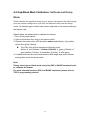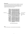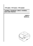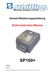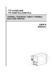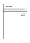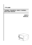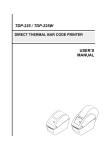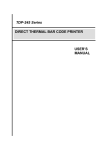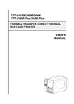
1
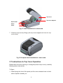
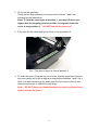
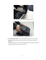
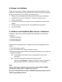
Gesamt-Bedienungsanleitung Entire Instruction Manual SP100+ Deutsch English k:\bedienungsanltg\signiertechnik\ba-erstellung\sp100+\sp100+_gesamt-bedienungsanleitung_de_gb.doc Gesamt-Bedienungsanleitung SP100+ Entire Instruction Manual SP100+ Revision / revision Datum Version date version Kapitel chapter Grund reason Verantwortlich responsible 27.03.2014 Alles / all Neuerstellung / new edition J. Schnell 1.0 Diese Gesamt-Bedienungsanleitung wurde nach bestem Wissen von uns erstellt. Sollten Sie trotzdem Fehler oder Unklarheiten feststellen, bitten wir Sie, uns dies mitzuteilen. Des Weiteren sind wir für Hinweise und Anregungen dankbar. Bitte wenden Sie sich an: This entire instruction manual has been generated to the best of our knowledge. However, in case you should find any incorrect or unclear passages, please inform us accordingly. We will be grateful for any hints and suggestions. Please contact: Schilling Marking Systems GmbH In Grubenäcker 1 D-78532 Tuttlingen Tel: Tel.:07461–9472–0 Fax: 07461-9472–28 http://www.schilling-marking.de e-mail: [email protected] Der Inhalt und die Dokumentation ist Eigentum der Firma Schilling Marking Systems GmbH. Sie darf weder als Fotokopie, Tonaufnahme, Video, Druck oder Mikrofilm in irgendeiner Form ohne Genehmigung der Unternehmensleitung verbreitet oder vervielfältigt werden. Dies gilt insbesondere auch für die Verbreitung der Daten in elektronischer Form oder als Datenträger. Für Schäden, die dem Unternehmen durch Missachtung entstehen, behält sich dieses alle Rechte vor. The content of this document is owned by Schilling Marking Systems GmbH. It must not be distributed or duplicated as photocopy, sound recording, video, print or microfilm in any form without the approval of the management. This applies in particular to the distribution of the data in electronic form or on a data carrier. The company reserves all rights to compensation for damage to the company caused by failure to comply. Tuttlingen, 27.03.2014 1 N I SO 9 0 0 ++49 (0)7461 9472-20 IFICATI RT N O ++49 (0)7461 9472-0 www.schilling-marking.de [email protected] DI Schilling Marking Systems GmbH Föhrenstr. 47 DE - 78532 Tuttlingen CE 0 / 11 Gesamt-Bedienungsanleitung SP100+ Entire Instruction Manual SP100+ Inhalt: 1.0 ANLEITUNG ZUM EINLEGEN DES KLISCHEEBANDES ...................................... 1 HOW TO INSERT THE STAMP TAPE ROLL CORRECTLY ................................... 3 2.0 ANLEITUNG FÜR DIE INSTALLATION DER BARTENDER SOFTWARE ............. 5 MANUAL FOR THE INSTALLATION OF THE BARTENDER SOFTWARE ........... 5 3.0 ANLEITUNG FÜR DIE INSTALLATION DES WINDOWS 7 DRUCKERTREIBER . 8 MANUAL FOR THE INSTALLATION OF THE WINDOWS-7 PRINTDRIVER ......... 8 4.0 ANLEITUNG FÜR DIE PAPIERRÜCKZUGUNTERDRÜCKUNG .......................... 10 INSTRUCTIONS ON HOW TO AVOID THE STAMP TAPE FROM ....................... 10 REVERSE-FEEDING ............................................................................................. 10 5.0 ANLAGEN / APPENDICES .................................................................................... 11 - SP100+ Prospekt.............................................................................................................................. 11 - SP100+ brochure ............................................................................................................................. 11 - SP100+ Benutzerhandbuch ............................................................................................................ 11 - SP100+ user‘s manual ..................................................................................................................... 11 1 N I SO 9 0 0 ++49 (0)7461 9472-20 IFICATI RT N O ++49 (0)7461 9472-0 www.schilling-marking.de [email protected] DI Schilling Marking Systems GmbH Föhrenstr. 47 DE - 78532 Tuttlingen CE 1 / 11 Gesamt-Bedienungsanleitung SP100+ Entire Instruction Manual SP100+ Anleitung zum Einlegen des Klischeebandes 1. Das Klischeeband besteht aus zwei verschiedenen Bändern: - das obere Band (glänzende Seite) Klischeeband - das untere Band (Papier) Trägerband Die glänzende Seite muss nach oben zeigen! 1. 2. Führen Sie das gesamte Band auf dem Boden des SP100+, unter der weißen Rolle und zwischen den beiden grünen Abstandshaltern nach Vorne. Bitte die Abstandshalter auf die Breite der Folie einstellen. 1 / 11 1 N I SO 9 0 0 ++49 (0)7461 9472-20 IFICATI RT N O ++49 (0)7461 9472-0 www.schilling-marking.de [email protected] DI Schilling Marking Systems GmbH Föhrenstr. 47 DE - 78532 Tuttlingen CE 1.0 Gesamt-Bedienungsanleitung SP100+ Entire Instruction Manual SP100+ 3. Führen Sie das gesamte Band über die Gummiwalze in den Schlitz vor dem Messer ein. 4. Ziehen sie nun das gesamte Band durch den Messerschlitz. Positionieren Sie die beiden grauen Führungen so dass das Material störungsfrei durchlaufen kann. Jetzt schließen Sie den Drucker vorsichtig mit beiden Händen. Mit einem leisen Klick rastet er ein. Jetzt können Sie einfach ihre Schablonen drucken. 1 N I SO 9 0 0 ++49 (0)7461 9472-20 IFICATI RT N O ++49 (0)7461 9472-0 www.schilling-marking.de [email protected] DI Schilling Marking Systems GmbH Föhrenstr. 47 DE - 78532 Tuttlingen CE 2 / 11 Gesamt-Bedienungsanleitung SP100+ Entire Instruction Manual SP100+ How to insert the stamp tape roll correctly 1. The stamp tape roll consists of two different types of tapes: - The upper tape (shiny side) is the Stamp Tape - The lower tape (paper) is a support during the transportation When you insert the roll the shiny side has be on top! 2. Feed the complete tape (both parts) along the bottom of the printer, underneath the white rod and between the two green braces. Please adjust the braces in accordance to the width of the tape. 1 N I SO 9 0 0 ++49 (0)7461 9472-20 IFICATI RT N O ++49 (0)7461 9472-0 www.schilling-marking.de [email protected] DI Schilling Marking Systems GmbH Föhrenstr. 47 DE - 78532 Tuttlingen CE 3 / 11 Gesamt-Bedienungsanleitung SP100+ Entire Instruction Manual SP100+ 3. Direct the tape (both parts) over the rubber roller and through the slot in front of the cutting knife. 4. Pull the tape through the slot. Make sure that the two grey rails are adjusted correctly to ensure an undisturbed flow. Close the printer carefully with both hands. Now you can easily print your stencils. 1 N I SO 9 0 0 ++49 (0)7461 9472-20 IFICATI RT N O ++49 (0)7461 9472-0 www.schilling-marking.de [email protected] DI Schilling Marking Systems GmbH Föhrenstr. 47 DE - 78532 Tuttlingen CE 4 / 11 Gesamt-Bedienungsanleitung SP100+ Entire Instruction Manual SP100+ 2.0 Anleitung für die Installation der BarTender Software Manual for the installation of the BarTender Software WICHTIG Sollten sie keine Installationsrechte auf ihrem PC haben, müssen sie die Software von ihrem Administrator installieren lassen. Folgend sie den Bildern zur Installation. IMPORTANT If you do not have installation rights on your PC, you will have to have the installation of this software done by your administrator. Follow the instruction on the pictures for installation. 1 N I SO 9 0 0 ++49 (0)7461 9472-20 IFICATI RT N O ++49 (0)7461 9472-0 www.schilling-marking.de [email protected] DI Schilling Marking Systems GmbH Föhrenstr. 47 DE - 78532 Tuttlingen CE 5 / 11 Gesamt-Bedienungsanleitung SP100+ Entire Instruction Manual SP100+ Starten der Software: Starting the Software: 1 N I SO 9 0 0 ++49 (0)7461 9472-20 IFICATI RT N O ++49 (0)7461 9472-0 www.schilling-marking.de [email protected] DI Schilling Marking Systems GmbH Föhrenstr. 47 DE - 78532 Tuttlingen CE 6 / 11 Gesamt-Bedienungsanleitung SP100+ Entire Instruction Manual SP100+ Änderung der Sprache: Change the language: 1 N I SO 9 0 0 ++49 (0)7461 9472-20 IFICATI RT N O ++49 (0)7461 9472-0 www.schilling-marking.de [email protected] DI Schilling Marking Systems GmbH Föhrenstr. 47 DE - 78532 Tuttlingen CE 7 / 11 Gesamt-Bedienungsanleitung SP100+ Entire Instruction Manual SP100+ 3.0 Anleitung für die Installation des Windows 7 Druckertreiber Manual for the installation of the Windows-7 printer driver WICHTIG Sollten sie keine Installationsrechte auf ihrem PC haben, müssen sie die Software von ihrem Administrator installieren lassen. Folgend sie den Bildern zur Installation. IMPORTANT If you do not have installation rights on your PC, you will have to have the installation of this software done by your administrator. Follow the instruction on the pictures for installation. (Von der CD / From the CD) 1 N I SO 9 0 0 ++49 (0)7461 9472-20 IFICATI RT N O ++49 (0)7461 9472-0 www.schilling-marking.de [email protected] DI Schilling Marking Systems GmbH Föhrenstr. 47 DE - 78532 Tuttlingen CE 8 / 11 Gesamt-Bedienungsanleitung SP100+ Entire Instruction Manual SP100+ Öffnen des Druckers im Windows-System: Open the printer driver in you windows system (printer settings): Änderung der Papiergröße: Änderung der gesamten Etiketteneinstellung: Change the paper dimensions: Change all the tape formats: 1 N I SO 9 0 0 ++49 (0)7461 9472-20 IFICATI RT N O ++49 (0)7461 9472-0 www.schilling-marking.de [email protected] DI Schilling Marking Systems GmbH Föhrenstr. 47 DE - 78532 Tuttlingen CE 9 / 11 Gesamt-Bedienungsanleitung SP100+ Entire Instruction Manual SP100+ 4.0 Anleitung für die Papierrückzugunterdrückung Instructions on how to avoid the stamp tape from reverse-feeding Einstellungen in der BarTender-Software unter „Datei“ -> Druckeinstellungen Open BarTender Software and go to “File” -> Printer Settings 1 N I SO 9 0 0 ++49 (0)7461 9472-20 IFICATI RT N O ++49 (0)7461 9472-0 www.schilling-marking.de [email protected] DI Schilling Marking Systems GmbH Föhrenstr. 47 DE - 78532 Tuttlingen CE 10 / 11 Gesamt-Bedienungsanleitung SP100+ Entire Instruction Manual SP100+ Alle Fenster mit OK beenden. Confirm all windows with OK. Anlagen / Appendices - SP100+ - SP100+ - SP100+ - SP100+ Prospekt brochure Benutzerhandbuch user‘s manual 11 / 11 1 N I SO 9 0 0 ++49 (0)7461 9472-20 IFICATI RT N O ++49 (0)7461 9472-0 www.schilling-marking.de [email protected] DI Schilling Marking Systems GmbH Föhrenstr. 47 DE - 78532 Tuttlingen CE 5.0 Printer SP100+ Marking Systems GmbH The easy way to create short-life stencils for electrolytic marking yourself Widths: 95 + 71mm Length: 20m / role - Up to 50 markings per stencil - Serial numbering - Logos, icons, barcodes, data matrix codes, graphics ® - Create jobs directly with Windows or optional by print programme - Use all fonts available on PC - Universal operation possibilities - Quick, easy and individual production of stencils Only by Schilling Marking Systems! P.t.o. for the printer K:\Prospekte\Signiertechnik\Prospekt-Erstellung\SP-100 without prices_GB.cdr Schilling Marking Systems GmbH In Grubenäcker 1 DE - 78532 Tuttlingen Technical modifications reserved Edition: 02/12 +49 (0)7461 9472-0 +49 (0)7461 9472-20 www.schilling-marking.de [email protected] Printer SP100+ Marking Systems GmbH High performance industrial thermotransfer printer for stamp tapes Stamp Tapes: 22.4100.13 95mm x 20m 22.4100.14 71mm x 20m Technical Specifications: - Printing speed: Variable 38, 50 or 75 mm/s - Resolution: 300 DPI (12 dots/mm) - Label Software inclusive (15 languages) - Graphic import: bmp, pcx, jpg - Vertical and horizontal alyout (Zoom function) - Fonts: 5 alphanumerical font types - Barcodes: Code 39, Code 93, Code 128 UCC, Code 128 (Subsets A, B u. C), Codabar, Interleave 2 of 5, EAN-8, EAN-13, UPC-A, UPC-E, EAN and UPC ® - Printer driver for Windows 3.XX/95/98/NT4.0/XP - Stamp tapes: widths 95mm and 71mm x length 20m - Variable colour prints with: Colour tapes: 5 colours, 110mm x 300m Polyester roles: 8 colours, 100mm x 40m - Memory: IBM Flash, 2MB RAM - Integrated tape cutter - 3 switches (tape recognition) - Interfaces: Parallel/RS232 K:\Prospekte\Signiertechnik\Prospekt-Erstellung\SP-100 without prices_GB.cdr Schilling Marking Systems GmbH In Grubenäcker 1 DE - 78532 Tuttlingen Polyester Roles: 22.4100.00 100mm x 40m 22.4100.02 100mm x 40m 22.4100.03 100mm x 40m 22.4100.04 100mm x 40m 22.4100.05 100mm x 40m 22.4100.06 100mm x 40m 22.4100.08 100mm x 40m 22.4100.09 100mm x 40m 22.4075.08 75mm x 40m Clear Red Orange Yellow Green Blue Platin White Platin Farbbänder: 22.4110.00 22.4110.02 22.4110.05 22.4110.06 22.4110.09 Black Red Green Blue White 110mm x 300m 110mm x 300m 110mm x 300m 110mm x 300m 110mm x 300m Technical modifications reserved Edition: 02/12 +49 (0)7461 9472-0 Prices on request +49 (0)7461 9472-20 www.schilling-marking.de [email protected] TTP-245 Series/343 Series THERMAL TRANSFER / DIRECT THERMAL BAR CODE PRINTER USER’S MANUAL Contents COPYRIGHT DECLARATION ...............................................................................1 COMPLIANCES ................................................................................................1 1. Introduction ...........................................................................................1 2. Getting Started......................................................................................1 2.1 Unpacking and Inspection ...............................................................1 2.2 Equipment Checklist .......................................................................1 2.3 Printer Parts ....................................................................................3 3. Setup ....................................................................................................4 3.1 Setting Up the Printer ......................................................................4 3.2 Loading the Ribbon .........................................................................4 3.3 Loading Label Stock........................................................................6 3.4 External Label Roll Mount Installation (Option) ...............................8 3.5 Peel-off Module Installation (Option) .............................................10 3.5.1 Loading the Paper in Peel-off Mode .......................................13 3.6 Cutter Module Installation (Option)................................................15 3.6.1 Loading Label in Cutter Mode.................................................17 3.7 Instructions to Top Cover Operation .............................................18 4. Power on Utilities ................................................................................21 4.1 Ribbon and Gap/Black Mark Sensor Calibration ...........................21 4.2 Gap/Black Mark Calibration, Self-test and Dump Mode ................23 4.3 Printer Initialization ........................................................................26 4.4 Set Black Mark Sensor as Media Sensor and Calibrate the Black Mark Sensor........................................................................................27 4.5 Set Gap Sensor as Media Sensor and Calibrate the Gap Sensor.27 4.6 Skip AUTO.BAS ............................................................................27 5. Maintenance .......................................................................................29 5.1 Cleaning ........................................................................................29 6. Troubleshooting ..................................................................................30 6.1 LED Status ....................................................................................30 6.2 Print Quality...................................................................................31 7. LED and Button Operation..................................................................32 7.1 LED ...............................................................................................32 7.2 Button Operation ...........................................................................32 i Copyright Declaration Information in this subject to change without notice and does not represent a commitment on the part of TSC Auto ID Technology Co., Ltd.. No part of this manual may be reproduced or transmitted in any form by any means, for any purpose other than the purchaser’s personal use, without the expressed written permission of TSC Auto ID Technology Co., Ltd.. The TrueType font engine is developed from the “FreeType Project" by David Turner, Robert Wilhelm, and Werner Lemberg. All other products referred on this document are the trademark or the registered trademark of each belonged companies. Compliances CE Class B: EN55022: 1998+A1: 2000+A2: 2003 EN55024: 1998+A1: 2001+A2: 2003 IEC 61000-4 Series EN61000-3-2: 2006 & EN61000-3-3: 1995+A1: 2001 FCC Part 15, Class B UL, CUL C-Tick: CFR 47, Part 15/CISPR 22 3rd Edition: 1997, Class B ANSI C63.4: 2003 Canadian ICES-003 TÜV-GS: EN60950: 2000 Wichtige Sicherheits-Hinweise 1. Bitte lesen Sie Diese Hinweis sorgfältig durch 2. Heben Sie diese Anleitung fűr den späteren Gebrauch auf. 3. Vor jedem Reinigen ist das Gerät vom Stromentz zu trennen. Verwenden Sie Keine Flűssig-oder Aerosolreiniger. Am besten eignet sich ein angefeuchtetes Tuch zur Reinigung. 4. Die Netzanschlußsteckdose soll nahe dem Gerät angebraucht und leicht zugänglich sein. 5. Das Gerät ist vor Feuchtigkeit zu schűtzen. 6. Bei der Aufstellung des Gerätes ist auf sicheren Stand zu achten. Ein Kippen oder Fallen könnte Beschädigungen hervorrufen. 7. Beáchten Sie beim Anschluß an das stromnetz die Anschlußwerte. 1 8. Dieses das Gerät kann bis zu einer Außentemperatur von maximal 40℃ betieben werden. 2 1. Introduction Thank you for purchasing the TSC TTP-245 series/343 series Thermal Transfer and Direct Thermal Bar Code Printers. Although the printer takes only a small amount of space, it delivers reliable, superior performance. This printer provides both thermal transfer and direct thermal printing at user selectable speed of: 2.0, 3.0, 4.0 or 5.0 ips, for TTP-245 series; 2.0 or 3.0 ips for TTP-343 series. It accepts roll feed, die-cut, and fan-fold labels for both thermal transfer and direct thermal printing. All common bar codes formats are available. Fonts and bar codes can be printed in 4 directions, 8 different alphanumeric bitmap fonts and a build-in true type font capability. You will enjoy high throughput for printing labels with this printer. 2. Getting Started 2.1 Unpacking and Inspection This printer has been specially packaged to withstand damage during shipping. Please carefully inspect the packaging and printer upon receiving the bar code printer. Please retain the packaging materials in case you need to reship the printer. 2.2 Equipment Checklist One printer unit One Windows labeling software/driver CD disk One sample ribbon roll One sample label roll One label spindle (1 inch diameter core) Two label spindle fixed tabs Two 1.5” core adapter One paper core for ribbon rewind spindle Two ribbon supply/rewind spindles One Centronics interface cable One auto switching power supply One power cord One quick start guide If any parts are missing, please contact the Customer Service Department of your purchased reseller or distributor. Options External label roll mount Label spindle (3-inch diameter core) Programmable keyboard (KU-007 Plus) Stand-alone LCD keyboard (KP-200) Automatic cutter module Peel off module Internal Ethernet print server External 802.11b/g wireless print server 2 2.3 Printer Parts Clear Window Ribbon Access Cover LED Indicator Feed Button Printer Top Cover Top Cover Open Lever Fig. 1 Top front view 1. USB Interface 2. Centronics Interface 3. RS-232C DB-9 Interface 4. Power Jack 5. Power Switch 6 6. 1 2 3 4 5 Fig. 2 Rear view 3 Rear Paper Guide 3. Setup 3.1 Setting Up the Printer 1. Place the printer on a flat, secure surface. 2. Make sure the power switch is off. 3. Connect the printer to the computer with the Centronics or USB cable. 4. Plug the power cord into the power supply connector at the rear of the printer, and then plug the power cord into a properly grounded receptacle. Plug USB Power Switch Power Cable Centronics RS-232C Power Supply Fig. 3 Attach power supply to printer 3.2 Loading the Ribbon The printer will detect if the ribbon is installed after turning on power on and it will set printing mode to thermal transfer or direct thermal printing mode automatically. If printer does not detect the ribbon, the ribbon take up motor will be turned off. 4 Make sure the printer top cover is engaged properly at both sides prior to powering up the printer. Please follow the steps below to install the ribbon into printer. 1. Push down on the ribbon access window to unlatch and open the cover. 2. Place a paper core onto the ribbon rewind spindle. 3. Mount the ribbon rewind paper core on the front hubs. 4. Install a ribbon on the ribbon supply spindle. 5. Mount the ribbon supply spindle on the rear hubs. 6. Thread the ribbon leading tape downward pass the print head. 7. Attach the ribbon leader to the ribbon rewind paper core. 8. Rotate the ribbon rewind paper core until the ribbon leader is thoroughly, firmly encompassed by the black section of the ribbon. 9. Close the ribbon access window. Paper Core Ribbon Access Cover Ribbon Spindle Back Hub Front Hub Fig. 4 Ribbon installation (I) 5 Ribbon supply spindle Ribbon Lead Tape Rear Hub Ribbon Rewind Spindle with Paper Core Fig. 5 Ribbon installation (II) 3.3 Loading Label Stock 1. Insert a 1” label spindle into a paper roll ( * If your paper core is 1 inch, remove the 1.5” core adapter from the fixed tab. If label width is 4 inch wide, two fixing tabs are not required. ). 1.5” Core Paper Roll Adapter* Fixed Tab Printing Side Face Up 1” Label Spindle Fig. 6 Label roll installation (I) 2. Open the printer’s top cover by releasing the green top cover open levers 6 located on each side of the printer and lifting the top cover. A top cover support at the rear of the printer will hold the printer top cover open. Lower Cover 3. 4. 5. 6. Fig. 7 Pull the lever to open the cover Place a roll of paper onto the center of the paper roll mount. Feed the paper, printing side face up, through the Teflon bar and the paper guide and pass over the platen. Adjust the green center-biased paper guides to slightly touch the edges of the label backing. To close the printer top cover, lift the cover to the ultimate open angle then use both hands to close the cover gently. Close the printer top cover slowly and make sure the cover latches securely. Note: 1. Make sure hands are not placed between printer top cover and lower cover when close the top cover. 2. Do not free fall the top cover. 3. Failure to securely close and lock the cover will result in poor print quality. 7 Printer Top Cover Top Cover Support Paper Roll Mount Teflon Bar Paper Guide Top Cover Open Lever Fig. 8 Label installation (II) 3.4 External Label Roll Mount Installation (Option) 1. Attach an external paper roll mount on the bottom of the printer. Fig. 9 Attach the external roll mount to the printer 1. Open the printer top cover by releasing the top cover open levers. The top cover support will hold the printer top cover. 2. Install a roll of paper on the external paper roll mount. 3. Feed the paper to the external paper feed opening through the rear paper guide. 8 External Paper Roll Mount External Paper Feed Opening Fig. 10 External roll mount label installation (I) 4. Feed the paper, printing side face up, through the paper guide and pass over the platen. 5. Adjust the paper guides to fit the paper width. 6. Close the printer top cover by lifting the top cover to the maximum opening angle then push down the top cover gently. Rear Paper Guide Top Cover Support Paper Guide Platen Fig. 11 External roll mount label installation (II) 9 3.5 Peel-off Module Installation (Option) 1. Open the top cover and remove the front panel from the printer. Front Panel Fig. 12 Remove the front panel 2. Open the top cover and hold it and push down and push backward the top cover support then push backward the top cover. 3. Use a screwdriver to screw off 6 screws on the lower inner cover. Top Cover Top Cover Support Screws Flute Lower Inner Cover Screws Lower Cover Fig. 13 Remove 6 screws from lower inner cover 4. Upside down the printer. Remove two screws at the hinge and remove one 10 screw at memory card cover. 5. Hold the lower cover to lift up the top cover open levers to separate the lower inner cover and the lower cover. 6. Arrange the cable through the bezel. Connect the peel-off panel cable to the 5-pin socket on printer PCB. PCB 5-pin Socket Peel-off panel Cable Peel-off panel Tenon Fig. 14 Connect peel-off sensor cable to main board Bezel Mortise Fig. 15 Peel-off sensor cable installation 11 7. Insert the peel-off tenons into the lower inner cover mortises until tenons snap into places. Lower Inner Cover Roller Lower Cover Tenon Mortise Fig. 16 Peel-off panel installation (I) 8. Arrange the lower inner cover back to the lower cover. Peel-off panel Roller Fig. 17 Peel-off panel installation (II) 9. Lift up the peel-off panel to the lower cover to close it. 10. Use a screwdriver to screw down whole screws on the lower inner cover and the lower cover. 11. Close the top cover by arranging the top cover support back to the flute and push it forward then close the top cover slowly. 12 3.5.1 Loading the Paper in Peel-off Mode Note: Both thermal paper and plain paper apply for peel-off function but neither PVC nor vynle work at peel-off function. 1. Insert a 1” label spindle into a paper roll. 2. Open the printer top cover by pulling the top cover open levers. The top cover support will hold the printer top cover. Peel-off panel Backing paper Top Cover Open Lever Opening Fig. 18 Open the top cover 3. Install the paper roll on the paper roll mount. 4. Open the peel-off panel by pulling it out. Peel-off panel 13 Fig. 19 Open the peel-off panel 5. Feed the paper, printing side facing up, through the paper guide and pass over the platen. 6. Lead the paper through the backing paper opening, beneath the roller, and tear off one piece of the label. 7. Adjust the paper guide by removing left or right to fit the paper width. Top Cover Top Cover Support Roller Peel-off panel Fig. 20 Lead the paper through the backing paper opening, beneath the roller 8. Push the peel-off panel back to the printer. 9. Close the top cover by lifting up the top cover support and close the top cover slowly. Note: Pull the label outward tightly after closing the top cover. 14 Fig. 21 Complete label installation for peel-off mode 3.6 Cutter Module Installation (Option) 1. Pull the top cover open levers to open the top cover. 2. Remove the front panel from the lower cover. Lower Cover Fig. 22 Pull the lever to open the cover 3. Open the top cover and hold it and push down and push backward the top cover support then push backward the top cover. 4. Use a screwdriver to screw off 6 screws on the lower inner cover. Top Cover Top Cover Support Screws Flute Front Panel Screws Lower Inner Cover Lower Cover 15 Fig. 23 Remove 6 screws from lower inner cover 5. Place the printer upside down and unscrew the two screws of the hinge holder on the lower cover. Unscrew the screw of the memory card cover. 6. Use both thumbs to hold the lower cover and index fingers to lift up the top cover open levers to separate the lower inner cover and the lower cover. 7. Arrange the cable through the bezel. Connect the cutter module cable to the 4-pin socket on printer PCB. PCB 4-pin Socket Cutter Cable Cutter Fig. 24 Cutter module installation Lower Inner Cover Cutter Cable Lower Cover 16 Bezel Fig. 25 Cutter module cable arrangement 8. Arrange the lower inner cover back to the lower cover. 9. Install the cutter into the niches of the printer. Cutter Niche Fig. 26 Cutter module installation 10. Use a screwdriver to screw whole screws on the lower inner cover and the lower cover. 11. Close the top cover by arranging the top cover support back to the flute and push it forward then close the top cover slowly. 3.6.1 Loading Label in Cutter Mode 1. 2. 3. 4. Insert a 1” label spindle into a paper roll. Open the printer top. Install a paper roll on the paper roll mount. Feed the paper, printing side face up, through the paper guide and pass over the platen. 5. Lead the paper through the cutter paper opening. 6. Adjust the paper guide by removing left or right to fit the paper width. 17 Top Cover Top Cover Support Paper Guide Platen Cutter Fig. 27 Label installation in cutter mode 7. Close the top cover by lifting up the top cover support and close the top cover slowly. Fig. 28 Complete label installation in cutter mode 3.7 Instructions to Top Cover Operation Please take care when opening or closing the printer’s top cover by carefully following these instructions. To Open: 1. When facing the front of the printer pull the cover release levers on both sides of printer towards you. 18 2. Lift up the top gradually. There are two stop positions for the top cover. Position 1 and 2 are indicated on the label below. Note: To hold the cover open at position 1, you must lift the cover higher than the stopping point at position 1 and gently lower the cover to stop position 1. DO NOT free fall the top cover! 3. Fully open the top cover and gently lower it to stop position 2. Fig. 1 Top cover support is fixed at position 2 4. To close the cover, lift up the top cover to the ultimate angle then close the top cover gently and it will be kept at a stop position between 1 and 2 for a while. Use both hands to gently push down the top cover to close it and make sure the cover is latched on both sides. Note: DO NOT place your hands between top cover and lower cover while close the top cover! 19 Fig. 2 Top cover is fully open and ready to close Fig. 3 Use both hands to close the top cover 5. Do not force the cover! If you are not sure if top cover is fixed at stop position, please do not push top cover to close it or the top cover will be damaged. Please open the top cover to the ultimate angle to close the top cover again. Use both hands to push top cover to close it. 20 4. Power on Utilities There are six power-on utilities to set up and test printer hardware. These utilities are activated by pressing FEED button and by turning on the printer power simultaneously. The utilities are listed as below: 1. Ribbon sensor calibration and Gap or black mark sensor calibration 2. Gap/black mark sensor calibration;Self-test and dump mode 3. 4. 5. 6. Printer initialization Set black mark sensor as media sensor and calibrate the black mark sensor Set gap sensor as media sensor and calibrate the gap sensor Skip AUTO.BAS 4.1 Ribbon and Gap/Black Mark Sensor Calibration Gap/black mark sensor sensitivity should be calibrated at the following conditions: 1. A brand new printer 2. Change label stock. 3. Printer initialization. Please follow the steps below to calibrate the ribbon and gap/black mark sensor. 1. Turn off the power switch. 2. Hold on the button then turn on the power switch. 3 Release the button when LED becomes red and blinking. (Any red will do during the 5 blinks). It will calibrate the ribbon sensor and gap/black mark sensor sensitivity. The LED color will be changed as following order: Amber red (5 blinks) amber (5 blinks) green (5 blinks) green/amber (5 blinks) red/amber (5 blinks) solid green Note: Please select gap or black mark sensor by sending GAP or BLINE command to printer prior to calibrate the sensor. For more information about GAP and BLINE command, please refer to TSPL2 programming manual. 21 22 4.2 Gap/Black Mark Calibration, Self-test and Dump Mode While calibrate the gap/black mark sensor, printer will measure the label length, print the internal configuration (self-test) on label and then enter the dump mode. To calibrate gap or black mark sensor, depends on the sensor setting in the last print job. Please follow the steps below to calibrate the sensor. 1.Turn off the power switch. 2. Hold on the button then turn on the power switch. 3. Release the button when LED becomes amber and blinking. (Any amber will do during the 5 blinks). The LED color will be changed as following order. Amber red (5 blinks) amber (5 blinks) green (5 blinks) green/amber (5 blinks) red/amber (5 blinks) solid green 4. It calibrates the sensor and measures the label length and prints internal settings then enter the dump mode. Note: Please select gap or black mark sensor by GAP or BLINE command prior to calibrate the sensor. For more information about GAP and BLINE command, please refer to TSPL2 programming manual. 23 Self-test Printer will print the printer configuration after gap/black mark sensor calibration. Self-test printout can be used to check if there is any dot damage on the heater element, printer configurations and available memory space. Print head check pattern Firmware version Firmware checksum Printed mileage (meter) Serial port configuration Country code Print speed (inch/sec) Print darkness Label size (inch) Gap distance (inch) Gap/black mark sensor sensitivity Total & available memory space Fig. 29 Self-test printout 24 Dump mode Printer will enter dump mode after printing printer configuration. In the dump mode, all characters will be printed in 2 columns as following. The left side characters are received from your system and right side data are the corresponding hexadecimal value of the characters. It allows users or engineers to verify and debug the program. ASCII Data Hex decimal data related to left column of ASCII data Fig. 30 Dump mode printout Note: Turn off / on the power to resume printer for normal printing. 25 4.3 Printer Initialization Printer initialization is used to clear DRAM and restore printer settings to defaults. The only one exception is ribbon sensitivity, which will note be restored to default. Printer initialization is activated by the following procedures. 1. Turn off the power switch. 2. Hold on the button then turn on the power switch. 3. Release the button when LED turns green after 5 amber blinks. (Any green will do during the 5 blinks). The LED color will be changed as following: Amber red (5 blinks) green/amber (5 blinks) amber (5 blinks) green (5 blinks) red/amber (5 blinks) solid green Printer configuration will be restore to defaults as below after initialization. Parameter Default setting Speed TTP-245, 127 mm/sec (5 ips) (203DPI) TTP-343, 76 mm/sec (3 ips) (300DPI) Density 8 Label Width 4.25” (108.0 mm) Label Height 2.5” (63.4 mm) Sensor Type Gap sensor Gap Setting 0.12” (3.0 mm) Print Direction 0 Reference Point 0,0 (upper left corner) Offset 0 Tear Mode On Peel off Mode Off Cutter Mode Off Serial Port Settings 9600 bps, none parity, 8 data bits, 1 stop bit Code Page 850 Country Code 001 Clear Flash Memory No Note: Always do gap/black mark sensor calibration after printer initialization. 26 4.4 Set Black Mark Sensor as Media Sensor and Calibrate the Black Mark Sensor Please follow the steps as below. 1. Turn off the power switch. 2. Hold on the button then turn on the power switch. 3. Release the button when LED turns green/amber after 5 green blinks. (Any green/amber will do during the 5 blinks). The LED color will be changed as following: Amber red (5 blinks) amber (5 blinks) green (5 blinks) green/amber (5 blinks) red/amber (5 blinks) solid green 4.5 Set Gap Sensor as Media Sensor and Calibrate the Gap Sensor Please follow the steps as below. 1. Turn off the power switch. 2. Hold on the button then turn on the power switch. 3. Release the button when LED turns red/amber after 5 green/amber blinks. (Any red/amber will do during the 5 blinks). The LED color will be changed as following: Amber red (5 blinks) amber (5 blinks) green (5 blinks) green/amber (5 blinks) red/amber (5 blinks) solid green 4.6 Skip AUTO.BAS TSPL2 programming language allows user to download an auto execution file to flash memory. Printer will run the AUTO.BAS program immediately when turning on printer power. The AUTO.BAS program can be interrupted without running the program by the power-on utility. Please follow the procedures below to skip an AUTO.BAS program. 27 1. Turn off printer power. 2. Press the FEED button and then turn on power. 3. Release the FEED button when LED becomes solid green. The LED color will be changed as following: Amber red (5 blinks) amber (5 blinks) green (5 blinks) green/amber (5 blinks) red/amber (5 blinks) solid green 4. Printer will be interrupted to run the AUTO.BAS program. 28 5. Maintenance 5.1 Cleaning Use one or more of the following supplies that meets your needs: Cotton swab Lint-free cloth Vacuum 100% ethanol The cleaning process is described as following Printer Part Method Printer Head 1. Always turns off the printer before cleaning the print head. 2. Allow the print head to cool for a minimum of one minute. 3. Use a cotton swab and 100% ethanol to clean the print head surface. Platen Roller 1. Turn the power off. 2. Rotate the platen roller and wipe it thoroughly with 100% ethanol and a cotton swab, or lint-free cloth. Exterior Wipe it with water-dampened cloth. Interior Brush or air blow. Note: Do not touch printer head by hand. If you touch it careless, please use ethanol to clean it. It’s industry alcohol. Please do not use regular alcohol, which may damage the printer head. You may have to clean the supply sensors more often if you frequently receive supply error messages. 29 6. Troubleshooting This section lists the common problems that according to the LED status and other problems you may encounter when operating the printer. Also, it provides solutions. 6.1 LED Status LED Status / Color Printer Status Solution Number Off off 1 Solid Green on 2 Green with blinking Pause 3 Red with blinking Stopped 4 1. No power. Turn on the power switch. Check if the green LED is lit on power supply. If it is not lit on, power supply is broken. Check both power connection from the power cord to the power supply and from the power supply to the printer power jack. 2. The printer is on and ready to use. No action necessary. 3. The printer is paused. Press the feed button to resume printing. 4. The out of label or ribbon or the printer setting is not correct Out of label or ribbon Load a roll of label and follow the instructions in Loading the Paper then press the feed button to resume printing. Load a roll of ribbon and follow the instructions in Loading the Ribbon then press the feed button to resume printing. Printer setting is not correct Initialize the printer by following the instructions in “Power on Utility”. 30 6.2 Print Quality Continuous feeding labels The printer setting may go wrong. Please do the Initialization and Gap/Black Mark Calibration. No print on the label Is the label or ribbon loaded correctly? Follow the instructions in Loading the Paper or Loading the Ribbon. Does the ribbon run out? Follow the instructions in Loading the Ribbon. Poor print quality Top cover is not closed properly. Close the top cover completely and make sure the right side and left side levers are latched to top cover properly. Clean the thermal print head. Adjust the print density setting. Ribbon and paper media are not compatible. 31 7. LED and Button Operation 7.1 LED LED Color Description Green/ Solid This illuminates that the power is on and the device is ready to use. Green/ Flash This illuminates that the system is downloading data from PC to memory and the printer is paused. Amber This illuminates that the system is clearing data from printer. Red / Solid This illuminates printer head open, cutter error. Red / Flash This illuminates a printing error, such as paper empty, paper jam, ribbon empty, or memory error etc. 7.2 Button Operation Feed Pause Press the button when the LED is green. It feeds the label to the beginning of the next label. Press the feed button during printing The printing job is suspended. 32 Ribbon Sensor and 1. Turn off the power switch. Gap/Black Mark 2. Hold on the button then turn on the power switch. Sensor Calibration 3 Release the button when LED becomes red and blinking. (Any red will do during the 5 blinks). It will calibrate the ribbon sensor and gap/black mark sensor sensitivity. The LED color will be changed as following order: Amber red (5 blinks) amber (5 blinks) green (5 blinks) green/amber (5 blinks) red/amber (5 blinks) solid green Note: Please select gap or black mark sensor by GAP or BLINE command prior to calibrate the sensor. For more information about GAP and BLINE command, please refer to TSPL2 programming manual. Gap/Black Mark 1.Turn off the power switch. Sensor Calibratio, 2. Hold on the button then turn on the power switch. 3. Release the button when LED becomes amber and Label Length blinking. (Any amber will do during the 5 blinks). Measurement, The LED color will be changed as following order. Self Test and enter Amber red (5 blinks) amber (5 blinks) Dump Mode green (5 blinks) green/amber (5 blinks) red/amber (5 blinks) solid green It calibrates the sensor and measures the label length and prints internal settings then enter the dump mode. Note: Please select gap or black mark sensor by GAP or BLINE command prior to calibrate the sensor. For more information about GAP and BLINE command, please refer to TSPL2 programming manual. 33 Printer Initialization 1. Turn off the power switch. 2. Hold on the button then turn on the power switch. 3. Release the button when LED turns green after 5 amber blinks. (Any green will do during the 5 blinks). The LED color will be changed as following: Amber red (5 blinks) amber (5 blinks) (5 blinks) green/amber (5 blinks) blinks) solid green green red/amber (5 Note: Always do gap/black mark sensor calibration after printer initialization. Set Black Mark 1. Turn off the power switch. Sensor as Media 2. Hold on the button then turn on the power switch. 3. Release the button when LED turns green/amber after 5 Sensor and Calibrate the Black green blinks. (Any green/amber will do during the 5 blinks). The LED color will be changed as following: Mark Sensor Amber red (5 blinks) amber (5 blinks) green (5 blinks) (5 blinks) green/amber (5 blinks) solid green red/amber Set Gap Sensor as 1. Turn off the power switch. Media Sensor and 2. Hold on the button then turn on the power switch. Calibrate the Gap 3. Release the button when LED turns red/amber after 5 green/amber blinks. (Any red/amber will do during the 5 Sensor blinks). The LED color will be changed as following: Amber red (5 blinks) amber (5 blinks) green (5 blinks) green/amber (5 blinks) blinks) solid green 34 red/amber (5 Skip AUTO.BAS 1. Turn off printer power. 2. Press the FEED button and then turn on power. 3. Release the FEED button when LED becomes solid green. The LED color will be changed as following: Amber red (5 blinks) amber (5 blinks) green (5 blinks) green/amber (5 blinks) red/amber (5 blinks) solid green 4. Printer will be interrupted to run the AUTO.BAS program. 35 TSC Auto ID Technology Co., Ltd. Headquarters / Factory No. 35, Sec. 2, Ligong 1st Rd., Wujie Town , I-Lan County, Taiwan 268, R.O.C. TEL: +886-3-990-6677 FAX: +886-3-990-5577 Web site: www.tscprinters.com E-mail: [email protected] [email protected] 36 Taipei Office 11F, No. 205, Sec. 3, Beishin Rd., Shindian City, Taipei 231, Taiwan, R.O.C.Taiwan 268, R.O.C. TEL: +886-2-8913-1308 FAX: +886-2-8913-1808