1
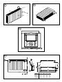
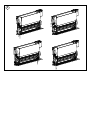
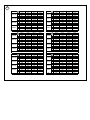
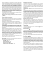
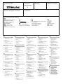
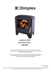
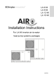
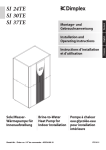
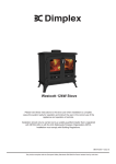
Dimplex SmartRad Fan Convector
Model: SRX80, SRX120, SRX140 & SRX180
UK
DE
FR
NL
08/51126/0
Issue 2
The product complies with the European Safety Standards EN60335-1 and the European Standard Electromagnetic Compatibility (EMC) EN55014, EN60555-2
and EN60555-3. These cover the essential requirements of EEC Directives 2006/95/EC and 2004/108/EC
2
1
3
4
Model
SRX80
SRX120
SRX140
SRX180
A
503
670
740
911
B
324
492
562
732
C
396
564
634
804
D
386
564
624
794
All dimesnsions in mm
5
Pipes1
SCALE 0.300
6
3
SRX180 2
1
3
SRX140 2
1
3
SRX120 2
1
3
SRX80 2
1
35°C
1631
1079
641
1299
838
493
1120
719
415
759
479
251
45°C
2734
1803
1069
2177
1403
823
1878
1201
693
1273
801
419
Q = 450 l/h
55°C
3844
2530
1499
3061
1968
1154
2641
1686
971
1790
1124
588
65°C
4959
3260
1929
3951
2536
1484
3408
2172
1249
2050
1448
756
3
SRX180 2
1
3
SRX140 2
1
3
SRX120 2
1
3
SRX80 2
1
35°C
1480
1020
625
1199
802
484
1044
691
408
719
465
249
45°C
2502
1713
1044
2024
1346
808
1760
1160
683
1210
780
416
Q = 300 l/h
55°C
3520
2406
1464
2850
1892
1133
2479
1629
957
1705
1095
582
65°C
4546
3102
1885
3682
2439
1459
3202
2100
1231
2203
1412
749
3
SRX180 2
1
3
SRX140 2
1
3
SRX120 2
1
3
SRX80 2
1
35°C
1059
820
558
900
671
442
806
591
379
587
413
237
45°C
1832
1408
948
1558
1151
749
1394
1010
641
1012
704
399
Q = 150 l/h
55°C
2648
2021
1346
2256
1651
1063
2016
1447
907
1460
1005
564
65°C
3498
2655
1750
2984
2167
1378
2668
1894
1174
1926
1309
728
3
SRX180 2
1
3
SRX140 2
1
3
SRX120 2
1
3
SRX80 2
1
35°C
852
695
506
752
591
411
689
530
357
530
387
231
45°C
1431
1167
848
1269
995
691
1164
894
599
902
655
387
Q = 100 l/h
55°C
2020
1647
1175
1798
1355
955
1557
1215
828
1190
884
534
65°C
2559
2109
1542
2263
1793
1251
2070
1606
1083
1580
1163
694
3
SRX180 2
1
3
SRX140 2
1
3
SRX120 2
1
3
SRX80 2
1
35°C
551
487
394
511
436
338
480
402
302
392
312
207
45°C
918
812
657
852
728
564
802
672
504
655
522
345
Q = 50 l/h
55°C
1284
1136
920
1193
1020
791
1124
943
707
921
734
486
65°C
1649
1460
1183
1535
1313
1019
1446
1215
912
1191
950
627
55/47°C
3925
2424
1395
2982
1828
1039
2506
1541
856
1595
956
516
65/50°C
4628
2879
1636
3492
2154
1176
2924
1770
1017
1777
1137
607
3
SRX180 2
1
3
SRX140 2
1
3
SRX120 2
1
3
SRX80 2
1
Q
35/30°C
1495
893
522
1078
631
344
870
561
331
573
358
201
45/40°C
2856
1760
1008
2172
1329
752
1826
1119
621
1165
695
375
Dimplex SmartRad
Models: SRX80, SRX120, SRX140 & SRX180
-1-
UK
THESE INSTRUCTIONS SHOULD BE READ CAREFULLY AND RETAINED FOR FUTURE REFERENCE
Important Safety Advice
DO NOT COVER OR OBSTRUCT the air inlet or outlet
grille.
IMPORTANT – Disconnect from the mains supply
before carrying out maintenance work.
THIS APPLIANCE MUST BE EARTHED
This heater must not be located immediately above
or below a fixed socket outlet or connection box.
Keep combustible materials such as drapes and
other furnishings clear from the front, sides and rear
of the heater.
DO NOT use this heater in the immediate surrounding
of a bath, a shower or a swimming pool.
DO NOT use this heater in areas where excessive
dust exists.
This appliance is not intended for use by children
or other persons without assistance or supervision
if their physical, sensory or mental capabilities
prevent them from using it safely. Children should
be supervised to ensure that they do not play with
the appliance.
The heater carries the Warning symbol
indicating that it must not be covered.
The instruction leaflet belongs to the appliance and
must be kept in a safe place. If changing owners, the
leaflet must be surrendered to the new owner.
IMPORTANT – If the mains lead of this appliance is
damaged, it must be replaced by the manufacturer
or its service agent or a similarly qualified person in
order to avoid a hazard.
Ensure proper manual handling procedures are
observed at all times.
General
Heat
Output*
(kW)
2
Dimensions
LxHxD
(mm)
Power Input
(W)
Air Flow
Rate
(m3/hr)
Sound
Level @ 1m
dB(A)
Voltage
(V)
SRX180
SRX140
SRX120
SRX80
1.8
1.4
1.2
0.8
911x500x145 740x500x145 670x500x145 503x500x145
3
50-53
56-60
43-47
26-27
2
33-35
36-40
29-32
19-20
1
23-24
24-26
20-22
16-17
3
540
410
345
228
2
300
225
190
125
1
160
120
100
60
3
47
47
47
47
2
38
38
38
38
1
27
27
27
27
~230-240
~230-240
~230-240
~230-240
* Rated Output at 45°C at medium fan setting.
The SmartRad convector is an intelligent convector designed
for use on central heating systems in homes and commercial
environments. The convector is optimised to work with the
Dimplex range of heat pumps and also works efficiently on
standard oil or gas fired central heating systems.
Some of the appliance’s features are highlighted in Fig.1.
(a) Aesthetic Front Panel
(b) Thermostat/ Fan selector Panel
(c) Metal air outlet grille
(d) 1m long cable
To ensure optimum performance consideration must be
given to the size of fan convector and the heating system
design. The following should be considered:
• These appliances have to be only used on closed
circulation, two pipe central heating systems.
• Appliances should be correctly sized to match the heat
loss requirements of the room. Kitchens, living areas etc,
should be based on the medium setting, while bedrooms
should be based on the low speed.
Installation Instructions.
Unpack the appliance.
Remove all packaging from the appliance. Remove the four
fixing screws at the bottom of the appliance as shown in
Fig. 2 to release the front cover. Put the front cover to one
side to avoid damage during installation.
Wall mounting.
Using the Fig 4, mark off and drill four holes in a suitable
solid wall. Insert the wall plugs (provided) into all the holes.
Screw in the top two screws to almost full way. Hang the
appliance on these top screws. Screw in the bottom two
screws to secure. Tighten the top screws. For drywalls,
use suitable wall plugs (not supplied) and repeat as above.
The appliance should be securely mounted to the wall to
mimimise the possibility of noise transmission.
Water connection.
The heating system should be capable of supplying hot
water to the appliance. Therefore the following should be
noted
–– The minimum pipe work should be 15mm
–– Appliances are not suitable for use on microbore pipes
–– Appliances are not suitable for use on one pipe
systems.
–– Where the appliance is fitted onto a system with other
emitters, a separate circuit for the appliances should be
considered to ensure an adequate water flow through
it.
–– Optimum performance of the appliance will require
balancing of the whole system.
When the appliance is mounted on the wall, water pipes
from the central heating system can be connected as shown
in Fig 5. The water pipes can be brought to the appliance
via the floor or from the wall. The appliance is supplied
with 15mm copper piping. If required balancing valves are
required these can be placed onto the pipework close to the
appliance. Ensure all water fittings are secure before filling
the central heating system. Fill the central heating system
and check for leaks. To aid commissioning the appliance is
fitted with a bleed valve as shown in Fig 4. Open this valve
to release any air in the system. Start the circulating pump
and bleed again if necessary.
The appliance can also take pipes from a number of other
routes, refer to Fig 5 for more details.
Maximum water supply conditions are 85°C and 10bar
(1.0MPa).
Power supply connection
Before commencing the electrical connection, it is essential
that the plumbing connections have been checked for leaks
and that the appliance is dry.
WARNING: THIS APPLIANCE MUST BE EARTHED
This heater must be used on an AC~ supply only and the
voltage marked on the heater must correspond with the
supply voltage.
The installation of this appliance should be carried out by
an electrician or competent person in strict accordance with
the current IEE Wiring Regulations and relevant Building
Regulations.
Before undertaking installation work, ensure the electricity
supply is disconnected from any relevant wiring. The
appliance is fitted with 1 meter of flexible cable 4 x 0.75mm²
for electrical connection. The cable may be used to connect
the heater to the fixed wiring of the premises through a
suitable connection box. The supply circuit to the heater
must incorporate a double pole isolating switch having a
contact separation of at least 3mm.
All wires must be connected so any movement of the
product does not cause a short circuit.
IMPORTANT: The wires in this mains lead are coloured in
accordance with the following code:
BROWN: LIVE – ‘L’
BLUE: NEUTRAL – ‘N’
BLACK: PILOT WIRE
GREEN & YELLOW: EARTH – ‘E’
Pilot Wire Connection
The BLACK control wire is designed to carry a signal
from ‘slot in’ or ‘wall mounted’ Dimplex programmers. If,
however a programmer is not being used, the pilot wire
should be isolated in accordance with the current IEE Wiring
Regulations.
IMPORTANT – DO NOT connect the BLACK pilot wire to
earth.
Care should be taken with the installation of the pilot wire(s)
as when switching to background (set back) they become
energised at 240V although only at a current of less than
100mA. In every case a suitable means of isolation must
be provided for the pilot wire and marked to indicate that
two sources of supply may be present at the heater. Where
pilot wires are installed separately from the heater final subcircuit they should be protected, double insulated and carry
their own integral earth continuity conductor.
Replace the Front Cover
When the appliance is plumbed to the central heating
system and wired to a suitable socket outlet, replace the
front cover. Ensure the two M5 fixing bolts are replaced as
shown in Fig 2. Turn on the supply to the appliance. Check
the operation of the appliance.
Operation
The controls are shown in Fig 3. Press the
activate the appliance.
button to
Manual Mode
In manual mode, any fan speed can be selected. Press the
button to switch between fan speeds to give the desired
output. Set the desired room temperature level using the
centre dial. This provides the optimum power output based
on the room temperature.
During this setting the Manual Mode LED will illuminate.
Eco Mode
Eco mode allows the appliances to take in signals from an
optional plug-in timer and/or a pilot wire control system. This
mode allows the appliance to operate at certain periods of
the day/week using a plug-in timer or allows a number of
appliances be controlled from a single control point using
the pilot wire controller. During eco mode the Eco Mode
LED will illuminate.
Red indicates that the appliance is operating at comfort,
and green indicates the appliance is operating at setback.
Note: If there appliance stops operating and the
LED is
flashing, this means that the water temperature in unsuitable
for the appliance. Check the operation of the heat source
and/or the circulation pump. See the Troubleshooting
section for more details.
Cold start up with Fan convectors and air source
heat pumps
An air source heat pump requires the buffer tank to be
above 14 degrees centigrade in order to perform a defrost
of the evaporator. If the outside weather conditions are
cold it is essential that the buffer tank must be bought up
to temperature before gradually opening up the heating
circuits. If the heating circuits are opened too soon there is a
risk that the buffer tank temperature will be depleted too low
and the heat pump will be unable to perform a defrost.
Troubleshooting
Insufficient heat output from the heat exchanger may be
caused by:
–– Airlock in the heat exchanger – Isolate from electrical
supply, remove the front cover, and bleed the appliance
as per the Water Connection section.
–– Water temperature too low – the boiler or heat pump
thermostat may need increasing.
–– Insufficient flow of the hot water circulating through
the radiators – rebalance by closing back lockshield
valves on radiators to increase water flow through the
appliance.
–– Dirty heat exchanger.
Cleaning and User Maintenance
WARNING: DISCONNECT POWER SUPPLY before
carrying out any cleaning or maintenance.
General cleaning
External appearance can be maintained by wiping
occasionally with a damp cloth; for stain removal, weak
soap solution can be applied, then wipe dry.
Internal cleaning and maintenance
From time to time it may be necessary to remove the front
from the unit so that the interior of the heater and the
heater compartment can be cleared of any dust or fluff.
To remove, unscrew the two fixing screws and withdraw
the front andgently remove dust with a soft brush and/or a
vacuum cleaner, taking care not to damage the fan or heat
exchanger.
After Sales Service
Your product is guaranteed for two year from the date of
purchase. Within this period, we undertake to repair or
exchange this product free of charge provided it has been
installed and operated in accordance with these instructions.
Should you require after sales service or should you need to
purchase any spares, please contact the retailer from whom
the appliance was purchased or contact the service number
relevant to your country on the warranty card. Please do
not return a faulty product to us in the first instance as this
may result in the loss or damage and delay in providing you
with a satisfactory service.
Please retain your receipt as proof of purchase.
Glen Dimplex Deutschland GmbH
Garantieurkunde Systemtechnik
(Warmwasser-Wärmepumpen, Heizungs-Wärmepumpen, zentrale Wohnungslüftungsgeräte und Raumklimageräte)
gültig für Deutschland
(Ausgabestand 04/2006)
Die nachstehenden Bedingungen, die Voraussetzungen und Umfang unserer Garantieleistung umschreiben, lassen die
Gewährleistungsverpflichtungen des Verkäufers aus dem Kaufvertrag mit dem Endabnehmer unberührt. Für die Geräte leisten wir Garantie
gemäß nachstehenden Bedingungen:
Wir beheben unentgeltlich nach Maßgabe der folgenden Bedingungen Mängel am Gerät, die nachweislich auf einem Material- und/oder
Herstellungsfehler beruhen, wenn sie uns unverzüglich nach Feststellung und innerhalb von 24 Monaten nach Lieferung an den Erstendabnehmer
gemeldet werden. Bei gewerblichem Gebrauch innerhalb von 12 Monaten. Zeigt sich der Mangel innerhalb von 6 Monaten ab Lieferung und liegt
eine erfolgreiche Inbetriebnahme (Heizungs-Wärmepumpe und zentrale Wohnungslüftungsgeräte) durch den autorisierten SystemtechnikKundendienst vor, wird vermutet, dass es sich um einen Material- oder Herstellungsfehler handelt.
Dieses Gerät fällt nur dann unter diese Garantie, wenn es von einem Unternehmer in einem der Mitgliedstaaten der Europäischen Union gekauft
wurde, es bei Auftreten des Mangels in Deutschland betrieben wird und Garantieleistungen auch in Deutschland erbracht werden können.
Die Behebung der von uns als garantiepflichtig anerkannter Mängel geschieht dadurch, dass die mangelhaften Teile unentgeltlich nach unserer
Wahl instandgesetzt oder durch einwandfreie Teile ersetzt werden. Durch Art oder Ort des Einsatzes des Gerätes oder schlechte Zugänglichkeit
des Gerätes bedingte außergewöhnliche Kosten der Mängelbeseitigung werden nicht übernommen. Der freie Gerätezugang muß durch den
Endabnehmer gestellt werden. Ausgebaute Teile, die wir zurücknehmen, gehen in unser Eigentum über. Die Garantiezeit für Nachbesserungen und
Ersatzteile endet mit dem Ablauf der ursprünglichen Garantiezeit für das Gerät. Die Garantie erstreckt sich nicht auf leicht zerbrechliche Teile, die
den Wert oder die Gebrauchstauglichkeit des Gerätes nur unwesentlich beeinträchtigen. Es ist jeweils der Original-Kaufbeleg mit Kauf- und/oder
Lieferdatum vorzulegen.
Eine Garantieleistung entfällt, wenn vom Endabnehmer oder einem Dritten die entsprechenden VDE-Vorschriften, die Bestimmungen der örtlichen
Versorgungsunternehmen oder unsere Montage- und Gebrauchsanweisung sowie die in den Projektierungsunterlagen enthaltenen Hinweise
oder Einbindungsschemen nicht beachtet worden sind oder wenn unser funktionsnotwendiges Zubehör nicht eingesetzt wurde. Durch etwa
seitens des Endabnehmers oder Dritter unsachgemäß vorgenommenen Änderungen und Arbeiten, wird die Haftung für die daraus entstehenden
Folgen aufgehoben. Die Garantie erstreckt sich auf das Gerät und vom Lieferer bezogene Teile. Nicht vom Lieferer bezogene Teile und Geräte-/
Anlagenmängel die auf nicht vom Lieferer bezogene Teile zurückzuführen sind fallen nicht unter den Garantieanspruch.
Sofern der Mangel nicht beseitigt werden kann, oder die Nachbesserung von uns abgelehnt oder unzumutbar verzögert wird, wird der Hersteller
entweder kostenfreien Ersatz liefern oder den Minderwert vergüten. Im Falle einer Ersatzlieferung, behalten wir uns die Geltendmachung einer
angemessenen Nutzunganrechnung, für die bisherigen Nutzungszeit, vor. Weitergehende oder andere Ansprüche, insbesondere solche auf
Ersatz außerhalb des Gerätes entstandener Schäden sind soweit eine Haftung nicht zwingend gesetzlich angeordnet ist ausgeschlossen. Bei
einer Haftung nach § 478 BGB wird die Haftung des Lieferers auf die Servicepauschalen des Lieferers als Höchstbetrag beschränkt.
Eine Verlängerung der Garantie auf 36 Monate für Heizungs-Wärmepumpe und zentrale Wohnungslüftungsgeräte ab Inbetriebnahmedatum,
jedoch maximal 38 Monate ab Auslieferung Werk, wird gemäß den nachfolgenden Bedingungen gewährt: Voraussetzung für die Übernahme der
verlängerten Garantie ist eine kostenpflichtige Inbetriebnahme durch den autorisierten Systemtechnik-Kundendienst mit Inbetriebnahmeprotokoll
innerhalb einer Betriebszeit (Verdichterlaufzeit) von weniger als 150 Stunden. Im Inbetriebnahmeprotokoll vermerkte Mängel sind unverzüglich zu
beseitigen. Dies ist Grundlage für die Garantie. Das Inbetriebnahmeprotokoll ist, innerhalb von einem Monat nach erfolgter Inbetriebnahme, an die
unten angegebene Adresse einzureichen, von welcher auch die Garantiezeitverlängerung bestätigt wird.
Die Inbetriebnahmepauschale beinhaltet die eigentliche Inbetriebnahme und die Fahrtkosten. Es wird keine Haftung für die ordnungsgemäße
Planung, Dimensionierung und Ausführung der Gesamtanlage übernommen. Die Behebung von Anlagenmängeln und Wartezeiten sind
Sonderleistungen.
Die Inbetriebnahmepauschale für alle Heizungs-Wärmepumpen von derzeit netto € 340,— und für zentrale Lüftungsanlagen
von netto € 400,—, jeweils je Gerät, wird durch den autorisierten Systemtechnik-Kundendienst dem Auftraggeber in Rechnung
gestellt. Eine Preisanpassung ist vorbehalten.
Im Kundendienstfalle wird der autorisierte Systemtechnik-Kundendienst vor Ort informiert, der für eine schnelle Abhilfe des Problems sorgt. Den
für Ihre Region zuständigen autorisierten Systemtechnik-Kundendienst erfahren Sie über die zentrale Servicehotline der Glen Dimplex Deutschland
GmbH.
UK - Warranty The warranty conditions
in the country of purchase apply to this
appliance. Information can be obtained
at any time from the retailer from whom
the appliance was purchased. For claims
under guarantee the sales receipt must be
produced and the claims must be
forwarded within the guarantee period.
The right to claim under guarantee
expires in case that the device has been
damaged, used in an inappropriate way
or that unauthorized manipulations have
been carried out.
FR- Garantie Pour cet appareil, les
garanties applicables sont celles en
vigueur dans le pays où a lieu l’achat. Votre
revendeur vous en communiquera à tout
moment les détails sur simple demande.
La revendication au droit à la garantie est
assujettie à la présentation de la preuve
d’achat et du respect du délai de garantie.
Le droit à la garantie expire lorsque
l’appareil a été endommagé, utilisé de
manière inadéquate ou que des
interventions ont été effectuées par des
tiers.
NL- Garantie Voor dit apparaat gelden
de in het kooplanf uitgegeven
garantievoorwaarden. Details deelt U Uw
dealer, waar U het apparaat heeft
gekocht, op aanvrag altijd mee. De
gebruikmaking van garantievergoedingen
vereist het overleggen van het koopbewijs
en de nakoming van de garantietermijn.
De garantieclaim vervalt, wanneer het
apparaat werd beschadigd, niet juist werd
gebruikt of onbevoegde ingrepen werden
uitgevoerd.
1. Warranty Card
2. Guarantee
Period (in Years)
3. Model(s)
4. Date of Purchase
2
5. Stamp & Signature of retailer
6. Fault/Defect
7. Contact Number & Address
DE
Glen Dimplex Deutschland Gmbh
Geschäftsbereich Dimplex
Kundendienst Systemtechnik
Am Goldenen Feld 18
95326 Kulmbach
+49 9221 709-562
Fax: +49 9221 709-565
e-mail:
IE
NL
UK
Glen Dimplex Benelux B.V. – Netherlands
www.dimplex.co.uk
Antennestraat 84
Fax.
(+44) 0845 600 5111
1322 AS Almere, Nederland
(+44) 01489 773050
E-mail: [email protected]
A division of the GDC Group Ltd.
www.glendimplex.nl
Dimpco Ltd
Airport Road
Cloghran
Co. Dublin
Republic of Ireland
01 842839
Fax. 01 842839
[email protected]
PT
UK
1.
2.
3.
4.
5.
6.
7.
Warranty Card
Guarantee Period (in Years)
Model(s)
Date of Purchase
Stamp & Signature of retailer
Fault/Defect
Contact Number & Address
1.
2.
3.
4.
5.
6.
7.
FI
Cartão de Garantia
Período de Garantia (em anos)
Modelo(s)
Data de Compra
Carimbo e Assinatura do
retalhista
Falha/Defeito
Número de Contacto e Morada
1.
2.
3.
4.
5.
6.
7.
SK
Takuukortti
Takuuaika (vuosina)
Malli(t)
Ostopäivämäärä
Myyntiliikkeen leima ja
allekirjoitus
Vika/vaurio
Yhteysnumero ja osoite
DE
1.
2.
3.
4.
5.
6.
7.
Garantiekarte
Garantiezeitraum (in Jahre)
Modell(e)
Kaufdatum
Stempel & Unterschrift des
Einzelhändlers
Fehler/Defekt
Kontakt-Tel.-Nr. & - Anschrift
FR
1.
2.
3.
4.
5.
6.
7.
Bon de garantie
Période de garantie (en années)
Modèle(s)
Date d’achat
Cachet et signature du vendeur
Anomalie/Défaut
Nom et adresse du contact
Scheda di garanzia
Periodo di garanzia (in anni)
Modello(i)
Data di acquisto
Timbro e firma del rivenditore
Guasto/difetto
Indirizzo e numero di contatto
ES
1.
2.
3.
4.
5.
6.
7.
1.
2.
3.
4.
5.
6.
7.
Tarjeta de garantía
Período de garantía (en años)
Modelo(s)
Fecha de adquisición
Sello y firma del distribuidor
Avería/Defecto
Número y dirección de contacto
PL
Garantiebewijs
Garantieperiode (in jaren)
Model(len)
Aankoopdatum
Stempel & Ondertekening
detaillist
Fout/Defect
Telefoonnummer & Adres
DK
1.
2.
3.
4.
5.
6.
7.
IT
1.
2.
3.
4.
5.
6.
7.
NL
Garantikort
Garantiperiode (i år)
Model(ler)
Købsdato
Detailhandlers stempel &
underskrift
Fejl/defekt
Kontaktnummer & -adresse
SE
1.
2.
3.
4.
5.
6.
7.
Garantikort
Garantitid (i år)
Modell(er)
Inköpsdag
Återförsäljarens stämpel och
underskrift
Fel
Telefonnummer och adress för
kontakt
NO
1.
2.
3.
4.
5.
6.
7.
Garantikort
Garantiperiode (i år)
Modell(er)
Kjøpsdato
Selgers stempel og signatur
Feil/defekt
Kontaktnummer og adresse
1.
2.
3.
4.
5.
6.
7.
Karta gwarancyjna
Okres gwarancji (w latach)
Model(e)
Data zakupu
Pieczec i podpis sprzedawcy
Usterka
Telefon i adres kontaktowy
CZ
1.
2.
3.
4.
5.
6.
7.
6.
7.
Záruční list
Záruční doba (roky)
Model(y)
Datum zakoupení
Razítko a podpis prodejce
Porucha/chyba
Kontaktní číslo a adresa
3.
4.
5.
6.
7.
1.
2.
3.
4.
5.
6.
7.
1.
2.
3.
4.
5.
6.
7.
Garancijski list
Obdobje veljavnosti
garancije (v letih)
Model(i)
Datum nakupa
Žig in podpis prodajalca
Pomanjkljivost/okvara
Kontaktna številka in naslov
1.
2.
3.
4.
5.
6.
7.
Garantijos kortele
Garantijos laikotarpis (metais)
Modelis (modeliai)
Pirkimo data
Prekybininko antspaudas ir
parašas
Gedimas / defektas
Numeris ir adresas kontaktams
3.
4.
5.
Garantiikaart
Garantiiaeg (aastates)
Mudel(id)
Ostukuupäev
Kaupluse tempel & allkiri
Viga/defekt
Kontaktnumber & aadress
Garancialevél
Garancia idotartama (években)
Modell(ek)
Vásárlás idopontja
Eladó bélyegzoje és aláírása
Hiba/Hiány megnevezése
Értesítési telefonszám és cím
Jamstvena kartica
Jamstveni period (u godinama)
Model(i)
Datum kupnje
Pecat i potpis dobavljaca
Kvar/defekt
Broj i adresa za kontakt
Κάρτα εγγύησης
Περίοδος ισχύος της
εγγύησης (έτη)
Μοντέλο(α)
Ημερομηνία αγοράς
Σφραγίδα και υπογραφή
εμπρου
Σφάλμα/Ελάττωμα
Αριθμς τηλεφώνου και
διεύθυνση επικοινωνίας
BG
1.
2.
3.
4.
5.
6.
7.
HR
1.
2.
3.
4.
5.
6.
7.
1.
2.
6.
7.
LT
HU
Garantijas talons
Garantijas periods (gadi)
Modelis(li)
Legades datums
Mazumtirgotaja zimogs un
paraksts
Bojajums/defekts
Kontakttalrunis un adrese
SI
1.
2.
GR
Zárucný list
Zárucné obdobie (v rokoch)
Model(y)
Dátum kúpy
Pecat & Podpis obchodníka
Porucha/závada
Kontaktujte císlo & adresu
EE
LV
1.
2.
3.
4.
5.
1.
2.
3.
4.
5.
6.
7.
Гаранционна карта
Гаранционен период (в
години)
Модел(и)
Дата на покупка
Печат и подпис на
търговеца
Неизправност/Дефект
Адрес и телефон за
контакт
RU
1.
2.
3.
4.
5.
6.
7.
KZ
Гарантийная карта
Срок действия гарантии(в
годах)
Модель (модели)
Дата покупки
Штамп и подпись
озничного продавца
Неисправность/дефект
Номер контактного
телефона и адрес