1
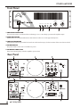
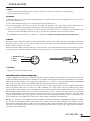
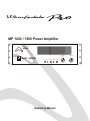
MP 1200 / 1800 Power Amplifier
CHANNEL A
ON
CHANNEL B
(BRIDGE)
4
5
3
OFF
POWER
PROTECT BRIDGE
CHA
PEAK
CHB
PEAK
7
8
2
9
1
0
10
LEVEL
Operating Manual
4
6
5
6
3
7
1
9
8
2
0
10
LEVEL
POWER AMPLIFIER
The WHARFEDALE Wireless Works was established in 1932
by Gilbert Briggs who soon established a reputation as one
of the most innovative loudspeaker engineers of his
generation. His company was at the leading edge of an
exciting new technology which was dedicated to bringing the
pleasure of music and entertainment into people's homes. As
the technology advanced Wharfedale gave many music
lovers their first taste of High Fidelity, mounting a series of live
sound demonstrations which excited the audio world and
heralded the birth of the modern hi-fi loudspeaker.
Today Wharfedale Pro takes the same uncompromising
approach to the design and manufacturing of every audio
product, using high-quality components and state-of-the-art
testing equipment to ensure consistency and high
performance. At Wharfedale we design and build all of our
products. We control all the variables, so that we don't have
to compromise our design goals.
Wharfedale Pro MP Series of Professional Power Amplifiers
are high quality amplifiers suitalbe for stage, club and studio
use. Using proven circuitry they are straightforward to use,
reliable in operation and capable of excellent performance.
Wharfedale Pro MP Series of Professional Power
Amplifiers
Over engineered power supplies with substantial
high current transformers.
Fully Protected Circuitry: Protection for thermal
Runaway; output short circuits;
DC voltages; switch on/off transients and input overload.
Cool Running: A combination of a massive extruded
aluminium heat sink and variable speed fan ensures
effective cooling.
Over Engineered Design: From the strong steel case
through the thick multi layer circuit boards to the array
of power transistors, Wharfedale have built in a healthy
safety margin.
Modern manufacturing techniques and value
engineered design.
Unpacking
All Wharfedale Pro products are
fully checked before leaving the
factory. After unpacking please
inspect contents for any physical
damage. Please retain the
shipping carton if Possible and
internal packing material in case
the unit needs to be returned. Please check as soon as
possible the unit is functioning correctly. In the event of any
damage please contact your dealer immediately so that a
written claim for damages can be made.
Wharfedale Pro Limited Warranty
Wharfedale Pro MP Series Power Amplifiers are warranted
to be clear of defects in construction, materials and
malfunction under normal operating conditions. Wharfedale
will, during the warranty, and its own discretion, undertake to
make repairs at no charge if the product has been delivered
to Wharfedale Pro by a Wharfedale Dealer. Wharfedale
exclude normal exterior wear to finish and cannot be held
1
MP 1200/1800
responsible for any system malfunction due to abuse or using
the units beyond the limits and conditions as stated within the
specified ratings. Wharfedale shall not be liable for any
consequential damages. Any implied warranties expire after
the given term.
This warranty is only valid providing:
I) Warranty applies to original purchaser only (warranty
not transferable)
II) Warranty card must be filled in fully and returned to
wharfedale Pro within 30 days from date of purchase.
Failure to do will not affect your statutory rights.
IV)Unit must be returned with original sales receipt or
other proof of purchase .
V) Unit is repaired by Wharfedale or authorised service
agent only.
These terms do not infringe your statutory rights.
POWER AMPLIFIER
PLEASE READ IMPORTANT INSTRUCTIONS
BEFORE USING THE AMPLIFIERS! SAFETY
INSTRUCTIONS
To reduce the risk of electric shock the user should not
remove the cover. All operating and safety instructions
should be fillowed. The unit should be kept clear of water,
fluids and moisture and not be operated in damp
conditions. The unit should be operated in a well ventilated
environment. The unit should be kept away from excessive
heat sources such as radiators and if racked with other
power amplifiers there should be a free air flow to vent out
the heat produced check with (dealer). The unit must only
be connected to a power supply as shown on the rear of
the unit with the IEC cable (or similar) provided with
precaution taken to make sure that the grounding (earthing)
or prolarisation is in place and not in defeat mode (ie.
earth disconnected). The power cord must be situated or
routed so as not to be walked upon or pinched or objects
placed upon it with special attention to the area where the
power cable enters the unit. the power cable should be
disconnected during prolonged non usage. The user
should not attempt to service the unit or do anything to the
unit except those things described in this manual. For
service and repair your dealer should be contacted. This
unit complies with the relevant safety regulations.
APPLICATION
The new Mp range of power amplifiers from Wharfedale is
designed to give musicians, club owners and DJ's the
performance, reliability and sound quality they require.
DESCRIPTION
The MP series consists of two models, the Mp1200,
Mp1800. These power amplifiers are designed for
standard 19" (482mm) rack mounting. They have power
supplies with substantial heavy high current transformers
threrefore each model requires rear rack support to prevent
stress on the front panel. These amplifiers are housed in
steel casing suitable for racking in professional flight cases.
OPERATING
Before switching on the power amplifier ensure that ALL
audio inputs are connected, ALL speaker cables are
securely connected, ALL volume controls on the front panel
are fully off and that the mains connections are safely and
fully off and that the mains connections are safely and
securely connected at the supply and amplifier unit.
CLASS 2 WIRING
POWER NOTICE FOR SAFETY
All british and european countries have a nominal 230v
mains power supply which in practice is between 220V
and 240V. In the USA the main power supply is
nominally 115V and in Japan 100V. This unit is factory
set to the correct voltage and this can be checked by
looking at the label on the rear panel near the power
cable. If the unit is to be used in a country other than that
it was shipped to consult your dealer. The unit is suitable
for use with mains frequencies of 50-60Hz. As there are
no user serviceable components inside the amplifier, and
high voltages are present, DO NOT remove the covers!
Be sure to make all audio connections to the amplifier
before connecting to the mains supply. Do not disconnect
the amplifier from the grounded equipment with the
mains connector still plugged into the mains supply.
Important warning! This Unit Must Be Grounded, Do not
Disconnect the Ground Connection! Any sound system
should be connected to ground at one point only. If there
is more than one connection to earth, a GROUND LOOP
can be formed, which allows mains hum to enter the
circuitry, sometimes at a high level. If hum occurs in the
system consult your dealer.
Class 2 wiring for all terminals provided the audio output
power exceeds 10W per channel under normal operating
conditions or the apparatus is intended to be installed or
interconnected in the field by a skilled person.
MP 1200/1800
2
POWER AMPLIFIER
Front Panel
CHANNEL A
ON
CHANNEL B
(BRIDGE)
4
5
3
OFF
POWER PROTECT
BRIDGE
CHA
PEAK
CHB
PEAK
4
6
8
2
0
5
1
7
8
9
1
0
10
LEVEL
4
6
2
9
1
5
3
7
2
10
LEVEL
3
1. PROTECTION INDICATOR
The pro-tection systems are activated when overheating occurs or a DC voltage Is present at the amplifier outputs.
2. PEAK INDICATORS
PEAK indicator on each channel illuminates when distortion reaches or exceeds approximately 0.1%.
3. INPUT ATTENUATORS
Separate level controls are provided for channel one and channel two input, clockwise rotation of the controls increase level.
4. POWER SWITCH
The power switch is used to turn on and off the AC power.
5. POWER ON INDICATOR
The power indicator lights up when the amplifier is powered ON.
.
Rear Panel
3
1
2
BRIDGED OUTPUT
1800W 4 OHM
FUSE
T10AL250V
N 1118 9
~
AC 220-240V 50Hz 2400W
UK
3
5
1
2
4
N 1118 9
CONFORMS TO
UL STD. 6500
®
C
US
3021177
USA
5
3 MP 1200/1800
CERTIFIED TO
CAN/CSA STD. E60065
4
POWER AMPLIFIER
1. FANS
The fans should be kept free of all obstructions and be accessible to cool fresh air when possible. It is important that the
fans be used in a dust free environment.
2.OUTPUTS
Loudspeaker outputs are on large diamete 30A binding posts or Speakon NL4 connectors. The binding posts may be used in 3
ways. In order of preference:a) Use a quality 4mm Banana plug, colour coded, into the back of the binding posts.
b) Bare wire through the hole in the post, screwed down tight. This provides a very good electrical contact which is also very
secure. Use the heaviest gauge speaker cable possible. A 4mm banana plug may be similarly clamped in this way.
c) Bare wire may be wrapped around the post and the clamp screwed down. Be sure to wind the wire CLOCKWISE so that
screwing down the clamp tightens the wrap. This gives a good electrical connection and is secure if done Properly.
The SPEAKON sockets are wired: - l+ = positive, 1- = negative. 2+ and2- are not used under normal operations.
3.INPUTS
Each input channel is electronically balanced with one female XLR connector. in accordance with IEC and AES/ANSI standards the
wiring mode is Pin 1 Ground, Pin 2 Hot and Pin 3 Cold. the 1/4" Jack socket is also wired in parallel with the XLR'S. the Tip is Hot,
the ring is Cold and the sleeve is Ground.
Balanced Operation: Either transformer balanced or with active drive. connect the input between pins 2 and 3 with pin 2 positive.
do not connect pin 1, attached the shield to connector case (classes ground). Do not connect the shield at this end to anything.
1. GROUND (shield)
2. HOT+
3. COLD-
1
2
3
4. AC INLET
Plug this AC input cord into AC outlet.
5 BRIDGED OUTPUT (MONO OPERATION)
To obtain a higher power output into a loudspeaker load the two stereo channels may be bridged to form one (Mono) channel. To
do this connect the positive speaker wire to the RED post on channel-A, and the negative speaker wire to the RED post on channel-B.
Alternatively the bridge Speakon can be used (the pin configuration is l + = positive, 1- = negative). When in this mode the BRIDGE
switch on the rear panel should be set to BRIDGE and the signal input should be wired to channel A only.
Many loudspeaker cabinest have more than one connector in order to connect extra cabinets to the same amplifier channel without
the need for splitter cables. These connectors are wired in PARALLEL. Two 16ohm speakers wired in parallel equates to 8ohm
(16/2=8). Three 16ohm speakers will give 5.3ohm(16/3=5.3). Two 8ohm speakers wired in SERIES will add up to 16ohm, three
8ohm speakers would be 24ohm and so on. To share power between two pairs or three pairs of similar speakers, they should be
wired in SERIES/PARALLEL. Two 8ohm speakers for example are wired in series giving 16ohm impedance. Two further 8ohm
speakers are wired in the same way, giving 16ohm. Each pair is then wired in paralled with the other to give a nominal 8ohm. The
power available from any amplifier into an 8ohm load is shared equally amongst the four 8ohm speakers.
Bridging two channels of an amplifier combines the outputs to obtain twice the power. A600+600 watt amplifier into 4ohm
per channel will theoretically deliver 1200 watts into an 8ohm load. Four 8ohm 300-400 watt speakers wired in
series/parallel as described above would be able to handle this output. 4ohm loudspeaker loads should only be used with
care when in the bridged mode because the true load might be below 2ohms and at high output levels the amplifier's
protection circuits could operate.
MP 1200/1800
4
POWER AMPLIFIER
Specifications
RATED OUTPUT POWER
Stereo mode , EIA: Bothe Channels Driven
8W(1%THD)
4W(1%THD)
2W(1%THD)
Bridged mono, mode
8W(1%THD)
4W(1%THD)
INPUT SENSITIVITY & IMPEDANCE:
@ rated output power,4 ohms
Unbalanced, 1/4 hone jack
Balanced , XLR
VOLTAGE GAIN
SLEW RATE:8W full swing
Stereo
Bridged mono, mode
CHANNEL SEPARATION:
SIGNAL TO NOISE(20Hz-20KHz)
DISTORTION: (SMPTE-IM)
FREQUENCY RESPONSE:
(+/-1dB) @ rated output, 4 ohms
(+/-1dB) @ rated output, 4 ohms
DAMPING FACTOR: (8 ohms, 1 KHz)
TOPOLOGY
CONNECTORS:
Input
Output
CONTROLS
Front
Real
INDICATORS
COOLING
WEIGHT
Gross Weight
Net Weight
DIMENSION(HxWxD)
MP 1200
MP 1800
260 W x 2
400 W x 2
640 W x 2
330W x 2
600 W x 2
900 W x 2
800 W
1280 W
1200 W
1800 W
0.775 V
10Kohms
20Kohm
35dB
0.775 V
10Kohms
20Kohm
35dB
> 30v/ sec
> 50v/ sec
76dB
>100dB
less then 0.01%
20Hz-20KHz
5Hz-50KHz
Greater then 300
AB
MP 1200/1800
20Hz-20KHz
5Hz-50KHz
Greater then 300
AB
,,
,,
XLR and1/4 TRS
XLR and1/4 TRS
5 way binding posts or Neutrik Speakon 5 way binding posts or Neutrik Speakon
AC switch, CH.1 and CH.2 gain knobs
Stereo/Briding mode switch
Power switch on/off mute, Short circuit, Open
Circuit, Thermal
AC switch, CH.1and CH.2 gain knobs
Stereo/Briding mode switch
Power switch on/off mute, Shortcircuit ,Open
circuit, Thermal
Continuously vasriable-speed fan
Continuously vasriable-speed fan
23Kg
21.5Kg
480x360x150(mm)
25Kg
23.5Kg
480x360x150(mm)
Specifications and design subject to shange without notice for improvements.
5
> 30v/ sec
> 50v/ sec
76dB
>100dB
less then 0.01%
POWER AMPLIFIER
BALANCED INPUT WIRING TO WHARFEDALE PRO UNIT WITH XLR CONNECTORS
BALANCED OUTPUT
INPUT to Wharfedale Pro unit
SIGNAL DIRECTION
2
1
1
Ground (earth)
2
Only connect ground if hum occurs
CABLE
3
3
,,
BALANCED INPUT WIRING TO WHARFEDALE PRO UNIT WITH 1/4 JACK to XLR CONNECTORS
INPUT to Wharfedale Pro unit
SIGNAL DIRECTION
BALANCED OUTPUT
RING
1
TIP
2
SLEEVE
Ground (earth)
CABLE
Only connect ground if hum occurs
3
,,
BALANCED INPUT WIRING TO WHARFEDALE PRO UNIT WITH STEREO 1/4 JACK to XLR CONNECTORS
SIGNAL DIRECTION
BALANCED OUTPUT
INPUT to Wharfedale Pro unit
RING
SLEEVE
TIP
RING
TIP
SLEEVE
Ground (earth)
CABLE
Only connect ground if hum occurs
,,
BALANCED INPUT WIRING TO WHARFEDALE PRO UNIT WITH XLR CONNECTORS to STEREO 1/4 JACK
BALANCED OUTPUT
INPUT to
Wharfedale Pro unit
SIGNAL DIRECTION
SLEEVE
2
TIP
1
Ground (earth)
CABLE
Only connect ground if hum occurs
3
RING
,,
UNBALANCED INPUT AND OUTPUT WIRING WITH MONO 1/4 JACK CONNECTIONS
OUTPUT
SIGNAL DIRECTION
INPUT to Wharfedale Pro unit
OUTPUT Wharfedale Pro unit
SIGNAL DIRECTION
INPUT
SLEEVE
TIP
TIP
SLEEVE
Ground (earth)
CABLE
BALANCED OUTPUT WIRING FROM WHARFEDALE PRO UNIT WITH XLR CONNECTORS TO BALANCED UNIT
OUTPUT from Wharfedale Pro unit
BALANCED INPUT
SIGNAL DIRECTION
2
1
1
Ground (earth)
3
CABLE
Only connect ground if hum occurs
3
2
A great deal of mistakes in sound
installations can be down to wrongly wired
audio connections. It is important that the
connections are correct to suit your system.
Unbalanced system
An unbalanced audio system is typically a
single conductor shielded with the centre
conductor relaying the signal and the shield
at ground.
Balanced system
Using a balanced audio system is where a
two conductor shielded cable has each of
the two centre conductors carrying the
signal but of opposite phase. This gives
each conductor an equal but inverted
potential difference from that of the ground.
It is recommend that you use balanced audo
connections if the unit before your amplifier
has a balanced output. This will eliminate
such as mains hum. For the best results
xommon grounding should be avoided. This
means not connecting the ground on both
the amplifiers input and output connectors.
Wharfedale pro advise that you connect the
ground (shield) of the input connecting
cable to the ground of the signal source
while making sure the ground (shield) is not
connected to the amplifier's input connector.
The output cable connector from the
amplifier if linking to another amplifier
(daisy chained via parallel input sockets)
should have the ground (shield) connected.
The input connector ground (shield) to the
following amplifier should not be connected.
This is the process by which the ground
(shield) is connected (tied) at the source unit
but is not connect to the destination unit. If
hum develops in some instances the ground
(shield) can be connected on the input.
Some manufacturers have units that
recommend that the input connector ground
(shield) is tied and the output disconnected.
In this instance you may need to connect the
input connector ground (shield) going to the
input of the wharfedale pro unit. If an
unbalanced system is used with XLR
connections please connect pin 3 to pin 1
(ground) of the connector. This will mean
that pin 2 transports the positive (+/hot)
signal. If pin 3 to pin 1 are not connected
this results in the negative (-/cold) input
being 'open'. This will give an audible
degradation of the signal to noise ratio. This
would relate to both the input and output
connectors and involve the cable ground
(shield) connected at both.
Please note that some manufacturers run
their units with pin 2 (-/cold) and pin 3
(+/hot). This should be looked out for and
then the wiring could be modified with
labelled cables so that connections of +/hot
go to their corresponding +/hot etc. Some
manufactures run their units with balanced
inputs and unbalanced outputs, therefore
care should be taken with the connections
when inserted into the system.
MP 1200/1800
6
Etensive Thermal Protection
All though the MP Series of amplifier feature powerful cooling fans it is possible that there will be an abnormally high temperature
rise under some circumstances. When this happens special sensors will cause the amplifier to protect itself by first disconnecting the
loudspeakers and then by shutting down the power supply until the temperature drops to a more normal temperature.Normal
operation resumes automatically once the amplifier cools down.
Output Short Circuit
The output lines can be accidentally shorted together either by crossing the speaker wires or because of defective loudspeakers. If
the short circuit remains in place then the thermal proteciton system will eventually operate to power down the complete amplifier.
Wharfedale website: www.wharfedalepro.com
Wharfedale International Limited
Sovereign Court,Ermine Business Park, Huntingdon,
Cambs,PE29 6XU,England