1
System 2000
GEN II
A MODULATING SYSTEM
Vote Based Auto Changeover VAV
Installation and Applications Manual
Part #GENIIMAN
November 2013
GEN II
QUICK START AND COMMISSIONING
Follow these Quick steps for a successful job
If you need additional information, please read the GEN II Manual
1. Install GEN II Controller in an easily accessible location for your customer.
2. Install an Independent 24 Volt 40 VA transformer, and connect to the TR1 and TR2 terminals
on the GEN II controller.
3. Install the LAT sensor in the supply air, ahead of any bypass takeoffs. Wire sensor to the S S
terminals on the GEN II controller.
4. Install Dampers and Bypass Dampers.
5. Install all thermostat sub-bases.
6. Wire R & C Terminals from the GEN II Controller to the first sub-base – only (18 ga.
Thermostat wire).
7. Wire RX & TX Terminals from the GEN II Controller using Belden 8740 twisted pair wire to
the first thermostat sub-base – only.
8. Damper wiring – connect RO, RC, MC wires from each thermostat to its damper with 18 GA
thermostat wire.
9. Plug 1 MODSTAT into that sub-base.
10. Address that thermostat to #1 – see Pages 10-13 for MODSTAT installation, addressing and
operation.
11. Turn on GEN II Controller switch “E”. Power light should light up and then look at the Display
"O" on the GEN II Controller, and the number 01 appears on the Display. This indicates you
are communicating with the first thermostat.
12. If you don’t see the #1 and a 0 is displayed, check the address. If the address is #01, then
check wires for R&C polarity and RX TX for correct connections.
13. If #1 is displayed on the GEN II Controller, then daisy chain wires from Stat 01 to the next stat
and address it #2; then repeat the ON – Off switch operation and confirm the #2 shows up on
the display indicating the system is now communicating with 2 thermostats.
14. Continue adding MODSTATS, and confirm communication by repeating the ON – Off switch
operation until all stats are wired and the total number of thermostats on your job shows up
on the display on the GEN II Controller. (If you are adding stand-alone units to the GEN II
Controller, see #15. If not, skip to #16)
15. If there are any stand-alone units that are going to be managed by the GEN II Controller,
install DIGICOM / DIGIHP stats at this time. Continue the RX & TX daisy chain from the last
MODSTAT to the DIGICOM / DIGIHP and wire in the stand-alone unit at this time and
address the DIGICOM / DIGIHP (see Pages 14-17 for installation, addressing and
operation). Confirm communication by repeating the On – Off switch operation until all stats
are wired and the total number of thermostats on your job shows up on the display on the
GEN II Controller.
16. Go to any MODSTAT and make a Cool Call. Look at the GEN II Controller and confirm Y1
(yellow LED) and G (green LED) lights are on.
17. Turn off the Cool Call to be sure Y1 and G turn off at GEN II Controller.
18. Repeat with Heat Call for W1 (red LED).
19. Wire GEN II Controller to A/C unit.
20. Set stat to call for cool, and check register to be sure each damper opens and closes as you
make and satisfy calls.
For Advanced Feature Configuration or additional operating information, review the attached
GEN II Manual.
ONLINE Step-by-Step Installation Instructions and Commissioning
www.zonexcontrols.com/gen.html
GEN II
QUICK START AND COMMISSIONING
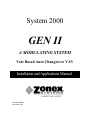
The GEN II is equipped with a Digital Display (O) on the GEN II controller that constantly
displays Leaving Air Temperature from the unit. At startup, this display also reports the number
of thermostats communicating with the GEN II controller. The display and 3 buttons (N) beneath the
display provide the installing contractor the ability to tailor the system to your specific application.
The GEN II controller is shipped from the factory configured for basic Gas/Electric operation.
However, the following should be checked as part of the initial installation setup procedures:
1. EH jumper (A) is installed by the factory on one pin for normal gas heat operation where the fan
is controlled by the HVAC system fan control. When a fan output is required from the GEN II
controller on a call for heat, place the EH jumper over both pins for several seconds and then
remove. Place the jumper tab on one pin.
2. O/B and HP jumpers (B&C) should both be on one pin or removed for GE operation.
3. PRIORITY jumper (D) should be on one pin.
Note: If the Priority opposing zone strategy is to be used, this jumper position will be changed
after the initial system start-up is completed.
See Advanced Feature Configuration.
4. Set the power switch (E) to ON.
5. Set the NIGHT DAY switch (L) to the DAY position.
6. Set the fan jumper (M) to AUTO for intermittent operation or ON for constant ON operation in
the Occupied mode.
7. Place the LOCK – UNLOCK switch (P) in the UNLOCK position.
8. Place the TIME/TEMP jumper (Q) on the middle and upper pins to control Y2 and W2 staging
on run time and supply air temperature.
Table of Contents
Page
System Overview ....................................................................................................................................1
System Overview Diagram ..................................................................................................................1
General Sequence of Operation ............................................................................................................2
Gas Electric Operation ...........................................................................................................................3
Controller ID Diagram ..........................................................................................................................3
Installation Controller ...........................................................................................................................3
GE Controller Configuration .................................................................................................................4
GE Advanced Configuration ................................................................................................................5
H&C Cut-out Temperature ...................................................................................................................5
Electric Heat Fan .................................................................................................................................5
nd
2 Stage cut in ....................................................................................................................................5
Heat Pump Operation .............................................................................................................................6
Controller ID Diagram ..........................................................................................................................6
Heat Pump Installation .........................................................................................................................7
Basic Configuration ..............................................................................................................................8
Heat Pump Advanced Configuration ...................................................................................................8
H&C Cut-out Temperature ...................................................................................................................8
nd
2 Stage Cut-in ...................................................................................................................................9
Zone Thermostat – ModStat
ModStat Installation ...........................................................................................................................10
Wiring Diagram ..................................................................................................................................10
ModStat Configuration ..................................................................................................................11-12
Supplemental Heat Applications ........................................................................................................13
Zone Thermostats – DIGICOM / DIGIHP
DIGICOM / DIGIHP Installation ....................................................................................................14-15
DIGICOM / DIGIHP Configuration ................................................................................................16-17
Voltage Polarity .................................................................................................................................17
System Start and Test .........................................................................................................................18
Troubleshooting ...................................................................................................................................18
Advanced Feature Configuration
Gas Electric and Heat Pump .............................................................................................................19
Occupied/Unoccupied Fan ................................................................................................................19
Opposing Call Changeover ...............................................................................................................19
Priority Demand ................................................................................................................................19
Thermostat Security – LOCK ............................................................................................................20
Air Balance ........................................................................................................................................20
Default Thermostat Set Points ..........................................................................................................21
Time Clock (GCLK) ...........................................................................................................................21
Zone Dampers
Round Dampers ................................................................................................................................22
Rectangular Dampers .......................................................................................................................23
D-Fuser .............................................................................................................................................24
Sizing ................................................................................................................................................25
Slaving Zone Dampers .....................................................................................................................25
Bypass Dampers – Electronic
Bypass Dampers ...............................................................................................................................26
Slaving Bypass Dampers ..................................................................................................................27
Bypass Damper with Integrated Pressure Control........................................................................28-29
SYSTEM OVERVIEW
The SYSTEM 2000 GEN II is a commercial modulating or 2-position zone control system controlling
2-17 independent zones per unit. The GEN II controller is designed for Auto Change- over, multistage Heat Pump (2C/3H) and Gas Electric (2C/2H) applications.
For modulating applications, the GEN II system uses the Zonex ModStat, which controls the “ST”
series, 3-wire, 24-volt, power open / power close round and rectangular dampers. For 2-position
damper applications, the GEN II system uses the Zonex MODS2 thermostat. The MODS2
thermostats control the TR round or TREC rectangular series, 2-wire, power close / spring open,
low pressure dampers. The TR / TREC series dampers are designed for systems 5 tons or less
(2000 CFM).
Sophisticated, integrated software allows for a wide range of system control and changeover
strategies, allowing the contractor to tailor the GEN II system to your specific application.
Additional features include LED status indication of all system functions, digital LAT display, fully
adjustable capacity control with on-board limit settings, and optional staging strategies. Night
setback operation is standard, with selectable 2-hour override at each stat, along with a unique
feature to remotely lock thermostats in the system.
The system provides the installing contractor with a simple startup diagnostic to minimize wiring
errors and speed installation.
GEN II is recognized as the Industry's easiest zone control system to install and wire. The GEN II
System operates over an unshielded two-wire data link, along with two 24 V power wires all daisy
chained from stat to stat with no home run wiring required. Three wires from the stat to actuator
control a modulating damper in each zone.
The GEN II system does not require a computer to set up or operate.
1
System 2000 GEN II offers the following additional control features:
1.
2.
3.
4.
5.
6.
Set Cooling and Heating capacity cut-out set points
nd
Adjustable timing to initiate 2 stage operation
Adjustable opposing call changeover timing
Priority demand votes on a stat-by-stat basis
Provide default occupied and unoccupied set points on every stat
Open all dampers for air balancing
System 2000 GEN II components:
• GEN II controller (includes integrated capacity control)
• Zone thermostats
• Power open / power close 24vac supply dampers
• Power open / power close 24vac bypass damper with static pressure control
• Communication cable (Belden 8740) twisted pair
• Time Clock (optional)
• 24vac 40va transformers: 1 to control system and dampers
1 for bypass damper and static pressure control
• Stand-alone thermostat – non-zoned system
GENERAL SEQUENCE OF OPERATION
When the GEN II controllers are powered up, the total number of addressed thermostats (ModStat,
MODS2, DIGICOM, DIGIHP) are determined and verified on the display. This confirms the
controller is communicating with all thermostats in the system. If there are no active heat or cool
calls detected, the supply dampers will modulate to 50% open (ModStat) or full open (MODS2) for
ventilation mode. Additional thermostats may be utilized to control stand-alone rooftop units with
DIGICOM / DIGIHP thermostats. The system blower operation can be configured for constant ON
or intermittent Auto. The controllers are shipped from the factory for Auto fan.
The System 2000 GEN II systems can be field configured for adjustable time based opposite call
changeover, vote based majority changeover, or priority vote changeover by thermostat
assignment. The GEN II controllers are shipped from the factory for 10-minute opposing call
changeover. The GEN II controllers “poll” the thermostats once per minute to determine the
thermostat demand status for heat and cool. The heat and cool changeover functions will operate
by the type of changeover selected on the controller. When the GEN II controllers change modes,
a 5-minute purge cycle is initiated before the changeover is completed.
On active heat or cool calls, the non-calling zones will modulate to the close position, or close 100%
depending on the thermostat being used. When the last calling zone is satisfied in either heat or
cool mode, the GEN II controllers will terminate the HVAC outputs after the next “poll”; and the
blower output will be de-energized (unless controller is configured for constant fan) for a 5-minute
purge cycle. During the purge cycle no heat or cool calls are recognized.
When the system is in the heating mode and calls for cooling are received, an opposing call timer
strategy operates. This timer is adjustable from 5–30 minutes. The factory default is 10 minutes.
At the end of the selected time period, if the opposing call is 3 degrees away from set point, heating
is turned off. After a 5-minute purge cycle, Cooling is turned on until the cool call is satisfied. If
necessary, GEN II will return to the heating mode. If all calls have been satisfied, dampers will
modulate to the 50% open position for ventilation. If the opposing zone strategy is not desired, this
feature may be disabled.
This mode may be enhanced by adding Priority votes to each thermostat in the system, thereby
weighting certain zones more than others. This Priority mode allows you to select 0, 1, or 2
additional votes for a thermostat that has unusual loads, like a conference room.
2
GAS ELECTRIC OPERATION
LEGEND
TERMINAL FUNCTIONS / CONNECTIONS
TX / RX – Data Transmit / Receive
A EH Jumper (Set Up Fan Operation for
Electric Heat)
B O/B Jumper (Heat Pump Only –
Reversing Valve Operation)
C H/P Jumper (Jump for Heat Pump
Operation)
D Priority Jumper (Allows for Priority Vote
Setup)
E On / Off Switch
F R C Power to ModStats (18 ga.
Thermostat wire)
G 24-Volt Transformer
H TC – TC Time Clock Terminals
I Unit Terminals
J S S Terminals – Leaving Air Sensor
(LAT)
K RX – TX Communications Wire
L Day / Night Switch
M Fan Jumper (Continuous or Auto)
N Up / Down / Set Buttons (High Limit,
Low Limit, Set)
O Digital Display (Leaving Air Temperature
and configuration)
P Lock / Unlock (Lock Thermostats)
Q Staging Strategy (Time / Temperature or
Time Only)
S S – Leaving / Supply Air Sensor Input
G – Fan Output
W2 – Auxiliary / Emergency Heat
O/B – Reversing Valve Output
Y2 – Stage 2 Cool Output
Y1 – Stage 1 Cool Output
R – 24vac from Unit Transformer
TC / TC – Time Clock Input for Occupied /
Unoccupied Operation
TR1 / TR2 – 24vac Power Input / Common
R / C – Stat Power Daisy Chain Stat to Stat
(18 ga. Thermostat wire)
General Installation Instructions
GEN II Controller
1.
Install the GEN II controller on an interior wall where the ambient temperature is between 32°120°F (0°- 48°C) non-condensing. This controller is to be installed in an accessible interior
area; not in attics or above ceilings.
2. The controller is to be powered by a dedicated 24vac 40va transformer.
The transformer secondary is wired to TR1 TR2 on the controller (G).
The secondary voltage to the controller must be 24 to 28vac.
3
3. Install the leaving air sensor (LAT) in the supply air, ahead of the bypass take-off. Sensor wires
are connected to the S S terminals on the controller (J). The LAT sensor leads may be
extended using standard 18/2 thermostat wire.
4. The leaving air sensor (LAT) is calibrated to the controller at the factory. However, the
calibration should be checked as part of the system setup procedures. If adjustments are
required, use the Blue potentiometer labeled R44 located in the upper left hand corner of the
GEN II controller. Screw the pot clockwise to lower the display temperature and counter clockwise to raise the temperature. NOTE: The display will update every 10 seconds.
5. Confirm you have connected the RX TX communication wires and R and C from the
thermostats to the controller (F&K), F = (R C), K = (TX RX). (Communication wire maximum is
4,000 ft. from the Command Center to the farthest ModStat, DIGICOM or DIGIHP.)
6. Connect the output wires from the controller to the HVAC system using standard 18 ga.
thermostat wire.
The LAT sensor leads may be extended using standard 18/2 thermostat wire.
Gas Electric - Basic GEN II Controller Configuration
The GEN II is equipped with a Digital Display (O) on the GEN II controller that constantly
displays Leaving Air Temperature from the unit. The display and 3 buttons beneath the display
provide the installing contractor the ability to tailor the system to your specific application.
The GEN II controller is shipped from the factory configured for basic Gas/Electric operation.
However, the following should be checked as part of the initial installation setup procedures:
1. EH jumper (A) is installed by the factory on one pin for normal gas heat operation where the fan
is controlled by the HVAC system fan control. When a fan output is required from the GEN II
controller on a call for heat, place the EH jumper over both pins for several seconds and then
remove. Place the jumper tab on one pin.
4
2. O/B and HP jumpers (B&C) should both be on one pin or removed, for GE operation.
3. PRIORITY jumper (D) should be on one pin.
Note: If the Priority opposing zone strategy is to be used, this jumper position will be changed
after the initial system start-up is completed.
See Advanced Feature Configuration.
4. Set the power switch (E) to ON.
5. Set the NIGHT DAY switch (L) to the DAY position.
6. Set the fan jumper (M) to AUTO for intermittent operation or ON for constant ON operation in
the Occupied mode.
7. Place the LOCK – UNLOCK switch (P) in the UNLOCK position.
8. Place the TIME/TEMP jumper (Q) on the middle and upper pins to control Y2 and W2 staging
on run time and supply air temperature.
GEN II Gas Electric Advanced Feature Configuration
Gas Electric Capacity Control - Cool and Heat cut-out temperature adjust
The factory setting for the Cool and Heat cut-out temperatures is 45°- 145°F (7°- 62°C). This can
be easily changed with the following procedure:
1. Cool cut-out temp – Press the DN button (N); “C” will be displayed and then the cut-out
temperature.
2. LOWER – Press the DN button; after the “C” is displayed, continue to hold the DN button until
the desired temperature is displayed; then release.
NOTE: The controller will not change the Cool cut-out lower than 40°F (4°C).
3. RAISE – Press the DN button; after “C” is displayed, immediately release the DN button and
press the UP button. Hold until the desired temperature reading is displayed, and release.
4. Press the DN button to verify the new cool cut-out temperature.
Heat cut-out temperature - Press and hold the UP button; after the “H” is displayed, use the same
procedure as above to raise or lower the displayed temperature.
Electric Heat - Fan Configuration
EH jumper (A) is installed by the factory on one pin for normal gas heat operation where the fan is
controlled by the HVAC system fan control. When a fan output is required from the GEN II
controller on a call for heat, place the EH jumper over both pins for several seconds and then
remove. Place the jumper tab on one pin.
2nd Stage Heat and Cool Cut-in Configuration
The GEN II controller is set up at the factory to stage Y2 and W2 cut-in operation based on a 3minute time delay and supply air temperature. This is done with a jumper which is placed on the
middle and upper pins on TIME/TEMP (Q), and the cut-in delay set at 03 (3 min) in the controller
program. The cut-in temperatures are fixed in the controller program at 57°F (13°C) and higher for
Y2 and 120°F (48°C) and lower for W2. The Y2 and W2 cut-in delay sequence can be field
adjusted (see below).
Adjust 2nd Stage Cut-in Time Delay
1. To increase the Y2 and W2 cut-in delay, press and hold the SET and DN buttons (N)
simultaneously. When 03 appears in the display, release the buttons and immediately press
the UP button and hold until the desired delay time is displayed, and release. The time delay
is fully adjustable from 3 - 20 minutes. To verify the change, press and hold the SET and DN
buttons simultaneously until the delay time is shown, and release.
5
2. To decrease the Y2 and W2 cut-in delay, press and hold the SET and DN buttons (N)
simultaneously. When delay time appears in the display, release the buttons and immediately
press the DN button and hold until the desired delay time is displayed, and release. To verify
the change, press and hold the SET and DN buttons until the delay time is shown, and release.
Configure 2nd Stage Cut-in For Time Delay and Thermostat Demand Only
nd
1. Place the 2 stage configuration jumper (Q) on the middle and lower pins - TIME.
2. If the cut-in time delay must be changed from the factory setting of 03 (3 min), follow the above
procedures to raise or lower the time delay value.
3. Verify time delay value by pressing the SET and DN buttons simultaneously.
HEAT PUMP OPERATION
LEGEND
TERMINAL FUNCTIONS / CONNECTIONS
TX / RX – Data Transmit / Receive
S S – Leaving / Supply Air Sensor Input
G – Fan Output
W2 – Auxiliary / Emergency Heat
O/B – Reversing Valve Output
Y2 – Stage 2 Cool Output
Y1 – Stage 1 Cool Output
R – 24vac from Unit Transformer
TC / TC – Time Clock Input for Occupied /
Unoccupied Operation
TR1 / TR2 – 24vac Power Input / Common
R / C – Stat Power Daisy Chain Stat to Stat
(18 ga. Thermostat wire)
6
A EH Jumper (Set Up Fan Operation for
Electric Heat)
B O/B Jumper (Heat Pump Only –
Reversing Valve Operation)
C H/P Jumper (Jump for Heat Pump
Operation)
D Priority Jumper (Allows for Priority Vote
Setup)
E On / Off Switch
F R C Power to ModStats (18 ga.
Thermostat wire)
G 24-Volt Transformer
H TC – TC Time Clock Terminals
I Unit Terminals
J S S Terminals – Leaving Air Sensor
(LAT)
K RX – TX Communications Wire
L Day / Night Switch
M Fan Jumper (Continuous or Auto)
N Up / Down / Set Buttons (High Limit,
Low Limit, Set)
O Digital Display (Leaving Air Temperature
and configuration)
P Lock / Unlock (Lock Thermostats)
Q Staging Strategy (Time / Temperature or
Time Only)
General Installation Instructions
GEN II Controller
1.
2.
3.
4.
5.
6.
Install the GEN II controller on an interior wall where the ambient temperature is between 32°120°F (0°- 48°C) non-condensing. This controller is to be installed in an accessible interior
area; not in attics or above ceilings.
The controller is to be powered by a dedicated 24vac 40va transformer.
The transformer secondary is wired to TR1 TR2 on the controller (G).
The secondary voltage to the controller must be 24 to 28vac.
Install the LAT air sensor in the supply air between the indoor coil and electric strip heat
elements.
The leaving air sensor (LAT) is calibrated to the controller at the factory. However, the
calibration should be checked as part of the system setup procedures. If adjustments are
required, use the Blue potentiometer labeled R44 located in the upper left hand corner of the
GEN II controller. Screw the pot clockwise to lower the display temperature and counter clockwise to raise the temperature. NOTE: The display will update every 10 seconds.
Confirm you have connected the RX TX communication wires and R and C from the
thermostats to the controller (F&K), F = (R C), K = (TX RX). (Communication wire maximum is
4,000 ft. from the Command Center to the farthest ModStat, DIGICOM or DIGIHP.)
Connect the output wires from the controller to the HVAC system using standard 18 ga.
thermostat wire.
The LAT sensor leads may be extended using standard 18/2 thermostat wire.
Heat Pump operation “O” reversing valve
Cool Call – When a majority active cool call is received by the GEN II controller, Y1, O/B and G
LEDs are illuminated; and the outputs are energized (within 1.5 to 3 minutes). After 3 minutes, if
the leaving air temperature is 58°F (14°C) or above, Y2 will energize for 2-stage systems. If the
supply air temperature drops one degree below the Cool cut-out temperature, Y1 and Y2 will deenergize for 4 minutes.
“B” reversing valve – Sequence of operation is the same: O/B is energized in the heat mode.
Heat Call - When a majority active heat call is received by the GEN II controller, Y1 and G LEDs are
illuminated; and the outputs are energized (within 1.5 to 3 minutes). If after 3 minutes the leaving
air temperature is 94°F (34°C) or less, Y2 will energize. If after 6 minutes of run time the leaving air
temperature is 91°F (32°C) or less, W2 will energize. If the supply air temperature exceeds 126°F
(52°C), Y1, Y2 and W2 (if energized) will drop out; and Y1 can then energize after a 4-minute time
delay. NOTE: If the system fan is configured for “AUTO” on the GEN II controller, the “G” output
will be de-energized in the temperature cut-out mode.
When the last active call satisfies, the GEN II controller goes into a 5-minute purge cycle with all
supply dampers closing; then all dampers modulate open for ventilation.
Emergency Heat - The GEN II emergency heat operation can be selected from any ModStat for
the entire control system. When the system operation mode is changed to Emergency Heat on a
given ModStat, the GEN II controller will recognize the mode change on the next system poll. The
thermostat which was used to select Emergency Heat does not have to make a heat call for the
GEN II controller to respond to the change. Once the GEN II controller changes the mode to
Emergency Heat, any ModStat in the system can make an emergency heat call. When the
controller receives a heat call in this mode, the compressor(s) are locked out and W2 is energized.
The GEN II controller will continue to make consecutive Emergency Heat calls until the ModStat(s)
have been changed back to the AUTO or HEAT mode.
7
To select Emergency Heat on any ModStat:
1. Press and hold the ModStat Menu button
2. When the mode display indicates Emg, release the Menu button; and immediately press and
hold the Select button to set the mode.
Heat Pump operation “B” reversing valve
By placing the O/B jumper (B) on both pins, the GEN II controller is configured for “B” reversing
valve operation. The operation and setup procedures are the same as with “O” mode reversing
valve, except the reversing valve will be energized for heat operation.
GEN II Heat Pump Basic Configuration
The GEN II controller is shipped from the factory
for Gas Electric operation.
The controller must be field configured for Heat
Pump operation.
Heat Pump configuration:
1. Switch controller to OFF (E).
2. Set the O/B jumper (B) on one pin for “O”
reversing valve (energizes for cool) or
set the O/B jumper (B) on both pins for “B”
reversing valve (energizes for heat).
3. Set the HP jumper (C) on both pins for Heat
Pump operation.
4. Set the Priority jumper (D) on one pin.
5. Set the TIME / TEMP jumper (Q) on the
middle and upper pins.
6. Set NIGHT / DAY switch (L) for DAY position.
7. Set LOCK / UNLOCK switch (P) to UNLOCK.
8. Switch the controller to ON (E).
9. Press the UP button (N), and verify the “H”
(cut-out) temperature reads 126°F (52°C) on the controller display (O).
NOTE: The heat cut-out temperature must not be changed from the factory setting.
GEN II Heat Pump Advanced Feature Configuration
Heat Pump Capacity Control - Cool and Heat cut-out temperature adjustment
When the GEN II controller is configured for Heat Pump (HP jumper (C) on both pins), the Cool and
Heat cut-out temperatures are 45°- 126°F (7°- 52°C). The cut-out temperatures can be changed
with the following procedure:
Heat cut-out temp – To eliminate the possibility of the Heat Pump tripping out on high head
pressure or short cycling in the heat mode, the heat cut-out temperature should never be changed
from the factory setting of 126°F (52°C).
1. Cool cut-out temp – Press the DN button (N); “C” will be displayed, then the cut-out
temperature.
2. LOWER – Press the DN button. After the “C” is displayed, continue to hold the DN button until
the desired temperature is displayed; then release.
NOTE: The controller will not change the Cool cut-out lower than 40°F (4°C).
8
3. RAISE – Press the DN button. After “C” is displayed, immediately release the DN button, and
press the UP button. Hold until the desired temperature reading is displayed; then release.
4. Press the DN button to verify the new cool cut-out temperature.
2nd Stage Heat and Cool Cut-in Configuration
The GEN II controller is set up at the factory to stage Y2 and W2 cut-in operation based on a 3minute time delay and supply air temperature. This is done with a jumper which is placed on the
middle and upper pins on TIME/TEMP (Q), and the cut-in delay set at 03 (3 min) in the controller
program. The cut-in temperatures are fixed in the controller program at 57°F (13°C) and higher for
Y2 and 120°F (48°C) and lower for W2. The Y2 and W2 cut-in delay sequence can be field
adjusted (see below).
Adjust 2nd Stage Cut-in Time Delay
1. To increase the Y2 and W2 cut-in delay, press and hold the SET and DN buttons (N)
simultaneously. When 03 appears in the display, release the buttons and immediately press
the UP button and hold until the desired delay time is displayed, and release. The time delay
is fully adjustable from 3 - 20 minutes. To verify the change, press and hold the SET and DN
buttons simultaneously until the delay time is shown, and release.
2. To decrease the Y2 and W2 cut-in delay, press and hold the SET and DN buttons (N)
simultaneously. When delay time appears in the display, release the buttons and immediately
press the DN button and hold until the desired delay time is displayed, and release. To verify
the change, press and hold the SET and DN buttons until the delay time is shown, and release.
Configure Y2 and W2 cut-in for time delay and thermostat demand only
nd
1. Place the 2 stage configuration jumper (Q) on the middle and lower pins - TIME.
2. If the Y2 cut-in time delay must be changed from the factory setting of 03 (3 min), follow the
above procedures to raise or lower the time delay value.
NOTE: The cut-in delay timing for W2 (Aux Heat) is set for approximately 3 minutes in the
control program and cannot be manually changed.
3. Verify time delay value by pressing the SET and DN buttons simultaneously.
9
Zone Thermostat - ModStat
Installation
Wiring
All 24-volt and communication wiring connections are made to terminal blocks on the thermostat
sub-base. The communication terminal block (RX TX/RX TX) is designed as a junction for two sets
of 22 ga. solid copper, twisted pair communications cable. The cable should be daisy chained from
thermostat to thermostat (use Belden 8740).
1. Install the thermostat sub-base on an interior wall away from direct sunlight, supply air currents,
or any heat generating source. Mounting screws and anchors are provided. The sub-base
may be installed on a vertical 2x4 electrical box.
2. Connect the control wires from the ModStat's R & C, to the GEN II controller (F). Verify R & C
polarity is the same on each thermostat (18 ga. Thermostat wire).
3. On the ModStat, connect the damper output wires from C-MC, RC and RO to the actuator
motor terminals. NOTE: For MODS2, terminal RO is not used.
4. Connect the RX TX communication wires on the right hand terminal block; there are 2 sets of
RX TX terminals to make the daisy chain wiring easier.
NOTE: The communication wire must be twisted pair Belden 8740, 8450 (shielded) or
82442 (plenum rated).
10
Configuration
Addressing
Each thermostat must have a unique address from 1-17.
1. Press and hold the Menu button until you see the system mode display on the lower right begin
to change modes; then press and hold the Heat/Cool button with the Menu button.
2. When the display shows “address,” release the Menu and Heat/Cool buttons, and press the UP
or DN button until the correct address is displayed in the upper right of the display.
3. After setting the address, the thermostat will automatically go back to normal operation; and the
set point temperature will replace the address number just programmed.
Display Temperature Calibration
Thermostats are calibrated at the factory and should require no further adjustment. However, the
display space temperature may be field calibrated by the following procedure:
1. Press and hold the Heat/Cool and Select buttons together; then press and release the UP
button to increase the display temperature by one degree.
2. To lower the temperature display, press the DN button once, after pressing the Heat/Cool and
Select buttons. This makes a 1-degree change.
Adjusting Set Points
The Heat or Cool set points can be displayed by pressing the Heat/Cool button; the set point will be
indicated on the upper right of the display.
The Heat and Cool set points can be individually set for the Occupied and Unoccupied modes.
Occupied Mode: H & C settings - Function switch (L) in the DAY position, or time clock in
Occupied.
Unoccupied Mode: H & C settings – Function switch (L) in the NIGHT position, or time clock
in Unoccupied.
11
Heat - If “Heat Setting” is displayed on the top right of the display, simply press the UP or DN button
to change the heat set point. If “Cool Setting” is displayed and you want to change the Heat set
point, press the Heat/Cool button twice to change from “Cool Setting” to “Heat Setting”. Then press
the UP or DN button to change the set point.
Cool - If “Cool Setting” is displayed on the top right of the display, simply press the UP or DN button
to change the cool set point. If “Heat Setting” is displayed and you want to change the Cool set
point, press the Heat/Cool button twice to change from “Heat Setting” to “Cool Setting”. Then press
the UP or DN button to change the set point.
Changing Mode
The thermostats are auto changeover, but specific modes may be selected. Auto mode is the
default.
Heat only – Press and hold the Menu button and note the mode display begin to change. Press
the Select button when Heat is displayed.
Emergency Heat - Press and hold the Menu button and note the mode display begin to change.
Press the Select button when Emg is displayed.
Cool only - Press and hold the Menu button and note the mode display begin to change. Press the
Select button when Cool is displayed.
System Off - Press and hold the Menu button and note the mode display begin to change. Press
the Select button when Off is displayed.
Auto mode – Press and release the Menu button.
Override
When the thermostat displays “Unoccupied” (top of display), a 2-hour temporary override may be
initiated by pressing the Override/Select button. When additional override time is required, press
the Override/Select button again.
Reheat
The ModStat can be field configured for reheat operation, including Fan Powered Boxes. To set
the ModStat for Reheat, press and hold the Heat/Cool and Select buttons together and then press
the Menu button; release all three buttons and the ° symbol will appear next to the heat and cool set
point temperature display.
NOTE: An air proving switch must be wired into the AUX output to protect the electric heating
devices.
Heat Call – The ModStat will send a signal for demand heating when the space temperature drops
1° below the heat set point temperature. If the temperature drops 2° below the heat set point
temperature, the AUX output will energize for auxiliary heat. The thermostat will end the active call
when the space temperature meets the heat set point.
When configured for Reheat, if the space temperature drops below the heat set point, the ModStat
will modulate the damper to 40% open. When the temperature drops one more degree, the AUX
terminal energizes the duct heat strip. The heat call will terminate when the space temperature
reaches the heat set point temperature. The “AUX” output will de-energize, and the damper will
modulate closed. If the system goes into the ventilation mode, the damper will then modulate open.
12
SUPPLEMENTAL HEAT APPLICATIONS
MODSTAT
SUBBASE
ModStat Terminal Designations
TX – Data transmit {twisted pair}
RX – Data receive
AUX – Reheat/AUX Heat Fan
RO – Run Open, damper
RC – Run Closed, damper {18 ga. stat wire}
R – 24vac power input
C-MC – 24vac power common
NOTE: A larger transformer may be needed to power fan relay and/or heat strip relay.
13
DIGICOM / DIGIHP THERMOSTATS
DESCRIPTION
The Zonex Systems DIGICOM (2H, 2C) and DIGIHP (3H, 2C) are
microprocessor based, auto changeover, stand-alone thermostats used to
control stand alone units with no dampers in the system. The DIGICOM is
the Gas Electric version and has two-stage heat / cool outputs with
selectable fan operation. The DIGIHP Heat Pump thermostats have twostage cool and three-stage heat outputs with selectable fan. The DIGICOM
and DIGIHP thermostats have a large, easy-to-read LCD display with a
distinctive grey backlight. The display backlight is continuously illuminated
in the Occupied mode and goes off in the Unoccupied mode.
The DIGICOM and DIGIHP are very easy to configure through the system program or to make
manual adjustments using the buttons located on the front cover.
These thermostats feature an onboard thermistor for precise temperature measurement. In the
event of power loss, the Heat and Cool set points are stored in a non-volatile memory, without the
need for battery backup.
The space ambient temperature is continually displayed with large, easy-to-read numbers. The
DIGICOM temperature display range is 45° - 95°F (7°- 35°C) and the DIGIHP temperature display
range is 55°- 95°F (12°- 35°C). Fan Mode, Heat or Cool set points and operation modes are all
indicated on the display.
Programmed set points can be manually adjusted at the thermostat or electronically locked through
the system program to provide limited manual set point adjustment. Two-hour override is provided
for after-hours temporary operation with a touch of a button.
INSTALLATION
Thermostat and terminal base
1. The thermostat is to be installed on the interior wall, away from drafts, supply air currents and
direct sunlight or any heat generating source.
2. To remove the thermostat cover, grasp the cover at the top and pull straight off; do not pivot the
cover from the base.
3. Install the thermostat terminal base to the wall using the provided anchors and screws. The
thermostat can also be mounted on a 2x4 electrical box using two #6-32” screws.
Wiring
The Zonex Systems DIGICOM and DIGIHP thermostats have been specifically designed to make
wall mounting and wire connections very easy. The thermostat terminal base has two separate
terminal blocks: the left side terminal block is for the 24vac control circuits, and the right side
terminal block is for the RX TX communication circuits. There are two sets of RX TX terminals on
the base to make daisy chain wiring from device to device straightforward and simple.
14
Wiring (Continued)
1. Use minimum 18-gauge AWG thermostat wire for the 24vac control circuits. The load on these
circuits must not exceed 1 amp. The voltage range on R and C must not exceed 28vac. Check
Polarity before applying the transformer wire to R and C. Refer to the Polarity Check diagram
on Page 17.
2. Connect the communication wires to the RX TX terminals. There are 2 sets of RX TX terminals
for “daisy chain” installation of this circuit. The communication wire specification is twisted pair
(Belden 8740) or shielded twisted pair wire (Belden 8450).
NOTE: When using shielded twisted pair wire (Belden 8450), just connect the shield conductors
together, as there is no electrical connection on the thermostat base terminals. The shield will be
landed on the GEN II controller on the G or TR2 terminal.
DIGICOM
Fig. 1
DIGIHP
Fig. 2
Blower Fan Relay
For electrical heat applications, which require a fan output on a call for heat, see Fig. 3.
Fig. 3
15
Configuration
1. Set the unique address for each thermostat from 01 to 20.
2. Press and hold the Menu button until you see the system mode display on the lower right begin
to scroll and change modes; then press and hold the Heat/Cool button with the Menu button.
3. When the display shows “address” and the set point temperature changes to the address
number, press the UP or DN button to raise or lower the number.
MANUAL ADJUSTMENTS
Heat and Cool Set point Display
Press the Heat/Cool button to display the Heat or Cool set point temperatures.
Temperature Set points
COOL Set point
1. Press the Heat/Cool button to display the Cool set point on the upper right.
2. Press the UP or DN buttons to change the Cool set point.
HEAT Set point
1. Press the Heat/Cool button to display the Heat set point on the upper right.
2. Press the UP or DN buttons to change the Heat set point temperature.
FAN Mode
To change the FAN operation to AUTO or On, press the UP and DN buttons together once to
toggle fan operation.
HVAC System Mode
To select Heat, Cool, Auto, Emergency Heat (HP only) or OFF, press and hold the Menu button;
and when the desired mode is displayed, press and hold the Select button; then release both to
confirm mode.
Override
When the system is in the Unoccupied mode, the thermostat provides a 2-hour override for afterhours system operation. To select the 2-hour override, press the Select button and note “Override”
indicated on the display, along with the backlight coming on. When additional override is required,
press the Select button again.
Calibration
When re-calibration is required, press and hold the Heat/Cool and Select buttons simultaneously
(the screen will flash). Then press the UP button once to increase temperature 1°, or press the DN
button once to decrease the temperature 1°. If additional calibration is required, repeat this step.
THERMOSTAT OPERATION
Display
The grey display backlight is constantly illuminated in the Occupied mode. The display backlight
goes off when in the Unoccupied mode. When in the Unoccupied mode, if any button is pressed,
the backlight will illuminate for 5 seconds. If the thermostat is placed in the override mode, the
backlight will illuminate until the 2 hours times out. To terminate override, press the Select button
again.
COOL – DIGICOM / DIGIHP: The thermostat will make a Y1 cool call when the space temperature
rises 1° above the cool set point. Y2 will energize when the space temperature rises 2° above the
cool set point. When the room temperature is less than 2° above the cool set point, Y2 deenergizes. Y1 de-energizes at set point. O or B is energized for the reversing valve circuit,
depending on configuration. The G circuit is energized for fan.
16
HEAT – DIGICOM: The thermostat will make a W1 heat call when the space temperature is 1
degree below the heat set point. W2 will energize when the space temperature is 2 degrees below
the heat set point. When the room temperature rises to within 2 degrees of the heat set point, W2
de-energizes. W1 de-energizes at set point.
NOTE: The “G” fan circuit on the DIGICOM thermostat is not energized in the Heat mode unless
the fan is set for ON operation.
HEAT − DIGIHP: The thermostat will make a Y1 heat call when the space temperature is 1 degree
below the heat set point. Y2 will energize when the space temperature is 2 degrees below the heat
set point. E (aux heat) will energize when the space temperature is 3 degrees below set point.
When the room temperature rises to within 2 degrees of the heat set point, E (aux heat) deenergizes. When the room temperature rises to within 1 degree , Y2 de-energizes. Y1 deenergizes at set point.
Emergency Heat – DIGIHP: When Emergency Heat is selected on the DIGIHP thermostat on a
call for heat, there is an output signal on “E” for backup heat and “G” for the fan. The compressor
circuits “Y1” and “Y2” are locked out during heat calls until Auto, Heat or Cool mode is selected.
The thermostat display will indicate when Emergency Heat has been selected.
DIGICOM – FAN operation for electric heat applications: A pilot relay may be required to energize
the fan for heat operation on electric heat applications. This relay is a 24vac coil – SPST and is
field supplied. The coil is energized from W1 and C from the DIGICOM thermostat terminal base.
VOLTAGE POLARITY CHECK ON DIGICOM / DIGIHP
System Start and Test
17
System Start and Test
1. Plug all thermostats into sub-bases. Turn GEN II power switch (E) to ON.
2. Choose any Thermostat and change its address from 25 to 1.
(See ModStat installation instructions – Configuration – Addressing).
3. Turn GEN II power switch OFF and then ON. The Display should flash 01 and then show the
leaving air temperature. This confirms your successful wiring and communication with that
thermostat.
4. If 01 is displayed, change the next thermostat’s address from 25 to 2. Turn the GEN II power
switch OFF and then ON. The display should flash 02 and then show the temperature. Readdress thermostats one at a time.
5. After each stat is re-addressed, turn the power switch off and then on. This will verify that the
re-addressed stat has been found by the GEN II Controller.
This procedure will simplify your installation and will confirm your wiring is correct and that the GEN
II controller can communicate over the 2-wire twisted pair data link with every thermostat in your
system.
Troubleshooting
When stat #1 is not found:
1. Check remaining stats to verify that all addresses are 25.
2. Check all R & C wiring for proper color-to-color connections. Even if the stats lighted, all R
wires at the thermostat must be connected to the GEN II R terminal. All C wires must be
connected to the GEN II C terminal. Confirm the daisy chain wiring is correct at this time.
3. Check RX & TX wires for proper color code and connections; polarity is imperative. All RX
connections must land on RX terminal on the following thermostat, and all TX connections must
connect to TX terminal on each thermostat.
4. Check R & C wires for opens or shorts.
Checking the Daisy Chain for opens or shorts:
Start from the GEN II board, and follow RX & TX wires to the first sub-base. Remove the RX & TX
wires going to the next sub-base in the link. Plug a stat into the first sub-base, and address it as #1.
Turn the GEN II power switch off, then on, to see if the display flashes.
1. If 01 is displayed, the first link of the daisy chain is OK. Reconnect the wires going to subbase.
2. Repeat these steps with a stat numbered 02. If the number 02 is displayed, then
Communication is confirmed.
When the correct number does not appear for a link, that link is either shorted or open. A link of the
daisy chain, which is open or shorted, must be repaired before the next thermostat is checked.
When the thermostats are correctly addressed, wired and linked, the total number of stats on your
job connected to the GEN II Control board will be displayed when the board is turned on.
After the correct number of connected thermostats is displayed, complete the wiring of AC unit or
heat pump connections; then make heat and cool calls to the GEN II Controller.
18
Advanced Feature Configuration - Gas Electric and Heat Pump
Occupied / Unoccupied fan operation
The factory setting for FAN operation is AUTO, with the FAN jumper (M) on the middle and lower
pins. In this setting, the fan circuit on “G” is only energized on an active cool call in Gas/Electric
mode or on an active heat call or cool call in Heat Pump mode. This applies to both Occupied and
Unoccupied modes. When the FAN jumper is in AUTO, there is no output on “G” with an active
heat call in Gas/Electric mode.
• Constant Fan in the Occupied (DAY) mode – Place the FAN jumper (M) on the center and
upper pins on ON. The fan output on “G” will be constant in the Occupied (DAY) mode and will
revert to auto in the Unoccupied (NIGHT) mode.
Opposing Call Changeover
The GEN II controllers are configured at the factory for Opposing Call Changeover with a time delay
setting of 10 minutes. With this configuration, any number of thermostats can make a like active
call (heat or cool). During this time, if a single thermostat makes an opposite call, a timer is started
at the next poll. This timer starts a time delay operation to allow the initial calling thermostats to
satisfy. If the initial active thermostats do not completely satisfy after 10 minutes, the dampers all
close and the controller drops out the HVAC outputs and goes into a 3-minute purge cycle. When
the purge cycle times out, the opposing thermostat call is initiated; and the appropriate HVAC
outputs are energized, and the supply damper opens. The thermostat with the opposing call must
now satisfy before the GEN II controller will recognize any of the initially calling thermostats.
The opposing call timer is factory adjusted for 10 minutes. However, the delay time can be field
adjusted from 5 to 30 minutes.
To increase the opposing call time delay:
1. Press the SET and UP buttons.
2. Release the SET button when the display changes, and continue to hold down the UP
button.
3. Release the UP button when the desired time is displayed.
To lower the time delay:
4. Press the SET and UP buttons.
5. Release the SET button, and immediately press and hold the DN (down) button until
the desired time is indicated; then release.
The Opposing Call feature can be disabled by performing steps 1 through 3 and then releasing the
UP button when the display indicates 32. With this feature disabled, the GEN II controllers will
operate changeover by majority vote from the zone thermostats.
Priority active Heat and Cool call operation
The GEN II controllers may be configured in the field for majority vote changeover but also assign
multiple votes for selected thermostats to enhance the changeover operation for special
requirements. Each thermostat represents one vote for heat or cool operation; a majority of active
calls will determine which mode the controller will operate in. With the Priority feature, any
thermostat may be assigned one or more additional votes to allow it to have priority to bring a mode
changeover more quickly. To keep proper overall temperature control, this priority vote change
should be limited to as few zones as possible.
Follow the procedure to implement Priority vote operation:
1. Determine which thermostat address is to have an additional one or two votes.
2. Place the PRIORITY jumper (D) on both pins.
19
3. Press and hold the SET and UP buttons (N), and the LED display will scroll through the number
of zones starting with 01.
4. When the display indicates the address (01 to 17) of the thermostat you want to add votes to,
release both buttons and press the DN button. The display will scroll through 00, 01, 02. To
add one additional vote, release the DN button when the display indicates 01 (this assigns a
total of 2 votes). To increase the votes by two, press the DN button and wait until the display
indicates 02 and then release the DN button (this assigns a total of 3 votes maximum).
5. To change the votes back to a single vote, press the DN button on the selected address and
release when the display indicates 00.
6. To review the vote status of all of the thermostats in the system, press the UP button; and the
display will first indicate the address number starting with 01and then the vote status for that
address. 00 = 1 vote 01 = 2 votes 02 = 3 votes. Upon review, if stat #1 has 2 votes, the
display will show Stat 01 followed by 02 signifying the number of Priority votes assigned to
Stat 1. Stat 02 will appear followed by a blank display, indicating only 1 vote; and Stat 03 will
appear followed by a blank screen, indicating no priority votes have been added to Stats 02 or
03.
7. Be certain to Place the PRIORITY jumper on one pin to put the controller back into normal
operation with the changes that were made.
Thermostat security - Set Point LOCK
The GEN II system provides the ability to electronically lock all of the zone thermostats (global).
When the thermostats are in the LOCK mode, there will be a padlock icon on each thermostat
display. The LOCK mode limits the manual changing of the heat and cool set points to a maximum
of 2° above or below the initial heat and cool set point temperatures.
To set the thermostats for the LOCK mode, simply change the switch position (P) from UNLOCK to
LOCK. All of the thermostats will change to LOCK on the next system poll. To unlock, set the
switch to the UNLOCK position; and the thermostats will drop the icon after the next system poll
and revert to normal operation.
Air Balance - Force Dampers Open
When performing an air balance on the supply air outlets, the GEN II controller provides a unique
feature to simplify this procedure. The GEN II controller will put all thermostats in a cool call which
will open the dampers 100% and bring on the system blower.
1. Place the EH jumper (A) over both pins
2. Press the SET and UP buttons (N) simultaneously – This puts a global cool set point of 58°F
(14°C) on all of the zone thermostats, and the controller energizes the “G” fan output only; Y1 is
not energized.
3. When the air balance procedure is completed, press the SET and DN buttons simultaneously,
which will assign 70°F (21°C) Heat and 75°F (23°C) Cool set points on all of the zone
thermostats.
4. Press and hold the SET and DN buttons; and while holding these buttons, remove the EH
jumper tab and place it on one pin. Release the SET and DN buttons. This procedure returns
the GEN II controller to normal operation. For Electric Heat fan configuration, see Page 5.
20
Default Thermostat Set Point Programming
Global default set points can be established from the GEN II controller.
The following procedure will provide a 75°F (23°C) Cool and 70°F (21°C) Heat occupied set point
along with Unoccupied 58°F (14°C) Heat and 85°F (29°C) Cool set point for every thermostat in the
system. This handy feature minimizes visits to the thermostats. To establish these default set
points:
1. EH jumper (A) - place the jumper over both pins.
2. Press the SET and DN button (N) simultaneously to engage default set points.
3. Remove the EH jumper, and place on one pin to put controller back into normal operation.
4. To view the unoccupied set points place the Night / Day switch (L) to the NIGHT position.
Following a poll, the thermostat backlights will turn off; and the unoccupied set points will be
displayed.
Time Clock
The GCLK is a 24vac 7-Day programmable time clock offered by Zonex Systems, exclusively for
the GEN II control system. This digital time clock will enable the control system to operate with
“Global” Occupied and Unoccupied schedules in a 7-day format. The GCLK is powered from the
GEN II controller power supply, and there is a backup battery to protect the time clock program for
up to 100 hours.
Installation
The GCLK must be installed on an interior wall next to the GEN II controller. Both the GEN II
controller and GCLK time clock must be easily accessible to monitor status and to make program
and function changes.
1. Remove the clear dust cover lens and loosen two screws on opposite corners of the clock
module.
2. Remove the housing that surrounds the time clock and the wire terminal cover.
3. Remove the clock module by pulling straight out from the base. Install the backing plate to the
wall with 3 screws (provided).
4. The GCLK is powered from TR1 and TR2 on the GEN II controller to terminals 1 and 2 on the
time clock terminal base.
5. The Normally Open switch contacts on the time clock 3 and 5 are wired to the TC terminals on
the GEN II controller.
6. Press the clock module back into place in the base, making certain that it is seated correctly.
7. Install the wire terminal cover and the clock housing with the 2 screws.
8. Install the clear dust cover lens in place.
Programming
See Programming and Configuration included with the GCLK.
21
ZONE DAMPERS
Zonex Systems zone dampers are
used in cooling/heating systems to
provide room by room zone
control. The damper is provided
with a factory mounted actuator.
Each zone damper is controlled
by a zone thermostat. More than
one damper can be controlled by
one zone thermostat. Use this
table to determine which zone
dampers to use.
DAMPER MODEL
STMPD Round Med. Pressure
STMRTD Rect. Med. Pressure
STCD Rect. Heavy Duty
D-FUSER
MAXIMUM
DIFFERENTIAL
PRESSURE
1.75”
1”
1.75”
0.1”
MAXIMUM
SYSTEM SIZE
Any Size
7.5 Tons
Any Size
Any Size
MAXIMUM
DUCT SIZE
18”
24”W x 20”H
48”W x 48”H
10”
Maximum Differential Pressure refers to the maximum static pressure drop in inches
of water column between the input (upstream) of the zone damper and the output
(downstream) when the damper is closed.
ROUND MEDIUM PRESSURE ZONE DAMPERS
Zonex Systems round medium pressure zone dampers are
recommended for systems with a maximum differential static
pressure up to 1.75”. This modulating power open/power close
damper is manufactured from 20-22 gauge galvanized steel with
rolled-in stiffening beads for superior rigidity. Mechanical minimum
and maximum set stops are provided and are easily adjustable. The
damper is elliptical, which allows the airflow to be tracked linearly.
The damper pipe is furnished with one crimped end and one straight
end for easy installation. Do not install damper in an inverted
position. A hat section supports a reversing 24vac, 60Hz, 2 VA
motor. A magnetic clutch allows for continuous power to the motor
and longer motor life. Motor drive time from full open to full close is
90 seconds.
MEDIUM PRESSURE (STMPD)
MODSTAT
ROUND MEDIUM PRESSURE DAMPER
PART NUMBERS AND SIZES
RO UND DIM ENSI O N AL D AT A
L
D
W
PART #
SIZE
D
L
W
STMPD06
STMPD08
STMPD10
STMPD12
STMPD14
STMPD16
STMPD18
6
8
10
12
14
16
18
6”
8”
10”
12”
14”
16”
18”
10”
10”
12”
14”
16”
18”
20”
9”
11”
13”
15”
17”
19”
21”
DAMPER TO
MODSTAT
WIRING
TYPICAL ROUND CAPACITIES
These air quantities were derived from a duct sizing
chart 0.1” friction loss per 100’ of duct. All CFMs
listed are approximate. For accurate selection, use
duct sizing table or device.
22
DUCT
DIAMETER
6”
8”
10”
12”
14”
16”
18”
NOMINAL
CFM
110
250
410
660
1000
1450
2000
DUCT VELOCITY
FPM
540
700
750
850
925
1070
1100
DAMPER
∆P “ WC
.014
.015
.015
.022
.035
.036
.036
RECTANGULAR ZONE DAMPERS
The rectangular zone dampers are available in either medium pressure or heavy duty. For systems under 7.5
tons, use medium pressure dampers. For systems 7.5 tons or over, use heavy duty dampers. Motor drive
time open and close is 90 seconds.
RECTANGULAR MEDIUM PRESSURE ZONE DAMPERS (STMRTD)
Zonex Systems rectangular medium pressure dampers are recommended for
systems under 7.5 tons with a maximum differential static pressure of 1”. These
are fully modulating, power open, power close dampers. They are constructed
from heavy duty aluminum and stainless steel. The damper is an opposed blade
type that slips into a 3¼-inch wide cutout in the existing duct and attaches with
screws via a duct mounting plate. The duct mounting plate is 5 inches wide. A
hat section supports a reversing 24vac, 60Hz, 2 VA motor. A magnetic clutch
allows for continuous power to the motor and longer motor life. Two set screws
connect the motor to the damper shaft, allowing quick motor replacement if
necessary. Motor drive time from full open to full close is 90 seconds.
MEDIUM PRESSURE RECTANGULAR DIMENSIONAL DATA
2¼”
Part Number STMRTD W x H
Sizes available from 8” x 6” up to 24” x 20”
W
5”
2½”
H
HEAVY DUTY RECTANGULAR DIMENSIONAL DATA
Part Number STCD W x H
Sizes available from 8” x 8” up to 48” x 48”
48” MAXIMUM WIDTH
2 ½”
D
MOTOR
H
D
RECTANGULAR HEAVY DUTY ZONE DAMPERS (STCD)
Zonex Systems rectangular heavy duty dampers are recommended for systems 7.5
tons or larger with a maximum differential static pressure of 1.75”. These are fully
modulating, power open / power close dampers made of 20 gauge “snaplock” steel
frame with S & Drive duct connections. Allow a 16” gap in the duct for the damper.
Formed steel blade stops incorporate a gasket for quiet operation and improved
structural rigidity. Rectangular dampers under 10” in height incorporate a single
blade design. Dampers 10” or over use opposed blade design. A full stall
motor, drawing 2 VA, drives the motor from full open to full close in 90 seconds.
23
RECTANGULAR DAMPER SELECTION
Rectangular Damper Capacities*
WIDTH IN INCHES
HEIGHT IN INCHES
8
10
12
14
16
18
20
22
24
26
28
30
32
8
10
12
14
16
18
20
22
24
26
28
30
32
300
400
500
610
710
820
925
1050
1175
1250
1400
1500
1600
400
540
680
825
975
1125
1300
1400
1590
1750
1975
2100
2175
500
680
850
1000
1200
1400
1600
1850
2000
2300
2550
2700
2850
610
825
1000
1250
1500
1750
2000
2250
2500
2900
3150
3425
3625
710
975
1200
1500
1800
2100
2450
2700
3000
3600
3950
4200
4425
820
1125
1400
1750
2100
2500
2850
3080
3600
4400
4600
4950
5100
925
1300
1600
2000
2450
2850
3400
3775
4000
4800
5500
5700
6000
1050
1400
1850
2250
2700
3080
3775
4300
4800
5100
6000
6350
6800
1175
1590
2000
2500
3000
3600
4000
4800
5400
6100
7000
7150
7600
1250
1750
2300
2900
3600
4400
4800
5100
6100
6700
7800
8400
8900
1400
1975
2550
3150
3950
4600
5500
6000
7000
7800
8400
9150
10000
1500
2100
2700
3425
4200
4950
5700
6350
7150
8400
9150
10000
11000
1600
2175
2850
3625
4425
5100
6000
6800
7600
8900
10000
11000
11250
* These air quantities were derived from duct sizing chart .1" friction loss per 100' of duct.
All CFMs listed are approximate.
For accurate selection use duct sizing table or device.
D-FUSER ZONE DAMPER
Zonex Systems D-Fuser is a combination zone damper and diffuser. It mounts in a standard 2’ x 2’ T-bar
ceiling opening, providing for simple installation and easy maintenance access. The D-Fuser is a cone
shaped fluidic nozzle with a platen that modulates up and down to control air flow. As the platen moves up,
the air volume is reduced; but the air velocity and throw remain constant. This keeps the air hugging the
ceiling, which maximizes room air mixing and minimizes the “waterfall” effect. The D-Fuser is a fully
modulating power open / power close damper using a 24vac 60Hz 2 VA motor. Motor drive time from full
open to full close is 90 seconds. The D-Fuser connects to round duct either on the side or top. Collars are
available for 6”, 7”, 8”, 9” and 10” duct.
12”
COLLAR:
PLACE ON SIDE
PLACE ON TOP
12”
6”
8”
2”
24”
AT NECK VELOCITIES UP TO 700 FPM
NC LESS THAN 30
10”
Neck Vel
∆P
CFM
Throw 50 FPM
Neck Vel
∆P
CFM
Throw 50 PM
Neck Vel
∆P
CFM
Throw 50 FPM
24
400
0.011
80
4’
400
0.019
140
5’
400
0.029
218
6’
500
0.016
98
4’
500
0.03
170
6’
500
0.045
273
8’
600
0.023
120
5’
600
0.045
207
7’
600
0.066
330
9’
700
0.035
135
6’
700
0.056
247
8’
700
0.09
382
10’
800
0.04
157
6’
800
0.041
280
9’
800
0.12
438
11’
900
0.055
176
7’
900
0.093
315
10’
900
0.146
497
12’
SIZING ZONE DAMPERS
If the ductwork already exists, simply size the damper to fit the ductwork. For new systems or retrofit jobs:
A. Determine CFM from heat gain or loss calculations.
B. Select damper size using either the round capacities chart, the rectangular capacities chart or by
using a duct sizing table or calculator.
C. Select a Zonex Systems damper to fit the duct size selected for that zone.
Make sure your zone dampers match the type specified in the table showing Maximum Differential Pressure.
INSTALLATION NOTES
1. Do not exceed 700 FPM in a register/diffuser branch duct.
2. If a damper is installed within 3 feet of a register/diffuser, install sound attenuating flex duct between
damper and outlet.
3. Zone dampers should be preceded by 2’ − 4’ of straight pipe where possible.
4. In attic installations and high humidity areas, the Zonex Systems damper should be insulated along with
the ductwork. The hat section on the round damper is delivered with insulation between the hat section
and pipe. Therefore, insulation should be applied to the round pipe and be butted against the hat section
(do not insulate the motor). The motor generates enough heat so that no condensation will develop on it.
5. Remember to allow a 16” gap in the duct for heavy duty rectangular dampers.
6. Medium pressure rectangular dampers slide into a 3¼” wide cutout in the side of the preexisting
ductwork.
7. Minimum open and close positioning is field adjustable on the actuator. The damper is shipped from the
factory to close 100%.
NOTE: Dampers should not be installed with motor upside down in the 6:00 position.
SLAVING UP TO THREE ZONE DAMPERS
Up to three dampers can be directly controlled by one thermostat. To wire two to three zone dampers to one
thermostat, use the following diagram shown. Remember to size the damper power transformer for the total
number of zone dampers. Each actuator draws 2 VA.
ZONE DAMPER
Mc
Ro
Rc
ZONE DAMPER
Mc
Ro
Rc
ZONE DAMPER
Mc
Ro
Rc
Mc Ro
Rc
MODSTAT
SLAVING MORE THAN
THREE ZONE DAMPERS
Use the following diagram
when a thermostat will be
controlling more than three
zone dampers.
Use an
additional 24V transformer
sized at 2VA per damper to
power the slaved dampers.
25
BYPASS DAMPERS – ELECTRONIC
ELECTRONIC BYPASS DAMPERS
Bypass dampers are used to provide constant air delivery through the air handling unit. This is done by
bypassing excess air from the supply duct back to the return duct. As a zone is satisfied, its zone damper
closes. When this happens, the bypass damper opens just enough to bypass the excess air. This will control
static pressure and noise at the diffusers.
The Electronic Bypass Damper is used on any size system over 5 tons. The damper can be round (STBP) or
rectangular (STCDBP) with integrated static pressure control; and multiple dampers can be slaved together.
SIZING ELECTRONIC BYPASS DAMPERS
The bypass damper is to be sized for the total
system CFM @ 1500 FPM. System CFM should
be calculated at 400 CFM per ton.
Example: A 5-ton system is rated at 2000 CFM
(5x400 = 2000). When calculated at 1500 FPM,
the bypass damper should be 16”.
Never
undersize the bypass damper.
ROUND BYPASS SELECTION TABLE
Diameter
CFM
PART #
SIZE
D
L
W
8”
10”
12”
14”
16”
18”
560
900
1250
1700
2200
2600
STBP08
STBP10
STBP12
STBP14
STBP16
STBP18
8
10
12
14
16
18
8”
10”
12”
14”
16”
18”
10”
12”
14”
16”
18”
20”
11”
13”
15”
17”
19”
21”
ROUND BYPASS DAMPER SELECTION
The Zonex Systems STBP damper is used for
round bypass applications. When you know the
bypass CFM requirements, use the ROUND
BYPASS SELECTION TABLE to confirm the
round damper size.
NOTE: Multiple round dampers can be slaved
from one static pressure control to provide the
correct capacity. One large rectangular bypass
damper may be used instead of multiple round
dampers. See below.
L
D
W
48” MAXIMUM WIDTH
RECTANGULAR BYPASS DAMPER
SELECTION
The Zonex Systems STCDBP WxH damper is
used for rectangular bypass applications. These
dampers are also sized for the total system CFM
rated at 1500 FPM. Multiple dampers can be
slaved from a single static pressure control.
W
H
D
RECTANGULAR BYPASS DAMPERS
SELECT FROM 8 x 8 thru 48 x 48
26
4”
HEIGHT IN INCHES
RECTANGULAR BYPASS SELECTION TABLE
8
10
12
14
16
18
20
22
24
28
32
36
40
44
48
8
667
833
1000
1167
1333
1500
1667
1833
2000
2333
2667
3000
3333
3667
4000
10
833
1042
1250
1458
1667
1875
2083
2292
2500
2917
3333
3750
4167
4583
5000
12
1000
1250
1500
1750
2000
2250
2500
2750
3000
3500
4000
4500
5000
5500
6000
14
1167
1458
1750
2042
2333
2625
2917
3208
3500
4083
4667
5250
5833
6417
7000
16
1333
1667
2000
2333
2667
3000
3333
3667
4000
4667
5333
6000
6667
7333
8000
18
1500
1875
2250
2625
3000
3375
3750
4125
4500
5250
6000
6750
7500
8250
9000
WIDTH IN INCHES
20
22
24
1667
1833
2000
2083
2292
2500
2500
2750
3000
2917
3208
3500
3333
3667
4000
3750
4125
4500
4167
4583
5000
4583
5042
5500
5000
5500
6000
5833
6417
7000
6667
7333
8000
7500
8250
9000
8333
9167 10000
9167 10083 11000
10000 11000 12000
28
2333
2917
3500
4083
4667
5250
5833
6417
7000
8167
9333
10500
11667
12833
14000
32
2667
3333
4000
4667
5333
6000
6667
7333
8000
9333
10667
12000
13333
14667
16000
36
3000
3750
4500
5250
6000
6750
7500
8250
9000
10500
12000
13500
15000
16500
18000
40
3333
4167
5000
5833
6667
7500
8333
9167
10000
11667
13333
15000
16667
18333
20000
44
3667
4583
5500
6417
7333
8250
9167
10083
11000
12833
14667
16500
18333
20167
22000
48
4000
5000
6000
7000
8000
9000
10000
11000
12000
14000
16000
18000
20000
22000
24000
Bypass air in CFM. Calculated at 1500 FPM.
Formula used: B = W x H / 144 x 1500, where B = Bypass air in CFM, W = damper width in inches, H = damper heightin inches,
144 = 144 sq. inches per sq. ft., 1500 = 1500 FPM.
ROUND AND RECTANGULAR
BYPASS DAMPER MOTORS
SLAVING BYPASS DAMPERS
Use only one Pressure Sensor when slaving two or more
Bypass Dampers together. Connect the Pressure Sensor
to one damper as described above. Connect the slave
dampers in parallel as shown. Up to 4 dampers can be
slaved to one Sensor. The slaved dampers will self synchronize each time the dampers reach full open or full
close.
DAMPER
ACTUATOR
*
*
*
RC RO MC
SLAVE
DAMPER
ACTUATOR
*
*
*
RC RO MC
TO NEXT SLAVE
BYPASS DAMPER
IF APPLICABLE
RC
RO
MC
To Static Press ure Control, as shown on the Bypass
Wiring Diagram on the next page.
27
BYPASS DAMPER with INTEGRATED PRESSURE CONTROL
(Part # STBP or STCDBP)
Bypass Damper with Integrated Pressure Control is used to control bypass operations. The bypass damper
modulates to maintain static pressure as zone dampers open and close. The bypass system reduces air noise
from the supply registers caused by excessive air velocity. If the system is configured for intermittent fan mode and
the system satisfies, there will be a 3-minute delay to allow for system purge, after which the bypass damper will
open to 25%, preventing noisy rush of air through supply registers when fan starts up on a call for heat or cool. If
the system is configured for fan continuous operation, the STBP (Round) or STCDBP (Rectangular) Electronic
Bypass will monitor static pressure continuously, providing constant control of system static.
INTEGRATED PRESSURE CONTROL
DESCRIPTION
A.
B.
C.
D.
E.
F.
5.
Supply air tube
24vac R and C
Damper Terminal RO, RC, MC
LED lights
Adjustable Potentiometer
TP1 Test Point
6.
7.
Drill ¼” hole into the side of the supply duct 2’
after the bypass and before the 1st supply takeoff. Mount pressure supporting block over ¼”
hole, align hole in block with hole in duct. Use
provided sheet metal screws.
Install air tube into supply air duct by slipping
supplied plastic tubing into holes in support block
and duct. Slip tube 3” into the duct. Pickup
tubing fits snugly into provided hole.
Connect pressure tube from static air pickup to
Integrated Pressure Control.
Fig. 2
Fig. 1
BYPASS DAMPER WITH INTEGRATED BYPASS
CONTROL SETUP
BYPASS DAMPER INSTALLATION
1.
2.
3.
1.
2.
3.
4.
Verify the bypass damper is sized properly to the
system and not undersized. (Bypass damper
sizing is recommended for 100% of system CFM.)
Bypass damper and controller are powered by a
dedicated 24vac 40VA transformer.
Do not install the bypass damper outside.
Locate the Integrated Pressure Control (IPC) and
air tube on the bypass damper.
28
Run all supply dampers to the full open position
and have blower motor running at 100% fan
speed. (See Note #1)
Manually close the bypass damper by pressing
in the release lever on the motor side of the
actuator. With the release lever pressed, rotate
the damper actuator collar to close the damper
and release the lever to lock the damper closed.
Quick Set Option: Turn the potentiometer on
the damper control board to the full left position
and slowly rotate RIGHT, until the “RC” RED
LED turns on. Now rotate LEFT just slightly, until
RC LED turns off.
The IPC is ready for
operation.
“RC” RED LED means damper closing.
“RO” GREEN LED means damper opening.
4.
Static Pressure Option: The Integrated Pressure
Control Board can be field configured for specified
static pressure using a multi meter and the static
pressure – voltage chart. (Exhibit A). This chart
shows voltage (DC) to inches of W.C. (static
pressure) relationship. Use a multi meter set on
VDC and place the leads on the “C” terminal and
“TP1” (test point one) next to the potentiometer.
The Voltage reading translates to inches of W.C.
BYPASS CHECKOUT FOR STATIC PRESSURE
CONTROLLER
1.
2.
3.
Make cool call at the zone thermostat of the
smallest zone.
Verify all zone dampers are closed except for
calling zone.
Verify noise at zone registers is not excessive.
Adjust the Integrated Pressure Control LEFT to
lower noise (airflow) or RIGHT to increase airflow
until too noisy.
BYPASS DAMPER WIRING DIAGRAM
WITH INTEGRATED BYPASS CONTROL
Note # 1: To open all dampers, it may be necessary
to remove Y outputs to unit on the zone control board
and to make full cool calls on all thermostats. This will
modulate dampers fully open and lock out compressor.
On Zonex Systems GEN II and ModCom II, use air
balance modes for simplified bypass setup.
29
ONLINE Step-by-Step Installation Instructions and Commissioning
www.zonexcontrols.com/gen.html
System 2000
GEN II
Hot Line: (800) 228-2966
5622 Engineer Drive
Huntington Beach, CA 92649
Factory: (714) 898-9963
Fax: (714) 898-6802
Visit our Web Site http://www.zonexsystems.com
Quick Quote Web Site:
www.zonexproducts.com
The easy way to Get Quotes Fast
PATENTED PRODUCT
Zonex Systems reserves the right to discontinue,
or change at any time, specifications or designs
without notice and without incurring obligations.
Copyright 2013 by Zonex Systems
Part #GENIIMAN
November 2013


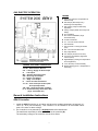
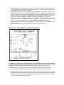
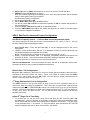

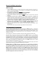
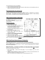
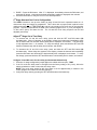

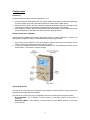


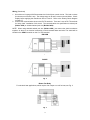
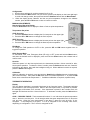
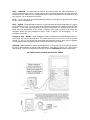

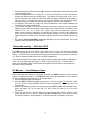

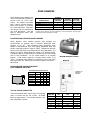

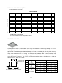
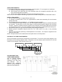

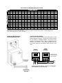
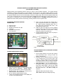


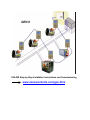


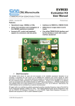
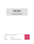
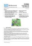

![[U4.84.01] Opérateur COMB_SISM_MODAL](http://vs1.manualzilla.com/store/data/006353312_1-84c0f0aa2b85e6ab7465faa950d278b0-150x150.png)
![[U4.84.01] Opérateur COMB_SISM_MODAL](http://vs1.manualzilla.com/store/data/006354551_1-0a996585a4efb054f257f659270030c7-150x150.png)
![[U4.84.01] Opérateur COMB_SISM_MODAL](http://vs1.manualzilla.com/store/data/006369926_1-bf5f185851d150b3bc2e73af807f0eaf-150x150.png)