1
Programming Guide
This guide describes how to use the Agilent 53150A, 53151A, and 53152A
Microwave Frequency Counters. The information in this guide applies to
instruments having the number prefix listed below, unless accompanied
by a “Manual Updating Changes” package indicating otherwise.
SERIAL PREFIX NUMBER:
3735A, US3925, and US4050 (53150A)
3736A, US3926, and US4051 (53151A)
3737A, US3927, and US4052 (53152A)
Agilent 53150A/151A/152A
Microwave Frequency Counter
Copyright Agilent
Technologies, Inc. 1999, 2002
Certification and Warranty
Before Cleaning
Certification
All Rights Reserved.
Reproduction, adaptation, or
translations without prior
written permission is
prohibited, except as allowed
under the copyright laws.
Agilent Technologies, Inc.
certifies that this product met
its published specification at the
time of shipment from the
factory. Agilent further certifies
that its calibration
measurements are traceable to
the United States National
Institute of Standards and
Technology (formerly National
Bureau of Standards), to the
extent allowed by the Institute’s
calibration facility, and to the
calibration facilities of other
International Standards
Organization members.
Disconnect the product from
operating power before
cleaning.
Printed: August 2002
Printed in U.S.A.
Manual part number
53150-90014
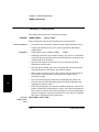
Warning Symbols That May
Be Used In This Book
Instruction manual symbol; the
product will be marked with
this symbol when it is necessary
for the user to refer to the
instruction manual.
Warranty
Agilent warrants
Agilent hardware, accessories
and supplies against defects in
materials and workmanship for
a period of one year from date of
shipment. If Agilent receives
notice of such defects during the
warranty period, Agilent will, at
its option, either repair or
replace products which prove to
be defective. Replacement
products may be either new or
like-new.
Agilent warrants that
Agilent software will not fail to
execute its programming
instructions, for the period
specified above, due to defects in
material and workmanship
when properly installed and
used. If Agilent receives notice
of such defects during the
warranty period, Agilent will
replace software media which
does not execute its
programming instructions due
to such defects.
For detailed warranty
information, see back matter.
WARNING
BODILY INJURY OR DEATH
MAY RESULT FROM
FAILURE TO HEED A
WARNING. DO NOT
PROCEED BEYOND A
WARNING UNTIL THE
INDICATED CONDITIONS
ARE FULLY UNDERSTOOD
AND MET.
CAUTION
Damage to equipment, or
incorrect measurement data,
may result from failure to
heed a caution. Do not
proceed beyond a CAUTION
until the indicated conditions
are fully understood and met.
Safety Earth Ground
Indicates hazardous voltages.
Indicates earth (ground)
terminal.
or
Indicates terminal is connected
to chassis when such connection
is not apparent.
An uninterruptible safety earth
ground must be maintained
from the mains power source to
the product’s ground circuitry.
WARNING
WHEN MEASURING POWER
LINE SIGNALS, BE
EXTREMELY CAREFUL AND
ALWAYS USE A
STEP-DOWN ISOLATION
TRANSFORMER WHICH
OUTPUT IS COMPATIBLE
WITH THE INPUT
MEASUREMENT
CAPABILITIES OF THIS
PRODUCT. THIS PRODUCT’S
FRONT AND REAR PANELS
ARE TYPCIALLY AT EARTH
GROUND. THUS, NEVER TRY
TO MEASURE AC POWER
LINE SIGNALS WITHOUT AN
ISOLATION TRANSFORMER.
Indicates Alternating current.
For additional safety and
acoustic noise information, see
back matter.
Safety Considerations
General
Safety Considerations
(cont’d)
Indicates Direct current.
This product and related
documentation must be
reviewed for familiarization
with this safety markings and
instructions before operation.
Agilent Technologies, Inc.
5301 Stevens Creek Boulevard
Santa Clara, California 95052-8059
7.C.NL.06.15.01.R1.M.CW6FC
Contents
1
Before You Start...
Introduction 1-2
Getting Started 1-3
How to Use This Guide 1-3
New Users 1-4
Experienced Programmers
Applications 1-5
Programming Guide Contents
Assumptions 1-7
Related Documentation 1-8
2
1-5
1-6
Command Summary
Introduction 2-2
Chapter Summary 2-2
Front Panel to SCPI Command Map 2-3
Agilent 53150A/151A/152A Command Summary 2-8
SCPI Conformance Information 2-8
IEEE 488.2 Common Commands 2-9
Agilent 53150A/151A/152A SCPI Subsystem Commands
Std/New Column 2-12
Parameter Form Column 2-12
*RST Response 2-19
3
2-12
Programming Your Counter
for Remote Operation
Introduction 3-2
Chapter Summary 3-3
Where to Find Some Specific Information 3-4
Programming Examples 3-4
Connecting the Counter to a Computer 3-5
To Connect With the GPIB 3-5
IEEE 488.1 Interface Capabilities 3-6
To Connect With the RS-232 Serial Interface 3-7
Remote/Local Operation 3-11
Programming Guide
iii
Contents
Overview of Command Types and Formats 3-12
Common Command Format 3-12
SCPI Command and Query Format 3-12
Elements of SCPI Commands 3-13
Subsystem Command Syntax 3-13
Common Command Syntax 3-13
Abbreviated Commands 3-14
Keyword Separator 3-14
Optional Keyword 3-14
Parameter Types 3-16
Parameter Separator 3-17
Query Parameters 3-17
Suffixes 3-17
Command Terminator 3-18
Using Multiple Commands 3-19
Program Messages 3-19
Program Message Syntax 3-19
Overview of Response Message Formats 3-21
Response Messages 3-21
Response Message Syntax 3-21
Response Message Data Types 3-23
Status Reporting 3-25
Status Byte Register and
Service Request Enable Register 3-27
Standard Event Status Register Group 3-30
The Operation and Questionable Data Status Register Groups 3-33
Programming the Counter for Status Reporting 3-41
Determining the Condition of the Counter 3-41
Resetting the Counter and Clearing
the Remote Interface—Example 1 3-42
Using the Standard Event Status Register to
Trap an Incorrect Command—Example 2 3-42
Using the Operation Status Register to Alert the Computer When
Measuring has Completed—Example 3 3-43
Programming the Counter to Display Results 3-46
Configuring the Counter's Display 3-46
iv
Programming Guide
Contents
Commands for Displaying Results 3-47
Command for Displaying Raw Results 3-47
Commands for Displaying Relative Results 3-47
Commands for Enabling and Disabling the Display 3-47
Programming the Counter to Synchronize Measurements 3-48
Synchronizing Measurement Completion 3-48
Resetting the Counter and Clearing the Interface 3-48
Using the *WAI Command 3-49
Using the *OPC? Command 3-49
Using the *OPC Command to Assert SRQ 3-50
Writing SCPI Programs 3-52
Programming Examples 3-54
Using BASIC 3-54
Using C 3-55
List of the Programming Examples 3-55
Making a Frequency Measurement (BASIC) 3-56
Making a Frequency Measurement (QuickBASIC) 3-57
Making a Frequency Measurement (C) 3-58
4
Command Reference
Introduction 4-2
:ABORt Command 4-4
:DISPlay Subsystem 4-5
Group Execute Trigger (GET) 4-7
:INITiate Subsystem 4-8
:INPut Subsystem 4-9
:MEASure Subsystem 4-10
Measurement Instructions
(:CONFigure, :FETCh, :MEASure, :READ) 4-10
Descriptions of the Measurement Functions 4-16
How to Use the Measurement Instruction Commands
:MEMory Subsystem 4-20
[:SENSe] Subsystem 4-22
[:SENSe]:FUNCtion Subtree 4-27
[:SENSe]:POWer Subtree 4-29
[:SENSe]:ROSCillator Subtree 4-30
Programming Guide
4-17
v
Contents
:STATus Subsystem 4-31
:STATus:OPERation Subtree 4-31
:STATus:QUEStionable Subtree 4-36
:SYSTem Subsystem 4-39
:SYSTem:COMMunicate Subtree 4-39
:TRIGger Subsystem 4-42
Common Commands 4-43
*CLS (Clear Status Command) 4-43
*DDT <arbitrary block> (Define Device Trigger Command)
*DDT? (Define Device Trigger Query) 4-44
*ESE (Standard Event Status Enable Command)
*ESE? (Standard Event Status Enable Query) 4-45
*ESR? (Event Status Register Query) 4-47
*IDN? (Identification Query) 4-48
*IST? (Instrument Status) 4-48
*OPC (Operation Complete Command) 4-49
*OPC? (Operation Complete Query) 4-49
*PRE (Parallel Poll Enable Register)
*PRE? (Parallel Poll Enable Register Query) 4-50
*RCL (Recall Command) 4-50
*RST (Reset Command) 4-51
*SAV (Save Command) 4-52
*SRE (Service Request Enable Command)
*SRE? (Service Request Enable Query) 4-53
*TRG (Trigger Command) 4-56
*TST? (Self-Test Query) 4-57
*WAI (Wait-to-Continue Command) 4-58
5
4-44
Errors
Introduction 5-2
Reading an Error 5-2
Error Queue 5-3
Error Types 5-4
No Error 5-4
Command Error 5-5
Execution Error 5-5
Device- or Counter-Specific Error
Query Error 5-6
Error List 5-6
vi
5-6
Programming Guide
1
Before You Start...
Chapter 1 Before You Start...
Introduction
1
Introduction
This programming guide contains programming information for the
Agilent Technologies 53150A, 53151A, and 53152A Microwave Frequency
Counters.
This guide assumes you are familiar with the front-panel operation of the
Counter. See the Agilent 53150A/151A/152A Operating Guide for
detailed information about front-panel operation. You should use this
programming guide together with the operating guide. Knowing how to
control the Counter from the front panel and understanding the
measurements you want to perform makes the programming task much
easier. The operating guide provides explanations and procedures for all
of the Counter’s measurement functions and contains the specifications
for the Counter.
By sending Standard Commands for Programmable Instruments (SCPI)
commands, you can remotely operate many of the Counter’s front-panel
functions via the General Purpose Interface Bus (GPIB) or the RS-232
serial interface. These programming commands conform to the Standard
Commands for Programmable Instruments (SCPI) Standard Version
1992.0. The SCPI standard does not completely redefine how to program
instruments over the GPIB or the RS-232 serial interface. However, it
does standardize the structure and content of an instrument’s command
set to reflect the best programming practices developed by people using
GPIB. It also establishes standard command mnemonics for similar
functions in all of the instruments that conform to the SCPI standard.
If you have programmed any Agilent instruments that have been released
over the last few years, you have probably seen a general trend toward the
techniques specified in the SCPI standard. For example, several
instruments are already using a hierarchy of commands that is similar to
the command structure defined by the SCPI standard.
1-2
Programming Guide
Chapter 1 Before You Start...
Getting Started
Getting Started
•
An explanation of how you should use the programming guide based on
your experience programming instruments and your testing requirements.
•
A description of the guide contents.
•
A statement of assumptions that are made in the guide.
•
A list of related documentation.
How to Use This Guide
How you use this guide depends upon how much you already know about
programming instruments and how complex your measurement
requirements are. Let’s start by establishing your programming background
and then discuss the type of measurements you want to perform.
NOTE
With two minor exceptions, the only difference between programming
the Counter using the GPIB interface and the RS-232 serial interface
is the manner in which you connect the Counter to the computer.
These exceptions are:
1. The Counter sends a command prompt over the RS-232 interface
(but not the GPIB) after receiving and executing each command.
2. When an error is detected (during the Self-Test or during operation),
the Counter automatically sends an error message (or messages) over
the RS-232 interface (error messages must be requested over the
GPIB). For additional information on error messages, see Appendix B
of the Agilent 3150A/151A/152A Operating Guide.
Programming Guide
1-3
1
Before attempting to program the Counter, take some time to familiarize
yourself with the content of this guide. The remainder of this chapter
contains the following information:
Chapter 1 Before You Start...
How to Use This Guide
New Users
1
What You Should Understand
As a new user, you must have some understanding of a high-level
language, such as BASIC or C, before you can use the command set
defined in this guide to control the Counter. (In Chapter 3, “Programming
Your Counter for Remote Operation,” there are programming examples
provided in BASIC, Microsoft® QuickBASIC, and Borland® Turbo C.)
However, whatever language you use, the command strings that control
the Counter remain the same.
Learning to Program the Counter
To learn how to program the Counter, perform the following:
1-4
•
Scan the summary tables in Chapter 2, “Command Summary,”
to get a feeling for the number and structure of commands
available to you.
•
Read and study map drawings in the section titled “Front Panel to
SCPI Command Map” in Chapter 2.
•
Read Chapter 3, “Programming Your Counter for Remote
Operation,” for an overview of SCPI concepts as they relate to the
Agilent 53150A, 53151A, and 53152A Frequency Counters. Look
at the flowcharts, which illustrate some of the decisions you must
make when programming the Counter.
•
Read the section at the end of Chapter 3 titled “Programming
Examples.”
•
Modify some of the programming examples to select specific
measurement functions. If the programs work, consider yourself
an experienced programmer and use Chapter 4, “Command
Reference,” as a reference for detailed information of all the
Counter's SCPI commands.
Programming Guide
Chapter 1 Before You Start...
How to Use This Guide
Experienced Programmers
Because the SCPI command set and some of the status reporting
techniques are new, we advise you to use the following sequence to learn
the Counter programming requirements:
•
Look over the steps for a new user, and perform any that you
think are applicable to your current level of knowledge. In
particular, look at the measurement techniques and examples
provided in Chapter 3, “Programming Your Counter for Remote
Operation.”
•
Review the summary tables in Chapter 2, “Command Summary.”
If this chapter contains sufficient information to get you started,
write some test programs to explore the Counter's capabilities.
If you need additional information on any command, refer to the
applicable command description in Chapter 4, “Command Reference.”
•
Review the remaining information in this guide to determine what
is applicable to your programming requirements.
If you need more information than is contained in this guide, see the
section in this chapter titled “Related Documentation.”
Applications
After you have read the appropriate information and written some
measurement programs, you may want to expand the scope of your
applications. The following two techniques are explained in detail:
•
If you are going to write interrupt-driven programs (or if you just
want to determine the status of the Counter), read the section
titled “Status Reporting” in Chapter 3.
•
If you are going to write programs to transfer data between the
Counter and an external computer, read the section titled
“Overview of Response Message Formats” in Chapter 3.
Programming Guide
1-5
1
If you have programmed other GPIB instruments, you are probably
familiar with many of the concepts and techniques discussed in this guide.
Using the SCPI commands is also very similar to using the earlier GPIB
commands. The main difference between the two command sets is the
hierarchy of the subsystem commands. (However, this type of structure
has previously been used on other instruments.)
Chapter 1 Before You Start...
Programming Guide Contents
1
Programming Guide Contents
The following information is contained in this guide:
1-6
•
Chapter 1 (this chapter),“Before You Start...,” is a preface that
introduces you to the programming guide.
•
Chapter 2, “Command Summary,” is a quick reference that
summarizes the Counter's programming commands. It provides
you with front-panel to SCPI command maps, SCPI conformance
information, and command-summary tables.
•
Chapter 3, “Programming Your Counter for Remote Operation,”
describes how to connect and set up the Counter for remote
operation, briefly explains the SCPI elements and formats,
describes status reporting, describes how to write programs, and
provides programming examples for each of the main tasks that
you want the Counter to perform.
•
Chapter 4, “Command Reference,” is a command dictionary that
describes the SCPI subsystems and IEEE 488.2 Common commands.
•
Chapter 5, “Errors,” lists all of the error messages the Counter
generates and the cause(s) for each error.
Programming Guide
Chapter 1 Before You Start...
Assumptions
Assumptions
As previously mentioned, this guide also assumes you are familiar with
the front-panel operation of the Counter. See the Agilent 53150A/
151A/152A Operating Guide for detailed information about front-panel
operation. Knowing how to control the Counter from the front panel and
understanding the measurements you need to perform makes the
programming task much easier.
Programming Guide
1-7
1
This guide assumes the Counter is correctly installed and interfaced to an
external computer. If it is not, and you intend to use the GPIB, see the
IEEE GPIB Interconnection information in Hewlett-Packard Company,
Tutorial Description of the Hewlett-Packard Interface Bus, 1987. (See the
section in this chapter titled “Related Documentation” for ordering
information.) If you intend to use the RS-232 serial interface, see the
section in Chapter 3 titled “To Connect With the RS-232 Serial Interface.”
Chapter 1 Before You Start...
Related Documentation
1
Related Documentation
This section contains a list of documentation that relates to the use of the
Counter. Additional information that may be useful is contained in the
following publications:
1. Agilent 53150A/151A/152A Operating Guide
(Agilent Part Number 53150-90013)
2. Beginner’s Guide to SCPI
(Agilent Part Number H2325-90002, July 1990 Edition).
3. Beginner’s Guide to SCPI, Barry Eppler (Hewlett-Packard Press,
Addison-Wesley Publishing Co. 1991).
4. Standard Commands for Programmable Instruments (SCPI),
(latest version).
This standard is a guide for the selection of messages to be included in
programmable instrumentation. It is primarily intended for instrument
firmware engineers. However, you may find it useful if you are
programming more than one instrument that claims conformance to
the SCPI standard. You can verify the use of standard SCPI commands
in different instruments.
To obtain a copy of this standard, contact:
SCPI Consortium
8380 Hercules, Suite P3
La Mesa, CA 91942
Phone: (619) 697-8790
FAX: (619) 697-5955
5. The International Institute of Electrical Engineers and Electronic
Engineers, IEEE Standard 488.1-1987, IEEE Standard Digital
Interface for Programmable Instrumentation.
This standard defines the technical details required to design and build
an GPIB (IEEE 488.1) interface. This standard contains electrical
specifications and information on protocol that is beyond the needs of
most programmers. However, it can be useful to clarify formal
definitions of certain terms used in related documents.
1-8
Programming Guide
Chapter 1 Before You Start...
Related Documentation
To obtain a copy of this standard, write to:
1
Institute of Electrical and Electronic Engineers Inc.
345 East 47th Street
New York, NY 10017 USA
6. The International Institute of Electrical Engineers and Electronic
Engineers, IEEE Standard 488.2-1987, IEEE Standard Codes,
Formats, Protocols, and Common Commands for Use with ANSI/IEEE
Std 488.1-1987 Programmable Instrumentation.
This standard defines the underlying message formats and data types
used in SCPI. It is intended more for firmware engineers than for
instrument users/programmers. However, it can be useful if you need
to know the precise definition of specific message formats, data types,
or common commands.
To obtain a copy of this standard, write to:
The Institute of Electrical and Electronic Engineers Inc.
345 East 47th Street
New York, NY 10017 USA
7. Hewlett-Packard Company, BASIC 5.0/5.1 Interfacing Techniques
Vol 2., Specific Interfaces, 1987.
This BASIC manual contains a good non-technical description of the
GPIB (IEEE 488.1) interface in Chapter 12, “The GPIB Interface.”
Subsequent revisions of BASIC may use a slightly different title for
this manual or chapter. This manual is the best reference on I/O for
BASIC programmers.
To obtain a copy of this manual, contact your nearest Agilent
Technologies Sales office.
8. Hewlett-Packard Company, Tutorial Description of the HewlettPackard Interface Bus, 1987.
To obtain a copy of this manual, contact your nearest Agilent
Technologies Sales office.
Programming Guide
1-9
Chapter 1 Before You Start...
1
Related Documentation
1-10
Programming Guide
2
Command Summary
Chapter 2 Command Summary
Introduction
Introduction
This chapter is a quick reference that summarizes the Counter’s
programming commands.
Chapter Summary
Front Panel to SCPI Command Map1
pg. 2-3
•
Agilent 53150A/151A/152A Command Summary2
pg. 2-8
2
•
•
•
SCPI Conformance Information
pg. 2-8
•
IEEE 488.2 Common Commands
pg. 2-9
•
Agilent 53150A/151A/152A SCPI Subsystem Commands pg. 2-12
*RST Response3
pg. 2-19
1 The section titled “Front Panel to SCPI Command Map” provides maps that show the front-panel keys and their
corresponding (or related) SCPI commands.
2 The section titled “Agilent 53150A/151A/152A Command Summary” lists the IEEE 488.2 Common Commands
and SCPI Subsystem commands in Table 2-1 and Table 2-2, respectively.
3 The section titled “*RST Response,” lists the states of all of the commands that are affected by the *RST
command in Table 2-3. This section also lists commands that are unaffected by *RST in Table 2-4.
2-2
Programming Guide
Chapter 2 Command Summary
Front Panel to SCPI Command Map
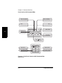
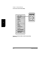
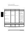
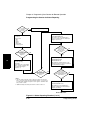
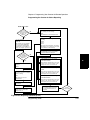
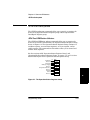
Front Panel to SCPI Command Map
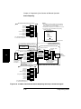
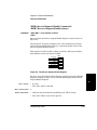
Figures 2-1 and 2-2 are command maps that shows the relationships between
the front-panel keys and the SCPI commands. This map should help you to
identify commands, if you are already familiar with the front panel.
Some SCPI Syntax Conventions:
An element inside brackets is optional. Note, the
brackets are not part of the command and should not
be sent to the Counter.
1|2
Means use either 1 or 2.
<numeric_value> Means enter a number.
SENSe
NOTE
Means you must use either all the upper case letters or
the entire word. The lower case letters are optional.
For example, SENS and SENSE are both valid.
However, SEN is not valid. (Note SENSe is used here
as an example, but this convention applies to all
SCPI commands.)
When you see quotation marks in a command’s parameter (shown in the
Parameter Form column in Table 2-2), you must send the quotation marks
with the command. Refer to the section titled “Using BASIC” on Page 3-54
of this guide for details on how to use double quotes or single quotes to
enclose the string parameter of a command.
Programming Guide
2-3
2
[ ]
Chapter 2 Command Summary
Front Panel to SCPI Command Map
3
2
Shift + Freq Offset
Shift + Pwr Offset
Rate
Avg
2
MODIFY
1
Reset/Local
Freq
Offset
Pwr
Offset
GPIB
Reset/
Local
Rate
Avg
Resol
Shift
Clear
+/-
Enter
Menu
Shift + GPIB
4
5
6
On/Off
Shift +
FREQ
Gate
12
11
Chan Select
Freq Offset On/Off
On/Off
Resolution
7
Display Power
9
8
POWER
Channel 2
dBm/ W
Chan
Select
Display
Power
Rel Freq
Rel Pwr
Offset
On/Off
Offset
On/Off
Power Offset On/Off
10
Figure 2-1. Front Panel Control to SCPI Command Map
(Part 1 of 2)
2-4
Programming Guide
Chapter 2 Command Summary
Front Panel to SCPI Command Map
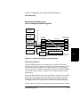
INITitiate[:IMMediate]
2
TRIGger[:SEQuence]:HOLDoff
3
[SENSe]:FREQuency:OFFSet
4
[SENSe]:POWer:AC:REFerence
5
[SENSe]:AVERage:COUNt
6
[SENSe]:AVERage:STATe
7
SYSTem:COMMunicate:GPIB:ADDRess
8
[SENSe]:FREQuency:RESolution
9
DISPlay:BACKground[:STATe]
2
1
10
[SENSe]:FUNCtion
11
[SENSe]:POWer:AC:REFerence:STATe
12
[SENSe]:FREQuency:OFFSet:STATe
13
[SENSe]:FUNCtion
Figure Front Panel Control to SCPI Command Map
(Part 2 of 2)
Programming Guide
2-5
Chapter 2 Command Summary
Front Panel to SCPI Command Map
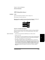
Shift + Menu
1
2
Menu
Reset/
Local
REF OSC
SAVE
Freq
Offset
Rate
On/Off
Shift
Clear
2
3 RECALL
4 CH1 LPF
5 FM
BAUD
6
PRESET
7
Instrument ID
8
OP HRS
9
BATT VOLTAGE
10
DO SELF TEST
11
PWR CORR
12
Figure 2-2. Front Panel Menu to SCPI Command Map
(Part 1 of 2)
2-6
Programming Guide
Chapter 2 Command Summary
Front Panel to SCPI Command Map
[:SENSe]:ROSCillator:SOURce
2
*SAV
3
*RCL
4
:INPut:FILTer[:LPASs][:STATe]
5
[:SENSe]:FILTer:FM:AUTO
6
:SYSTem:COMMunicate:SERial[:RECeive]:BAUD
7
*RST
8
*IDN?
9
See Service Guide
10
See Service Guide
11
*TST?
12
MEMory:CLEar[:NAME]
MEMory:DATA
[:SENSe]:CORRection:CSET:SELect
[:SENSe]:CORRection:CSET:STATe
2
1
Figure Front Panel Menu to SCPI Command Map
(Part 2 of 2)
Programming Guide
2-7
Chapter 2 Command Summary
Agilent 53150A/151A/152A Command Summary
Agilent 53150A/151A/152A Command
Summary
This section summarizes both the IEEE 488.2 Common and
Agilent 53150A/151A/152A Standard Commands for Programmable
Instruments (SCPI) commands in tabular format. IEEE 488.2 Common
Commands are listed first, followed by SCPI commands.
2
SCPI Conformance Information
The SCPI commands used in the Agilent 53150A/151A/152A Counters
are in conformance with the SCPI Standard Version 1995.0. The SCPI
command set consists of the following:
•
Common Commands as defined in IEEE 488.2-1987—listed and
summarized in Table 2-1.
•
SCPI Subsystem commands as confirmed (and listed) in the SCPI
Standard—the commands defined in Table 2-2 as “Std.”
•
SCPI Subsystem commands designed for the instrument in
conformance with SCPI standards but not yet listed in the SCPI
Standard—the commands defined in Table 2-2 as “New.”
•
Details of all Agilent 53150A/151A/152A commands can be found in
Chapter 4, “Command Reference.”
Information on the SCPI commands format, syntax, parameter, and
response types is provided in Chapter 3, “Programming Your Counter for
Remote Operation.”
2-8
Programming Guide
Chapter 2 Command Summary
Agilent 53150A/151A/152A Command Summary
IEEE 488.2 Common Commands
The Common Commands are general-purpose commands that are common
to all instruments (as defined in IEEE 488.2). Common Commands are
easy to recognize because they all begin with an “*” (for example, *RST,
*IDN?, *OPC). These commands are generally not related to
measurement configuration. They are used for functions like resetting
the instrument, identification, or synchronization.
Programming Guide
2-9
2
Table 2-1 lists the IEEE 488.2 Common Commands supported by the
Agilent 53150A/151A/152A in alphabetical order by mnemonic, name,
and function. More information concerning the operation of IEEE 488.2
status-reporting commands and structure can be found in the “Status
Reporting” section of Chapter 3. Standard explanations of the IEEE 488.2
Common Commands can be found in the ANSI/IEEE Std. 488.2-1987,
IEEE Standard Codes, Formats, Protocols, and Common Commands document.
Chapter 2 Command Summary
Agilent 53150A/151A/152A Command Summary
Table 2-1. IEEE 488.2 Common Commands
Command Name
Function
*CLS
Clear Status
Clears all event status registers summarized in the
status byte and empties the Error Queue.
*DDT <arbitrary block>
Define Device Trigger
Command
Defines which command is executed when the
Counter receives a GET or *TRG command.
*DDT?
Define Device Trigger
Query
Queries which command is executed when the
Counter receives a GET or *TRG command.
*ESE <NRf>
Standard Event
Status Enable
Sets the Standard Event Status Enable Register.
*ESE?
Standard Event
Status
Enable Query
Queries the Standard Event Status Enable Register.
*ESR?
Event Status Register
Query
Queries and then clears the Standard Event Status
Register.
*IDN?
Identification Query
Queries the Counter identification.
*IST?
Instrument Status
Query
Queries the current state of the parallel poll
response (Instrument Status).
*OPC
Operation Complete
Causes Counter to set the operation complete bit in
the Standard Event Status Register when all
pending operations (see Note at the end of table) are
finished.
*OPC?
Operation Complete
Query
Places an ASCII "1" in the Output Queue when all
pending operations (see Note at the end of table) are
completed.
*PRE <NRf>
Parallel Poll Enable
Register
Sets the value of the Parallel Poll Enable register.
*PRE?
Parallel Poll Enable
Register Query
Queries the value of the Parallel Poll Enable register.
*RCL <NRf>
Recall
Restores the state of the Counter’s user settings
from a copy stored in local non-volatile memory (0
through 9 are valid memory registers).
*RST
Reset
Resets the Counter to a known state, as defined in
this manual.
*SAV <NRf>
Save
Stores the current state of the Counter’s user
settings in local non-volatile memory (0 through 9
are valid memory registers).
*SRE <NRf>
Service Request
Enable
Sets the Service Request Enable register.
2
Mnemonic
2-10
Programming Guide
Chapter 2 Command Summary
Agilent 53150A/151A/152A Command Summary
Table 2-1. IEEE 488.2 Common Commands (Continued)
Command Name
Function
*SRE?
Service Request
Enable Query
Queries the Service Request Enable register.
*STB?
Status Byte Query
Queries the Status Byte and Master Summary
Status bit.
*TRG
Trigger
This trigger command is the device-specific analog
of the IEEE 488.1 defined GET. It initiates the
action specified by the *DDT command.
*TST?
Self-Test Query
Executes an internal self-test and reports the results.
*WAI
Wait-to-Continue
Makes the Counter wait until all pending operations
(see Note) are completed before executing
commands that follow the *WAI command.
Note: Pending operations include measurements in progress.
Programming Guide
2-11
2
Mnemonic
Chapter 2 Command Summary
Agilent 53150A/151A/152A Command Summary
Agilent 53150A/151A/152A SCPI Subsystem Commands
SCPI Subsystem commands include all measurement functions and some
general-purpose functions. SCPI Subsystem Commands use a hierarchy
relationship between keywords that is indicated by a colon (:). For example,
in the SYST:ERR? query, the “:” between SYST and ERR? indicates ERR?
is subordinate to SYST.
2
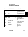
Table 2-2 lists the SCPI Subsystem Commands in alphabetical order by
the command keyword. The table shows the Subsystem commands
hierarchical relationship, related parameters (if any), and any associated
information and comments.
CAUTION
Not all commands have a query form. Unless otherwise stated in
Table 2-2, commands have both a command and a query form. Any
command in the table that is shown with a “?” at the end, is a “Query
Only” command.
Std/New Column
The Std/New column in Table 2-2 shows the status of the command with
respect to the SCPI standard. The “Std” commands operate as defined in
the SCPI standard and as defined in this guide.
The category of “New” consists of commands that could be:
•
SCPI approved but are not yet in the SCPI manual
•
Agilent approved and submitted for SCPI approval.
•
Not approved at all.
The “New” commands operate as defined in this guide.
Parameter Form Column
Refer to the section titled “Parameter Types” on Page 3-16, “Programming
Your Counter for Remote Operation,” for descriptions of the different
parameter types (such as <Boolean>, <NRf>, <arbitrary block>, etc.).
2-12
Programming Guide
Chapter 2 Command Summary
Agilent 53150A/151A/152A Command Summary
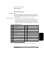
Table 2-2. Agilent 53150A/151A/152A SCPI Command Summary
Keyword/Syntax
Parameter Form
Std/New Comments
Std
Event; no query. Resets the trigger system
and aborts any measurement in progress.
Places the trigger system in the IDLE state.
:CONFigure
Std
See Measurement Instructions in this table.
:DISPlay
Std
Subsystem. Controls the selection and
presentation of textual information on the
display.
Controls whether or not the entire display is
visible.
:ENABle
[:WINDow]
:BACKground
[:STATe]
<Boolean>
Std
<Boolean>
New
Turns the LCD display backlight ON or
OFF.
:FETCh
Std
See Measurement Instructions in this table.
:INITiate
Std
Subsystem. Controls the initiation of
measurements.
Sets the instrument for continuously
initiated or user-initiated measurements.
Event; no query. Causes the instrument to
initiate and complete one full measurement
cycle.
:CONTinuous
<Boolean>
[:IMMediate]
Std
:INPut
Std
:FILTer
[:LPASs]
[:STATe]
Std
Std
<Boolean>
:MEASure
Std
Std
Std
Programming Guide
Subsystem. Controls the characteristics of
the instrument’s Channel 1 input port.
Subtree. Controls a filter that can be
inserted in the path of the measurement
signal.
Subtree. Selects the Low-PASs filter.
Enables or disables the Channel 1
low-pass filter (approx. 50 KHz).
See Measurement Instructions in this table.
2-13
2
:ABORt
Chapter 2 Command Summary
Agilent 53150A/151A/152A Command Summary
Table Agilent 53150A/151A/152A SCPI Command Summary (Continued)
Keyword/Syntax
Parameter Form
Measurement Instructions
:CONFigure[:SCALar]:<function>
Std/New
See <parameters> and
<source_list> below.
Std
Configures the instrument
to perform the specified
measurement.
Std
Returns the function
configured by the last
:CONFigure or :MEASure
command.
Std
Configures the instrument,
initiates measurement,
and queries for the result
(i.e., provides a complete
measurement sequence.
2
:CONFigure?
Comments
:MEASure:[:SCALar]:<function>?
See <parameters> and
<source_list> below.
:READ[:SCALar]:<function>?
Std
:FETCh[:SCALar]:<function>?
Std
Initiates measurement,
and queries for the result.
(Performs a :FETCh? on
“fresh” data.)
Queries the measurement
made by a previous
:MEASure, :READ, or
:INITiate command.
*The <function> and corresponding <parameters> and <source_list> are defined below:
<function>
<parameters>
[,<source_list>]*
[:VOLTage]:FREQuency
:POWer[:AC]
[<expected_value>[,<r
esolution>]]
[<expected_value>[,<r
esolution>]]
[,(@1) | (@2)]
[,(@2)]
Std/New
Std
Std
___________________________________
*<source_list> has the same syntax as SCPI <channel_list>. For example, a frequency
measurement on channel 2 uses (@2) to specify channel 2.
2-14
Programming Guide
Chapter 2 Command Summary
Agilent 53150A/151A/152A Command Summary
Table 2-2. Agilent 53150A/151A/152A SCPI Command Summary (Continued)
Keyword/Syntax
Parameter Form
:MEMory
:CLEAr[:NAME]
<name>
Std
Std
<name>, <data>
<name>
Std
Std
:DATA
:DATA?
Std
Subsystem. Manages instrument memory.
Event; no query. Restores the frequency
values in the named correction profile to the
default values and sets all loss values to
zero.
Stores data in the named correction profile.
Queries the data in the named correction
profile.
Query only. Returns the number of available
*SAV/*RCL states in the instrument.
:READ
Std
See Measurement Instructions in this table.
[:SENSe]
:AVERage
[:STATe]
:COUNt
Std
New
New
New
Subsystem setup commands.
Subtree. Configures the averaging function.
Turns averaging ON and OFF.
Specifies the number of measurements to
combine when AVERage:STATe is ON.
Subtree. Configures the power-correction
function.
Selects a power-correction profile.
:CORRection
:CSET
:SELect
:STATe
:DATA?
<Boolean>
<numeric_value>
Std
<character_data>
CORR1 | CORR2 . . . CORR9
<Boolean>
Std
<data_handle>
Std
"[XNONe]FREQuency [1 | 2]"
"[XNONe]POWer [2]"
:FILTer
:FM
:AUTO
<Boolean>
Programming Guide
Std
Std
Std
Std
New
When STATe is ON, power measurements
are modified according to the data in the
correction profile selected with :SELect.
Query only. Returns the current
measurement result data of the SENSe
subsystem.
Frequency on channel 1 or 2.
Power on channel 2.
Subtree. Controls the use of filtering
routines in the instrument.
Turns automatic FM compensation ON or
OFF.
2-15
2
:NSTates?
Std/New Comments
Chapter 2 Command Summary
Agilent 53150A/151A/152A Command Summary
Table 2-2. Agilent 53150A/151A/152A SCPI Command Summary (Continued)
Keyword/Syntax
Parameter Form
[:SENSe] (cont.)
:FREQuency
Std/New Comments
Std
<numeric_value>[frequency unit]
Std
<Boolean>
New
:RESolution
<numeric_value>[frequency unit]
Std
:TRACking
<character_data>
FAST | SLOW | OFF
New
:OFFSet
2
:STATe
:FUNCtion
[:OFF]
[:ON]
:STATe?
:POWer
:AC
:REFerence
:STATe
Std
<sensor_function>[,<sensor_function>]
"[XNONe]FREQuency [1 | 2]"
"[XNONe]POWer [2]"
<sensor_function>[,<sensor_function>]
"[XNONe]FREQuency [1 | 2]"
"[XNONe]POWer [2]"
<sensor_function>
Std
Query that returns a Boolean value which
indicates whether the specified
<sensor_function> is ON or OFF.
Subtree. Configures the instrument for
power measurement on channel 2.
Sets a reference amplitude (in dB) for
display of power measurements.
Determines whether amplitude is measured
in absolute or relative mode.
Subtree. Controls the reference oscillator.
Std
<Boolean>
Std
Std
2-16
Subtree. Selects the <sensor_function>(s)
to be sensed by the instrument.
Selects the <sensor_function>(s) to be
turned OFF.
Selects the <sensor_function> to be sensed
by the instrument.
<numeric_value>
<character_program_data>
INTernal | EXTernal
Sets the frequency-measurement
resolution.
Selects one of three signal-tracking modes.
Std
Std
:ROSCillator
:SOURce
New
Subtree. Controls the frequency-measuring
capabilities of the instrument.
Sets a reference frequency for all other
absolute frequency settings in the
instrument.
When STATe is ON, frequency
measurements are modified by the value of
FREQ:OFFset.
Std
Sets the selection of a reference timebase
(INTernal or EXTernal).
Programming Guide
Chapter 2 Command Summary
Agilent 53150A/151A/152A Command Summary
Table 2-2. Agilent 53150A/151A/152A SCPI Command Summary (Continued)
Keyword/Syntax
Parameter Form
:STATus
Std
:OPERation
:CONDition?
:ENABle
Std/New Comments
Std
Std
<non-decimal numeric> | <NRf>
Std
:NTRansition
<non-decimal numeric> | <NRf>
Std
:PTRansition
<non-decimal numeric> | <NRf>
Std
:PRESet
Std
:QUEStionable
[:EVENt]?
Std
Std
:CONDition?
<non-decimal numeric> | <NRf>
:ENABle
Std
Std
Programming Guide
Sets and queries the positive transition filter
for the Operation status reporting structure
Event; No query. Presets the enable
registers and transition filters associated
with the Operation and Questionable status
reporting structures.
Subtree.
Query only. Queries and then clears the
Questionable Data Event Status Register.
Query only. Queries the Questionable Data
Condition Status Register.
Sets the Questionable Data Event Status
Enable Register structures.
2-17
2
[:EVENt]?
Std
Subsystem. Controls the SCPI-defined
(Operation and Questionable)
status-reporting structures.
Subtree.
Query only. Queries the Operation
Condition Status Register.
Sets the Operation Event Status Enable
Register.
Query only. Queries and then clears the
Operation Event Status Register.
Sets and queries the negative transition
filter for the Operation status reporting
structure.
Chapter 2 Command Summary
Agilent 53150A/151A/152A Command Summary
Table 2-2. Agilent 53150A/151A/152A SCPI Command Summary (Continued)
Keyword/Syntax
Parameter Form
2
:SYSTem
Std/New Comments
Std
:COMMunicate
Std
:GPIB
[:SELF]
:ADDRess <numeric_value>
:SERial
[:RECeive]
<numeric_value>
:BAUD
:ERRor?
Std
Subsystem. Collects the functions that are
not related to instrument performance.
Subtree. Collects together configuration of
control/communication interfaces.
Subtree. Controls the GPIB.
Std
Std
Sets the GPIB address of the instrument.
Subtree.
Std
Std
:KEY
:CATalog?
Std
Std
:VERSion?
Std
Sets the baud rate.
Query only. Queries the oldest error in the
Error Queue and removes the error from the
queue (first in-first out). See Chapter 5 for
error definitions.
Simulates the pressing of a front-panel key.
Query only. Returns a list of defined key
codes.
Query only. Returns the SCPI version
number with which the Counter complies.
:TRIGger
[:SEQuence]
:HOLDoff
Std
Subsystem.
Std
When INIT:CONT ON, this command
specifies the length of the delay between
measurements.
<numeric_value>
2-18
Programming Guide
Chapter 2 Command Summary
*RST Response
*RST Response
The IEEE 488.2 *RST command returns the instrument to a specified
state optimized for remote operation. (Use *CLS to clear the status event
registers and the SCPI error queue.)
The states of command settings affected by the *RST command are
described in Table 2-3. Table 2-4 lists command settings that are
unaffected by *RST.
2
Table 2-3. Agilent 53150A/151A/152A *RST State
Command Header
Parameter
State
*DDT
<arbitrary block>
#14INIT
:DISPlay[:WINDow]:BACKground[:STATe]
:DISPlay:ENABle
<Boolean>
<Boolean>
ON
ON
:INITiate:CONTinuous
<Boolean>
OFF
:INPut:FILTer:[:LPASs][:STATe]
<Boolean>
OFF
[:SENSe]:AVERage:[STATe]
[:SENSe]:AVERage:[COUNt]
[:SENSe]:FILTer:FM:AUTO
<Boolean>
<numeric_value>
<Boolean>
OFF
1
ON
[:SENSe]:CORRection:CSET:SELect
[:SENSe]:CORRection:CSET:STATe
[:SENSe]:FREQuency:OFFset
[:SENSe]:FREQuency:OFFset:STATe
[:SENSe]:FREQuency:RESolution
[:SENSe]:FREQuency:TRACking
[:SENSe]:FUNCtion:OFF
<character_data>
<Boolean>
<numeric_value>[frequency unit>
<Boolean>
<numeric_value>[frequency unit>
<character_program_data>
<sensor_function>
[:SENSe]:FUNCtion[:ON]
[:SENSe]:POWer:AC:REFerence
[:SENSe]:POWer:AC:REFerence:STATe
[:SENSe]:ROSCillator:SOURce
<sensor_function>
<numeric_value>
<Boolean>
INTernal | EXTernal <Boolean>
CORR1
OFF
0
OFF
1 Hz
SLOW
“FREQuency 1”,
“POWer 2”
“FREQuency 2”
0
OFF
INTernal
:TRIGger[:SEQuence]:HOLDoff
<numeric_value>
0
Programming Guide
2-19
Chapter 2 Command Summary
*RST Response
Table 2-4. Unaffected by *RST
Item
*ESE
*PRE
*SRE
:MEMory:NSTates?
:STATus subsystem—all command settings
2
:SYSTem subsystem—all command settings
2-20
Programming Guide
3
Programming Your Counter
for Remote Operation
Chapter 3 Programming Your Counter for Remote Operation
Introduction
Introduction
This chapter provides remote-operation setup and programming
information. You can use this information to configure the Counter to
operate as a remote device.
NOTE
Most of this chapter deals with programming the Agilent 53150A/
151A/152A Counters using SCPI and IEEE 488.2 commands. With two
minor exceptions, the only difference between programming these
Counters using the GPIB interface and the RS-232 serial interface is
he manner in which you connect the Counter to the computer.
These exceptions are:
3
1. The Counter sends a command prompt over the RS-232 interface
(but not the GPIB) after receiving and executing each command.
2. When an error is detected (during the Self-Test or during operation),
the Counter automatically sends an error message (or messages) over
the RS-232 interface (error messages must be requested over the
GPIB). For additional information on error messages, see Appendix B
of the Agilent 53150A/151A/152A Operating Guide.
3-2
Programming Guide
Chapter 3 Programming Your Counter for Remote Operation
Introduction
Chapter Summary
•
Connecting the Counter to a Computer
pg. 3-5
•
Overview of Command Types and Formats
pg. 3-12
•
Elements of SCPI Commands
pg. 3-13
•
Using Multiple Commands
pg. 3-19
•
Overview of Response Message Formats
pg. 3-21
•
Status Reporting
pg. 3-25
•
Programming the Counter for Status Reporting
pg. 3-41
•
Programming the Counter to Display Results
pg. 3-46
•
Commands for Displaying Results
pg. 3-47
•
Programming the Counter to Synchronize Measurements
pg. 3-48
•
Writing SCPI Programs
pg. 3-52
•
Programming Examples
pg. 3-54
3
Programming Guide
3-3
Chapter 3 Programming Your Counter for Remote Operation
Introduction
3
Where to Find Some Specific Information
•
To Connect With the GPIB
pg. 3-5
•
Configuring the GPIB
pg. 3-5
•
IEEE 488.1 Interface Capabilities
pg. 3-6
•
To Connect With the RS-232 Serial Interface
pg. 3-7
•
Making an RS-232 Cable
pg. 3-7
•
Remote/Local Operation
pg. 3-11
•
Common Command Format
pg. 3-12
•
SCPI Command and Query Format
pg. 3-12
•
Abbreviated Commands
pg. 3-14
•
Optional Keyword
pg. 3-14
•
Parameter Types
pg. 3-16
•
Parameter Separator
pg. 3-17
•
Command Terminator
pg. 3-18
•
Program Messages
pg. 3-19
•
Response Messages
pg. 3-21
Programming Examples
•
Making a Frequency Measurement (BASIC)
pg. 3-56
•
Making a Frequency Measurement (QuickBASIC)
pg. 3-57
•
Making a Frequency Measurement (C)
pg. 3-58
3-4
Programming Guide
Chapter 3 Programming Your Counter for Remote Operation
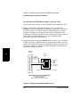
Connecting the Counter to a Computer
Connecting the Counter to a Computer
To program the Counter to operate remotely, you need to interface the
Counter with a computer. The Agilent 53150A, 53151A, and 53152A
provide two interfaces for remote, computer-controlled operation—
GPIB and RS-232. The following sections describe how to connect and
configure both interfaces for remote Counter operation.
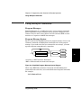
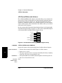
To Connect With the GPIB
To connect the Counter to a computer using the GPIB, install an GPIB
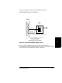
cable (such as the Agilent 10833A cable) between the two units, as shown
in Figure 3-1.
Computer (Rear Panel)
Agilent 10833A/B/C/D
GPIB Cable
3
Counter (Rear Panel)
Made in U.S.A.
with domestic and foreign content
OPTIONS
001 Oven Time Base
002 Battery
Main ~ Power
Reference 10 MHz
Auxillary
WARNING:
In
or
Out
To avold electric shock,
do not remove covers.
No user-serviceable parts inside.
Refer all servicing to qualified personnel.
This unit must be earth grounded.
11 TO 18 VDC
LINE VOLTAGE:
FUSE:
FUSE:
EXT DC
RS-232
90-260VAC
50/60 Hz
100-120VAC 0.5A, SB 250V
200-240V,
0.25A,SB 250V
GPIB
Figure 3-1. GPIB Interconnection
Configuring the GPIB
The Counter’s GPIB operates in Addressed (talk/listen) mode, which
provides bi-directional communication. The Counter can receive commands
and setups from a computer, and it can send data and measurement
results. There is one configurable setting related to GPIB communication—
the GPIB Address.
Programming Guide
3-5
Chapter 3 Programming Your Counter for Remote Operation
Connecting the Counter to a Computer
The following section, titled “Changing the GPIB Address,” provides
instructions for setting the GPIB address from the Counter’s front panel.
Once the Counter is in Remote mode, all front-panel keys except the
Reset/Local key are disabled. As long as local-lockout is off, pressing the
Reset/Local key returns the counter to Local mode.
NOTE
3
Changing the GPIB Address
NOTE
1
Press and release the Shift key, and then press GPIB (Resol). The GPIB
ADDR menu is displayed, the current GPIB address is shown to the right
of the blinking indicator (>), and the LED indicator between the arrow
keys flashes.
2
Press the right-arrow key. The blinking indicator changes direction
(from > to <), and the current GPIB address blinks.
3
Press (or press and hold) the up-arrow or down-arrow key to change the
GPIB address (the available addresses are 1 to 30).
4
When your desired address is displayed, press the Enter key. The address
you selected is assigned, and the display returns to its normal operating
mode. You must press the Enter key to complete the entry.
To configure the Counter so that the a specific GPIB address is
automatically assigned each time you turn the Counter on, select the
address, and then save your current settings in SAV 0. The settings in
SAV 0 are recalled each time the Counter is turned on.
IEEE 488.1 Interface Capabilities
The Agilent 53150A/151A/152A Counter has the following IEEE 488.1
Interface capabilities:
SH1
AH1
T6
L3
3-6
SR1
RL1
PP1
DC1
DT1
C0
E1
Programming Guide
Chapter 3 Programming Your Counter for Remote Operation
Connecting the Counter to a Computer
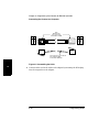
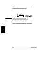
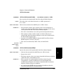
To Connect With the RS-232 Serial Interface
The Agilent 53150A, 53151A, and 53152A use an RJ12 modular connector
for the RS-232 interface. This connector is accessible through the back
panel of the counter, as shown in Figure 3-2.
Made in U.S.A.
with domestic and foreign content
ISM 1-A
OPTIONS
001 Oven Time Base
002 Battery
Main ~ Power
Reference 10 MHz
Auxillary
WARNING:
In
or
Out
To avold electric shock,
do not remove covers.
No user-serviceable parts inside.
Refer all servicing to qualified personnel.
This unit must be earth grounded.
11 TO 18 VDC
AC POWER
100 – 130 VAC, 50/60/400 Hz 75 VA
220 – 240 VAC, 50/60 Hz 75 VA
EXT DC
FUSE
1.0 A T
250 V
RS-232
GPIB
3
RS-232 (RJ12) Connector
Figure 3-2. Location of the RS-232 (RJ12) Connector
To connect the Counter to a computer using the RS-232 interface,
you need a serial cable that has an RJ12 modular connector at the
Counter end and a female DB25 connector at the computer end.
Making an RS-232 Cable
Most computers use male DB25 connectors for their serial ports.
Therefore, you must use either a cable with an RJ12 plug at the Counter
end and a female DB25 connector at the computer end or a double-ended
RJ12 cable and an RJ12-to-DB25F adapter to interface the Counter with a
computer. Since pre-manufactured RJ12/DB25 cables are rare, it is
probably most efficient to obtain the necessary parts, and assemble the
cable yourself.
Programming Guide
3-7
Chapter 3 Programming Your Counter for Remote Operation
Connecting the Counter to a Computer
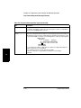
Assembling the DB-25/RJ12 Adapter and the Cable
Use the following procedure to wire the adapter and assemble the cable:
1
Obtain a male DB25 to female RJ12 adapter, such as the Voltrex
MAK206F (manufactured by SPC Technology) or equivalent, and either a
6-conductor male-to-male RJ12 cable of a suitable length or a similar
length of 6-conductor, flat telephone cable and two RJ12 plugs. RJ12
modular plugs (SPC part number TA30-6) and 6-conductor, flat telephone
cable (SPC part number TXW6151) are also available from SPC
Technology (and other manufacturers).
2
Adapter kits like the Voltrex MAK206F usually include a pre-wired RJ12
modular receptacle, a DB25F connector, and the adapter body, or wiring
shroud. Wire the RJ12 receptacle to the DB25F connector according to the
diagrams in Figure 3-3, and then assemble the adapter according to the
instructions included in the kit.
3
DB-25F
(Female)
14
15
16
17
18
19
20
21
22
23
24
25
1
2
3
RJ12
(Male)
RED (RXD)
BLK (TXD)
4
1
5
6
7
8
2
GRN (GND)
3
4
5
6
9
Pin 1:
Pin 2:
Pin 3:
Pin 4:
Pin 5:
Pin 6:
Not Used
TXD
RXD
GND
Not Used
Not Used
10
11
12
(Viewed from wire (back) side of the connectors)
13
SPC Technology Voltrex Brand
Part number MAK206 F
DB-25F (female) to RJ12 (male) Adapter
Figure 3-3. Wiring the RJ12/DB25 Adapter (1 of 2)
3-8
Programming Guide
Chapter 3 Programming Your Counter for Remote Operation
Connecting the Counter to a Computer
DB-25F
(Female)
25
24
23
22
21
20
19
18
17
16
15
14
RJ12
(Male)
13
12
11
10
9
8
7
GRN (GND)
6
5
4
3
2
1
6
5
4
3
2
1
Pin 4: GND
Pin 3: RXD
Pin 2: TXD
BLK (TXD)
RED (RXD)
(Viewed from front side of the connectors)
SPC Technology Voltrex Brand
Part number MAK206 F
DB-25F (female) to RJ12 (male) Adapter
3
Figure 3-3. Wiring the RJ12/DB25 Adapter (2 of 2)
3
Attach an RJ12 modular plug to each end of a suitable length of
6-conductor, flat telephone cable as shown in Figure 3-4. Be sure to attach
the connectors in the orientations shown in the figure.
Programming Guide
3-9
Chapter 3 Programming Your Counter for Remote Operation
Connecting the Counter to a Computer
Wire
No.
6
5
4
3
2
1
Color
Pin #
BLU
YEL
GRN
RED
BLK
WHT
6
5
4
3
2
1
RJ12
Modular Plug
SPC Technology
Part number TA 30-6
6
5
4
3
2
1
Pin #
6
5
4
3
2
1
1
2
3
4
5
6
Wire
No.
6
5
4
3
2
1
Color
BLU
YEL
GRN
RED
BLK
WHT
SPC Technology, 6−Conductor
Flat Telephone Wire
Part number TXW6151
3
Figure 3-4. Assembling the Cable
4
Connect either end of the cable to the adapter by inserting the RJ12 plug
into the receptacle on the adapter.
3-10
Programming Guide
Chapter 3 Programming Your Counter for Remote Operation
Connecting the Counter to a Computer
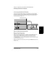
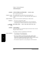
Connecting with the Serial Interface
Connect the female DB25 connector on the adapter to the male DB25
serial-port connector on the computer, and then insert the RJ12 plug at
the other end of the cable into the RJ12 receptacle on the back of the
counter as shown in Figure 3-5.
Computer (Rear Panel)
Serial Cable
Counter (Rear Panel)
Made in U.S.A.
with domestic and foreign content
OPTIONS
001 Oven Time Base
002 Battery
Main ~ Power
Reference 10 MHz
Auxillary
WARNING:
In
or
Out
To avold electric shock,
do not remove covers.
No user-serviceable parts inside.
Refer all servicing to qualified personnel.
This unit must be earth grounded.
11 TO 18 VDC
LINE VOLTAGE:
FUSE:
FUSE:
EXT DC
RS-232
90-260VAC
50/60 Hz
100-120VAC 0.5A, SB 250V
200-240V,
0.25A,SB 250V
GPIB
3
Figure 3-5. RS-232 Serial Interconnection
Remote/Local Operation
When the counter is connected to a computer via the GPIB, and it is in
Remote mode, the Rmt indicator is visible on the display, and the
Counter settings cannot be affected using the front-panel controls.
The Reset/Local key can be used to manually return the counter to local
control (if local-lockout is off).
When the Counter is in Local mode, the front-panel Rmt indicator in the
display is off.
Programming Guide
3-11
Chapter 3 Programming Your Counter for Remote Operation
Overview of Command Types and Formats
Overview of Command Types and Formats
There are two types of Agilent 53150A/151A/152A programming commands:
IEEE 488.2 Common Commands and Standard Commands for
Programmable Instruments (SCPI). The format of each type of command
is described in the following paragraphs. (Refer to Chapter 2, “Command
Summary,” for SCPI conformance information.)
Common Command Format
The IEEE 488.2 Standard defines Common Commands as commands that
perform functions like reset, self-test, status byte query, and
identification. Common Commands always begin with the asterisk (*)
character, and may include parameters. The command keyword is
separated from the first parameter by a space character. Some examples
of Common Commands are as follows:
3
*RST
*IDN?
*RCL 1
SCPI Command and Query Format
SCPI commands perform functions like instrument setup. A subsystem
command has a hierarchical structure that usually consists of a top level
(or root) keyword, one or more lower-level keywords, and parameters.
The following example shows a command and its associated query:
:DISPlay:ENABle:ON
:DISPlay:ENABle?
In this example, DISPlay is the root-level keyword, ENABle is the secondlevel keyword, and ON is the command parameter.
3-12
Programming Guide
Chapter 3 Programming Your Counter for Remote Operation
Elements of SCPI Commands
Elements of SCPI Commands
A program command or query is composed of functional elements that
include a header (or keywords with colon separators), program data, and
terminators. These elements are sent to the Counter over the GPIB or the
RS-232 interface as a sequence of ASCII data messages. Examples of a
typical Common Command and Subsystem Command are:
OUTPUT 712;"*CLS"
OUTPUT 712;":DISP:ENAB ON;:FREQ:RES 1KHz"
Subsystem Command Syntax
Figure 3-6 shows the simplified syntax of a Subsystem Command. You must
use a space (SP) between the last command mnemonic and the first
parameter in a Subsystem Command. Note that if you send more than one
parameter with a single command, you must separate adjacent
parameters with a comma.
:
3
,
:
sp
mnemonic
parameter
?
suffix
Note: sp = space. ASCII character decimal 32.
Figure 3-6. Simplified Program Command Syntax Diagram
Common Command Syntax
Figure 3-7 shows the simplified syntax of a Common Command. You must
use a space (SP) between the command mnemonic and the parameter in a
Common Command.
Programming Guide
3-13
Chapter 3 Programming Your Counter for Remote Operation
Elements of SCPI Commands
*
sp
mnemonic
parameter
?
Note: sp = space. ASCII character decimal 32.
Figure 3-7. Simplified Common Command Syntax Diagram
Abbreviated Commands
3
The command syntax shows most keywords as a mixture of upper- and
lowercase letters. Uppercase letters indicate the abbreviated spelling for
the command. For better program readability, you may send the entire
keyword. The Agilent 53150A/151A/152A accepts either command form
and is not case sensitive.
For example, if the command syntax shows DISPlay, then DISP and
DISPLAY are both acceptable forms. Other forms of DISPlay, such as
DISPL or DISPLA are illegal, and they generate errors. You may use
upper and/or lower case letters. Therefore, DISPLAY, display, and
DiSpLaY are all acceptable.
Keyword Separator
A colon (:) always separates one keyword from the next lower-level
keyword as shown below:
:DISPlay:ENABle?
Optional Keyword
Optional keywords are those which appear in square brackets ([ ]) in the
command syntax. (Note that the brackets are not part of the command
and are not sent to the Counter.)
Suppose you send a second level keyword without the preceding optional
keyword. In this case, the Counter assumes you intend to use the optional
keyword and responds as if you had sent it.
3-14
Programming Guide
Chapter 3 Programming Your Counter for Remote Operation
Elements of SCPI Commands
Examine the portion of the [:SENSe] subsystem shown below:
[:SENSe]
:FREQuency
:RESolution
The root-level keyword [:SENSe] is an optional keyword. To set the
Counter’s frequency resolution, you can use either of the following:
:SENS:FREQ:RES
or
:FREQ:RES
3
Programming Guide
3-15
Chapter 3 Programming Your Counter for Remote Operation
Elements of SCPI Commands
Parameter Types
Table 3-1 contains explanations and examples of parameter types.
Parameter types may be numeric value, Boolean, literal, NRf, string,
non-decimal numeric, or arbitrary block.
Table 3-1. Command and Query Parameter Types
TYPE
EXPLANATIONS AND EXAMPLES
<numeric
value>
Accepts all commonly used decimal representation of numbers including optional signs,
decimal points, and scientific notation:
123, 123e2, -123, −1.23e2, .123, 1.23e−2, 1.23000E−01.
Special cases include MINimum and MAXimum as follows: MINimum selects minimum value
available, and MAXimum selects maximum value available.
Queries using MINimum or MAXimum return the associated numeric value.
<Boolean>
Represents a single binary condition that is either true or false:
1 or ON, 0 or OFF (Query response returns only 1 or 0.)
3
An <NRf> is rounded to an integer. A non-zero value is interpreted as 1.
<literal>
Selects from a finite number of choices. These parameters use mnemonics to represent each
valid setting. An example is the INPut:COUPling AC | DC command parameters (AC | DC).
<NRf>
Flexible numeric representation.
<string>
A string parameter is delimited by either single quotes or double quotes. Within the quotes, any
characters in the ASCII 7-bit code may be specified.
The following BASIC statement sends a command containing a <string> parameter:
OUTPUT 703;"FUNC ‘FREQ’"
<non-decimal
numeric>
Format for specifying hexadecimal (#H1F), octal (#Q1077), and binary (#B10101011) numbers
using ASCII characters. May be used in :STATus subsystem commands.
<arbitrary
block>
The syntax is a pound sign (#) followed by a non-zero digit representing the number of digits in
the subsequent decimal integer. The decimal integer specifies the number of 8-bit data bytes
being sent. This is followed by the actual data. The terminator is a line feed asserted with EOI.
For example, for transmitting 8 bytes of data, the format could be:
Number of digits
that follow
Actual data
Terminator
# 2 08<8 bytes of data> <new line> ^EOI
Number of bytes
to be transmitted
The “2” indicates the number of digits that follow and the two digits “08” indicate the number of data
bytes to be transmitted; a zero-length block has the format: #0<new line>^EOI; <new line> is defined
as a single ASCII-encoded byte corresponding to 10 decimal.
3-16
Programming Guide
Chapter 3 Programming Your Counter for Remote Operation
Elements of SCPI Commands
Parameter Separator
If you send more than one parameter with a single command, you must
separate adjacent parameters with a comma.
Query Parameters
All selectable <numeric value> parameters (except Common Commands)
can be queried to return the minimum, maximum, and DEFault values
they are capable of being set to by sending a MINimum, MAXimum, or
DEFault parameter after the “?.” For example, consider the
AVERage:COUNt? query.
If you send the query without specifying a parameter (AVER:COUN?),
the present setting is returned. If you send the MIN parameter (using
AVER:COUN? MIN), the command returns the minimum acceptable
count. If you send the MAX parameter, the command returns the
maximum level currently available. Be sure to place a space between the
question mark and the parameter.
Suffixes
3
A suffix is the combination of suffix elements and multipliers that can
be used to interpret some <numeric value>. If a suffix is not specified,
the Counter assumes that <numeric value> is unscaled (that is, Volts,
seconds, etc.).
For example, the following two commands are equivalent:
OUTPUT 703;"FREQ:RES 1KHz"
OUTPUT 703;"FREQ:RES 1E+3"
Suffix Elements
Suffix elements, such as HZ (Hertz), S (seconds), V (volts), OHM (Ohms),
PCT (percent), and DEG (degrees) are allowed within this format.
Programming Guide
3-17
Chapter 3 Programming Your Counter for Remote Operation
Elements of SCPI Commands
Suffix Multipliers
Table 3-2 lists the suffix multipliers that can be used with suffix elements
(except PCT and DEG).
3
Table 3-2. Suffix Multipliers
DEFINITION
MNEMONIC
NAME
1E15
PE
PETA
1E12
T
TERA
1E9
G
GIGA
1E6
MA (or M for OHM and HZ)*
MEGA
1E3
K
KILO
1E-3
M (except for OHM and HZ)*
MILLI
1E-6
U
MICRO
1E-9
N
NANO
1E-12
P
PICO
1E-15
F
FEMTO
1E-18
A
ATTO
*The suffix units, MHZ and MOHM, are special cases that should not be confused with
<suffix multiplier>HZ and <suffix multiplier>OHM.
Command Terminator
A command may be terminated with a <new line> (ASCII character
decimal 10), an EOI (End-of-Identify) asserted concurrent with last byte,
or an EOI asserted concurrent with a <new line> as the last byte. Only
one command is allowed per line.
3-18
Programming Guide
Chapter 3 Programming Your Counter for Remote Operation
Using Multiple Commands
Using Multiple Commands
Program Messages
Program Messages are a combination of one or more properly formatted
SCPI Commands. Program messages always go from a computer to the
Counter. They are sent to the Counter over the Counter’s GPIB or serial
interface as a sequence of ASCII data messages.
Program Message Syntax
Figure 3-8 shows the simplified syntax of a program message. You can see
Common Commands and Subsystem Commands in the same program
message. If you send more than one command in one message, you must
separate adjacent commands with a semicolon.
;
^END
Subsystem Command
<new line>
^END
3
Common Command
<new line>
<new line> = ASCII character decimal 10
^END = EOI asserted concurrent with last byte
Figure 3-8. Simplified Program Message Syntax Diagram
When using IEEE 488.2 Common Commands with SCPI Subsystem
commands on the same line, use a semicolon between adjacent commands.
For example:
*RST;:SENS:AVER ON
Programming Guide
3-19
Chapter 3 Programming Your Counter for Remote Operation
Using Multiple Commands
When multiple subsystem commands are sent in one program message,
the first command is always referenced to the root node. Subsequent
commands, separated by “;”, are referenced to the same level as the
preceding command if no “:” is present immediately after the command
separator (the semicolon).
For example, sending :SENS:AVER:COUN 5; STAT ON is equivalent
to sending:
:SENS:AVER:COUN 5
:SENS:AVER:STAT ON
or
:SENS:AVER:COUN 5;:SENS:AVER:STAT ON
The “:” must be present to distinguish another root level command.
For example:
:SENS:AVER:COUN 5;:INIT:CONT OFF
3
is equivalent to sending:
:SENS:AVER:COUN 5
:INIT:CONT OFF
If the “:”(which is following the “;” and is in front of INIT) is omitted, the
Counter assumes that the second command is “:SENS:AVER:INIT:CONT
OFF” and generates a syntax error.
3-20
Programming Guide
Chapter 3 Programming Your Counter for Remote Operation
Overview of Response Message Formats
Overview of Response Message Formats
Response Messages
Response messages are data sent from the Counter to a computer in
response to a query. (A query is a command followed by a question mark.
Queries are used to find out how the Counter is currently configured and
to transfer data from the Counter to the computer.)
After receiving a query, the Counter interrogates the requested configuration
and places the response in its output queue. The output message remains
in the queue until it is read or another command is issued. When read, the
message is transmitted across the GPIB or the serial interface to the
computer. You read the message by using some type of enter statement
that includes the device address and an appropriate variable. Use a print
statement to display the message. The following BASIC example
illustrates how to query the Counter and display the message:
OUTPUT 703;":ROSC:SOUR?"
ENTER 703; A$
PRINT A$
END
3
10
20
30
40
Response Message Syntax
Figure 3-9 shows the simplified syntax of a Response Message. Response
messages may contain both commas and semicolon separators. When a
single query command returns multiple values, a comma is used to
separate each item. When multiple queries are sent in the same program
message, the groups of data corresponding to each query are separated by
a semicolon. Note that a <new line> ^END is always sent as a response
message terminator.
Programming Guide
3-21
Chapter 3 Programming Your Counter for Remote Operation
Overview of Response Message Formats
;
,
response data
NOTE
<new line>
^END
<new line> = ASCII character decimal 10
^END = EOI asserted concurrent with last byte
; = multiple response separator (ASCII character decimal 59)
, = data separator within a response (ASCII character decimal 44)
3
Figure 3-9. Simplified Response Message Syntax Diagram
3-22
Programming Guide
Chapter 3 Programming Your Counter for Remote Operation
Overview of Response Message Formats
Response Message Data Types
Table 3-3 contains explanations of response data types.
Table 3-3. Response Message Data Types
Type
Description
<NR1>
This numeric representation has an implicit radix point.
+
<digit>
−
The maximum number of characters in <NR1> response data is 17 (maximum
16 digits, 1 sign).
<NR2>
This numeric representation has an explicit radix point.
+
.
<digit>
<digit>
−
<NR3>
3
The maximum number of characters in <NR2> response data is 17 (maximum
15 mantissa digits, 1 sign, 1 decimal point).
This numeric representation has an explicit radix point and an exponent.
+
<digit>
.
<digit>
−
+
E
<digit>
−
The maximum number of characters in <NR3> response data is 22 (maximum
15 mantissa digits, 2 signs, 1 decimal point, 1 ’E’ character, 3 exponent digits).
Not a Number
“Not a Number” is represented by the value 9.91E37. (Not a Number is defined in IEEE
754). The Counter responds with this numeric value when queried for a floating point
number it cannot provide. This value will be formatted as an <NR3>.
<Boolean>
A single ASCII-encoded byte, 0 or 1, is returned for the query of settings that use
<Boolean> parameters.
<literal>
ASCII-encoded bytes corresponding to the short form of the literal used as the command
parameter.
Programming Guide
3-23
Chapter 3 Programming Your Counter for Remote Operation
Overview of Response Message Formats
Table 3-3. Response Message Data Types (Continued)
Type
Description
<string>
A string response consists of ASCII characters enclosed by double quotes.
For example, string data is used for the “<error description>” portion of :SYST:ERR?
response and for [:SENS]:FUNC? response.
<definite length
block>
The syntax is a pound sign (#) followed by a non-zero digit representing the number of
digits in the subsequent decimal integer. The decimal integer specifies the number of
8-bit data bytes being sent. This is followed by the actual data. The terminator is a line
feed asserted with EOI. For example, for transmitting 8 bytes of data, the format might be:
Number of digits
that follow
Actual data
Terminator
# 2 08<8 bytes of data> <new line> ^EOI
Number of bytes
to be transmitted
3
The “2” indicates the number of digits that follow and the two digits “08” indicate the
number of data bytes to be transmitted.
A zero-length block has the format: #0<new line>^EOI
<new line> is defined as a single ASCII-encoded byte corresponding to
10 decimal.
3-24
Programming Guide
Chapter 3 Programming Your Counter for Remote Operation
Status Reporting
Status Reporting
The Agilent 53150A, 53151A, and 53152A status registers conform to the
SCPI and IEEE 488.2 standards.
Figure 3-10 shows all of the status-register groups and queues in the
Counter. This is a high level diagram that does not show all the registers
that are contained in each group. It is intended as a guide to the bits used
in each of these register groups to monitor the Counter’s status. Note that
a summary of the Standard Status Structure Registers (defined by IEEE
488.2-1987) is shown in addition to the Operation Status and
Questionable Data/Signal Register groups.
Refer to the section in this chapter titled “Programming the Counter for
Status Reporting” and the flowchart in Figure 3-14 for detailed information
on programming the status-reporting system.
3
Programming Guide
3-25
Chapter 3 Programming Your Counter for Remote Operation
Status Reporting
NOTES:
1. The numbers that are in parentheses and positioned
above the arrows represent the integer formed by the
binary weighting of the corresponding bit.
2. Descriptions of all registers are contained in this section.
3. To reset the Counter and initialize status reporting,
perform the following:
Bits
Not Used
0 to 2
(8 )
PowerCal
3
Not Used
4
(32)
Frequency
5
Not Used
6 to 11
(
)
Hardware Summary 4096
12
Not Used
13
(16384)
Command Warning
14
Not Used
15
LOGICAL OR
Questionable Data Status Register Group
Reset and initialize
status reporting
Device Clear
*CLS
*RST
*SRE 0
*ESE 0
:STAT:PRES
(Use :STATus:QUEStionable Commands
to control and read registers.)
Continue Program
4. The value of an unused bit is zero when queried and
ignored when set.
Summary of IEEE 488.2-1987
Standard Status Data Struture
Standard Event Status Register Group
LOGICAL OR
(Query Counter to read the Output Queue.)
Queue Not Empty
Bits
(1)
0
Operation Complete
Not Used
1
(4)
Query Error
2
ERROR
(8)
Device Dependent Error
3
QUEUE
(16)
Execution Error
4
(32)
Command Error
5
Not Used
6
(Use
(128)
Power On
7
SYSTem:ERRor?
to query the
(Use
*
ESR?,
*
ESE
<NRf>,
Error Queue.)
and *ESE? to control and
read registers.)
Operation Status Register Group
Bits
Not Used
0
Not Used
1 to 3
(16)
Measuring
4
( )
Waiting for Trigger 32
5
Not Used
7 to 8
(512)
Using Internal Reference
9
Not Used
10
(2048)
Acquiring
11
(4096)
Locked
12
Not Used
13 to 15
Service Request Enable and Status Byte Registers
Read by Serial Poll
Not
Used
EAV
QSB
MAV
ESB
RQS
OSB
Bits
0 to 1
(4)
2
(8)
3
(16)
4
(32)
5
(64)
6
(128)
7
Read with *STB?
MSS
(64)
LOGICAL OR
Queue Not Empty
Service
Request
Generation
SRQ
Interrupt
to Computer
( Use *SRE <NRf> and
*SRE? to control and read
the Service Request
Enable Register.)
LOGICAL OR
3
OUTPUT
QUEUE
(Use :STATus:OPERation Commands
to control and read registers.)
Figure 3-10. 53150A/151A/152A SCPI Status Reporting Summary Functional Diagram
3-26
Programming Guide
Chapter 3 Programming Your Counter for Remote Operation
Status Reporting
Status Byte Register and
Service Request Enable Register
Error/Event
Queue
Questionable
Data
Status Register
Group
Status Byte
Register
0
1
EAV
QSB
MAV
ESB
RQS /MSS
OSB
Status of
Output Queue
Standard Event
Status Register
Group
Operation Status
Register Group
&
0
1
2
3
4
5
&
&
&
&
&
&
7
Logical OR
SRQ Interrupt
to Computer
Figure 3-11. Status Byte and Service Request Enable
Status Byte Register
The Status Byte Register is the summary-level register in the status
reporting structure. It contains summary bits that monitor activity in the
other status registers and queues as shown in Figure 3-11. The Status
Byte Register is a live register—its summary bits are set TRUE or FALSE
(one or zero) by the presence or absence of the condition which is being
summarized.
The Status Byte Register can be read with either a serial poll or the *STB?
query, but it is altered only when the state of the overlying status data
structures is altered. The entire Status Byte Register can be cleared by
sending just the *CLS command to the Counter in a program message.
Table 3-4 lists the Status Byte Register bits and briefly describes each bit.
Programming Guide
3-27
3
Service
Request
Generation
Service Request
Enable Register
(Logical AND)
Chapter 3 Programming Your Counter for Remote Operation
Status Reporting
Table 3-4. Status Byte Register
BIT
WEIGHT
SYMBOL
DESCRIPTION
0
—
—
Not used
1
—
—
Not used
2
4
EAV
Error/Event Queue Not Empty
3
8
QSB
Questionable Data/Signal Status Register
Summary Bit
4
16
MAV
Message Available Summary Bit
5
32
ESB
Standard Event Status Register Summary Bit
6
64
RQS/MSS
Request Service/Master Status Summary Bit
7
128
OSB
Operation Status Register Summary Bit
3
A detailed description of each bit in the Status Byte Register follows:
•
Bits 0 - 1 are not used.
•
Bit 2 (EAV) Summarizes the Error/Event Queue.
This bit is set when the Error/Event Queue is not empty.
•
Bit 3 (QSB) summarizes the Questionable Data Status Event
Register.
This bit indicates whether or not one or more of the enabled
Questionable Data events have occurred since the last reading or
clearing of the Questionable Data Status Event Register.
This bit is set TRUE (one) when an enabled event in the Questionable
Data Status Event Register is set TRUE. Conversely, this bit is set
FALSE (zero) when no enabled events are set TRUE.
•
Bit 4 (MAV) (Message AVailable) summarizes the Output Queue.
This bit indicates whether or not the Output Queue is empty.
This bit is set TRUE (one) when the Counter is ready to accept a
request by the external computer to output data bytes; that is, the
Output Queue is not empty. This bit is set FALSE (zero) when the
Output Queue is empty.
3-28
Programming Guide
Chapter 3 Programming Your Counter for Remote Operation
Status Reporting
•
Bit 5 (ESB) summarizes the Standard Event Status Register.
This bit indicates whether or not one of the enabled Standard Event
Status Register events have occurred since the last reading or clearing
of the Standard Event Status Register.
This bit is set TRUE (one) when an enabled event in the Standard
Event Status Register is set TRUE. Conversely, this bit is set FALSE
(zero) when no enabled events are set TRUE.
•
Bit 6 (RQS/MSS) summarizes IEEE 488.1 RQS and Master Summary
Status.
When a serial poll is used to read the Status Byte Register, the RQS bit
indicates if the device was sending SRQ TRUE. The RQS bit is set
FALSE by a serial poll.
When *STB? is used to read the Status Byte Register, the MSS bit
indicates the Master Summary Status. The MSS bit indicates whether
or not the Counter has at least one reason for requesting service.
•
Bit 7 (OSB) summarizes the Operation Status Event Register.
This bit is set TRUE (one) when an enabled event in the Operation
Status Event Register is set TRUE. Conversely, this bit is set FALSE
(zero) when no enabled events are set TRUE.
Service Request Enable Register
The Service Request Enable Register selects which summary bits in the
Status Byte Register may cause service requests as shown in
Figure 3-7.
Use *SRE to write to this register and *SRE? to read this register.
Use *SRE 0 to clear the register. A cleared register does not allow status
information to generate the service requests. (Power-on also clears this
register.)
Programming Guide
3-29
3
This bit indicates whether or not one or more of the enabled Operation
events have occurred since the last reading or clearing of the Operation
Status Event Register.
Chapter 3 Programming Your Counter for Remote Operation
Status Reporting
Standard Event Status Register Group
Standard Event
Enable Register
0
1
2
3
4
5
6
7
Standard Event
Status Register
&
&
&
&
&
&
&
&
Logical OR
0
1
2
3
4
5
6
7
Operation Complete
Not Used
Query Error
Device-Dependent Error
Execution Error
Command Error
Not Used
Power On
To ESB bit (bit 5) of the
Status Byte Register
Figure 3-12. Standard Event Status Reporting
3
Standard Event Status Register
The Standard Event Status Register contains bits that monitor specific
IEEE 488.2-defined events as shown in Figure 3-12.
Use *ESR? to read this register.
Use *ESR? or *CLS to clear this register.
Table 3-5 lists the Standard Event Status Register bits and briefly
describes each bit.
3-30
Programming Guide
Chapter 3 Programming Your Counter for Remote Operation
Status Reporting
Table 3-5. Standard Event Status Register
BIT WEIGHT SYMBOL DESCRIPTION
0
1
OPC
Operation Complete
1
—
(RQC)
Not used because this instrument cannot request permission
to become active IEEE 488.1 controller-in-charge.
2
4
QYE
Query Error
3
8
DDE
Device-Specific Error
4
16
EXE
Execution Error
5
32
CME
Command Error
6
—
(URQ)
Not used, because this instrument does not define any local
controls as “User Request” controls.
7
128
PON
Power On
A detailed description of each bit in the Standard Event Status Register
follows:
Bit 0 (Operation Complete) is an event bit which is generated in
response to the *OPC command. This bit indicates that the Counter
has completed all pending operations (the pending operation condition
has transitioned from TRUE to FALSE).
If AVERage:STATe is OFF, the command INIT;*OPC sets the OPC bit
once the instrument completes a measurement; if AVERage:STATe is
ON, the command INIT;*OPC sets the OPC bit once the instrument
completes a measurement consisting of AVERage:COUNt measurements.
NOTE
The OPC bit is not in any way affected by the *OPC? query.
•
Bit 1 is not used.
•
Bit 2 (Query Error) is an event bit which indicates that either 1) an
attempt was made to read the Output Queue when it was empty or 2)
data in the Output Queue has been lost.
Errors -400 through -499 are query errors.
Programming Guide
3-31
3
•
Chapter 3 Programming Your Counter for Remote Operation
Status Reporting
•
Bit 3 (Device-Specific Error) is an event bit which indicates an
operation did not properly complete due to some condition of the
Counter.
Errors -300 through -399 and all those with positive error numbers are
device-specific errors.
•
Bit 4 (Execution Error) is an event bit which indicates that a
command could not be executed 1) because the parameter was out of
range or inconsistent with the Counter’s capabilities, or 2) because of
some condition of the Counter.
3
Errors -200 through -299 are execution errors.
•
Bit 5 (Command Error) is an event bit which indicates one of the
following has occurred: 1) an IEEE 488.2 syntax error, 2) a semantic
error indicating an unrecognized command, or 3) a Group Execute
Trigger was entered into the input buffer inside of a program message.
•
Bit 6 is not used.
•
Bit 7 (Power On) is an event bit which indicates that an off-to-on
transition has occurred in the Counter’s power supply.
Standard Event Status Enable Register
The Standard Event Status Enable Register selects which events in the
Standard Event Status Register are reflected in the ESB summary bit
(bit 5) of the Status Byte Register as shown in Figure 3-8.
Use *ESE to write to this register and *ESE? to read this register.
Use *ESE 0 to clear the register. (Power-on also clears this register.)
3-32
Programming Guide
Chapter 3 Programming Your Counter for Remote Operation
Status Reporting
The Operation and Questionable Data Status Register
Groups
The Operation and Questionable Data Status Register Groups have the
following registers:
•
a condition register
•
one or more transition filters
•
an event register
•
an event enable register
Figure 3-13 shows the model that these register groups follow.
* = positive transition, or
negative transition, or
either transition.
See Table 3-6.
Transition
Filter
n-1
n
*
*
Device Status
Continuously
Monitored
*
*
*
Event
Register
0
1
2
Event
Enable
Register
0
1
2
(Logical AND)
&
&
&
&
n-1
n
&
n-1
n
Logical OR
Summary Bit
(OSB or QSB)
Status Byte Register
Figure 3-13. Operation and Questionable Data Status Reporting Model
Programming Guide
3-33
3
Condition
Register
0
1
2
Chapter 3 Programming Your Counter for Remote Operation
Status Reporting
Condition Register
A condition register continuously monitors the hardware and firmware
status of the Counter. There is no latching or buffering for this register;
it is updated in real time. Reading a condition register does not change its
contents.
To read the condition registers use:
:STATus:OPERation:CONDition?
:STATus:QUEStionable:CONDition?
Transition Filter
A transition filter specifies the transition criteria for setting event bits TRUE.
3
When the transition filter specifies a positive transition, the event
becomes TRUE when its associated condition makes a FALSE to TRUE
transition only.
When the transition filter specifies a negative transition, the event
becomes TRUE when its associated condition makes a TRUE to FALSE
transition only.
When the transition filters specify both a positive and a negative
transition, the event becomes TRUE when its associated condition makes
either a FALSE to TRUE or a TRUE to FALSE transition.
A transition filter is defined by positive and negative transition filter
registers. Table 3-6 describes how the transition filter registers define the
transition criteria for setting an event bit TRUE.
3-34
Programming Guide
Chapter 3 Programming Your Counter for Remote Operation
Status Reporting
Table 3-6. Transition Filter Definition
Positive
Negative
Transition Transition Transition Which Causes the Event-Bit to be set TRUE
Filter Bit
Filter Bit
TRUE
FALSE
positive transition
FALSE
TRUE
negative transition
TRUE
TRUE
either a positive or negative transition
FALSE
FALSE
neither transition (event reporting is disabled)
Transition filters are unaffected by *CLS or queries. Transition filters are
set to default values by :STATus:PRESet and power-on.
To write to the Operation Status transition filter registers use:
:STATus:OPERation:PTRansition
:STATus:OPERation:NTRansition
3
To read these registers use:
:STATus:OPERation:PTRansition?
:STATus:OPERation:NTRansition?
Event Register
An event register captures changes in conditions.
An event register bit (event bit) is set TRUE when an associated event
occurs. These bits, once set, are “sticky.” That is, they cannot be cleared
even if they do not reflect the current status of a related condition, until
they are read.
Programming Guide
3-35
Chapter 3 Programming Your Counter for Remote Operation
Status Reporting
To read the event registers use:
:STATus:OPERation[:EVENt]?
:STATus:QUEStionable[:EVENt]?
Use event register queries or *CLS to clear event registers.
Event Enable Register
An event enable register selects which event bits in the corresponding
event register can generate a summary bit.
To write the event enable registers use:
:STATus:OPERation:ENABle
:STATus:QUEStionable:ENABle
To read the event enable registers use:
3
:STATus:OPERation:ENABle?
:STATus:QUEStionable:ENABle?
The event enable registers are cleared by :STATus:PRESet and
power-on.
3-36
Programming Guide
Chapter 3 Programming Your Counter for Remote Operation
Status Reporting
Operation Status Register Group
The Operation Status Register Group monitors conditions which are part
of the Counter’s normal operation and has a complete set of registers that
consist of the following:
•
a condition register
•
a positive transition filter register (PTR)
•
a negative transition filter register (NTR)
•
an event register
•
an event enable register
Table 3-7 lists the Operation Status Register bits and briefly describes
each bit. Figure 3-13 shows the model that these register groups follow.
Table 3-7. Operation Status Register
BIT
DESCRIPTION
0
—
Not used
1-3
—
Not used
4
16
Measuring
5
32
Waiting for Trigger
6-8
—
Not used
9
512
Using Internal Reference
10
—
Not used
3
WEIGHT
11
Acquiring
12
Locked
13 - 14
—
Not used
15
—
Not used, since some controllers may have difficulty reading
a 16-bit unsigned integer. The value of this bit is always 0.
Programming Guide
3-37
Chapter 3 Programming Your Counter for Remote Operation
Status Reporting
A detailed description of each bit in the Operation Status Register follows:
•
Bits 0-3 are not used.
•
Bit 4 (Measuring) is a condition bit which indicates the Counter is
actively measuring.
The condition bit is TRUE (one) during a measurement and FALSE
(zero) otherwise.
•
Bits 5 (Waiting for Trigger)
The condition bit is TRUE (one) when the Counter is in the HOLD
mode (INIT:CONT OFF), and it has not been triggered.
•
Bits 6-8 are not used.
•
Bit 9 (Using Internal Reference) is a condition bit which indicates
the Counter is using the internal reference.
3
The condition bit is TRUE (one) when the Counter is using the internal
reference. The condition bit is FALSE (zero) while the Counter is using
the external reference. The setting of this bit is not affected by the
setting of the REF OSC option in the user settings menu.
•
Bit 10 is not used.
•
Bit 11 (Acquiring) indicates that the counter is searching for a signal.
The condition bit is high while the counter is searching. It goes low
when a search is complete, whether or not a signal was found. If a
signal was not found, the bit goes high again after a delay (when the
next search begins).
•
Bit 12 (Locked) a value of 1 indicates that the counter has found a
measurable signal and has locked onto it.
•
Bits 13-15 are not used.
3-38
Programming Guide
Chapter 3 Programming Your Counter for Remote Operation
Status Reporting
Questionable Data Status Register Group
The Questionable Data Status Register Group monitors SCPI-defined
conditions.
NOTE
For this register group, the transition filter is fixed as PTR with all bits
set to ones. This cannot be changed or queried.
Table lists the Questionable Data Status Register bits and briefly
describes each bit.
Table 3-8. Questionable Data Status Register
WEIGHT
DESCRIPTION
0-2
—
Not used
3
8
Power
4
—
Not used
5
32
Frequency
6 - 11
—
Not used
12
4096
Hardware Summary
13
—
Not Used
14
16384
Command Warning
15
—
Not used, since some controllers may have difficulty reading a
16-bit unsigned integer. The value of this bit is always 0.
3
BIT
A detailed description of each bit in the Questionable Data Status
Register Group follows:
•
Bits 0-2 are not used.
•
Bit 3 (Power). Power Cal is turned off or the Power Cal tables in
EEPROM are defective or missing.
•
Bit 5 (Frequency) is a condition bit which indicates that frequency
measurements may be affected by component failures.
Programming Guide
3-39
Chapter 3 Programming Your Counter for Remote Operation
Status Reporting
•
Bits 6-11 are not used.
•
Bit 12 (Hardware Summary) This condition is TRUE when an
internal hardware fault has been detected, either in normal operation
or by the self test.
•
Bit 13 is not used.
•
Bit 14 (Command Warning) is an event bit indicating a command,
such as CONFigure or MEASure, ignored a parameter during
execution.
Since this is an event bit, the transition filters have no effect on it.
Bit 15 is not used.
3
•
3-40
Programming Guide
Chapter 3 Programming Your Counter for Remote Operation
Programming the Counter for Status Reporting
Programming the Counter for
Status Reporting
Determining the Condition of the Counter
The Counter has status registers that are used to indicate its condition.
There are four register groups that can be examined individually, or used
to alert a computer. These registers, shown in Figure 10, are:
•
Operation Status Register Group
•
Questionable Data/Signal Register Group
•
Standard Event Status Register Group
•
Status Byte Register Group
Programming Guide
3-41
3
The first three groups all have event registers that can be fed into the
Status Byte Register. The Status Byte Register can be used to assert the
SRQ line and thus alert the computer that the Counter needs attention.
The following examples show how each of the register groups can be used.
(Figure 3-14 is a flowchart that shows how to program the Counter for
Status Reporting.)
Chapter 3 Programming Your Counter for Remote Operation
Programming the Counter for Status Reporting
Resetting the Counter and Clearing
the Remote Interface—Example 1
Before attempting any programming, it is a good idea to set the Counter to
a known state. The following command grouping shows how to reset the
Counter. Before issuing these commands, execute a device clear to reset
the interface and Counter. Consult your interface card’s documentation
for how to issue a device clear since the device clear command will be
specific to the interface you are using. Perform the following:
1. Issue an Interface Clear and a Device Clear. (See your computer or
interface card documentation on how to issue this command).
2. Issue the following commands:
3
*RST
*CLS
*SRE 0
*ESE 0
:STAT:PRES
Using the Standard Event Status Register to
Trap an Incorrect Command—Example 2
The following command grouping shows how to use the Standard Event
Status Register and the Status Byte Register to alert the computer when
an incorrect command is sent to the Counter. The command *ESE 32 tells
the Counter to summarize the command error bit (bit 5 of the Event
Status Register) in the Status Byte Register. The command error bit is set
when an incorrect command is received by the Counter. The command
*SRE 32 tells the Counter to assert the SRQ line when the Event Status
Register summary bit is set to 1. If the Counter is serial-polled after a
command error, the serial poll result is 96 (Bit 6 + Bit 5).
Event Status Register
*ESE 32 Enable for bad command.
*SRE 32 Assert SRQ from Standard Event Status Register summary.
3-42
Programming Guide
Chapter 3 Programming Your Counter for Remote Operation
Programming the Counter for Status Reporting
Using the Operation Status Register to Alert the
Computer When Measuring has
Completed—Example 3
The following command grouping illustrates how to use the Operation
Status register and the Status Byte register to alert the computer when
measuring has completed. This is useful if the Counter is making a long
measurement. When the measurement is complete, the Counter can alert
the computer.
The first line tells the Counter to watch for a negative transition from true
(measuring) to false (non-measuring) of bit 4. This negative transition
indicates that the Counter has completed a measurement. The next line
tells the Counter to summarize the detected event (bit 4 of the Operation
Status Register) in the Status Byte Register. The command *SRE 128 tells
the Counter to assert SRQ when the summary bit for the Operation
Status register is set to 1. A serial poll will return 192 when a
measurement has completed.
Operation Status Register
:STAT:OPER:ENABLE 16
Enable to detect measuring.
*SRE 128
Assert SRQ on Operation Summary bit.
Programming Guide
3-43
3
:STAT:OPER:PTR 0; NTR 16 Detect transition from measuring to
non-measuring.
Chapter 3 Programming Your Counter for Remote Operation
Programming the Counter for Status Reporting
Do you want
to do Status
Reporting?
NO
Skip this section ("Status Reporting").
YES
Use the following:
Reset and initialize the Counter
as follows:
Device Clear
*RST
*CLS
*SRE 0
*ESE 0
:STAT:PRES
continue program
Do you
want to report events
monitored by the Standard
Event Status
Register?
:STAT:OPER:ENAB 6704
This enables any of the available bits to
generate a summary bit to the Status Byte
Register. (See Note 1)
Do you
want to report a
measurement complete
event from the
Operation Status
Group?
NO
YES
Use the following:
YES
3
NO
:STAT:OPER:PTR 6688
:STAT:OPER:NTR 16
Use the following:
This enables the negative transition of the
"measuring event" bit to generate a summary
bit to the Status Byte Register.
*ESE 189
This enables any of the available
bits to generate a summary bit to
the Status Byte Register.
(See Note 1)
YES
Do you
want to report events
monitored by the
Operation Status
Group?
NO
NOTES:
1. All of the enable commands, used on this figure, enable all of the active
bits for each event register and the Status Byte Register. You do not have
to enable all bits. Read the description of each register to determine which
bits you want to enable.
2. Additional analysis should be performed if more than one bit is set.
Do you want
to report events
monitored by the
Questionable Data/Signal
Status Group?
NO
YES
Use the following:
:STAT:QUES:ENAB 20 520
This enables any of the available bits to
generate a summary bit to the Status Byte
Register. (See Note 1)
Go to sheet 2 of 2
Figure 3-14. Status Reporting Flowchart (1 of 2)
3-44
Programming Guide
Chapter 3 Programming Your Counter for Remote Operation
Programming the Counter for Status Reporting
From sheet 1 of 2
Do you
want to send a
Service Request (SRQ)
interrupt to the
computer?
Initiate a Counter function.
For example, use the following:
NO
INIT
This initiates the selected measurement.
YES
Use the following:
To read the Status Byte Register, use the
following:
*SRE 188
*STB?
This enables any of the available
bits to generate the RQS/MSS
bit to set bit 6 in the Status Byte
Register and send an SRQ interrupt to the Computer. (See Note 1)
This reads the decimal value of the Status
Byte Register. (You can also use the serial
poll command to read this value.)
enter A
print A
If bit 4 (MAV) is set, read the message in
the Output Queue. How you do this depends on what data is expected.
Are you
planning to
monitor the OPC bit of
the Event Status
Register?
NO
(See Note 2)
If bit 3 (QSB) is set, use the following:
3
YES
:STAT:QUES:EVENt?
Enable OPC bit of Event Status
Register:
*OPC
This returns the decimal value of the event
register. It also clears the register so that
subsequent events can be monitored.
If bit 5 (ESB) is set, use the following:
*ESR?
Activate the Counter function that
you want to monitor. For example,
use the following:
This returns the decimal value of the event
register. It also clears the register so that
subsequent events can be monitored.
INIT
If bit 7 (OSB) is set, use the following:
This initiates the selected
measurement.
:STAT:OPER:EVEN?
When an interrupt occurs, perform
a Serial poll.
This returns the decimal value of the event
register. It also clears the register so that
subsequent events can be monitored.
Write a subroutine to determine
which bits in the Status Byte
Register are set.
NO
Write the necessary subroutines
to determine which events have
occured and what actions are
required.
Is SRQ
interrupt enabled?
YES
Figure Status Reporting Flowchart (2 of 2)
Programming Guide
3-45
Chapter 3 Programming Your Counter for Remote Operation
Programming the Counter to Display Results
Programming the Counter to Display Results
Configuring the Counter’s Display
The Counter has three display modes:
1. Raw results. This display mode is used on power-up.
2. Relative results - results modified by offset values
3. Display Disabled - All LCD display segments disabled.
3
The following command groupings show how to program the Counter to
any of the above display modes.
3-46
Programming Guide
Chapter 3 Programming Your Counter for Remote Operation
Commands for Displaying Results
Commands for Displaying Results
Command for Displaying Raw Results
The following command always causes raw measurements to be displayed:
*RST
Turns off all offsets.
Commands for Displaying Relative Results
FREQ:OFFS:STAT ON
POW:AC:REF:STAT ON
Turns on offsets.
Turns on offsets.
Commands for Enabling and Disabling the Display
The Counter display can be turned on or off. The normal condition is for
the display to be on.
Programming Guide
Disable the display, all segments off.
Normal display mode.
3
:DISP:ENABLE OFF
:DISP:ENABLE ON
3-47
Chapter 3 Programming Your Counter for Remote Operation
Programming the Counter to Synchronize Measurements
Programming the Counter to
Synchronize Measurements
Synchronizing Measurement Completion
There are three commands for synchronizing the end of a measurement
and computer transfer of data:
1. The *WAI command
2. The *OPC? command
3. The *OPC command to assert SRQ
The following discussion shows how to use these three commands.
3
Resetting the Counter and Clearing the Interface
Before attempting any programming, it is best to set the Counter to a
known state. The following command grouping illustrates how to reset the
Counter. Before issuing these commands, execute a device clear to reset
the interface and the Counter. You should consult your interface card’s
documentation for information on issuing a device clear, since the device
clear command is specific to the interface you are using. Perform the
following steps:
1. Issue an Interface Clear and a Device Clear. (See your computer or
interface card documentation for information on how to issue this
command.)
2. Issue the following commands:
*RST
*CLS
*SRE 0
*ESE 0
:STAT:PRES
3-48
Programming Guide
Chapter 3 Programming Your Counter for Remote Operation
Programming the Counter to Synchronize Measurements
Using the *WAI Command
This command is most useful when only the Counter is on the bus, and
you want the Counter to send the data when it is ready. In this example,
the Counter is instructed to take 50 measurements and return the
average for these 50 measurements. The *WAI command that follows the
:INIT command instructs the Counter to hold off execution of any further
commands until the 50 measurements are complete. When the Counter
has completed the 50 measurements and averages, it executes the DATA?
command, which requests the results.
Base the result on 50 measurements.
:AVERAGE:STATE ON
Enable averaging.
:INIT
Start 50 measurements
*WAI
Wait until 50 measurements are complete
before parsing another command. At this
point, commands can be issued to other
instruments. The Counter stores
subsequent commands but ignores them
until the measurement is complete.
DATA?
Asks for the results of the 50
measurements. This command is not
executed until all 50 measurements are
complete and the average is computed.
Do not put more than one command on a single line. If you put multiple
commands on a single line, extra characters (T and/or A) may be
generated.
Using the *OPC? Command
This method is useful if you want to hold off execution of the program
while you wait for the Counter to complete any pending activity. In the
*WAI example above, the line following the *WAI command is accepted by
the Counter. However, the Counter does not execute the command
because of the preceding *WAI command. If this line had been a command
to address another instrument, it would be immediately executed.
Programming Guide
3-49
3
NOTE
:AVERAGE:COUNT 50
Chapter 3 Programming Your Counter for Remote Operation
Programming the Counter to Synchronize Measurements
If you had wanted to hold off the command to another instrument, you
would use the *OPC? command instead of the *WAI command.
:AVERAGE:COUNT 50
On INIT, take 50 measurements.
:AVERAGE ON
Enable averaging.
:INIT
Start making measurements.
*OPC?
Tell Counter to put a 1 in the output buffer
when 50th measurement is complete.
Read the Counter. The program waits until the Counter returns a 1.
(The GPIB timeout must be set so that it is longer than the expected
measurement time.)
3
Using the *OPC Command to Assert SRQ
This method is recommended when the Counter is interfaced with many
other instruments, any of which can assert SRQ. The commands *OPC,
*ESE 1 and *SRE 32 are used to assert the SRQ line to alert the computer
that the Counter has completed a measurement. It is up to the computer
to use the serial poll command to determine which of the instruments on
the bus requested service.
Of the three procedures discussed here, this one is the most flexible, but it
is also the most complex:
:AVERAGE:COUNT 50
On INIT, take N measurements.
:AVERAGE ON
Enable averaging.
*ESE 1
Summarize OPC bit for Status Byte Register.
*SRE 32
SRQ when event summary bit is 1.
3-50
Programming Guide
Chapter 3 Programming Your Counter for Remote Operation
Programming the Counter to Synchronize Measurements
Set up program to specify service routine and enable interrupt when SRQ
is asserted:
:INIT
*OPC
Start measurements.
Enable OPC bit.
The program can do other things while it is waiting for SRQ.
When SRQ occurs, and the Counter has been identified as the cause of the
SRQ, ask for the data:
DATA?
Ask for data.
3
Programming Guide
3-51
Chapter 3 Programming Your Counter for Remote Operation
Writing SCPI Programs
Writing SCPI Programs
3
Figure 3-15 is a general summation of how to write SCPI programs. It shows
a typical sequence you might go through in the process of writing a
program. You do not have to follow this exact sequence, but it will help
you to become familiar with the Counter’s capabilities and to direct you to
sections of the guide which will be useful while writing programs.
3-52
Programming Guide
Chapter 3 Programming Your Counter for Remote Operation
Writing SCPI Programs
Reset and initialize the Counter
as follows:
Device Clear
:ABORt
*RST
*CLS
0
*SRE
ESE 0
*:STAT:PRES
Do you want to
average?
NO
YES
Configure Averaging.
Do you
want to do Status
Reporting?
NO
See Averaging in Chapter 3.
YES
Configure status reporting.
See section titled "Status
Reporting" in this chapter.
See Chapter 4, :STATus,*ESE,
and *SRE.
See Figure 3-14.
Initiate a measurement.
See Figure 2-1.
See Chapter 4, :INITiate .
3
Do you
want to make a new
measurement?
NO
To transfer measurement data,
see Chapter 4, [:SENS]:DATA?
YES
Select the function you want to
perform.
See Figure 2-1.
See [SENS]:FUNC in Chapter 4.
Figure 3-15. SCPI Programming Flowchart
Programming Guide
3-53
Chapter 3 Programming Your Counter for Remote Operation
Programming Examples
Programming Examples
In this section, you will see how to program the Agilent 53150A/
151A/152A to make common measurements. Examples are provided in
the following programming languages:
•
BASIC
•
Microsoft® QuickBASIC
•
C
Using BASIC
This guide uses doubles quotes to enclose string parameters in syntax
descriptions, but uses single quotes in the BASIC programming examples
for readability.
3
The Counter allows string parameters to be enclosed by either double or
single quotes. Each method is discussed in the following sub-sections.
Sending Double-Quoted and Single-Quoted Strings
In BASIC OUTPUT statements, strings enclosed in double quotes need
special consideration. For example, you can send the FUNC "FREQ 1"
command as follows:
OUTPUT 703;"FUNC ""FREQ 1"""
Note that a pair of double quotes (shown in bold) is required to embed a
double quote within an BASIC string. For more readable BASIC OUTPUT
statements, you can send the following command instead:
OUTPUT 703;"FUNC ’FREQ 1’"
Note that the pair of single quotes (shown in bold) is more readable.
* Microsoft is a U.S. registered trademark of Microsoft Corporation.
** Turbo C is a product of Borland International, Inc.
3-54
Programming Guide
Chapter 3 Programming Your Counter for Remote Operation
Programming Examples
Using C
The C examples assume you have an Agilent 82335A GPIB Interface card
inside your computer.
List of the Programming Examples
The following examples are provided:
1. Making a Frequency Measurement (BASIC)
2.
3. Making a Frequency Measurement (C)
NOTE
All programming examples use the ASCII format to transfer data from the
Counter to the computer. The ASCII format is the default format when
*RST is used.
3
Programming Guide
3-55
Chapter 3 Programming Your Counter for Remote Operation
Programming Examples
3
Making a Frequency Measurement (BASIC)
10 ! This program sets up the instrument to make 10 frequency
20 ! measurements on channel 2.
30 ! The results are displayed on the computer CRT.
40 ! ASCII format is used to preserve resolution.
50 !
60
INTEGER I
! Declare variables
70
DIM Freq$(10)[22]
! Declare string to enter data
80
! Using strings to enter ASCII format
90
! data yields results formatted to the
100
! correct resolution. ASCII is the
110
! default format for the instrument.
120
Samples=10
! Take 10 measurements
130 !
140
ASSIGN @Count TO 703
! Assign I/O path for instrument
150
CLEAR 703
! Clear the instrument and interface
160
OUTPUT @Count;"*RST"
! Reset the instrument
170
OUTPUT @Count;"*CLS"
! Clear event registers and error queue
180
OUTPUT @Count;"*SRE 0"
! Clear service request enable register
190
OUTPUT @Count;"*ESE 0"
! Clear event status enable register
200
OUTPUT @Count;":STAT:PRES"
! Preset enable registers and 210
210
! transition filters for operation and
220
! questionable status structures.
230
OUTPUT @Count;":CONF:FREQ DEFAULT,DEFAULT, (@2)"
240
! Measure frequency on channel 2
270 !
280
CLEAR SCREEN
! Clear the computer display
290
FOR I=1 TO Samples
! Start making measurements
300
OUTPUT @Count;"INIT:IMM"
! Trigger new measurement
310
OUTPUT @Count;"READ?"
! Process measurement
320
ENTER @Count;Freq$(I)
! fetch the data
330
PRINT USING "11A,DD,4A,22A,3A";"Frequency (";I;") = ";Freq$(I);" Hz"
340
NEXT I
350
LOCAL 703
! Return instrument to local
360
END
3-56
Programming Guide
Chapter 3 Programming Your Counter for Remote Operation
Programming Examples
Making a Frequency Measurement (QuickBASIC)
’This program configures the instrument to make 10 frequency measurements
’on channel 2.
’The results are printed on the computer monitor.
’Data is sent in ASCII format to preserve resolution.
’
’The SUB sendhp sends commands to the instrument
DECLARE SUB sendhp (code$)
DIM SHARED source AS LONG
DIM i AS INTEGER
DIM samples AS INTEGER
samples = 10
DIM freqs(10) AS STRING * 23
source& = 703
isc&p; = 7
state% = 1
’Number of measurements
’String to be read
’Reading ASCII formatted data
’gives results to the correct
’resolution. Must be read into
’a string. The maximum number
’of characters that can ever be
’sent is 20 per measurement.
’instrument at address 3
’Select code 7
’Used in IOEOI
’Clear screen
’Make sure EOI enabled
’Clear the instrument and interface
’Reset instrument and stop autotriggering
’Clear event registers and error queue
’Clear service request enable register
’Clear event status enable register
’Preset enable registers and
’transition filters for operation and
’questionablestatus structures
CALL sendhp(":CONF:FREQ DEFAULT,DEFAUTL,(@2)
‘Set to measure frequency in Band 2
CLS
'Clear computer screen
FOR i = 1 TO samples
CALL sendhp("INIT:IMM")
'Initiate a measurement and
CALL sendhp("READ?")
'get the result
CALL IOENTERS(source&ng, freqs(i), 23, actf%)
'Read the ASCII characters
PRINT "Frequency"; i; "= "; freqs(i)
NEXT i
END
IOEOI(isc&p;, state%)
IOCLEAR(source&)
sendhp("*RST")
sendhp("*CLS")
sendhp("*SRE 0")
sendhp("*ESE 0")
sendhp(":STAT:PRES")
' Subroutine to send command to Agilent 5314xA/
SUB sendhp (code$)
CALL iooutputs(source, code$, LEN(code$))
END SUB
Programming Guide
3-57
3
CLS
CALL
CALL
CALL
CALL
CALL
CALL
CALL
’Address and select code
’i is used for loops
Chapter 3 Programming Your Counter for Remote Operation
Programming Examples
Making a Frequency Measurement (C)
3
/* This program configures the instrument to make 10 frequency measurements
on channel 1 followed by 10 frequency measurements on channel 2 and 10
power measurements.
The results are displayed on the computer monitor.
The program comments discuss the meaning of each command.
ASCII result format is used to preserve resolution. */
#include <stdio.h
#include <string.h
#include "CGPIB.H"
#include "CFUNC.H"
void sendhp(char *);
/* function to send command to instrument
*/
/* global data
*/
long ctr=703;
/* instrument is at address 03. GPIB is at select code 7
*/
int error;
void main()
{
long isc=7;
int state=1;
int i;
int samples=10;
int length=23;
char freq[23];
IORESET(isc);
sendhp("*RST");
sendhp("*CLS");
sendhp("*SRE 0");
sendhp("*ESE 0");
sendhp(":STAT:PRES");
IOEOI(isc,state);
void sendhp(gpib_cmd)
char *gpib_cmd;
{
char hpcmd[80];
int length;
/*
/*
/*
/*
/*
/*
/*
/*
/*
/*
/*
/*
Select code 7
Used in IOEOI
Used for loop instrument
Number of measurements to take
Max number of bytes per measurements
Array to hold frequency string
Clear the GPIB interface
Reset the instrument
Clear event registers and error queue
Clear service request enable register
Clear event status enable register
Preset enable registers and transition
filters for operation and questionable
status structures
/* Enable use of EOI
*/
*/
*/
*/
*/
*/
*/
*/
*/
*/
*/
/* Function to send command to Agilent 5315xA
*/
/* Variables used by function
*/
strcpy(hpcmd, gpib_cmd);
length=strlen(hpcmd);
error=IOOUTPUTS(ctr, hpcmd, length); /* Send command to Agilent 5314xA
if (error!=0)
printf("Error during GPIB: %d Command %s\n",error,hpcmd);
*/
*/
*/
}
Sendhp( ":CONF:FREQ DEFAULT,DEFAULT,(@1)"); /* Set to Band 1
Sendhp( "INIT:IMM");
/* Trigger new measurement
Sendhp( "READ?")
/* Get measurement
*/
*/
*/
IOENTERS(ctr,freq,&length); /* Fetch the data
length=strlen(freq);
freq[length-1]=’\0’ ;
printf ("Frequency in Band 1 = %s Hz\n",freq);
printf("Press a key to continue\n");
getch();
*/
3-58
Programming Guide
Chapter 3 Programming Your Counter for Remote Operation
Programming Examples
Sendhp(":CONF:FREQ DEFAULT,DEFAULT,(@2)") /* Set to Band 2
Sendhp("INIT:IMM")
Sendhp("READ?")
*/
IOENTERS(ctr,freq,&length);
length=strlen(freq);
freq[length-1]=’\0’ ;
printf ("Frequency in Band 2 = %s Hz\n",freq);
printf("Press a key to continue\n");
getch();
Sendhp(":CONF:POW")
Sendhp("INIT:IMM")
Sendhp("READ?")
/* Set measurement function to Power
*/
IOENTERS(ctr,pow,&length);
length=strlen(pow);
freq[length-1]=’\0’ ;
printf ("Power = %s Hz\n",pow);
printf("Press a key to continue\n");
getch();
3
Programming Guide
3-59
Chapter 3 Programming Your Counter for Remote Operation
3
Programming Examples
3-60
Programming Guide
4
Command Reference
Chapter 4 Command Reference
Introduction
Introduction
This chapter describes the SCPI Subsystem commands and the
IEEE 488.2 Common Commands for the Agilent 53150A/151A/152A.
The information in this chapter is intended to help you program the
Counter over its GPIB or RS-232 serial interface.
The commands are presented in alphabetical order.
•
SCPI Subsystem commands are described on pages 4-4 through 4-42.
•
IEEE 488.2 Common command descriptions start on Page 4-43.
•
A description of the Group Execute Trigger command is also included
on Page 4-7.
For each command description:
•
Where the phrase “Sets or queries” is used, the command setting can
be queried by omitting the parameter and appending a “?” to the last
command keyword.
•
For example,
:ROSC:SOUR INT | EXT
can be queried with
4
:ROSC:SOUR?
•
Unless otherwise noted, a command described as an event cannot
be queried.
•
Unless otherwise noted, the command setting is affected by *SAV/*RCL.
•
The square brackets, [ ], are used to indicate that the element(s) within
the brackets are optional. Note, the brackets are NOT part of the
command and should not be sent to the Counter.
4-2
Programming Guide
Chapter 4 Command Reference
Introduction
•
The vertical bar, |, is used to mean “OR” and is used to separate
alternative options.
•
The short form of keywords is shown in uppercase.
•
Quotation marks may be part of the command’s parameter; the
quotation marks shown must be sent to the Counter.
•
Unless otherwise noted, a command is sequential (not overlapped).
See Chapter 3 of this guide for details regarding command syntax,
parameter types, and query response types.
4
Programming Guide
4-3
Chapter 4 Command Reference
:ABORt Command
:ABORt Command
COMMAND
:ABORt
This command causes the Counter to abort, as quickly as possible, any
measurement in progress.
The :ABORt command is not complete until the current measurement is
stopped. The execution of an ABORt command sets false any Pending
Operation Flags that were set true by initiation of measuring.
4
COMMENTS
RELATED
FRONT-PANEL
KEYS
•
If :ABORt is issued while the measurement cycle is idle (:INIT:CONT
OFF and pending operation flag is false), the command is ignored.
•
If :ABORt is issued while a single measurement is in progress,
the measurement is aborted and the pending operation flag is set false.
•
If :ABORt is issued while repetitive measurements are being made
(:INIT:CONT ON), the measurement in progress is aborted, and the
pending operation flag is set false. Then, a new measurement is
automatically initiated, and the pending operation flag is set true.
•
If :ABORt is issued while a block of measurements, such as an average,
is in progress, the measurement block is aborted, and the pending
operation flag is set false.
•
When a measurement or block of measurements is aborted, the
Measuring bit in the Operation Status Register is set false.
•
Aborting a measurement in progress invalidates the result.
Reset/Local
4-4
Programming Guide
Chapter 4 Command Reference
:DISPlay Subsystem
:DISPlay Subsystem
This subsystem controls the selection and presentation of textual
information on the Counter’s display. This information includes
measurement results. :DISPlay is independent of, and does not modify,
how data is returned to the controller.
See the section titled “Programming the Counter to Display Results” on
Page 3-46 of this guide.
COMMAND
:DISPlay[:WINDow]:BACKground[:STATe] . . . <Boolean>
Turns the display backlight ON or OFF.
QUERY RESPONSE
COMMENTS
Single ASCII-encoded byte, 0 or 1.
•
A value of 0 indicates OFF; a value of 1 indicates ON.
•
*RST: ON
•
Turning the display backlight OFF conserves battery power (if the
Counter has the Battery option).
•
If the Counter is operating from battery power (Battery option required),
the display backlight is automatically turned off after a period of
inactivity. When activity is subsequently detected (a measurable signal
is applied, a front-panel key is pressed, or a setting is changed by a
command sent over the GPIB or the RS-232 interface), the display
backlight is restored to its previous state (i.e., if the backlight was set
to OFF, it remains off; if the backlight was set to ON, it is turned on).
On/Off (Shift + Clear)
Programming Guide
4-5
4
RELATED
FRONT-PANEL
KEYS
•
Chapter 4 Command Reference
:DISPlay Subsystem
COMMAND
:DISPlay:ENABle . . . <Boolean>
Sets or queries whether the entire display (annunciators and indicators,
with the exception of Rmt) is visible.
QUERY RESPONSE
COMMENTS
Single ASCII-encoded byte, 0 or 1.
•
A value of 0 indicates OFF; a value of 1 indicates ON.
•
*RST: ON
•
This value is unaffected by *SAV/*RCL.
None
4
RELATED
FRONT-PANEL
KEYS
•
4-6
Programming Guide
Chapter 4 Command Reference
Group Execute Trigger (GET)
Group Execute Trigger (GET)
COMMAND
GET
The full capability of the Group Execute Trigger IEEE 488.1 interface
function is implemented in the Counter. This function permits the
Counter to have its operation initiated over the Bus. In response to the
IEEE 488.1 Group Execute Trigger (GET) remote interface message
(while the Counter is addressed to listen), the Counter performs the action
defined by the *DDT command (see Page 4-44).
RELATED
FRONT-PANEL
KEYS
None
4
Programming Guide
4-7
Chapter 4 Command Reference
:INITiate Subsystem
:INITiate Subsystem
This subsystem controls the initiation of a measurement.
COMMAND
:INITiate:CONTinuous . . . <Boolean>
Sets or queries the state of continuously initiated measurements.
When CONTinuous is set to OFF, no measurements are made until
CONTinuous is set to ON or :INITiate[:IMMediate] is received.
Once CONTinuous is set to ON, a new measurement is initiated.
On the completion of each measurement, with CONTinuous ON,
another measurement immediately commences.
QUERY RESPONSE
Single ASCII-encoded byte, 0 or 1.
•
A value of 0 indicates OFF; a value of 1 indicates ON.
•
*RST: OFF
•
The commencement of the first measurement due to setting
:INITiate:CONTinuous to ON sets the Pending Operation Flag to true.
The Pending Operation Flag is set false by aborting a measurement,
or by the completion of the last measurement after :INITiate:
CONTinuous is set OFF.
•
With the measurements being made continuously, the :ABORt
command aborts the current measurement in progress, however,
the value of :INITiate:CONTinuous is unaffected. If CONTinuous was
set to ON prior to receiving :ABORt, it remains ON and a new
measurement begins.
•
When a single measurement is in progress (:INIT:CONT is OFF):
4
COMMENTS
•
NOTE
–
Error -213 (Init ignored) is generated and the state of INIT:CONT
is unaffected by :INIT:CONT ON.
–
Error -210 (Trigger error) is generated by INIT:CONT OFF.
The Counter powers up with :INIT:CONT set to ON, but *RST sets
:INIT:CONT to OFF.
4-8
Programming Guide
Chapter 4 Command Reference
:INPut Subsystem
COMMAND
:INITiate[:IMMediate]
This event command causes the instrument to initiate either a single
measurement or a block of measurements.
This command is an overlapped command (see IEEE 488.2, Section 12).
Beginning a measurement or block of measurements with an
:INITiate[:IMMediate] sets the Pending Operation Flag to true.
Completing the measurement or block of measurements (normally or
by aborting) sets Pending Operation Flag to false.
COMMENT
None
RELATED
FRONT-PANEL
KEYS
:INPut Subsystem
This subsystem controls the characteristics of the Counter’s input ports.
COMMAND
:INPut:FILTer:[:LPASs][:STATe] . . . <Boolean>
Sets or queries the state of the Channel 1 low-pass filter.
QUERY RESPONSE
•
Single ASCII-encoded byte, 0 or 1.
•
A value of 0 indicates OFF; a value of 1 indicates ON.
4
COMMENT
RELATED
FRONT-PANEL
KEYS
*RST: OFF
Shift + Menu (CH1 LPF > OFF | ON)
Programming Guide
4-9
Chapter 4 Command Reference
:MEASure Subsystem
:MEASure Subsystem
The :MEASure subsystem commands allow you to configure the Counter,
initiate measurements, and place the results in the Output Queue using a
minimum number of commands. These commands are described in detail
in this section.
Measurement Instructions
(:CONFigure, :FETCh, :MEASure, :READ)
The purpose of these commands is to acquire data using a set of high-level
instructions. These commands are structured to allow you to trade off
interchangeability between instruments. The :MEASure query provides
the ability to configure the instrument, take a measurement, and store the
results in the Output Queue in a single operation.
4
When more precise control of the measurement is required, the :CONFigure
and :READ? commands can be used. The :CONFigure command is used to
configure the instrument for the measurement to be taken, and the
:READ? command acquires the data, performs any required post
processing, and then places the results in the Output Queue. This allows
you to configure the instrument generically (using :CONFigure) and then
to customize the measurement with other commands (for example,
commands from the [:SENSe] subsystem). The :READ? command
completes the measurement process.
The :READ? command is composed of the :INITiate[:IMMediate] and
:FETCh? commands. :INITiate[:IMMediate] performs the data
acquisition. :FETCh? performs the post-processing function (if any) and
places the result in the Output Queue. This allows more than one FETCh?
on a single set of acquired data.
The functions of the measurement instruction commands are summarized
in Table 4-1.
4-10
Programming Guide
Chapter 4 Command Reference
:MEASure Subsystem
Table 4-1. Summary of the Measurement Instruction Commands
Command
Description
:MEASure query
This command is the simplest to use, but it allows little flexibility.
This command lets the Counter configure itself for an optimal
measurement, initiate the measurement, and return the result;
i.e., it provides a complete measurement sequence (:MEAS query is
equivalent to the :CONF, :INIT, :FETC? command sequence, but
with no flexibility.)
:CONFigure
:READ?
The combined use of these two commands allows for more control
when the Counter performs a measurement, initiates a
measurement, and returns the result. Use this command sequence
when you want to customize the configuration between the
measurement setup and acquisition.
:CONFigure
:INITiate
:FETCh?
This combination of commands provides the most flexibility the
Measure Instructions allow. This command sequence configures the
Counter, initiates the measurement as specified, and returns the result.
The <source_list> parameter has the same syntax as SCPI <channel_list>.
For example, the Frequency function uses (@1) to specify channel 1.
If the instrument receives an unexpected parameter, it processes the
command, ignoring the unexpected parameter, and sets the “Command
Warning” bit of the Data Questionable status reporting structure.
The response format for :MEASure query, :READ?, and :FETCh? is ASCII
data. If no valid data is available, the Counter generates error -230
(Data corrupt or stale).
4
Programming Guide
4-11
Chapter 4 Command Reference
:MEASure Subsystem
COMMAND
:CONFigure[:SCALar]:<function> <parameters> [,<source_list>]
Configures the instrument to perform the specified function but does not
initiate the measurement.
COMMENTS
COMMAND
•
Use :INITiate:FETCh? or :READ? to make and query a measurement.
•
Parameters (other than <source_list>) can be defaulted by substituting
the keyword DEFault. The <source_list> parameter can be defaulted
by omitting it. The default values are specified by the particular
function description.
•
This command defaults several Counter settings. To change the
function only, while leaving all other Counter settings as they are,
use [:SENS]:FUNC[:ON].
•
If an <expected_value> parameter is outside the measurement
capabilities of the Counter model, an error is generated, and the
command does not execute.
•
For :POWer, <resolution> must be defaulted or set to 0.01[dB].
•
See “Descriptions of the Measurement Functions” on Page 4-16 for a
description of each of the measurement functions.
•
See Table 4-2 for a summary of the <function>, <parameters>,
and <source_list> for each of the measurement functions.
:CONFigure?
4
Queries the function configured by the last :CONFigure command or
:MEASure query.
QUERY RESPONSE
COMMENTS
•
A string of the form: "<function> <parameters>[,<source_list>]."
The leading colon is omitted from the <function>.
•
The response is unaffected by *RST, recall, and [:SENS]:FUNC.
•
If the instrument state has changed through commands other than
:CONFigure or the :MEASure query, the instrument does not track
these changes, and the query response does not reflect these changes.
•
For :POWer, <resolution> must be defaulted or set to 0.01[dB].
4-12
Programming Guide
Chapter 4 Command Reference
:MEASure Subsystem
COMMAND
•
If an <expected_value> parameter is outside the measurement
capabilities of the Counter model, an error is generated, and the
command does not execute.
•
See “Descriptions of the Measurement Functions” on Page 4-16 for a
description of each of the measurement functions.
•
See Table 4-2 for a summary of the <function>, <parameters>, and
<source_list> for each of the measurement functions.
:FETCh?[[:SCALar]:<function>]?
This query returns the measurement taken by the :INITiate or :READ?
command or the :MEASure query.
QUERY RESPONSE
COMMENTS
If no valid result is available, no result is returned, and error -230
is generated.
When [:SCALar]:<function> is specified, the instrument retrieves the
specified result if it matches the current measurement type or can be
derived from the current measurement type.
•
When [:SCALar]:<function> is omitted, the function specified/used by
the last :CONFigure, :MEASure, :READ, or FETCh is used, if possible.
•
Issuing this query while a measurement is in progress prevents further
commands from being processed until the measurement completes.
This hold-off action can only be canceled by the completion of the
measurement, Device Clear, or power-on.
•
If an <expected_value> parameter is outside the measurement
capabilities of the Counter model, an error is generated, and the
command does not execute.
•
For :POWer, <resolution> must be defaulted or set to 0.01[dB].
•
See “Descriptions of the Measurement Functions” on Page 4-16 for a
description of each of the measurement functions.
•
Refer to Table 4-2 for a summary of the <function>, <parameters>,
and <source_list> for each of the measurement functions.
Programming Guide
4
•
4-13
Chapter 4 Command Reference
:MEASure Subsystem
COMMAND
:MEASure[:SCALar]:<function>? <parameters> [,<source_list>]
This query provides a complete measurement sequence: configuration,
measurement initiation, and query for result.
4
COMMENTS
•
This query is used when generic measurement is acceptable, and fine
adjustment of Counter settings is not necessary.
•
Parameters (other than <source_list>) can be defaulted by substituting
the keyword DEFault. The <source_list> parameter can be defaulted
by omitting it. The default values are specified by the particular
function description.
•
For :POWer, <resolution> must be defaulted or set to 0.01[dB].
•
If an <expected_value> parameter is outside the measurement
capabilities of the Counter model, an error is generated, and the
command does not execute.
•
Issuing this query while a measurement is in progress aborts the
current measurement before initiating the measurement specified in
the query. The Counter then waits for the measurement to complete.
This has the effect of holding off processing of further commands until
the desired measurement completes. This hold-off action can be
canceled only by the completion of the measurement, Device Clear,
or power-on.
•
If an <expected_value> parameter is outside the measurement
capabilities of the Counter model, an error is generated, and the
command does not execute.
•
For :POWer, <resolution> must be defaulted or set to 0.01[dB].
•
See “Descriptions of the Measurement Functions” on Page 4-16 for a
description of each of the measurement functions.
•
Refer to Table 4-2 for a summary of the <function>, <parameters>,
and <source_list> for each of the measurement functions.
4-14
Programming Guide
Chapter 4 Command Reference
:MEASure Subsystem
COMMAND
:READ?[[:SCALar]:<function>]?
This query provides a method for performing a :FETCh? on fresh data.
COMMENTS
This command is commonly used in conjunction with a :CONFigure
command to provide a capability similar to :MEASure?, in which the
application programmer is allowed to provide fine adjustments to the
instrument state by issuing the corresponding commands between
:CONFigure and :READ?.
•
When [:SCALar]:<function> is specified, the instrument retrieves the
specified result if it matches the current measurement type or can be
derived from the current measurement type.
•
When [:SCALar]:<function> is omitted, the function specified/used by
the last :CONFigure, :MEASure, :READ, or FETCh is used, if possible.
•
Issuing this query while a measurement is in progress aborts the
current measurement and idles the measurement cycle before
initiating the desired measurement. The Counter then waits for the
measurement to complete. This has the effect of holding off processing
of further commands until the desired measurement completes.
This hold-off action can be canceled only by the completion of the
measurement, Device Clear, or power-on.
•
If an <expected_value> parameter is outside the measurement
capabilities of the Counter model, an error is generated, and the
command does not execute.
•
For :POWer, <resolution> must be defaulted or set to 0.01[dB].
•
See “Descriptions of the Measurement Functions” on Page 4-16 for a
description of each of the measurement functions.
•
Refer to Table 4-2 for a summary of the <function>, <parameters>,
and <source_list> for each of the measurement functions.
Programming Guide
4-15
4
•
Chapter 4 Command Reference
:MEASure Subsystem
Descriptions of the Measurement Functions
Table 4-2 lists the available measurement functions, the parameters that
can be used with them, and the valid values for <source_list>.
Table 4-2. The <function>, <parameters>, and <source_list> for the
Measure Instruction Commands
<function>
<parameters>
[,<source_list>]*
[:VOLTage]:FREQuency
[<expected_value>[,<resolution>]]
[,(@1) | (@2)]
:POWer[:AC]
[<expected_value>[,<resolution>]]
[,(@2)]
* <source_list> uses the same syntax as SCPI <channel _list>.
COMMAND
:MEASure[:SCALar][:VOLTage]:FREQuency?
[<expected_value>[,<resolution>]] [,(@1) | (@2)]
This command measures frequency.
<expected_value>
FUNCTION
DESCRIPTION
Channel 1 range
10 Hz to 125 MHz | MIN | MAX | DEF
Channel 2 range:
100 MHz to 20 GHz (53150A), 26.5 GHz (53151A), 46 GHz (53152A)
MIN | MAX | DEF
default:
100 MHz
4
<resolution>
description:
The value specifies the frequency resolution for the measurement.
values:
1Hz | 10 Hz | 100 Hz | 1 KHz | 10 KHz | 100 KHz | 1 MHz | DEF
default:
1 Hz
<source_list>
description:
Specifies which front-panel input is used for the measurement.
values:
(@1) | (@2 )
default:
(@2)
response format:
<NR1>
4-16
Programming Guide
Chapter 4 Command Reference
:MEASure Subsystem
:MEASure[:SCALar]:POWer[:AC] [<expected_value>[,<resolution>]]
[,(@2)]
This command measures power.
<expected_value>
FUNCTION
DESCRIPTION
range:
-40 to +10 dBm
default:
0.00
resolution:
0.01
<resolution>
description:
<resolution> is supported only for compatibility with other
instruments.
values:
0.01 dB | MIN | MAX | DEF
default:
0.01 dB
<source_list>
description:
Specifies which front-panel input is used for the measurement.
values:
DEF | (@2 )
default:
(@2)
response format:
<NR2> Power values are returned in dBm.
The Measure Instruction commands have a different level of compatibility
and flexibility than other commands. The parameters used with
commands from the Measure Instruction describe the signal you are going
to measure. This means that the Measure Instructions give compatibility
between instruments since you do not need to know anything about the
instrument you are using.
Programming Guide
4-17
4
How to Use the Measurement Instruction Commands
Chapter 4 Command Reference
:MEASure Subsystem
Using :MEAsure
This is the simplest Measurement Instruction command to use, but it does
not offer much flexibility. :MEASure causes the Counter to configure itself
for a default measurement, starts the measurement, and queries the
result. The following example shows how to use the :MEASure query to
measure frequency.
Use
:MEASURE:FREQ?
to execute a default frequency measurement and have the result sent to
the controller. The Counter selects settings and carries out the required
measurement; it automatically starts the measurement and sends the
result to the controller.
You can add parameters to provide more details about the signal you are
going to measure.
Use
:MEASURE:FREQ? 50 MHZ, 1 HZ
where 50 MHz is the expected value (this value can also be sent as
50E6 HZ), and 1Hz is the required resolution.
4
The channel numbers can also be specified. For example, you can send:
:MEASURE:FREQ? (@1)
:MEASURE:FREQ? 50 MHz, 1 HZ, (@1)
4-18
Programming Guide
Chapter 4 Command Reference
:MEASure Subsystem
Using :CONFigure with :READ?
The :CONFigure command causes the instrument to choose default
settings for the specified measurement. :READ? starts the measurement
and queries the result.
This sequence operates in the same way as the :MEASure query, but it
allows you to insert commands between :CONFigure and :READ? to
specify a particular setting.
For example, use
:CONF:FREQ 5 GHZ, 1HZ
to configure a default frequency measurement, where 1 Hz is the required
resolution, and 5 GHz is the expected value.
Use :READ? to start the measurement and query the result.
Using :CONFigure with :INITiate and :FETCh?
The :READ? query is composed of the :INITiate command, which starts
the measurement, and the :FETCh? command, which returns the results
to the controller.
For example, use
:CONF:FREQ 5 GHZ, 1 HZ
4
to configure for a default frequency measurement, where 1 Hz is the
required resolution, and 5 GHz is the expected value.
Use :INITIATE to start the measurement.
Use :FETCH? to query for result.
Programming Guide
4-19
Chapter 4 Command Reference
:MEMory Subsystem
:MEMory Subsystem
This subsystem manages the instrument’s memory.
COMMAND
:MEMory:DATA . . . <name>,<data>
Stores and queries data in the named power-correction profile.
QUERY RESPONSE
Data points are returned in <definite length arbitrary block> format.
•
A data point consists of two to ten comma-separated, NRf format
number pairs.
•
Valid profile names: CORR1, CORR2, . . . CORR9
•
Valid data is stored in non-volatile memory. Any error in a data block
causes all data in that block to be ignored and the data currently in the
named profile to be retained.
•
Data must be input in the form of two to ten comma-separated,
NRf-format number pairs.
•
The data-point number pairs in the named profile are automatically
sorted by frequency value before the profile is stored.
•
When power correction is in use, the Counter uses the data points in
the currently selected profile to determine the amount of loss
correction to apply.
•
If the measured frequency is between two defined data points, the
Counter uses the two defined data points to linearly interpolate the
appropriate correction value.
•
If the measured frequency is above the highest frequency value in the
profile (or below the lowest frequency value), the Counter determines a
loss-correction value by using the two highest (or lowest) defined data
points to extrapolate a linear extension to the curve above the highest
data point (or below the lowest data point).
4
COMMENTS
•
RELATED
FRONT-PANEL
KEYS
Shift + Menu (PWR CORR)
4-20
Programming Guide
Chapter 4 Command Reference
:MEMory Subsystem
COMMAND
:MEMory:CLEAR[:NAME] . . . <name>
Resets the contents of the named power-correction profile to the default
configuration.
COMMENTS
RELATED
FRONT-PANEL
KEYS
COMMAND
•
Valid profile names: CORR1, CORR2, . . . CORR9
•
The data currently stored in non-volatile memory for the named
correction profile is discarded.
•
The default power-correction profile configuration consists of two data
points, both having loss values of zero. One of these points contains a
frequency value of 1 GHz, and the other contains a frequency value
equal to the highest frequency the Counter model can measure
(53150A: 20 GHz; 53151A: 26.5 GHz; 53152A: 46 GHz). The remaining
eight data points contain loss and frequency values of zero.
•
This is an event. There is no query form of this command.
Shift + Menu (PWR CORR)
:MEMory:NSTates?
Queries the Number of available *SAV/*RCL STates in the instrument.
QUERY RESPONSE
RELATED
FRONT-PANEL
KEYS
Numeric data transferred as ASCII bytes in <NR1> format.
•
The value returned is 9.
•
The response value is one greater than the maximum which can be
sent as a parameter to the *SAV and *RCL commands.
Query only.
None
Programming Guide
4-21
4
COMMENTS
•
Chapter 4 Command Reference
[:SENSe] Subsystem
[:SENSe] Subsystem
The [:SENSe] subsystem commands are divided into several sections.
Each section, or subtree, deals with controls that directly affect
instrument-specific settings and not those related to the signal-oriented
characteristics.
COMMAND
[:SENSe]:AVERage:[STATe] . . . <Boolean>
Turns averaging ON and OFF. When averaging is ON, each new valid
measurement result is the average of the number of measurements
specified in the AVERage:COUNt command.
COMMENTS
RELATED
FRONT-PANEL
KEYS
COMMAND
•
An ABORt command interrupts the averaging and prevents a valid
measurement result.
•
Averaging cannot be turned ON when the value of AVERage:COUNt
is one. Attempting to turn averaging ON when AVERage:COUNt=1
causes an error.
Avg
[:SENSe]:AVERage:COUNt . . . <numeric_value>
4
Specifies the number of measurements to combine when AVERage:STATe
is ON.
RANGE
COMMENT
RELATED
FRONT-PANEL
KEYS
The acceptable range for the <numeric_value> parameter is 1 to 99.
When averaging is ON, some devices may automatically set :COUNt
values in the TRIGger subsystem based on the AVERage:COUNt value.
This is done to ensure that the TRIGger subsystem provides enough
triggers for the average.
Avg
4-22
Programming Guide
Chapter 4 Command Reference
[:SENSe] Subsystem
COMMAND
[:SENSe]:CORRection:CSET:SELect . . . <name>
Selects a power-correction profile by name from nine available profiles.
Valid profile names: CORR1, CORR2, . . . CORR9
COMMENTS
RELATED
FRONT-PANEL
KEYS
COMMAND
•
*RST: CORR1
•
The correction-profile setting is applied for the current session only.
To store the profile selection in non-volatile memory, issue a *SAV
command.
Shift + Menu (PWR CORR > OFF | 1 . . . 9)
[:SENSe]:CORRection:CSET:STATe . . . <Boolean>
Enables or disables power-correction mode with the currently selected
power-correction profile applied.
COMMENTS
RELATED
FRONT-PANEL
KEYS
•
*RST: OFF
•
The power-correction state is applied for the current session only.
To store the setting in non-volatile memory, issue a *SAV command.
Shift + Menu (PWR CORR > OFF | 1 . . . 9)
4
Programming Guide
4-23
Chapter 4 Command Reference
[:SENSe] Subsystem
COMMAND
[:SENSe]:DATA? . . . [<data handle>]
Queries the current measurement result data of the :SENSe subsystem.
Valid <data handles>:
“[SENSe:][XNONE:]FREQuency [1] | 2”
“[SENSe:][XNONE:]POWer [2]”
QUERY RESPONSE
COMMENTS
RELATED
FRONT-PANEL
KEYS
COMMAND
•
Frequency values are returned in Hz as ASCII bytes in NR1 format.
•
Power values are returned in dB in NR2 format.
•
Query only.
•
Does not initiate any measurement action.
•
The data handle is optional. If it is omitted, the query returns values
for all functions enabled by the FUNCtion:ON command.
•
Values are returned in the same order as the functions returned by the
FUNCtion:ON? query.
•
If this query executes while a measurement is in progress, the prior
measurement result is returned, if the prior result was not invalidated.
None
[:SENSe]:FILTer:FM:AUTO . . . <Boolean>
4
Turns the Counter’s ability to automatically compensate for frequency
modulation ON or OFF. (*RST: ON)
COMMENTS
RELATED
FRONT-PANEL
KEYS
•
When FM:AUTO is ON, the Counter automatically detects FM signals
and modifies its measurement algorithm accordingly.
•
Using FM:AUTO increases the time required to compute each
measurement but increases the accuracy of FM signal measurements.
Shift + Menu (FM > AUTO | OFF)
4-24
Programming Guide
Chapter 4 Command Reference
[:SENSe] Subsystem
COMMAND
[:SENSe]:FREQuency:OFFSet . . . <numeric_value>[<frequency unit>]
Sets a reference frequency for all other absolute frequency settings in
the instrument.
RANGE
UNITS
COMMENTS
The acceptable range for the <numeric_value> parameter is 0 to 50 GHz.
The offset frequency can be specified in Hz, KHz, or MHz only.
•
This command does not affect the hardware settings of the instrument.
It affects only the entered and displayed frequencies.
•
The Counter accepts only six digits of resolution for an offset entry
through this command. For example, the command
FREQ:OFFSet 12345.678912MHz results in an offset of approximately
12.3456 GHz.
•
The coupling equation for this command is:
Entered | Displayed frequency = (Hardware frequency ) + offset.
RELATED
FRONT-PANEL
KEYS
COMMAND
Freq Offset
[:SENSe]:FREQuency:OFFSet:STATe . . . <Boolean>
When FREQuency:OFFSet is ON, the frequency measurement results
are modified by the setting of FREQ:OFFset before being displayed or
reported (in response to a query).
Freq Offset
Programming Guide
4
RELATED
FRONT-PANEL
KEYS
4-25
Chapter 4 Command Reference
[:SENSe] Subsystem
COMMAND
[:SENSe]:FREQuency:RESolution . . . <numeric_value>[<frequency_unit>]
Sets the resolution of the frequency measurement.
The allowable settings for <numeric_value> and <frequency unit> are:
1 Hz, 10 Hz, 100 Hz, 1 KHz, 10 KHz, 100 KHz, and 1 MHz.
COMMENTS
RELATED
FRONT-PANEL
KEYS
COMMAND
•
*RST: 1 Hz
•
This command does not affect the unit multipliers of any measurement
queries.
•
If no unit is specified, the global frequency unit in effect is used.
Resol
[:SENSe]:FREQuency:TRACking . . . <character_program_data>
Selects one of three signal-tracking modes (SLOW | FAST | OFF).
When TRACking is set to SLOW, the Counter applies two tracking
routines after each measurement; when it is set to FAST, it uses only
one tracking routine; when it is set to OFF, it does not use either of the
tracking routines.
4
COMMENTS
RELATED
FRONT-PANEL
KEYS
•
*RST: FAST
•
The SLOW setting provides the most accurate signal tracking but
yields the smallest number of measurements in a given period of time.
•
The FAST setting centers the IF in the IF bandwidth after each
measurement to improve tracking.
None
4-26
Programming Guide
Chapter 4 Command Reference
[:SENSe]:FUNCtion Subtree
[:SENSe]:FUNCtion Subtree
This subtree controls the sensor functions.
COMMAND
[:SENSe]:FUNCtion[:OFF] . . . <sensor_function>[,<sensor_function>]
Sets or queries the sensor functions to be sensed by the Counter.
The <sensor_function> strings are:
"[XNONe:]FREQuency [1 | 2]"
"[XNONe:]POWer [2]"
QUERY RESPONSE
•
The query form of this command returns a comma-separated list of
functions that are OFF.
•
The string omits default nodes (XNONe) and uses short-form mnemonics.
If the channel specifier(s) are set to default value(s), no channel
specifier is returned in response. If the channel specifier(s) are not set
to default value(s), they are returned in the response with a single
space separating the first channel specifier from the function name.
For example:
RELATED
FRONT-PANEL
KEYS
“FREQ” is returned for frequency on Channel 1.
–
“FREQ 2” is returned for frequency on Channel 2.
•
*RST: “FREQ 2”
•
This command can be used to turn individual function(s) OFF without
affecting other functions.
•
If the optional channel specification is omitted from the
<sensor_function>, a default channel selection is made. For Frequency
and Power, the default is Channel 2.
4
COMMENTS
–
Various
Programming Guide
4-27
Chapter 4 Command Reference
[:SENSe]:FUNCtion Subtree
COMMAND
[:SENSe]:FUNCtion[:ON] . . . <sensor_function>[,<sensor_function>]
Selects the sensor functions to be sensed by the Counter.
The supported <sensor_function> strings are:
“[XNONe:]FREQuency [1 | 2]”
“[XNONe:]POWer [2]”
QUERY RESPONSE
•
The query form of this command returns a comma-separated list of
functions that are ON.
•
The string omits default nodes (XNONe) and uses short-form mnemonics.
If the channel specifier(s) are set to default value(s), no channel
specifier is returned in response. If the channel specifier(s) are not set
to default value(s), they are returned in the response with a single
space separating the first channel specifier from the function name.
For example:
RELATED
FRONT-PANEL
KEYS
“FREQ” is returned for frequency on Channel 1.
–
“FREQ 2” is returned for frequency on Channel 2.
•
The only functions that can be turned ON simultaneously are “POW 2”
and “FREQ 2”.
•
*RST: “FREQ 1”
•
This command can be used to turn individual function(s) ON without
affecting other functions.
•
If the optional channel specification is omitted from the
<sensor_function>, a default channel selection is made. For Frequency
and Power, the default is Channel 2.
4
COMMENTS
–
Various
4-28
Programming Guide
Chapter 4 Command Reference
[:SENSe]:FUNCtion Subtree
COMMAND
[:SENSe]:FUNCtion:STATe? . . . <sensor_function>
This query-only command returns a Boolean value that indicates whether
the specified <sensor_function> is currently ON or OFF.
COMMENT
See [:SENSe]:FUNCtion[:ON] on Page 4-28 for valid <sensor_function>
strings.
[:SENSe]:POWer Subtree
This subtree controls the power-measurement function.
COMMAND
[:SENSe]:POWer:AC:REFerence . . . <numeric_value><power_units>
This command sets a reference amplitude (in dB) for display of power
measurements. It is intended for use as a measurement offset, so that a
measurement can be referenced to a known value.
RANGE
UNITS
COMMENT
RELATED
FRONT-PANEL
KEYS
COMMAND
–50 dBm to 10 dBm
dB, dBm
*RST: 0
Shift + Pwr Offset
[:SENSe]:POWer:AC:REFerence:STATe . . . <Boolean>
COMMENT
RELATED
FRONT-PANEL
KEYS
*RST: OFF
Power Offset On/Off
Programming Guide
4-29
4
Determines whether amplitude is measured in absolute or relative mode.
If STATe is ON, amplitude is referenced to the value set in REFerence.
Chapter 4 Command Reference
[:SENSe]:FUNCtion Subtree
[:SENSe]:ROSCillator Subtree
This subtree controls the Reference Oscillator.
COMMAND
[:SENSe]:ROSCillator:SOURce . . . <character_program_data>
Sets or queries the current reference timebase to INTernal or EXTernal.
QUERY RESPONSE
4
COMMENTS
RELATED
FRONT-PANEL
KEYS
A sequence of ASCII-encoded bytes: INT or EXT
•
*RST: INT
•
INTernal indicates the timebase is the internal reference. EXTernal
indicates the signal at the external reference input (located on the rear
panel of the Counter; Reference connector) is the reference timebase.
•
The Counter does not switch to EXTernal unless a suitable 1, 2, 5, or
10 MHz signal is present on the “Reference” connector on the back panel.
•
Execution of the command (that is, explicitly selecting internal or
external timebase) sets [:SENS]:ROSC:SOUR:AUTO to OFF.
•
If this is set to EXT, and no valid external signal is available at the
back-panel Reference connector, the front-panel frequency display may
show an error message.
•
If this is set to INT, the 10 MHz signal generated by the internal
reference oscillator is available as an output on the back-panel
Reference connector.
Shift + Menu (REF OSC > INT | EXT)
4-30
Programming Guide
Chapter 4 Command Reference
:STATus Subsystem
:STATus Subsystem
The :STATus subsystem commands allow you to specify or examine the
status of the Operation Status Register group and the Questionable
Data/Signal Register group.
:STATus:OPERation Subtree
The :STATus:OPERation subtree commands allow you to examine the
status of the Counter monitored by the Operation Status Register Group,
shown in Figure 4-1. The Operation Status Register Group consists of a
condition register, two transition registers, an event register, and an
enable register. The commands in this subtree allow you to control and
monitor these registers.
See the sections titled “Operation Status Register Group” and
“Questionable Data Status Register Group” on pages 3-37 and 3-39 for a
detailed description of the Operation Status Register Group.
Calibrating
Not Used
Measuring
Waiting for Trigger
Not Used
Using Internal Reference
Not Used
Acquiring
Locked
Not Used
(1)
(16)
(32)
(512)
(1024)
(2048)
(4096)
Bits
0
0 to 3
4
5
6 to 8
9
10
11
12
13 to 15
4
Figure 4-1. The Operation Status Register Group
Programming Guide
4-31
Chapter 4 Command Reference
:STATus Subsystem
COMMAND
:STATus:OPERation:CONDition?
Queries the status of the Operation Condition Status Register.
QUERY RESPONSE
COMMENTS
RELATED
FRONT-PANEL
KEYS
COMMAND
•
Numeric data transferred as ASCII bytes in <NR1> format.
•
Range is 0 to 32,767.
•
The query response value is an integer formed by the binary weighting
of the bits. The value of unused bits is zero.
•
Query only.
•
The Operation Condition Status Register is cleared at power-on.
•
Bits are not cleared when read.
None
:STATus:OPERation:ENABle <non-decimal numeric> | <NRf>
Sets or queries the Operation Event Status Enable Register.
RANGE
QUERY RESPONSE
4
COMMENTS
RELATED
FRONT-PANEL
KEYS
The range for the <non-decimal numeric> or <NRf> parameter is
0 to 32,767.
Numeric data transferred as ASCII bytes in <NR1> format.
•
The parameter and query response value, when rounded to an integer
value and expressed in base 2 (binary), represent the bit values of the
Operation Event Status Enable Register.
•
The value of unused bits is zero when queried and is ignored when set.
•
This register is used to enable a single or inclusive OR group of
Operation Event Status Register events to be summarized in the
Status Byte Register (bit 7).
•
At power-on and :STAT:PRES, the Operation Event Status Enable
Register is cleared (value is 0).
•
This value is unaffected by *RST and *SAV/*RCL.
None
4-32
Programming Guide
Chapter 4 Command Reference
:STATus Subsystem
COMMAND
:STATus:OPERation[:EVENt]?
Queries the status of the Operation Event Status Register.
QUERY RESPONSE
COMMENTS
RELATED
FRONT-PANEL
KEYS
•
Numeric data transferred as ASCII bytes in <NR1> format.
•
Range is 0 to 32,767.
•
The query response value is an integer formed by the binary weighting
of bits. The value of unused bits is zero.
•
Each event bit in the Operation Event Status Register corresponds to a
specific condition bit in the Operation Condition Status Register; this
allows the Operation Event Status Register to detect changes in
conditions.
•
An event becomes TRUE when the associated condition makes the
transition specified by the transition filters.
•
The event bits, once set, are “sticky”—i.e., they cannot be cleared until
they are read, even if they do not reflect the current status of a related
condition.
•
The Operation Event Status Register is cleared by *CLS, by
:STAT:OPER[:EVEN]?, and at power-on.
None
4
Programming Guide
4-33
Chapter 4 Command Reference
:STATus Subsystem
COMMAND
:STATus:OPERation:NTRansition <non-decimal numeric> | <NRf>
Sets or queries the negative transition filter for the Operation status
reporting structure.
RANGE
QUERY RESPONSE
COMMENTS
RELATED
FRONT-PANEL
KEYS
4
COMMAND
The range of the <non-decimal numeric> or <NRf> parameter is
0 to 32,767.
Numeric data transferred as ASCII bytes in <NR1> format.
•
The parameter and the query response value, when rounded to an
integer value and expressed in base 2 (binary), represent the bit values
of the negative transition filter.
•
The value of unused bits is zero when queried and is ignored when set.
•
A TRUE bit in the negative transition filter specifies that a negative
(TRUE to FALSE) transition of the corresponding bit in the Operation
Condition Status Register generates the corresponding event in the
Operation Event Status Register.
•
At power-on and STAT:PRES, the negative transition filter is preset
such that each bit is a 0 (FALSE).
•
This value is unaffected by *RST, *CLS, and *SAV/*RCL.
None
:STATus:OPERation:PTRansition . . . <non-decimal numeric> | <NRf>
Sets or queries the positive transition filter for the Operation status
reporting structure.
RANGE
QUERY RESPONSE
The range of the <non-decimal numeric> or <NRf> parameters is
0 to 32,767.
Numeric data transferred as ASCII bytes in <NR1> format.
4-34
Programming Guide
Chapter 4 Command Reference
:STATus Subsystem
COMMENTS
RELATED
FRONT-PANEL
KEYS
COMMAND
•
The parameter and the query response value, when rounded to an
integer value and expressed in base 2 (binary), represent the bit values
of the positive transition filter.
•
The value of unused bits is zero when queried and is ignored when set.
•
A TRUE bit in the positive transition filter specifies that a positive
(FALSE to TRUE) transition of the corresponding bit in the Operation
Condition Status Register generates the corresponding event in the
Operation Event Status Register.
•
At power-on and STAT:PRES, the positive transition filter is preset
such that each bit is a 1 (TRUE).
•
This value is unaffected by *RST, *CLS, and *SAV/*RCL.
None
:STATus:PRESet
This event command presets the enable registers and transition filters
associated with the Operation and Questionable status reporting
structures. The enable registers and negative transition filters are preset
such that each bit is a 0 (FALSE). The positive transition filters are preset
such that each bit is a 1 (TRUE).
4
Programming Guide
4-35
Chapter 4 Command Reference
:STATus Subsystem
:STATus:QUEStionable Subtree
The :STATus:QUEStionable subtree commands allow you to examine the
status of the Counter monitored by the Questionable Data/Signal Status
Register Group, shown in Figure 4-3. The Questionable Status Group
consists of a condition register, two transition registers, an event register,
and an enable register. The commands in this subtree allow you to control
and monitor these registers.
See the sections titled “Operation Status Register Group” and “Questionable
Data Status Register Group” on pages 3-37 and 3-39 for a detailed description
of the Questionable Data/Signal Status Register Group.
Not Used
(8)
Power
Not Used
( )
Frequency 32
Not Used
(4096)
Hardware Summary
Not Used
(
)
Command Warning 16384
Not Used
Bits
0 to 2
3
4
5
6 to 11
12
13
14
15
Figure 4-2. The Questionable Data/Signal Status Register Group
COMMAND
:STATus:QUEStionable:CONDition?
Queries the status of the Questionable Data Condition Status Register.
4
QUERY RESPONSE
COMMENTS
RELATED
FRONT-PANEL
KEYS
•
Numeric data transferred as ASCII bytes in <NR1> format.
•
Range is 0 to 32,767.
•
The query response value is an integer formed by the binary weighting
of the bits. The value of unused bits is zero.
•
The Questionable Data Condition Status Register is cleared at power-on.
•
Bits are not cleared when read.
None
4-36
Programming Guide
Chapter 4 Command Reference
:STATus Subsystem
COMMAND
:STATus:QUEStionable:ENABle . . . <non-decimal_numeric> | <NRf>
Sets or queries the Questionable Data Event Status Enable Register.
RANGE
QUERY RESPONSE
COMMENTS
RELATED
FRONT-PANEL
KEYS
COMMAND
The range of the <non-decimal numeric> or <NRf> parameter is
0 to 32,767.
Numeric data transferred as ASCII bytes in <NR1> format.
•
The parameter and the query response value, when rounded to an
integer value and expressed in base 2 (binary), represent the bit values
of the Questionable Data Event Status Enable Register.
•
The value of unused bits is zero when queried and ignored when set.
•
This register is used to enable a single or inclusive OR group of
Questionable Data Event Status Register events to be summarized in
the Status Byte Register (bit 3).
•
At power-on and :STAT:PRES, the Questionable Data Event Status
Enable Register is cleared (value is 0).
•
This value is unaffected by *RST, *CLS, and *SAV/*RCL.
None
:STATus:QUEStionable[:EVENt]?
Queries the status of the Questionable Data Event Status Register.
COMMENTS
•
Numeric data transferred as ASCII bytes in <NR1> format.
•
Range is 0 to 32,767.
•
The query response value is an integer formed by the binary weighting
of bits. The value of unused bits is zero.
•
Each event bit in the Questionable Data Event Status Register
corresponds to a specific condition bit in the Questionable Data
Condition Status Register; this allows the Questionable Data Status
Register to detect changes in conditions.
•
An event becomes TRUE when the associated condition makes the
transition specified by the transition filters.
Programming Guide
4
QUERY RESPONSE
4-37
Chapter 4 Command Reference
:STATus Subsystem
The event bits, once set, are “sticky”—i.e., they cannot be cleared until
they are read, even if they do not reflect the current status of a related
condition.
•
The Questionable Data Event Status Register is cleared by *CLS, by
:STAT:QUES[:EVEN]?, and at power-on.
None
4
RELATED
FRONT-PANEL
KEYS
•
4-38
Programming Guide
Chapter 4 Command Reference
:SYSTem Subsystem
:SYSTem Subsystem
This subsystem collects together the capabilities that are not related to
instrument performance.
:SYSTem:COMMunicate Subtree
The :SYSTem:COMMunicate subtree collects together the configuration of
the control/communication interfaces.
The :SYSTem:COMMunicate:SERial subtree controls the physical
configuration of the RS-232C port. Any command to change the settings
takes effect immediately upon receipt of the “program message termination.”
These settings are stored in non-volatile memory, and are unaffected by
power-on, *SAV/*RCL, and *RST.
The :SYSTem:COMMunicate:SERial:TRANsmit subtree controls
parameters associated with transmission.
The Counter always uses eight data bits, one stop bit, and no parity.
COMMAND
:SYSTem:COMMunicate:GPIB[:SELF]:ADDress . . . <numeric_value>
Sets the GPIB address that the Counter uses.
REPLY FORMAT
COMMENTS
<NR1>
The range for <numeric_value> is 0 through 30.
•
The default setting is address 19.
•
This value is unaffected by *RST.
•
To change the GPIB address used at power-on, save the instrument
settings using the *SAV 0 command after changing the GPIB address.
4
•
RELATED
FRONT-PANEL
KEYS
Shift + GPIB
Programming Guide
4-39
Chapter 4 Command Reference
:SYSTem Subsystem
COMMAND
:SYSTem:COMMunicate:SERial:BAUD . . . <numeric_value>
Sets or queries the baud rate.
<NUMERIC_VALUE>
RANGE
The possible BAUD rate values that can be entered for the
<numeric_value> parameter are: 1200, 2400, 4800, 9600, 14400, and
19200.
QUERY RESPONSE
Numeric data transferred as ASCII bytes in <NR1> format.
COMMENTS
RELATED
FRONT-PANEL
KEYS
COMMAND
•
This value is unaffected by *RST.
•
To change the Baud rate used at power-on, save the instrument
settings using the *SAV 0 command after changing the Baud rate.
Shift + Menu (BAUD > 19200 | 14400 | 9600 | 4800 | 2400 | 1200)
:SYSTem:ERRor?
Queries the oldest error in the Error Queue and removes that error from
the queue (first in, first out).
See Chapter 5, “Errors,” for detailed error information
•
The response is in the following form:
<error_number>,“<error_description>”
•
The <error_number> is an integer in the range [-32768, 32767].
The negative error numbers are defined by the SCPI standard;
positive error numbers are particular to this Counter. An error number
value of zero indicates that the Error Queue is empty.
•
The maximum length of the <error_description> is 255 characters.
4
QUERY RESPONSE
4-40
Programming Guide
Chapter 4 Command Reference
:SYSTem Subsystem
COMMENTS
RELATED
FRONT-PANEL
KEYS
COMMAND
•
The queue is cleared (emptied) on *CLS, power-on, or upon reading he
last error from queue.
•
If the Error Queue overflows, the last error in the queue is replaced
with the error -350, “Queue overflow”. Any time the queue overflows,
the least recent errors remain in the queue and the most recent error is
discarded. The maximum length of the Error Queue is 30.
•
The Error Queue is unaffected by *RST and *SAV/RCL. It is cleared by
*CLS.
None
:SYSTem:VERSion?
Queries the SCPI version number with which the Counter complies.
QUERY RESPONSE
•
Numeric data transferred as ASCII bytes in <NR2> format.
The response is an <NR2> formatted numeric value which has the
form YYYY.V, where YYYY represents the year, and V represents an
approved version for that year.
None
•
RELATED
FRONT-PANEL
KEYS
4
Programming Guide
4-41
Chapter 4 Command Reference
:TRIGger Subsystem
:TRIGger Subsystem
COMMAND
:TRIGger[SEQuence | STARt]:HOLDoff . . . <numeric_value>
When INIT:CONT is ON, this command determines the rate at which
measurements are made by setting a delay between measurements.
Its setting corresponds to the front-panel rate setting as follows:
<NUMERIC_VALUE>
RATE
COMMENTS
•
*RST: 0.0
•
The only settings that are accepted are the three listed above.
•
The measurement rate is also affected by the Resolution setting.
•
When INIT:CONT is OFF, the holdoff has no effect.
•
There is no setting for this command that corresponds to the frontpanel rate setting of HOLD. The HOLD mode is entered through *RST
or INIT:CONT OFF. The instrument then stops making measurements
until it is triggered or until it receives INIT:CONT ON.
Rate
4
RELATED
FRONT-PANEL
KEYS
0.0 = FAST; 0.5 = MEDium; 1.0 = SLOW
4-42
Programming Guide
Chapter 4 Command Reference
Common Commands
Common Commands
The IEEE 488.2 Common Commands are general-purpose commands that
are common to all instruments (as defined in IEEE 488.2). These commands
are generally not related to measurement configuration. They are used for
functions like resetting the instrument, identification, or synchronization.
*CLS (Clear Status Command)
COMMAND
*CLS
Clears all event registers summarized in the status byte (Standard Event
Status Register, Operation Event Status Register, and Questionable Data
Event Status Register) and clears the Error Queue.
COMMENTS
The *CLS command does not clear data memories or any other settings.
•
*CLS places the instrument in “Operation Complete Idle State” and
“Operation Complete Query Idle State” (IEEE 488.2). This results in
the disabling of any prior *OPC command.
•
If *CLS immediately follows a program message terminator, the
output queue and the MAV bit are cleared, since any new program
message after a program-message terminator clears the output queue.
•
This command clears any displayed error message from the front
panel.
•
If the front panel is displaying any menu when *CLS is received, the
menu is abandoned (equivalent to pressing the Clear key).
Clear
Programming Guide
4-43
4
RELATED
FRONT-PANEL
KEYS
•
Chapter 4 Command Reference
Common Commands
*DDT <arbitrary block>
(Define Device Trigger Command)
*DDT?
(Define Device Trigger Query)
COMMAND
*DDT
*DDT?
Sets or queries the action that the device executes when it receives the
IEEE 488.1 Group Execute Trigger (GET) interface message (Page 4-7) or
a *TRG common command.
QUERY RESPONSE
•
Definite length block
•
The query response is one of the following terminated with a new line
and EOI:
#14INIT
#216INIT:*WAI;:DATA?
#0
#15FETC?
#15READ?
4
COMMENTS
RELATED
FRONT-PANEL
KEYS
•
*RST: #18INIT:1MM
•
If a zero-length <arbitrary block> is specified as the parameter,
the Counter does nothing when it receives a GET or *TRG command.
None
4-44
Programming Guide
Chapter 4 Command Reference
Common Commands
*ESE (Standard Event Status Enable Command)
*ESE? (Standard Event Status Enable Query)
COMMAND
*ESE <NRf> | <non-decimal numeric>
*ESE?
Sets or queries the Standard Event Status Enable Register, shown in
Figure 4-3.
The parameter and query response value, when rounded to an integer
value and expressed in base 2 (binary), represents the bit values of the
Standard Event Status Enable Register. The value of unused bits is zero
when queried and ignored when set.
This register is used to enable a single or inclusive OR group of Standard
Event Status Register events to be summarized in the Status Byte
Register (bit 5).
(1)
Operation Complete
Not Used
(4)
Query Error
(8)
Device Dependent Error
(16)
Execution Error
(32)
Command Error
Not Used
(128)
Power On
Bits
0
1
2
3
4
5
6
7
Figure 4-3. The Standard Event Status Enable Register
Programming Guide
4-45
4
See the section titled “Standard Event Status Register” on Page 3-30 of
this guide for a detailed description of the Standard Event Status
Register.
Chapter 4 Command Reference
Common Commands
<NRF> RANGE
<NRF> RESOLUTION
QUERY RESPONSE
COMMENTS
1
Numeric data transferred as ASCII bytes in <NR1> format.
•
At power-on, the Standard Event Status Enable Register is cleared
(value is 0).
•
This value is unaffected by *RST and *SAV/*RCL.
•
Values for *ESE may be entered as decimal, hexadecimal, octal, or
binary numbers.
None
4
RELATED
FRONT-PANEL
KEYS
0 to 255
4-46
Programming Guide
Chapter 4 Command Reference
Common Commands
*ESR? (Event Status Register Query)
COMMAND
*ESR?
Queries the Standard Event Status Register, shown in Figure 4-4.
This event register captures changes in conditions, by having each event
bit correspond to a specific condition in the instrument. An event becomes
TRUE when the associated condition makes the defined transition. The
event bits, once set, are “sticky”—i.e., they cannot be cleared until they are
read, even if they do not reflect the current status of a related condition.
This register is cleared by *CLS, by *ESR?, and at power-on. Note that the
instrument's power-on sequence initially clears the register, but then
records any subsequent events during the power-on sequence including
setting the PON (power on) bit.
(1)
Operation Complete
Not Used
(4)
Query Error
(8)
Device Dependent Error
(16)
Execution Error
(32)
Command Error
Not Used
(128)
Power On
Bits
0
1
2
3
4
5
6
7
Figure 4-4. Standard Event Status Register
QUERY RESPONSE
•
Numeric data transferred as ASCII bytes in <NR1> format.
•
Range is 0 to 255.
•
The query response is an integer formed by the binary-weighting of the
bits. The value of any unused bit is zero.
Programming Guide
4-47
4
See the section titled “Standard Event Status Register” on Page 3-30 of
this guide for a detailed description of the Standard Event Status
Register.
Chapter 4 Command Reference
Common Commands
*IDN? (Identification Query)
COMMAND
*IDN?
Queries the Counter identification.
QUERY RESPONSE
A sequence of ASCII-encoded bytes:
Agilent Technologies, <Model Number>, <Serial Number>, <Firmware ID>
COMMENTS
RELATED
FRONT-PANEL
KEYS
•
This query should be the last query in a terminated program message;
if it is not the last query, an error -440 is generated.
•
The model number is either 53150A, 53151A, or 53152A.
•
The number of digits in the serial number is not fixed.
•
The format for the firmware ID is: H0-nnn, where nnn is a three-digit
number. This is followed by the date and time of the firmware release.
Shift + Menu
*IST? (Instrument Status)
COMMAND
*IST?
Queries the current state of the parallel poll response (Instrument Status).
<NR1>
4
QUERY RESPONSE
RANGE
RELATED
FRONT-PANEL
KEYS
0-1
None
4-48
Programming Guide
Chapter 4 Command Reference
Common Commands
*OPC (Operation Complete Command)
COMMAND
*OPC
This event command enables the OPC bit (bit 0) in the Standard Event
Status Register to be set when a triggered action is complete. See the
section titled “Standard Event Status Register” on Page 3-30 of this guide
for a detailed description of the Standard Event Status Register's
Operation Complete bit.
This event command is “disabled” by *CLS, *RST, power-on, or upon the
transition of the measurement cycle from measuring to idle.
This event command has no query form.
See the section titled “Using the *OPC Command to Assert SRQ” on
Page 3-50 for an example that uses this command.
RELATED
FRONT-PANEL
KEYS
None
*OPC? (Operation Complete Query)
COMMAND
*OPC?
QUERY RESPONSE
RELATED
FRONT-PANEL
KEYS
NOTE
Single ASCII-encoded byte, 1.
None
The *OPC? query does not in any way affect the OPC bit in the Standard
Event Status Register.
Programming Guide
4-49
4
This query causes the instrument to place a response in the output queue
when a triggered action is complete. This allows synchronization between
a controller and the instrument using the MAV bit in the Status Byte
Register. (Note that this query does not actually “read” a state, as most
queries do.)
See the section titled “Using the *OPC? Command” on Page 3-49 for an
example that uses this command.
Chapter 4 Command Reference
Common Commands
*PRE (Parallel Poll Enable Register)
*PRE? (Parallel Poll Enable Register Query)
COMMAND
*PRE<NRf>
*PRE?
Sets or queries the value of the parallel poll enable register.
QUERY RESPONSE
RANGE
COMMENTS
RELATED
FRONT-PANEL
KEYS
<NRf>
0-255
•
The parallel poll enable register is eight bits wide and has the same bit
definitions as the status byte.
•
The status byte and parallel poll enable registers are anded together;
the result determines the value of *IST (TRUE or FALSE).
None
*RCL (Recall Command)
COMMAND
*RCL <NRf> | <non-decimal numeric>
4
This command restores the state of the instrument from a copy stored in
local non-volatile memory. Before the recall occurs, the current state of
the instrument is automatically saved to register 0.
<NRF> RANGE
<NRF> RESOLUTION
RELATED
FRONT-PANEL
KEYS
0 to 8
1
Shift + Menu (RECALL > 0 through 8)
4-50
Programming Guide
Chapter 4 Command Reference
Common Commands
*RST (Reset Command)
COMMAND
*RST
This event command performs an instrument reset.
The reset performs the following:
COMMENTS
RELATED
FRONT-PANEL
KEYS
•
sets instrument settings to their *RST states, and
•
places the instrument in “Operation Complete Idle State” and
“Operation Complete Query Idle State.”
•
See the section titled “*RST Response” on Page 2-19 for a complete
listing of the *RST state.
•
Each command description in this chapter includes the *RST state in
the “Comment” portion of the definition.
Reset/Local
4
Programming Guide
4-51
Chapter 4 Command Reference
Common Commands
*SAV (Save Command)
COMMAND
*SAV <NRf> | <non-decimal numeric>
This command stores the current state of the instrument in register 0 of
local non-volatile memory when *RCL or is executed or Recall is selected
from the menu using the front-panel controls.
<NRF> RANGE
1 to 8
<NRF> RESOLUTION
1
COMMENTS
•
The following states are saved:
4
:DISPlay[:WINDow]:BACKground:[:STATe]
:INITiate:CONTinous
[:SENSe]:AVERage[:STATe]
[:SENSe]:AVERage:COUNt
[:SENSe]:CORRection:CSET:SELect
[:SENSe]:CORRection:CSET:STATe
[:SENSe]:FILTer:FM:AUTO
[:SENSe]:FREQuency:OFFset:STATe
[:SENSe]:FREQuency:RESolution
[:SENSe]:FREQuency:TRACking
[:SENSe]:FUNCtion[:ON]
[:SENSe]:POWer:AC:REFerence
[:SENSe]:POWer:AC:REFerence:STATe
[:SENSe]:ROSCillator:SOURce
:TRIGger:[:SEQuence]:HOLDoff
*DDT
•
The following front-panel settings are saved (these settings have no
command equivalents):
Rel Pwr (Relative Power) value
Rel Pwr (Relative Power) state
Power Display Units
RELATED
FRONT-PANEL
KEYS
Rel Freq (Relative Frequency) value
Rel Freq (Relative Frequency) state
Shift + Menu (SAVE > 0 through 8)
4-52
Programming Guide
Chapter 4 Command Reference
Common Commands
*SRE (Service Request Enable Command)
*SRE? (Service Request Enable Query)
COMMAND
*SRE <NRf> | <non-decimal numeric>
*SRE?
Sets or queries the Service Request Enable Register, which is shown in
Figure 4-5.
The parameter and query response value, when rounded to an integer
value and expressed in base 2 (binary), represents the bit values of the
Service Request Enable Register.
This register is used to enable a single or inclusive OR group of Status
Byte Register events to generate an SRQ.
Not Used
EAV
QSB
MAV
ESB
Not Used
OSB
Bits
0 to 1
2
3
4
5
6
7
Figure 4-5. The Service Request Enable Register
See the section titled “Status Byte Register and Service Request Enable
Register” starting on Page 3-27 for a detailed description of the Service
Request Enable Register.
4
<NRF> RANGE
•
0 to 255
•
The value of bit 6 is ignored.
<NRF> RESOLUTION
1
QUERY RESPONSE
•
Numeric data transferred as ACSII bytes in <NR1> format.
•
The value of bit 6 is zero when queried.
Programming Guide
4-53
Chapter 4 Command Reference
Common Commands
COMMENTS
At power-on, this value is cleared (set to 0).
•
This value is unaffected by *RST, *CLS, and *SAV/*RCL.
None
4
RELATED
FRONT-PANEL
KEYS
•
4-54
Programming Guide
Chapter 4 Command Reference
Common Commands
*STB? (Status Byte Query)
COMMAND
*STB?
Queries the Status Byte Register, shown in Figure 4-6.
This register is cleared at power-on.
This query does not directly alter the Status Byte Register (including the
MSS/RQS bit) or anything related to the generation of SRQ.
Not
Used
EAV
QSB
MAV
ESB
RQS/MSS
OSB
Bits
0 to 1
2
(8)
3
(16)
4
(32)
5
(64)
6
(128)
7
Figure 4-6. The Status Byte Register
See the section titled “Status Byte Register and Service Request Enable
Register” starting on Page 3-27 for a detailed description of the Status
Byte Register.
QUERY RESPONSE
Numeric data transferred as ASCII bytes in <NR1> format.
•
Range is 0 to 255.
•
The response value when rounded to an integer value and expressed in
base 2 (binary), represents the bit values of the Status Byte Register.
•
The value of unused bits is zero when queried.
•
The Master Summary Status, not the RQS message, is reported on
bit 6. Master Summary Status indicates that the Counter has at least
one reason for requesting service. (The Master Summary Status is not
sent in response to a serial poll; the IEEE 488.1 RQS message is sent
instead.) It is the inclusive OR of the bitwise combination (excluding
bit 6) of the Status Byte Register and the Service Request Enable
Register.
Programming Guide
4-55
4
•
Chapter 4 Command Reference
Common Commands
*TRG (Trigger Command)
COMMAND
*TRG
This command is the device-specific analog of the IEEE 488.1 Group
Execute Trigger (GET) interface message (Page 4-7), and has exactly the
same effect.
The *TRG command performs the action defined by the *DDT command
(Page 4-44).
None
4
RELATED
FRONT-PANEL
KEYS
4-56
Programming Guide
Chapter 4 Command Reference
Common Commands
*TST? (Self-Test Query)
COMMAND
*TST?
This query causes an internal self-test; the response indicates whether
any errors were detected When the self-test fails, error -330 is generated,
and other messages indicating specific failures are also placed in the
error/event queue.
QUERY RESPONSE
•
Numeric data transferred as ACSII bytes in <NR1> format.
•
A response value of zero indicates the self-test has completed with no
errors detected, while a non-zero value indicates the self-test was not
completed or was completed with errors detected. The test failures that
can be detected and their corresponding bit numbers are shown below:
Table 4-3. Self-Test Error Values
Bit
Bit
Test Failed
0
Band 1 Signal Path
19
ROM
1
Band 1 Threshold
20
Unused
2
Band 2 RF Threshold
21
Front Panel Hardware
3
Band 2 IF Through Threshold
22
GPIB
4
Band 2 IF Heterodyne Threshold
23
EEPROM Instrument Configuration Data
5
Heterodyne Path
24
EEPROM Service Data
6
Through Path
25
EEPROM Saved User Settings Data
7
VCO
26
EEPROM Power Calibration Data
8
Counter Control FPGA
27
EEPROM Write
9
Power Measurement Hardware
28
EEPROM Power Correction Data
Unused
29
ADC
4
Test Failed
10-15
16
–12 V
30
Over Temperature
17
–5 V
31
Unused
18
+12 V
•
The decimal weight of each bit is 2n, where n is the bit number.
Programming Guide
4-57
Chapter 4 Command Reference
Common Commands
COMMENTS
RELATED
FRONT-PANEL
KEYS
The following are tested:
CPU
EEPROM
Front-panel components
Measurement hardware
ROM
Power supply outputs
Shift + Menu (DO SELF TEST)
*WAI (Wait-to-Continue Command)
COMMENTS
*WAI
This command prevents the instrument from executing any further
commands or queries until all pending operations are complete. The only
way to cancel this “holdoff” is by device clear, power-on, *RST, or *CLS.
See the section titled “Using the *WAI Command” on Page 3-49 for an
example that uses this command.
None
4
RELATED
FRONT-PANEL
KEYS
4-58
Programming Guide
5
Errors
Chapter 5 Errors
Introduction
Introduction
This chapter explains how to read error messages from the Counter,
discusses the types of errors, and provides a table of all of the Counter’s
error messages and their probable causes.
Reading an Error
Executing the :SYSTem:ERRor? command reads the oldest error from the
error queue and erases that error from the queue. The :SYST:ERR?
response has the form:
<error number>, <error string>
An example response is:
-113,”Undefined header”
All errors set a corresponding bit in the Standard Event Status Register
(see the section titled “Standard Event Status Register Group” on Page 3-30).
5
The following short program reads all errors (one at a time, oldest to
newest) from the error queue. As each error is read, it is automatically
erased from the error queue. When the error queue becomes empty
(that is, when all errors have been read from the queue), further queries
return the +0, ”No error” response.
10 ASSIGN @Cntr TO 703
20 !Assign path name
30 DIM Err_string$[255]
40 !Creates array for error string
50 REPEAT
60 !Repeats until error queue is empty
70 OUTPUT @Cntr;"SYST:ERR?"
80 !Read error number and string
90 ENTER @Cntr;Err_num,Err_string$
100 !Enter error number and string
110 PRINT Err_num,Err_string$
120 !Print error number and string
130 UNTIL Err_num = 0
140 END
5-2
Programming Guide
Chapter 5 Errors
Error Queue
Error Queue
As errors are detected, they are placed in an error queue. The error queue
is a first in, first out queue. That is, if more than one error has occurred,
the first error in the queue is read out with :SYST:ERR?. Subsequent
responses to :SYST:ERR? continue until the queue is empty.
If the error queue overflows, the last error in the queue is replaced with
error −350, “Queue overflow”. Any time the queue overflows, the least
recent errors remain in the queue, and the most recent error is discarded.
The length of the Counter’s error queue is 10 (9 positions for the error
messages, and 1 position for the “Queue overflow” error). Reading an error
from the head of the queue removes that error from the queue, and opens
a position at the tail of the queue for a new error, if one is subsequently
detected. When all errors have been read from the queue, further error
queries return +0, “No error”.
The error queue is cleared when any of the following events occur:
•
Power-on.
•
Receipt of a *CLS command.
•
The last item is read from the queue.
5
Programming Guide
5-3
Chapter 5 Errors
Error Types
Error Types
Error numbers are categorized by type as shown in Table 5-1. The error
codes that can be generated by the Agilent 53151A/152A/153A Counters
are listed in Table 5-2.
Table 5-1. Error Types
Error Number
Error Type
+0
No Error
−100 to −199
Command Errors
−200 to −299
Execution Errors
−300 to −350
Device-Specific Errors
−400 to −499
Query Errors
The first error described in each class (for example, -100, -200, -300, -400)
is a “generic” error.
No Error
5
The :SYST:ERR? response +0, “No error” indicates that there are no
errors in the Counter’s error queue. The error queue is empty when every
error in the queue has been read (:SYST:ERR? query) or the queue was
cleared by power-on or *CLS.
5-4
Programming Guide
Chapter 5 Errors
Error Types
Command Error
An <error number> in the range [−100 to −199] indicates that an IEEE
488.2 syntax error was detected by the Counter’s parser. The occurrence
of any error in this class causes the command error bit (bit 5) in the
Event Status Register to be set. This happens when one of the following
events occurs:
•
An IEEE 488.2 syntax error is detected by the Counter’s parser.
That is, a controller-to-Counter message was received that is in
violation of the IEEE 488.2 Standard. Possible violations include a
data element that violates the Counter listening formats or whose
type is unacceptable to the Counter.
•
An unrecognized header was received. Unrecognized headers include
incorrect Counter-specific headers and incorrect or unimplemented
IEEE 488.2 Common Commands.
•
A Group Execute Trigger (GET) was entered into the input buffer
inside of an IEEE 488.2 program message.
Events that generate command errors do not generate execution errors,
device-specific errors, or query errors.
Execution Error
An <error number> in the range [−200 to −299] indicates that an error has
been detected by the Counter’s execution control block. The occurrence of
any error in this class causes the execution error bit (bit 4) in the Event
Status Register to be set. One of the following events has occurred:
•
A <PROGRAM DATA> element following a header was evaluated by
the Counter as outside of its legal input range or is otherwise
inconsistent with the Counter’s capabilities.
•
A valid program message could not be properly executed due to some
Counter condition.
Programming Guide
5-5
5
Execution errors are reported by the Counter after rounding and
expression evaluation operations have been taken place. Rounding a
numeric data element, for example, is not reported as an execution error.
Events that generate execution errors do not generate command errors,
device-specific errors, or query errors.
Chapter 5 Errors
Error Types
Device- or Counter-Specific Error
An <error number> in the range [−300 to −399] or [+1 to +32767] indicates
that the Counter has detected an error that is not a command error,
a query error, or an execution error; some Counter operations did not
properly complete, possibly due to an abnormal hardware or firmware
condition. These codes are also used for self-test response errors.
The occurrence of any error in this class causes the device-specific error
bit (bit 3) in the Event Status Register to be set.
Query Error
An <error number> in the range [−400 to −499] indicates that the output
queue control of the Counter has detected a problem with the message
exchange protocol. The occurrence of any error in this class causes the
query-error bit (bit 2) in the Event Status Register to be set. This means
that one of the following conditions exists:
•
An attempt is being made to read data from the output queue when no
output is either present or pending.
•
Data in the output queue was lost.
Error List
5
Table 5-2 lists and describes the error messages generated by the Agilent
53150A/151A/152A Counters.
5-6
Programming Guide
Chapter 5 Errors
Error Types
Table 5-2. Errors
Number Error String
+0
No error
-100
Command error
-101
Invalid character
-102
-103
Syntax error
Invalid separator
-104
Data type error
-105
-108
-109
-110
-111
GET not allowed
Parameter not allowed
Missing parameter
Command header error
Header separator error
-112
-113
Program mnemonic too
long
Undefined header
-114
Header suffix out of range
-120
Numeric data error
-121
-123
-124
Invalid character in
number
Exponent too large
Too many digits
-128
Numeric data not allowed
-130
Suffix error
Cause
The error queue is empty. Every error in the queue has been read
(:SYSTem:ERRor? query) or the queue was cleared by power-on or *CLS.
This is the generic syntax error used if the Counter cannot detect more
specific errors.
A syntactic element contains a character that is invalid for that type.
For example, a header containing an ampersand, :INP:COUP& AC.
An unrecognized command or data type was encountered.
The parser was expecting a separator and encountered an illegal
character.
The parser recognized a data element different than one allowed.
For example, numeric or string data was expected, but block data
was received.
A Group Execute Trigger was received within a program message.
More parameters were received than expected for the header.
Fewer parameters were received than required for the header.
An unspecified error was detected in the header.
A character that is not a legal header separator was encountered while
parsing the header.
Programming Guide
5-7
5
The header or character data element contains more than twelve
characters.
The header is syntactically correct, but it is undefined for the Counter.
For example, *XYZ is not defined for the Counter.
The value of a numeric suffix attached to a program mnemonic makes
the header invalid.
This error, as well as errors -121 through -129, are generated when
parsing a data element which appears to be numeric, including the nondecimal numeric types. This particular error message is used when the
Counter cannot detect a more specific error.
An invalid character for the data type being parsed was encountered.
For example, a “9” in octal data.
Numeric overflow.
The mantissa of a decimal numeric data element contained more than
255 digits excluding leading zeros.
A legal numeric data element was received, but the Counter does not
accept one in this position for the header.
This error can be generated when parsing a suffix. This particular error
message is used if the Counter cannot detect a more specific error
(errors -131 through -139).
Chapter 5 Errors
Error Types
Table 5-2. Errors (Continued)
Number Error String
-131
Invalid suffix
-134
-138
Suffix too long
Suffix not allowed
-140
Character data error
-141
-144
-148
-150
Invalid character data
Character data too long
Character data not
allowed
String data error
-151
Invalid string data
-158
String data not allowed
-160
Block data error
-161
Invalid block data
-168
Block data not allowed
-170
Expression error
-171
Invalid expression
-178
-200
Expression data not
allowed
Invalid outside macro
definition
Execution error
-210
Trigger error
5
-181
5-8
Cause
The suffix does not follow the syntax described in IEEE 488.2 or the
suffix is inappropriate for the Counter.
The suffix contained more than 12 characters.
A suffix was encountered after a numeric element that does not allow
suffixes.
This error can be generated when parsing a character data element.
This particular error message is used if the Counter cannot detect a
more specific error (errors -141 through -149).
The character data element contains an invalid character.
The character data element contains more than twelve characters.
A legal character data element was encountered where prohibited by
the Counter.
This error can be generated when parsing a string data element. This
particular error message is used if the Counter cannot detect a more
specific error.
A string data element was expected but was invalid for some reason.
For example, an END message was received before the terminal quote
character.
A string data element was encountered but was not allowed by the
Counter at this point in parsing.
This error can be generated when parsing a block data element.
This particular error message is used if the Counter cannot detect a
more specific error (errors -161 through -169).
A block data element was expected, but it was not allowed by the
Counter at this point in parsing.
A legal block data element was encountered but was not allowed by the
Counter at this point in parsing.
This error can be generated when parsing an expression data element.
It is used if the Counter cannot detect a more specific error.
The expression data element was invalid (see IEEE 488.2). For
example, unmatched parentheses or an illegal character.
Expression data was encountered but was not allowed by the Counter
at this point in parsing.
Indicates that a macro parameter placeholder ($<number>) was
encountered outside of a macro definition.
This is the generic syntax error if the Counter cannot detect more
specific errors. This code indicates only that an Execution Error has
occurred.
Used if the Counter cannot detect a more specific error from the
:INIT,:TRIG, or :ABOR subsystems.
Programming Guide
Chapter 5 Errors
Error Types
Table 5-2. Errors (Continued)
Number Error String
-211
Trigger ignored
-213
Init ignored
-220
Parameter error
-221
Settings conflict
-222
Data out of range
-223
Too much data
-224
-230
-240
Illegal parameter value
Data corrupt or stale
Hardware error
-241
Hardware missing
-300
-310
-321
Device-specific error
System error
Out of memory
-330
Self-test failed
Queue overflow
Query error
Query INTERRUPTED
-350
Queue Overflow
-400
-410
Query error
Query INTERRUPTED
Cause
Indicates that a GET or *TRG was received and recognized by the
Counter but was ignored.
Indicates that a request for a measurement initiation was ignored as
another measurement was in progress.
Indicates that a program data element related error occurred. This error
is used when the Counter cannot detect more specific errors.
Indicates that a legal program data element was parsed but could not be
executed due to the current Counter state.
Indicates that a legal program data element was parsed but could not be
executed because the interpreted value is outside the legal range
defined by the Counter. Typically, the value is clipped to legal limit.
Indicates that a legal program data element of block, expression, or
string type was received that contained more data than the Counter
could handle due to memory or related Counter-specific requirements.
Used where exact value, from a list of possible values, was expected.
No valid data available. New measurement started but not completed.
Indicates that a legal program command or query could not be executed
because of a hardware problem in the Counter.
Indicates that a legal program command or query could not be executed
because of missing Counter hardware.
This is the generic device-dependent error.
Indicates that a system error occurred.
Indicates that the Counter has detected that insufficient memory is
available.
Indicates at least one failure occurred when *TST? was executed.
Indicates that there is no room in the error queue and an error occurred
but was not recorded.
This is the generic query error.
Indicates that a condition causing an INTERRUPTED Query error
occurred. For example, a query followed by DAB or GET before a
response was completely sent.
Indicates that there is no room in the error queue, and that an error
occurred but was not recorded.
This is the generic query error.
Indicates that a condition causing an INTERRUPTED Query error
occurred. For example, a query followed by a DAB or GET before a
response was completely sent.
5
Programming Guide
5-9
Chapter 5 Errors
Error Types
Table 5-2. Errors (Continued)
Number Error String
Cause
Query UNTERMINATED
-430
Query DEADLOCKED
-440
Query UNTERMINATED after
indefinite response
Indicates that a condition causing an UNTERMINATED Query error
occurred. For example, the Counter was addressed to talk and an
incomplete program message was received.
Indicates that a condition causing a DEADLOCKED Query error
occurred. For example, both input buffer and output buffer are full and
the Counter cannot continue.
Indicates that a query was received in the same program message after
a query requesting an indefinite response (for example, *IDN? or
*OPT?) was executed.
5
-420
5-10
Programming Guide
Index
A
ABORt, 2-13, 4-4
ACSII, 4-57
ADDRess, 2-18, 4-39
address, GPIB, 3-6, 4-39
Applications, 1-5
ASCII format, 3-55
Assumptions, 1-7
auto-trigger, 4-8
AVERage, 2-5, 2-15, 4-22
STATe, 2-15
averaging, 2-15
Programming Guide
B
Index
*CLS, 2-10, 5-3, 5-4
*DDT, 2-10, 4-44, 4-56
*DDT?, 2-10, 4-44
*ESE, 2-10, 2-20, 4-45
*ESE?, 2-10
*ESR?, 2-10, 4-47
*IDN?, 2-7, 2-10, 4-48
*IST?, 2-10, 4-48
*OPC, 2-10, 4-49
*OPC?, 2-10, 4-49
*PRE, 2-10, 2-20, 4-50
*PRE?, 2-10, 4-50
*RCL, 2-7, 2-10, 4-50, 4-52
*RST, 2-7, 2-10, 4-51
affected setup, 2-19
unaffected, 2-20
unaffected setup, 2-19
*RST Response, 2-2, 2-19
*RST summary list, 2-19
*SAV, 2-7, 2-10, 4-52
*SRE, 2-10, 2-20, 4-53
*SRE?, 2-11, 4-53
*STB?, 2-11, 4-55
*TRG, 2-10, 2-11, 4-56
*TST?, 2-7, 2-11, 4-57
*WAI, 2-11, 4-58
BACKground, 2-5, 4-5
BASIC, 1-4
BAUD, 2-7, 2-18, 4-40
baud rate, 2-18, 4-40
Block data error, 5-8
Block data not allowed, 5-8
Boolean, 2-12
C
C, 1-4
CATalog?, 2-18
Character data error, 5-8
Character data not allowed, 5-8
Character data too long, 5-8
CLEAR, 2-15, 4-21
clear, 4-43
Clear Status, 2-10
CME, 3-31
Command Error, 5-5
Command error, 5-7
command error
definition, 5-5
status bit, 3-32
Command header error, 5-7
command maps, 2-3
command warning status bit, 3-39, 3-40
Common Commands, 2-8, 2-9, 2-10
*CLS, 2-10
*DDT, 2-10
*DDT?, 2-10
*ESE, 2-10, 4-45
*ESE?, 2-10, 4-45
*ESR?, 2-10, 4-47
*IDN?, 2-10, 4-48
*IST?, 2-10, 4-48
*OPC, 2-10, 4-49
*OPC?, 2-10, 4-49
*PRE, 2-10, 4-50
*PRE?, 2-10
Index-1
Index
Index
*RCL, 2-10, 4-50
*RST, 2-10, 4-51
*SAV, 2-10, 4-52
*SRE, 2-10, 4-53
*SRE?, 2-11, 4-53
*STB?, 2-11, 4-55
*TRG, 2-11, 4-56
*TST?, 2-11, 4-57
*WAI, 2-11, 4-58
Clear Status, 2-10
CONFigure, 2-13
common commands
definition, 2-9, 4-43
summary list, 2-10
syntax, 2-9
Common Commands Summary Table, 2-10
Common Commands, IEEE 488.2
*CLS, Clear Status, 4-43
*DDT, Define Device Trigger Command, 4-44
*ESE, Standard Event Status Enable, 4-45
*ESE?, Standard Event Status Enable Query, 4-45
*SRE, Service Request Enable, 4-53
*ESR?, Event Status Register Query, 4-47
COMMunicate, 2-5, 2-7, 2-18, 4-39, 4-40
CONDition, 4-32, 4-36
condition register, 3-33, 3-37
CONFigure, 2-13, 2-14, 4-10, 4-11, 4-12
CONFigure with INITiate and FETCh?, 4-19
CONFigure?, 4-12
Configuring the GPIB, 3-5
configuring the GPIB, 3-5
conformance
IEEE488.2, 2-8, 2-9, 4-43
Connecting the Counter to a Computer, 3-5
connecting with the GPIB, 3-5
connecting with the RS-232 serial interface, 3-7
CORRection, 2-7, 2-15, 4-23
correction profile, 2-15
COUNt, 2-15, 4-22
CSET, 2-15, 4-23
Index-2
D
DATA, 2-15, 4-20
Data corrupt or stale, 5-9
Data out of range, 5-9
Data type error, 5-7
data, measurement, 4-24
DATA?, 2-15
data-point, 4-20
DDE, 3-31
Define Device Trigger Command, 2-10
Define Device Trigger Query, 2-10
Device- or Counter-Specific Error, 5-6
device trigger, 4-44
device-dependent error
definition, 5-6
Device-specific error, 5-9
device-specific error
status bit, 3-32
DISPlay, 2-13, 4-5
display, 2-13
enable, 4-6
double-quoted string
sending a double-quoted string, 3-54
DT, 4-44
duty cycle, 4-27, 4-28
E
ENABle, 2-17, 4-32, 4-37
enable registers, 4-35
ERRor, 4-40
error
command, 5-5
execution, 5-5
how to query, 5-2
list, 5-7
messages, 5-7
query, 3-31, 4-40, 5-6
queue, 5-3
syntax, 5-5
type, 5-4
error message, 1-3, 3-2
error number, 5-5
Error Queue, 2-18, 5-3
Programming Guide
Index
F
fall time, 4-27, 4-28
FETCh, 2-13, 2-14, 4-10
FETCh?, 4-11, 4-13
FILTer, 2-7, 2-15, 4-9, 4-24
filter, 2-13
FM, 4-24
FM compensation, 2-15
FM signals, 4-24
FREQuency, 2-5, 2-14, 2-16, 4-25, 4-26
frequency, 4-16, 4-17, 4-27, 4-28
frequency modulation, 4-24
frequency ratio, 4-27, 4-28
frequency unit, 2-16
frequency values, 2-15
front panel to SCPI command maps, 2-3
FUNCtion, 2-5, 2-16, 4-28, 4-29
function, 2-14, 4-12, 4-13, 4-27, 4-28
Programming Guide
G
general-purpose functions, 2-12
GET, 2-10, 2-11, 4-7
GET not allowed, 5-7
Getting Started, 1-3
GPIB, 1-7, 1-9, 3-2, 3-5
address, 3-6
operating modes, 3-5
GPIB, 2-18
GPIB address, 2-18, 3-5, 4-39
GPIB cable, 3-5
GPIB operating modes
Addressed (talk/listen), 3-5
group execute trigger, 4-7
Group Execute Trigger (GET), 5-5
Group Execute Trigger, GET, 4-7
Index
error queue, 5-2, 5-3
overflow, 5-3
Error Types, 5-4
ERRor?, 2-18
errors list, 5-7
ESB, 3-29
EVENt, 2-17, 4-33, 4-37
Event Enable Register, 3-36
event enable register, 3-33, 3-37
Event Register, 3-35
event register, 3-33, 3-37
Event Status Register Query, 2-10, 4-47
EXE, 3-31
Execution Error, 5-5
Execution error, 5-8
execution error
definition, 5-5
status bit, 3-32
expected_value, 4-12, 4-13
Exponent too large, 5-7
Expression data not allowed, 5-8
Expression error, 5-8
H
Hardware error, 5-9
Hardware missing, 5-9
Header separator error, 5-7
Header suffix out of range, 5-7
HOLDoff, 2-18
holdoff, 4-58
How to Use This Guide, 1-3
I
Identification Query, 2-10
IEEE 488.1 Group Execute Trigger (GET), 4-56
IEEE 488.1 Interface capabilities, 3-6
IEEE 488.2, 2-9, 3-2
summary list, 2-10
IEEE 488.2 Common Commands, 2-2, 2-9
IEEE 488.2 Standard, 5-5
IEEE488.1
obtaining copy of standard, 1-8
IEEE488.2
common commands, 2-9
conformance, 2-8, 2-9, 4-43
obtaining copy of standard, 1-9
Illegal parameter value, 5-9
Init ignored, 5-9
Index-3
Index
Index
INITiate, 2-13, 4-8, 4-11
initiate, 4-8
initiate measurements, 4-8
INITitiate, 2-5
INPut, 2-7, 2-13, 4-9
Instrument Status, 2-10, 4-48
Instrument Status Query, 2-10
Invalid block data, 5-8
Invalid character, 5-7
Invalid character data, 5-8
Invalid character in number, 5-7
Invalid expression, 5-8
Invalid outside macro definition, 5-8
Invalid separator, 5-7
Invalid string data, 5-8
Invalid suffix, 5-8
K
KEY, 2-18
key codes, 2-18
L
Learning to Program the Counter, 1-4
list of errors, 5-7
loss values, 2-15
low-pass filter, 2-13
LPASs, 2-7, 4-9
M
Master Summary Status, 4-55
Master Summary Status bit, 2-11
MAV, 3-28
MAV bit, 4-49
maximum value, 3-16
MEASure, 2-13, 2-14, 4-10, 4-14
MEAsure
using, 4-18
MEASure query, 4-11
MEASure Subsystem, 4-10
measurement algorithm, 4-24
Measurement Functions, 4-16
measurement functions, 2-12, 4-27, 4-28
Measurement Instructions, 2-14, 4-10
Index-4
measurement instructions commands
definition, 4-10
measuring status bit, 3-38
MEMory, 2-7, 2-15, 4-20, 4-21
DATA, 2-7
MEMory Subsystem, 4-20
minimum value, 3-16
Missing parameter, 5-7
N
negative pulse width, 4-27, 4-28
negative transition filter, 2-17
negative transition filter register, 3-37
No Error, 5-4
NR1, 4-57
NRf, 2-12
NSTates, 2-15
NSTates?, 4-21
NTRansition, 2-17, 4-34
Numeric data error, 5-7
Numeric data not allowed, 5-7
O
OFFSet, 2-16, 4-25
OPC, 3-31
OPERation, 2-17, 4-31, 4-32, 4-33, 4-34
Operation and Questionable Data Status Register
Groups, 3-33
Operation Complete, 2-10
operation complete, 4-49
Operation Complete bit, 4-49
operation complete bit, 2-10
Operation Complete Command, 4-49
Operation Complete Idle State, 4-51
Operation Complete Query, 2-10, 4-49
Operation Complete Query Idle State, 4-51
operation complete status bit, 3-31
Operation Condition Status Register, 2-17, 4-32
Operation Event Status Enable Register, 2-17, 4-32
Operation Event Status Register, 4-33
Operation Status Register Group, 4-31
operation status register group, 3-33, 3-37
Operation status reporting structure, 4-34
Programming Guide
Index
P
Parallel Poll Enable Register, 2-10, 4-50
Parallel Poll Enable register, 2-10
parallel poll enable register, 4-50
Parallel Poll Enable Register Query, 2-10
parallel poll response, 2-10, 4-48
Parameter error, 5-9
Parameter not allowed, 5-7
Parameter Types, 2-12
parameter types, 3-16
parameters, 2-14, 4-12
peak-to-peak voltage, 4-27, 4-28
period, 4-27, 4-28
phase, 4-27, 4-28
PON, 3-31
positive pulse width, 4-27, 4-28
positive transition filter, 2-17
positive transition filter register, 3-37
POWer, 2-5, 2-14, 2-16, 4-29
power correction, 2-15
power on status bit, 3-32
power-correction, 4-20
power-on, 3-29, 3-32
PRESet, 2-17
preset, 4-35
profile, 4-23
profile names, 4-20, 4-21, 4-23
Program mnemonic too long, 5-7
program the Counter for status reporting, 3-41
programming for
status reporting, 3-41
Programming Guide Contents, 1-6
programs
examples, 3-55
writing SCPI (reference flowchart), 3-52
PTRansition, 2-17, 4-34
Programming Guide
Q
QSB, 3-28
Query DEADLOCKED, 5-10
Query error, 5-9
query error, 5-6
query form, 2-12
Query INTERRUPTED, 5-9
query parameters, 3-17
Query UNTERMINATED, 5-10
Query UNTERMINATED after indefinite
response, 5-10
QUEStionable, 2-17, 4-36, 4-37
Questionable Data Condition Status Register, 2-17,
4-36
Questionable Data Event Status Enable
Register, 4-37
Questionable Data Event Status Register, 2-17,
4-37
Questionable Data/Signal Status Register Group,
3-39, 4-36
Questionable Status Group, 4-36
queue, error, 5-2, 5-3
Queue Overflow, 5-9
Queue overflow, 5-9
QuickBASIC, 1-4
QYE, 3-31
R
ratio, 4-27, 4-28
READ, 2-14, 2-15, 4-10
READ?, 4-11, 4-15
reading an error, 5-2
Recall, 2-10
recall, 4-50, 4-52
Recall Command, 4-50
RECeive, 2-18
REFerence, 4-29
reference amplitude, 2-16
reference frequency, 2-16, 4-25
reference oscillator, 2-16
reference timebase, 4-30
reference, oscillator, 4-27, 4-29, 4-30
Related Documentation, 1-8
Index-5
Index
OSB, 3-29
oscillator
reference, 4-27, 4-29, 4-30
Out of memory, 5-9
Output Queue, 2-10
output queue, 4-49
Index
Index
remote, 3-2
Reset, 2-10, 4-51
Reset Command, 4-51
RESolution, 2-16, 4-26
resolution, 2-14, 4-13, 4-26
response format, 4-11
rise time, 4-27, 4-28
ROSCillator, 2-16, 4-30
RQC, 3-31
RQS, 4-55
RQS/MSS, 3-29
RS-232, 1-2, 1-7, 3-5, 3-7, 4-39
S
Save, 2-10, 4-52
Save Command, 4-52
SCALar, 4-12, 4-13, 4-14, 4-15
SCPI, 1-2, 1-5, 1-8, 1-9, 2-8, 3-2
obtaining copy of standard, 1-8
syntax conventions, 2-3
version, 1-2, 4-41
SCPI commands
ABORt, 2-13
ADDRess, 2-18
AVERage, 2-15
STATe, 2-15
BAUD, 2-18
CATalog?, 2-18
COMMunicate, 2-18
CONFigure, 2-14
CORRection, 2-15
COUNt, 2-15
CSET, 2-15
DATA, 2-15
DATA?, 2-15
ENABle, 2-17
ERRor?, 2-18
EVENt, 2-17
FETCh, 2-14
FILTer, 2-15
Index-6
FREQuency, 2-16
FUNCtion, 2-16
GPIB, 2-18
HOLDoff, 2-18
KEY, 2-18
MEASure, 2-13, 2-14
Measurement Instructions, 2-14
MEMory, 2-15
NSTates, 2-15
NTRansition, 2-17
OFFSet, 2-16
OPERation, 2-17
POWer, 2-16
PRESet, 2-17
PTRansition, 2-17
QUEStionable, 2-17
READ, 2-14, 2-15
RECeive, 2-18
RESolution, 2-16
ROSCillator, 2-16
SELF, 2-18
SENSe, 2-15
SEQuence, 2-18
SERial, 2-18
SOURce, 2-16
STATe?, 2-16
STATus, 2-17
SYSTem, 2-18
TRACking, 2-16
TRIGger, 2-18
SCPI Conformance Information, 2-2
SCPI programs, how to write, 3-52
SCPI Standard, 2-8
SCPI Subsystem Commands, 2-12
SCPI Subsystem commands, 2-8
SCPI Syntax Conventions, 2-3
SCPI version number, 2-18
SELect, 4-23
Self-Test, 1-3, 3-2
Programming Guide
Index
Programming Guide
status byte register, 4-55
status reporting, 3-41
STATus Subsystem, 4-31
STATus subsystem commands, 4-31
Std, 2-12
string
BASIC, 3-54
parameters, 3-54
String data not allowed, 5-8
Subsystem, 4-22
Subsystem Commands, 4-4
ABORt, 4-4
DISPlay, 4-5
ENABle, 4-6
INITiate, 4-8
CONTinuous, 4-8
INPut, 4-9
MEASure, 4-10
MEMory, 4-20
SENSe, 4-22
STATus, 4-31
OPERation:CONDition?, 4-32
SYSTem, 4-39
SYSTem
ERRor?, 4-40
Suffix error, 5-7
Suffix not allowed, 5-8
Suffix too long, 5-8
Summary of the Measurement Instruction
Commands, 4-11
Syntax error, 5-7
syntax error, 5-5
SYSTem, 2-7, 2-18, 4-39, 4-40
Communicate Subtree, 4-39
ERRor? command, 5-2
System error, 5-9
Index
Self-Test Error Values, 4-57
Self-test failed, 5-9
Self-Test Query, 2-11, 4-57
self-test, internal, 4-57, 2-5, 4-22
SENSe, 2-7, 2-15, 4-22, 4-25-30
sensor function, 2-16
sensor_function, 2-16
SEQuence, 2-5, 2-18
SERial, 2-7, 2-18, 4-40
serial cable, 3-7
serial interface, 1-2, 1-7
Service Request Enable, 2-10
Service Request Enable Command, 4-53
Service Request Enable Query, 2-11, 4-53
Service Request Enable Register, 3-29, 4-53
Service Request Enable register, 2-10
service request enable register, 3-29
Settings conflict, 5-9
signal-tracking modes, 2-16
SOURce, 2-16
source_list, 2-14, 4-11, 4-12
SRQ, 4-53, 4-55
Standard Event Status Enable, 2-10
Standard Event Status Enable Command, 4-45
Standard Event Status Enable Query, 2-10, 4-45
Standard Event Status Enable Register, 2-10, 3-32,
4-45
standard event status enable register, 3-32
Standard Event Status Register, 3-30, 4-47, 4-49, 5-2
Standard Event Status Reporting, 3-30
STATe, 4-22, 4-25, 4-29
STATe?, 2-16, 4-29
STATus, 2-17, 4-31, 4-32, 4-33, 4-34, 4-35, 4-36, 4-37
status
operation, 4-31
preset, 4-35
Status Byte, 2-11
Status Byte Query, 2-11, 4-55
Status Byte Register, 4-49, 4-55
Index-7
Index
Index
T
V
time interval, 4-27, 4-28
Too many digits, 5-7
Too much data, 5-9
totalize, 4-27, 4-28
TRACking, 2-16, 4-26
Transition Filter, 3-34
transition filter, 4-35
TRIGger, 2-5, 2-18, 4-42
Trigger, 2-11
trigger device, 4-44
Trigger Command, 4-56
Trigger error, 5-8
Trigger ignored, 5-9
trigger system, 2-13
Turbo, 1-4
Turbo C, using, 3-55
version, SCPI, 4-41
VOLTage, 2-14
voltage
maximum, 4-27, 4-28
minimum, 4-27, 4-28
W
Wait-to-Continue, 2-11
Wait-to-Continue Command, 4-58
WINDow, 4-5
writing programs, general, 3-52
U
Unaffected by *RST, 2-20
Undefined header, 5-7
URQ, 3-31
user settings, 2-10
using internal reference status bit, 3-38
Index-8
Programming Guide
Service and Support
Contacting Agilent Technologies:
For more information about Agilent test and measurement products, applications, and services, visit our web site
at http://www.agilent.com/services/English/index.html.
Agilent’s Test and Measurement Fax Service for United States and Canada:
Technical information for test and measurement products and services is available 24 hours a day, 7 days a week, by
calling 1-800-800-5281.
Technical Support:
If you need technical assistance with an Agilent test and measurement product or application, you can find a list of local
service representatives on the web site listed above. If you do not have access to the Internet, one of the following centers
can direct you to your nearest representative:
Asia Pacific:
Japan:
Hong Kong, SAR
Measurement Assistance Center
Tokyo, Japan
Tel: (852) 2599-7777
Fax: (852) 2506-9284
Australia/New Zealand:
Blackburn, Victoria, Australia
Tel: 1-800-629-485 (Australia)
Tel: 0-800-738-378 (New Zealand)
Fax: (61-3) 9272-0749
Canada:
Mississauga, ON, Canada
Tel: 877-894-4414
Fax: (905) 206-4700
Europe:
Tel: 81-426-56-7832
Fax: 81-426-56-7843
Latin America:
Latin America Region Headquarters
Miami, FL, U.S.A.
Tel: (305) 267-4245
Fax: (305) 267-4288
United States:
Test & Measurement Call Center
Englewood, CO, U.S.A.
Tel: (800) 452-4844
Fax: (303) 662-3726
European Marketing Organisation
The Netherlands
Tel: +31 20 547 9999
Fax: +31 20 547 7799
Printed in U.S.A
Data subject to change
Rev 07/01
Continued from front matter. . .
Warranty (cont’d)
Agilent does not warrant that
the operation of Agilent
products will be uninterrupted
or error free. If Agilent is
unable, within a reasonable
time, to repair or replace any
product to a condition as
warranted, customer will be
entitled to a refund of the
purchase price upon prompt
return of the product.
Agilent products may contain
remanufactured parts
equivalent to new in
performance or may have been
subjected to incidental use.
The warranty period begins on
the date of delivery or on the
date of installation if installed
by Agilent. If customer
schedules or delays Agilent
installation more than 30 days
after delivery, warranty begins
on the 31st day from delivery.
Warranty does not apply to
defects resulting from
(a) improper or inadequate
maintenance or calibration,
(b) software, interfacing, parts
or supplies not supplied by
Agilent, (c) unauthorized
modification or misuse,
(d) operation outside of the
published environmental
specifications for the product, or
(e) improper site preparation or
maintenance.
TO THE EXTENT ALLOWED
BY LOCAL LAW, THE ABOVE
WARRANTIES ARE
EXCLUSIVE AND NO OTHER
WARRANTY OR CONDITION,
WHETHER WRITTEN OR
ORAL, IS EXPRESSED OR
IMPLIED AND AGILENT
SPECIFICALLY DISCLAIMS
ANY IMPLIED WARRANTIES
OR CONDITIONS OF
MERCHANTABILITY,
SATISFACTORY QUALITY,
AND FITNESS FOR A
PARTICULAR PURPOSE.
Agilent will be liable for damage
to tangible property per incident
up to the greater of $300,000 or
the actual amount paid for the
product that is the subject of the
claim, and for damages for
bodily injury or death, to the
extent that all such damages
are determined by a court of
competent jurisdiction to have
been directly caused by a
defective Agilent product.
TO THE EXTENT ALLOWED
BY LOCAL LAW, THE
REMEDIES IN THIS
WARRANTY STATEMENT
ARE CUSTOMER’S SOLE AND
EXCLUSIVE REMEDIES.
EXCEPT AS INDICATED
ABOVE, IN NO EVENT WILL
AGILENT OR ITS SUPPLIERS
BE LIABLE FOR LOSS OF
DATA OR FOR DIRECT,
SPECIAL, INCIDENTAL,
CONSEQUENTIAL
(INCLUDING LOST PROFIT
OR DATA), OR OTHER
DAMAGE, WHETHER BASED
IN CONTRACT, TORT, OR
OTHERWISE.
For consumer transactions
in Australia and New
Zealand: the warranty terms
contained in this statement,
except to the extent lawfully
permitted, do not exclude,
restrict or modify and are in
addition to the mandatory
statutory rights applicable
to the sale of this product to
you.
Assistance
Product maintenance
agreements and other customer
assistance agreements are
available for Agilent products.
For any assistance, contact your
nearest Agilent Sales and
Service Office.
Safety Considerations
(cont’d)
WARNING
INSTRUCTIONS FOR
ADJUSTMENTS WHILE
COVERS ARE REMOVED
AND FOR SERVICING ARE
FOR USE BY SERVICETRAINED PERSONNEL
ONLY. TO AVOID
DANGEROUS ELECTRIC
SHOCK, DO NOT PERFORM
SUCH ADJUSTMENTS OR
SERVICING UNLESS
QUALIFIED TO DO SO.
WARNING
ANY INTERRUPTION OF THE
PROTECTIVE GROUNDING
CONDUCTOR (INSIDE OR
OUTSIDE THE PRODUCT’S
CIRCUITRY) OR
DISCONNECTING THE
PROTECTIVE EARTH
TERMINAL WILL CAUSE A
POTENTIAL SHOCK
HAZARD THAT COULD
RESULT IN PERSONAL
INJURY. (GROUNDING ONE
CONDUCTOR OF A TWO
CONDUCTOR OUTLET IS
NOT SUFFICIENT
PROTECTION.)
For continued protection
against fire, replace the line
fuse(s) with fuses of the same
current rating and type (for
example, normal blow, time
delay). Do not use repaired
fuses or short-circuited
fuseholders.
Acoustic Noise Emissions
LpA<47 dB at operator position,
at normal operation, tested per
EN 27779. All data are the
results from type test.
Geräuschemission
LpA<47 dB am Arbeits
platz, normaler Betrieb, geprüft
nach EN 27779.
Die Angagen beruhen auf
Ergebnissen von
Typenprüfungen.
Electrostatic Discharge
Immunity Testing
When the product is tested with
8kV AD, 4kV CD and 4kV ID
according to IEC801-2, a system
error may occur that may affect
measurement data made during
these disturbances. After these
occurrences, the system selfrecovers without user
intervention.
Whenever it is likely that the
protection has been impaired,
the instrument must be made
inoperative and be secured
against any unintended
operation.
If this instrument is to be
energized via an
autotransformer (for voltage
reduction), make sure the
common terminal is connected
to the earthed pole terminal
(neutral) of the power source.
Instructions for adjustments
while covers are removed and
for servicing are for use by
trained personnel only. To avoid
dangerous electric shock, do not
perform such adjustments or
servicing unless qualified to do so.
7.C.NL.10.05.00.R2.M.CW6FC