1
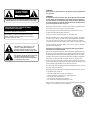
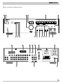
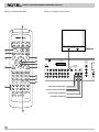
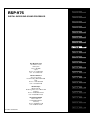
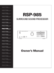
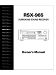
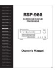
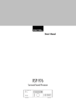
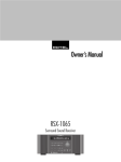
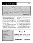
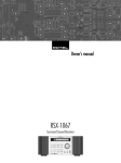
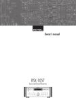
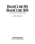
RSP-975
DIGITAL SURROUND
SOUND PROCESSOR
DIGITAL SURROUND SOUND PROCESSOR RSP-975
LISTENING
MASTER VOLUME
STANDBY
CD
TUNER
OPTICAL
COAX 1
TAPE
AUX
DVD
VIDEO 1
VIDEO 2
VIDEO 3
MUTE
PEAK
REMOTE
dB
DIGITAL INPUT
COAX 2
ANALOG INPUT
DVD
DIGITAL
LOCK
REMOTE
SENSOR
DIGITAL
INPUT
DYNAMIC
RANGE
DOLBY
DIGITAL
5.1 CH
SURROUND
MODE
INPUT LEVEL
DOLBY
PROLOGIC
BASS
Owner‘s Manual
STEREO
TREBLE
CAUTION
RISK OF ELECTRIC SHOCK
DO NOT OPEN
WARNING:
There are no user serviceable parts inside. Refer all servicing to qualified service personnel.
CAUTION: TO REDUCE THE RISK OF ELECTRIC SHOCK, DO
NOT REMOVE COVER. NO USER-SERVICEABLE PARTS INSIDE.
REFER SERVICING TO QUALIFIED SERVICE PERSONNEL.
WARNING:
To reduce the risk of fire or electric shock, do not expose the unit to moisture
or water. Do not allow foreign objects to get into the enclosure. If the unit is
exposed to moisture, or a foreign object gets into the enclosure, immediately
disconnect the power cord from the wall. Take the unit to a qualified service
person for inspection and necessary repairs.
APPLICABLE FOR USA, CANADA OR WHERE
APPROVED FOR THE USAGE
Read all the instructions before connecting or operating the component. Keep
this manual so you can refer to these safety instructions.
CAUTION: TO PREVENT ELECTRIC SHOCK, MATCH WIDE BLADE
OF PLUG TO WIDE SLOT. INSERT FULLY.
Heed all warnings and safety information in these instructions and on the
product itself. Follow all operating instructions.
ATTENTION: POUR EVITER LES CHOCS ELECTRIQUES,
INTRODUIRE LA LAME LA PLUS LARGE DE LA FICHE
DANS LA BORNE CORRESPONDANTE DE LA PRISE ET
POUSSER JUSQU AU FOND.
This symbol is to alert the user to the
presence of uninsulated dangerous
voltages inside the product's enclosure
that may constitute a risk of electric shock.
This symbol is to alert the user to important
operating and maintenance (service)
instructions in this manual and literature
accompanying the product.
Clean the enclosure only with a dry cloth or a vacuum cleaner.
Keep the ventilation inlets on the unit unobstructed. For example, do not place
the unit on a bed, sofa, rug, or similar surface that could block the ventilation
slots. If the unit is placed in a bookcase or cabinet, there must be sufficient
clearance around the unit and ventilation of the cabinet to allow proper cooling.
Keep the component away from radiators, heat registers, stoves, or any other
appliance that produces heat.
The unit must be connected to a power supply only of the type and voltage
specified on the rear panel of the unit.
Connect the component to the power outlet only with the supplied power supply cable or an exact equivalent. Do not modify the supplied cable in any way.
Do not attempt to defeat grounding and/or polarization provisions. The cable
should be connected to a 2-pin polarized wall outlet, matching the wide blade
of the plug to the wide slot of the receptacle. Do not use extension cords.
Do not route the power cord where it will be crushed, pinched, bent at severe
angles, exposed to heat, or damaged in any way. Pay particular attention to the
power cord at the plug and where it exits the back of the unit.
The power cord should be unplugged from the wall outlet if the unit is to be left
unused for a long period of time.
Immediately stop using the component and have it inspected and/or serviced
by a qualified service agency if:
•
•
•
•
•
The power supply cord or plug has been damaged.
Objects have fallen or liquid has been spilled into the unit.
The unit has been exposed to rain.
The unit shows signs of improper operation
The unit has been dropped or damaged in any way
Place the unit on a fixed, level surface strong enough to support its weight. Do
not place it on a moveable cart that could tip over.
RSP-975
Figure 1: Controls and Connections
1
2
3
5
4
6
DIGITAL SURROUND SOUND PROCESSOR RSP-975
LISTENING
MASTER VOLUME
CD
TUNER
OPTICAL
COAX 1
STANDBY
AUX
TAPE
DVD
VIDEO 1
VIDEO 2
VIDEO 3
MUTE
PEAK
dB
REMOTE
DIGITAL INPUT
ANALOG INPUT
DVD
COAX 2
DYNAMIC
RANGE
DIGITAL
LOCK
REMOTE
SENSOR
DIGITAL
INPUT
7
8
9
10
11 12
20
19
21
5.1 CH
SURROUND
MODE
13
14
OPTICAL
SMALL
NONE
LARGE
SMALL
LARGE
SUB
SMALL
LARGE
ON
OFF
REMOTE
MONITOR EXTERNAL
TV
IN
CD
TAPE
AUX
DVD
VIDEO 1
VIDEO 2
18
DIGITAL SURROUND SOUND
PROCESSOR
MODEL NO. RSP-975
POWER CONSUMPTION: 30W
VIDEO 3
RSP-975
COAXIAL
NSTC
PAL
TUNER
17
TREBLE
25
SPEAKER CONFIGURATION
REAR
16
STEREO
DIGITAL
INPUT
5.1 CH INPUT
CENTER FRONT
INPUT LEVEL
15
DOLBY
PROLOGIC
BASS
24
23
22
DOLBY
DIGITAL
1
FRONT REAR CENTER
2
L
SWITCHED 800W MAX
CAUTION
RISK OF ELECTRIC SHOCK
DO NOT OPEN
AVIS: RISQUE DE CHOC ELECTRIQUE–NE PAS OUVRIR
POWER
DVD
R
WARNING:TO REDUCE THE RISK OF FIRE
IN
OUT
IN
OUT
IN
OUT
IN
SUB
OUT
OR ELECTRICAL SHOCK, DO NOT EXPOSE
THIS EQUIPMENT TO RAIN OR MOISTURE.
OUTPUT
26
27
28
3
DIGITAL SURROUND SOUND PROCESSOR RSP-975
Figure 2: Remote Control
Figure 3: Output Connections
29
AUD
CD
TAPE
AUX
SAT
TV
VCR
CBL
COMPOSITE
30
TV MONITOR
POWER
VOL
BAND
31
MUTE
CH
T/V
SURROUND +
ON SCREEN
GUIDE
32
MENU
PAUSE
C. DELAY
SEARCH –
SEARCH +
TRACK –
PLAY
SEL
35
TRACK +
36
DOWN
STOP
DYNAMIC
PRE
CH
RECALL
OPN/CLS
DIGITAL
INPUT
5.1 CH INPUT
37
UP
33
S-VIDEO
VIDEO INPUT
OPTICAL
38
SUB
ALL
GE
ON
OFF
1
2
3
MOVIE FILT
DISC 2
DISC 3
PROG
M
POW
REMOTE
MONITOR EXTERNAL
TV
IN
COAXIAL
NSTC
PAL
SUR DELAY
DISC 1
DIGI
RATION
AR
AUX
DVD
VIDEO 1
VIDEO 2
VIDEO 3
1
FRONT REAR CENTER
2
AVIS: RI
4
5
6
5.1
DISC 4
DISC 5
DISC 6
TIME [REVIEW]
7
8
9
SELECT
39
DVD
WARN
40
UT
IN
OUT
IN
OUT
IN
10
0
ENTER
BACK
OUT BAL
BAL CHK
>10
34
CD
TUNER
AUX 1
AUX 2
PHONO/LD
TAPE 1
TAPE 2
VIDEO 1
VIDEO 2
VIDEO 3
M1
M2
M3
41
To front channel amplifier inputs
To surround channel amplifier inputs
M4
To center channel amplifier input
[SHIFT]
LIGHT
To subwoofer amplifier input
RR-939
42
24
SUB
OUT
OUTPUT
DIGITAL IN
OR ELEC
THIS EQ
RSP-975
Figure 4: Input Connections
DVD PLAYER
AUDIO OUTPUT
VIDEO OUTPUT
COAX
OPTI
S-VIDEO
LEFT
DIGITAL
OUT
COMPOSITE
RIGHT
DTS DECODER
FRONT
REAR
DIGITAL
L
IN
CENTER
IN
OPTI
INPUT
OUT
COAX
OUTPUT
5.1 CH
R
SUBWOOFER
ROTEL RSP-975
DIGITAL
INPUT
5.1 CH INPUT
OPTICAL
DIGITAL SURROUND SOUND
PROCESSOR
MODEL NO. RSP-975
POWER CONSUMPTION: 30W
SPEAKER CONFIGURATION
CENTER FRONT
SMALL
NONE
LARGE
SMALL
LARGE
REAR
SUB
SMALL
LARGE
ON
OFF
REMOTE
MONITOR EXTERNAL
TV
IN
TUNER
CD
TAPE
AUX
DVD
VIDEO 1
VIDEO 2
VIDEO 3
RSP-975
COAXIAL
NSTC
PAL
1
FRONT REAR CENTER
2
SWITCHED 800W MAX
CAUTION
L
POWER
DVD
R
IN
OUT
IN
OUT
IN
OUT
IN
SUB
OUT
OUTPUT
VIDEO RECORDER
AUDIO OUTPUT
VIDEO OUTPUT
LEFT
RIGHT
AUDIO INPUT
S-VIDEO
COMPOSITE
VIDEO INPUT
LEFT
RIGHT
S-VIDEO
COMPOSITE
AM/FM TUNER
AUDIO OUTPUT
LEFT
RIGHT
5
DIGITAL SURROUND SOUND PROCESSOR RSP-975
○ ○ ○ ○ ○ ○ ○ ○ ○ ○ ○ ○ ○ ○ ○ ○ ○ ○ ○ ○ ○ ○ ○ ○ ○ ○ ○ ○ ○ ○ ○ ○ ○
Contents
Figure 1: Controls and Connections
3
Figure 2: Remote Control
4
MAIN Screen
12
Figure 3: Output Connections
4
OUTPUT BALANCE Screen
12
Figure 4: Input Connections
5
About Rotel
7
Source Inputs 26
13
Getting Started ______________________________________ 7
Digital Inputs 24
13
13
Rear Panel Input Connections ________________________ 13
RSP-975 Key Features
7
5.1 CH INPUT 20
Unpacking the RSP-975
7
REMOTE EXTERNAL IN Jack
Placement
7
STANDBY Switch 1
30 and STANDBY LED
2
Remote Sensor 7
MASTER VOLUME Control 3
29
22
13
Rear Panel Output Connections ______________________ 13
Source Outputs 26
14
7
Main Audio Outputs 27
14
8
MONITOR TV Output 21
14
Front Panel Controls __________________________________ 7
8
Rear Panel Configuration Switches ___________________ 14
VOLUME Display 4
8
NTSC/PAL Video Switch 23
14
TONE Controls 18
8
SPEAKER CONFIGURATION Switches 19
14
LISTENING SOURCE Buttons 5
34
8
Rear Panel AC Power Connections ____________________ 15
DIGITAL INPUT Button 12 40 / INPUT LEDs 15
8
AC Power cord 28
15
5.1 CH Button 13 39
8
AC Outlets 25
15
SURROUND MODE LEDs 17
8
SURROUND MODE Button 14 32
9
INPUT LEVEL Buttons 16
9
MUTE LED 10
9
PEAK LED 9
9
REMOTE LED 8
9
DYNAMIC RANGE LED 6
9
DIGITAL LOCK LED 11
9
RR-939 Remote Control _______________________________ 9
6
The On-Screen Display _______________________________ 12
Programming the RR-939
10
POWER Switch 30
10
MASTER VOLUME Controls 29
10
SELECTOR Buttons 34
10
5.1 Button 39
10
MUTE Button (remote only) 31
10
SELECT Button (Digital Input) 40
10
SURROUND + Button 32
10
SURROUND DELAY Button (remote only) 38
10
CENTER DELAY Button (remote only) 36
11
DYNAMIC Button (remote only) 37
11
BACK/BALANCE CHECK (remote only) 41
11
ENTER/OUTPUT BALANCE (remote only) 42
11
RECALL Button 33
11
ON-SCREEN Button (remote only) 35
11
RSP-975 Specifications ______________________________ 15
RSP-975
○ ○ ○ ○ ○ ○ ○ ○ ○ ○ ○ ○ ○ ○ ○ ○ ○ ○ ○ ○ ○ ○ ○ ○ ○ ○ ○ ○ ○ ○ ○ ○ ○
About Rotel
A family whose passionate interest in music led them to manufacture high fidelity components of uncompromising quality founded
Rotel over 30 years ago. Through the years that passion has remained undiminished and the family goal of providing exceptional
value for audiophiles and music lovers regardless of their budget,
is shared by all Rotel employees.
The engineers work as a close team, listening to, and fine tuning
each new product until it reaches their exacting musical standards. They are free to choose components from around the world
in order to make that product the best they can. You are likely to
find capacitors from the United Kingdom and Germany, semi conductors from Japan or the United States, while toroidal power
transformers are manufactured in Rotel’s own factory.
Rotel’s reputation for excellence has been earned through hundreds of good reviews and awards from the most respected reviewers in the industry, who listen to music every day. Their
comments keep the company true to its goal - the pursuit of
equipment that is musical, reliable and affordable.
All of us at Rotel, thank you for buying this product and hope it will
bring you many hours of enjoyment.
○ ○ ○ ○ ○ ○ ○ ○ ○ ○ ○ ○ ○ ○ ○ ○ ○ ○ ○ ○ ○ ○ ○ ○ ○ ○ ○ ○ ○ ○ ○ ○ ○
Getting Started
Thank you for purchasing our RSP-975 Digital Surround Sound
Processor. The RSP-975 is a full-featured audio/video processor
designed to decode both analog and digital surround sound signals including Dolby Pro Logic and 5.1 channel Dolby Digital
sources. It will provide accurate reproduction of both movie
soundtracks and demanding musical selections and is a natural
extension of our well-known passion for good sound.
To get the most from your RSP-975, we suggest you read this
manual and keep it as a reference to answer any future questions.
RSP-975 Key Features
•
Rotel’s “Balanced Design” approach combines advanced circuit
board layout, comprehensive parts evaluation, and extensive listening tests for superior sound and long term reliability.
•
Dolby® Pro Logic® decoding for analog sources
•
Dolby Digital® decoding for 5.1 channel digital sources
•
5.1 channel input for DTS® adaptor and/or future upgradeabilty
•
User friendly operation with On-Screen Display.
•
Comprehensive digital and analog input and output connections
for audio and video sources.
Unpacking the RSP-975
Your RSP-975 underwent quality control tests before we sent it on
its way to you and should perform perfectly out of the box.
Remove the unit carefully from its packing. Look for the handheld
remote controller and other accessories. Save the packing and
box if possible as it will protect the RSP-975 if you move or need to
return it to us for maintenance.
Placement
Place the RSP-975 on a solid, dry, level surface away from direct
sunlight, excessive heat, high humidity, or strong vibrations.
Make sure the RSP-975 is close to the other components in your
audio/video system as that makes initial hookup and any subsequent troubleshooting easier.
If at all possible, put the RSP-975 on its own shelf. This makes initial cable routing, hookup, and any subsequent system changes
easier. It also minimizes potential interference or heat buildup
from other components.
Make sure there is enough room behind the RSP-975 for easy
hookup. Remember, you’re connecting many other components to
this unit and you’ll probably need more space than you think.
Don’t stack other objects (components or other items) on top of
the RSP-975. Don’t let water fall into the RSP-975 as this could
damage delicate circuitry.
○ ○ ○ ○ ○ ○ ○ ○ ○ ○ ○ ○ ○ ○ ○ ○ ○ ○ ○ ○ ○ ○ ○ ○ ○ ○ ○ ○ ○ ○ ○ ○ ○
Front Panel Controls
We suggest you look over the RSP-975’s front and rear panels before you start connecting other components to it. The following
explanations will help you get familiar with the units connections,
features, and controls, with number references corresponding to
the illustrations at the front of this manual.
Most functions are duplicated on the front panel and on the
handheld remote control shipped with your unit. A few may be
available only on one or the other. When two reference numbers
appear, one refers to the location of the button on the front panel,
the other to the location of the button on the handheld remote
control.
STANDBY Switch
1
30
and STANDBY LED
2
The RSP-975 is similar to many TV sets in that some of its circuitry
(the central microprocessor, infrared sensor, etc.) remains powered at all times while the rest of the circuitry is turned on or off
by the user.
The STANDBY switch turns the RSP-975 from standby mode to
fully active mode. If only the STANDBY LED is lit, the unit is in
standby mode.
7
DIGITAL SURROUND SOUND PROCESSOR RSP-975
The DIGITAL INPUT button allows you select one of these digital
inputs to use in place of the ANALOG INPUT for each LISTENING
SOURCE SELECT button. For example, if you have a DVD player ,
you can connect the DVD player’s digital output to the DVD DIGITAL INPUT and then tell the RSP-975 to use the digital signal in
place of the analog signal.
Push the front panel STANDBY button (or the handheld remote
POWER button) to fully activate the RSP-975. You'll see other LEDs
light up and the STANDBY LED will go out. Push the STANDBY
switch again to deactivate the RSP-975.
Note: The STANDBY switch controls the rear panel AC outlet.
When the RSP-975 is in standby mode the AC outlet is also off.
When the RSP-975 is fully functional, the AC outlet is live.
Remote Sensor
7
This sensor receives infrared signals from the handheld remote
control. Make sure you do not accidentally block this sensor with
cables or accessories.
MASTER VOLUME Control
3
To select a DIGITAL or ANALOG input for a given LISTENING
SOURCE input:
•
Select the desired LISTENING SOURCE input.
•
Repeatedly press the DIGITAL INPUT button to sequentially step
through the available digital inputs (OPTICAL/COAX1/COAX2/DVD/
ANALOG). Stop when the desired INPUT LED lights.
29
The MASTER VOLUME knob is an electronic rotating control. Turn
it clockwise to increase the volume; counterclockwise to decrease. MASTER VOLUME buttons are also available on the
RSP-975's handheld remote control.
NOTE: The DIGITAL or ANALOG INPUT is immediately memorized
as it is selected and will be automatically activated when you select that LISTENING SOURCE SELECTOR button in the future.
5.1 CH Button
VOLUME Display
As you adjust the volume, a digital display located above the control will provide a volume indication in one decibel steps with
+12dB being maximum output level and –67dB being minimum.
TONE Controls
18
BASS and TREBLE controls increase and decrease the audio
signal’s low and high frequency content. Rotate each one clockwise to increase output in the respective frequency range and
counterclockwise to reduce it. The center detent removes each
control from the audio path for maximum signal integrity.
LISTENING SOURCE Buttons
5
34
Eight large front panel LISTENING buttons allow you to select an
audio or video source component such as CD, TUNER, VCR, DVD,
etc. Simply push any of these buttons to select an input source.
(The handheld remote has functionally identical buttons.) You will
hear this source and, if you have selected a video source, see its
picture on your TV monitor. An LED indicator on each pushbutton
lights to confirm your selection.
Note: As delivered from the factory, pushing one of these buttons
activates the analog audio inputs for each component. However,
to accommodate digital signals available from many source components (such as CD players and Dolby Digital DVD players), the
RSP-975 also provides four digital inputs which may be used instead. See below.)
DIGITAL INPUT Button
12
40
/ INPUT LEDs
15
In addition to analog audio inputs for each of eight source components, the RSP-975 provides DIGITAL INPUTS for up to four digital
audio sources. These four DIGITAL INPUTS can be assigned to
any of the eight LISTENING inputs
8
13
39
4
This button overrides all other input selectors (both analog and
digital) and directly connects an external adaptor (such as Rotel’s
RDA-986 DTS Processor) to the RSP-975’s MASTER VOLUME control. This allows the RSP-975 to remain the central controller for
even the most advanced audio/video systems. When activated, all
of the RSP-975’s inboard Dolby processing is bypassed.
SURROUND MODE LEDs
17
The RSP-975 provides three different surround sound modes to
accommodate different types of audio and video source material
as described below. These LEDs tell you which surround sound
mode you’ve selected. Here is a brief description of the various
surround modes.
STEREO is a conventional 2-speaker stereo direct bypass mode
with no surround sound or other processing. The FRONT LEFT
speaker, the FRONT RIGHT speaker, and the SUBWOOFER (if
present) are on; all other speakers are off.
DOLBY DIGITAL provides proper playback decoding processing
for any discrete 5.1 channel Dolby Digital encoded digital audio
source such as an AC-3 Laser Disc or DVD disc. Dolby Digital provides the highest level of surround sound performance with 5
channels of discrete surround information plus subwoofer. Dolby
Digital is only available when using one of the DIGITAL inputs. It is
not available for ANALOG inputs.
DOLBY PRO LOGIC provides proper playback decoding and processing for any Dolby Surround encoded analog audio source,
whether it be a music CD, videotape, videodisc, conventional stereo TV broadcast, or satellite broadcast. Dolby Pro Logic processing and playback through a properly calibrated system will
preserve the directionality, ambiance, and spatial effects intended
by the source’s producers. Dolby Pro Logic can also provide excellent surround sound playback of musical recordings.
RSP-975
SURROUND MODE Button
14
32
The SURROUND MODE button is used to select one of three surround modes (Dolby Pro Logic, Dolby Digital, or Stereo) as described in the section immediately above. To make a selection,
press the SURROUND MODE button. Each time you press the button, the mode will cycle to the next available setting as indicated
by the SURROUND MODE LEDs.
PEAK LED
9
This front-panel LED lights to indicate that the input signal of the
selected source may be overloading the input circuitry of the
RSP-975. Momentary occasional flashes of this LED on signal
peaks are acceptable. However, if the LED repeatedly or continuously lights, you should reduce the input level for that source.
REMOTE LED
NOTE: If an ANALOG input is selected, the only available surround
mode options are DOLBY PRO LOGIC and STEREO. All three options are available for DIGITAL inputs.
The surround mode selection for ANALOG inputs (STEREO or
DOLBY PRO LOGIC) is memorized as soon as it is made for each
LISTENING INPUT and will be automatically engaged the next
time that LISTENING INPUT is selected.
The surround mode setting for DIGITAL INPUTS is not memorized
and is only a temporary override as long as that LISTENING INPUT
is activated.
Every time a DIGITAL INPUT is selected, the surround mode setting will default to DOLBY DIGITAL. If a digital signal is detected
that is not DOLBY DIGITAL, the mode will automatically switch to
DOLBY PRO LOGIC. [???? Is this auto-sensing in the RSP-975?]
INPUT LEVEL Buttons
16
These two pushbuttons allow you to adjust the level of each
source component so that the volume level remains relatively
constant when switching between source components.
NOTE: The INPUT LEVEL adjustments only effect the ANALOG input for each source. They have no effect on the DIGITAL inputs.
To reduce the input level of the selected source, press the INPUT
LEVEL < button. To increase the level of the selected source press
the INPUT LEVEL > button. As the setting is adjusted, the VOLUME
DISPLAY changes to show the INPUT LEVEL. The range of the adjustment is from 0dB (full gain) to –12dB.
The setting is memorized as soon as it is made so that it will automatically be recalled whenever that source component is selected.
Note: For optimum performance, it is important not to set the
source input levels so high that the signal overloads the RSP-975’s
input circuitry. If the PEAK LED on the front panel is repeatedly
flashing, adjust the input level for that source downward.
MUTE LED
8
This front-panel LED lights to indicate that a command is being received from the handheld remote control.
DYNAMIC RANGE LED
6
Today’s digital sources are capable of extremely high dynamic
range (the difference between the softest and loudest sounds). In
some cases, the available dynamic range may tax the amplifiers
or speakers. In other cases, it may be desirable to reduce the dynamic range, for example, when listening at low volume levels.
The RSP-975 provides the capability to reduce the dynamic range
in three progressive steps (25% / 50% / 75% reduction) with a
pushbutton on the handheld remote control. See the Remote Control section of this manual for details.
This front-panel LED lights to indicate that the dynamic range has
been reduced.
DIGITAL LOCK LED
11
The RSP-975 digital circuitry can lock onto digital signals with a
number of different sampling rates. The DIGITAL LOCK LED lights
to indicate that the digital circuitry has recognized and locked
onto a digital signal.
○ ○ ○ ○ ○ ○ ○ ○ ○ ○ ○ ○ ○ ○ ○ ○ ○ ○ ○ ○ ○ ○ ○ ○ ○ ○ ○ ○ ○ ○ ○ ○ ○
RR-939 Remote Control
The RSP-975 includes a handheld remote control that does far
more than operate the RSP-975. The RR-939 is a full-function programmable remote control that can operate 8 A/V components.
A separate manual, included with the remote, gives detailed information on programming and using the RR-939 to replace all of the
remote controls in your system. This section is intended to provide
only that information which pertains to the use of the RR-939 to
operate the RSP-975.
Note: Many functions duplicate the RSP-975 front panel controls
and are listed here only for your reference. Please refer to the
previous Front Panel Controls section of this manual if you need
additional information.
10
This front-panel LED lights to indicate that the output of the
RSP-975 has been muted from handheld remote control.
To operate the RSP-975 with the remote, make sure that the AUDIO mode is active by pressing the AUD button on the remote before you start. If it is active, pressing command keys on the RR-939
will cause the AUDIO button to flash red. Once the AUDIO mode is
active, it will stay active unless you press one of the other DEVICE
buttons to control a different component.
9
DIGITAL SURROUND SOUND PROCESSOR RSP-975
Programming the RR-939
SELECT Button (Digital Input)
The RR-939 is preprogrammed from the factory to operate the
RSP-975. Should the AUDIO command set on your RR-939 not operate the RSP-975, it’s possible that the programming had been inadvertently changed. To reprogram the remote to operate the
RSP-975:
1. Press the AUDIO button at the top of the remote while simultaneously pressing the MUTE button and hold both for at least one
second. The AUDIO button will light in red for 20 seconds, indicating that you have entered the program mode. The next step must
be done within this 20 second period, or the RR-939 will revert to
its standard operating mode.
2. Use the NUMERIC buttons to enter the 3-digit code (001) for the
RSP-975 – press 0, then 0, then 1. The AUDIO button will flash
each time you enter a digit.
3. Store the code number by pressing the corresponding AUDIO
button again. The button will blink twice to confirm the storage of
the code in memory.
POWER Switch
30
Duplicates the function of the Standby Switch on the front panel.
Press to activate the RSP-975. Press again to deactivate.
MASTER VOLUME Controls
The VOLUME UP/DOWN buttons are also used in making certain
system configuration settings.
34
A group of ten buttons which duplicate the function of the LISTENING SOURCE SELECTOR buttons on the RSP-975 front panel.
Select any input source by pressing the appropriate button.
The labels on the remote buttons match the front panel buttons,
except that the button labelled PHONO/LD corresponds to the
front panel DVD input button and the button labelled AUX 1 corresponds to the front panel AUX input button. The remote buttons labelled AUX 2 and TAPE 2 are not used with the RSP-975.
5.1 Button
Duplicates the 5.1 CH button on the front panel. Selects the 5.1
Channel input, overriding any other sources.
31
Push this button once to reduce the output levels to zero – to turn
the sound off. The front panel MUTE LED will light. Press the
MUTE button again to restore the prior volume level.
10
SURROUND + Button
32
Duplicates the function of the front-panel SURROUND MODE button. Steps sequentially through various surround sound operating
modes. Your current selection will be indicated by front panel
LEDs and will be memorized for ANALOG inputs.
SURROUND DELAY Button (remote only)
38
The surround processing in the RSP-975 delays the signal sent to
the rear surround speakers as a means of simulating a larger
physical space (such as a movie theater or concert hall) and to
ensure that sounds from the front speakers reach your ear first.
The SURROUND DELAY button steps sequentially through four
available settings for your selected surround mode (not applicable
in STEREO modes).
NOTE: The SURROUND DELAY setting is system-wide. Changing it
will increase or decrease the relative delay time for all inputs and
both surround modes. The setting is automatically memorized as it
is made.
You will get visual confirmation of your delay time setting on the
VOLUME DISPLAY as you adjust the setting. The delay time setting
also appears in the ON-SCREEN DISPLAY (see below).
There are no hard and fast rules for setting proper delay times.
Many listeners will be satisfied with the default settings. Others
will want to experiment. In the end, it is a matter of personal taste.
In general, longer delay time settings will tend to create the illusion of a larger acoustic space, although if overdone, the effect
can be exaggerated and unnatural. Longer delay settings may
typically be more spectacular. Shorter delay times may be more
natural.
Delay times also may need to be adjusted depending on the relative distance from the listening position to the front and rear
speakers. As a general rule, your attention should never be drawn
to the surround speakers as a primary sound source, particularly
when listening to music. If you are closer to the rear speakers, increasing the delay time may prevent this problem.
The four DELAY TIME choices for each surround mode are:
39
MUTE Button (remote only)
Duplicates the DIGITAL INPUT button on the front panel. Selects
the ANALOG input or one of the DIGITAL inputs for the currently
selected source.
29
A pair of buttons which duplicate the function of the front panel
volume control. Press VOLUME DOWN to reduce the volume and
press VOLUME UP to increase the volume.
SELECTOR Buttons
40
STEREO:
DOLBY PRO LOGIC:
DOLBY DIGITAL:
STEP 1
NONE
15 ms
NONE
STEP 2
NONE
20 ms
5 ms
STEP 3
NONE
25 ms
10 ms
STEP 4
NONE
30 ms
15 ms
Again, experimentation will show you which settings are best for
your source material, room conditions, and system setup.
RSP-975
CENTER DELAY Button (remote only)
36
The CENTER DELAY button works like the SURROUND DELAY button above, except that it increases the delay the center channel
speaker, if present. CENTER DELAY is only available in Dolby
Digital surround mode. The CENTER DELAY button steps sequentially through five available settings (O, 1, 2, 3, 4, 5 ms).
NOTE: The CENTER DELAY setting is system-wide. Changing it will
increase or decrease the relative delay time for all inputs in Dolby
Digital surround mode. The setting is automatically memorized as
it is made.
You will get visual confirmation of your delay time setting on the
VOLUME DISPLAY as you adjust the setting. The delay time setting
also appears in the ON-SCREEN DISPLAY (see below).
DYNAMIC Button (remote only)
37
This button is used to reduce the dynamic range to accommodate
program material that could tax your system or for low-volume listening. This feature is only available in Dolby Digital surround
mode.
Press the button repeatedly to step through the four available settings: NONE (full dynamic range), 25% reduction, 50% reduction,
and 75% reduction. While making the adjustment, the setting will
appear in the VOLUME display. The setting is also shown in the
ON-SCREEN DISPLAY (see below).
A front-panel LED lights to indicate that the dynamic range has
been reduced.
BACK/BALANCE CHECK (remote only)
41
The BACK button on the remote control is used during initial calibration of relative speaker volume levels. Generally, it is only used
during initial setup of the system and not during normal operation.
To enter the BALANCE CHECK calibration, press and hold the
BACK button for 2 seconds. The following screen will appear on
your TV monitor, for adjusting the relative volume levels of the
front, center, and rear speakers, along with the subwoofer.
will disappear after all six speakers have been highlighted and
you may need to re-enter the menu by pressing and holding the
BACK button.
While seated in the normal listening location, switch the test tone
to the various speakers and listen to hear if any are noticeably
louder or quieter than the front speakers. If so, adjust the quieter
speakers volume levels up or down to match the louder speakers
using the VOL UP/DOWN remote buttons, while the speaker you
wish to adjust is highlighted. Continue switching among the
speakers and adjusting until all of the speakers are approximately
the same volume (or to suit your listening preference).
This setting will be memorized when you leave the menu and will
become the system-wide default setting.
ENTER/OUTPUT BALANCE (remote only)
42
The ENTER button on the remote control has a similar function to
the BALANCE CHECK calibration described above, except that its
adjustments are temporary and apply only to the selected source
input. As soon as you select a different source, the settings revert
to the system-wide defaults as set during the BALANCE CHECK
calibration.
NOTE: Although these adjustments can be made directly using the
ENTER button, we strongly recommend that you only make these
adjustments from the ON-SCREEN DISPLAY system. For this reason, the instructions are included in the section on the ONSCREEN DISPLAY (see below).
RECALL Button
33
You can temporarily reset the OUTPUT BALANCE settings to 0dB
for all speakers at any time by pressing the RECALL button on the
remote control. The memorized sytem-wide settings will be activated when you switch to a different LISTENING SOURCE input.
ON-SCREEN Button (remote only)
35
Push this button to turn on the ON-SCREEN DISPLAY. If the ONSCREEN DISPLAY is already visible, push this button once or twice
to cancel the display. See next section for details.
BALANCE CHK
L/F
0dB
CEN
0dB
R/F
0dB
S/L
0dB
SUB
0dB
S/R
0dB
When the menu appears, the L/F speaker label will be flashing and
you will hear a test tone coming from that speaker. You can select
the other speakers by sequentially pressing the BACK button. The
test tone will shift accordingly to the selected speaker. The menu
11
DIGITAL SURROUND SOUND PROCESSOR RSP-975
○ ○ ○ ○ ○ ○ ○ ○ ○ ○ ○ ○ ○ ○ ○ ○ ○ ○ ○ ○ ○ ○ ○ ○ ○ ○ ○ ○ ○ ○ ○ ○ ○
The On-Screen Display
The RSP-975 features two ON-SCREEN DISPLAY screens to help
operate the system. These screens are available at any time by
pressing the ON-SCREEN MENU button on the remote control to
activate the first screen. Push the button a second time to go to
the second screen (OUTPUT BALANCE). Push the button a third
time to cancel the ON-SCREEN DISPLAY.
MAIN Screen
INPUT:
S MODE:
C DELAY:
S DELAY:
DYNAMIC:
VIDEO 1
COAX 1
DOLBY DIGITAL
5ms
15ms
NONE
VOLUME: –40db
––––––––––––––––––––––––––––
The MAIN menu provides status information and configuration options for the source inputs and other system parameters. Some of
the items shown above will not be available for all surround
modes. For example, C DELAY and DYNAMIC will only appear in
DOLBY DIGITAL mode.
INPUT: Two lines showing the currently selected input source and
the audio input for that source. Change the source using the LISTENING SOURCE SELECT buttons on the front panel or remote.
Change the audio input using the DIGITAL INPUT button on the
front panel or the SELECT button on the remote.
S MODE: The currently selected surround mode. Change using the
SURROUND MODE front panel button or the SURROUND + button
on the remote.
C DELAY: The current center channel delay setting, only shown in
Dolby Digital surround mode. Adjust using the C DELAY button on
the remote.
S DELAY: The current surround delay setting, only shown in Dolby
Digital and Dolby Pro Logic surround modes. Adjust using the SUR
DELAY button on the remote.
DYNAMIC: The dynamic range setting, only shown in Dolby Digital
surround mode. Adjust using the DYNAMIC button on the remote.
5.1 CH INPUT: whether or not the 5.1 channel input is active
VOLUME: Duplicates the front panel VOLUME display, along with a
bar graph volume indication. Adjust using the VOLUME controls
on the front panel or remote.
Press the ON-SCREEN MENU button a second time to go to the
next screen:
OUTPUT BALANCE Screen
OUTPUT BAL
L/F
0dB
CEN
0dB
R/F
0dB
S/L
0dB
SUB
0dB
S/R
0dB
INPUT
0dB
S MONO
The OUTPUT BALANCE screen provides a temporary adjustment
to the relative output levels of each speaker in the system. Unlike
the BALANCE CHECK calibration procedure, the changes made on
this screen are temporary. They change the output balance only
for the current source input and only until a different source is selected, when the settings will revert to the system-wide default
established during the BALANCE CHECK calibration.
SPEAKER OUTPUT LEVELS: The main portion of the screen consists of labels for each of the speakers in the system, along with
an output level setting. The screen above shows ALL possible
speakers as would appear in a full system in Dolby Pro Logic
mode. Depending on your system configuration and surround
mode setting, you will see a smaller complement of speakers. For
example, in STEREO mode, you will only see FRONT speakers (and
the SUBWOOFER, if your system is configured for a subwoofer).
To adjust the output of your speakers:
1. Press the ENTER button on the remote. The first speaker label will
flash. Adjust its output level up or down with the VOLUME controls
on the front panel or remote.
2. Press the ENTER button on the remote again to move to the next
speaker. Adjust its output level, and press the ENTER button again
to continue the process until all speakers have been adjusted.
3. Press the ENTER button on the remote again to move to the next
speaker. Adjust its output level, and press the ENTER button again
to continue the process until all speakers have been adjusted.
4. Once you’ve started adjusting, the screen will return to the MAIN
screen after 5 seconds of inactivity or when you press ENTER after the final speaker.
NOTE: You can reset the temporary OUTPUT BALANCE settings to
0dB for all speakers at any time by pressing the RECALL button on
the remote control.
S MONO: This indication appears in the screen only in DOLBY PRO
LOGIC surround mode to indicate that the surround speakers reproduce a mono signal in this mode.
12
RSP-975
INPUT: This indication appears only when an ANALOG source input is selected. It shows the current INPUT LEVEL setting for the
active source input and can be adjusted with the front panel INPUT LEVEL buttons. This change is not temporary. It is memorized
and will be recalled each time that source input is selected.
○ ○ ○ ○ ○ ○ ○ ○ ○ ○ ○ ○ ○ ○ ○ ○ ○ ○ ○ ○ ○ ○ ○ ○ ○ ○ ○ ○ ○ ○ ○ ○ ○
Rear Panel Input Connections
This section of the manual provides complete information on all of
the audio and video signal input connections on the rear panel of
the RSP-975. For convenience, each topic begins with an overview of the particular connection, followed by detailed hookup instructions.
Note: DO NOT plug any system component into an AC source until
system hookup is complete. Wait to apply power until you’re confident that all component-to-component connections have been
properly made.
All video and digital audio cables should have a 75 ohm impedance rating. Because the video and digital cable standards are as
close as they are, you can safely use a video cable for digital audio data transmission and, conversely, a digital audio cable for
video data transmission. We strongly advise that you NOT substitute a conventional analog audio interconnect cable for either
digital or video.
Source Inputs
26
These eight sets of RCA-type inputs (TUNER, CD, TAPE, AUX, DVD,
VIDEO 1, VIDEO 2, and VIDEO 3) accept line level audio and composite video signals from source components. The first four inputs
are audio-only, the other four source inputs accept both left and
right channel audio plus a video signal.
All RCA-type connections on the RSP-975 follow these standard
color codes:
Left channel audio =
Right channel audio =
Composite video
=
RCA jack with white inset
RCA jack with red inset
RCA jack with yellow inset
Connect the OUTPUTS of your source components to the appropriate INPUTS on the RSP-975. For example, if your system includes a CD player, connect its left and right channel analog
outputs to the RSP-975’s CD inputs. If your system includes a video
source, connect its analog audio outputs to one of the RSP-975’s
VIDEO audio inputs and its video composite RCA output to the corresponding composite RCA video input.
Digital Inputs
24
The RSP-975 features a D/A conversion capability which allows it
to accept digital input signals from source components. These include digital signals from CD players, satellite TV receivers, and
5.1 channel Dolby Digital signals from DVD players. The D/A automatically senses and adjusts to the correct sampling rates.
To take full advantage of the built-in digital decoding capability,
the RSP-975 accepts digital signals from up to four different
source components in a number of formats. The digital inputs are
as follows:
OPTICAL: This input allows connection of a standard optical digital output from a CD player or other source component. Requires
an optical digital cable.
COAX 1 and COAX 2: Two standard coaxial digital connectors for
use with the digital output of any component (CD player, Satellite
TV, etc.)
DVD: Standard coax digital connection for use with Dolby Digital
DVD players.
To use the digital inputs, simply connect the appropriate cable
from the digital output of your source component to the corresponding digital input on the RSP-975.
It is necessary to select the appropriate digital (or analog) input
for each component. Once the selection is made, it is memorized
so that simply selecting a SOURCE INPUT activates the appropriate audio input. This procedure is detailed in the DIGITAL INPUT
button section of this manual.
5.1 CH INPUT
20
This 25-pin input connects six discrete channels of analog information from an outboard processor (DTS, for example).
External adaptors may provide both RCA and DB25 outputs. We
suggest that you use a DB25-to-DB25 cable to reduce the number
of cables and to insure proper channel-to-channel continuity.
If your external adaptor does not have a DB25 output, you will
need to purchase a multi-RCA to DB25 adaptor cable from your
Rotel retailer. Make sure to observe proper channel continuity.
REMOTE EXTERNAL IN Jack
22
This 3.5 mm jack accepts a remote infrared sensor which duplicates the function of the front panel IR sensor in installations
where the front panel sensor could be blocked by a cabinet. See
your authorized Rotel dealer for a selection of remote sensors that
will work with your RSP-975.
○ ○ ○ ○ ○ ○ ○ ○ ○ ○ ○ ○ ○ ○ ○ ○ ○ ○ ○ ○ ○ ○ ○ ○ ○ ○ ○ ○ ○ ○ ○ ○ ○
Rear Panel Output Connections
This section of the manual provides complete information on the
audio and video signal output connections on the rear panel of the
RSP-975 which are used for routing the output signals to a television monitor, audio amplifiers, and recording devices. For convenience, each topic begins with an overview of the particular
connection, followed by detailed hookup instructions.
13
DIGITAL SURROUND SOUND PROCESSOR RSP-975
Source Outputs
○ ○ ○ ○ ○ ○ ○ ○ ○ ○ ○ ○ ○ ○ ○ ○ ○ ○ ○ ○ ○ ○ ○ ○ ○ ○ ○ ○ ○ ○ ○ ○ ○
26
Four of the input sources have corresponding sets of RCA output
connections for routing the signal of the RSP-975 to audio or video
tape recorders for recording.
TAPE provides a stereo pair of audio outputs. Connect standard
RCA cables from the LEFT and RIGHT outputs to the LEFT and
RIGHT record inputs on your audio tape recorder.
VIDEO 1, VIDEO 2, AND VIDEO 3 include left and right channel audio plus composite coax video output from the RSP-975 to VCRs or
other components (VCR, etc.) for recording. Standard color coding
applies.
Connect the RSP-975's VIDEO 1 left and right audio outputs to the
audio inputs of the first source component. Then, connect the
VIDEO 1 composite video output to the video input of the same
source component. Repeat these steps for Video 2 and Video 3
connections, if necessary/
Once properly connected, whatever input signal is selected by the
LISTENING INPUT SOURCE buttons is available for recording at
any or all of the output connections.
NOTE: Only analog audio signals are available at the record outputs. Therefore, even if you choose to use digital signals from
your source components, you should also connect their analog
signals to the RSP-975, for recording purposes.
Rear Panel Configuration Switches
The RSP-975 has five switches that must be set according to your
particular system configuration. Details follow:
NTSC/PAL Video Switch
There are two different video standards used in different parts of
the world. In the United States, broadcast TV and video components adhere to the NTSC standard. In Europe, the PAL standard
is more common. These differ in their technical details (scanning
frequency, etc.) and are not interchangeable.
You must set the rear panel switch to match the video standard in
your country. If set incorrectly, the video signal sent to your TV
monitor will be unrecognizable.
SPEAKER CONFIGURATION Switches
SPEAKER CONFIGURATION
CENTER FRONT
Standard color coding applies with black insets to distinguish
center channel and subwoofer outputs from left (white) and right
(red) Front and Rear outputs.
To hook up the RCA main audio outputs, connect a standard audio
cable from each output to the input of the amplifier channel that
will power the corresponding speaker. In a full home theater system, you will need to make six different connections corresponding to the six speakers (LEFT FRONT, CENTER FRONT, RIGHT
FRONT, LEFT SURROUND, RIGHT SURROUND, and SUBWOOFER).
It is important to make sure that you have the correct output connected to the proper amplifier channel. Take your time.
21
The video output of the RSP-975 sends the video signal to your TV
monitor from an RCA-type composite video connection. Simply
connect the MONITOR TV output to a video input on your television monitor, using a standard RCA composite video cable. Whatever signal is selected on the RSP-975 will appear on screen.
14
SMALL
LARGE
REAR
SUB
SMALL
LARGE
ON
OFF
27
These six outputs (LEFT FRONT, CENTER FRONT, RIGHT FRONT,
LEFT SURROUND, RIGHT SURROUND, and SUBWOOFER) connect
the RSP-975's main audio output to a multichannel power amplifier or multiple power amplifiers for the primary listening area via
six individual RCA-style jacks.
MONITOR TV Output
19
There are four speaker configuration switches on the RSP-975’s
rear panel — CENTER (small/none/large), FRONT (small/large),
REAR (small/large), and SUB (on/off). These switches let you customize the RSP-975’s main outputs to precisely match system configuration and speaker capabilities.
SMALL
NONE
LARGE
Main Audio Outputs
23
These switches are crucial to proper system configuration and
must be adjusted so that you enjoy all the performance your system can deliver.
Home theater speaker systems vary considerably in their size and
performance, particularly in their bass output. For this reason,
today’s surround sound processors feature elaborate logic which
can send thunderous bass information from movie soundtracks to
the speaker(s) best able to handle it – subwoofers and/or large
speakers. For optimum surround sound performance, it is necessary to tell the RSP-975 what speakers your system includes and
what type they are.
The following configuration instructions refer to LARGE and
SMALL speakers. The size refers more to the bass performance of
the speaker than its physical size. A full-range speaker that has
extended bass response is considered LARGE. A compact
minispeaker with limited bass response or power handling is considered SMALL.
While understanding the terms LARGE and SMALL is useful, it is
probably more important to understand what these different
speaker types mean in terms of system performance. This will
help determine how you should configure your system. In a nutshell, the system will redirect bass information away from
SMALL speakers and send it to the LARGE speakers and/or the
SUBWOOFER in your system.
RSP-975
Things become a little more complex in systems with a subwoofer.
For example, the system will generally not redirect bass information away from a LARGE speaker to the subwoofer. Thus, the decision you need to make when confronted with a choice of LARGE
or SMALL is whether or not you want the particular speaker to
play the deep bass information or whether your would prefer that
the deep bass information be sent to the subwoofer. If you have
invested in a robust subwoofer for your system, you might very
well decide to send all of the bass to it, regardless of how capable
the other speakers in the system may be. In this case, you would
tell the RSP-975 that all of your speakers are SMALL, without regard to how big they may actually be.
An alternative configuration for setting up front SMALL speakers
with a subwoofer would be to follow the speaker manufacturer’s
instructions, wiring the SMALL speakers to the subwoofer’s
crossover and then connecting the subwoofer directly to the front
speaker connection terminals. In this arrangement, the speakers
would be classified as LARGE and the subwoofer setting would be
OFF for all surround modes. No information will be lost during
playback because the system knows to redirect the bass information to the front LARGE speakers. This configuration may be optimal for many users as it can improve the way the bass integrates
into the listening room and ensure correct satellite speaker operation by using the speaker manufacturer’s own crossovers.
The following speaker options are available:
FRONT SPEAKERS (small/large): This menu setting determines
what kind of main front left and right speakers you are using. Use
the LARGE setting if your main left and right speakers are full
range designs with good bass response capability. If you are using minispeakers or if you want the bass from these speakers to
go to a subwoofer instead, use the SMALL setting.
CENTER SPEAKER (small/large/none): Use the LARGE position if
your system’s center channel speaker is capable of full-range, extended bass response. Use the SMALL position if your center
channel speaker has more limited low frequency capability, or if
you prefer that the bass be sent to the subwoofer. Select the
NONE setting if your system does not have a center channel
speaker.
REAR SPEAKERS (small/large): If your rear surround speakers are
capable of sustained low frequency output , select the LARGE setting. If your rear speakers have limited bass capability or if you
prefer that the bass go to a subwoofer, use the SMALL setting.
SUBWOOFER (yes/no): Use the YES setting if your system has a
subwoofer. If your system does not have a subwoofer, select the
NO setting.
○ ○ ○ ○ ○ ○ ○ ○ ○ ○ ○ ○ ○ ○ ○ ○ ○ ○ ○ ○ ○ ○ ○ ○ ○ ○ ○ ○ ○ ○ ○ ○ ○
Rear Panel AC Power Connections
AC Outlets
25
These two outlets lets you plug AC cords from source components
or other accessories into the back of the RSP-975 so that they will
be turned on and off automatically. The outlets are powered
whenever the RSP-975 is fully active and are off when the
RSP-975 is in STANDBY mode.
Note: We DO NOT RECOMMEND that you use this outlet for a
power amplifier. Do not exceed the maximum 800 watt capability
of these switched outlets.
○ ○ ○ ○ ○ ○ ○ ○ ○ ○ ○ ○ ○ ○ ○ ○ ○ ○ ○ ○ ○ ○ ○ ○ ○ ○ ○ ○ ○ ○ ○ ○ ○
RSP-975 Specifications
Audio
Frequency Response:
5 Hz - 20 kHz, + 0.5 dB
Signal to Noise Ratio (IHF “A”):
100 dB (front)
70 dB (surround)
Input Impedance:
47 k Ohms
Output Impedance:
500 ohms
Total Harmonic Distortion:
0.03 % (@1 kHz)
Intermodulation Distortion:
0.03 % (400 Hz/7 kHz, 4:1)
Output
Maximum:
Dolby, 300 mV in:
> 6 volts
0.9 volt
Video
Frequency Response:
3 Hz-10 MHz, - 3 dB
Signal to Noise Ratio:
– 60 dB
Input Impedance:
75 ohms
Output Impedance:
75 ohms
Output level (peak to peak):
1 volt
General
Power Consumption:
30 watts
Power Requirements (AC):
115 volts 50/60 Hz or
230 volts 50/60 Hz
Weight:
8 Kg/17.6 lb.
Dimensions (W x H x D):
440 x 110 x 316 mm
17.38" x 5" x 12.43"
All specifications are accurate at the time of printing.
Rotel reserves the right to make improvements without notice.
Rotel and the Rotel HiFi logo are registered trademarks of The Rotel Co, Ltd., Tokyo, Japan.
DTS is a registered trademark of Digital Theater Systems.
AC Power cord
28
Manufactured under license from Dolby Laboratories Licensing Corporation. “Dolby”, “Pro
Logic”, and the double-D symbol are trademarks of Dolby Laboratories Licensing Corporation.
Confidential unpublished works © 1992 – 1997 Dolby Laboratories, Inc. All rights reserved.
Your RSP-975 is configured at the factory for the proper AC line
voltage in the country where you purchased it (either 115 volts AC
or 230 volts AC with a line frequency of either 50 Hz or 60 Hz). The
AC line configuration is noted on a decal on the back of your unit.
15
RSP-975
DIGITAL SURROUND SOUND PROCESSOR
The Rotel Co. Ltd.
10-10 Shinsen-Cho
Shibuya-Ku
Tokyo 150-0045
Japan
Phone: +81 3-5458-5325
Fax: +81 3-5458-5310
Rotel of America
54 Concord Street
North Reading, MA 01864-2699
USA
Phone: +1 978-664-3820
Fax: +1 978-664-4109
Rotel Europe
Meadow Road
Worthing, West Sussex BN11 2RX
England
Phone: +44 (0)1903 524 813
Fax: +44 (0)1903 524 831
Rotel Deutschland
Kleine Heide 12
D-33790 Halle/Westf.
Germany
Phone: +49 05201-87170
Fax: +49 05201-73370
082 OMRSP-975 020399 ENG