1
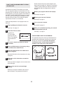
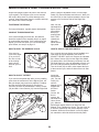
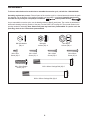
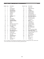
Model No. PFEX4986.0
Serial No.
USER'S MANUAL
Serial Number
Decal
QUESTIONS?
As a manufacturer, we are committed to providing complete
customer satisfaction. If you
have questions, or if parts are
RBEX49840
damaged or missing, PLEASE
CONTACT OUR CUSTOMER
SERVICE DEPARTMENT
DIRECTLY.
CALL TOLL-FREE:
1-888-533-1333
Mon.–Fri., 6 a.m.–6 p.m. MST
ON THE WEB:
www.proformservice.com
CAUTION
Read all precautions and instructions in this manual before using
this equipment. Keep this manual
for future reference.
Visit our website at
www.proform.com
new products, prizes,
fitness tips, and much more!
RBEX49840
TABLE OF CONTENTS
IMPORTANT PRECAUTIONS . . . . . . . . . . . . . . . . . . . . . . . . . . . . . . . . . . . . . . . . . . . . . . . . . . . . . . . . . . . . . . . .2
BEFORE YOU BEGIN . . . . . . . . . . . . . . . . . . . . . . . . . . . . . . . . . . . . . . . . . . . . . . . . . . . . . . . . . . . . . . . . . . . . . .3
ASSEMBLY . . . . . . . . . . . . . . . . . . . . . . . . . . . . . . . . . . . . . . . . . . . . . . . . . . . . . . . . . . . . . . . . . . . . . . . . . . . . . . .4
HOW TO OPERATE THE EXERCISE CYCLE . . . . . . . . . . . . . . . . . . . . . . . . . . . . . . . . . . . . . . . . . . . . . . . . . . . .8
MAINTENANCE AND TROUBLESHOOTING . . . . . . . . . . . . . . . . . . . . . . . . . . . . . . . . . . . . . . . . . . . . . . . . . . .20
CONDITIONING GUIDELINES . . . . . . . . . . . . . . . . . . . . . . . . . . . . . . . . . . . . . . . . . . . . . . . . . . . . . . . . . . . . . . .21
PART LIST . . . . . . . . . . . . . . . . . . . . . . . . . . . . . . . . . . . . . . . . . . . . . . . . . . . . . . . . . . . . . . . . . . . . . . . . . . . . . .22
EXPLODED DRAWING . . . . . . . . . . . . . . . . . . . . . . . . . . . . . . . . . . . . . . . . . . . . . . . . . . . . . . . . . . . . . . . . . . . .23
ORDERING REPLACEMENT PARTS . . . . . . . . . . . . . . . . . . . . . . . . . . . . . . . . . . . . . . . . . . . . . . . . . .Back Cover
LIMITED WARRANTY . . . . . . . . . . . . . . . . . . . . . . . . . . . . . . . . . . . . . . . . . . . . . . . . . . . . . . . . . . . . . .Back Cover
IMPORTANT PRECAUTIONS
WARNING:
To reduce the risk of serious injury, read the following important precautions before using the exercise cycle.
caught on the exercise cycle. Always wear
athletic shoes for foot protection.
1. Read all instructions in this manual and all
warnings on the exercise cycle before using
the exercise cycle.
9. The exercise cycle should not be used by
persons weighing more than 250 pounds.
2. Use the exercise cycle only as described.
10. The pulse sensor is not a medical device.
Various factors, including the user's movement, may affect the accuracy of heart rate
readings. The pulse sensor is intended only
as an exercise aid in determining heart rate
trends in general.
3. It is the responsibility of the owner to ensure
that all users of the exercise cycle are adequately informed of all precautions.
4. The exercise cycle is intended for home use
only. Do not use the exercise cycle in
a commercial, rental, or institutional setting.
11. Always keep your back straight when using
the exercise cycle; do not arch your back.
5. Keep the exercise cycle indoors, away from
moisture and dust. Place the exercise cycle
on a level surface, with a mat beneath it to
protect the floor or carpet. Make sure that
there is enough clearance around the exercise cycle to mount, dismount, and use it.
12. If you feel pain or dizziness while exercising,
stop immediately and cool down.
13. The exercise cycle does not have a freewheel; the pedals will continue to move until
the flywheel stops.
6. Inspect and properly tighten all parts regularly. Replace any worn parts immediately.
14. The decal shown on page 3 has been placed
on the exercise cycle. If the decal is missing,
or illegible, call the toll-free telephone number on the front cover of this manual and
order a free replacement decal. Apply the
decal in the location shown.
7. Keep children under the age of 12 and pets
away from the exercise cycle at all times.
8. Wear appropriate clothes when exercising;
do not wear loose clothes that could become
WARNING:
Before beginning this or any exercise program, consult your physician.
This is especially important for persons over the age of 35 or persons with pre-existing health problems. Read all instructions before using. ICON assumes no responsibility for personal injury or
property damage sustained by or through the use of this product.
2
BEFORE YOU BEGIN
Congratulations for selecting the new PROFORM® GT
90 exercise cycle. Cycling is one of the most effective
exercises for increasing cardiovascular fitness, building
endurance, and toning the entire body. The GT 90
exercise cycle offers an impressive array of features
designed to let you enjoy this healthful exercise in the
comfort and privacy of your home.
model number and serial number before contacting
us. The model number is PFEX4986.0. The serial
number can be found on a decal attached to the exercise cycle (see the front cover of this manual for the
location of the decal).
To avoid a registration fee for any service needed
under warranty, you must register the exercise
cycle at www.proformservice.com/registration.
For your benefit, read this manual carefully before
you use the exercise cycle. If you have questions
after reading this manual, please see the front cover
of this manual. To help us assist you, note the product
Before reading further, please familiarize yourself with
the parts that are labeled in the drawing below.
REV - B
FRONT
21
R E V I
DRAWINGS PREVIOUS TO LA
Bookrack
REV
ECN
DESCRIPTI
A 1274-10 ADD PART NO.
Fan
B 2054-05
Console
CORRECT THE O
Handgrip Pulse Sensor
Handlebar
Decal shown at 100%
Seat
Seat Post
Water Bottle Holder*
PART NO. BACKGROUND
209490
210124
Seat Knob
CLEAR
CLEAR
TEXT/BORDER
WHITE OPAQUE
BLACK OPAQUE
PRODUCT COLOR
DARK
LIGHT
Wheel
Side Shield
Pedal with Strap
BACK
¥ Print
RIGHT SIDE
on Clear 4 mil. vinyl backed with super aggressive adhesive.
¥ Screen Print Black opaque:
RELEASE
APPROVALS
Warning , and triangle with
! reversed
DRAWN BY:
M.BENNETT
CHECKED BY: D.SHAW
¥ Print PMS 151 Orange: The box behind the signal word.
Leveling
DSGN is
MNG.
¥ Die Pad
cut decal to dimensions: 1.35" x 2.55" corner radius
.125 R.EVANS
(x4).
ENG. APP.
B.ELLIS
¥ Place decal as shown.
out to 151 Orange.
DATE
3
TOLERANCES
X. +
01/02/04 X BIKES
GYMS
.X +
01/02/04
.XX +
*No waterSTEPPERS
bottle
is
included
01/02/04
TREADMILLS
.XXX +
01/02/04
MISC.
ANGLES +
Health &
Fitness,
REVISED 02/06/04
PRODUCTS
TITLE:DECAL,
PROJECT/MODE
NO. PER UNIT
DWG.NO. 20
REV. LEVEL:B
This drawing and all information thereof is the p
CONFIDENTIAL. This drawing is NOT to be made pub
subject to return upon demand, and is NOT to be u
to the interests of ICON Health and Fitness, Inc.
Inc.
CONDITIONING GUIDELINES
Fat Burning
WARNING:
To burn fat effectively, you must exercise at a relatively low intensity level for a sustained period of time.
During the first few minutes of exercise, your body
uses easily accessible carbohydrate calories for energy. Only after the first few minutes of exercise does
your body begin to use stored fat calories for energy. If
your goal is to burn fat, adjust the intensity of your
exercise until your heart rate is near the lowest number or the middle number in your training zone as you
exercise.
Before beginning this or any exercise program, consult your physician. This is especially important for individuals over the age
of 35 or individuals with pre-existing health
problems.
The pulse sensor is not a medical device.
Various factors may affect the accuracy of
heart rate readings. The pulse sensor is
intended only as an exercise aid in determining heart rate trends in general.
Aerobic Exercise
If your goal is to strengthen your cardiovascular system, your exercise must be “aerobic.” Aerobic exercise
is activity that requires large amounts of oxygen for
prolonged periods of time. This increases the demand
on the heart to pump blood to the muscles, and on the
lungs to oxygenate the blood. For aerobic exercise,
adjust the intensity of your exercise until your heart
rate is near the highest number in your training zone.
The following guidelines will help you to plan your
exercise program. Remember that proper nutrition and
adequate rest are essential for successful results.
EXERCISE INTENSITY
Whether your goal is to burn fat or to strengthen your
cardiovascular system, the key to achieving the
desired results is to exercise with the proper intensity.
The proper intensity level can be found by using your
heart rate as a guide. The chart below shows recommended heart rates for fat burning, maximum fat burning, and cardiovascular (aerobic) exercise.
WORKOUT GUIDELINES
Each workout should include the following three parts:
A warm-up, consisting of 5 to 10 minutes of stretching
and light exercise. A proper warm-up increases your
body temperature, heart rate, and circulation in preparation for exercise.
Training zone exercise, consisting of 20 to 30 minutes of exercising with your heart rate in your training
zone. (During the first few weeks of your exercise program, do not keep your heart rate in your training
zone for longer than 20 minutes.)
A cool-down, with 5 to 10 minutes of stretching. This
will increase the flexibility of your muscles and will
help to prevent post-exercise problems.
To find the proper heart rate for you, first find your age
at the bottom of the chart (ages are rounded off to the
nearest ten years). Next, find the three numbers above
your age; the three numbers are your “training zone.”
The lowest number is the recommended heart rate for
fat burning; the middle number is the recommended
heart rate for maximum fat burning; and the highest
number is the heart rate for aerobic exercise.
EXERCISE FREQUENCY
To maintain or improve your condition, plan three workouts each week, with at least one day of rest between
workouts. After a few months of regular exercise, you
may complete up to five workouts each week, if
desired. The key to success is make exercise a regular and enjoyable part of your everyday life.
21
1. Identify the Front Stabilizer (2), which has Wheels
(17) attached to it. Attach the Front Stabilizer to the
Frame (1) with two M10 x 92mm Carriage Bolts (62)
and two M10 Nylon Locknuts (48).
1
17
62
1
48
2
2. Attach the Rear Stabilizer (3) to the Frame (1) with
two M10 x 105mm Carriage Bolts (64) and two M10
Nylon Locknuts (48).
2
48
3
48
1
64
3. While another person holds the Handlebar Post (6)
near the Frame (1), connect the Upper Wire
Harness (16) to the Lower Wire Harness (24). Next,
pull the excess Upper Wire Harness out of the top of
the Handlebar Post, and insert the Handlebar Post
into the Frame. Be careful not to pinch the Wire
Harnesses.
3
6
Slide the Round Collar (13) down the Handlebar
Post (6) and press it into the Frame (1). Attach the
Round Collar with an M6 x 8mm Screw (26).
13
Note: There are two sets of holes in the
Handlebar Post (6) so that it can be attached at
either of two heights. Attach the Handlebar Post to
the Frame (1) at the desired height with four M8 x
25mm Button Screws (19) and four M8 Split
Washers (28).
16
26
19
24
28
28
1
5
19
4. While another person holds the Handlebar (7) near
the Handlebar Post (6), feed the Upper Wire
Harness (16) and the Pulse Sensor Wire (45) up
through the indicated hole in the Handlebar. Attach
the Handlebar to the Handlebar Post with three
M8 x 25mm Button Screws (19) and three M8 Split
Washers (28).
4
Hole
45
7
6
28
16
19
28
19
5. The Console (9) requires four “D” batteries (not
included); alkaline batteries are recommended.
Press the tab on the battery cover and remove the
battery cover. Press four batteries into the battery
clips; make sure that the batteries are oriented
as shown by the diagram inside the battery
clips. Then, reattach the battery cover.
5
9
Battery
Cover
Batteries
6. Insert the Bookrack (8) into the slots in the Console
(9). Attach the Bookrack with two M4 x 25mm
Screws (20). Be careful not to pinch the wires in
the Console.
6
8
9
20
7. While another person holds the Console (9) near
the Handlebar (7), connect the Pulse Sensor Wire
(45) and the Upper Wire Harness (16) to the corresponding wires on the Console.
7
9
Insert all excess wiring downward into the
Handlebar Post (6). Attach the Console (9) to the
Handlebar (7) with four M4 x 16mm Screws (21).
Be careful not to pinch the Pulse Sensor Wires
(45) or the Upper Wire Harness (16).
7
21
Console
Wires
45
16
21
6
6
8. Attach the Seat (12) to the Seat Post (11) with four
M8 Nylon Locknuts (56) and four M8 Split Washers
(28). Note: The Nylon Locknuts and Split
Washers may be pre-attached to the Seat.
8
12
Turn the Seat Knob (31) counterclockwise two or
three turns to loosen it. Next, pull the Knob, insert
the Seat Post (11) into the Frame (1), and then
release the Knob. Slide the Round Collar (13) down
the Seat Post and press it into the Frame. Attach
the Round Collar to the Frame with an M6 x 8mm
Screw (26). Move the Seat Post up and down
slightly until the pin on the Knob snaps into one
of the holes in the Seat Post. Then, turn the Knob
clockwise until it is tight.
11
28
13
1
56
26
31
9. Identify the Left Pedal (40); the threaded shaft on
each Pedal is marked with an “L” for left or an “R”
for right. Firmly tighten the Left Pedal counterclockwise into the Crank Assembly (33). Tighten the
Right Pedal (not shown) clockwise into the Crank
Assembly. Important: Tighten both Pedals as
firmly as possible. After using the exercise cycle
for one week, retighten the Pedals. For best performance, keep the Pedals tightened.
9
33
41
40
Identify the Left Pedal Strap (41), which is marked
with an “L.” Attach the Left Pedal Strap to the Left
Pedal (40), and adjust the Left Pedal Strap to the
desired position. Attach and adjust the Right Pedal
Strap (not shown) in the same way.
10. Attach the Water Bottle Holder (63) to the Frame (1)
with two M4 x 19mm Screws (59). Note: The water
bottle holder is designed to be used with your own
water bottle.
10
59
63
1
11. Make sure that all parts are properly tightened before you use the exercise cycle. Note: Some hardware may be left over after assembly is completed. Place a mat under the exercise cycle to protect the
floor or carpet.
7
HOW TO INSTALL THE RECEIVER FOR THE OPTIONAL CHEST PULSE SENSOR
If you purchase the optional chest pulse sensor (see page 19), follow the steps below to install the receiver
included with the chest pulse sensor.
1. See assembly step 6 on page 6, and remove the two
M4 x 25mm Screws (not shown) and the Bookrack (8).
1
8
9
Next, look under the Console (9) and locate the three
indicated screws (not shown). Remove the three
screws. Do not remove the screws attaching the
Console to the Handlebar (7).
7
Screws
2. Carefully lift the top of the Console (9) as shown. Using
the two small screws included with the chest pulse sensor, attach the receiver to the indicated plastic posts on
the Console. Make sure that the receiver is turned
exactly as shown. Connect the wire on the receiver to
the indicated wire on the Console.
2
9
Screws
See step 1 above. Lower the top of the Console (9).
Make sure that no wires are pinched. Reattach the
top of the Console with the three screws removed in
step 1. See assembly step 6 on page 6, and reattach
the Bookrack (8) with the two M4 x 25mm Screws (not
shown). Note: The remaining wires included with the
chest pulse sensor may be discarded.
Wire
Receiver
Posts
HOW TO OPERATE THE EXERCISE CYCLE
HOW TO ADJUST THE HEIGHT OF THE SEAT
HOW TO ADJUST THE HANDLEBARS
For effective exercise, the seat should be at the proper
height. As you pedal, there should be a slight bend in
your knees when the pedals are in the lowest position.
To adjust the seat, first turn the seat knob counterclockwise several
turns to loosen it.
Next, pull the knob,
Seat
slide the seat post
up or down as
desired, and then
release the knob.
Move the seat
Seat Post
post up or down
slightly to make
sure that it locks
Seat
Knob
into place. Turn
the knob clockwise
to retighten it.
The handlebars can be adjusted to either of two
heights. To adjust the handlebars, see assembly step
3 on page 5.
HOW TO ADJUST THE PEDAL STRAPS
To adjust the pedal
straps, first pull the
ends of the straps
off the tabs on the
pedals. Press the
straps back onto
the tabs using different holes in the
straps.
Strap
RBEX49840
8
Tab
DIAGRAM OF THE CONSOLE
Note: If there is a sheet of clear plastic on
the face of the console, remove the plastic.
FEATURES OF THE CONSOLE
The advanced console offers a selection of features
designed to make your workouts more enjoyable and
effective. When you use the manual mode of the console, you can change the resistance of the pedals with
the touch of a button. As you exercise, the console will
provide continuous exercise feedback. You can even
measure your heart rate using the handgrip pulse sensor. Note: See page 19 for information about the
optional chest pulse sensor.
The console also offers six preset programs. Each program automatically changes the resistance of the pedals and prompts you to increase or decrease your pace
as it guides you through an effective workout.
In addition, the console features two heart rate programs that automatically change the resistance of the
pedals and prompt you to vary your pace to keep your
heart rate near a target heart rate as you exercise.
The console also features iFIT.com interactive technology. Having iFIT.com interactive technology is like hav-
9
ing a personal trainer in your home. Using the included
audio cable, you can connect the exercise cycle to your
home stereo, portable stereo, computer, or VCR and
play special iFIT.com CD and video programs (iFIT.com
CDs and videocassettes are available separately).
iFIT.com CD and video programs automatically control
the resistance of the pedals and prompt you to vary
your pace as a personal trainer coaches you through
every step of your workout. High-energy music provides added motivation. To purchase iFIT.com CDs
and videocassettes, call the toll-free telephone
number on the front cover of this manual.
With the exercise cycle connected to your computer,
you can also go to our Web site at www.iFIT.com and
access programs directly from the Internet. Explore
www.iFIT.com for more information.
To use the manual mode of the console, see page
10. To use a preset program, see page 12. To use a
heart rate program, see page 13. To use an
iFIT.com CD or videocassette, see page 18. To use
a program directly from our Web site, see page 19.
your pedaling pace, in revolutions per minute
(RPM). The display will change from one number
to the next every few seconds, as shown by the
indicators in the display. Note: When a program is
selected, the display will show the time remaining
in the program instead of the elapsed time. Each
time the resistance of the pedals changes, the
display will show the resistance level.
HOW TO USE THE MANUAL MODE
1
Begin pedaling to activate the console.
To activate the console, begin pedaling. After a
few seconds, the console displays will light. A
tone will then sound and the console will be
ready for use.
2
If desired, you can
select a single
mode for continuous display. Press
the left Mode button
repeatedly until the
desired mode indicator is lit; make sure that the Scan indicator is
not lit.
Select the manual mode.
When the power is
turned on, the
manual mode will
be selected. If you
have selected a
program or the
iFIT.com mode,
select the manual mode by pressing the Program
Select button repeatedly until a track appears in
the matrix.
3
The lower
display—The lower
display will show
the approximate
number of calories
you have burned
and your pedaling
speed. The display will change from one number
to the next every few seconds, as shown by the
indicators in the display. The display will also
show your heart rate (pulse) when you use the
handgrip pulse sensor or the optional chest pulse
sensor.
Begin pedaling and change the resistance of
the pedals as desired.
As you pedal,
change the resistance of the pedals by pressing the
Resistance buttons. There are
ten resistance levels. Note: After the buttons are pressed, it will
take a moment for the pedals to reach the selected resistance level.
4
Note: The console
can show speed
and distance in
either miles or
kilometers. The letters MPH or KPH
will appear in the
lower display to show which unit of measurement
is selected. To change the unit of measurement,
first hold down the Program Select button for a few
seconds. An E (for English) or an M (for metric) will
appear in the lower display. Press the Resistance
+ button to change the unit of measurement. Then,
press the Cooling Fan button. Note: When the batteries are replaced, it may be necessary to reselect the desired unit of measurement.
Monitor your progress with the matrix and the
two displays.
The matrix—
When the manual
mode or the
iFIT.com mode is
selected, the
matrix will show a
track representing
1/4 mile. As you exercise, the indicators around
the track will light, one at a time, until the entire
track is lit. The track will then darken and a new
lap will begin.
If desired, you can select a single mode for continuous display. Press the right Mode button
repeatedly until the desired mode indicator is lit;
make sure that the Scan indicator is not lit.
The upper display—The upper
display will show
the elapsed time,
the distance you
have pedaled, and
10
5
Note: If you continue to hold the pulse sensor, the
lower display will show your heart rate for up to
30 seconds. The display will then show your heart
rate along with the other modes.
Measure your heart rate if desired.
You can measure your heart rate using either the
handgrip pulse sensor or the optional chest pulse
sensor. Note: If you hold the handgrip pulse
sensor and wear the chest pulse sensor at the
same time, the console will not display your
heart rate accurately.
If your heart rate is not shown, make sure that
your hands are positioned as described. Avoid
moving your hands excessively or squeezing the
metal contacts too tightly. For optimal performance,
periodically clean the metal contacts using a soft
cloth; never use alcohol, abrasives, or chemicals
to clean the contacts.
If there are
sheets of
clear plastic
on the metal
contacts on
the handgrip
Contacts
pulse sensor,
remove the
plastic. To
measure your heart rate, hold the contacts; your
palms must be resting on the contacts closest to
you, and your fingers must be touching the opposite contacts. Avoid moving your hands.
6
Turn on the fan if desired.
To turn on the fan at low speed, press the Cooling
Fan button. To turn on the fan at high speed,
press the button a second time. To turn off the
fan, press the button a third time. Note: If the fan
is turned on but the pedals are not moved for thirty seconds, the fan will automatically turn off.
7
When your pulse
is detected, the
heart-shaped indicator in the lower
display will flash
each time your
heart beats, and
your heart rate will be shown. For the most accurate heart rate reading, hold the contacts for at
least 15 seconds.
When you are finished exercising, the console
will automatically turn off.
If the pedals are not moved for a few seconds, a
tone will sound, the console will pause, and the
upper display will begin to flash.
If the pedals are not moved for about five minutes, the console will turn off and the displays will
be reset.
RBEX49840
11
The program will continue until the resistance setting for the last segment is shown in the Current
Segment column of the matrix and no time
remains in the program.
HOW TO USE PRESET PROGRAMS
1
Begin pedaling to activate the console.
Note: During the program, you can override the
resistance setting for the current segment by
pressing the Resistance buttons. However, when
the next segment begins, the resistance will automatically change if a different resistance setting is
programmed for the next segment. If you stop
pedaling for several seconds, a tone will sound
and the program will pause. To restart the program, simply resume pedaling.
See step 1 on page 10.
2
Select one of the six preset programs.
When the power is
turned on, the
manual mode will
be selected. To
select a preset
program, press the
Program Select
button repeatedly until “P1,” “P2,” “P3,” “P4,”
“P5,” or “P6” appears in the lower display.
4
During preset programs, the pace
guide will prompt
you to increase or
decrease your pedaling pace. When
one of the indicators on the left side
of the pace guide
lights, increase
your pace; when
one of the indicators on the right side lights, decrease your pace.
When the center indicator lights, maintain your
current pace. Important: The pace settings of
the program are intended only to provide a
goal. Make sure to pedal at a pace that is
comfortable for you.
When a preset program is selected, the matrix
will show the first six resistance settings of the
program.
3
Use the pace (RPM) guide.
Press the Program Start button or begin
pedaling to start the program.
Each program is divided into several time segments of different lengths. One resistance setting
is programmed for each segment. (The same
resistance setting may be programmed for two or
more consecutive segments.)
The resistance
Current Segment
setting for the first
segment will be
shown in the flashing Current
Segment column
of the matrix. The
resistance settings
for the next five
segments will be shown in the columns to the
right.
5
Monitor your progress with the two displays.
See step 4 on page 10.
6
Measure your heart rate if desired.
See step 5 on page 11.
When only three seconds remain in the first segment of the program, a series of tones will sound;
all resistance settings will then move one column
to the left. The resistance setting for the second
segment will then be shown in the flashing
Current Segment column and the resistance of
the pedals will automatically change to the resistance setting for the second segment.
7
Turn on the fan if desired.
See step 6 on page 11.
8
When you are finished exercising, the console
will automatically turn off.
See step 7 on page 11.
12
3
HOW TO USE HEART RATE PROGRAMS
When heart rate
program 1 is
selected, you must
enter your age. If
you have already
entered your age,
press the Enter
(Program Start)
button and go to
step 5. If you have
not entered your
age, press the + or
– button repeatedly to enter your age, and then
press the Enter button. Note: Once you have
entered your age, it will be saved in memory.
Heart rate program 1 is designed to keep your heart
rate between 60 percent and 85 percent of your estimated maximum heart rate while you exercise. Note:
Your maximum heart rate is estimated by subtracting
your age from 220. For example, if you are 30 years
old, your estimated maximum heart rate is 190 (220 –
30 = 190).
Heart rate program 2 will keep your heart rate near a
target heart rate that you select.
Follow the steps below to use a heart rate program.
1
Begin pedaling to activate the console.
See step 1 on page 10.
2
Enter your age.
4
Enter a target heart rate.
When heart rate
program 2 is
selected, you must
enter a target heart
rate. (See the heart
rate chart on page
21 for heart rate
guidelines.) To
enter a target heart
rate, press the + or
– button repeatedly, and then press
the Enter (Program Start) button.
Select one of the heart rate programs.
To select a heart
rate program,
press the Program
Select button
repeatedly until
“H1” or “H2”
appears in the
lower display.
If you selected
heart rate program
1, the matrix will
show the first six
target heart rate
settings of the program.
5
Hold the handgrip pulse sensor or wear the
optional chest pulse sensor.
To use a heart rate program, you must hold the
handgrip pulse sensor or wear the optional chest
pulse sensor. If you use the handgrip pulse sensor, it is not necessary to hold the handgrips continuously during the program. However, you
should hold the handgrips frequently for the program to operate properly. Each time you hold
the handgrips, keep your hands on the metal
contacts for at least 30 seconds. Note: When
you are not holding the handgrips, the letters
“PLS” will appear in the lower display instead of
your heart rate.
If you selected
heart rate program
2, a heart symbol
will appear in the
matrix.
If you selected heart rate program 1, go to
step 3. If you selected heart rate program 2,
go to step 4.
13
6
Begin pedaling.
The pace guide
will help you to
maintain a constant pace during
the program. When
one of the indicators on the left side
of the pace guide
lights, increase
your pace; when
one of the indicators on the right
side lights, decrease your pace. When the center
indicator lights, maintain your current pace.
Important: The pace settings of the program
are intended only to provide a goal. Make
sure to pedal at a pace that is comfortable for
you.
Each heart rate program is divided into 30 oneminute segments. One target heart rate is programmed for each segment. Note: The same target heart rate may be programmed for two or
more consecutive segments. If heart rate program 2 is selected, the same target heart rate is
programmed for all segments.
If heart rate proCurrent Segment
gram 1 is selected, the target
heart rate setting
for the first segment will be
shown in the
flashing Current
Segment column
of the matrix. The target heart rate settings for the
next five segments will be shown in the columns
to the right. When only three seconds remain in
the first segment of the program, a series of
tones will sound; all target heart rate settings will
then move one column to the left. The target
heart rate setting for the second segment will
then be shown in the flashing Current Segment
column.
The program will continue until the target heart
rate setting for the last segment is shown in the
Current Segment column of the matrix and no
time remains in the program.
Note: During the program, you can manually
change the resistance setting, if desired, by
pressing the Resistance buttons. However, when
the console compares your heart rate to the target heart rate, the resistance may automatically
change. If you stop pedaling for several seconds,
a tone will sound and the program will pause. To
restart the program, simply resume pedaling.
If heart rate program 2 is selected, the same
target heart rate is programmed for all segments;
therefore, the target heart rate settings will not be
shown in the matrix. When only three seconds
remain in the first segment of the program, a
series of tones will sound and the time will flash
in the right display.
7
Monitor your progress with the two displays.
See step 4 on page 10.
As you pedal, the console will regularly compare
your heart rate to the target heart rate. If your
heart rate is too far below or above the target
heart rate, the resistance of the pedals will automatically increase or decrease to being your heart
rate closer to the target heart rate.
8
Turn on the fan if desired.
See step 6 on page 11.
9
When you are finished exercising, the console will automatically turn off.
See step 7 on page 11.
14
HOW TO CONNECT YOUR PORTABLE STEREO
HOW TO CONNECT YOUR CD PLAYER, VCR,
OR COMPUTER
Note: If your stereo has an RCA-type AUDIO OUT
jack, see instruction A below. If your stereo has a
1/8" LINE OUT jack, see instruction B. If your
stereo has only a PHONES jack, see instruction C.
To use iFIT.com CDs, the exercise cycle must be connected to your portable CD player, portable stereo,
home stereo, or computer with CD player. See pages
15 and 16 for connecting instructions. To use iFIT.com
videocassettes, the exercise cycle must be connected
to your VCR. See page 17 for connecting instructions.
To use iFIT.com programs directly from our Web
site, the exercise cycle must be connected to your
home computer. See page 16 for connecting instructions.
OUT
A. Plug one end of the audio cable into theAUDIO
jack
RIGHT
beneath the console. Plug the other end of the cable
into the adapter. Plug the adapter into anLEFTAUDIO
OUT jack on your stereo.
A, B
AUDIO OUT
HOW TO CONNECT YOUR PORTABLE CD PLAYER
RIGHT
LEFT
A
Note: If your CD player has separate LINE OUT and
PHONES jacks, see instruction A below. If your CD
player has only one jack, see instruction B.
A. Plug one end of the audio cable into the jack
beneath the console. Plug the other end of the
cable into the LINE OUT jack on your CD player.
Plug your headphones into the PHONES jack.
A
PHONES LINE OUT
LINE OUT
PHONES LINE OUT
LINE OUT
PHONES
PHONES
Adapter
Audio Cable
LINE OUT
B. Plug one end of the audio cable into the jack
beneath the console. Plug the other end of the
cable into the LINE OUT jack on your stereo. Do
not use the adapter.
A
C. Plug one end of the audio cable into the jack
beneath the console. Plug the other end of the
cable into a 1/8" Y-adapter (available at electronics
stores). Plug the Y-adapter into the PHONES jack
on your stereo. Plug your headphones into the
other side of the Y-adapter.
LINE OUT
Headphones
Audio
Cable
B
C
A
A
B. Plug one end of the audio cable into the jack
beneath the console. Plug the other end of the
cable into a 1/8" Y-adapter (available at electronics
stores). Plug the Y-adapter into the PHONES jack
on your CD player. Plug your headphones into the
other side of the Y-adapter.
B
Audio
Cable
PHONES
1/8"
Y-adapter
B
Headphones
PHONES
PHONES
PHONES
PHONES
C
PHONES
Audio
Cable
1/8"
Y-adapter
Headphones
C
B
B
15
HOW TO CONNECT YOUR HOME STEREO
HOW TO CONNECT YOUR COMPUTER
Note: If your stereo has an unused LINE OUT jack,
see instruction A below. If the LINE OUT jack is
being used, see instruction B.
Note: If your computer has a 1/8" LINE OUT jack,
see instruction A. If your computer has only a
PHONES jack, see instruction B.
A. Plug one end of the audio cable into the jack
beneath the console. Plug the other end of the
cable into the adapter. Plug the adapter into the
LINE OUT jack on your stereo.
A. Plug one end of the audio cable into the jack
beneath the console. Plug the other end of the
cable into the LINE OUT jack on your computer.
A
A
CD
LINE OUT
VCR
Amp
CD
LINE OUT
Audio
Cable
LINE OUT
VCR
LINE OUT
Amp
Adapter
LINE OUT
LINE OUT
Audio Cable
A
B. Plug one end of the audio cable into the jack
beneath the console. Plug the other end of the
cable into a 1/8" Y-adapter (available at electronics
stores). Plug the Y-adapter into the PHONES jack
on your computer. Plug your headphones or speakers into the other side of the Y-adapter.
A
B. Plug one end of the audio cable into the jack
beneath the console. Plug the other end of the
cable into the adapter. Plug the adapter into an
RCA Y-adapter (available at electronics stores).
Next, remove the wire that is currently plugged into
the LINE OUT jack on your stereo and plug the
wire into the unused side of the Y-adapter. Plug the
Y-adapter into the LINE OUT jack on your stereo.
A
A
B
PHONES
PHONES
CD
VCR
B
Amp
CD
LINE OUT
Audio Cable
VCR
Amp
1/8"
Y-adapter
LINE OUT
B
Headphones/Speakers
RCA
Y-adapter
Audio
Cable
B
Adapter
Wire removed from
LINE OUT jack
B
B
16
HOW TO CONNECT YOUR VCR
B. Plug one end of the audio cable into the jack
beneath the console. Plug the other end of the
cable into the adapter. Plug the adapter into an
RCA Y-adapter (available at electronics stores).
Next, remove the wire that is currently plugged into
the AUDIO OUT jack on your VCR and plug the
wire into the unused side of the Y-adapter. Plug the
Y-adapter into the AUDIO OUT jack on your VCR.
Note: If your VCR has an unused AUDIO OUT jack,
see instruction A below. If the AUDIO OUT jack is
being used, see instruction B. If you have a TV
with a built-in VCR, see instruction B. If your VCR
is connected to your home stereo, see HOW TO
CONNECT YOUR HOME STEREO on page 16.
A
A. Plug one end of the audio cable into the jack
beneath the console. Plug the other end of the
cable into the adapter. Plug the adapter into the
AUDIO OUT jack on your VCR.
B
ANT. IN
VIDEO AUDIO
IN
RF OUT
CH
3 4
OUT
A
RCA Y-adapter
ANT. IN
VIDEO AUDIO
IN
RF OUT
CH
3 4
OUT
Audio Cable Adapter
AUDIO OUT
RIGHT
LEFT
Wire removed from
AUDIO OUT jack
Adapter
Audio Cable
B
A
ANT. IN
AUDIO OUT
VIDEO AUDIO
IN
RF OUT
CH
3 4
OUT
RIGHT
LEFT
C
B
AUDIO OUT
RIGHT
LEFT
17
The program will function in almost the same way
as a preset program (see steps 3 and 4 on page
12). However, an electronic “chirping” sound will
alert you when the resistance of the pedals and/or
the target pace is about to change.
HOW TO USE IFIT.COM CD AND VIDEO
PROGRAMS
To use iFIT.com CDs or videocassettes, the exercise
cycle must be connected to your portable CD player,
portable stereo, home stereo, computer with CD player, or VCR. See HOW TO CONNECT YOUR CD
PLAYER, VCR, OR COMPUTER on pages 15 to 17.
To purchase iFIT.com CDs and videocassettes, call
the toll-free telephone number on the front cover
of this manual.
Note: If the resistance of the pedals and/or the
target pace does not change when a “chirp” is
heard:
• Make sure that the indicator above the
iFIT.com button is lit.
• Adjust the volume of your CD player or VCR.
If the volume is too high or too low, the console may not detect the program signals.
Follow the steps below to use an iFIT.com CD or
video program.
1
• Make sure that the audio cable is properly
connected and that it is fully plugged in.
Begin pedaling to activate the console.
See step 1 on page 10.
2
5
Select the iFIT.com mode.
See step 4 on page 10.
To select the
iFIT.com mode,
press the iFIT.com
button. The indicator
on the button will
light.
3
6
Measure your heart rate if desired.
See step 5 on page 11.
7
Turn on the fan if desired.
See step 6 on page 11.
Insert the iFIT.com CD or videocassette.
8
If you are using an iFIT.com CD, insert the CD
into your CD player. If you are using an iFIT.com
videocassette, insert the videocassette into your
VCR.
4
Monitor your progress with the two displays.
When you are finished exercising, the console
will automatically turn off.
See step 7 on page 11.
Press the play button on your CD player or
VCR.
A moment after the play button is pressed, your
personal trainer will begin guiding you through
your workout. Simply follow your personal trainer’s
instructions.
18
almost the same way as a preset program (see
steps 3 and 4 on page 12). However, an electronic
“chirping” sound will alert you when the resistance
of the pedals and/or the target pace is about to
change.
HOW TO USE PROGRAMS DIRECTLY FROM
OUR WEB SITE
Our Web site at www.iFIT.com allows you to play
iFIT.com programs directly from the Internet. To use
programs from our Web site, the exercise cycle must
be connected to your home computer. See HOW TO
CONNECT YOUR COMPUTER on page 16. In addition, you must have an Internet connection and an
Internet service provider. A list of specific system
requirements is found on our Web site.
8
See step 4 on page 10.
9
10 Turn on the fan if desired.
See step 6 on page 11.
Begin pedaling to activate the console.
you are finished exercising, the console
11 When
will automatically turn off.
See step 1 on page 10.
2
Select the iFIT.com mode.
See step 7 on page 11.
To select the
iFIT.com mode,
press the iFIT.com
button. The indicator
on the button will
light.
3
Go to your computer and start an Internet
connection.
4
Start your Web browser, if necessary, and go
to our Web site at www.iFIT.com.
5
Follow the desired links on our Web site to
select a program.
THE OPTIONAL CHEST PULSE SENSOR
The optional chest pulse sensor provides hands-free
operation and continuously monitors your heart rate
during your workouts. To purchase the optional
chest pulse sensor, call the toll-free telephone
number on the front cover of this manual.
Read and follow the on-line instructions for using
a program.
6
Follow the on-line instructions to start the
program.
When you start the program, an on-screen countdown will begin.
7
Measure your heart rate if desired.
See step 5 on page 11.
Follow the steps below to use a program from our
Web site.
1
Monitor your progress with the two displays.
Return to the exercise cycle and begin
pedaling.
When the on-screen countdown ends, the program will begin. The program will function in
19
MAINTENANCE AND TROUBLESHOOTING
Inspect and properly tighten all parts of the exercise
cycle regularly. The exercise cycle can be cleaned
with a soft, damp cloth. To prevent damage to the
console, keep liquids away from the console and keep
the console out of direct sunlight.
Shield. Using an adjustable wrench, turn the Right
Pedal (37) counterclockwise and remove it. Next, turn
the Crank (33) so that it points toward the front of the
exercise cycle, and then slide off the Right Side
Shield.
TIGHTENING THE PEDALS
If the console display becomes dim, the batteries
should be replaced. See assembly step 5 on page 6
for replacement instructions. If the console does not
display your heart rate when you use the handgrip
pulse sensor, see step 5 on page 13.
Next, turn the
indicated M8 x
40mm Screw
(58) until the
Belt (69) is
properly tightened. Then,
reattach the
right side
shield and the
right pedal.
HOW TO LEVEL THE EXERCISE CYCLE
HOW TO ADJUST THE REED SWITCH
If the exercise
cycle rocks slightly on your floor,
turn one or both
of the leveling
pads until the
exercise cycle is
level.
If the console does not display correct feedback, the
reed switch should be adjusted. See HOW TO
ADJUST THE BELT at the left. Remove the indicated
M4 x 38mm Screws (30) from the Right Side Shield
(5) and the M4 x 16mm Screws (not shown) from the
Left Side Shield (4). Using an adjustable wrench, turn
the Left Pedal (not shown) clockwise and remove it.
Turn the Crank (33) so that it points toward the front
of the exercise cycle, and then slide off the Left Side
Shield.
For best performance, regularly tighten both pedals.
CONSOLE TROUBLESHOOTING
Leveling
Pads
HOW TO ADJUST THE BELT
37
4
33
30
69
Locate the
Reed Switch
33
(44). Turn the
Crank (33)
until the
Magnet (18) is
aligned with
the Reed
21 18
Switch.
44
Loosen, but
do not
remove, the
indicated M4 x
16mm Screw
(21). Slide the
Reed Switch slightly closer to or away from the
Magnet. Then, retighten the Screw. Turn the Crank for
a moment. Repeat until the console displays correct
feedback. When the Reed Switch is correctly adjusted, reattach the left side shield and the left pedal.
If you can feel the pedals slip while you are pedaling,
even when the resistance is at the highest level, the
Belt (not shown) may need to be adjusted. To adjust
the Belt, the Right Side Shield (5) must first be
removed. Remove the indicated M4 x 38mm Screws
(30) and M4 x 16mm Screws (21) from the Right Side
5
58
21
20
ASSEMBLY
To hire an authorized service technician to assemble the exercise cycle, call toll-free 1-800-445-2480.
Assembly requires two persons. Place all parts of the exercise cycle in a cleared area and remove the packing materials. Do not dispose of the packing materials until assembly is completed. Assembly requires the
included hex keys and your own phillips screwdriver
and adjustable wrench
.
As you assemble the exercise cycle, use the drawings below to identify small parts. The number in parentheses
below each drawing is the key number of the part, from the PART LIST on page 22. The second number is the
quantity needed for assembly. Note: Some small parts may have been preassembled. If a part is not in the
parts bag, check to see if it has been preassembled.
M8 Split Washer
(28)–11
M6 x 8mm
Screw (26)–2
M8 x 25mm Button
Screw (19)–7
M10 Nylon
Locknut (48)–4
M8 Nylon
Locknut (56)–4
M4 x 19mm
Screw (59)–2
M4 x 16mm
Screw (21)–4
M10 x 92mm Carriage Bolt (62)–2
M10 x 105mm Carriage Bolt (64)–2
4
M4 x 25mm
Screw (20)–2
PART LIST—Model No. PFEX4986.0
Key No. Qty.
1
2
3
4
5
6
7
8
9
10
11
12
13
14
15
16
17
18
19
20
21
22
23
24
25
26
27
28
29
30
31
32
33
34
35
36
1
1
1
1
1
1
1
1
1
2
1
1
2
2
2
1
2
1
7
2
16
1
1
1
2
2
2
11
2
5
1
1
1
1
2
2
Description
R0706A
Key No. Qty.
Frame
Front Stabilizer
Rear Stabilizer
Left Side Shield
Right Side Shield
Handlebar Post
Handlebar
Bookrack
Console
Handlebar Foam
Seat Post
Seat
Round Collar
Round Bushing
Handlebar Endcap
Upper Wire Harness
Wheel
Magnet
M8 x 25mm Button Screw
M4 x 25mm Screw
M4 x 16mm Screw
“C” Magnet
1" x 2" Endcap
Lower Wire Harness
M4 x 12mm Screw
M6 x 8mm Screw
Rear Stabilizer Endcap
M8 Split Washer
Leveling Pad
M4 x 38mm Screw
Seat Knob
Crank Bearing Set
Crank Assembly
Pulley
Pillow Block Set
Snap Ring
37
38
39
40
41
42
43
44
45
46
47
48
49
50
51
52
53
54
55
56
57
58
59
60
61
62
63
64
65
66
67
68
69
#
#
#
1
1
1
1
1
2
1
1
1
1
2
6
1
1
1
1
1
1
1
5
4
1
2
2
4
2
1
2
1
1
4
1
1
1
1
2
Description
Right Pedal
Right Pedal Strap
Flywheel
Left Pedal
Left Pedal Strap
Stabilizer Endcap
Flywheel Spacer
Reed Switch/Wire
Pulse Sensor Assembly
Reed Switch Clamp
M10 x 60mm Button Bolt
M10 Nylon Locknut
Idler Arm Assembly
Long Spacer
Spring
M6 x 50mm Bolt
Small Pulley
Flywheel Washer
Resistance Motor
M8 Nylon Locknut
M5 Washer
M8 x 40mm Screw
M4 x 19mm Screw
M6 Nut
M6 x 13mm Button Screw
M10 x 92mm Carriage Bolt
Water Bottle Holder
M10 x 105mm Carriage Bolt
Resistance Cable
Wiring Anchor
M6 x 18mm Bolt
Nylon Zip Tie
Belt
User’s Manual
Hex Key
Assembly Tool
Note: “#” indicates a non-illustrated part. Specifications are subject to change without notice. See the back
cover of this manual for information about ordering replacement parts.
22
EXPLODED DRAWING—Model No. PFEX4986.0
R0706A
8
15
10
28
21
23
19
28
19
21
21
6
12
9
7
10
20
16
45
31
34
11
28
18
13
69
67
14
25
26
59
33
63
38
14
28
68
25 56
26 32
19
17
37
5
21
46
44
42
17
13
19
19 28
47
67
30
48
47
58
66
21
48
62
21
49
2
42
21
30
4
57
65
41
57
55
61
40
35
50
39
61
24
48
54
61
22
36
61
21
53 36
56
43
21
1
27
48
29
3
27
51
35
64
52
29
60
23
ORDERING REPLACEMENT PARTS
To order replacement parts, see the front cover of this manual. To help us assist you, please be prepared to give
the following information when contacting us:
• the MODEL NUMBER of the product (PFEX4986.0)
• the NAME of the product (PROFORM GT 90 exercise cycle)
• the SERIAL NUMBER of the product (see the front cover of this manual)
• the KEY NUMBER and DESCRIPTION of the part(s) (see the PART LIST on page 22)
PROFORM is a registered trademark of ICON IP, Inc.
LIMITED WARRANTY
ICON Health & Fitness, Inc. (ICON) warrants this product to be free from defects in workmanship and
material, under normal use and service conditions, for a period of ninety (90) days from the date of purchase. This warranty extends only to the original purchaser. ICON's obligation under this warranty is limited to replacing or repairing, at ICON's option, the product through one of its authorized service centers.
All repairs for which warranty claims are made must be pre-authorized by ICON. If the product is shipped
to a service center, freight charges to and from the service center will be the customer’s responsibility. For
in-home service, the customer will be responsible for a minimal trip charge. This warranty does not extend
to any product or damage to a product caused by or attributable to freight damage, abuse, misuse,
improper or abnormal usage or repairs not provided by an ICON authorized service center; products used
for commercial or rental purposes; or products used as store display models. No other warranty beyond
that specifically set forth above is authorized by ICON.
ICON is not responsible or liable for indirect, special or consequential damages arising out of or in connection with the use or performance of the product or damages with respect to any economic loss, loss
of property, loss of revenues or profits, loss of enjoyment or use, costs of removal or installation or other
consequential damages of whatsoever nature. Some states do not allow the exclusion or limitation of incidental or consequential damages. Accordingly, the above limitation may not apply to you.
The warranty extended hereunder is in lieu of any and all other warranties and any implied warranties of
merchantability or fitness for a particular purpose is limited in its scope and duration to the terms set forth
herein. Some states do not allow limitations on how long an implied warranty lasts. Accordingly, the above
limitation may not apply to you.
This warranty gives you specific legal rights. You may also have other rights which vary from state to state.
ICON HEALTH & FITNESS, INC., 1500 S. 1000 W., LOGAN, UT 84321-9813
Part No. 242645 R0706A
Printed in China © 2006 ICON IP, Inc.