1
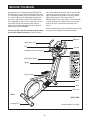
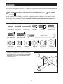
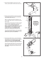
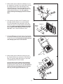
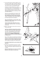
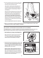
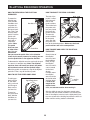
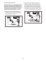
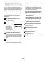
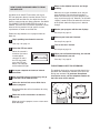
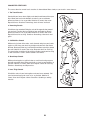
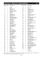
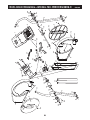
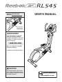
USER'S MANUAL
Model No. RBCCEL5906.0
Serial No.
Serial Number
Decal (on top
of the frame)
QUESTIONS?
As a manufacturer, we are committed to providing complete
customer satisfaction. If you have
questions, or if there are missing
parts, please call:
1-888-936-4266
Mon.–Fri. 8h00 until 17h00 EST
(excluding holidays).
[email protected]
Visit
our website at
www.proform.com
Visit our website at
www.healthrider.com
CAUTION
Visit our website at
www.nordictrack.com
Read all precautions and instructions in this manual before using
Visit
this equipment. Keep this manual
for future reference.
our website at
www.weiderfitness.com
Visit our website at
www.weslo.com
Visit our website at
www.jumpking.com
Visit our website at
www.imagefitness.com
Visit our website at
www.reebokfitness.com
TABLE OF CONTENTS
IMPORTANT PRECAUTIONS . . . . . . . . . . . . . . . . . . . . . . . . . . . . . . . . . . . . . . . . . . . . . . . . . . . . . . . . . . . . . . . .3
BEFORE YOU BEGIN . . . . . . . . . . . . . . . . . . . . . . . . . . . . . . . . . . . . . . . . . . . . . . . . . . . . . . . . . . . . . . . . . . . . . .4
ASSEMBLY . . . . . . . . . . . . . . . . . . . . . . . . . . . . . . . . . . . . . . . . . . . . . . . . . . . . . . . . . . . . . . . . . . . . . . . . . . . . . . .5
ELLIPTICAL EXERCISER OPERATION . . . . . . . . . . . . . . . . . . . . . . . . . . . . . . . . . . . . . . . . . . . . . . . . . . . . . . .10
MAINTENANCE AND TROUBLESHOOTING . . . . . . . . . . . . . . . . . . . . . . . . . . . . . . . . . . . . . . . . . . . . . . . . . . .22
EXERCISE GUIDELINES . . . . . . . . . . . . . . . . . . . . . . . . . . . . . . . . . . . . . . . . . . . . . . . . . . . . . . . . . . . . . . . . . . .23
PART LIST . . . . . . . . . . . . . . . . . . . . . . . . . . . . . . . . . . . . . . . . . . . . . . . . . . . . . . . . . . . . . . . . . . . . . . . . . . . . . .25
EXPLODED DRAWING . . . . . . . . . . . . . . . . . . . . . . . . . . . . . . . . . . . . . . . . . . . . . . . . . . . . . . . . . . . . . . . . . . . .26
ORDERING REPLACEMENT PARTS . . . . . . . . . . . . . . . . . . . . . . . . . . . . . . . . . . . . . . . . . . . . . . . . . .Back Cover
LIMITED WARRANTY . . . . . . . . . . . . . . . . . . . . . . . . . . . . . . . . . . . . . . . . . . . . . . . . . . . . . . . . . . . . . .Back Cover
REEBOK and the Vector Logo
are registered trademarks and service marks of Reebok. This product is
manufactured and distributed under license from Reebok International.
2
IMPORTANT PRECAUTIONS
WARNING:
To reduce the risk of serious injury, read the following important precautions before using the elliptical exerciser.
1. Read all instructions in this manual before
using the elliptical exerciser.
Always hold the handlebar or the upper body
arms when using the elliptical exerciser.
2. It is the responsibility of the owner to ensure
that all users of the elliptical exerciser are
adequately informed of all precautions.
10. Keep your back straight when using the elliptical exerciser; do not arch your back.
11. If you feel pain or dizziness while exercising, stop immediately and cool down.
3. The elliptical exerciser is intended for
in-home use only. Do not use the elliptical
exerciser in a commercial, rental, or institutional setting.
12. The pulse sensor is not a medical device.
Various factors, including the user's movement, may affect the accuracy of heart rate
readings. The pulse sensor is intended only
as an exercise aid in determining heart rate
trends in general.
4. Place the elliptical exerciser on a level surface, with a mat beneath it to protect the
floor or carpet. Keep the elliptical exerciser
indoors, away from moisture and dust.
13. When you stop exercising, allow the pedals
to slowly come to a stop. The elliptical exerciser does not have a free wheel; the pedals
will continue to move until the flywheel
stops.
5. Inspect and properly tighten all parts regularly. Replace any worn parts immediately.
6. Keep children under age 12 and pets away
from the elliptical exerciser at all times.
14. The decal shown on page 4 has been placed
on the elliptical exerciser in the indicated
location. If the decal is missing or illegible,
call the telephone number on the front cover
of this manual and order a free replacement
decal. Apply the replacement decal in the
location shown.
7. The elliptical exerciser should not be used
by persons weighing more than 250 pounds.
8. Wear appropriate exercise clothing when
using the elliptical exerciser. Always wear
athletic shoes for foot protection.
9. Always hold the handlebar when mounting
or dismounting the elliptical exerciser.
WARNING:
Before beginning this or any exercise program, consult your physician.
This is especially important for persons over the age of 35 or persons with pre-existing health problems. Read all instructions before using. ICON assumes no responsibility for personal injury or
property damage sustained by or through the use of this product.
3
BEFORE YOU BEGIN
tions after reading this manual, please see the front
cover of this manual. To help us assist you, please
note the product model number and serial number
before contacting us. The model number is
RBCCEL5906.0. The serial number can be found on
a decal attached to the elliptical exerciser (see the
front cover of this manual for the location of the
decal).
Congratulations for selecting the new REEBOK® RL
545 elliptical exerciser. The RL 545 elliptical exerciser
is an incredibly smooth exerciser that moves your feet
in a natural elliptical path, minimizing the impact on
your knees and ankles. And the unique RL 545 features adjustable resistance and a state-of-the-art console to help you get the most from your exercise.
Welcome to a whole new world of natural, ellipticalmotion exercise from REEBOK.
Before reading further, please familiarize yourself with
the parts that are labeled in the drawing below.
For your benefit, read this manual carefully before
you use the elliptical exerciser. If you have ques-
Bookrack
Upper Body Arm
REV–B
Fan
Console
Handlebar with Pulse Sensor
Water Bottle Holder*
Upright
Pedal Cushion
Wheel
Pedal
Pedal Leg
BACK
RIGHT SIDE
Leveling Foot
*No water bottle is included
4
209
ASSEMBLY
Place all parts of the elliptical exerciser in a cleared area and remove the packing materials. Do not dispose of
the packing materials until assembly is completed.
In addition to the included tools, assembly requires an adjustable wrench
mallet
.
and a rubber
See the drawings below to identify the small parts needed for assembly. The number in parentheses below
each drawing is the key number of the part, from the PART LIST on page 25; the number following the key
number is the quantity needed for assembly. Note: Some small parts may have been preassembled. If a
part is not found in the parts bag, check to see if it has been preassembled.
M4 x 16mm
Screw (82)–6
M4 x 22mm
Screw (92)–2
M8 x 19mm Patch
Screw (81)–4
M10 Nylon
Locknut (85)–4
M4 x 25mm
Screw (69)–2
M6 x 13mm
Shoulder
Screw (93)–2
M8 x 19mm
Shoulder
Screw (86)–2
Bolt Set (67)–2
M8 x 25mm Patch
Screw (73)–10
M6 Split
Washer (72)–2
Small M8
Washer (71)–2
M6 x 20mm Patch
Screw (75)–4
M10 Split
Washer (87)–4
1. Identify the Front Stabilizer (63), which has Wheels
(27) attached to one side. Attach the Front Stabilizer
to the front of the Frame (1) with four M8 x 25mm
Patch Screws (73).
1
73
27
5
Wave Washer
(91)–2
Large M8
Washer (70)–2
73
63
73
1
2. Attach the Rear Stabilizer (24) to the rear of the
Frame (1) with four M8 x 25mm Patch Screws (73).
2
1
73
73
24
3. Remove the four M10 Nylon Locknuts (85) and the
four M10 Split Washers (87) from the welded bolts
near the front of the Frame (1).
3
While a second person holds the Upright (2), connect the Upper Wire Harness (15) to the Lower Wire
Harness (39).
85
87
2
Align the holes in the bracket on the lower end of the
Upright (2) with the welded bolts on the Frame (1).
Lower the Upright, feeding the Upper Wire
Harness (15) and the Lower Wire Harness (39) up
into the Upright, until the welded bolts are fully
inserted into the bracket. Be careful to avoid
pinching and damaging the Wire Harnesses.
Be careful to
avoid pinching
and damaging the
Wire Harnesses
(15, 39) during
this step.
Bracket
15
Place the four M10 Split Washers (87) onto the welded bolts on the Frame (1). Then, tighten the four M10
Nylon Locknuts (85) onto the welded bolts.
4. Feed the Upper Wire Harness (15) up through the
indicated hole in the Console Bracket (3). Attach the
Console Bracket to the Upright (2) with four M8 x
19mm Patch Screws (81). Be careful to avoid
pinching and damaging the Upper Wire Harness.
Attach the Water Bottle Holder (13) to the Upright (2)
with two M4 x 22mm Screws (92). Note: The water
bottle holder is designed to be used with your own
water bottle.
39
1
Welded
Bolts
4
81
3
2
Hole
15
13
92
6
5. While another person holds the Handlebar (4) near
the Upright (2), feed the Pulse Sensor Wire (14) into
the Upright and out of the indicated hole in the
Console Bracket (3). Attach the Handlebar to the
Upright with two M6 x 13mm Shoulder Screws (93)
and two M6 Split Washers (72). Be careful to
avoid pinching and damaging the Pulse Sensor
Wire.
6. The Console (8) requires four “D” batteries (not
included); alkaline batteries are recommended.
Press the indicated tab on the battery cover and
remove the cover. Press four batteries into the battery clips; make sure that the batteries are oriented as shown by the markings inside of the battery clips. Then, reattach the battery cover.
7. Insert the Bookrack (7) into the slots in the Console
(8). Attach the Bookrack to the Console with two M4
x 25mm Screws (69). Be careful to avoid pinching
and damaging the wires in the Console.
5
3
Hole
14
93
72
2
6
Battery
Cover
4
8
Batteries
7
7
8
8. While another person holds the Console (8) near
the Console Bracket (3), connect the Pulse Sensor
Wire (14) and the Upper Wire Harness (15) to the
corresponding wires on the Console.
69
8
Insert all excess wiring down into the Upright
(2). Attach the Console (8) to the Console Bracket
(3) with four M4 x 16mm Screws (82). Be careful to
avoid pinching and damaging the Pulse Sensor
Wire (14) and the Upper Wire Harness (15).
8
82
Console
Wires
15
3
2
7
14
82
9. Insert the Pivot Axle (21) into the Upright (2), and
center the Pivot Axle. Apply a generous amount of
the included grease to both ends of the Pivot Axle
and to the flat side of an Upright Bushing (20).
9
Identify the Left Upper Body Arm (5), which is
marked with a decal. Insert the Upright Bushing (20)
into an Upright Spacer (19). Turn the Upright
Spacer so that the semicircular cutout is at the top,
and slide the Upright Spacer onto the post on the
Left Upper Body Arm.
Slide the Left Upper Body Arm (5) onto the Pivot
Axle (21). Attach a Pivot Spacer (17) to the Left
Upper Body Arm with an M4 x 16mm Screw (82).
Turn a Pivot Endcap (16) so that the rectangular
cutout is at the bottom. Using a rubber mallet, tap
the Pivot Endcap into the Pivot Spacer.
5
17
16
71
86
19
20
Post
2
21
Grease
6
82
Slide a Small M8 Washer (71) onto an M8 x 19mm
Shoulder Screw (86), and finger tighten the Shoulder
Screw into the Pivot Axle (21).
Attach the Right Upper Body Arm (6) in the
same manner. Tighten both M8 x 19mm Shoulder
Screws (86).
10. Apply a small amount of grease to the axle on the
left Crank Arm (40).
10
Identify the Left Pedal Leg (28), which is marked
with a decal. Slide the Left Pedal Leg onto the axle
on the left Crank Arm (40). Slide a Wave Washer
(91) and a Large M8 Washer (70) onto an M8 x
25mm Patch Screw (73), and tighten the Patch
Screw into the axle. Make sure that the Wave
Washer is on the end of the axle before tightening
the Patch Screw.
74
28
Snap a Pedal Cushion (74) around the Left Pedal Leg
(28) onto a Cushion Bracket (46). Make sure that the
arrow on the Pedal Cushion is pointing to one of the
numbers on the Left Pedal Leg and that the number
shows through the window in the Cushion Bracket.
Assemble the Right Pedal Leg (not shown) in the
same way.
11. Identify the Left Pedal Arm (33), which is marked
with a decal. Attach the Left Pedal (35) to the Left
Pedal Arm with two M6 x 20mm Patch Screws (75)
as shown.
Window
73 70
75
33
Attach the Right Pedal (not shown) to the Right
Pedal Arm (not shown) in the same way.
8
40
46
11
Grease
91
35
12. Set the Left Pedal Arm (33) on the left Pedal Cushion
(74), and hold the end of the Left Pedal Arm inside of
the bracket on the Left Pedal Leg (28).
12
Hold a Plastic Pedal Arm Spacer (65) between the
Left Pedal Leg (28) and the Left Pedal Arm (33).
Insert the long part of a Bolt Set (67) through the Left
Pedal Leg, the Plastic Pedal Arm Spacer, and the
Left Pedal Arm.
5
Apply a film of the included grease to the long part of
the Bolt Set (67). Lift the Left Pedal Leg (28), and
hold the lower end of the Left Upper Body Arm (5)
inside of the bracket on the Left Pedal Arm (33).
Insert the long part of the Bolt Set through the Left
Upper Body Arm. Hold another Plastic Pedal Arm
Spacer (65) between the Left Pedal Arm and the Left
Pedal Leg, and insert the long part of the Bolt Set
through these parts. Tighten the short part of the Bolt
Set into the long part.
65
65
67
32
33
67
Grease
28
74
Attach the Right Pedal Arm (32) in the same way.
13. Make sure that all parts are properly tightened before you use the elliptical exerciser. Note: Some
hardware may be left over after assembly is completed.
HOW TO INSTALL THE RECEIVER FOR THE OPTIONAL CHEST PULSE SENSOR
The elliptical exerciser is now fully assembled. If you purchase the optional chest pulse sensor (see
page 21), follow the steps below to install the receiver included with the chest pulse sensor.
1. See assembly step 7 on page 7, and remove the two
M4 x 25mm Screws (not shown) and the Bookrack (7).
Next, look under the Console (8) and locate the three
indicated screws (not shown). Remove the three
screws. Do not remove the screws attaching the
Console to the Console Bracket (not shown).
2. Carefully lift the top of the Console (8) as shown. Using
the two small screws included with the chest pulse sensor, attach the receiver to the indicated plastic posts on
the Console. Make sure that the receiver is turned
exactly as shown. Connect the wire on the receiver to
the indicated wire on the Console.
See step 1 above. Lower the top of the Console (8).
Make sure that no wires are pinched. Reattach the
top of the Console with the three screws removed in
step 1. See assembly step 7 on page 7, and reattach
the Bookrack (7) with the two M4 x 25mm Screws (not
shown). Note: The remaining wires included with the
chest pulse sensor may be discarded.
9
1
7
8
Screws
2
8
Screws
Wire
Receiver
Posts
ELLIPTICAL EXERCISER OPERATION
HOW TO EXERCISE ON THE ELLIPTICAL
EXERCISER
To mount the
elliptical exerciser, hold the
Handlebar
handlebar and
step onto the
pedal that is in
the lowest position. Then, step
onto the other
Pedals
pedal. Push the
pedals until
they begin to
move with a
continuous
motion. Note:
The pedal
disks can turn
Pedal Disk
in either direction. It is recommended
that you move the pedal disks in the direction
shown by the arrow; however, for variety, you can
turn the pedal disks in the opposite direction.
To dismount the elliptical exerciser, wait until the pedals come to a complete stop. Note: The elliptical
exerciser does not have a free wheel; the pedals
will continue to move until the flywheel stops.
When the pedals are stationary, step off the highest
pedal first. Then, step off the lowest pedal.
HOW TO USE THE UPPER BODY ARMS
To add upperbody exercise
to your workouts, push and
pull the upper
body arms as
you exercise.
To exercise
only your lower
body, hold the
handlebar as
you exercise.
Upper Body Arms
HOW TO ADJUST THE PEDAL CUSHIONS
The feel of the
pedals is affectPedal
ed by the posiArm
tions of the
pedal cushions.
The farther back
the pedal cushions are placed,
the firmer the
pedals will feel.
To move the
Pedal Cushion
pedal cushions,
(under the pedal)
lift the pedal
arms and slide
the pedal cushions to the desired positions. Make sure that both
pedal cushions are in the same position.
HOW TO MOVE AND LEVEL THE ELLIPTICAL
EXERCISER
Stand in front of
the elliptical
exerciser, hold
the handlebar
firmly, and tip
the elliptical
exerciser until it
Handlebar
can be moved
on the front
wheels.
Carefully move
the elliptical
exerciser to the
Wheel
desired location
Leveling
and then lower
Foot
it. Due to the
weight of the
elliptical exerciser, use extreme caution when moving it.
After the elliptical exerciser has been moved, make
sure that the ends of both stabilizers are touching the
floor. If the elliptical exerciser rocks slightly during use,
turn one or both of the leveling feet under the front stabilizer until the rocking motion is eliminated.
10
Note: If there is a sheet of clear plastic on
the face of the console, remove the plastic.
FEATURES OF THE CONSOLE
ing a personal trainer in your home. Using the included
audio cable, you can connect the elliptical exerciser to
your home stereo, portable stereo, computer, or VCR
and play special iFIT.com CD and video programs
(iFIT.com CDs and videocassettes are available separately). iFIT.com CD and video programs automatically
control the resistance of the pedals and prompt you to
vary your pace as a personal trainer coaches you
through every step of your workout. High-energy music
provides added motivation. To purchase iFIT.com CDs
and videocassettes, call the telephone number on
the front cover of this manual.
The advanced console offers a selection of features
designed to make your workouts more enjoyable and
effective. When the manual mode of the console is
selected, the resistance of the pedals can be changed
with the touch of a button. As you exercise, the console will provide continuous exercise feedback. You
can even measure your heart rate using the handgrip
pulse sensor. Note: See page 21 for information
about an optional chest pulse sensor.
The console also offers six preset programs. Each program automatically changes the resistance of the pedals and prompts you to increase or decrease your pace
as it guides you through an effective workout.
With the elliptical exerciser connected to your computer, you can also go to our Web site at www.iFIT.com
and access programs directly from the internet.
Explore www.iFIT.com for more information.
In addition, the console features two heart rate programs that automatically change the resistance of the
pedals and prompt you to vary your pace to keep your
heart rate near a target heart rate as you exercise.
To use the manual mode of the console, see page
12. To use a preset program, see page 14. To use a
heart rate program, see page 15. To use an
iFIT.com CD or videocassette, see page 20. To use
a program directly from our Web site, see page 21.
The console also features iFIT.com interactive technology. Having iFIT.com interactive technology is like hav-
11
The upper
display—The
upper display will
show the elapsed
time and the total
number of revolutions you have pedaled. The display will change from one number to
the next every few seconds, as shown by the indicators in the display. Note: When a program is
selected, the display will show the time remaining
in the program instead of the elapsed time. Each
time the resistance of the pedals changes, the
display will show the resistance level.
HOW TO USE THE MANUAL MODE
1
2
3
4
Begin pedaling to activate the console.
To activate the console, begin pedaling or push
any button on the console. After a few seconds,
the console displays will light. A tone will then
sound and the console will be ready for use.
Select the manual mode.
When the power is
turned on, the
manual mode will
be selected. If you
have selected a
program or the
iFIT.com mode,
select the manual mode by pressing the Program
Select button repeatedly until a track appears in
the matrix.
If desired, you can
select a single
mode for continuous display. Press
the left Mode button
repeatedly until the
desired mode indicator is lit; make sure that the Scan indicator is
not lit.
Begin pedaling and change the resistance of
the pedals as desired.
The lower
display—The lower
display will show
the approximate
number of calories
you have burned
and your pedaling
pace, in revolutions per minute (RPM). The display will change from one number to the next
every few seconds, as shown by the indicators in
the display. The display will also show your heart
rate when you use the handgrip pulse sensor or
the optional chest pulse sensor.
As you pedal,
change the resistance of the pedals by pressing the
Resistance buttons. There are
ten resistance levels. Note: After the buttons are pressed, it will
take a moment for the pedals to reach the selected resistance level.
Monitor your progress with the matrix and the
two displays.
If desired, you can select a single mode for continuous display. Press the right Mode button
repeatedly until the desired mode indicator is lit;
make sure that the Scan indicator is not lit.
The matrix—
When the manual
mode or the
iFIT.com mode is
selected, the
matrix will show a
track representing
1/4 mile. As you exercise, the indicators around
the track will light, one at a time, until the entire
track is lit. The track will then darken and a new
lap will begin.
12
5
Note: If you continue to hold the pulse sensor, the
lower display will show your heart rate for up to
30 seconds. The display will then show your heart
rate along with the other modes.
Measure your heart rate if desired.
You can measure your heart rate using either
the handgrip pulse sensor or the optional
chest pulse sensor. Note: If you hold the
handgrip pulse sensor and wear the chest
pulse sensor at the same time, the console
will not display your heart rate accurately.
If there are
thin sheets of
plastic on the
metal contacts on the
handgrip
pulse sensor,
Contacts
peel off the
plastic. To
measure your
heart rate, hold the contacts; your palms must be
resting on the contacts closest to you, and your
fingers must be touching the opposite contacts.
Avoid moving your hands.
6
7
When your pulse
is detected, the
heart-shaped indicator in the lower
display will flash
each time your
heart beats, and
your heart rate will be shown. For the most accurate heart rate reading, hold the contacts for at
least 15 seconds.
If your heart rate is not shown, make sure that
your hands are positioned as described. Avoid
moving your hands excessively or squeezing the
metal contacts too tightly. For optimal performance,
periodically clean the metal contacts using a soft
cloth; never use alcohol, abrasives, or chemicals.
Turn on the fan if desired.
To turn on the fan at low speed, press the
Variable Speed Fan button. To turn on the fan at
high speed, press the button a second time. To
turn off the fan, press the button a third time.
Note: If the fan is turned on but the pedals are not
moved for thirty seconds, the fan will automatically
turn off.
When you are finished exercising, the console
will automatically turn off.
If the pedals are not moved for a few seconds, a
tone will sound, the console will pause, and the
upper display will begin to flash.
If the pedals are not moved for about five minutes, the console will turn off and the displays will
be reset.
13
The program will continue until the resistance setting for the last segment is shown in the Current
Segment column of the matrix and no time
remains in the program.
HOW TO USE PRESET PROGRAMS
1
2
3
Begin pedaling to activate the console.
See step 1 on page 12.
Select one of the six preset programs.
When the power is
turned on, the
manual mode will
be selected. To
select a preset
program, press the
Program Select
button repeatedly until “P1,” “P2,” “P3,” “P4,”
“P5,” or “P6” appears in the lower display.
4
When a preset program is selected, the matrix
will show the first six resistance settings of the
program.
Press the Program Start button or begin
pedaling to start the program.
Each program is divided into several time segments of different lengths. One resistance setting
is programmed for each segment. (The same
resistance setting may be programmed for two or
more consecutive segments.)
The resistance
Current Segment
setting for the first
segment will be
shown in the flashing Current
Segment column
of the matrix. The
resistance settings
for the next five
segments will be shown in the columns to the
right.
5
6
7
When only three seconds remain in the first segment of the program, a series of tones will sound;
all resistance settings will then move one column
to the left. The resistance setting for the second
segment will then be shown in the flashing
Current Segment column and the resistance of
the pedals will automatically change to the resistance setting for the second segment.
8
14
Note: During the program, you can override the
resistance setting for the current segment by
pressing the Resistance buttons. However, when
the next segment begins, the resistance will automatically change if a different resistance setting is
programmed for the next segment. If you stop
pedaling for several seconds, a tone will sound
and the program will pause. To restart the program, simply resume pedaling.
Use the pace (RPM) guide.
During preset programs, the pace
guide will prompt
you to increase or
decrease your pedaling pace. When
one of the indicators on the left side
of the pace guide
lights, increase
your pace; when
one of the indicators on the right side lights, decrease your pace.
When the center indicator lights, maintain your
current pace. Important: The pace settings of
the program are intended only to provide a
goal. Make sure to pedal at a pace that is
comfortable for you.
Monitor your progress with the two displays.
See step 4 on page 12.
Measure your heart rate if desired.
See step 5 on page 13.
Turn on the fan if desired.
See step 6 on page 13.
When you are finished exercising, the console
will automatically turn off.
See step 7 on page 13.
HOW TO USE HEART RATE PROGRAMS
Heart rate program 1 is designed to keep your heart
rate between 60% and 85% of your estimated maximum heart rate while you exercise. Note: Your maximum heart rate is estimated by subtracting your age
from 220. For example, if you are 30 years old, your
estimated maximum heart rate is 190 (220 – 30 =
190).
3
Enter your age.
4
Enter a target heart rate.
Heart rate program 2 will keep your heart rate near a
target heart rate that you select.
Follow the steps below to use a heart rate program.
1
2
Begin pedaling to activate the console.
See step 1 on page 12.
Select one of the heart rate programs.
To select a heart
rate program,
press the Program
Select button
repeatedly until
“H1” or “H2”
appears in the
lower display.
If you selected
heart rate program
1, the matrix will
show the first eight
target heart rate
settings of the program.
5
If you selected
heart rate program
2, a heart symbol
will appear in the
matrix.
If you selected heart rate program 1, go to
step 3. If you selected heart rate program 2,
go to step 4.
15
When heart rate
program 1 is
selected, you must
enter your age. If
you have already
entered your age,
press the Enter
(Program Start)
button and go to
step 5. If you have
not entered your
age, press the + or
– button repeatedly to enter your age, and then
press the Enter button. Note: Once you have
entered your age, it will be saved in memory.
When heart rate
program 2 is
selected, you must
enter a target heart
rate. (See the heart
rate chart on page
23 for heart rate
guidelines.) To
enter a target heart
rate, press the + or
– button repeatedly, and then press
the Enter button.
Hold the handgrip pulse sensor or wear the
optional chest pulse sensor.
To use a heart rate program, you must hold the
handgrip pulse sensor or wear the optional chest
pulse sensor. If you use the handgrip pulse sensor, it is not necessary to hold the handgrips continuously during the program. However, you
should hold the handgrips frequently for the program to operate properly. Each time you hold
the handgrips, keep your hands on the metal
contacts for at least 30 seconds. Note: When
you are not holding the handgrips, the letters
“PLS” will appear in the lower display instead of
your heart rate.
6
Begin pedaling.
The pace guide
will help you to
maintain a constant pace during
the program. When
one of the indicators on the left side
of the pace guide
lights, increase
your pace; when
one of the indicators on the right
side lights, decrease your pace. When the center
indicator lights, maintain your current pace.
Important: The pace settings of the program
are intended only to provide a goal. Make
sure to pedal at a pace that is comfortable for
you.
Each heart rate program is divided into 30 oneminute segments. One target heart rate is programmed for each segment. Note: The same target heart rate may be programmed for two or
more consecutive segments. If heart rate program 2 is selected, the same target heart rate is
programmed for all segments.
If heart rate proCurrent Segment
gram 1 is selected, the target
heart rate setting
for the first segment will be
shown in the
flashing Current
Segment column
of the matrix. The target heart rate settings for the
next seven segments will be shown in the
columns to the right. When only three seconds
remain in the first segment of the program, both
the Current Segment column and the column to
the right will flash, a series of tones will sound,
and the time will flash in the right display. When
the first segment ends, all target heart rate settings will move one column to the left. The target
heart rate setting for the second segment will
then be shown in the flashing Current Segment
column.
The program will continue until no time remains
in the right display.
7
If heart rate program 2 is selected, the same
target heart rate is programmed for all segments;
therefore, the target heart rate settings will not be
shown in the matrix. When only three seconds
remain in the first segment of the program, a
series of tones will sound and the time will flash
in the right display.
8
9
As you pedal, the console will regularly compare
your heart rate to the target heart rate. If your
heart rate is too far below or above the target
heart rate, the resistance of the pedals will automatically increase or decrease to being your heart
rate closer to the target heart rate.
16
Note: During the program, you can manually
change the resistance setting, if desired, by
pressing the Resistance buttons. However, when
the console compares your heart rate to the target heart rate, the resistance may automatically
change. If you stop pedaling for several seconds,
a tone will sound and the program will pause. To
restart the program, simply resume pedaling.
Monitor your progress with the two displays.
See step 4 on page 12.
Turn on the fan if desired.
See step 6 on page 13.
When you are finished exercising, the console will automatically turn off.
See step 7 on page 13.
HOW TO CONNECT YOUR PORTABLE STEREO
HOW TO CONNECT YOUR CD PLAYER, VCR,
OR COMPUTER
Note: If your stereo has an RCA-type AUDIO OUT
jack, see instruction A below. If your stereo has a
1/8” LINE OUT jack, see instruction B. If your
stereo has only a PHONES jack, see instruction C.
To use iFIT.com CDs, the elliptical exerciser must be
connected to your portable CD player, portable stereo,
home stereo, or computer with CD player. See pages
17 and 18 for connecting instructions. To use iFIT.com
videocassettes, the elliptical exerciser must be connected to your VCR. See page 19 for connecting
instructions. To use iFIT.com programs directly from
our Web site, the elliptical exerciser must be connected to your home computer. See page 18 for connecting instructions.
A. Plug one end of the audio cable into theAUDIO
jack
OUT
beneath the console. Plug the other endRIGHTof the cable
into the adapter. Plug the adapter into anLEFTAUDIO
OUT jack on your stereo.
A, B
HOW TO CONNECT YOUR PORTABLE CD PLAYER
A
Note: If your CD player has separate LINE OUT and
PHONES jacks, see instruction A below. If your CD
player has only one jack, see instruction B.
A. Plug one end of the audio cable into the jack
beneath the console. Plug the other end of the
cable into the LINE OUT jack on your CD player.
Plug your headphones into the PHONES jack.
A
PHONES LINE OUT
LINE OUT
PHONES LINE OUT
LINE OUT
PHONES
PHONES
Headphones
Audio
Cable
A
A
Audio Cable
Audio
Cable
LINE OUT
C. Plug one end of the audio cable into the jack
beneath the console. Plug the other end of the
cable into a 1/8” Y-adapter (available at electronics
stores). Plug the Y-adapter into the PHONES jack
on your stereo. Plug your headphones into the
other side of the Y-adapter.
B
C
B
Audio
Cable
LINE OUT
C
PHONES
1/8”
Y-adapter
PHONES
17
C
PHONES
1/8”
Y-adapter
Headphones
Headphones
B
B
Adapter
A
PHONES
PHONES
LEFT
B. Plug one end of the audio cable into the jack
beneath the console. Plug the other end of the
cable into the LINE OUT jack on your stereo. Do
not use the adapter.
B. Plug one end of the audio cable into the jack
beneath the console. Plug the other end of the
cable into a 1/8” Y-adapter (available at electronics
stores). Plug the Y-adapter into the PHONES jack
on your CD player. Plug your headphones into the
other side of the Y-adapter.
B
AUDIO OUT
RIGHT
PHONES
HOW TO CONNECT YOUR HOME STEREO
HOW TO CONNECT YOUR COMPUTER
A. Plug one end of the audio cable into the jack
beneath the console. Plug the other end of the
cable into the adapter. Plug the adapter into the
LINE OUT jack on your stereo.
A. Plug one end of the audio cable into the jack
beneath the console. Plug the other end of the
cable into the LINE OUT jack on your computer.
Note: If your stereo has an unused LINE OUT jack,
see instruction A below. If the LINE OUT jack is
being used, see instruction B.
A
Note: If your computer has a 1/8” LINE OUT jack,
see instruction A. If your computer has only a
PHONES jack, see instruction B.
A
CD
VCR
Amp
LINE OUT
CD
Audio
Cable
VCR
LINE OUT
LINE OUT
LINE OUT
Audio
Cable
A
Amp
Adapter
LINE OUT
LINE OUT
A
B. Plug one end of the audio cable into the jack
beneath the console. Plug the other end of the
cable into a 1/8” Y-adapter (available at electronics
stores). Plug the Y-adapter into the PHONES jack
on your computer. Plug your headphones or speakers into the other side of the Y-adapter.
A
B. Plug one end of the audio cable into the jack
beneath the console. Plug the other end of the
cable into the adapter. Plug the adapter into an
RCA Y-adapter (available at electronics stores).
Next, remove the wire that is currently plugged into
the LINE OUT jack on your stereo and plug the
wire into the unused side of the Y-adapter. Plug the
Y-adapter into the LINE OUT jack on your stereo.
A
B
PHONES
PHONES
CD
VCR
B
Amp
CD
Audio
Cable
VCR
LINE OUT
Amp
B
Adapter
B
B
Headphones/Speakers
LINE OUT
RCA
Y-adapter
Audio
Cable
1/8”
Y-adapter
Wire removed from
LINE OUT jack
B
18
HOW TO CONNECT YOUR VCR
B. Plug one end of the audio cable into the jack
beneath the console. Plug the other end of the
cable into the adapter. Plug the adapter into an
RCA Y-adapter (available at electronics stores).
Next, remove the wire that is currently plugged into
the AUDIO OUT jack on your VCR and plug the
wire into the unused side of the Y-adapter. Plug the
Y-adapter into the AUDIO OUT jack on your VCR.
Note: If your VCR has an unused AUDIO OUT jack,
see instruction A below. If the AUDIO OUT jack is
being used, see instruction B. If you have a TV
with a built-in VCR, see instruction B. If your VCR
is connected to your home stereo, see HOW TO
CONNECT YOUR HOME STEREO on page 18.
A
A. Plug one end of the audio cable into the jack
beneath the console. Plug the other end of the
cable into the adapter. Plug the adapter into the
AUDIO OUT jack on your VCR.
A
VIDEO AUDIO
IN
OUT
B
OUT
AUDIO OUT
LEFT
Wire removed from
AUDIO OUT jack
B
Audio Cable
A
VIDEO AUDIO
IN
OUT
AUDIO OUT
ANT. IN
CH
3 4
RF OUT
Adapter
Audio Cable
RF OUT
RIGHT
Adapter
ANT. IN
CH
3 4
RCA Y-adapter
ANT. IN
CH
3 4
VIDEO AUDIO
IN
RF OUT
RIGHT
LEFT
C
B
AUDIO OUT
RIGHT
LEFT
19
your workout. Simply follow your personal trainer’s
instructions.
HOW TO USE IFIT.COM CD AND VIDEO
PROGRAMS
The program will function in almost the same way
as a preset program (see steps 3 and 4 on page
14). However, an electronic “chirping” sound will
alert you when the resistance of the pedals and/or
the target pace is about to change.
To use iFIT.com CDs or videocassettes, the elliptical
exerciser must be connected to your portable CD player, portable stereo, home stereo, computer with CD
player, or VCR. See HOW TO CONNECT YOUR CD
PLAYER, VCR, OR COMPUTER on pages 17 to 19.
To purchase iFIT.com CDs and videocassettes, call
the telephone number on the front cover of this
manual
Note: If the resistance of the pedals and/or the
target pace does not change when a “chirp” is
heard:
• Make sure that the indicator above the
iFIT.com button is lit.
Follow the steps below to use an iFIT.com CD or
video program.
1
2
3
4
• Adjust the volume of your CD player or VCR.
If the volume is too high or too low, the console may not detect the program signals.
Begin pedaling to activate the console.
See step 1 on page 12.
Select the iFIT.com mode.
5
When the console is
turned on, the manual mode will be
selected. To select
the iFIT.com mode,
press the iFIT.com
button. The indicator
on the button will light.
6
7
Insert the iFIT.com CD or videocassette.
If you are using an iFIT.com CD, insert the CD
into your CD player. If you are using an iFIT.com
videocassette, insert the videocassette into your
VCR.
8
Press the play button on your CD player or
VCR.
A moment after the play button is pressed, your
personal trainer will begin guiding you through
20
• Make sure that the audio cable is properly
connected and that it is fully plugged in.
Monitor your progress with the two displays.
See step 4 on page 12.
Measure your heart rate if desired.
See step 5 on page 13.
Turn on the fan if desired.
See step 6 on page 13.
When you are finished exercising, the console
will automatically turn off.
See step 7 on page 13.
HOW TO USE PROGRAMS DIRECTLY FROM
OUR WEB SITE
Our Web site at www.iFIT.com allows you to play
iFIT.com programs directly from the internet. To use
programs from our Web site, the elliptical exerciser
must be connected to your home computer. See HOW
TO CONNECT YOUR COMPUTER on page 18. In
addition, you must have an internet connection and an
internet service provider. A list of specific system
requirements is found on our Web site.
Follow the steps below to use a program from our
Web site.
1
2
See step 1 on page 12.
Follow the desired links on our Web site to
select a program.
6
Follow the on-line instructions to start the
program.
Monitor your progress with the two displays.
See step 4 on page 12.
Measure your heart rate if desired.
See step 5 on page 13.
See step 6 on page 13.
When the console is
turned on, the manual mode will be
selected. To select
the iFIT.com mode,
press the iFIT.com
button. The indicator
on the button will light.
5
4
8
When the on-screen countdown ends, the program will begin. The program will function in
almost the same way as a preset program (see
steps 3 and 4 on page 14). However, an electronic
“chirping” sound will alert you when the resistance
of the pedals and/or the target pace is about to
change.
10 Turn on the fan if desired.
Select the iFIT.com mode.
Go to your computer and start an internet
connection.
Return to the elliptical exerciser and begin
pedaling.
9
Begin pedaling to activate the console.
3
7
you are finished exercising, the console
11 When
will automatically turn off.
See step 7 on page 13.
THE OPTIONAL CHEST PULSE SENSOR
The optional chest pulse sensor provides hands-free
operation and continuously monitors your heart rate
during your workouts. To purchase the optional
chest pulse sensor, call the telephone number on
the front cover of this manual.
Start your Web browser, if necessary, and go
to our Web site at www.iFIT.com.
Read and follow the on-line instructions for using
a program.
When you start the program, an on-screen countdown will begin.
21
MAINTENANCE AND TROUBLESHOOTING
HOW TO LEVEL THE ELLIPTICAL EXERCISER
Inspect and properly tighten all parts of the elliptical
exerciser regularly. The elliptical exerciser can be
cleaned with a soft, damp cloth. To prevent damage to
the console, keep liquids away from the console and
keep the console out of direct sunlight.
If the elliptical exerciser does not sit
flat on the floor,
turn one or both of
the leveling pads
until the elliptical
exerciser is level.
TIGHTENING THE PEDALS
For best performance, regularly tighten both pedals.
CONSOLE TROUBLESHOOTING
If the console display becomes dim, or if the console
does not function properly, the batteries should be
replaced. See assembly step 6 on page 7 for replacement instructions. If the console does not display your
heart rate when you use the handgrip pulse sensor,
see step 5 on page 13.
22
Leveling
Pads
EXERCISE GUIDELINES
Fat Burning
WARNING:
To burn fat effectively, you must exercise at a relatively low intensity level for a sustained period of time.
During the first few minutes of exercise, your body
uses easily accessible carbohydrate calories for energy. Only after the first few minutes of exercise does
your body begin to use stored fat calories for energy. If
your goal is to burn fat, adjust the intensity of your
exercise until your heart rate is near the lowest number or the middle number in your training zone as you
exercise.
• Before beginning this or any exercise program, consult your physician. This is especially important for individuals over the
age of 35 or individuals with pre-existing
health problems.
• The pulse sensor is not a medical device.
Various factors may affect the accuracy of
heart rate readings. The pulse sensor is
intended only as an exercise aid in determining heart rate trends in general.
Aerobic Exercise
If your goal is to strengthen your cardiovascular system, your exercise must be “aerobic.” Aerobic exercise
is activity that requires large amounts of oxygen for
prolonged periods of time. This increases the demand
on the heart to pump blood to the muscles, and on the
lungs to oxygenate the blood. For aerobic exercise,
adjust the intensity of your exercise until your heart
rate is near the highest number in your training zone.
The following guidelines will help you to plan your
exercise program. Remember that proper nutrition and
adequate rest are essential for successful results.
EXERCISE INTENSITY
Whether your goal is to burn fat or to strengthen your
cardiovascular system, the key to achieving the
desired results is to exercise with the proper intensity.
The proper intensity level can be found by using your
heart rate as a guide. The chart below shows recommended heart rates for fat burning, maximum fat burning, and cardiovascular (aerobic) exercise.
WORKOUT GUIDELINES
Each workout should include the following three parts:
A warm-up, consisting of 5 to 10 minutes of stretching
and light exercise. A proper warm-up increases your
body temperature, heart rate, and circulation in preparation for exercise.
Training zone exercise, consisting of 20 to 30 minutes of exercising with your heart rate in your training
zone. (During the first few weeks of your exercise program, do not keep your heart rate in your training
zone for longer than 20 minutes.)
A cool-down, with 5 to 10 minutes of stretching. This
will increase the flexibility of your muscles and will
help to prevent post-exercise problems.
To find the proper heart rate for you, first find your age
at the bottom of the chart (ages are rounded off to the
nearest ten years). Next, find the three numbers above
your age; the three numbers are your “training zone.”
The lowest number is the recommended heart rate for
fat burning; the middle number is the recommended
heart rate for maximum fat burning; and the highest
number is the heart rate for aerobic exercise.
EXERCISE FREQUENCY
To maintain or improve your condition, plan three workouts each week, with at least one day of rest between
workouts. After a few months of regular exercise, you
may complete up to five workouts each week, if
desired. The key to success is make exercise a regular and enjoyable part of your everyday life.
23
SUGGESTED STRETCHES
The correct form for several basic stretches is shown below. Move slowly as you stretch—never bounce.
1. Toe Touch Stretch
1
Stand with your knees bent slightly and slowly bend forward from your
hips. Allow your back and shoulders to relax as you reach down
toward your toes as far as possible. Hold for 15 counts, then relax.
Repeat 3 times. Stretches: Hamstrings, back of knees and back.
2. Hamstring Stretch
Sit with one leg extended. Bring the sole of the opposite foot toward
you and rest it against the inner thigh of your extended leg. Reach
toward your toes as far as possible. Hold for 15 counts, then relax.
Repeat 3 times for each leg. Stretches: Hamstrings, lower back and
groin.
2
3. Calf/Achilles Stretch
With one leg in front of the other, reach forward and place your hands
against a wall. Keep your back leg straight and your back foot flat on
the floor. Bend your front leg, lean forward and move your hips toward
the wall. Hold for 15 counts, then relax. Repeat 3 times for each leg.
To cause further stretching of the achilles tendons, bend your back leg
as well. Stretches: Calves, achilles tendons and ankles.
3
4
4. Quadriceps Stretch
With one hand against a wall for balance, reach back and grasp one
foot with your other hand. Bring your heel as close to your buttocks as
possible. Hold for 15 counts, then relax. Repeat 3 times for each leg.
Stretches: Quadriceps and hip muscles.
5. Inner Thigh Stretch
Sit with the soles of your feet together and your knees outward. Pull
your feet toward your groin area as far as possible. Hold for 15
counts, then relax. Repeat 3 times. Stretches: Quadriceps and hip
muscles.
24
5
PART LIST—MODEL NO. RBCCEL5906.0
Key No. Qty.
1
2
3
4
5
6
7
8
9
10
11
12
13
14
15
16
17
18
19
20
21
22
23
24
25
26
27
28
29
30
31
32
33
34
35
36
37
38
39
40
41
42
43
44
45
46
47
48
49
50
51
52
53
54
55
1
1
1
1
1
1
1
1
2
1
1
2
1
1
1
2
2
6
2
2
1
2
4
1
4
4
2
1
4
4
2
1
1
1
1
2
2
2
1
2
1
2
2
1
2
2
1
1
1
1
2
1
1
2
1
Description
Frame
Upright
Console Bracket
Handlebar
Left Upper Body Arm
Right Upper Body Arm
Bookrack
Console
Pedal Disk
Left Side Shield
Right Side Shield
Foam Grip
Water Bottle Holder
Hand Pulse Sensor/Wire
Upper Wire Harness
Pivot Endcap
Pivot Spacer
Pivot Bushing
Upright Spacer
Upright Bushing
Pivot Axle
Upper Body Endcap
Upper Body Bushing
Rear Stabilizer
Stabilizer Endcap
Foot
Wheel
Left Pedal Leg
Pedal Leg Bushing
Pedal Arm Endcap
Pedal Leg Endcap
Right Pedal Arm
Left Pedal Arm
Right Pedal
Left Pedal
Short Crank Bushing
Long Crank Bushing
Frame Endcap
Lower Wire Harness
Crank Arm
Pulley
Crank Block
Crank Block Set
Crank Spacer
Selector Plate
Cushion Bracket
Resistance Motor
Resistance Cable
Flywheel
Magnet
Flywheel Snap Ring
Pulley Axle
“C” Magnet
Pillow Block Set
Pulley Axle Bushing
Key No. Qty.
56
57
58
59
60
61
62
63
64
65
66
67
68
69
70
71
72
73
74
75
76
77
78
79
80
81
82
83
84
85
86
87
88
89
90
91
92
93
94
95
96
97
98
99
100
101
102
103
104
105
106
#
#
#
1
1
1
1
1
1
2
1
1
4
1
2
8
2
2
4
2
10
2
4
1
1
7
2
9
4
28
2
1
6
2
4
1
4
4
2
2
2
1
4
1
1
2
1
1
2
2
4
1
1
2
4
1
1
R0606A
Description
Small Pulley
Belt
Idler Pulley
Reed Switch Clamp
Reed Switch/Wire
Idler Pulley Bracket
Bumper
Front Stabilizer
Idler Bolt
Plastic Pedal Arm Spacer
M6 x 8mm Screw
Bolt Set
M6 x 32mm Flat Head Bolt
M4 x 25mm Screw
Large M8 Washer
Small M8 Washer
M6 Split Washer
M8 x 25mm Patch Screw
Pedal Cushion
M6 x 20mm Patch Screw
Set Screw
Spring
M5 x 16mm Bolt
M10 x 51mm Button Bolt
M6 Nylon Locknut
M8 x 19mm Patch Screw
M4 x 16mm Screw
Stop Nut
Stop Bolt
M10 Nylon Locknut
M8 x 19mm Shoulder Screw
M10 Split Washer
Right Pedal Leg
M5 Washer
M5 Nylon Locknut
Wave Washer
M4 x 22mm Screw
M6 x 13mm Shoulder Screw
M4 x 63mm Screw
M5 x 28mm Screw
M4 x 10mm Flat Head Screw
Reed Switch Plate
Flange Screw
M4 x 12mm Screw
Magnet Bracket Bolt
M8 x 55mm Button Screw
M8 x 47mm Button Screw
M6 x 10mm Button Screw
Flywheel Spacer
M6 Washer
Snap Ring
Hex Key
Grease
User’s Manual
Note: “#” indicates a non-illustrated part. Specifications are subject to change without notice. See the back cover
of this manual for information about ordering replacement parts.
25
95
95
86
26
71
16
10
23
82
17
9
18
82
23
5
18
82
19
22
20
12
18
2
82
82
85
13
3
82
87
92
72
81
93
81
11
4
72
94
14
15
18
82
78
21
69
82
20
78
7
95
19
8
9
18
22
95
18
23
6
17 82
86
16 71
EXPLODED DRAWING—MODEL NO. RBCCEL5906.0
R0606A
27
30
43
67
65
31
25
82
79
27
85
82
26
65
82
33
67
41
101
71
63
27
45
82
25
49
46
74
82
73
28
62
82
60
59
50
78
89
106
68
68
42
96 97
90
70 91
98
30
39
73
99
1
103
76 104
54
73 51
103
56
73
26
101
35
75
71
102
38
82
102
73
79
29
29
40
52
25
89
47
78
58
66
103
51
53
36
82
36
37
80
37
73
83
61
64
100 77
83
54
103
26
84
105
80
31
67
82
73
65
30
24
82
73
65
26
43
44
45
80
80
82
82
82
42
40
46
25
38
32
74
55
73
82
67
34
48
106
98
88
68
68
62
30
75
57
29
73
91
70
ORDERING REPLACEMENT PARTS
To order replacement parts, please see the front cover of this manual. To help us assist you, please be prepared
to give the following information when contacting us:
• the MODEL NUMBER of the product (RBCCEL5906.0)
• the NAME of the product (REEBOK RL 545 elliptical exerciser)
• the KEY NUMBER and DESCRIPTION of the part(s) (see the PART LIST on page 25)
LIMITED WARRANTY
ICON of Canada, Inc. (ICON), warrants this product to be free from defects in workmanship and material,
under normal use and service conditions, for a period of one (1) year from the date of purchase. This warranty extends only to the original purchaser. ICON's obligation under this warranty is limited to replacing or
repairing, at ICON's option, the product through one of its authorized service centers. All repairs for which
warranty claims are made must be pre-authorized by ICON. This warranty does not extend to any product
or damage to a product caused by or attributable to freight damage, abuse, misuse, improper or abnormal
usage or repairs not provided by an ICON authorized service center, products used for commercial or rental
purposes, or products used as store display models. No other warranty beyond that specifically set forth
above is authorized by ICON.
ICON is not responsible or liable for indirect, special or consequential damages arising out of or in connection with the use or performance of the product or damages with respect to any economic loss, loss of property, loss of revenues or profits, loss of enjoyment or use, costs of removal, installation or other consequential damages of whatsoever nature. Some states do not allow the exclusion or limitation of incidental
or consequential damages. Accordingly, the above limitation may not apply to you.
The warranty extended hereunder is in lieu of any and all other warranties and any implied warranties of
merchantability or fitness for a particular purpose is limited in its scope and duration to the terms set forth
herein. Some states do not allow limitations on how long an implied warranty lasts. Accordingly, the above
limitation may not apply to you.
This warranty gives you specific legal rights. You may also have other rights which vary from state to state.
ICON of Canada, Inc., 900 de l’Industrie, St. Jerôme, QC J7Y 4B8
Part No. 241745 R0606A
Printed in China © 2006 ICON IP, Inc.