1
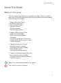
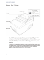
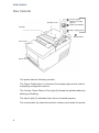
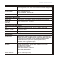
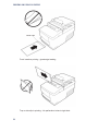
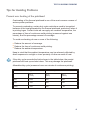
TH320
Thermal Printer
Users Guide
Edition May 2010
Microsoft and Windows NT are registered Trademarks of Microsoft Corporation in the
U.S.A. and/or other countries
BEETLE® is a registered trademark of the Wincor Nixdorf International GmbH, Germany
Copyright © Wincor Nixdorf International GmbH, 2010
The reproduction, transmission or use of this document or its contents is not permitted without express authority.
Offenders will be liable for damages. All rights, including rights created by patent
grant or registration of a utility model or design, are reserved.
Delivery subject to availability; technical modifications possible.
Contents
Manufacturer’s Declaration and Approval ........................1
General Authorization .................................................................................1
FCC-Class A Declaration............................................................................1
User Information .........................................................................................1
Safety Information.......................................................................................2
Instructions for Maintenance .......................................................................3
Warranty .....................................................................................................3
Recycling ....................................................................................................3
Voluntary Control Council for Interference (VCCI)
Radio Frequency Interference Statement ...................................................4
About This Guide.................................................................5
What is in this guide....................................................................................5
About the Printer .................................................................6
User Controls ..............................................................................................8
Audible Beeps .......................................................................................9
Available printer configurations ...................................................................9
Printer configuration identification .........................................................9
Communication interfaces.....................................................................9
Printer Specifications ................................................................................10
Setting up the Printer ........................................................12
Getting Started..........................................................................................12
Choose a location .....................................................................................12
Unpack the printer .............................................................................13
Keep the packaging.............................................................................13
Check the packing list .........................................................................14
Removal of internal restraint items ......................................................14
Installing new receipt paper ......................................................................15
Installing or replacing the ribbon cassette .................................................16
Replacing a used ribbon cassette .............................................................16
Installing a new ribbon cassette ................................................................17
Connect the cables ...................................................................................18
Cash drawer cables.............................................................................18
Communication cables ........................................................................19
If installing the USB communication cable ..........................................20
If installing the Powered USB cable ....................................................20
Power supply cable ...................................................................................21
Cable routing .......................................................................................22
Testing the printer .....................................................................................22
Test Procedure....................................................................................23
Test Printout ................................................................................24
Printer configurations ................................................................................25
Configuring the printer ..............................................................................26
Communication interface.....................................................................28
Diagnostic modes .....................................................................................30
Enable or disable data scope mode ....................................................30
Enable or disable receipt test mode ....................................................31
Enable or disable slip test mode..........................................................31
Enable or disable MICR test mode......................................................32
Setting the printer emulations and software options ............................33
Slip Options.........................................................................................33
Setting Up the Printer................................................................................34
Using the Printer................................................................36
Printing on forms or checks ......................................................................36
Front insertion method ........................................................................36
Dropin method.....................................................................................37
Proper insertion of multi-partforms ......................................................37
Verifying and validating checks (optional) .................................................39
Tips for Avoiding Problems .......................................................................41
Prevent over heating of the printhead .................................................41
Avoid Harsh Environments ..................................................................42
Troubleshooting ................................................................43
Status Indicators .......................................................................................43
Typical Remedy Procedure .................................................................43
Printer beeps.......................................................................................44
Printer will not print..............................................................................44
On-line, paper status, error light flashes..............................................45
Slip-inlight does not operate ................................................................46
Check print quality poor.......................................................................46
Receipt print quality poor.....................................................................47
Slip station and MICR problems ..........................................................48
The knife does not operate..................................................................49
Other conditions........................................................................................50
FEDERAL COMMUNICATIONS COMMISSION (FCC)
Manufacturer’s Declaration and Approval
General Authorization
The device complies with the requirements of the directive 2004/108/EC with regard to ‘Electromagnetic
compatibility" and 2006/95/EC “Low Voltage Directive”.
Therefore, you will find the CE mark on the device or
packaging.
FCC-Class A Declaration
This equipment has been tested and found to comply with the limits for a
Class A digital device, pursuant to part 15 of the FCC Rules. These limits
are designed to provide reasonable protection against harmful interference
when the equipment is operated in a commercial environment. This
equipment generates, uses, and can radiate radio frequency energy and, if
not installed and used in accordance with the instruction manual, may cause
harmful interference to radio communications.
Operation of this equipment in a residential area is likely to cause harmful
interference in which case the user will be required to correct the
interference at his own expense.
Modifications not authorized by the manufacturer may void users authority
to operate this device.
This class A digital apparatus complies with Canadian ICES-003. Cet
appareil numerique de la classe A est conforme à la norme NMB-003 du
Canada.
Additionally, the TH320 has received the cUL and UL
approval.
User Information
Wincor Nixdorf International GmbH does not accept responsibility for radio
and TV interference and faults that are caused by unauthorized changes
1
SAFETY INFORMATION
that have been made to the devices. Furthermore, cables or other devices
that have not been approved by Wincor Nixdorf may not be connected to
the device. The user is responsible for any faults and interference that are
caused as a result.
Repair work on the devices should only be carried out by authorized and
specially trained personnel. Improper repairs will lead to the loss of any
guarantee and liability claims.
Extension boards with electrostatically endangered components can be
identified with this label.
Safety Information
This device conforms to the corresponding safety regulations for information
technology devices, including electronic office machines for use in the office
environment. Connect only WN approved power supplies.
n
n
n
n
n
n
n
2
If the device is moved from a cold environment to a warmer room where it
is to be operated, condensation could occur. The device must be
completely dry before being put into operation. Therefore an
acclimatization time of at least two hours should be accounted for.
Lay all cables and supply lines so that nobody can tread on them or trip
over them.
Data cables should neither be connected nor removed during electrical
storms.
Protect the device from vibrations, dust, moisture and heat, and only
transport the device in its original packaging (to protect it against impact
and blows).
Take care to ensure that no foreign objects (e.g. paper clips) or
liquids can get into the inside of the device, as this could cause
electrical shocks or short circuits.
In case of emergencies (e.g. damaged housing, liquid or foreign objects
getting into the device), the device should be switched off immediately.
Generally you should connect IT-devices only to power supply systems
with separately guided protective earth conductor (PE), known as TN-S
networks. Do not use PEN conductors! Please also observe the
recommendations of the norm DIN VDE 0100, part 540, Appendix C2, as
well as EN50174-2, §5.4.3.
INSTRUCTIONS FOR MAINTENANCE
Instructions for Maintenance
Clean your TH320 regularly with an appropriate surface cleaning product.
Make sure that the device is switched off, connector cables are unplugged
and that no moisture is allowed to get into the inside of the device.
Please observe the maintenance and cleaning instructions for each of the
TH320 components. These instructions can be found in their respective
chapters.
Warranty
Wincor Nixdorf guarantees generally a warranty engagement for 12 months
beginning with the date of delivery. This warranty engagement covers all
those damages which occur despite a normal use of the product.
Damages because of
n improper or insufficient maintenance,
n improper use of the product or unauthorized modifications of the product,
n inadequate location or surroundings
will not be covered by the warranty.
For further information of the stipulation look at your contract.
All parts of the product which are subject to wear and tear are not included
in the warranty engagement.
Please order spare parts at the Wincor Nixdorf customer service.
Recycling
Environmental protection does not begin when the
time has come to dispose of the TH320; it begins with
the manufacturer. This product was designed according to our internal norm “Environmental conscious
product design and development”.
The TH320 is manufactured without the use of CFCs und CCHS and is
produced mainly from reusable components and materials. The processed
plastics can, for the most part, be recycled. Even the precious metals can
be recovered, thus saving energy und costly raw materials.
3
RECYCLING
Please do not stick labels onto plastic case parts. This would help us to
re-use components and material. You can protect our environment by only
switching on your equipment when it is actually needed. If possible, even
avoid the stand-by-mode as this wastes energy, too. Also switch your
equipment off when you take a longer break or finish your work.
Currently at present, there are still some parts that are not reusable.
Wincor Nixdorf guarantees the environmentally safe disposal of these parts
in a Recycling Center, which is certified pursuant to ISO 9001.
So don’t simply throw your TH320 on the scrap heap when it has served its
time, but take advantage of the environmentally smart up-to-date recycling
methods!
Please contact your competent branch for information on how to return and
re-use devices and disposible materials.
Voluntary Control Council for Interference (VCCI)
Radio Frequency Interference Statement
This is a Class B product based on the standard of the Voluntary Control
Council for Interference by Information Technology Equipment (VCCI). If
this equipment is used in a domestic environment, radio disturbance may
arise. When such trouble occurs, the user may be required to take
corrective actions.
4
ABOUT THE PRINTER
About This Guide
What is in this guide
The four chapters that follow are organized according to what you want to
learn about the printer, learn about the set up, operation, and routine testing
and servicing of the printer.
n
Chapter About the Printer
What the printer does
How it communicates
Operator controls
Standard features
General Specifications
n
Chapter Setting up the Printer
Preparing for installation
What comes with the printer
Packaging
Connecting the printer to the system
Configuring the printer for your needs
Testing the printer
n
Chapter Operating the Printer
Printing on forms or checks
Verifying and validating checks
Clearing paper jams
Tips for preventing problems
n
Chapter Troubleshooting and Service
Error signals visual and audible
Finding and solving printer problems
Technical support
Notes in the manual are marked by this symbol.
This symbol is used for warnings.
5
WHAT IS IN THIS GUIDE
About the Printer
Receipt Cover
Receipt
On-line, Paper
Status, Error light
(green)
Paper Feed Button
Slip in Light (green)
Front Cover
Slip of Check
The TH320 is a low-cost, high-efficiency, point-of-sale (POS) printer that
boasts the smallest footprint of any hybrid printer. It features fast
monochrome or two-color receipt printing plus a drop in validation print
station. The TH320 provides maximum flexibility, performance, and
reliability.
It consists of two specialized printers in one compact package: a two-color
thermal printer on top that prints receipts, and an impact slip printer to print
on forms and checks that you insert. Built-in MICR check reading or
validation is an optional feature of the TH320 printer.
6
WHAT IS IN THIS GUIDE
The TH320 fits easily in spaces where no other hybrid printer can and
connects to most host computers via the 25-pin RS-232 interface or USB or
PoweredUSB interface.
The printer’s standard command set allows it to work with software written
for Wincor Nixdorf or other compliant printers. A variety of sensors enables
the printer to communicate its status to the host computer. The printer also
has an electronic journal feature.
The easy-to-use thermal printer requires no ribbon or ink cartridge. Load
new paper by simply opening the receipt cover and dropping in a new roll.
The impact printer provides the power and flexibility to print on checks or
multi-part forms up to four plies, in a wide variety of sizes and orientations.
This section describes the printer’s features and options in more detail.
7
USER CONTROLS
User Controls
Receipt Cover
On-line, Paper
Status, Error light
(green)
Paper Feed Button
Receipt
Slip in Light (green)
Reset Button
Front Cover
Slip of Check
The printer has the following controls:
The Paper Feed button (1) advances the receipt paper and is used in
navigating configuration menus.
The On-line, Paper Status, Error light (2) shows the printer status by
shining or flashing.
The slip-in light (3) indicates that a form is inserted properly.
The reset button (4) clears the printer’s memory and resets the printer.
8
AVAILABLE PRINTER CONFIGURATIONS
Audible Beeps
After power is applied or after reset, the printer normally emits a single
beep. This indicates that the printer has successfully completed its
startup and self-test routine.
If, after startup or reset, the beeping continues in a single, double, or triple
pattern, an internal failure has occurred. Please call your service
representative.
Available printer configurations
There are several configurations of the printer, depending on the
combination of desired options.
Printer configuration identification
See the sample below to determine the printer configuration. The printer
configuration identification (model ID) is located on the model label attached
to the back of the printer. This information is also shown on the installation
quality report card. The model ID description is shown below.
Communication interfaces
n
n
n
RS-232C serial interface (25-pin)
Universal Serial Bus (USB)
Powered USB
9
PRINTER SPECIFICATIONS
Printer Specifications
Printer Output
Receipt Station
Slip Station
Print Method
Direct Thermal, 203 DPI
9-Pin Impact
Character Cell Size
13 X 24, 10 X 24
7 X 7, 12 X 7, 5 X 9
CPI
15.6 & 20.3
13.9 & 16.8
Print Columns
44 & 56
42 & 51
Print Line Width
72 mm (2.8 in.)
76.8 mm (3.02 in.)
Printing Speed
Monochrome 80 LPS
(250 mm/sec)*
Color 29.6 LPS (100 mm/sec)
4.8 LPS
Character Sets
Page 437, 737, 850, 852, 858 (with Eurosymbol), 860, 862, 863, 865, 866,
and 1252 (Expanded character sets available)
Bar Codes
UPC-A, UPC-E, Code 39, Code 93, Code 128, JAN8 and JAN13 (EAN),
Interleaved 2 of 5, Codabar, PDF 417 (receipt station only) GS1 DataBar
Auto Cutter
Partial Cut, leaves 5mm uncut on left edge
MICR Reader (option)
Character sets/fonts
E-13B and CMC-7, auto discriminate (Integrated in slip station)
Check Read Rate
99% minimum
Parsing Formats
E-13B only. Programmable to any format
Physical
Dimensions
(W x D x H)
165.10 mm x 289.56 mm x 167.64 mm (6.5 in. x 11.4 in. x 6.6 in.)
Weight
ca. 3.6 kg (approximately 8 pounds)
Power Requirements
24 VDC, 3 Amps
Software and Firmware Capability
Emulations Available
Application Compatible Escape Commands (ACEC) A756
Data Buffer
8K
* as of serial number K06440000, former values:180 mm/sec (59 LPS)
10
PRINTER SPECIFICATIONS
User Memory
2 to 12 MB: (optional)
shared for graphics, logos, user defined characters, user data storage, and
electronic jounal
Communication
Board Architecture supports:
25-pin RS232, USB, Powered USB
Printer Drivers
OLE POS for Windows XP and XP embedded, Java POS, USB
Thermal Paper Requirements
Paper Type
Direct Thermal, POS Grade(s), special requirements for color printing
Paper Roll
(W x Dia.)
80 mm x 83 mm (3.15 in. x 3.27 in.)
Impact Slip Forms Requirements
Size
69.85 mm x 127.00 mm (2.75 in. x 5.00 in.) minimum front & side
Maximum Length
279.4 mm (11.00 in.)
Number of Plies
1 - 4 ply multipart
Miscellaneous
Certifications
EMC emissions: EN55022:1998 Class B ITE emission requirements (EU);
FCC 47 CFR Part 15, Class B emissions requirements (USA), VCCI Class
B ITE emissions requirements (Japan); AS/NZS 3548:2002/CISPR22
Class B ITE emission requirements (Australia); EMC Immunity:
EN55024:1998/A1:2001
Information technology equipment (EU)
Reliability
Thermal Print Mechanism; 200 KM paper (59M lines) monochrome,
100 KM twocolor (53 M lines),
Auto Knife Cutter; 1.5M cuts
Impact Print Mechanism; 15 M lines
Impact Printhead; 200M characters,
MICR reader; 200,000 Reads
Paper Thickness
0.014 in. maximum (0.35 mm)
11
GETTING STARTED
Setting up the Printer
Getting Started
Before setting up the printer, be sure you read and understand each of the
sections in this chapter. The sections are presented in the sequence that
they should be performed.
16,76 cm (6,6 in.)
28,96 cm (11,4 in.)
16,5 cm (6,5 in.)
Choose a location
The TH320 printer being only 16,5 cm (6.5 inches) wide requires very little
counter space and may be set on or near the host computer. With the
RS-232C interface, you can place the printer up to 15 m (50 feet) (with the
USB interface up to 5 m (15 feet), PoweredUSB 3.8 m (12.5 feet) from the
BEETLE/host computer and power supply.
Do not place the printer in any dusty environment or anywhere that spillage
of drinks or other liquids can occur.
12
UNPACK THE PRINTER
Place the printer on a level surface, and make sure there is enough room to
open the receipt cover to change the paper and to open the front cover to
change the impact printer’s ribbon cassette.
Devices such as CRT monitors or large metal surfaces can affect the
printer’s magnetic field and cause intermittent check reading errors. Be sure
to locate the printer away from such sources of interference.
Be sure to leave adequate space at the rear of the printer for connecting
and accessing the cables.
If the printer has a built in Magnetic Ink Character Recognition (MICR)
check reader, you may need to make additional adjustments to the printer’s
location.
Unpack the printer
Keep the packaging
The packing materials protect the printer and help prevent damage. Be sure
to save all the packaging materials -including the cardboard supports in the
slip path.
13
UNPACK THE PRINTER
Remove and save the cardboard supports from the slip path after you have
placed the printer in its user position.
Check the packing list
Before installation, check that all the items on this list are included (printers
shipped in bulk may not include all these items):
n
n
n
n
n
n
Printer (enclosed in a plastic bag with corrugated pack)
Test printout protecting the printhead (inside receipt bucket)
Cardboard support for cantilever (on slip table)
Power supply with cable connecting to printer and power supply cord
connecting to power outlet (only if ordered with the printer)
Ribbon cassette
Setup Guide
Removal of internal restraint items
Internal packing restraints within the printer provide protection against
severe physical shock that occurs during shipment.
1. Remove these items only after placing the printer in its user position
2. Save all restraints and packaging materials for future use.
Having these packing materials on hand simplifies preparation of the printer
for shipping or for long-term storage.
14
INSTALLING NEW RECEIPT PAPER
Installing new receipt paper
If the online paper status error light blinks, Change the paper as soon
as convenient to avoid running out of paper part way through a
transaction.
If the On-line, Paper Status, Error light blinks fast, the paper is out. Change
the paper immediately or data may be lost. The printer can accept and store
only a limited amount of data without paper. Memory overload can occur in
the buffer, leading to a total loss of data.
If you are changing the type of paper (monochrome vs. two-color version or
manufacturer type) send the “Set paper type” (1D 81 m n) command
(description found in the "Programming Guide"). Refer to the “Set paper
type” selection in the configuration menu. See the section on
"Configuring the printer".
n
n
n
Open the receipt cover and remove the used roll and core (if present).
Tear off the end of the new roll so that the edge is loose.
Place the roll into the paper bucket with the paper unrolling from the
bottom of the roll, and with a few inches of paper extending over the
cabinet front.
Paper must unroll from the bottom of the roll to insure that the image
prints.
15
INSTALLING OR REPLACING THE RIBBON CASSETTE
n
n
n
Close the receipt cover while holding the paper over the front of the
cabinet.
Remove the excess paper by tearing it against the tear-off blade.
Press the paper feed button to advance the paper if necessary.
Installing or replacing the ribbon cassette
Change the impact printer’s ribbon cassette if it is printing lightly or
produces marks, lines or other inconsistent printing on the slip.
Use of other than an approved ribbon cassette can void all warranties and
cause damage from jamming and other ribbon problems.
Replacing a used ribbon cassette
Open the front cover (1) by grasping the cover on each side near the top
and swing toward you.
Pinch in tabs (2) of the old ribbon cassette and pull straight upward to
remove it.
Continue to “Installing a new ribbon cassette” step 2.
16
INSTALLING A NEW RIBBON CASSETTE
Installing a new ribbon cassette
Open the front cover (1) by grasping the cover on each side at the bottom
and swing up.
Unwrap the new ribbon cassette and tighten the ribbon by turning the knob
on the cassette in the direction of the arrow.
DO NOT remove the transparent mylar shield that protects the exposed
ribbon.
Position the ribbon cassette on the carriage, as shown (2), making sure the
ribbon is not caught on the printhead.
Snap the cassette into place (2) and close the cover.
17
CONNECT THE CABLES
Connect the cables
Cable connections are made at the back of the printer.
The cash drawer cable connects the printer to one or two cash drawers.
Be careful to connect the USB cable only to point A (below). Attempts to
connect the USB cable at point B can cause permanent damage to the
communications circuitry
Connector panel varies with printer configuration (25-pin serial and Powered
USB connector versions not shown.)
Cash drawer cables
The cash drawer cable connects the printer to one or two cash drawers.
Be careful to connect correct cable into printer only at the cash drawer
connector (B).
Plug the cable into the cash drawer connector (standard phone jack) located
at the rear of the printer.
If your system has two cash drawers, attach a Y-cable to the printer’s cash
drawer connector as shown.
18
CONNECT THE CABLES
Y-cable
Cash
drawer
Printer
Cash
drawer
Printer connector
(standard phone jack)
Communication cables
The communication cable connects the printer to the host computer.
25-pin RS-232C
communication connector
n
n
n
n
n
Power supply connector
Turn off the BEETLE/host computer.
Plug the communication cable into the connector at the bottom back of
the printer.
Secure the connector by tightening the screws.
Connect the cable to the BEETLE/host computer.
Turn host computer on.
19
CONNECT THE CABLES
If installing the USB communication cable
USB communication connector panel
Power supply connector
USB connector
Printer end of
USB cable
n
n
n
n
Computer end of
USB cable
Turn off the host computer.
Plug the printer end of the USB cable into the USB connector port on the
printer (A).
Route the cable from the printer as shown on the following page to
provide strain relief.
Plug the computer end of the USB cable into the computer. Make sure the
USB symbol on the connector is facing up when you plug it in.
After you have completed setting up the printer, you can install the USB
driver onto the host computer.
If installing the Powered USB cable
Powered USB connector
20
POWER SUPPLY CABLE
Printer end of
USB cable
n
n
n
n
n
n
n
Computer end of
USB cable
Be sure the host computer is powered off.
Plug the printer end of the USB cable into the USB connector port on the
printer.
Route the cable from the printer as shown on the following page to
provide strain relief.
Plug the computer end of the USB cable into the computer.
Plug the printer end of the Ethernet cable into the Ethernet connector port
on the printer (A). Make sure the connector snaps firmly in place.
Plug the computer end of the Ethernet cable into the Ethernet port of the
computer. Make sure the connector snaps firmly in place.
After you have connected the printer, you may need to set the printer
internal parameters for Ethernet operation. See “Ethernet terminology and
setup” section of the TH320 Programming Guide.
Power supply cable
To avoid damage to the printer, connect the power supply cable last.
25-pin RS-232C
communication connector
Power supply connector
Using this device without shielded cables voids the printer warranty, FCC
and CE Mark designation.
n
n
Plug the power cord into the back of the printer.
Route the cash drawer and power supply cables through the strain relief
as shown in the next page, when the printer is configured for USB and the
native “Cable routing”.
21
TESTING THE PRINTER
n
Plug the power cord into the power supply, then plug the power supply
into an outlet. The green light on the top cover will light up.
Cable routing
Prevent the printer from being accidentally unplugged by making sure the
cables are routed as shown in the illustration below.
Connector
Cover
(Closed)
Communication
Connector
(RS-232C)
(Route straight
out back of printer
and tighten
screws)
USB Cable
Strain Relief
Power
Supply
Cable
(Straight
back)
Power Supply
Strain Relief
USB
Cable
Cash Drawer Cable
USB Cable
Power Supply
Strain Relief
USB Cable
Strain Relief
Testing the printer
This test prints a complete list of printer settings (Diagnostic form) and
partially cuts the paper (see sample on next page). The test items listed
may vary depending on the printer model. This printout is useful to a service
representative when there is a problem. If the quality of the test printout is
poor (missing or faded text) see the Troubleshooting section in this
document.
Instructions at the end of the test printout describe how to enter the
configuration menu. The configuration menu allows you to change the
current settings of the printer.
22
TESTING THE PRINTER
Open receipt
cover
Push and hold
paper feed button while
closing receipt
cover
Test Procedure
n
n
n
n
To run the test, open the receipt cover (1); then, while holding down the
paper feed button, close the receipt cover (2).
When the printer begins printing let go of the paper feed button. The
diagnostic printout will print.
Review this printout for printer settings. If you wish to change any of these
settings go to the configuration menu as instructed at the bottom of the
printout.
Make selections as instructed on the printout.
Be extremely careful changing any of the printer settings to avoid
inadvertently changing other settings that might affect the performance of
the printer.
23
TESTING THE PRINTER
Test Printout
24
PRINTER CONFIGURATIONS
Paper type can be changed in the configuration menu. Paper types and
grades available:
Type 0 - Monochrome grades Kanzaki P-310
Type 1 - Two-color grades Kanzaki P-310 RB
Type 4 - Two-color grades Kanzaki P-320 BB
Type 5 - Two-color grades Kanzaki P-320 RB
See the Programming Guide for more information.
Printer configurations
Printers are shipped with all the functions and parameters pre-set at the
factory. Settings for various printer parameters can be changed. This menu
is printed on the receipt and scrolls through instructions for selecting and
changing user changeable functions or parameters.
Be extremely careful changing any of the printer settings to avoid
inadvertently changing other settings that might affect the performance of
the printer.
The following functions and parameters can be changed in the scrolling
configuration menu (*except as noted):
n
Communication Interface
RS-232C serial interface
Universal serial bus (USB)/Powered USB
n
RS-232C serial interface settings
Baud rate
Data bits (*fixed at 8)
Stop bits (*fixed at 1)
Parity
Flow control
Hardware (DTR/DSR) or
Software (XON/XOFF)
n
Data reception errors
Alternate DTR/DSR
n
Diagnostic Modes
Normal
Datascope
25
CONFIGURING THE PRINTER
Receipt test
Slip test
MICR test
Check flip test
n
Emulation/software options
Printer emulations
Printer ID
Receipt Options
Default lines per inch
Carriage return usage
Default font
Font size
Slip options
Hardware options sub-menu
Printhead setting
Paper type
Color density
Print density (mono)
Power supply wattage (max power)
Alternate reset feature
Paper low sensor
MICR
MICR dual pass option
Configuring the printer
Be extremely careful changing any of the printer settings to avoid
inadvertently changing other settings that might affect the performance of
the printer.
n
Open the receipt cover and check if there is paper in the printer. If not,
follow the instructions for loading paper.
n
Turn the printer so the back is facing you.
n
Set DIP switch 1 to the On position (down).
Open the receipt cover and press the reset button while holding the paper
feed button.
The printer beeps, prints the diagnostic form and the configuration main
menu.
26
CONFIGURING THE PRINTER
The printer pauses and waits for a main menu selection to be made (see
sample printout below.)
Switch 1 is shown
in the on position
Off
On
2-position DIP switches
back of printer
n
Follow the printed instructions on the scrolling menu by pressing the
paper feed button as indicated below to make selections.
Indicate Yes with a long click. (Press and hold paper feed button for more
than one second.)
Indicate No with a short click. (Press paper feed button quickly.).
n
Continue through your menu selections until you are asked, “Save New
Parameters?” Select “Yes” or “No”.
27
CONFIGURING THE PRINTER
If you wish to save, select “Yes”, then return DIP switch 1 to the
Off position (up).
Press the reset button. The printer resets with the new selections.
You can verify the setting by pressing the paper feed button to
print out a diagnostics form or by holding the paper feed button
and opening and closing the receipt cover.
n
If you would like to continue configuring the printer, select “No”. The
printer returns to the configuration menu where you can set parameters
again.
Communication interface
To change the communication interface settings, enter the configuration
menu, select “Set Communication Interface” from the main menu and
answer “Yes” to “SET INTERFACE TYPE?” printed on the receipt.
Be extremely careful changing any of the printer settings to avoid
inadvertently changing other settings that might affect the performance of
the printer.
28
CONFIGURING THE PRINTER
Press the paper feed button as instructed to select the communication
interface you want.
n
Communication interface
RS-232C interface
USB (USB or Powered USB)
RS-232C serial interface settings
To change the RS-232C serial interface settings, enter the configuration
menu, select “Set Communication Interface” from the main menu and
answer “No” to “SET INTERFACE TYPE?” printed on the receipt. This takes
you to the instructions for selecting the RS-232C settings.
Be extremely careful changing any of the printer settings to avoid
inadvertently changing other settings that might affect the performance of
the printer.
Press the paper feed button as instructed on the configuration menu to
select the RS-232C settings you want to change:
n
Baud rate
115200 baud
57600 baud
38400 baud
19200 baud
9600 baud
4800 baud
2400 baud
1200 baud
n
Number of data bits can not be changed
n
Stop bits can not be changed
n
Parity can not be changed
n
Hardware flow control
Software (XON/XOFF)
Hardware (DTR/DSR)
n
Data reception errors
Ignore errors
Print “?”
29
DIAGNOSTIC MODES
n
Alternate DTR/DSR
Enabled Disabled
Press the paper feed button for at least one second to validate the selection.
Diagnostic modes
To change the diagnostic modes enter the configuration menu, select “Set
Diagnostic Modes” from the main menu and select one of the following
modes:
n
n
n
n
n
Normal: normal operating mode of the printer.
Datascope: the receipt printer prints incoming commands and data in
hexadecimal format to help troubleshoot communication problems.
Receipt test: the receipt printer prints two code pages to verify proper
printing of the receipt.
Slip test: the slip printer prints two code pages to verify the slip printer is
operating properly.
MICR test mode: the receipt printer prints all characters recognized by the
MICR (check reader) to verify proper reading of an inserted check.
Enable or disable data scope mode
The data scope mode test prints a hexadecimal dump of all data sent to the
printer: “1” prints as hexadecimal 31, “A” prints as hexadecimal 41 and so
on. This helps troubleshoot communication problems and runs during a
normal application (after being enabled through printer configuration).
Data scope mode is usually considered a level 1 diagnostic test.
Data scope mode is enabled and disabled by selecting the “Diagnostic
Modes” sub-menu of the configuration menu.
Press the paper feed button as instructed on the “Diagnostic Modes Menu”
to enable or disable the data scope mode test.
n
n
Off, normal mode (Data scope mode disabled)
Data scope mode (enabled)
Press the paper feed button for at least one second to validate the selection.
30
DIAGNOSTIC MODES
To run the data scope mode
n After you have enabled the data scope mode, exit the configuration menu.
n Run a transaction from the BEETLE or host computer.
All commands and data sent from the BEETLE/host computer will be printed
as hexadecimal characters as shown in the illustration.
To exit the data scope mode
n Enter the configuration menu again.
See “Configuring the printer.”.
n Disable the data scope mode.
n Exit the configuration menu.
The printer is once again on-line and can communicate normally with the
host computer.
Enable or disable receipt test mode
The receipt test mode verifies proper receipt printing. Receipt test is
enabled and disabled by selecting the “Diagnostic Modes” sub-menu of the
configuration menu. See “Configuring the printer” for instructions on how to
enter the configuration menu.
To exit the receipt test mode
n Enter the configuration menu again. (See “Configuring the printer”)
n Disable the receipt test mode.
n Exit the configuration menu.
n The printer is on-line and can again communicate normally with the host
computer.
To run the Receipt test mode
n Enable the receipt test mode in the configuration menu.
n Exit the configuration menu.
n Push the paper feed button. The receipt station prints two code pages
and cuts the receipt.
n To repeat this test, push the paper feed button again.
Enable or disable slip test mode
The slip test mode verifies proper printing on a slip. Slip test is enabled or
disabled by selecting the “Diagnostic Modes” sub-menu of the configuration
menu. See “Configuring the printer” for instructions on how to enter the
configuration menu.
31
DIAGNOSTIC MODES
To run the slip test mode
n Enable the slip test mode in the configuration menu.
n Exit the configuration menu.
n Insert a slip into the slip station.
n Push the paper feed button. Two code pages will be printed.
n To repeat this test, preform steps 3 and 4 again.
To exit the slip test mode
n Enter the configuration menu again. (See “Configuring the printer”)
n Disable the slip test mode.
n Exit the configuration menu.
The printer is on-line and can again communicate normally with the host
computer.
Enable or disable MICR test mode
MICR test mode tests the MICR operation. In this mode the MICR reads the
characters on a check, but instead of transmitting the values to the software
it prints them out.
MICR test is enabled or disabled by selecting the “Diagnostic Modes”
sub-menu of the configuration menu. See “Configuring the printer” for
instructions on how to enter the configuration menu.
To run the MICR test mode
n Enable the MICR test mode through the configuration menu. Then exit the
configuration menu.
n Insert a check into the slip station. (See “Verifying and validating checks”)
n Once a check is detected by the printer, the platen closes and the
characters are read by the MICR check reader. The decoded data is
printed as characters on receipt paper. The platen is then opened, and
the test is re-started.
n The printed characters should match the characters on the check. If the
MICR check reader misreads a character, a question mark “?” is printed.
If no characters can be read, “NO MICR CHARACTERS” is printed.
To exit the MICR test mode
n Enter the configuration menu again.
n Disable the MICR test mode.
n Exit the configuration menu.
The printer returns to normal mode and can again communicate with the
host computer.
32
DIAGNOSTIC MODES
Setting the printer emulations and software options
Printer emulations determine what commands are available to the printer.
To change the printer emulations settings, select the “Emulations/Software
Options” sub-menu of the main menu and answer “Yes” to “Set the Printer
Emulations?” printed on the receipt. This takes you to the instructions for
setting the printer emulation.
Be extremely careful changing any of the printer settings to avoid
inadvertently changing other settings that might affect the performance of
the printer.
Press the paper feed button for at least one second to validate the selection.
n
Printer Emulation
Native mode
A756 Emulation
n
Printer ID mode
This function determines the ID value returned by the printer in response
to a Transmit printer ID command (1D 49 n). The printer can be
configured to send back the ID of the TH320, TH420, A758 or A756.
n
Carriage return usage
This function allows the printer to use the carriage return (hexadecimal
0D) command as a print command or to ignore it, depending on the
application.
Press the paper feed button as instructed to select the printer emulation you
want.
Slip Options
n
n
n
n
Slip eject at receipt select
When enabled the printer ejects the slip when receipt is selected.
Delete Lead Spaces: N Standard Columns
Sets the TH320 to delete number (N) of leading
spaces in the slip format for standard print.
Delete Lead Spaces: N Compressed Columns
Sets the TH320 to delete number (N) of leading
spaces in the slip format for compressed print.
Compressed Mode: Disabled/Enabled
Turns on compressed print for all slip printing
33
SETTING UP THE PRINTER
n
n
Delete Trailing Spaces: Disabled/Enabled
Removes all trailing spaces for slip printing.
Max Lines Rotated: N lines
Varies the spacing between the rotated print formats to allow
printing of more lines.
The setting (N) is changeable from 21 to 25 lines.
Setting Up the Printer
n
Printhead setting
This is the printhead energy rating. It must match the rating marked on
the front right of the thermal mechanism in the printer.
Do not change printhead setting unless printhead is replaced.
When a new thermal mechanism is installed, be sure this setting matches
the indicated energy rating on the mechanism.
n
Color density
Adjusts printhead energy level to change color printing or adjust to paper
variations. Factory setting is 100%.
Choose an energy level no higher than necessary to achieve a dark printout.
Failure to observe this rule may result in a printer service call or voiding the
printer warranty. Running at a higher energy level reduces the printhead life.
Consult your Wincor Nixdorf technical support specialist if you have any
questions.
n
Print density (monochrome papers only)
Adjusts printhead energy level to darken printout or adjust for paper variations. When the printer prints high-density color print lines (text or graphics), it automatically slows down. Factory setting is 100%.
Choose a print density setting no higher than necessary to achieve
acceptable print density.
Failure to observe this rule may result in a printer service call and may
void the printer warranty.
Running at a higher energy level reduces the printhead life. Consult your
Wincor Nixdorf technical support specialist if you have questions.
n
34
Power supply wattage (Max power)
SETTING UP THE PRINTER
You can choose between a 48-watt, 55-watt or 75-watt power supply. This
matches the wattage of the printer to the power supply.
48-watt power supply (for older BEETLE systems), 55-watt power supply
(standard), 75-watt power supply (Enables printer to optimize speed at
higher dot coverage.)
n
Alternate reset feature
This feature allows you to reset the TH320 by opening and closing the
front cover instead of using the dip switch or reset button.
n
Paper low sensor
Allows the user to enable or disable the paper low sensor.
n
MICR
Allows the user to enable or disable the MICR to read checks.
n
MICR dual pass option
This feature when enabled allows the printer to attempt a second reading
of the check MICR number, if the first attempt was unsuccessful.
35
PRINTING ON FORMS OR CHECKS
Using the Printer
Printing on forms or checks
Several types of transactions may require the insertion of a check or other
form into the printer:
n
n
n
n
n
n
Credit card transaction (requiring a merchant verification or authorization
slip)
Multiple-part forms such as credit transactions or merchandise returns
Electronic funds transfers
Electronic check
Check printing (printing the date, payee, and amount on the check face)
Check endorsement
The TH320 can also print on multi-part forms up to four parts thick. Use
either the front insertion or drop in method, described below.
Check
orientation
Front
cover
Front
cover
Slip
table
Slip
table
Front insertion method
n
n
n
36
Insert the form or check (as shown on the left above) from the front and
place it on the slip table with the print side up. If the form is extra long,
you may need to insert it from the side. A slight resistance may be felt
when the form comes in contact with the form stop.
Slide the form or check to the right until it aligns against the check guide.
Slide the form or check toward the top of the printer until the green slip-in
light on the top cover turns on. This indicates that both sensors are
covered.
PRINTING ON FORMS OR CHECKS
n
n
n
Follow the instructions from the host computer. The printer begins
printing.
Remove the form or check after it has been ejected.
Follow the instructions from the host computer to finish the transaction.
Dropin method
n
n
n
n
n
n
Insert the form or check (as shown on the right above) into the slot from
the top or side with the print side toward you. A slight resistance may be
felt when the form comes in contact with the form stop.
Move the form or check to the right until it is aligned against the right edge
of the slot.
Slide the form or check downward until the green slipin light on the top
cover turns on. This indicates that both sensors are covered.
Follow the instructions from the host computer. The printer begins
printing.
Remove the form or check after it has been fed back out.
Follow the instructions from the host computer to finish the transaction.
See the next page for proper insertion of multi-part forms.
Proper insertion of multi-partforms
Be sure to insert multi-part forms glued-edge-first as shown in the drawings
on this page, whether inserting the form from the front, top or side.
Failure to insert multi-forms properly can result in costly paper jams and
damage to the form.
37
PRINTING ON FORMS OR CHECKS
Glued edge
Front insertion printing - glued edge leading
Top or side slip-in printing - No perforation holes to right side
38
VERIFYING AND VALIDATING CHECKS (OPTIONAL)
Verifying and validating checks (optional)
The printer’s MICR check reader enables check verification and
validation by inserting the check from either the front or the top of the
printer.
To ensure that checks are properly verified and validated, they must be free
of folds and wrinkles and inserted correctly into the MICR printer. Smooth a
wrinkled or folded check for best performance.
Check orientation - face down
Do not fold check
Front
cover
Slip
table
To verify and validate a check inserted from the front:
n
n
Place the check face down on the slip table, with the bottom edge of the
check to the right. Move the check to the right so it aligns along the check
guide.
Slide the check straight forward into the printer until the green slip-in light
on the top right edge of the printer comes on, indicating both sensors are
covered.
39
VERIFYING AND VALIDATING CHECKS (OPTIONAL)
Hold the check to the right, against the check guide and release it as soon
as the printer begins to run.
n
Follow the instructions on the host computer to complete the MICR
process:
Upon instruction from the host, the check is fed into the printer, read and
backed out to a position ready for endorsement, if desired.
If the terminal indicates an incorrect read of the MICR:
Remove the check.
Reinsert the check, following steps 1, 2, and 3.
40
n
Remove the check only when it is fully released by the printer.
n
Continue to follow the instructions from the host computer to finish the
transaction.
TIPS FOR AVOIDING PROBLEMS
Tips for Avoiding Problems
Prevent over heating of the printhead
Overheating of the thermal printhead is one of the most common causes of
serious printer problems.
To prevent overheating, certain duty cycle restrictions need to be applied
because of the heat generated by the thermal printhead, particularly when it
is printing logos. Certain limits we can apply are: ambient temperature, the
percentage of time of continuous solid printing (measured against one
minute), and the percentage amount of coverage.
To avoid overheating do one or more of the following:
n
n
n
Reduce the amount of coverage.
Reduce the time of continuous solid printing.
Reduce the ambient temperature.
Keep in mind that the ambient temperature may be adversely affected by
direct exposure to sunlight or close proximity to other sources of heat.
If the duty cycle exceeds the limits shown in the table below, the receipt
printhead will heat up and shut down. This may damage the printhead.
Allowable duty cycle (measured over one minute of continuous printing)
Amount of solid coverage
Ambient temperature
25°C
(77°F)
35° C
(95°F)
50° C
(122°F)
20%
100%
50%
20%
40%
50%
25%
10%
100%
20%
10%
4%
41
TIPS FOR AVOIDING PROBLEMS
Duty cycle
Percentage of time that the specified “Amount of solid coverage” can be
printed during a one minute period of time.
Example:
at 20% solid coverage, 35° C temperature, a 50% duty cycle is to be used,
resulting in 30 seconds of printing and 30 seconds without printing.
For reference
A typical receipt with text (contains some blank spaces) is approximately
12% dot coverage.
A full line of text characters (every cell on the line has a character in it) is
approximately 25% dot coverage.
n
n
n
Graphics are approximately 40% dot coverage.
Barcodes are approximately 50% dot coverage.
A solid black line is 100% dot coverage.
Avoid Harsh Environments
The TH320 printer is a durable piece of equipment and can withstand a
range of physical environments. However, the printer’s internal mechanical
components are vulnerable to airborne contaminants, particularly in certain
harsh areas, such as home improvement stores, garden shops, and
warehouse environments. The printer can become inoperative rapidly in
these kinds of environments, if routine cleaning is not performed.
To prolong the serviceability of your printer in these harsh environments, we
recommend to upgrade with harsh environments kit and regular periodic
inspection and general cleaning of the MICR read head, sensors, carriage
shaft and both printer mechanisms.
42
STATUS INDICATORS
Troubleshooting
The simple design of TH320 requires virtually no periodic servicing.
However, if problems do occur, they can usually be diagnosed readily by
checking the light status indicators, below, then referring to appropriate
section of the Troubleshooting guide on the pages that follow.
Status Indicators
The on-line, paper status, error light is the light to the rear, on the top edge
of the printer. It may be the first indication that something is wrong.
The light closer to the front on the right edge of the printer indicates that a
form is inserted properly. It does not indicate an error.
For some unexpected conditions, the printer communicates the information
to the host computer and relies on the application to indicate what the
condition is.
The information on the following pages describes common conditions that
you could encounter and easily fix yourself. A few may require that you
contact a service representative.
You should be able to correct many of the conditions locally without calling
for service. However, if a condition persists, contact a service
representative. See “Contacting a service representative” at the end of this
chapter.
Typical Remedy Procedure
If an unexpected condition has occurred, take the following general steps:
n
n
n
n
Cycle the power of the printer and note its behavior.
Check the on-line, paper status, error light and compare its behavior to
the following table.
Test the receipt printer or slip printer by printing a sample test print as
described elsewhere in this document.
Determine if the condition is with the thermal receipt printer or the impact
slip printer and refer to the tables on the following pages.
43
STATUS INDICATORS
Light behavior
Printer status
Off
No power
Fast blink
Firmware download
Fast blink
Level 0 diagnostics
(occurs at power on and on reset)
Fast blink
Cover open (receipt or slip)
Paperout
Carriage jam
Slip jam
Knifejam
Slow blink
Paper low
Temperature error
Voltage error
Steady On
All other states
Printer beeps
Condition
Possible causes
What to do
Printer beeps in a single,
double, or triple pattern at first
power on.The on-line, paper
status, error light blinks in the
same pattern, and the printer
won’t power up.
The printer has a problem
with its electronics.
Contact a service
representative.
Printer beeps during normal
operation.
The printer may be
programmed to beep during
normal operation by the
software application used on
the host computer.
Consult your application
software manual.
Printer will not print
44
Condition
Possible causes
What to do
The on-line, paper status,
error light is blinking and the
printer won’t print.
The receipt paper may be
out, the cover open,the
knife jammed, the supply
voltage out of range, or the
print head temperature out
of range.
Check that the receipt paper
is properly loaded and covers
are closed. See the table at
the beginning of this section.
If problem continues contact
a service representative.
STATUS INDICATORS
Printer doesn’t have power
(light not on)
Power supply may be
defective.
If the power supply is plugged
in, but does not come on, you
need to order a new power
supply. See “Power supply
and power cords.”
Printer has power but
doesn’t print.
Cables may not be
connected properly.
Check all cable connections.
Check that the host computer
and power supply are both on
(the power supply is turned
on by plugging it into an
outlet). See “Connect the
cables.”
DIP switches not set
correctly.
Check the switch setting. DIP
switch one should be off (up)
for normal operation.
All other causes.
Contact a service
representative.
On-line, paper status, error light flashes
Condition
Possible causes
What to do
The on-line, paper
status, error light is
blinking and the
printer won’t print.
Receipt paper is out.
Change the paper now.
Do not run a transaction
without paper. Data may
be lost.
Receipt paper is out. Change the paper
immediately. See “Load and change the
receipt paper.”
Receipt or front cover is
open.
Close the cover. The printer can not
operate with any of the covers open.
The knife is jammed.
Open the receipt cover and check the
knife. Do not force the cover if it will not
open. Clear any jammed paper you can
see. Tear off any excess paper against
the tear-off blade.
The slip is jammed.
Open the front cover and clear paper
from path.
The carriage is jammed.
Open front cover and clear paper from
path.
Receipt paper is low.
There are about 4.5 meters, ± 3 meters,
(15 feet, ± 10 feet) of paper left. Change
the paper soon to avoid running out of
paper part way through a transaction.
See “Load and change the receipt
paper.”
45
STATUS INDICATORS
The on-line, paper
status, error light is
blinking and the
printer won’t print.
Thermal print head
temperature is out of
range.
The print head may overheat when
printing in a room where the temperature
is above the recommended operating
temperature or when printing high
density graphics continuously, regardless
of the room temperature. In either
case,the printer will shut off. If the
temperature of the print head is too hot,
adjust the room temperature or move the
printer to a cooler location. If the print
head is overheating because of printing
high density graphics continuously,
reduce the demand on the printer.
AC supply voltage is out
of range.
If paper is not low and no conditions
indicate that the thermal print head is too
hot, the power supply voltage is out of
range. Contact a service representative.
Slip-inlight does not operate
Condition
Possible causes
Light does not operate
No check or form inserted
into printer.
What to do
Check or form incorrectly
inserted.
Ensure the check or form
is aligned properly.
See “Printing on forms or
checks.”
Condition
Possible causes
What to do
Printer starts to print, but stops
while form is being printed.
Communication error or
software error.
Check the interface
cable. Check that the
software is working
properly.
Check print quality poor
46
STATUS INDICATORS
Forms print is light or spotty.
Form not inserted in
correctly.
See “Printing on forms or
checks.”
Impact print head is dirty or
defective.
Contact a service
representative.
Improper platen gap.
Contact a service
representative.
Ribbon cassette is defective
See “Installing or re
placing the ribbon
cassette.”
Ribbon cassette is worn.
Replace the ribbon cassette.
See “Installing or
replacing the ribbon
cassette.”
Light print, smudging, or slip
skews.
Platen gap needs
adjustment.
Contact a service
representative.
Receipt print quality poor
Condition
Possible causes
What to do
Colored stripe on
receipt.
Paper is low.
Change the paper.
Receipt does not come
out all the way.
Paper is jammed.
Open the receipt cover, inspect the
knife, and clear any jammed paper.
Printer starts to print,
but stops while the
receipt is being printed.
Paper is jammed.
Open the receipt cover, inspect the
knife, and clear any jammed paper.
47
STATUS INDICATORS
Print is light or spotty.
Paper roll loaded
incorrectly.
Check that the paper is loaded properly.
Thermal printhead is
dirty.
Use recommended thermal receipt
paper. Clean the thermal printhead with
an alcohol pen prior to going back to an
approved paper. Do not spray the
thermal printhead with household
cleaner as this may damage it and the
electronics. The thermal printhead does
not normally require cleaning if the
recommended paper grades are used.
If non-recommended paper has been
used for an extended period of time,
cleaning the printhead with an alcohol
pen will not help.
Printhead is
defective.
Contact a service representative.
Variations in paper.
Increase energy level of printhead in
“Color Density Adj” of the printer
configuration menu (see “Configuring
the printer” section).
Incorrect paper
setting
Check diagnostics setting.
Inconsistent printing, no
two-colorprint.
Paper type used and
papertype setting do
not match.
Print diagnostic formand verify paper
type setting to type 0, 1, 4, or 5 (see
“Configuring the printer”section)
Vertical column of print
is missing, one side of
receipt is missing, or top
or bottom half of
characters are missing.
Printhead is
defective.
Contact a service representative.
Incorrect printhead
setting
Check diagnostics setting
Color print is light.
Slip station and MICR problems
48
Condition
Possible causes
What to do
Slip-in light does not
come on.
Form or check not
inserted properly.
Line up the form or check against the
check guide (wall) and slide it toward
the front of the printer until it is visible
from the top (the light should come on).
Extra long forms may need to be
inserted from the side to disengage the
Form Stop. See “Printing on forms or
checks” section or “Verifying and
validating checks” section.
STATUS INDICATORS
Forms or checks skew
or catch in the slip
station.
There is an
obstruction or
paperjam in the slip
station.
Open the front cover and check for
paper jams or other obstruction in the
slip station. Clear the jammed paper or
obstruction.
The MICR check reader
does not read or
misreads checks.
The check is inserted
improperly.
Make sure the check is inserted
properly with the MICR characters
down. See “Verifying and validating
checks” section.
The check is
fraudulent.
Make sure that the check is not
fraudulent. On fraudulent checks, the
characters the printer reads may be
different from those that are visible on
the check face.
A nearby magnetic
source is interfering
with the check
reader.
Devices, such as CRT monitors,
security devices or large metal surfaces
near the printer can affect the printer’s
magnetic field, causing intermittent
errors when the MICR check reader is
operating. Move the printer away from
such items.
The knife does not operate
Condition
Possible causes
What to do
Receipt is not cut
Paper is jammed
Open the receipt cover, inspect the
knife, and clear any jammed paper.
All other problems.
Contact a service representative.
49
OTHER CONDITIONS
Other conditions
The following problems all need to be corrected by a qualified service
representative.
n
n
n
n
n
n
n
n
n
50
MICR check reader not operating properly
Forms not feeding into the slip/forms area properly
Missing dots in slip or forms printing
Printer will not cycle or stop when required
Illegible characters
Paper will not feed
Knife will not cycle or cut
Platen will not open or close
Printer will not communicate with the BEETLE/host computer
Herausgegeben von/Published by Wincor Nixdorf International GmbH
D-33094 Paderborn