1
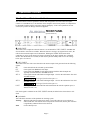
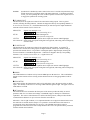
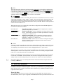
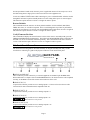
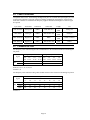
Mastering Analog to Digital and Digital to Analog Converter User Manual Lynx Studio Technology, Inc. www.lynxstudio.com [email protected] User Manual Table of Contents 1 Introduction .......................................................................................................... 1 1.1 1.2 1.3 1.4 1.5 1.6 1.7 Overview ...................................................................................................................... 1 Features ........................................................................................................................ 2 Nomenclature used in this manual ............................................................................... 2 In the Box ..................................................................................................................... 3 Power and Safety Information...................................................................................... 3 Rack-Mounting............................................................................................................. 3 Operation Requirements............................................................................................... 3 1.7.1 1.7.2 2 Operational Overview.......................................................................................... 5 2.1 2.2 2.3 2.4 2.5 2.6 Front Panel Controls and Indicators ............................................................................. 5 Multi-Key Commands.................................................................................................. 7 Back Panel Connections............................................................................................... 8 Cable Connections...................................................................................................... 10 Connector Pin Outs .................................................................................................... 10 Clock Settings and Connections................................................................................. 11 2.6.1 2.6.2 2.6.3 3 Aurora 16 as front end of digital mixer ...................................................................... 14 3.1.1 3.1.2 3.2 3.3 Clock settings ................................................................................................................ 19 Routing .......................................................................................................................... 19 Standalone Format Converter..................................................................................... 20 3.4.1 3.4.2 Clock settings ................................................................................................................ 20 Routing .......................................................................................................................... 20 Troubleshooting.................................................................................................. 21 EMC Certifications ............................................................................................ 23 5.1 5.2 5.3 FCC DECLARATION OF CONFORMITY.............................................................. 23 CE EMC DECLARATION OF CONFORMITY ...................................................... 23 CE SAFETY DECLARATION OF CONFORMITY ................................................ 24 Support................................................................................................................ 25 6.1 6.2 6.3 6.4 7 Clock settings ................................................................................................................ 17 Routing .......................................................................................................................... 17 Aurora 8 in Computer System with LynxTWO/L22.................................................. 18 3.3.1 3.3.2 3.4 Clock settings ................................................................................................................ 15 Routing .......................................................................................................................... 15 Aurora 16 in computer recording system with AES16............................................... 16 3.2.1 3.2.2 6 Aurora as Clock Master ................................................................................................. 11 Aurora as Clock Slave ................................................................................................... 12 SynchroLock.................................................................................................................. 13 Common Studio Setups...................................................................................... 14 3.1 4 5 Input/Output .................................................................................................................... 3 Remote Control................................................................................................................ 4 Lynx Website Support Resources .............................................................................. 25 Telephone Support ..................................................................................................... 25 Registering your Aurora............................................................................................. 25 Return Policy.............................................................................................................. 25 Warranty Information....................................................................................... 26 1 Introduction Thank you for choosing the Lynx Aurora 8™ / Aurora 16™ mastering AD/DA converter. The Aurora has been designed to provide you with the highest quality professional audio performance available, offering unequalled Analog-to-Digital and Digital-to-Analog conversion, flexible routing capabilities, I/O expansion options, external control functionality, and maximum channel capacity within a spaceefficient, single rack-space chassis. Please take a few moments to read through the entire user manual. Reading the manual prior to use will help to streamline the initial setup procedure and acquaint you with the Aurora’s superior feature set, allowing you to quickly realize the full potential of this powerful audio tool. Keep in mind that this manual covers the 16-channel Aurora 16, as well as the 8-channel Aurora 8. Both units are essentially feature identical with the exception of channel count. Descriptions and information that are pertinent only to the Aurora 8 will be marked the icon: Aurora 8 1.1 Overview The Lynx Aurora is a professional quality Analog to Digital and Digital to Analog converter using state-of-the-art components combined with a unique ability to adapt to today’s studio environment, as well as live and remote recording situations. Unlike most standalone pro audio converters, the Aurora provides 8 or 16 channels of AD and DA conversion with sample rates up to 192kHz. The Aurora provides the essential front-end for your digital audio workstation, digital mixer, or modular recording device. Through rigorous component selection, custom firmware programming, and input from a seasoned engineering team, the Aurora represents a level of sound quality previously available only to devices costing thousands of dollars more, suitable for mastering and acoustic measurement and analysis, as well as multi-channel music production. The Aurora features 24-bit AES3 digital I/O and supports sample rates up to 192kHz through Singlewire or Dual-wire operation. Several cable options are available that allow connection to a wide array of digital devices. Should one need support for other digital formats, the Aurora is easily expandable through the addition of convenient LStream™ or LSlot™ expansion cards. Currently, the LT-ADAT™ LStream card is available for ADAT Lightpipe Optical I/O and the LynxTWO/Aurora Interface Kit for integrating an Aurora with a LynxTWO or L22 card. Check the Lynx website for availability of LSlot expansion options. With exclusive SynchroLock™ technology, the Aurora provides unmatched tolerance to jitter when synchronizing to external clocks. This makes it an ideal solution for situations where noise sources are abundant, or where long cable runs are required. The SynchroLock output can also provide a clean and accurate clock for other connected audio devices. To adapt to the greatest variety of operational circumstances, several control options are available. Front panel controls offer access to the most frequently required parameters and allow for effective, independent operation. For use with a computer-based Digital Audio Workstation, the external remote control software allows users to access operational parameters, view real-time level meters for all inputs and outputs, save scenes, and route any input to any output from a convenient, easy to use interface. To use this software, the computer must either be equipped with the Lynx AES16™, a functional MIDI interface, or IrDA port. For live or remote recording situations, Lynx has developed a unique software interface allowing complete parameter control via infrared from a standard Pocket PC. Finally, the Aurora allows user-initiated firmware updates with files posted on the Lynx Studio Technology website. Firmware updates provide new features and compatibility and can improve the Page 1 operation of the unit. The Aurora firmware can be programmed via a connected Lynx audio interface, infrared or MIDI. 1.2 Features 16-channels of Analog-to-Digital and Digital-to-Analog conversion. Aurora 8 8 -channels Support for 44.1, 48, 88.2, 96, 176.4 and 192kHz sample rates. Sturdy, road-worthy, single rack-space chassis. 16-channels of AES/EBU digital I/O in Single-Wire mode, 8-channels in Dual-Wire mode. Aurora 8 8-channels in Single-Wire mode, 4-channels in Dual-Wire mode. Sync to external AES/EBU signals, word clock, or expansion devices. SynchroLock™ technology provides superior immunity to jitter in clock sources. 16-channels direct to PC or Mac computer system via Lynx AES16 PCI audio interface. Optional External LStream connection to LynxTWO/L22 sync port. Extensive front panel controls for standalone operation. Control of parameters, clock settings, mixing/routing, and mixer scenes with external control. External control is possible with a Lynx AES16, MIDI-equipped Mac or PC, or via Infrared. Windows CE software allows control of Aurora via an IrDA equipped Pocket PC. “Direct-connect” cabling available for digital mixers and recorders from Yamaha, Sony, Tascam, Mackie and other manufacturers. Precision LED level meters with analog or digital source selection. LSlot expansion port provides for addition of I/O options such as ADAT lightpipe, Firewire, etc. Firmware updates via Lynx AES16, infrared or MIDI. 1.3 Nomenclature used in this manual The following typographic conventions are used in this manual: ALL UPPER CASE TEXT refers to a specific parameter selection control (i.e. SYNC SOURCE) or a cable connection. Text in quotation marks indicates a parameter selection value or menu option (i.e. “EXT”). Phrases, such as: Start > Programs > Lynx Studio Technology use the greater than symbol (“>”) to indicate multiple menu options or mouse selections within a software control context. Page 2 1.4 In the Box The following items are included in your Aurora carton: Aurora Rack-Mount Converter AC Power Cord Aurora QuickStart Guide Aurora User’s Manual Warranty registration card If any items are missing or damaged, please contact your dealer or Lynx at http://www.lynxstudio.com. 1.5 Power and Safety Information To prevent fire or shock hazard, do not expose this equipment to rain or moisture. Do not block any of the ventilation openings. Do not defeat the safety purpose of the grounding-type plug. A grounding type plug has two blades and a third grounding prong. The third prong is provided for your safety. If the provided plug does not fit into your outlet, consult an electrician for replacement of the obsolete outlet. Protect the power cord from being walked on or pinched, particularly at the plugs, convenience receptacles, and the point where they connect to the Aurora. Unplug this device during lightning storms or when unused for long periods of time. Please note that the Aurora comes factory-configured for a specific voltage range, and cannot be changed in the field. The acceptable voltage range of the Aurora is printed on the label affixed to the top cover of the Aurora just above the AC power inlet. Failure to connect the Aurora to an AC power source that conforms to the requirements printed on the label may damage the Aurora and require it to be returned to the factory for non-warranty repair. 1.6 Rack-Mounting The Aurora is able be mounted in standard studio equipment racks. Please note that high performance, high resolution AD and DA converters generate substantial heat. For optimal performance and product longevity, it is necessary to leave an empty rack space above and below the Aurora. 1.7 Operation Requirements The Aurora was designed to operate seamlessly with industry-standard components. Control requirements pertain to use of external remote control software - disregard if you will be controlling the Aurora from its front panel controls only. 1.7.1 Input/Output The Aurora supports AES/EBU for the digital inputs and outputs, and can be used with any AES/EBU device that supports standard sample rates between 44.1kHz and 192 kHz in single-wire or dual-wire mode. Please refer to Section 2.4 Cable Connections for more information about available cable sets. The Aurora’s analog I/O can be used with balanced or unbalanced line level devices operating at a nominal trim level of +4dBu or –10dBV (switchable in banks of four channels). The analog outputs Page 3 are capable of delivering +20 dBu signal levels, it is important to verify that connected equipment is capable of handling these signal levels to prevent clipping or possible damage. 1.7.2 Remote Control In addition to front panel controls, the Aurora can be configured conveniently from the Aurora Remote Control software installed on a PC or Macintosh computer. A forthcoming Remote Control manual will detail the software installation and operation. To use the optional Remote Control software, one of the following conditions must be met: Via Lynx AES16 Audio Interface: A PC running Windows 2000/XP or a Macintosh running OSX with an installed and fully functional Rev B Lynx AES16 Audio Interface. The AES16 would connect to the Aurora via the Lynx CBL-AES1605 cable or equivalent. Via MIDI Interface: A PC running Windows 2000/XP or a Mac running OSX with an installed and fully functional MIDI interface. Attach a MIDI cable from the Aurora’s MIDI Out to the interface’s MIDI In, and the Aurora 16’s MIDI In to the interface’s MIDI Out. Via Infrared: A PC running Windows 2000/XP with an installed and fully functional IrDA infrared transceiver. Via Infrared with Pocket PC: A Pocket PC running Windows CE® Operating System with an IrDA transceiver. Page 4 2 Operational Overview 2.1 Front Panel Controls and Indicators The Aurora allows extensive parameter selection and configuration from convenient front panel controls. For standalone use, or in situations where computer control is not possible, it is important to be thoroughly familiar with the front panel controls and display. If the correct parameters are not selected, it is possible to damage connected equipment. FRONT PANEL (pictured Aurora 16) q SAMPLE RATE This button selects sample rate when the Aurora is set to Internal for SYNC SOURCE. Standard rates from 44.1kHz to 192 kHz are available. When the Aurora is slaving to an external clock source, the LED for the measured sample rate will illuminate. Holding the SAMPLE RATE button while connecting AC power to the Aurora will restore all settings to the factory default state. PLEASE NOTE: After the defaults are restored, the unit must be put into standby mode to save the settings before power is removed. w SYNC SOURCE This button selects the clock source that drives the Aurora sample clock generator from the following options: INT Clock derived from the on-board crystal oscillator. EXT Clock signal from WORD CLOCK input. EXT/2 Clock signal from WORD CLOCK input running at half the desired sample rate. Typically used with dual-wire AES/EBU devices. AES A Clock signal from the AES I/O Port A Digital Input. Clock is derived from the first valid AES/EBU channel. Aurora 8 Clock signal from the AES inputs 1-4 AES B Clock signal from the AES I/O Port B Digital Input. Clock is derived from the first valid AES/EBU channel. Aurora 8 Clock signal from the AES inputs 5-8 LSLOT Clock signal from an LSlot/LStream card installed into the LSLOT expansion port (i.e. ADAT, Firewire, etc.). If no clock signal is available for the SYNC SOURCE selected, the LED for the selected source will flash. e SynchroLock This LED shows the status of the SynchroLock clocking system. Flashing Working (analyzing incoming clock signal). It typically takes one to two minutes to achieve final lock. The Aurora can be used prior to a locked state, but the jitter reduction is significantly enhanced when lock is achieved. Solid Locked. Ready to use. Page 5 No LED SynchroLock is disabled by remote control or the source is outside of SynchroLock range and the Aurora has reverted back to the wide-range analog PLL. If SynchroLock failed to lock, you can tap through the SYNC SOURCE options to return to the original source to re-engage the SynchroLock clocking system. r TO ANALOG OUT This button selects the signal source that will be routed to the analog outputs. This is a global selection, affecting all analog channels. Channels are mapped to directly corresponding channels (i.e. In 1 to Out 1, In 2 to Out 2, etc.). Individual channels may be routed to specific output destinations when the external control is used. Choices are: ANALOG IN Signals from Analog In 1-16 Aurora 8 Signals from Analog In 1-8 AES IN Signals from Port A and Port B Digital In Aurora 8 Signals from Port A Digital In LSLOT IN Signals from LSLOT expansion device inputs (for instance ADAT lightpipe) All 3 LEDs ON In this mode, front panel routing has been bypassed, and routing will be managed by external control. t TO DIGITAL OUT This button selects the signal source that will be routed to the digital outputs. As with the TO ANALOG OUT selection, this setting impacts all digital channels, whereas per channel routing is possible with external control. It is possible to route digital inputs to digital outputs, allowing the Aurora to function as a standalone digital router. Channels are mapped to directly corresponding channels (i.e. In 1 to Out 1, In 2 to Out 2, etc.). Signal Choices are: ANALOG IN Signals from Analog In 1-16 Aurora 8 Signals from Analog In 1-8 AES IN Signals from Port A and Port B Digital In Aurora 8 Signals from Port A Digital In LSLOT IN Signals from LSLOT expansion device inputs (for instance ADAT lightpipe) All 3 LEDs ON In this mode, front panel routing has been bypassed, and routing will be managed by external control. y IR/MIDI This LED illuminates to indicate activity from the MIDI input or IR transceiver. This could indicate that the external control software is being used or that the firmware is being programmed via IR or MIDI. u PEAK METERS These meters display the instantaneous peak level of audio being sent to the Aurora analog or digital inputs. The intensity of the lower row of orange LEDs indicates signal strength. The upper row of red LEDs indicate overload. i IR Transceiver The infrared transceiver mounted on the front panel of the Aurora provides the ability to control parameters and view level meters and settings via handheld, laptop or desktop PC with Infrared capabilities. The Aurora’s infrared transceiver utilizes the IrDA protocol, which provides reliable communication at distances of up to one meter from the control device. Infrared is a “line of sight” medium, so it is important that there are no physical obstructions between the control device and the Aurora’s IR port. It is possible to use the IR features of the Aurora in environments where other infrared devices are in use. The intended control device must be programmed to control the Aurora with a unique hardware ID. This is an operation that is performed with the external control software. Page 6 o METER This button determines whether the peak meters display input activity for the digital or analog inputs. This button also determines the behavior of the TRIM/AES MODE controls. When the ANALOG LED is ON the meters indicate the levels for the analog inputs and outputs and the TRIM/AES MODE button controls the TRIM. When the DIGITAL LED is ON the meters indicate the levels for the digital inputs and outputs and the TRIM/AES MODE button controls the AES MODE. a TRIM/AES MODE When the meter select switch is set to analog, this button allows the nominal trim level to be set for the analog inputs and outputs to either +4dBu or -10dBV. When selected from the front panel button, this setting impacts all channels of input and output together, however analog inputs and outputs can be altered in groups of four channels when the Aurora is remotely controlled. Remote control operation is indicated when both LEDs are on. When the meter select is set to digital, this control allows configuration of the AES/EBU digital I/O. Four modes of operation are possible: Both LEDs OFF DUAL WIRE IN ON DUAL WIRE OUT ON Both LEDs ON Single Wire I/O Mode. Allows all channels of digital input or output to operate at sample rates up to 192kHz. Dual Wire Input Mode. Allows compatibility with legacy dual wire input devices. In this mode, the number of available input channels is reduced by ½ (Aurora 16 = 8, Aurora 8 = 4). Dual Wire Output Mode. Allows compatibility with legacy dual wire output devices. In this mode, the number of available output channels is reduced by ½ (Aurora 16 = 8, Aurora 8 = 4). Dual Wire I/O Mode. Enables dual wire mode for both inputs and outputs, allowing 8 channels maximum of digital I/O for the Aurora 16, and 4 channels for the Aurora 8. s POWER This button controls the standby state of the Aurora. When the front panel LEDs are not lit, the Aurora is in standby mode. In this state the Aurora is not functional and is using a minimal amount of power. To completely power down the Aurora, it must be unplugged from the AC power source. When the Aurora is in standby mode, pressing the POWER button will illuminate the front panel LEDs indicating that the Aurora is now ready for use. When the Aurora is in on mode, pressing the POWER button for ½ second will put the unit into standby mode. Holding the POWER button while connecting AC power to the Aurora will toggle the power-up mode to either ON or STANDBY. PLEASE NOTE: After the mode is changed the unit must be put into standby mode to save this setting before power is removed. See Section 2.2 for more information. PLEASE NOTE: It is best to wait until SynchroLock has achieved lock before using the Aurora for recording. See e above). 2.2 Multi-Key Commands In addition to the standard front panel controls detailed in 2.1, the Aurora has been programmed so that extended functionality is available through the use of multi-key combinations, or by pressing a button down while AC power is applied. The sections below detail these key combinations and the firmware required for each to operate. Power Up State This command changes the power up state of the Aurora from STANDBY (the default) to ON. In STANDBY mode, when AC power is applied, the POWER button must be pressed before the unit will Page 7 become operational. In ON mode, when AC power is applied the Aurora will be ready to use. ON is the ideal setting when a single power switch is used to turn on an equipment rack. To activate, hold the POWER button while connecting AC power. PLEASE NOTE: After the mode is changed the unit must be put into standby mode to save this setting before power is removed again. This function requires firmware revision 11 or higher in order to operate. Restore Defaults This command returns the Aurora to its factory default condition. SYNC SOURCE, ROUTING, TRIM, AES states, etc. will all be impacted. This is a useful diagnostic step whenever performance problems are encountered. To activate, press the SAMPLE RATE button while AC Power is applied. This function requires firmware revision 11 or higher in order to operate. Verify Firmware Revision This command will display the current firmware version of the Aurora. In standby mode, press the TRIM and POWER buttons simultaneously. The LEDs in the PEAK METER display will blink, and the LED over one or two channels will flash repeatedly. This is the number of the active firmware version. This function requires firmware revision 13 or higher in order to operate. 2.3 Back Panel Connections The Aurora has been designed for maximum flexibility to integrate smoothly into today’s studio environment. Following is a guide to the physical connectors on the Aurora back panel. BACK PANEL (pictured Aurora 16) d MIDI IN and MIDI OUT These connectors provide connectivity to external equipment via standard 5-pin din MIDI cables. When connected to a computer with an installed MIDI Interface, the Aurora firmware can be updated remotely, or the MIDI version of the remote control software can be used. f ANALOG IN (1-8) 25-pin D-Sub connector provides access to Analog Inputs 1-8. Please refer to Section 2.4 Cable Connections for more information about compatible cable sets. g ANALOG OUT (1-8) 25-pin D-Sub connector provides access to Analog Outputs 1-8 h ANALOG IN (9-16) 25-pin D-Sub connector provides access to Analog Inputs 9-16. Aurora 8 This connector is not present. j ANALOG OUT (9-16) 25-pin D-Sub connector provides access to Analog Outputs 9-16. Aurora 8 This connector is not present. Page 8 k AES I/O 1-8 (PORT A) 25-pin D-Sub connector provides access to AES/EBU Digital Inputs and Outputs 1-8. Please refer to Section 2.4 Cable Connections for more information about compatible cable sets. l LSLOT EXPANSION PORT Port for installation of LSlot or LStream expansion cards, used for expanding Aurora's interface options. Currently, the LT-ADAT expansion card is available to provide ADAT Lightpipe I/O. Other formats will be available soon. ; AES I/O 1-8 (PORT B) 25-pin D-Sub connector provides access to Digital Inputs and Outputs 9-16. Aurora 8 This connector is not present. 2) WORD CLOCK IN and WORD CLOCK OUT BNC connectors. WORD CLOCK IN WORD CLOCK OUT Allows Aurora to synchronize to an external clock source. With a valid clock source connected, choose “EXT” or “EXT/2” from SYNC SOURCE (use “EXT/2” when you wish to operate in dual-wire mode). For best results, wait until SynchroLock achieves full lock (when the SynchroLock LED turns solid) before converting audio. Allows external devices to synchronize to the Aurora sample clock generator. The Aurora will pass clock out this port when it is a clock master or clock slave. 2! AC POWER INLET For connection of AC power to the Aurora. Please note that the Aurora comes factory-configured for a specific voltage range, and cannot be changed in the field. The acceptable voltage range of the Aurora is printed on the label affixed to the top cover of the Aurora just above the AC power inlet. Failure to connect the Aurora to an AC power source that conforms to the requirements printed on the label may damage the Aurora and require it to be returned to the factory for non-warranty repair. Page 9 2.4 Cable Connections Compatible cables for the Aurora analog and digital I/O ports are available directly through Lynx. The 25-pin D-Sub connectors on Aurora conform to industry-standard pin configurations, so that off-theshelf cable solutions are available from third party suppliers should custom lengths or connector types be required. Lynx Cable Aurora Port Connectors Connectors CBL-AOUT85 Analog Out DB25 XLR Male X 8 CBL-AIN85 Analog In DB25 XLR Female X 8 CBL-AES1605 Digital I/O DB25 HD26 CBL-DIGY85 Digital I/O DB25 XLR Male X 4, XLR Female X 4 2.5 Length 16.4’ (5M) 16.4’ (5M) 16.4’ (5M) 16.4’ (5M) Use 8-Channels Balanced Analog Out 8-Channels Balanced Analog In 8-Channels AES/EBU In/Out to AES16 8-Channels AES/EBU In/Out Connector Pin Outs For third-party cable solutions Digital cables should adhere to the Yamaha MY8AE96 YGDAI Digital I/O pinout: Signal Pin Hot Cold Digital Input Channels 1-2 3-4 5-6 7-8 9-10 11-12 13-14 15-16 1 2 3 4 14 15 16 17 Digital Output Channels 1-2 3-4 5-6 7-8 9-10 11-12 13-14 15-16 5 6 7 8 18 19 20 21 GND: 10, 12, 13, 22, 23, 24, 25 Unused: 9, 11 For third-party cable solutions Analog cables should conform to the Tascam DA-88 Analog I/O pinout: Signal Pin Hot Cold GND 1 9 24 12 25 2 10 10 23 11 Analog Channels 3 4 5 6 11 12 13 14 21 7 18 4 9 20 6 17 22 8 19 5 Unused: 13 Page 10 7 15 15 3 16 8 16 1 14 2 2.6 Clock Settings and Connections In any system with more than one digital device, there can be only one master clock providing synchronization to all connected devices. Whether you designate the Aurora as the clock master, thereby slaving all other devices to the Aurora, or slave the Aurora to another clock master, it is important that only a single device act as clock master, to prevent the occurrence of audible digital errors. The Aurora provides several options for providing sample clock to other devices, or to receive clock from other devices. Only one clock source can be used at a time for both the analog and digital I/O. 2.6.1 Aurora as Clock Master To establish the Aurora as the sample clock master, choose “INT” with the SYNC SOURCE button on the front panel (see Section 2.1 Front Panel Controls and Indicators, item w). This will enable the Aurora to generate a sample clock from its internal low-jitter crystal oscillator. In this state, the analog-to-digital and digital-to-analog converters in the Aurora will derive clock from the internal clock generator, as will any external devices connected to the Aurora’s digital outputs or word clock output. When using the internal clock it is necessary to choose the appropriate sample rate using the SAMPLE RATE button on the front panel (see Section 2.1 Front Panel Controls and Indicators, item q). The Aurora supports sample rates of 44.1, 48, 88.2, 96, 176.4 and 192 kHz. External devices can slave to the Aurora clock via the DIGITAL outputs or WORD CLOCK output (see Section 2.4 Cable Connections) as well as digital I/O from an LSlot expansion card. The WORD CLOCK out provides a 75-ohm TTL level signal at a frequency that tracks the sample clock rate of the Aurora. Connect this output to the word clock input of an external device using a 75-ohm cable with BNC connectors. Consult the documentation for the slave device to determine how to set it to receive sample clock from its digital input or word clock input. Page 11 2.6.2 Aurora as Clock Slave The Aurora can synchronize to sample clock from a variety of external sources. In order to establish the Aurora as a clock slave, the correct clock source must be specified and the appropriate physical connection made. A two-stage phase-lock loop system is used to generate a high-frequency PLL clock while attenuating jitter in the selected sample clock source. Refer to Section 2.6.3 for a description of the operation of the PLL’s. To choose the desired clock source, depress the SYNC SOURCE button on the Aurora front panel (see Section 2.1 Front Panel Controls and Indicators, item w) until the LED for the correct choice illuminates. With a valid external clock source selected, the incoming clock will be measured by the Aurora, and the LED that corresponds to measured sample rate in the SAMPLE RATE portion of the front panel will illuminate (see Section 2.1 Front Panel Controls and Indicators, item q). In addition to “INT”, which is described in Section 2.6.1 Aurora as Clock Master, clock choices include: EXT - External Clock signals from WORD CLOCK connector (see Section 2.3 Back Panel Connections, item 2)). This input supports TTL signal levels and is terminated with 75 ohms of impedance. Connect this input to the word clock output of an external device using a 75ohm cable with BNC connectors. Please note that the Aurora does NOT support 256X word clock, also known as Super Clock. EXT/2 - External Divided by 2 Clock signals from the WORD CLOCK connector. In this mode, the word clock signal received will be reduced by half. As an example, a received clock rate of 96kHz will run at 48kHz. This mode is necessary to operate in dual-wire mode, where each physical input or output connection passes a single channel of AES/EBU signal running at half the system sample rate, thereby allowing high sample rate operation with legacy devices that do not support single-wire operation over 50kHz. For more information on dual-wire operation, see Section 2.1 Front Panel Controls and Indicators, item a AES A – Port A Digital Input Word Clock recovered from the Port A digital input. All four AES3 inputs on Port A are scanned, and clock is derived from the first valid AES/EBU channel. If there are no valid sources connected to Port A, Port B will be scanned for a valid clock source. If multiple digital devices are connected to this port, connect the device that you intend to be the clock source to Input 1. Aurora 8 Wordclock from AES inputs 1-4. AES B – Port B Digital Input Word Clock recovered from the Port B digital input, like above. If no valid sources are connected to Port B, Port A will be scanned for a valid clock source. Aurora 8 Wordclock from AES inputs 5-8. LSLOT Sample clock derived from cards installed in the LSlot expansion port. As an example, if the LT-ADAT is installed, and the intended clock source was a device connected to the one of the LT-ADAT’s optical inputs, LSLOT should be selected as the sync source. With LSlot expansion devices (like the LT-ADAT) that can receive clock from more than one port or channel, clock from the first valid port or channel will be used as the clock source. Whenever possible, connect the device intended to provide sample clock to the first available port and/or channel of the LSlot device. Page 12 2.6.3 SynchroLock The Aurora incorporates SynchroLock clock synchronization technology to provide extreme tolerance to noisy external AES/EBU and word clock signals while generating an ultra-low jitter clock. This technology is especially useful for combating noise induced on cables in complex studio installations. SynchroLock provides clock synchronization while insuring bit-perfect digital transmission. When the Aurora is connected in an AES/EBU daisy chain, SynchroLock acts like a jitter firewall to prevent the propagation of jitter to downstream devices. By coupling statistical analysis with low-noise clock generation techniques, SynchroLock is capable of attenuating jitter on incoming AES/EBU signals by a factor of 3000:1. Compare this to attenuation of 100:1 or less for professional quality analog phase-lock loops (PLL). SynchroLock can easily handle AES/EBU signals with jitter levels in excess of 800 nanoseconds. The SynchroLock sample clock is a two-stage system that is comprised of a fast-locking, wide-range analog PLL and digitally controlled crystal-based secondary stage. Due to extensive number crunching of the secondary stage, SynchroLock typically requires one to two minutes to achieve final lock. While the secondary stage is working, the analog PLL loop maintains lock, but with much less jitter attenuation than the secondary stage. When the final lock state is achieved, the secondary stage is switched on line and becomes the system clock source. In some cases this switching process may cause a momentary disruption in digital I/O. Because of this, it is recommended that recording or playback not be started until the SynchroLock LED is on solid (see Section 2.1 Front Panel Controls and Indicators, item e). SynchroLock works on any external word clock signal. By default, SynchroLock is active when the Sample Clock source is set to a clock source other than Internal. SynchroLock may only be disabled by external control of the Aurora. When disabled, the front panel SynchroLock LED will NOT be illuminated. SynchroLock is capable of locking to word clock frequencies within +/- 100ppm of 44.1 kHz, 48 kHz, 88.2kHz, 96 kHz, 176.4 kHz, or 192 kHz. Signals that fall outside of the lock range will cause the SynchroLock LED to flash. In this case, the analog PLL is active and will provide the system sample clock. To re-engage SynchroLock, simply tap through the SYNC SOURCE options to return to the original source. Page 13 3 Common Studio Setups The Aurora has been designed to operate effectively in a variety of audio production contexts. The purpose of this section is to illustrate some possible studio setups for these contexts. 3.1 Aurora 16 as front end of digital mixer The illustration below details the connection of the Aurora 16 to a digital mixer, providing 16 channels of AD and DA conversion. For this configuration to be valid, the mixer must provide two 8-channel AES/EBU ports with 25-pin D-Sub connectors that adhere to the Yamaha Digital pin configuration. Mixers using different pin configurations could be accommodated with cables other than those pictured. There are several options for establishing the clock relationship between the Aurora and the digital mixer. In this example, the Aurora is configured as the sample clock source, with the mixer slaving to the Aurora via the AES connection. Since there is no computer being used in this context, settings are implemented from the Aurora front panel or external remote control via IrDA. Aurora 8 This configuration is also valid for the Aurora 8, except that there would be 8channels of AD and DA conversion. Three cable sets would be used: one CBL-AIN85 for 8-channels of analog in, one CBL-AOUT85 for 8-channels of analog out, and one 25-pin D-Sub cable for 8channels of AES/EBU input and output. Page 14 3.1.1 Clock settings To use the Aurora as the clock master, select “INT” as the SYNC SOURCE from the Aurora front panel. Also, select the appropriate sample rate for your project. Make sure and only choose sample rates supported by your mixer. Change the clock source setting of the digital mixer to slave to one of its digital inputs. 3.1.2 Routing In this instance, signals from the analog inputs should be routed to the digital outputs for delivery to mixer channels. Similarly, the digital inputs providing signals from the mixer should be routed to the Aurora’s analog outputs, which will be connected to monitoring equipment. Page 15 3.2 Aurora 16 in computer recording system with AES16 This configuration facilitates 16 channels of Analog input and output to a computer installed with a Lynx AES16 AES/EBU Interface. The routing features of the Aurora 16 are augmented by the latency-free monitoring and routing features of the AES16, and external control is possible with the external remote control software. Communication between the AES16 and Aurora 16 occurs via two CBL-AES1605 cables, each of which transmits 8 channels of AES I/O. There are several possibilities for establishing a working clock scheme. For this example, we will have the AES16 be the clock master, and the Aurora 16 slave to the clock coming in to the Digital input. This arrangement allows great flexibility since the AES16 will respond automatically to sample rates requested from software, avoiding the need to manually establish sample rates that match the current project rate. Pictured are CBL-AIN85 and CBL-AOUT85 cables attached to the Analog Input and Output ports. These could be connected to any valid, line level signal source or monitoring destination. Aurora 8 This configuration is also valid for an Aurora 8, but with half the channel count. Page 16 3.2.1 Clock settings Clock settings should be established from the Lynx Mixer and the Aurora front panel. The Aurora should be SYNC SOURCE set to “AES A”. When a sample rate is chosen from the AES 16 Adapter page, or when playback or recording is initiated from a software application, the corresponding SAMPLE RATE LED on the Aurora front panel will illuminate. The AES16 should be set to “Internal” in the AES16 Adapter page. 3.2.2 Routing In this instance, signals from the Aurora’s analog inputs should be routed to the digital outputs for delivery to the AES16 inputs. Similarly, the digital inputs providing signals from the AES16 should be routed to the Aurora’s analog outputs, which will be connected to monitoring equipment. Select “AES IN” for TO ANALOG OUT and “ANALOG IN” for TO DIGITAL OUT from the Aurora front panel. Page 17 3.3 Aurora 8 in Computer System with LynxTWO/L22 This configuration augments the on-board connections of a LynxTWO or L22 card with 8-channels of Analog and AES/EBU I/O. This setup requires the LynxTWO/Aurora Interface Kit. LynxTWO/Aurora Interface Kit includes a 14-pin cable that connects to the SYNC PORT on the back of the LynxTWO/L22 and to an LStream Interface Bracket installed in the Aurora LSLOT port. This allows the Aurora to be addressed as an external LStream device. The Lynx Mixer can be used for routing, real-time meters and parameter selection on the Aurora. There are several unique advantages to this setup: Aurora I/O can be accessed easily using existing LynxTWO/L22 input and output driver devices You have access to both the Analog and AES I/O, since the Aurora to Computer connection is via LStream, rather than via AES. This is a great way to expand a LynxTWO card’s I/O without utilizing a PCI slot or running into the lack of multiple aggregate device support in some Operating Systems. Please note: when connected via external LStream, you can use up to 8–channels of I/O at sample rates up to 96kHz, and 4-channels at 176.4kHz or 192kHz. For this example we will configure the Aurora as the clock master, and have the LynxTWO/L22 slave. With this clock scheme, it would be necessary to set the Aurora to the appropriate sample rate for the audio being recorded or played. It is possible to use this configuration with an Aurora 16, with the following limitations: For 16-channels of I/O, you would be limited to a maximum sample rate of 48kHz, 8-channels at 88.2/96kHz, or 4-channels at 176.4/192kHz. Since the LynxTWO/L22 has a 16-channel structure, when using all 16-channels of Aurora I/O, the on-board I/O from your LynxTWO/L22 card would not be available. Page 18 3.3.1 Clock settings Since the Aurora will be the master clock, the SYNC SOURCE should be set to “INT”. The LynxTWO/ L22 should have the Preferred Clock Source set to “LStream 1” in the Lynx Mixer Adapter page. Select the appropriate sample rate for your project. Remember that through LStream you can get 8-channels at up to 96kHz, but a maximum of 4-channels at rates over 100kHz. 3.3.2 Routing In this instance, signals from the Aurora’s analog inputs should be routed to the digital outputs for delivery to the LynxTWO/L22 via LStream. By default the LSlot output mirrors the digital outputs. Similarly, the LSlot inputs provide signals from the LynxTWO/L22 via LStream, and should be routed to the Aurora’s analog outputs, which will be connected to monitoring equipment. Select “LSLOT” for TO ANALOG OUT and “ANALOG IN” for TO DIGITAL OUT from the Aurora front panel. Page 19 3.4 Standalone Format Converter In addition to AD and DA conversion, the Aurora is well suited to function as a digital format converter or digital patch bay. When used with the external control software, one has per-channel control of routing from any two inputs to any output. As a standalone device, routing is global for all channels. The example below details conversion from ADAT lightpipe by way of the LT-ADAT card installed into the Aurora 16’s expansion slot to AES/EBU for transfer to a hard disk recorder. For this example we’ll choose the ADAT device as the clock source. Aurora 8 This configuration is also valid for an Aurora 8, except there would be a total of 8channels of routing possible. In this case, only one In and Out Port from the LT-ADAT card would be utilized. 3.4.1 Clock settings To use the ADAT device as the clock master, select “LSLOT” as the SYNC SOURCE from the Aurora front panel. The sample rate being transmitted from the ADAT Lightpipe Device will illuminate on the Aurora’s SAMPLE RATE section. 3.4.2 Routing Signals from the Aurora LSlot input (ADAT lightpipe) should be routed to the AES output for delivery to the digital recorder. With external remote control software, change the LSlot source to Analog Out. Please see the external control manual for further information. Page 20 4 Troubleshooting Unit will not turn on: Check the following: • Is the AC Power Cord securely connected to the AC port on the Aurora, and is it securely connected to a valid, grounded AC Outlet? • Check the label by the AC adapter on the back of the Aurora to insure that you are using the correct version for your electrical system. The Aurora is available in 100V, 115V and 230V configurations. • Verify that you have pressed the Power Button on the Aurora. Clicking, popping or crackling noises in your audio: Check clock master settings. In any digital audio configuration, there can be one, and only one master clock, or else you will likely experience audible clock errors. All other digital audio devices must be configured as slaves to the designated master clock. Since the Aurora’s SynchroLock technology provides an extremely stable and jitter-resistant clock, we recommend setting the Aurora as the master clock in your digital audio system. If you choose to use another device as the sample clock master, make sure that the Aurora and any other connected devices are set to the appropriate clock source setting. Audio plays back at a faster or slower rate than expected: This is usually the result of mismatched clock rates and/or multiple clock masters. For example, if you are playing back audio recorded at 44.1 kHz, but you have set the clock for 48 kHz, the audio will play back faster and at a higher pitch than expected. Make certain you have set only one device as clock master, and that the selected sample rate matches the audio source. No audio to analog outputs: Check the following elements. • Insure that the Cable connected to the appropriate analog output port is the Lynx CBLAOUT85 or adheres to the Tascam DA-88 Analog I/O pin configuration. • Set the Meter Selection button to the appropriate signal source, and verify that there is meter activity on the inputs. Also make sure that the correct signal source is selected for TO ANALOG OUT from the Aurora front panel. • Verify that your monitoring equipment is turned on and the levels are turned up to a safe listening level. No audio to digital outputs: Check the following elements. • Insure that the Cable connected to the appropriate digital I/O port is the Lynx CBL-DIGY85 or adheres to the Yamaha MY8AE96 YGDAI Digital I/O pinout configuration. • Set the Meter Selection button to the appropriate signal source, and verify that there is meter activity on the inputs. Also make sure that the correct signal source is selected for TO DIGITAL OUT from the Aurora front panel. • Verify that your digital signal destination is configured to receive signals from its AES/EBU input, and that the levels are turned up to a safe listening level. Page 21 SynchroLock LED does not illuminate: This indicates that the SynchroLock clocking system cannot lock to the selected clock source. Check the following: • Make sure that the correct sample clock source has been selected from the SYNC SOURCE section of the front panel • Make sure that the clock source is turned on and has been set to operate from its internal clock. • Verify that the cables connecting the clock source to the Aurora are the correct type, are free from defects, and are securely connected. • See if SynchroLock has been disabled from the remote control software, if it is being used. After correcting the problem, page through Aurora’s sync sources until you return to the original selection. This will re-engage the SynchroLock clocking system. Output is too loud for my monitoring equipment: Is your monitoring destination a +4dBu or –10dBV line-level device? Most professional equipment uses +4dBu as the nominal level, and most consumer equipment uses –10dBV as the nominal level. From the Aurora front panel or external control software, you can establish the appropriate input and output trim levels for your equipment. At the –10dBV setting, output levels will decrease by 12.2dB. In addition, output levels for the Aurora can be managed from the remote control software. Since level attenuation with the Aurora’s internal mixer occurs in the digital domain, it is ideal to keep the output levels at maximum and adjust for a comfortable listening level from your monitoring destination (i.e. mixer, power amp, etc.) to preserve the optimum signal quality. The selected Sync Source is flashing, and the INT LED is illuminated: If a Sync Source is chosen where a valid clock signal is not detected, then the Aurora will revert to Internal until a valid signal is present for the chosen Sync Source. To correct: • • • Verify that the clock source is powered up. Verify that connecting cables are securely attached. Verify that the clock source has been set to operate off of its internal clock. The Sync Source LED is flashing alternately between INT and the selected Sync Source. This condition generally indicates that the device connected to the Sync Source selected has been set to slave to the Aurora. Since both devices are operating as a clock slave, the Aurora will search unsuccessfully for a signal to lock to. Correct by setting either the Aurora or the connected device to Internal. I’m only getting half as many channels of conversion as expected, and channels are not routed as I would expect. Check the status of the AES MODE parameter on the Aurora front panel (to view: press the METER button so DIGITAL is selected). If the connected device is operating in AES/EBU single-wire mode, the Aurora should also be set to single wire mode. Click the AES MODE selection button until the LEDs for DUAL WIRE IN and DUAL WIRE OUT are both off. Page 22 5 EMC Certifications 5.1 FCC DECLARATION OF CONFORMITY TRADE NAME: MODEL NUMBER: COMPLIANCE TEST REPORT NUMBER: COMPLIANCE TEST REPORT DATE: RESPONSIBLE PARTY (IN USA): ADDRESS: TELEPHONE: A/D and D/A Converter Aurora 8, Aurora 16 Covered by European Standards Report # B50929A1 October 14, 2005 Lynx Studio Technology, Inc. 711 West 17th Street, Suite H3, Costa Mesa, CA 92627 (949) 515-8265 This equipment has been tested and found to comply with the limits for a Class B digital device, pursuant to Part 15 of the FCC rules. These limits are designed to provide reasonable protection against harmful interference in a residential installation. This equipment generates, uses, and can radiate radio frequency energy and, if not installed and used in accordance with the instructions, may cause harmful interference to radio communications. However, there is no guarantee that interference will not occur in a particular installation. If the unit does cause harmful interference to radio or television reception, please refer to your user’s manual for instructions on correcting the problem. I the undersigned, hereby declare that the equipment specified above conforms to the above requirements. Costa Mesa, California October 14, 2005 Robert Bauman Compliance Engineer 5.2 CE EMC DECLARATION OF CONFORMITY MANUFACTURERS NAME: MANUFACTURER ADDRESS: COMPLIANCE TEST REPORT NUMBER: COMPLIANCE TEST REPORT DATE: TYPE OF EQUIPMENT: EQUIPMENT CLASS: MODEL NUMBER: CONFORMS TO THESE STANDARDS: YEAR OF MANUFACTURE: Lynx Studio Technology, Inc. 711 West 17th Street, Suite H3 Costa Mesa, CA 92627, U.S.A. B50929W1 October 14, 2005 Audio apparatus for professional use Residential, Commercial and Light Industry Aurora 8, Aurora 16 EN 55103-1, EN 55103-2 2005 I the undersigned, hereby declare that the equipment specified above conforms to the above directives and standards. Costa Mesa, California October 14, 2005 Robert Bauman Compliance Engineer Page 23 5.3 CE SAFETY DECLARATION OF CONFORMITY MANUFACTURERS NAME: MANUFACTURER ADDRESS: COMPLIANCE TEST REPORT NUMBER: COMPLIANCE TEST REPORT DATE: TYPE OF EQUIPMENT: EQUIPMENT CLASS: MODEL NUMBER: CONFORMS TO THESE STANDARDS: YEAR OF MANUFACTURE: Lynx Studio Technology, Inc. 711 West 17th Street, Suite H3 Costa Mesa, CA 92627, U.S.A. D50504S1 October 14, 2005 Audio apparatus for professional use Residential, Commercial and Light Industry Aurora 8, Aurora 16 EN 60065:2002 2005 I the undersigned, hereby declare that the equipment specified above conforms to the above directives and standards. Costa Mesa, California October 14, 2005 Robert Bauman Compliance Engineer Page 24 6 Support We are devoted to making your experience with the Aurora trouble-free and productive. If the troubleshooting and operational sections of this manual did not help resolve your questions, several support options are available to you: 6.1 Lynx Website Support Resources Logging on to http://www.lynxstudio.com/support.html will provide several options for resolving your support issues: Support Ticket For direct attention from the Lynx Technical Support Staff, registered users can submit a support ticket online that details their problem and steps they’ve taken to resolve it. Most Support Ticket submissions are responded to within 24 hours. Frequently Asked Questions An extensive catalog of FAQs derived directly from our most common tech support inquiries. Our FAQ section is updated regularly and designed to allow users to find the answers to their most common questions quickly. Firmware and Driver Downloads A library of current firmware and driver files are available for download and installation. Check back regularly to insure that your Aurora is up-to-date. Lynx Support Forum An online Lynx users support forum provides a venue for customers to post questions and issues and receive responses from other users as well as Lynx technical administrators. Searching previous posts is often an excellent way to uncover valuable information about Aurora operation and troubleshooting. See http://www.lynxstudio.com/forum 6.2 Telephone Support Telephone support is available by calling +1 (949) 515-8265 extension 206 from 9AM to 5PM Pacific Time, Monday through Friday, excluding United States Holidays. 6.3 Registering your Aurora Lynx is committed to providing you with the best service possible. To help us serve you better, please be sure to register your Aurora using one of the following methods: Fill out and mail the Warranty Registration Card included with your Aurora. Register on the web at: http://www.lynxstudio.com/support.html Once you are registered you will automatically receive notifications of new products and upgrades. 6.4 Return Policy If you have a unit that you suspect is defective or is malfunctioning contact Lynx technical support via one of the means described above for diagnosis. If the technician determines that the unit is faulty, they will issue an RMA number so you can send the unit in for repair. Units received without a valid RMA number will be refused. All RMA numbers are valid for 30 days from the date of issue. Page 25 7 Warranty Information One year Free Labor / One year Parts Exchange This product must be returned to the factory for repair. Who Is Covered? You must have proof of purchase to receive warranty service. A sales receipt or other document showing when and where you purchased the product is considered proof of purchase. This warranty is enforceable only by the original retail purchaser. To be protected by this warranty, the purchaser must complete and return the enclosed warranty card or register online within 14 days of purchase. What Is Covered? Warranty coverage beings the day you buy your product. For one year thereafter, Lynx shall, at its sole and absolute option, either repair or replace free of charge any product that proves to be defective on inspection by Lynx or its authorized service representative. In all cases disputes concerning this warranty shall be resolved as prescribed by law. All parts, including repaired and replaced parts, are covered only for the original warranty period. When the warranty on the product expires, the warranty on all replaced and repaired parts also expires. What Is Excluded? Your warranty does not cover: • Labor charges for installation or setup of the product. • Product repair and/or part replacement because of misuse, accident, unauthorized repair or other cause not within the control of Lynx. • A product that requires modification or adaptation to enable it to operate in any country other than the country for which it was designed, manufactured, approved and/or authorized, or repair of products damaged by these modifications. • Incidental or consequential damages result from the product, damage to property, damage based on inconvenience or on loss of use of the product, and, to the extent permitted by law, damages for personal injury. Some states do not allow the exclusion or limitation of incidental or consequential damages, so the above limitation or exclusion may not apply to you. • A product that is used for rental purposes. To Get Warranty Service… To obtain warranty service, the purchaser must first call or email Lynx at the email address or telephone number printed in Section 6 to obtain a Return Authorization Number and instructions concerning where to return the unit for service. All inquiries must be accompanied by a description of the problem. All authorized returns must be sent to Lynx or an authorized Lynx repair facility postage prepaid insured and properly packaged. Proof of purchase must be presented in the form of a bill of sale, canceled check or some other positive proof that the product is within the warranty period. Lynx reserves the right to update any unit returned for repair. Lynx reserves the right to change or improve design of the product at any time without prior notice. Lynx Studio Technology, Aurora and the Aurora Logo are trademarks of Lynx Studio Technology, Inc. All other product or company names are the trademarks or registered trademarks of their respective owners. Aurora™ User Manual Copyright © 1998-2007, Lynx Studio Technology, Inc. All rights reserved. Page 26 Aurora User Manual, June 16, 2007. Copyright © 1998-2007, Lynx Studio Technology, Inc. All rights reserved.