1
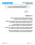
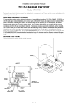
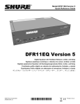
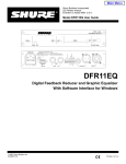
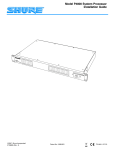
Shure Brothers Incorporated 222 Hartrey Avenue Evanston IL 60202-3696 U.S.A. Model UA888 User Guide NETWORKING INTERFACE SYSTEM UHF POWER LINK UA888 Networking System for UHF Wireless Microphones with Software Interface for Microsoft Windows Netzwerksystem für drahtlose UHF–Mikrofone mit Softwareschnittstelle für Microsoft Windows Système de gestion de réseau pour microphones sans fil UHF avec interface logicielle pour Microsoft Windows Sistema de conexión en red para micrófonos inalámbricos UHF con interfase de software para Microsoft Windows Sistema di collegamento in rete per radiomicrofoni UHF con interfaccia software per Microsoft Windows E1997, Shure Brothers Incorporated 27A8623 (QL) Printed in U.S.A. TABLE OF CONTENTS INTRODUCTION . . . . . . . . . . . . . . . . . . . . . . . . . . . . . . . . . . . . . . . . . . . . . . . . . . . . . . . . . . . . . . . . . . . . . . . . . . System Components . . . . . . . . . . . . . . . . . . . . . . . . . . . . . . . . . . . . . . . . . . . . . . . . . . . . . . . . . . . . . . . . . . . System Features . . . . . . . . . . . . . . . . . . . . . . . . . . . . . . . . . . . . . . . . . . . . . . . . . . . . . . . . . . . . . . . . . . . . . . Minimum Computer Requirements . . . . . . . . . . . . . . . . . . . . . . . . . . . . . . . . . . . . . . . . . . . . . . . . . . . . . . . UA888 Interface Module Connectors and Controls . . . . . . . . . . . . . . . . . . . . . . . . . . . . . . . . . . . . . . . . . 2 2 2 2 3 INSTALLATION . . . . . . . . . . . . . . . . . . . . . . . . . . . . . . . . . . . . . . . . . . . . . . . . . . . . . . . . . . . . . . . . . . . . . . . . . . . U4 Receiver Connection . . . . . . . . . . . . . . . . . . . . . . . . . . . . . . . . . . . . . . . . . . . . . . . . . . . . . . . . . . . . . . . . Computer Connection . . . . . . . . . . . . . . . . . . . . . . . . . . . . . . . . . . . . . . . . . . . . . . . . . . . . . . . . . . . . . . . . . . Installing UA888 Software . . . . . . . . . . . . . . . . . . . . . . . . . . . . . . . . . . . . . . . . . . . . . . . . . . . . . . . . . . . . . . Linking Multiple UA888 Interface Modules . . . . . . . . . . . . . . . . . . . . . . . . . . . . . . . . . . . . . . . . . . . . . . . . Connecting the UA888 System to a Sound System . . . . . . . . . . . . . . . . . . . . . . . . . . . . . . . . . . . . . . . . 4 4 4 5 5 6 USING THE UA888 SYSTEM . . . . . . . . . . . . . . . . . . . . . . . . . . . . . . . . . . . . . . . . . . . . . . . . . . . . . . . . . . . . . . . 7 Getting Started . . . . . . . . . . . . . . . . . . . . . . . . . . . . . . . . . . . . . . . . . . . . . . . . . . . . . . . . . . . . . . . . . . 7 Changing the COM Port Setting . . . . . . . . . . . . . . . . . . . . . . . . . . . . . . . . . . . . . . . . . . . . . . . . . . . 7 Connecting the Software . . . . . . . . . . . . . . . . . . . . . . . . . . . . . . . . . . . . . . . . . . . . . . . . . . . . . . . . . . 8 Disconnecting the Software . . . . . . . . . . . . . . . . . . . . . . . . . . . . . . . . . . . . . . . . . . . . . . . . . . . . . . . 8 Enlarging Receiver Display Icons . . . . . . . . . . . . . . . . . . . . . . . . . . . . . . . . . . . . . . . . . . . . . . . . . . 9 Detailed Receiver Display Elements . . . . . . . . . . . . . . . . . . . . . . . . . . . . . . . . . . . . . . . . . . . . . . . . 9 Changing the Receiver Settings . . . . . . . . . . . . . . . . . . . . . . . . . . . . . . . . . . . . . . . . . . . . . . . . . . 10 Changing Receiver Icon Colors . . . . . . . . . . . . . . . . . . . . . . . . . . . . . . . . . . . . . . . . . . . . . . . . . . . 10 Saving Scene Files . . . . . . . . . . . . . . . . . . . . . . . . . . . . . . . . . . . . . . . . . . . . . . . . . . . . . . . . . . . . . 11 Retrieving Scene Files . . . . . . . . . . . . . . . . . . . . . . . . . . . . . . . . . . . . . . . . . . . . . . . . . . . . . . . . . . 12 Deleting Scene Files . . . . . . . . . . . . . . . . . . . . . . . . . . . . . . . . . . . . . . . . . . . . . . . . . . . . . . . . . . . . 13 Using the “Walk Around” Plotter . . . . . . . . . . . . . . . . . . . . . . . . . . . . . . . . . . . . . . . . . . . . . . . . . . 13 Scanning for UHF Frequencies . . . . . . . . . . . . . . . . . . . . . . . . . . . . . . . . . . . . . . . . . . . . . . . . . . . 14 Installing Password Protection . . . . . . . . . . . . . . . . . . . . . . . . . . . . . . . . . . . . . . . . . . . . . . . . . . . . 16 Changing the Password . . . . . . . . . . . . . . . . . . . . . . . . . . . . . . . . . . . . . . . . . . . . . . . . . . . . . . . . . 16 Removing Password Protection . . . . . . . . . . . . . . . . . . . . . . . . . . . . . . . . . . . . . . . . . . . . . . . . . . . 17 Printing a Display . . . . . . . . . . . . . . . . . . . . . . . . . . . . . . . . . . . . . . . . . . . . . . . . . . . . . . . . . . . . . . . 17 Exiting the Program . . . . . . . . . . . . . . . . . . . . . . . . . . . . . . . . . . . . . . . . . . . . . . . . . . . . . . . . . . . . . 17 TROUBLESHOOTING . . . . . . . . . . . . . . . . . . . . . . . . . . . . . . . . . . . . . . . . . . . . . . . . . . . . . . . . . . . . . . . . . . . . 18 Answers to Commonly Asked Questions . . . . . . . . . . . . . . . . . . . . . . . . . . . . . . . . . . . . . . . . . . . 18 SPECIFICATIONS . . . . . . . . . . . . . . . . . . . . . . . . . . . . . . . . . . . . . . . . . . . . . . . . . . . . . . . . . . . . . . . . . . . . . . . . 19 APPENDIX A. RACK MOUNTING THE UA888 . . . . . . . . . . . . . . . . . . . . . . . . . . . . . . . . . . . . . . . . . . . . . . 20 APPENDIX B. CABLE CONNECTOR PIN MAPS . . . . . . . . . . . . . . . . . . . . . . . . . . . . . . . . . . . . . . . . . . . . 22 Trademark Notification: Shure is a registered trademark of Shure Brothers Incorporated. Shure Linkt is a trademark of Shure Brothers Incorporated. IBM is a registered trademark of International Business Machines Corporation. Microsoft and PowerPoint are registered trademarks of Microsoft Corporation. PC Paintbrush is a registered trademark of ZSoft Corporation. Visio is a registered trademark of Visio Corporation. PageMaker is a registered trademark of Adobe Systems Incorporated. Corel Draw! is a registered trademark of Corel Corporation. ENGLISH –1– INTRODUCTION The Shure UA888 Networking Interface System lets you use a computer to monitor and control up to 32 Shure UHF Wireless receivers from a remote site. The UA888 system is designed for installed sound reinforcement applications, including theater, larger houses of worship; touring sound systems; and audio/video rental applications. System Components The UA888 Networking Interface System is comprised of a rack-mountable Interface Module, Windows based software, connecting cables, an IBM compatible PC (not supplied) and Shure U4S or U4D diversity UHF receivers. The Shure U4 receivers are supplied separately. System Features S Monitor and control* of up to 32 receivers (64 channels maximum when using U4D dual receivers). Up to 32 channels can be viewed at one time. S Squelch monitor and control functions S Receiver lock/unlock function S Password protection S “Walk around” plotter function that measures rf signal strength and identifies ”dead” spots in the performing area S Frequency scanner function that identifies local rf activity controlled computer display S rf level monitor function S Diversity signal monitor function S Audio level monitor S Transmitter battery level monitor function S Name and label monitor and control S RS–232 serial interface S Frequency monitor and control functions S S Frequency group/channel monitor and control functions (TV channels in U.S. models) Shure Linkt interface to any Shure DSP devices, such as the DFR11EQ S Scene creation and storage capability NOTE: Version 1.5x and earlier U4 receivers will not support all of the above features without an upgrade. Refer to the Upgrade Kit notification sheet included with the unit or call Shure Brothers Incorporated at 1-800-516-2525. Minimum Computer Requirements S 486DX2, 66 MHz, IBM compatible computer; (Pentium 133 or greater recommended) S One available RS–232 serial COM port S 2.0 MB hard–drive space S 16 MB RAM S Windows version 3.1x or later S One RS–232 cable *NOTE: The “Monitor” feature lets you view various wireless system parameters and observe rf and audio performance, in real time, on the computer monitor. The “Control” feature lets you actually change receiver parameters from your computer terminal. –2– ENGLISH UA888 Interface Module Connectors and Controls Front Panel The front panel of the UA888 Interface Module, shown in Figure 1, includes the following controls and indicators: UHF NETWORKING INTERFACE SYSTEM POWER 1 2 UA888 INTERFACE MODULE FONT PANEL FIGURE 1 1. Power On LED. This LED glows green when the UA888 Interface Module is turned on. 2. Power ON/OFF Switch. Turns the UA888 Interface Module on and off. Rear Panel The rear panel of the UA888 Interface Module, shown in Figure 2, includes the following controls and indicators: LINK 1 2 3 4 UA888 INTERFACE MODULE REAR PANEL FIGURE 2 1. 25-Pin Connectors. Provide connection for up to eight Shure U4S (single) or U4D (dual) UHF receivers. 2. Shure Link Device Identification DIP Switches. These DIP switches are used to set the Link Device I.D. Number. When multiple UA888 Interface Modules are linked, each one is assigned a Link Device Identification Number (0, 1, 2, or 3). Each UA888 Interface Module comes with a factory preset Device I.D. of 0 (both switches in the down position). 3. 9-Pin RS-232 Port. Connects the UA888 Interface Module to an IBM–compatible PC. 4. Shure Link Interface. Allows up to four UA888 Interface Modules to be linked together. ENGLISH –3– INSTALLATION U4 Receiver Connection NOTE: At least one Shure U4S or U4D UHF receiver is required to install the UA888 system. 1. Install the UA888 in a 19-inch audio equipment rack. Refer to Appendix A. 2. Using the supplied 1 meter (3 ft.) cable, connect the 25-pin D connector labeled “Receiver A” on the rear panel of the UA888 to the 25-pin D connector on the rear panel of a U4 receiver. See Figure 3. 3. Plug in all connectors in the same manner until all receivers are connected to the UA888 Interface Module. TYPICAL UA888 CONNECTION TO A U4 RECEIVER FIGURE 3 Computer Connection 1. Determine whether the RS-232 serial port on the computer is a 9-pin or 25-pin connector. Refer to Appendix B for RS-232 cable diagrams. 2. Connect the 9–pin RS–232 port on the UA888 interface module to the RS–232 port on the computer, using the appropriate cable (not included with the system as purchased). CAUTION: To avoid damage to your computer, turn it off before connecting it to the UA888. See Figure 4. NOTE: The UA888 does not require a separate ac power cord. Power is derived from the U4 receiver. TO COMPUTER RS-232 CONNECTOR TYPICAL UA888 CONNECTIONS TO U4 RECEIVER AND A COMPUTER FIGURE 4 –4– ENGLISH Installing UA888 Software To install the UA888 software on your computer, proceed as follows: 1. Turn the computer and the UA888 Interface Module on. CAUTION: Leave the UA888 Interface Module turned on while it is physically connected to the receivers. Turning it off while the receivers are connected can affect receiver metering. However, it will not affect receiver performance. 2. Insert the supplied 3.5 inch diskette into the floppy drive on the computer. 3. If you are using Windows 3.11, click on the “File” heading on the main menu, then click on “Run.” If you are using Windows 95 or Windows NT, click on the “Start” button at the bottom of the window and select “Run.” 4. In the “Run” window, type “a:\setup” where “a” is the drive containing the UA888 diskette. The software will check the computer hardware to ensure that a coprocessor is present and suggest a destination for the UA888 files on the hard disk. It will also prompt you to type in your name and organizational information. NOTE: Please register your software by completing and mailing the enclosed registration card. You may also register on line via the Shure web site at http://www.shure.com. Linking Multiple UA888 Interface Modules A maximum of 32 Shure UHF receivers (up to 64 channels) can be monitored and controlled from a single computer by linking multiple UA888 Interface Modules and their associated receivers as follows: NOTE: Legal and practical rf considerations may limit the actual number of channels used to less than 64. 1. Assign each Interface Module a Device Identification Number (0–3) by sliding the DIP switches on the rear panel up or down, as shown in Figure 5. DEVICE ID # 0 DEVICE ID # 1 DEVICE ID # 2 (UP) (UP) (DOWN) (DOWN) 1 2 DEVICE ID # 3 (DOWN) (DOWN) 1 1 2 (UP) (UP) 2 1 2 UA888 DIP SWITCH SETTINGS FIGURE 5 NOTE: The UA888 must be turned off, then turned back on, for the DIP switch settings to take effect. 2. Using the supplied 5-pin DIN cable, connect the Shure Link OUT port of the first UA888 (the one connected directly to the computer) to the Shure Link IN port of the second UA888. See Figure 6. 3. Connect the Shure Link OUT port of the second UA888 to the Shure Link IN port of the third UA888. 4. Connect the Shure Link OUT on the last UA888 to the Shure Link IN on the first UA888. This creates a communication loop between all networked UA888 Interface Modules and the computer. NOTE: Although standard MIDI cable can be used, Shure Link is not MIDI compatible. TO COMPUTER RS-232 CONNECTOR TYPICAL CONFIGURATION OF MULTIPLE UA888 INTERFACE MODULES FIGURE 6 ENGLISH –5– Connecting the UA888 System to a Sound System The UA888 Networking System can be integrated into an existing Shure UHF wireless microphone system without changing the original equipment configuration. Simply connect the 25-pin D Network Interface connector on the rear panel of each U4 Receiver to one of the 25-pin D connectors on the rear panel of the UA888 Interface Module, using the supplied cable. A typical sound system incorporating the UA888 Networking System is shown in Figure 7. NOTE: If the connection between the UA888 Interface Module and the computer or a receiver is broken, the computer will display an error message. If this happens, check all connections and restart the UA888 program. TO RECEIVER 1 TO RECEIVER 2 TO RECEIVER 3 RS-232 LINE OUT UA888 INTERFACE MODULE ANTENNA B IN LINE IN TO RECEIVER 4 ANTENNA A IN IBM PC ANT A IN ANT A IN RECEIVER 1 ANT A IN AC POWER AUDIO OUT SHURE DFR11EQ #1 RECEIVER 2 RECEIVER 3 TRANSMITTER 3 AUDIO OUT CHANNEL B OUT CHANNEL A IN AUDIO OUT CHANNEL A OUT TRANSMITTER 2 SHURE DFR11EQ #2 SHURE LINK CABLE CHANNEL B IN ANT B IN ANT B IN ANT B IN TRANSMITTER 1 ANT B IN AC POWER ANT A IN UA840A ANTENNA DISTRIBUTION SYSTEM (OPTIONAL) AC POWER RECEIVER 4 POWER AMPLIFIER TRANSMITTER 4 AUDIO OUT DC POWER IN LOUDSPEAKERS MIXER DC POWER SUPPLY AC POWER MIXER TYPICAL SOUND SYSTEM WITH UA888 NETWORKING SYSTEM INSTALLED FIGURE 7 –6– ENGLISH USING THE UA888 SYSTEM Getting Started To activate the UA888 system, proceed as follows: 1. Turn on the computer, the UA888 Interface Module, and the U4 Receivers. 2. Go to the main menu on the computer display and double click on the UA888 icon, shown in Figure 8. If the system is linked to the computer via COM Port 1, it will automatically establish a software connection and detect any connected receivers. Icons of the receiver displays will appear on the right side of the main monitor window, as shown in Figure 9. UA888 PROGRAM ICON FIGURE 8 MAIN UA888 MONITOR DISPLAY FIGURE 9 Changing the COM Port Setting If COM Port 1 is not available, you must select another communications port before a successful software connection can be made. To change the COM port setting, proceed as follows: 1. Click on the “Setup” heading and select “COM port” from the pull down menu, as shown in Figure 10. SELECTING COM PORT FROM THE SETUP MENU FIGURE 10 ENGLISH –7– 2. When the window shown in Figure 11 appears, click on the COM port you wish to use. The default setting is COM 1. COM PORT SELECTION WINDOW FIGURE 11 3. Click on the “OK” button to activate your selection or click on “Cancel” and make a new selection. Connecting the Software To connect the program for any reason after it has been opened, proceed as follows: 1. Click on the “Setup” heading on the main menu bar and hold down the mouse button. 2. Select “Connect” from the pull down menu, as shown in Figure 12, and release the mouse button. ACTIVATING THE SOFTWARE CONNECT FUNCTION FIGURE 12 Disconnecting the Software To disconnect the software for any reason (before changing the COM port setting, for example), proceed as follows: 1. Click on the “Setup” heading on the main menu bar and hold down the mouse button. 2. Select “Disconnect” from the pull down menu, as shown in Figure 13, and release the mouse button. DEACTIVATING THE SOFTWARE CONNECT FUNCTION FIGURE 13 –8– ENGLISH Enlarging Receiver Display Icons To enlarge the receiver icons to show greater detail, proceed as follows: 1. Click on one of the receiver display icons and hold the mouse button down. 2. Drag the display to a square on the left side of the display and release the mouse button. Repeat this procedure for each receiver display you wish to enlarge. Refer to Figure 14. As you move each icon, a box will appear with that receiver’s I.D. number, UA888 port designation, and channel number. 1 2 3 4 4 5 2 6 7 8 9 10 11 ENLARGED RECEIVER DISPLAY ICONS FIGURE 14 Detailed Receiver Display Elements The enlarged receiver display icons include the following elements: 1. Menu Bar: Provides access to all system functions. 2. Receiver Display Icon: Simulates front panel display of a connected receiver. NOTE: If the transmitter is off or if the rf signal quality is extremely poor, “NO TX” (No Transmitter) will appear in the receiver icon. 3. Name: Displays the name or description of the performer using a particular receiver channel. The name can be up to 8 characters long. 4. Label: Provides additional descriptive information about the receiver channel. NOTE: The Label information is for reference only and is not communicated to the receiver display panel. 5. Group/Channel (TV Channel): Indicates current Group and Channel setting for a particular receiver. (TV channel is also shown in models sold in the U.S.A.) 6. Frequency: Indicates system operating frequency in megahertz . 7. Squelch Level: Indicates current receiver squelch setting. 8. A/B Diversity LEDs– Indicate whether antennas A and B are receiving the rf signal and allowing the Audio signal to pass. 9. RF Signal Strength LEDs: Indicate received signal strength at each antenna. The more LEDs that glow, the stronger the received signal. If none of the LEDs glow, no signal is being passed. 10. Audio Level LEDs: Indicate audio signal strength. Green indicates normal operation. Amber indicates approaching overload condition. Red indicates excessively high audio levels (clipping occurs within 4 to 6 dB). 11. Transmitter Battery Level LEDs: Indicate transmitter battery power level. The number of lit LEDs decreases as battery power diminishes. NOTE: If you are using Version 1.5x or earlier U4 Receivers, the icons displayed will differ slightly from those shown in Figure 14. The differences are identified in the separate U4 Receiver Comparison Chart. ENGLISH –9– Changing the Receiver Settings To change receiver parameters such as Name, Label, Squelch Level, Group, Channel, and Frequency, proceed as follows: 1. Double click on the icon of the receiver you wish to change. The window shown in Figure 15 will appear. RECEIVER CONTROL WINDOW FIGURE 15 2. To change the Name, Label or Squelch values, move the cursor to the field you wish to change, click once, and type in the new data. 3. To change the Group, Channel or Frequency values, click once on the arrow next to the field you wish to change. A list of all available values will appear. Scroll to the desired value and click once, or move the cursor to the field you wish to change, click once, and type in the new data. NOTE: When the value of the Group, Channel, or Frequency field is changed, the values of the related fields will automatically change to reflect equivalent values. 4. If you wish to lock the receiver to prevent unauthorized changes to settings, click on the “Locked” button. 5. Click on the “OK” button to activate the new settings. Click on the “Cancel” button to return to the original settings. Changing Receiver Icon Colors To change the colors of a receiver icon, proceed as follows: 1. Move the cursor to the main menu bar and click on “Setup.” 2. Select “Colors” from the pull down menu, as shown in Figure 16. ACTIVATING THE ICON COLOR SELECTION FUNCTION FIGURE 16 – 10 – ENGLISH 3. When the window shown in Figure 17 appears, click on the color block next to the element you wish to change. ICON COLOR MODIFICATION WINDOW FIGURE 17 4. When the window shown in Figure 18 appears, click on the desired new color, then click on the “OK’ button. ICON COLOR PALETTE FIGURE 18 Saving Scene Files Scenes allow users to store information on specific receiver settings so they can be quickly accessed when staging requirements change. To save a scene onto a hard drive or floppy diskette, proceed as follows: 1. To save a scene under its existing name, go to the main menu bar and click on “File,” then select “Save Scene” from the pull down menu, as shown in Figure 19. SELECTING THE “SAVE SCENE” FUNCTION FIGURE 19 ENGLISH – 11 – 2. To save a modified scene under a different name, select “Save Scene As...” on the pull down menu as shown in Figure 20. SELECTING THE “SAVE SCENE AS..” FUNCTION FIGURE 20 NOTE: The UA888 software will only save settings for version 2.0 or later receivers. If your sound system includes earlier versions of the receivers, they will not appear in the saved scene. 3. When the window shown in Figure 21 appears, type in a name (eight characters maximum) in the “File Name” field. SCENE “SAVE AS...” WINDOW FIGURE 21 4. Click on the arrow next to the “Drive” field and scroll to the disk drive on which the file is to be stored. 5. Click on the “OK” button to execute the “save” function. Retrieving Scene Files To retrieve a scene file from the hard drive, proceed as follows: 1. Go to the main menu bar and click on “File.” 2. Click on “Open Scene,” as shown in Figure 22. SELECTING THE “OPEN SCENE” FUNCTION FIGURE 22 – 12 – ENGLISH 3. When the window shown in Figure 23 appears, click on the arrow next to the “Drives” field and scroll to the disk drive that contains the desired file. SELECTING A STORED SCENE FIGURE 23 4. Select the desired scene from the “File Open” field. 5. Click on the “OK” button to execute the “retrieve” function. The scene window will automatcially appear. Deleting Scene Files Scenes files can only be deleted from outside the UA888 program, using the Windows file manager. To delete a scene file, proceed as follows: 1. Exit the UA888 program by clicking on the “File” heading on the main menu bar and selecting “Exit.” 2. Open the file manager window and scroll to the drive containing the UA888 directory. 3. Open the UA888 directory and scroll to the .SCN file you wish to delete. 4. Highlight the targeted file and click on the DELETE button. Using the “Walk Around” Plotter The Walk Around Plotter measures transmitter signal strength in real time so you can measure signal strength and map “dead” spots in the performing area. It also tracks transmitter performance via the corresponding receiver antennas. To perform a Walk Around test, proceed as follows: 1. Click on the “Walk Around” heading in the main menu bar and highlight “Start,” as shown in Figure 24. Then release the mouse button. SELECTING THE “WALK AROUND” PLOTTER FUNCTION FIGURE 24 2. When the window shown in Figure 25 appears, click on the arrow next to the “Select Receiver” field and scroll to receiver you wish to test. ENGLISH – 13 – “WALK AROUND” PLOTTER WINDOW FIGURE 25 3. Click on the arrow next to the “Walk Around Time” field and scroll to the length of time the test is to run (maximum setting is 1 hour). NOTE: To determine the time of any point on the graph, simply move the cursor to the point and click on it. The time will be displayed in a pop up window. 4. Click on the “Start” button to begin plotting. Take note of any “dead” areas in the performing area and make sure both antennas are functioning properly. You may also consider changing antenna position or relocating remote antennas to optimize system performance. 5. Click on the “Stop” button to stop testing at any time. To restart testing, click on the “Start” button again. 6. When the plot is completed, click on the “Close” button to return to the main monitor window. Scanning for UHF Frequencies The UHF Scanner maps rf signals present within the bandwidth of a particular receiver throughout the performing area. If necessary, the UHF transmitters and receivers can then be reprogrammed for open frequencies. This ensures interference-free operation. To activate the UHF Scanner function, proceed as follows: 1. Click on the UHF Scanner heading in the main menu bar and highlight “Start,” as shown in Figure 26. Then release the mouse button. SELECTING THE UHF SCANNER FUNCTION FIGURE 26 – 14 – ENGLISH 2. When the UHF Scanner window appears, as shown in Figure 27, click on the arrow next to the “Select Receiver to Scan” field and scroll to the receiver you wish to test. 3. Click on the “Start” button. The system will automatically begin scanning for rf signals within the receiver’s operating bandwidth. NOTE: To determine the frequency of any point on the graph, simply move the cursor to the point and click on it. The frequency will be displayed in a pop up window. UHF SCANNER WINDOW FIGURE 27 4. To scan a particular frequency range within the receiver’s operating frequency, click on the arrow next to the “Start Frequency” field and scroll to the desired starting frequency. Then click on the arrow next to the “Stop Frequency” field and scroll to the frequency search limit. NOTE: The default Start and Stop frequencies are set to the lowest and highest frequencies used by the receiver. 5. Click on the “Start” button to begin scanning. Note any potentially interfering signals and their frequencies. If necessary, reprogram the UHF receiver and transmitter for a different frequency. 6. Click on the “Stop” button to stop scanning at any time. Click on the “Start” button to resume scanning. 7. Click on the “Close” button to exit the UHF Scanner function. ENGLISH – 15 – Installing Password Protection Password protection prevents unauthorized or accidental changes to scene settings by locking out the drag and drop function and all editing functions. To install password protection, proceed as follows: 1. Click and hold on the “Security” heading in the main menu bar and highlight ’Password” and “Activate Password Protection,” as shown in Figure 28. Then release the mouse button. SELECTING THE PASSWORD FUNCTION FIGURE 28 2. When the “Activate Password Protection?” window appears, as shown in Figure 29, click on “Yes.” NOTE: The default password is “ua888.” PASSWORD ACTIVATION WINDOW FIGURE 29 Changing the Password To change the system password, proceed as follows: 1. Click and hold on the “Security” heading in the main menu bar and highlight “Password” and “Change Password,” as shown in Figure 30. Then release the mouse button. SELECTING THE CHANGE PASSWORD FUNCTION FIGURE 30 – 16 – ENGLISH 2. When the “Change Password” window shown in Figure 31 appears, type in the current password in the “Type in Old Password” field (the default password is “UA888”). An asterisk (*) will appear for each typed character. The password can be up to 10 characters long; if it has more than 10 characters, it will be automatically truncated. ENTERING A NEW PASSWORD FIGURE 31 3. Click on the “OK” button. At the prompt, type the new password into the “Type in New Password” field and click on the “OK” button again. 4. To confirm the new password, enter it into the “Confirm New Password” field, then click on the “OK” button again. NOTE: The password is not case sensitive. Removing Password Protection To remove password protection, proceed as follows: 1. Click on the “Security” heading in the main menu bar and highlight “Password” on the pull down window. 2. Select “Deactivate Password Protection” and release the mouse button. 3. When the “Deactivate Password Protection” window appears, type in the current password. An asterisk (*) will appear for each typed character. 4. Click on the “OK” button or press the “Enter” key on the keyboard. Printing a Display To print any UA888 display, proceed as follows: 1. With the screen open, press and hold the “ALT” key on the computer keyboard, followed by the “Print Screen/Sys Rq” key. 2. Create a new document in a program such as Microsoft Word, Paintbrush, PowerPoint, Visio, Adobe Pagemeker or Corel Draw. 3. Paste the UA888 display document into the new document. 4. Select the “Print” function. Exiting the Program To exit the UA888 program, pull down the “File” menu from the main menu bar, select “Exit,” then release the mouse button. See Figure 32. You will automatically exit the UA888 program and return to the file manager. SELECTING THE PROGRAM EXIT FUNCTION FIGURE 32 ENGLISH – 17 – TROUBLESHOOTING Error Message Explanation/Solution Device not physically connected; check your power, COM Port, or cables. S S S S S Make sure the UA888 is turned on. Make sure the U4 Receiver is turned on. Make sure all cables are properly connected. Check for broken or intermittent cables Check COM Port selection in UA888 program. Failed to open COM Port. S Improper COM PORT setting in UA888 program. Go to SETUP, select COM Port and click on the appropriate setting. Make sure the selected COM Port is not being used by another system or program. S S This scene requires more receivers than connected; please select the number of receivers you want to support. S S The scene requries more receivers than you have presently connected. Check the receivers you wish to use or select a different scene. Answers to Commonly Asked Questions “I can’t change receiver settings, or even monitor all of them, with the UA888. Is there something wrong with my system?” No, there is nothing wrong with your system. You just have some older U4 receivers. Version 1.5x and earlier require an upgrade before they can support all UA888 monitoring features, or any of the remote control features. An Upgrade Kit is available. There are two ways to determine which version of the Shure U4 receiver you have: 1. Turn the receiver on and hold down the “+” and “–” buttons on the receiver front panel. After a few seconds, the version number will appear on the display. 2. Look for a label on the rear of the receiver that identifies it as “Version 2” or later. “The rf and audio meters on my U4 receiver are not working properly. Is it possible for both meters on each receiver to go bad at the same time?” It is extremely unlikely that both meters would fail simultaneously on multliple receivers. However, the accuracy of the U4 meters can be temporarily affected if the UA888 is turned off while the receivers are still on. Turn the UA888 Interface Module back on and leave it on. “Nothing happens when I try to select Open Scene. What should I do?” You need to connect the UA888 to the U4 receiver(s). Both a hardware and a software connection are required. You can make these connections as follows: 1. Make sure the U4 receivers are properly connected to the the UA888. An RS-232 cable should run from the 25-pin Network Interface connector on the rear panel of each U4 receiver to one of the 25-pin connectors on the rear panel of the UA888. 2. Go the the main menu bar on the computer display and click on the ”Set Up” heading. Select “Connect” from the pull down menu. “Is there a way to turn off the password protection?” Yes. Here it is: 1. Cllck and hold on the Security heading in the main menu bar and highlight “Password” and “Deactivate Password Protection.” Then release the mouse button. 2. Type “UA888” . This will serve as a master password and override the previous password. – 18 – ENGLISH SPECIFICATIONS Operating Voltage +5 Vdc supplied by Shure U4 receiver. Operating Current UA888: 45 mA Temperature Range Operating: -7_ to 49_ C (20_ to 120_ F) Storage: –29_ to 74_ C (–20_ to 165_ F) Dimensions 44 mm H x 482 mm W x 295 mm D (1 3/4 in x 19 in x 11 5/8 in) Weight 930 g (6.5 lbs) Furnished Accessories Part No. 25 DB Cable . . . . . . . . . . . . . . . . . . 95A8745 5-pin DIN Shure Link Cable . . . . . . . . 95A8676 3.5” Floppy Diskette . . . . . . . . . . . . . 84A0019A Certification FCC Verified under Part 15 as a Class B digital device. Conforms to European Union directives, eligible to bear CE marking; meets European Union EMC Immunity Requirements (ETS 300 445). Information to User Changes or modifications not expressly approved by Shure Brothers Inc. could void your authority to operate this equipment. This equipment has been tested and found to comply with the limits for a Class B digital device, pursuant to Part 15 of the FCC Rules. These limits are designed to provide reasonable protection against harmful interference in a residential installation. This equipment generates, uses and can radiate radio frequency energy and, if not installed and used in accordance with the instructions, may cause harmful interference to radio communications. However, there is no guarantee that interference will not occur in a particular installation. If this equipment does cause harmful interference to radio or television reception, which can be determined by turning the equipment off and on, try to correcting it through one of the following measures: S Reorient or relocate the receiving antenna. S Increase the separation between the equipment and receiver. S Consult your dealer or an experienced radio/TV technician for help. NOTE: Do not use cables longer than 3.1 m (10 ft.) to connect the UA888 Interface Module to a U4 receiver. Under extremely abnormal conditions, electrical transients on the power line may interrupt communication between the UA888 Interface Module and the computer. The UA888 will not be damaged; normal operation will resume when the CONNECT command is executed. ENGLISH – 19 – APPENDIX A. RACK MOUNTING THE UA888 To mount the UA888 Interface Module in a 19-inch audio equipment rack, proceed as follow: 1. Insert the UA888 network module into the rack. 2. Using the supplied screws, secure the UA888 network module to the rack, as shown below. NOTE: For more information on rack mounting, call Shure Customer Service at 1–800–25–SHURE. Outside the U.S.A. call 847–866–2553. – 20 – ENGLISH ENGLISH – 21 – APPENDIX B. CABLE CONNECTOR PIN MAPS Digital Connectors and Cables Computer Interface — 9-Pin to 9-Pin RS-232 Cable 5 3 1 4 2 1 3 2 5 4 PIN # FUNCTION 9-PIN FEMALE TO COMPUTER 6 7 –– 8 9 COMPUTER 9-PIN RS-232 CONNECTOR MALE 8 6 9 7 1 3 5 2 4 5 3 4 1 2 RX 1 2 TX 3 DTR 4 GND 5 DSR 6 RTS 7 8 CTS –– 9-PIN MALE 9 9 7 8 6 RS-232 CONNECTOR FEMALE 7 9 6 8 Computer Interface — 9-Pin to 25-Pin RS-232 Cable 13 11 9 7 5 3 1 12 10 8 6 4 2 1 3 2 5 4 9 7 6 8 11 13 10 12 9-PIN CONNECTOR PIN # 25-PIN CONNECTOR PIN # RX 1 2 8 3 FUNCTION 25-PIN FEMALE TO COMPUTER –– 14 16 18 20 22 24 15 17 19 21 23 25 COMPUTER 25-PIN RS-232 CONNECTOR (MALE) 24 22 20 18 16 14 25 23 21 19 17 15 5 1 3 5 2 4 3 4 1 2 TX 3 2 DTR 4 20 GND 5 7 DSR 6 6 RTS 7 8 4 5 9 22 CTS –– 9-PIN MALE 9 7 8 6 RS-232 CONNECTOR FEMALE 7 9 6 8 Shure Link Cable — 5-Pin DIN Cable (MIDI-compatible cable) 4 1 3 2 5 5 2 3 1 4 SHURE LINK IN 1 3 2 5 4 4 5 – 22 – FUNCTION PIN # –– DATA 1 2 SHIELD 3 DATA 4 –– 5 2 3 1 ENGLISH Computer Interface — 25-Pin to 25-Pin RS-232 Cable 13 11 9 7 5 3 1 12 10 8 6 4 2 25-PIN FEMALE TO UA888 1 3 5 9 7 4 2 6 8 11 13 10 12 14 16 18 20 22 24 15 17 19 21 23 25 UA888 25-PIN RS-232 CONNECTOR (MALE) 24 22 20 18 16 14 25 23 21 19 17 15 13 11 9 7 5 3 1 12 10 8 6 4 2 1 3 5 4 2 9 7 6 8 11 13 10 12 14 16 18 20 22 24 15 17 19 21 23 25 25-PIN MALE TO U4 RECEIVER 24 22 20 18 16 14 25 23 21 19 17 15 UR RECEIVER 25-PIN RS-232 CONNECTOR (FEMALE) PIN NO. FUNCTION TYPE 1 Ground Power 2 Audio meter level of Receiver #1 Analog In 3 RF level at channel B of Receiver #1 Analog In 4 RF level at channel A of Receiver #1 Analog In 5 Channel B LED level of Receiver #1 Analog In 6 Channel A LED level of Receiver #1 Analog In 7 Request to enable SPI of Receiver #1 Digital Out 8 SPI/Busy Status of Receiver #1 Digital In 9 SPI Serial Data Output of Receiver #1 Digital In 10 SPI Serial Data Input of Receiver #1 Digital Out ENGLISH 11 5 Vdc from Receiver #2 Power 12 5 Vdc from Receiver #2 Power 13 5 Vdc from Receiver #1 Power 14 Audio meter level of Receiver #2 Analog In 15 RF level at channel B of Receiver #2 Analog In 16 RF level at channel A of Receiver #2 Analog In 17 Channel B LED level of Receiver #2 Analog In 18 Channel A LED level of Receiver #2 Analog In 19 SPI Serial Clock to Receiver #1 Digital Out 20 SPI Serial Clock to Receiver #2 Digital Out 21 Request to enable SPI of Receiver #2 Digital Out 22 SPI/Busy Status of Receiver #2 Digital In 23 SPI Serial Data Output of Receiver #2 Digital In 24 SPI Serial Data Input of Receiver #2 Digital Out 25 Ground Power – 23 –