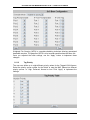
1
Managed 8-port 10/100 Mbps
plus 1-port 100-FX
Access Switch
NSH-5509
User Manual
(December 2007)
VOLKTEK NSH-5509 MANAGED 8-PORT 10/100 + 1-PORT 100-FX SWITCH
COPYRIGHT
All rights reserved. No part of this publication may be reproduced, stored in a retrieval system,
or transmitted in any form or by any means, whether electronic, mechanical, photo copying,
recording or otherwise, without the prior written permission of the publisher.
FCC WARNING
This equipment has been tested and found to comply with the limits for a class A device,
pursuant to part 15 of FCC rules. These limits are designed to provide reasonable protection
against harmful interference in a commercial installation. This equipment generates, uses and
can radiate radio frequency energy and, if not installed and used in accordance with the
instructions, may cause harmful interference to radio communication. Operation of this
equipment in a residential area is likely to cause harmful interference, in which case, the user
will be required to correct the interference at the user’s own expense.
CE
This is a Class A product. In a domestic environment, this product may cause radio interference
in which case the user may be required to take adequate measures.
Take special care to read and understand all the content in the warning boxes:
Warning
1
VOLKTEK NSH-5509 MANAGED 8-PORT 10/100 + 1-PORT 100-FX SWITCH
TABLE OF CONTENTS
1
ABOUT THIS GUIDE..........................................................................5
1.1
1.2
1.3
1.4
1.5
1.6
2
Welcome ............................................................................................................5
Purpose .............................................................................................................5
Terms/Usage .....................................................................................................5
Features.............................................................................................................5
Specifications ...................................................................................................6
Package Contents.............................................................................................7
HARDWARE DESCRIPTION .............................................................8
2.1
2.2
Product Illustration...........................................................................................8
Connectors........................................................................................................9
2.2.1
2.2.2
3
10/100Base-TX Ports .........................................................................................................9
100Base-FX Port ................................................................................................................9
INSTALLATION................................................................................10
3.1
3.2
3.3
3.4
3.5
3.6
3.7
3.8
3.9
Desktop installation........................................................................................ 10
Mounting on a rack ......................................................................................... 10
Getting Connected.......................................................................................... 10
Powering On the Unit ..................................................................................... 11
Connecting Fiber Cable.................................................................................. 11
Connecting Copper Cable.............................................................................. 11
Connecting the Console Port Cable.............................................................. 11
Connecting to computers or a LAN .............................................................. 12
Attaching the power adapter ......................................................................... 12
4
LED INDICATORS ...........................................................................13
5
ENHANCED FEATURES .................................................................14
5.1
6
CONFIGURATION............................................................................15
6.1
6.2
7
Overview of configuration options................................................................ 15
External SNMP-based network management application ........................... 15
MANAGEMENT VIA CONSOLE PORT ...........................................16
7.1
8
Xpress Ring..................................................................................................... 14
Connecting a HyperTerminal ......................................................................... 16
MANAGEMENT VIA INTERNET BROWSER INTERFACE.............19
2
VOLKTEK NSH-5509 MANAGED 8-PORT 10/100 + 1-PORT 100-FX SWITCH
8.1
8.2
Overview.......................................................................................................... 19
System Details ................................................................................................ 19
8.2.1
8.2.2
8.2.3
8.3
Homepage (System Details / System Info)....................................................................20
Board Info .........................................................................................................................21
DHCP Configuration ........................................................................................................22
Configuration .................................................................................................. 22
8.3.1
8.3.2
8.3.3
8.4
Port Configuration ...........................................................................................................23
Port Status........................................................................................................................24
Ethernet Loop Detection .................................................................................................24
Bridge Menu .................................................................................................... 25
8.4.1
8.4.2
8.4.3
8.4.4
8.5
Bridge Configuration (Enable / Disable RSTP, etc.).....................................................25
RSTP System Configuration...........................................................................................26
RSTP Per-Port Configuration .........................................................................................26
Xpress Ring Configuration .............................................................................................27
VLAN Menu...................................................................................................... 28
8.5.1
8.5.2
8.5.3
8.5.4
8.5.5
8.6
8.7
8.8
VLAN Type (VLAN Configuration)..................................................................................29
VLAN Configuration (Port-based) ..................................................................................29
Tag-based VLAN Port Configuration (Port Info)...........................................................30
Tag-based Info (VLAN Table) .........................................................................................31
Management VLAN ..........................................................................................................32
Rate Control .................................................................................................... 33
Port Mirroring.................................................................................................. 34
Trunk Configuration ....................................................................................... 34
8.8.1
8.8.2
8.8.3
8.9
Aggregator Setting ..........................................................................................................34
LACP Configuration ........................................................................................................35
LACP Link Status.............................................................................................................35
IGMP Menu ...................................................................................................... 36
8.9.1
8.9.2
8.10
MAC Menu ..................................................................................................... 37
8.10.1
8.10.2
8.10.3
8.10.4
8.11
Serial Port Configuration ..............................................................................................41
SNMP Configuration ..................................................................................... 42
8.13.1
8.13.2
8.14
8.15
8.16
8.17
8.18
8.19
8.20
8.21
8.22
Base Configuration........................................................................................................39
Tag Priority .....................................................................................................................40
IP ToS Priority ................................................................................................................41
Management Configuration ......................................................................... 41
8.12.1
8.13
MAC Table Status ..........................................................................................................37
Lock Learning MAC .......................................................................................................37
Static MAC Configuration .............................................................................................38
MAC Limit Configuration ..............................................................................................39
QoS Menu ...................................................................................................... 39
8.11.1
8.11.2
8.11.3
8.12
IGMP Configuration .........................................................................................................36
IGMP Groups Status........................................................................................................37
SNMP Communities.......................................................................................................42
IP Trap Manager .............................................................................................................42
E-mail Alarm Configuration ......................................................................... 43
User Configuration ....................................................................................... 44
Cable Test......................................................................................................44
Host Denial of Service .................................................................................. 45
Port Abnormal Traffic Detection.................................................................. 45
Firmware Download (Upgrade System) ...................................................... 46
Configuration File (System Backup) ........................................................... 47
System Restart Menu – Restart Option....................................................... 48
System Parameter Settings ......................................................................... 48
3
VOLKTEK NSH-5509 MANAGED 8-PORT 10/100 + 1-PORT 100-FX SWITCH
9
COMMAND LINE INTERFACE ........................................................49
9.1
9.2
9.3
Log in ............................................................................................................... 49
Show commands ............................................................................................ 49
System configurations ................................................................................... 50
9.3.1
9.3.2
9.3.3
9.3.4
Port configurations..........................................................................................................50
Spanning Tree Protocol (STP) configurations..............................................................51
Virtual LAN configurations .............................................................................................51
SNMP configurations ......................................................................................................52
10
TROUBLESHOOTING .....................................................................53
11
APPENDIX A ....................................................................................54
11.1
11.2
11.3
12
APPENDIX B ....................................................................................56
12.1
12.2
12.3
12.4
12.5
12.6
13
RJ-45 Cables ................................................................................................. 54
Console Cable (RJ-45 to DB-9) .................................................................... 54
SNMP Trap List ............................................................................................. 55
Command Mode Summary........................................................................... 56
Command Summary: User Mode (read privilege) ...................................... 56
Command Summary: Enable Mode (read/write privilege)......................... 56
Command Summary: Configuration Mode (read/write privilege) ............. 58
Command Summary: Interface Mode (read/write privilege)...................... 61
Command Summary: VLAN (802.1q) Mode (read/write privilege) ............ 63
CONTACT INFORMATION ..............................................................64
4
VOLKTEK NSH-5509 MANAGED 8-PORT 10/100 + 1-PORT 100-FX SWITCH
1
About This Guide
1.1
Welcome
Congratulations on choosing the NSH-5509 Managed 8-port 10/100Base-TX + 1-port
100-FX Access Switch. This device integrates 100Mbps Fast Ethernet and 10Mbps
Ethernet switching technologies with versatile management capabilities in a highly
flexible package. The device provides various management interfaces – including Web,
serial Console, Telnet, and Command Line (CLI).
1.2
Purpose
This guide discusses how to install and configure your Managed Access Switch.
1.3
Terms/Usage
In this guide, the term “Switch” (first letter upper case) refers to the NSH-5509 Switch,
and “switch” (first letter lower case) refers to other switches.
1.4
•
•
•
•
•
•
•
•
•
•
•
•
•
•
•
Features
Eight (8) 10/100Base-TX, one (1) 100Base-FX, and one (1) Console port (RJ-45)
SNMP management application software (HP Open View and IBM/Tivoli NetView
capable)
Http/Web browser user interface, CLI interface via console and telnet
Xpress Ring (redundant ring) with less than 50ms recovery time
Auto-negotiation NWay on copper Ethernet ports
Remote & local management
Extends fiber distances to 2km for multi-mode and up to 120km for long-haul singlemode fiber
WDM Single fiber optics
Status LEDs for quick and easy network activity monitoring
Firmware upgradeable
Console Port (RJ-45) for out-of-band device management. Configure the device
through a Terminal Emulator /TELNET Program
RJ-45 Ethernet Ports support auto MDI/MDI-X
Fiber Port: connect various fiber optic cables (multi-mode, single-mode, long-haul
single-mode, and WDM) to the fiber port
VLAN port isolation function to isolate downlink ports of a VLAN group, making the
Switch suitable as a remote access switch for cases where the operator needs to
service an MTU/MDU (Multiple Tenant Unit and Multiple Dwelling Unit – for example
an apartment building)
Port-based MAC limitation to restrict the number of MAC addresses learned on each
port – improves network security
5
VOLKTEK NSH-5509 MANAGED 8-PORT 10/100 + 1-PORT 100-FX SWITCH
•
1.5
FCC Class A & CE approved
Specifications
Standards:
IEEE 802.3 (10BASE-T Ethernet)
IEEE 802.3u (100BASE-TX Fast Ethernet)
IEEE 802.3x Flow Control
IEEE 802.3ad Port Trunking
IEEE 802.1d STP
IEEE 802.1w RSTP
IEEE 802.1q VLAN
IEEE 802.1p Priority Queues
Connectors:
1 x 100Base-FX (SC/ST)
8 x RJ-45 (10/100Mbps)
1 x RJ-45 (Console Port)
Management:
Out-of-band management via Console Port (RJ-45)
In-band management via RJ-45 and fiber ports
Cable Types:
UTP: (Cat 5/5e.)
Fiber: Multi-mode (62.5/125 micron)
Single-mode (9/125 micron)
Max. Distances:
Copper:
Fiber:
Data Rates:
Ethernet
Fast Ethernet
100 meters (Category 5/5e.)
2,000 meters (multi-mode)
Up to 120,000 meters (single mode)
10Mbps
100Mbps
Physical Characteristics
Power:
Power Input: 100~240V AC
-48VDC
+12VDC
Environment:
Operating:
Temperature: 0˚C to 50˚C
Relative Humidity: 10% to 80%, non-condensing
Non-Operating / Storage:
Temperature: -20˚C to 80˚C
Relative Humidity: 5% to 90%, non-condensing
6
VOLKTEK NSH-5509 MANAGED 8-PORT 10/100 + 1-PORT 100-FX SWITCH
Emissions:
FCC Part 15 of Class A & CE approved
Dimensions:
Dimensions 128 x 268 x 44 mm (D x W x H)
Safety:
EN 60950
Weight:
1200g
1.6
Package Contents
The package should include the following:
• One Managed Access Switch
• One console port cable (RJ45 to DB9)
• Protective caps for unused ports
• Four self-adhesive pads
• One AC power cord (optional adapter)
• User Manual CD
7
VOLKTEK NSH-5509 MANAGED 8-PORT 10/100 + 1-PORT 100-FX SWITCH
2
Hardware Description
The Switch was specially developed with a host of features that makes it particularly
suited for SOHO applications that demand the utmost in reliability. The Switch was
developed with “Xpress Ring” features. Xpress Ring offers recovery time of less than
50ms in case of network-link failure. This makes the Switch particularly suited for
applications that require super-fast recovery times and maintenance of service, ensures
"always-on" connectivity, eliminating costly network downtime.
Being SNMP-ready, the Switch enables network managers to remotely monitor the
entire network’s status quickly and easily via a network port, or a console port (out-ofband) connection. The Switch is designed with 'plug-n-play' features for hassle-free
integration into today's managed mixed-cabling network configurations, minimizing your
troubleshooting time.
Featuring Auto MDI/MDI-X detection for direct connection to a workstation, switch or hub,
network managers no longer need to worry about the cable configuration (cross-over or
straight through) when establishing connections between RJ-45 ports.
The Switch has auto-negotiation capabilities that allow it to support connection with
leading NWay switches.
2.1
Product Illustration
Front view of Switch:
Unit LEDs
Fiber port
Copper Ports
Console Port
Rear view of Switch:
Reset Button
Grounding Screw
8
Power Socket
VOLKTEK NSH-5509 MANAGED 8-PORT 10/100 + 1-PORT 100-FX SWITCH
2.2
Connectors
The Switch utilizes ports with copper and fiber port connectors functioning under
Ethernet/Fast Ethernet standards.
2.2.1
10/100Base-TX Ports
The 10/100BASE-TX ports support network speeds of either 10Mbps or 100Mbps, and
can operate in half- and full-duplex transfer modes. These ports also offer automatic
MDI/MDI-X crossover detection that delivers true “plug-n-play” capability – just plug the
network cables into the ports and the ports will adjust according to the end-node devices.
The following cabling is recommended for the RJ-45 connectors: (1)10Mbps – Cat 3 or
better; (2)100Mbps – Cat 5 or better.
2.2.2
100Base-FX Port
The 100Base-FX port adds a fiber Fast Ethernet link to your network device. Compliant
with IEEE 802.3u, this port can transmit data at 100Mbps in full-duplex mode across
distances of up to 2km (with multi-mode) and up to 120km (with single-mode fiber-optic
cable). The fiber ports have a choice of 2 fiber connector types: ST and SC.
9
VOLKTEK NSH-5509 MANAGED 8-PORT 10/100 + 1-PORT 100-FX SWITCH
3
Installation
The location chosen for installing the Switch may greatly affect its performance. When
selecting a site, we recommend considering the following rules:
3.1
•
Install the Switch in an appropriate place. See Technical Specifications for the
acceptable temperature and humidity ranges.
•
Install the Switch in a location that is not affected by strong electromagnetic field
generators (such as motors), vibration, dust, and direct sunlight.
•
Leave at least 10cm of space at the front and rear of the unit for ventilation.
•
Affix the provided rubber pads to the bottom of the Switch to protect the case
from scratching.
Desktop installation
Follow the instructions listed below to install the Switch in a desktop location.
1. Locate the Switch in a clean, flat and safe position that has convenient access to
AC power.
2. Separate the four (4) self-adhesive rubber pads and attach them to the underside
of the Switch.
3. Apply AC power to the Switch. (The green PWR LED on the front panel should
light up).
4. Connect cables from the network partner devices to the ports on the front panel.
(The green LNK LED on the front panel associated with the port should light).
This Switch can also be mounted on a vertical surface. Simply use the
underside of the unit as a template to measure and mark out the position of the
holes on to the surface where the unit is to be installed. Then use the two
screws provided to mount the Switch firmly in place.
Warning: Because invisible laser radiation may be emitted from the aperture of the
port when no cable is connected, avoid exposure to laser radiation and do not stare
into open apertures.
3.2
Mounting on a rack
Attach brackets to each side of the switch and place the brackets in the rack’s slots.
Insert and tighten two screws to securely attach the bracket to the rack on each side.
3.3
Getting Connected
The Switch is capable of connecting up to 9 network devices employing a combination of
twisted-pair and fiber cabling paths at Ethernet or Fast Ethernet speeds.
10
VOLKTEK NSH-5509 MANAGED 8-PORT 10/100 + 1-PORT 100-FX SWITCH
3.4
Powering On the Unit
The Switch uses an AC 100~240V or DC power supply of 9~32V DC. The power and
redundant power connection is provided via a terminal block located at the top of the
Switch. The Switch’s power supply automatically self-adjusts to the local power source
and may be powered on without having any or all LAN segment cables connected.
Check the front-panel LEDs as the device is powered on to verify that the Power
LED is lit. If not, check that the power cable is correctly and securely plugged in.
3.5
Connecting Fiber Cable
When connecting a fiber cable to the 100BASE-FX port on the Switch, be sure the
correct type of connector (ST or SC) is used. Follow the steps below to properly connect
fiber cabling:
1. Remove and keep the fiber port’s (ST/SC) rubber covers. When not connected
to a fiber cable, the rubber cover should be replaced to protect the fiber optics.
2. Check that the fiber terminators are clean. You can clean the cable plugs by
wiping them gently with a clean tissue or cotton ball moistened with a little
ethanol. Dirty fiber terminators on fiber optic cables will impair the quality of the
light transmitted through the cable and lead to degraded performance on the
port.
3. Connect one end of the cable to the ST/SC port on the Switch and the other
end to the fiber port of the other device.
Note: When inserting the cable, be sure the tab on the plug clicks into
position to ensure that it is properly seated.
Check the corresponding port LED on the Switch to be sure that the connection is valid.
(Refer to the LED chart).
3.6
Connecting Copper Cable
The 10/100Base-T RJ-45 Ethernet ports fully support auto-sensing and auto-negotiation.
1. Insert one end of a Category 3/4/5/5e (see recommendation above) type twistedpair cable into an available RJ-45 port on the Switch and the other end into the
port of the network node.
2. Check the corresponding port LED on the Switch to ensure that the connection is
valid. (Refer to LED chart)
3.7
Connecting the Console Port Cable
The console port (DB-9) provides the out-of-band management facility.
1
Use null modem cable to connect the console port on the Switch and the other
end into the COM port of the computer.
11
VOLKTEK NSH-5509 MANAGED 8-PORT 10/100 + 1-PORT 100-FX SWITCH
2
Insert the RJ-45 side of the (8-pin RJ-45 to DB-9) cable into the RJ-45
console port on the Switch and the other end into the COM port of the
computer.
3
Configure the Hyper Terminal settings as mentioned in chapter 7.
For console port (8 pin RJ-45) pin assignment, please see Appendix A.
3.8
Connecting to computers or a LAN
You can use Ethernet cables to connect computers directly to the Switch ports. You can
also connect hubs/switches to the switch ports by Ethernet cables. You can use either
crossover or straight-through Ethernet cables to connect computers, hubs, or switches.
3.9
Attaching the power adapter
Connect the AC power cord to the POWER receptacle on the back of the Switch and
plug the other end of the power cord into a wall outlet or a power strip.
Check the front LED indicators with the description in the next chapter. If the LEDs light
up as described, the Switch’s hardware is working properly.
12
VOLKTEK NSH-5509 MANAGED 8-PORT 10/100 + 1-PORT 100-FX SWITCH
4
LED Indicators
This Switch is equipped with Unit LEDs to enable you to determine the status of the
Switch, as well as Port LEDs to display what is happening in all your connections. They
are as follows:
Unit LEDs
LED
Condition
PWR
On (Green)
Switch uses primary power
Off
Primary power off or failure
Flashing
(Green)
On
Indicating POST function upon start-up
100 (1 to 8 Copper
th
Ports and 9 Fiber Port)
On (Green)
Port operating at 100Mbps
Off
Port operating at below 100Mbps
st
On (Green)
Illuminated when the port is connected with compliant device
Flashing
(Green)
Off
Data traffic passing through port
POST
st
th
th
LNK/ACT (1 to 8
th
Copper Ports and 9
Fiber Port)
Status
POST function successfully performed
No valid link established on port
NOTE 1: The fiber module does not support “half-duplex” mode.
13
VOLKTEK NSH-5509 MANAGED 8-PORT 10/100 + 1-PORT 100-FX SWITCH
5
Enhanced Features
5.1
Xpress Ring
Xpress Ring is a VOLKTEK proprietary ring protocol that enables networks to recover
from link failure within 50ms. To enable Xpress Ring, it needs some network
configuration: the user must assign two ring ports for each Switch in the ring. The user
must also assign the Arbiter Switch which will decide if it is necessary to activate the
backup path. For Xpress Ring, any switch can be the arbiter – just remember that the
Arbiter Switch must be part of the ring.
Apart from rerouting the transmission within 50ms, the Arbiter Switch will also issue an
alarm when a link failure occurs. The user will then be informed of the failure and will be
able to fix the problem and reconfigure if required.
Xpress Ring is the fastest ring recovery technology and is ideal for networks where the
ring topology is not changed very often.
For configuration of Xpress Rings, please refer to the appropriate chapter in this manual.
14
VOLKTEK NSH-5509 MANAGED 8-PORT 10/100 + 1-PORT 100-FX SWITCH
6
Configuration
6.1
Overview of configuration options
For advanced management capabilities, the onboard management agent provides CLI
interface configuration programs. These programs can be accessed by a direct or
modem connection to the console port on the front panel (out-of-band), or by a Telnet
connection over the network (in-band).
The management agent is based on SNMP (Simple Network Management Protocol).
This SNMP agent permits the switch to be managed from any PC in the network by
using in-band management software.
The management agent also includes an embedded HTTP Web agent. This Web agent
can be accessed using a standard Web browser from any computer attached to the
network.
The switch gives you the flexibility to access and manage it by using any or all of the
methods described. The administration console and web browser interfaces are
embedded in the Switch software and can be used immediately after setup.
6.2
External SNMP-based network management application
Advantages
‧
Communicates with Switch functions at the MIB level
‧
Based on open standards
The two methods for configuring the Switch management agent are explained in the
following chapters.
The first method – Command Line Interface (CLI) via the Console Port to initially set IP
parameters.
The second is the use of an Internet Browser Interface to configure the Switch.
15
VOLKTEK NSH-5509 MANAGED 8-PORT 10/100 + 1-PORT 100-FX SWITCH
7
Management via Console Port
Out-of-Band Connection
Prior to accessing the switch’s onboard agent via a network connection, you must first
configure it with a valid IP address, subnet mask, and default gateway using an out-ofband connection or the BOOTP protocol.
After configuring the switch’s IP parameters, you can access the onboard configuration
program from anywhere within the attached network or via the internet. The onboard
configuration program can be accessed using Telnet from any computer attached to the
network. It can also be managed from any computer using a Web browser (Internet
Explorer 4.0 or above, or Netscape Navigator 4.0 or above).
Access the Switch via a terminal emulator (such as Hyper Terminal) attached to the
console port. The console port is set at the factory with the following default COM port
properties. Configure your own terminal to match the following:
Baud rate:
38,400
Data size:
8bits
Parity:
None
Stop bits:
1
Flow Control:
None
Note: Ensure that the terminal or PC you are using to make this connection is configured
to match the above settings. Otherwise the connection will not work.
A console port cable is provided with the Switch to connect the PC’s COM port with the
switch’s serial console (RJ-45) port. Please see Appendix A for cable pin assignment
details.
7.1
Connecting a HyperTerminal
Prior to following the instructions listed below for HyperTerminal, verify that a
console cable (RJ45 to DB9) connection between the Switch and work station exists.
Then follow the steps below:
1. Launch the terminal emulation program on the remote workstation and power on
the Switch. Be sure to select the correct COM port.
16
VOLKTEK NSH-5509 MANAGED 8-PORT 10/100 + 1-PORT 100-FX SWITCH
2. Enter the correct parameters according to the defaults given above.
1.
The following screen will appear on your monitor.
VOLKTEK Corporation
System version: 1.00.00 (built at Dec 3 2007 10:10:58)
Username:
2.
The default log-in name is “admin” with no preset password.
The system provides CLI user interface via console or telnet. After you log into
the system, the default privilege level is read only, displayed with the “>” prompt.
Username: admin
Password:
NSH-5509>
3.
Type “enable” and press “Enter” to turn on read/write privileged command
mode.
NSH-5509> enable
NSH-5509#
After log-in, type the following command to change the device’s IP address, Network
Mask and Gateway Address:
NSH-5509# config terminal
NSH-5509(config)# ip xxx.xxx.xxx.xxx
NSH-5509(config)# netmask xxx.xxx.xxx.xxx
NSH-5509(config)# gateway xxx.xxx.xxx.xxx
17
VOLKTEK NSH-5509 MANAGED 8-PORT 10/100 + 1-PORT 100-FX SWITCH
The xxx’s represent values between 0 and 255 and the user should enter their own IP
address in this form. The configuration program will not accept anything outside this
format. Remember to separate each part of the address with a period (dot). For example:
NSH-5509# config terminal
NSH-5509(config)# ip 192.168.99.222
NSH-5509(config)# netmask 255.255.255.0
NSH-5509(config)# gateway 192.168.99.1
4. These system parameters are invalid until you save configuration with “write
memory” command. After you enter “write memory” command, the system will
auto restart immediately.
NSH-5509(config)# exit
NSH-5509# write memory
It takes a few moments to write memory...
NSH-5509# write memory $$$ Restart system....!!!
After the system restarts completely, you can type in “show ip” command to verify
system settings.
NSH-5509# show ip
[eth0] Network Configuration:
MAC Address : 00:0B:04:09:03:07
DHCP Client: Disabled
IP Address: 192.168.99.222
Netmask
: 255.255.255.0
Gateway
: 192.168.99.1
When the address has been changed, please make a note of the new address, and
keep it in a safe place. With HyperTerminal, the command lines are the same as that for
telnet.
Note: IP addresses are unique. If an address isn’t available, please contact the
appropriate authorities to apply for one.
18
VOLKTEK NSH-5509 MANAGED 8-PORT 10/100 + 1-PORT 100-FX SWITCH
8
Management via Internet Browser Interface
8.1
Overview
This section gives a step-by-step guide to configuring the Switch’s management
functions. A series of screen shots and instructions illustrate the main menu structure
and how it works.
Firstly, open a web browser and key in the Switch’s IP address – then press Enter. A
Web Manager page like this will pop up on your screen:
Log in
The default username is: admin
There is no preset password for this device, so click on “OK” to proceed.
8.2
System Details
When your Web browser connects with the Switch’s Web agent, the home page is
displayed as shown below. The home page displays the Main Menu on the left side of
the screen and System Information as the main page. The Main Menu links are used to
navigate to other menus and display configuration parameters and statistics.
19
VOLKTEK NSH-5509 MANAGED 8-PORT 10/100 + 1-PORT 100-FX SWITCH
8.2.1 Homepage (System Details / System Info)
Click on each parameter field to modify the specific settings, click “Undo” to restore
previously saved configurations or click “Apply” to implement newly entered information.
If you change the settings of “IP Address”, “Subnet Mask”, and “Gateway” on “System
information” page, and click “Apply” to implement settings. The system will notify you to
save these settings with a pop-on dialog box.
To save this configuration to flash memory, click “Saving Settings” on the bottom of
“Main Menu”, it will link to saving page, then click the “Save" button.
**Note:
If you change the settings of ‘IP Address’, ‘Subnet Mask’, and ‘Gateway’ on the
‘System information’ page, or DHCP setting on ‘DHCP configuration’ page, you
must save these parameters in order for them to come into effect after you click
20
VOLKTEK NSH-5509 MANAGED 8-PORT 10/100 + 1-PORT 100-FX SWITCH
the ‘Apply’ button. The system will auto restart after you click ‘Save’ button on the
Save Settings page.
Other parameters on any page will come into effect immediately after you click
‘Apply’ button, but will not be saved to flash memory until you go to the Save
Settings page and click the ‘Save’ button. In this case, the system will not restart.
The system information is described below:
Parameter
Description
Description
Provides description of the Switch
Object ID
ID or Serial number
Up Time
Provides information on up time, or the time that the system has
been operating
System Name
Modifies the name of the Switch
Contact
Enter a contact name
Location
Enter the location of Switch
DHCP Client
Disabled or client’s name
IP Address
Default: 192.168.0.254
Subnet Mask
Default: 255.255.255.0
Gateway
Default: 192.168.0.1
Note:
The above are factory defaults used as an example only. A new address is important. Choose
numbers between 0 and 254 in each sub-address field. Make a note of them and keep the details
in a safe place. In writing this manual we used IP address 192.168.0.201 and Subnet Mask
(255.255.0.0).
8.2.2 Board Info
This page displays version information about system’s hardware and firmware.
Parameter
Hardware Version
Description
Provides information on the hardware version
Firmware Version
Provides information on the firmware version
Port Number
Provides information on the number of ports available
21
VOLKTEK NSH-5509 MANAGED 8-PORT 10/100 + 1-PORT 100-FX SWITCH
8.2.3 DHCP Configuration
Disable or enable the DHCP Client role of the Switch. Once the DHCP Client is enabled,
the IP address of the Switch is obtained from DHCP Server and you need to check the
new IP address via the Serial Console.
If you change the setting of “DHCP Client”, and click “Apply”, the system will notify you to
save the setting with a pop-up dialog box.
8.3
Configuration
Port Configuration
This section allows you to view and change the parameter settings for the individual
ports on the Switch. See screen shot and table below for adjustable parameters.
22
VOLKTEK NSH-5509 MANAGED 8-PORT 10/100 + 1-PORT 100-FX SWITCH
8.3.1 Port Configuration
Click on each parameter field to modify the desired setting, then click “Undo” to restore
previously saved configurations or click “Apply” to implement newly entered information.
See description below:
Parameter
Description
Port
Port type and number
Name
Assign a name to each port to keep record of your connections
Type
Type of connector for each port (auto-detects fiber or RJ-45)
Admin
Enable or disable admin configurations
Speed: Status
Speed: Setting
Provides information on speed at which ports are currently operating
Set speed for RJ-45 ports. (The speed for fiber ports is fixed)
Duplex: Status
Duplex: Setting
Provides information on Duplex Status
Select half / full duplex modes
Link
Provides information on link status
Auto
Enable / Disable Auto-negotiation on copper ports
Flow Control
Enable / Disable flow control for each port
Note:
Disable the Auto (Auto-negotiation) function to configure Speed and Duplex. Click on “Undo” to
restore previously saved configurations or click on “Apply” to implement newly entered
information.
23
VOLKTEK NSH-5509 MANAGED 8-PORT 10/100 + 1-PORT 100-FX SWITCH
8.3.2 Port Status
This window offers at-a-glance status reporting for Switch operations. Click on the “Port
Configuration” button to return to the “Port Configuration” window if you need to change
any settings.
8.3.3 Ethernet Loop Detection
Ethernet Loop Detection is used to detect Ethernet Loop conditions on active ports.
Ethernet Loops cause broadcast storms and crash the whole network. Set “Protection”
to enable or disable the Ethernet Loop Detection function of the Switch, and enable or
disable it on the specific port. For MAC Address, users can use the default one as the
destination MAC address for Ethernet Loop Detection. The default MAC Address is a
multicast address. Some network switch does not forward packets with unrecognized
multicast MAC address and discard those test packets sent out by the Switch for
Ethernet Loop Detection. In this situation, the function cannot be correctly executed.
Users can set another unicast MAC Address to cope with this condition. If the port is
blocked by Switch for detected loop, it needs to be enabled manually after removing the
Ethernet Loop.
24
VOLKTEK NSH-5509 MANAGED 8-PORT 10/100 + 1-PORT 100-FX SWITCH
8.4
Bridge Menu
The Bridge menu is used for configuring the Spanning Tree Algorithm and Xpress Ring
settings, as well as the traffic class priority threshold and the address aging time.
Xpress Ring offers a very fast link-failure recovery time of 50ms, user must select the
role of the Switch (arbiter or forward) and which two ports will be part of the Xpress Ring
network.
The Spanning Tree Algorithm is used for detecting and disabling network loops, and to
provide backup links between switches, bridges or routers. This allows the switch to
communicate and interact with other bridging devices (i.e. STA-compliant devices) in a
network to ensure that only one route exists between any two stations, and it provides
redundant or backup links that automatically take over when a primary link goes down.
8.4.1 Bridge Configuration (Enable / Disable RSTP, etc.)
Select the appropriate mode (protocol) for your network implementation, then click
“Apply” to implement newly entered information, or click “Undo” to restore previously
saved configurations.
Parameter
Description
Disable
Don’t enable RSTP or Xpress Ring
RSTP (802.1W)
Enable Rapid Spanning Tree Protocol
Xpress Ring
Enable Xpress Ring function, redundant link with fastest recovery time: less
than 50ms
Port 1~9
Enable (V): This port participates in the STP/RSTP algorithm execution of
the Switch when RSTP (802.1W) is enabled.
Disable (_): This port doesn't participate in the STP/RSTP algorithm
execution of the Switch when RSTP (802.1W) is enabled.
25
VOLKTEK NSH-5509 MANAGED 8-PORT 10/100 + 1-PORT 100-FX SWITCH
8.4.2 RSTP System Configuration
This screen allows the user to enter the RSTP parameters for the Switch. Please note:
users must select “RSTP (802.1W)” under Bridge Configuration to perform this
configuration. Otherwise, this option will not be accessible.
Enter the appropriate values, then click on “Apply” to implement newly entered
information or click on “Undo” to restore previously saved configurations.
Parameter
Description
RSTP Force Version
Force the spanning tree algorithm to run on “RTP” or “RSTP” protocol
version
Bridge Priority
Set the bridge priority. The limit is given between 0 (the highest
priority) and 65535 (the lowest priority).
Bridge priority is used in selecting the root device, root port, and
designated port. The device with the highest priority becomes the STA
root device. However, if all devices have the same priority, the device
with the lowest MAC address will then become the root device.
Hello Time
Set the interval between hello bridge protocol data units (BPDUs) sent
by root switch configuration messages.
The limit given is from 1 – 10 seconds.
Max. age
Set the interval between messages that the spanning tree receives
from the root switch. If a switch does not receive a bridge protocol data
unit (BPDU) message from the root switch within this interval, it will
reconfigure the spanning-tree topology. The limit given is from 6 – 40
seconds.
Forward Delay
Set Forward Delay. The limit given is from 4~30 seconds. The
forwarding time specifies how long each of the listening and learning
states last before the port begins forwarding.
8.4.3 RSTP Per-Port Configuration
STP/RSTP allows the Switch to assign a priority status to each of its ports, with respect
to other networking nodes in the network. In other words, STP/RSTP determines the best
link for data to flow, given the priority level of each node on the network. Ensure that this
function is activated to avoid collisions and when setting up backup links.
26
VOLKTEK NSH-5509 MANAGED 8-PORT 10/100 + 1-PORT 100-FX SWITCH
Click on each parameter field to modify the desired setting, then click on “Undo” to
restore previously saved configurations or click on “Apply” to retain newly entered
information. See description below:
Parameter
Description
Port Type Priority
Set the priority of each port. The limit given is from 1 – 255. The
lowest number means highest priority. The default priority is set to
128 – the midpoint of this limit
Cost
Set the cost assigned to each port. This will determine the route of
information flow. The higher the cost the less suitable the port is to be
a node for the STP.
Edge
On: the port is connected to an end node, e.g., a network card
installed in a PC
Off: the port is connected to a bridged node
P2P
On: the link type of the port is Point-to-Point, connecting to one Bridge
Off: the link type of the port is Shared Medium, connecting to multiple
Bridges
Auto: the link type is automatically determined
8.4.4 Xpress Ring Configuration
If Xpress Ring was enabled, you must set the Switch’s role in the Xpress Ring network
and the ports that will be part of the Xpress Ring. Every switch participated the Xpress
Ring environment should be exactly defined.
27
VOLKTEK NSH-5509 MANAGED 8-PORT 10/100 + 1-PORT 100-FX SWITCH
Xpress Ring Role
Arbiter – the Switch which receives status reports submitted from other Switches of the
ring and determines ring recovery behavior.
Forward – the Switch which is not the Arbiter of the ring and will forward the received
status reports on the other side of ring ports.
Select Ring Port-1: the first port composes the Xpress Ring of this switch.
Select Ring Port-2: the second port composes the Xpress Ring of this switch.
Port status: display the port status. “Forwarding” means packets transmitting and
receiving were at normal status on this port, “Blocking” means this port was disabled or
link was down.
8.5
VLAN Menu
A VLAN is a network of computers behaving as though they are connected to the same
segment, even though their physical location may be on a different segment of a LAN
altogether. VLANs are configured through software rather than hardware, which make
them extremely flexible.
Some of the advantages of VLANs are:
• When a computer is physically moved to another location, it can stay on the same
VLAN without any hardware reconfiguration because VLANs are not limited by
hardware constraints.
• VLANs can be configured to define a network into various logical configurations. For
example, VLANs can define a network by application. In this scenario, a company
might create one VLAN for multimedia users and another for e-mail users.
• VLANs can also define a network by department. For example, a company might
have one VLAN for its Engineering Department, another for its Marketing
Department, and another for its Sales Department.
• VLANs can also be set up according to the organization’s internal structure. For
example, the company president might have his/her own VLAN, the executive staff
28
VOLKTEK NSH-5509 MANAGED 8-PORT 10/100 + 1-PORT 100-FX SWITCH
might have a different VLAN, and the remaining employees might have yet a
different VLAN.
As these examples show, VLANs offer incomparable flexibility. The following section
describes how VLANs can be deployed using the Switch.
8.5.1 VLAN Type (VLAN Configuration)
The “VLAN Type” menu let users select the VLAN type of the Switch.
Parameter
Description
Disabled
The VLAN function is disabled.
Port-Based
Tag-Based
The VLAN function is enabled for Port-based VLANs.
The VLAN function is enabled for IEEE802.1Q VLANs
8.5.2 VLAN Configuration (Port-based)
The “Port-based” menu is for configuration of Port-Based VLAN. It is enabled only when
the VLAN Type is set as “Port-Based”.
29
VOLKTEK NSH-5509 MANAGED 8-PORT 10/100 + 1-PORT 100-FX SWITCH
For each port the user must click on the checkboxes of the ports to decide which port is
allowed to switch frames from the configured port. Click on “Apply” to implement newly
entered information or click on “Undo” to restore previously saved configurations.
Enable / Disable Switch Management:
Enable: The user can manage the Switch as Web/Telnet Client or SNMP Manager via
this port.
Disable: The Switch is not manageable from Web/Telnet Client or SNMP Manager via
this port.
8.5.3 Tag-based VLAN Port Configuration (Port Info)
The menu “Tag-Based” is for configuration of Tag-Based VLAN. It is enabled only when
the VLAN Type is set as “Tag-Based”. The sub-menu lets users configure the way in
which each port treats the incoming frames that are marked for Tag-based VLANs.
Parameter
Description
VID
Set the VLAN ID. The limit is 1 to 4095. The VLAN ID is assigned to all
untagged frames received on this port.
Priority
Set VLAN Priority. The limit given is between 0 – 7. 0 is the lowest priority
and 7 is the highest priority.
Ingress Filter 1
(Non-Member)
and Filter 2
(Untagged)
z
z
z
Non-Member (1): Forward and Untagged (2): Forward
− Forward the VLAN-tagged frames that are not members of any VLAN
in which the port is participating, and forward all untagged frames.
Non-Member (1): Drop and Untagged (2): Forward
− Drop the VLAN-tagged frames which are not members of any VLAN
of which the port is participating, and forward all untagged frames.
Non-Member (1): Drop and Untagged (2): Drop
− Drop the VLAN-tagged frames which are not members of any VLAN
of which the port is participating, and drop all untagged frames.
30
VOLKTEK NSH-5509 MANAGED 8-PORT 10/100 + 1-PORT 100-FX SWITCH
Isolation
Enable – The port is isolated. Isolated ports belonging to the same VLAN do
not communicate with each other – this is generally set for security reasons.
The isolated ports communicate only with the trunk ports, which should NOT
be set as “isolated”.
Disable – The port is not isolated and can communicate with all ports of the
VLANs.
Double Tag
Enable: The egress frames are double-tagged.
Disable: The egress frames are not double-tagged.
8.5.4 Tag-based Info (VLAN Table)
The sub-menu “Tag-based Info” let users add, modify, or delete entries in the Tag-based
VLAN Table, the configurations of 802.1Q VLANs and the participating ports. Up to 64
VLANs can be configured on the Switch.
On the left is the Tag-based VLAN Table, where existing VLANs can be modified or
deleted. In the combo box at the top is the VLAN ID (VID) numbers (1, 2, etc.) of the
previously configured VLANs. Users can click on a VID number to display the port
information of that VLAN. The following table describes the port parameters in regard to
802.1Q VLANs:
31
VOLKTEK NSH-5509 MANAGED 8-PORT 10/100 + 1-PORT 100-FX SWITCH
Parameter
Member
Description
The Port is a member of the specified VLAN and the frames of this VLAN
can be switched through this port, but the tagging information in the frame
header is not modified by the Switch.
Untagging
The port is an untagging port (as defined in 802.1Q) that is participating in
the VLAN. In such an untagged port the Switch will strip off the 802.1Q tag
from the incoming and outgoing frames if they are tagged in such a way.
This is used for sending frames to non-802.1Q-compliant devices.
Tagging
The port is a tagging port (as defined in 802.1Q) and is participating in the
VLAN. The Switch will put the VLAN information of the port – including VID
and Priority – into the header of the untagged frames coming in or
transmitted from the port. The tagged VLAN information in the frames can
later be used by other 802.1Q-compliant devices for forwarding decisions.
Non-member
The port is not participating in the VLAN as identified by the selected VID
(VLAN ID).
Click the “Modify” button to modify configurations of the selected VLAN according to the
settings on the table.
Click the “Delete” button to delete the VLAN entries of the selected VID.
On the right is the “Add VLAN Configuration” work area where you can add VLAN
configuration entries onto the Tagging VLAN Table. Enter a valid configurable 802.1Q
VID ranging from 1 ~ 4094 into the field on the first row. Next, specify for each port the
parameters described in the table above – this will decide if the specific port will
participate in that specific VID and how it will participate. Click the “Apply” button to add
the new VLAN to the Tag-based VLAN Table.
8.5.5 Management VLAN
The Management VLAN is the VLAN ID that in-band management stations belong to.
The Port VLAN ID of the port that receives the management messages must be the
same as the Management VLAN ID. The Web or Telnet session will be disconnected
after the Management VLAN is changed.
32
VOLKTEK NSH-5509 MANAGED 8-PORT 10/100 + 1-PORT 100-FX SWITCH
8.6
Rate Control
Use this screen to set the Jumbo packet limit and the Rate Control for each port of the
Switch.
Click on each parameter field to modify the desired setting, then click “Apply” to
implement newly entered information or click “Undo” to restore previously saved
configurations.
Note: The maximum limited rate is 64Mbps.
Parameter
Description
Port Ingress Limit Mode
Select to block the specified traffic from the port.
All Frames: – Restrict all kinds of packets (Default) exceeding the
rate set in the Ingress/Egress Rate fields
Multicast/Broadcast & Flooded unicast: – Restrict these packets
when exceeding the set value
Multicast/Broadcast only: – Restrict these packets when exceeding
the assigned value
Broadcast only: – Restrict broadcast only packets when exceeding
the assigned limit
Ingress / Egress Rate
Set the threshold of traffic of limited packets for each port in the
Switch
33
VOLKTEK NSH-5509 MANAGED 8-PORT 10/100 + 1-PORT 100-FX SWITCH
8.7
Port Mirroring
Set the port mirroring option to monitor data being transmitted through a specific port.
Click on each parameter field to modify the desired setting, then click “Apply” to
implement newly entered information or click “Undo” to restore previously saved
configurations.
Parameter
Mirroring Mode
Description
Select appropriate mode
Disable: – Mirror mode is disabled
Ingress & Egress: – Monitor both incoming and outgoing traffic
Egress: – Monitor only outgoing traffic
Monitoring Port
Select the port which will do the monitoring
Monitored Port
Select the port that needs to be monitored
8.8
Trunk Configuration
8.8.1 Aggregator Setting
34
VOLKTEK NSH-5509 MANAGED 8-PORT 10/100 + 1-PORT 100-FX SWITCH
Port Trunking defines a network link aggregation and trunking method which specifies
how to create a single high-speed logical link that combines several low-speed physical
links. Use the Trunk Configuration page shown above to create trunk groups. The Switch
supports a maximum of four trunk groups for 100Mbps ports. Each trunk group in groups
1~4 may be comprised of up to four ports, selected from any combination of 100Mbps
ports.
Note: Before you configure trunk group, check the setting of bridge function. If bridge
function has been enabled, the system will display an error message when you click
“Apply”.
Error: Cannot save while Bridge Function is enabled.
If the trunk group formed with another switch using protocol-based LACP, click to enable
“LACP”.
8.8.2 LACP Configuration
“Port State Activity” will determine whether the port will actively initiate the LACP
negotiation. Enable “Active” if the port is active for LACP negotiation.
System priority is combined with the Switch’s MAC address to form the Link Aggregation
Group (LAG) ID. This ID is used to indicate a specific LAG during LACP negotiations
with other systems.
8.8.3 LACP Link Status
35
VOLKTEK NSH-5509 MANAGED 8-PORT 10/100 + 1-PORT 100-FX SWITCH
This window displays the LACP Link Status, including System Priority, MAC address,
Port ID, Port Key, and Port Priority of Actor and Partner roles of the formed LACP
groups.
8.9
IGMP Menu
Using the IGMP Menu
The IGMP menu is used for configuring IGMP snooping. IGMP means "Internet Group
Management Protocol". It is a protocol through which hosts can register with their local
router for multicast services. If there is more than one multicast router on a given subnetwork, one of the routers is elected and assumes the responsibility of keeping track of
group membership.
8.9.1 IGMP Configuration
This menu allows the user to Enable/Disable IGMP Snooping and IGMP Query.
Port 1~9 IGMP Static:
Enable (V): Multicast packets will be forwarded to IGMP Static ports without the learning
process and timeout of multicast group membership. It is generally applied to those ports
of uplinks or A / V equipment which will not be flexibly reconfigured.
Note: In order to keep the switch traffic efficient, the last byte of the IP address should
not be the same as in the IGMP group. E.g. if the Switch’s IP address is 192.168.0.10
and the IGMP router / switch’s IP address is 192.168.21.10, this will make the switch
less efficient.
36
VOLKTEK NSH-5509 MANAGED 8-PORT 10/100 + 1-PORT 100-FX SWITCH
8.9.2 IGMP Groups Status
This window will display the IGMP group status of the port members if IGMP traffic is
present.
8.10
MAC Menu
The MAC menu will enable the following configurations:
8.10.1
MAC Table Status
The user can view the MAC Table by selecting this function. On this page the mark “P”
means the MAC is learned from a downlink port and the mark “T” means the MAC is
learned from a trunk port.
8.10.2
Lock Learning MAC
The user can stop specific port(s) from learning MAC addresses. Select the port(s) that
need to be locked so that they cannot learn MAC addresses.
37
VOLKTEK NSH-5509 MANAGED 8-PORT 10/100 + 1-PORT 100-FX SWITCH
8.10.3
Static MAC Configuration
Here the user can select a static MAC configuration for certain port(s) of the Switch.
Add the valid MAC address in the MAC field, then select the priority and port number.
Press “Apply” to implement the input. If you want to deny a host to access network via
this switch, type in the MAC address and select “none” at port number field.
The Static MAC addresses and their settings will be displayed in the table below the
input bar. Press “Delete” to void the configuration.
38
VOLKTEK NSH-5509 MANAGED 8-PORT 10/100 + 1-PORT 100-FX SWITCH
8.10.4
MAC Limit Configuration
The “MAC Limit Configuration” menu lets the user limit the number of incoming MAC
addresses per port. If the user wants to disable this function, select “Disable” from the
combo box “Mac Limit Function” on the upper left. The Limit Quantity range is 1~20 per
port. The MAC addresses learned are recorded on a per-port basis. Only the frames with
such recorded MAC addresses will be forwarded. This learning process will be
conducted every three minutes. So, if users change the NIC of the PC or IP appliance,
the new MAC address will be learned in three minutes by the Switch, within the set
quantity limitations. The MAC Limit Function can be disabled or enabled per port, under
the parameter labeled “Action” in the table. Generally this function is only enabled for
downlink ports.
8.11
QoS Menu
QoS (Quality of Service) refers to the mechanisms in the Switch’s network software that
make the actual determinations of which packets have priority. The Switch supports
advanced QoS features like scheduling, classification and policing.
8.11.1
Base Configuration
This window offers user to perform the basic configuration for Quality of Service.
Schedule Mode: “weighted fair queuing” or “all high before low”
39
VOLKTEK NSH-5509 MANAGED 8-PORT 10/100 + 1-PORT 100-FX SWITCH
Weighted Fair Queuing (WFQ) is a packet-scheduling technique allowing guaranteed
bandwidth services. The purpose of WFQ is to let several sessions share the same link.
Once you adjusted the basic settings, use the “Apply” button to implement these
changes.
8.11.2
Tag Priority
The user can define up to eight different priority values for the Tagged VLAN frames.
Select the priority queue number for the Switch to map the MAC frames into different
priority queues: i.e. High, Preferred, Normal or Low. Click “Apply” to implement the
settings.
40
VOLKTEK NSH-5509 MANAGED 8-PORT 10/100 + 1-PORT 100-FX SWITCH
8.11.3
IP ToS Priority
The IP ToS (Type of Service) Priority menu provides different priorities. The user can
select the most suitable combination.
8.12
Management Configuration
8.12.1
Serial Port Configuration
Here the user can see the serial port configuration that can be utilized while accessing
the switch via Console port.
Click on each parameter field to modify the desired setting, then click “Apply” to
implement newly entered information or click “Undo” to restore previously saved
configurations.
Parameter
Description
Management Mode,
Baud Rate, Data Bits,
Stop bits, Parity
Default COM port properties
Time Out
Set the time (seconds) for auto-logout in case there is no activity for
that time period
41
VOLKTEK NSH-5509 MANAGED 8-PORT 10/100 + 1-PORT 100-FX SWITCH
8.13
SNMP Configuration
8.13.1
SNMP Communities
Click on each parameter field to modify the desired setting, then click “Apply” to
implement newly entered information or click “Undo” to restore previously saved
configurations.
Parameter
Description
GET
Read only community name, the default is “public”.
SET
Read/Write community name, the default is “private”.
Note: You can use an external SNMP-based application to configure and manage the
switch. This management method requires the SNMP agent on the switch and the
SNMP Network Management Station to use the same community string. This
management method, in fact, uses two community strings: the GET community string
and the SET community string. If the SNMP network management station only knows
the SET community string, it can read and write to the MIBs (Management Information
Bases of the devices), but, if it only knows the GET community string, it can only read
the MIBs.
8.13.2
IP Trap Manager
The following tables describe how to specify the management stations that will receive
authentication failure messages or other trap messages from the switch. Up to 5 trap
managers may be assigned.
42
VOLKTEK NSH-5509 MANAGED 8-PORT 10/100 + 1-PORT 100-FX SWITCH
Click on each parameter field to modify the desired setting, then click on “Apply” to
implement newly entered information or click on “Undo” to restore previously saved
configurations.
Parameter
Description
IP Address
Enter the IP address of special host that will be received traps.
Community Name
Enter community name.
Status
Disable or enable trap distribution.
8.14
E-mail Alarm Configuration
The Switch can send alarm notifications via e-mail to assigned e-mail addresses in case
of any abnormal events. Up to 5 e-mail addresses can be assigned.
Click on each parameter field to modify the desired setting, then click on “Apply” to
implement newly entered information or click on “Undo” to restore previously saved
configurations.
Parameter
Description
E-mail Alarm
Enable / Disable e-mail alarm notification (Default = Disable)
Mail Server IP
Enter the IP address of the mail server
From
Valid e-mail address assigned to the Switch
To
E-mail address(es) to which e-mail will be sent (maximum of 5)
Alarm Type
Enable / Disable the type of event that should trigger an e-mail alarm
43
VOLKTEK NSH-5509 MANAGED 8-PORT 10/100 + 1-PORT 100-FX SWITCH
8.15
User Configuration
If this is the first time logging in to the configuration program, then the default user name
is “admin” with no password. The “user level” access allows configuration to all
parameters and statistics.
You should define a new administrator password, record it and put it in a safe place.
Select User Configuration from the Management Setup Menu and enter a user name
and/or password for the administrator. Note that passwords can consist of up to 12 and
the username up to 20 alphanumeric characters – and they are not case sensitive.
Five users can be configured by the Switch.
Click on each parameter field to modify the desired setting, then click on “Apply” to
implement newly entered information or click on “Undo” to restore previously saved
configurations.
Parameter
Description
User Name
Modify the default Username
Password
Modify the User Password
User Level
Read/Write: Users with the user level “Read/Write” have administrator
privileges and can view and change the configurations of the Switch.
Read Only: Users with the user level “Read Only” can only view some
configurations of the Switch.
8.16
Cable Test
Cable Test is used to diagnose the physical copper links connected each port, by
separate pairs in a cable. Before the Cable Test is activated, a confirmation message
“Cable Test will disable normal network functions for one minute. Do you want to
continue?” will pop up for user’s confirmation. If the link is well-connected, the Status
column will show “normal”. If the link is disconnected, the Status column will show “open”,
and the Cable Length column will display the estimated distance from the port to the
location where the circuit is open.
44
VOLKTEK NSH-5509 MANAGED 8-PORT 10/100 + 1-PORT 100-FX SWITCH
8.17
Host Denial of Service
This page enables the user to DENY ACCESS to the Switch’s remote management
interfaces to ALL IP addresses EXCEPT the maximum of five addresses that can be
entered on this page.
Note: If ‘Save’ is activated while the ‘Protection’ field is enabled and all of the ‘IP
Address’ fields are left blank or are not enabled, the Switch’s remote management
interfaces will become deactivated until such an act is reversed by accessing the Switch
at this page or via the console port.
Start by selecting “Enable” in the “Protection” field. Then access the first “IP Address”
field and type in the desired IP address and then “Enable” the field. Remember to select
“Enable” here again and remember to “Apply” after the desired IP addresses have been
entered. A total of five IP addresses can be selected.
8.18
Port Abnormal Traffic Detection
45
VOLKTEK NSH-5509 MANAGED 8-PORT 10/100 + 1-PORT 100-FX SWITCH
Here the user can alter per-port configuration to detect abnormal traffic (like broadcast
traffic) and temporarily or permanently block ports that detect such traffic.
Use this page to configure all selected ports’ reaction to abnormal traffic.
If, for instance, the Threshold is 5000 p/s and the Detection Duration is 60 seconds, it
means that all enabled ports will be blocked if a transmission load of more than 5000 p/s
is experienced on these ports for an uninterrupted period of 60 seconds.
If the Block Duration is set at 600 seconds, these ports will be unblocked again after 600
seconds, but if “Block Port Permanently” is enabled, the Block Duration (600 seconds)
will not apply and the port will be blocked forever or until the manager unblocks it by
accessing the Port Settings page.
Change the above variables according to your requirements.
Enable all ports that will partake in Abnormal Traffic Detection according to the abovementioned parameters. Click “Apply” to let changes take effect.
8.19
Firmware Download (Upgrade System)
Use the HTTP Download menu to load software updates into the permanent flash ROM
in the switch. The download file should be in a binary format, otherwise, the agent will
not accept it. The success of the download operation depends on the quality of the
network connection. After downloading the new software, the agent will automatically
restart itself. See the following figure and table:
46
VOLKTEK NSH-5509 MANAGED 8-PORT 10/100 + 1-PORT 100-FX SWITCH
Click on “Browse” to select the firmware file. Once the selection is made, click “Start
Upgrade” to upgrade the systems. The Switch will restart once the new firmware is
uploaded.
Parameter
Description
File Name
Use the Browse function to find and select the firmware to be
uploaded
Start Upgrade
Click here to upgrade firmware
8.20
Configuration File (System Backup)
The Switch enables the user to get a back-up of the configuration file. This will help the
user to install many VOLKTEK switches with the same configurations.
Backup settings:
Click the “Backup Setting” button and a download window for “Config.bin” will appear.
Save the file in a safe location for later retrieval.
Restore settings:
Click on “Browse” button to select the downloaded/backed-up configuration file, and then
press the “Restore Setting” button. The Switch will restart and apply the settings as in
the configuration file.
Parameter
Description
System
Backup
Use this menu to make a backup of the Switch’s configurations. To begin, click
on the backup setting button. Then follow the prompts to save the Switch’s
configurations to a designated location.
Restore
Settings
Use this menu to retrieve saved files. Click the browse function to select the
correct file. Then click “Restore Settings”.
47
VOLKTEK NSH-5509 MANAGED 8-PORT 10/100 + 1-PORT 100-FX SWITCH
8.21
System Restart Menu – Restart Option
Click one of these buttons to reset/restart the system without turning OFF the power.
Parameter
System Restore Factory
Default Settings
Description
Clicking on the Restore button will set the switch back to factory
defaults. All saved configurations will be lost.
System Reset
Click on the Reset button to reboot the switch. After rebooting, it is
necessary to log in again.
8.22
System Parameter Settings
Click “Save” button to save system configuration.
48
VOLKTEK NSH-5509 MANAGED 8-PORT 10/100 + 1-PORT 100-FX SWITCH
9
Command Line Interface
This section provides some basic instructions for using Command Line Interface to
configure the Switch. The system provides CLI user interface via console or telnet.
There are five different prompts of command modes: User, Enable, Config, Configvlan and Config-interface.
Mode
How to Login/Access
Prompt
User
Default login level for a valid user account.
Hostname>
Enable
Type enable in user mode
Hostname#
Config
Type configure terminal in enable mode
Hostname(config)#
Config-vlan
Type vlan <1~4094> in config mode
Hostname(config-vlan)#
Config-interface
Type Interface port-channel < port-list > in config mode Hostname(config-interface)#
For detail command lists, please reference to appendix B.
9.1
Log in
When you connect the system via CLI, the system will prompt you to enter a valid user
name and password. The default log-in name is “admin” with no preset password.
The user mode is the default login level for a valid user account. After you log in, type in
“?” or “help” followed by “Enter” key to display a full list of usable commands with
explanations of their functions.
NSH-5009> help
Commands available:
enable
exit
help
history
logout
ping
show ip
show system-information
Turn on privileged commands
Exit from current mode
Show available commands
Show a list of previously run commands
Disconnect
Ping a specified host with IP address
Show network configuration
Show system configuration
The table above lists and explains all the available commands. Users can refer to the
table when configuring the Switch management agent.
Type in “enable” followed by “Enter” key to access the “Enable mode”. To access enable
mode, you need a read/write privilege level user account.
9.2
Show commands
Where appropriate, a status report can be shown by typing “show” followed by the
parameter name.
Type “show” and press Enter to display a full list of configuration commands:
49
VOLKTEK NSH-5509 MANAGED 8-PORT 10/100 + 1-PORT 100-FX SWITCH
NSH-5009# show
abnormal
cable
hdos
email-alarm
frame
igmp
interface
ip
locked-mac
logins
loop
mac
mac-limit
mirror
qos
rate_control
rmon
rstp
snmp
static-mac
system-information
trunk
version
vlan
xpress
9.3
Show abnormal traffic detection configuration
Show cable test results
Show Host Denial-of-Service configuration
Show email configuration
Show switch frame
Show switch IGMP
Show port configuration
Show network configuration
Show Lock prevent unknown MAC configuration
Show login account information
Show loop detection configuration
Show switch MAC
Show MAC limit configuration
Show mirror configuration
Show QoS configuration
Show rate control configuration
Show RMON information
Show RSTP configuration
Show SNMP configuration
Show static unicast MAC configuration
Show system configuration
Show trunk configuration
Show system version
Show VLAN configuration
Show Xpress Ring configuration
System configurations
Type “configure terminal” in enable mode to access the configuration mode.
NSH-5009# configure terminal
NSH-5009(config)#
You can type in “?” or “help” followed by “Enter” key to display a full list of help
commands with explanations of their functions. For detail command lists, please
reference to appendix B.
9.3.1 Port configurations
Change the configuration mode to configure parameters of switch ports with the following
command:
NSH-5009(config)# interface port-channel <port-list>
For example, use this command to access port 1.
NSH-5009(config)# interface port-channel 1
NSH-5009(config-interface)#
50
VOLKTEK NSH-5509 MANAGED 8-PORT 10/100 + 1-PORT 100-FX SWITCH
Then, you can type in “?” or “help” followed by “Enter” key to display a full list of help
commands with explanations of their functions.
9.3.2 Spanning Tree Protocol (STP) configurations
STP allows the Switch to assign a priority status on the Switch with respect to other
networking nodes in the network. Ensure that this function is activated when setting up
backup links and to avoid loop.
Type a question mark “?” after spanning-tree command to display a full list of help
commands with explanations.
NSH-5009(config)# spanning-tree
enable
Enable RSTP on the switch
force-version
Set RSTP force version
forward-delay
Set RSTP forward delay
hello-time
Set RSTP hello time
max-age
Set RSTP max age
priority
Set RSTP switch priority
9.3.3 Virtual LAN configurations
Before you configure VLAN parameters, you should setup the VLAN type to “Tag-Based”.
For example, use the following commands to setup tag-based VLANs:
NSH-5009(config)# vlan-type 802.1q
NSH-5009(config)# vlan 1
NSH-5009(config-vlan)#
Type a question mark “?” or “help” followed by Enter to display a full list of help
commands with explanations.
NSH-5009(config-vlan)#
Commands available:
exit
help
history
logout
ping
manage
member
non-member
tagging
untagging
help
Exit from current mode
Show available commands
Show a list of previously run commands
Disconnect
Ping a specified host with IP address
This VLAN Group ID is a management VLAN
Specify the port(s) you don't want to
modify all outgoing frames transmitted
with this VLAN Group ID
Specify the port(s) don't a member for
this VLAN Group ID
Specify the port(s) you want to tag all
outgoing frames transmitted with this VLAN
Group ID
Specify the port(s) you don't want to tag
51
VOLKTEK NSH-5509 MANAGED 8-PORT 10/100 + 1-PORT 100-FX SWITCH
all outgoing frames transmitted with this
VLAN Group ID
9.3.4 SNMP configurations
Changing or setting SNMP parameters to accommodate the network management
systems as needed.
Type a question mark “?” after snmp command to display a full list of help commands
with explanations.
NSH-5009(config)# snmp
contact
Set system contact name
getcommunity
Set GET community
location
Set system location
name
Set system name
setcommunity
Set SET community
trapcommunity
Set TRAP community
trapenable
Set TRAP enable
trapip
Set TRAP IP address
52
VOLKTEK NSH-5509 MANAGED 8-PORT 10/100 + 1-PORT 100-FX SWITCH
10
Troubleshooting
The network administrator can observe and monitor most areas of the Switch status
using the LED indicators on the front panel to quickly identify problems. This section
contains a few of the more common problems that may arise and possible solutions.
Symptom:
Cause:
Solution:
Power indicator does not light up after power on.
Defective power outlet or power cord.
Verify if the power outlet is functioning normally by plugging in another
properly operating device. Connect the power cord to another device to
test. If these two tests fail to resolve the problem, replace the power
supply unit.
Symptom:
Cause:
Solution:
Link indicator does not light up after making a connection.
Network cable or fiber/copper port is defective.
Ensure that the attached device and Switch are powered on. Verify that
the fiber and/or copper cable has been properly connected to both
devices. Make sure that the cabling distance does not exceed specified
limits. Inspect cable for defects and replace if necessary.
Symptom:
Cause:
Unit powers off during operation after a period of time.
Loose power connections, power surges/loss or unavailability of
redundant power.
Ensure that all power connections are secure and that the unit fans have
proper ventilation. If unable to correct the problem by above measures, it
may be necessary to replace internal power supply unit.
Solution:
53
VOLKTEK NSH-5509 MANAGED 8-PORT 10/100 + 1-PORT 100-FX SWITCH
11
Appendix A
11.1
RJ-45 Cables
When connecting your network devices, use a standard Category 3 eight-way cable for a
10Base-T configuration and a Category 5 cable for 100Base-TX. The pin assignments
are as follows:
Pin
Pin
Pin
Pin
Pin
Pin
Pin
Pin
1
2
3
4
5
6
7
8
TD+
TDRX+
N/A
N/A
RXN/A
N/A
Application
Switch
to
Switch
or
Network Adapter
Converter
to
Switch
Pair
Pair
Pair
Pair
Pair
Pair
Pair
Pair
2
2
3
1
1
3
4
4
White/Orange
Orange/White
White/Green
Blue/White
White/Blue
Green/White
Brown/White
Brown/White
Cable Type
Application
Switch
End
Straight-through Cable 1
2
3
6
Switch
End #1
Cross-Over
Cable
Hub
1
2
3
6
Converter
End #2
1
2
3
6
1
2
3
6
Remark:
The Switch features automatic MDI/MDI-X and NWay on RJ-45 ports.
11.2
Console Cable (RJ-45 to DB-9)
When connecting your Switch’s console port to your COM port, use the provided console
cable. The pin assignments are as follows.
RJ-45 pin assignment
54
VOLKTEK NSH-5509 MANAGED 8-PORT 10/100 + 1-PORT 100-FX SWITCH
RJ-45 (8-pin) to DB9 (F) pin assignment
11.3
SNMP Trap List
1.
Switch Traps Group (private)
z Cold start
z Warm start
z Link up
z Link down
z System configuration change
2.
MIB-II Traps
z Cold start
z Warm start
z Link up
z Link down
z Authentication failure
55
VOLKTEK NSH-5509 MANAGED 8-PORT 10/100 + 1-PORT 100-FX SWITCH
12
Appendix B
Command Summary
12.1
Command Mode Summary
Mode
How to Login/Access
Prompt
User
Default login level for a read-only account.
Hostname>
Enable
Type enable in User mode
Hostname#
Config
Type configure terminal in Enable mode
Hostname(config)#
Config-vlan
Type vlan <1~4094> in Config mode
Hostname(config-vlan)#
Config-interface
Type interface port-channel < port-list> in Config mode Hostname(config-interface)#
12.2
Command Summary: User Mode (read privilege)
Command
Description
enable
Turn on privileged commands
exit
Exit from current mode
help
Show available commands
history
Show a list of previously run commands
logout
Disconnect
ping
<ip-address>
Ping a specified host with IP address
show
ip
Show network configuration
system-information
Show system configuration
12.3
Command Summary: Enable Mode (read/write privilege)
Command
Description
configure
terminal
copy
config
tftp <ip> <filename>
Download config image from switch
firmware
tftp <ip> <filename>
Download firmware image from switch
tftp
command-text <ip>
<filename>
config <ip> <filename>
Upgrade config by command-text file from tftp
server
Upgrade config image from tftp server
tftp
Enter configuration mode
56
VOLKTEK NSH-5509 MANAGED 8-PORT 10/100 + 1-PORT 100-FX SWITCH
tftp
firmware <ip> <filename> Upgrade firmware image from tftp server
disable
Turn off privileged commands
enable
Turn on privileged commands
exit
Exit from current mode
help
Show available commands
history
Show a list of previously run commands
ping
<ip-address>
Ping a specified host with IP address
logout
reset
show
Disconnect
default
system
Reset configuration to the factory default
settings
Restart the system
abnormal
Show abnormal traffic detection configuration
cable
all
Show cable test results of all ports
port
Show cable test results of individual port
hdos
Show Host Denial-of-Service configuration
email-alarm
Show email configuration
frame
Show switch frame
igmp
Show switch IGMP
interface
Show port configuration
ip
Show network configuration
locked-mac
logins
Show lock prevent unknown MAC
configuration
Show login account information
loop
Show loop detection configuration
mac
Show switch MAC
mac-limit
Show MAC limit configuration
mirror
Show mirror configuration
qos
schedule
Show QoS schedule
tag-enable
Show QoS tag
ip-enable
Show QoS ip-priority
ip-over-tag
Show QoS ip-over-tag
tag-pri
Show QoS tag-pri
ip-tos-pri
Show QoS ip-tos-pri
57
VOLKTEK NSH-5509 MANAGED 8-PORT 10/100 + 1-PORT 100-FX SWITCH
rate_control
Show rate control configuration
rmon
Show RMON information
rstp
Show RSTP configuration
snmp
Show SNMP configuration
static-mac
Show static unicast MAC configuration
system-information
Show system configuration
trunk
Show trunk configuration
version
Show system version
vlan
type
Show VLAN type
port-base
Show port-based VLAN configuration
tag-base
write
12.4
management Show tag-based VLAN management-VLAN
-vlan
port-info
Show tag-based VLAN port-info
vlan-id
Show tag-based VLAN VLAN-id
vlan-table
Show tag-based VLAN VLAN-table
xpress
Show Xpress Ring configuration
memory
Save configuration
Command Summary: Configuration Mode (read/write privilege)
Command
Description
exit
Exit from current mode
help
Show available commands
history
Show a list of previously run commands
logout
Disconnect
ping
<ip-address>
Ping a specified host with IP address
abnormal
Set abnormal traffic detection configuration
detection
<enable|disable>
Enable/Disable abnormal traffic detection
duration
<1-60>
Detection Duration in seconds
interval
<1-600>
Set Protection interval in seconds
permanently
<yes|no>
Block port permanently? <yes/no>
threshold
<200-20000>
Set Threshold of traffic detection(pkts/sec)
dhcp
Set this system to be a DHCP client or not
58
VOLKTEK NSH-5509 MANAGED 8-PORT 10/100 + 1-PORT 100-FX SWITCH
disable
DHCP disable
enable
DHCP enable
hdos
Set Host Denial-of-Service configuration
ip
ip-enable
protection
email-alarm
<index> <ip address>
Set acceptable ip for HDoS protection
(index:1-5)
<index> <enable|disable> Enable/Disable individual ip for HDoS
protection (index:1-5)
<enable|disable>
Enable/Disable Host Denial-of-Service
protection
Set email alarm configuration
disable
Disable email alarm
enable
Enable email alarm
from
<string>
Set “email from” [string]
server
<ip-string>
Set “email server” [IPstring]
to
<id> <string>
<enable|disable>
Set “email to” [id] [string] [enable|disable]
type
Set email alarm type
gateway
Set gateway
igmp
Set IGMP
query-mode
<auto|enable|disable>
Set IGMP query mode
snooping
<enable|disable>
Set IGMP snooping
static
<port-list>
Set IGMP static port
interface
port-channel
<port-list>
Enter interface configuration mode
ip
<ip address>
Set the IP Address
lacp
Set LACP
group
<group#> <lacp|static>
port
<port#> <active|passive> Set LACP port state active or passive
priority
<0-65535>
Set system priority for LACP
restart
Store LACP configurations and restart
logins
loop
Set LACP or static trunk group
Modify login account
detection
disable
Disable loop Detection
enable
Enable loop Detection
mac
<MAC address>
Set loop detection test frame MAC address
port
<id> <enable|disable>
Enable/Disable individual port loop detection
mac-limit
<enable|disable>
mirror
mode
Set MAC limit configuration
<egress|all|disable>
59
Set mirror mode
VOLKTEK NSH-5509 MANAGED 8-PORT 10/100 + 1-PORT 100-FX SWITCH
monitoring-port
<port id>
Set mirror monitoring-port
netmask
<netmask>
Set netmask
no
gateway
Set gateway to factory default
igmp
snooping
Disable IGMP snooping
static
Disable IGMP static port
ip
Set IP address to factory default
lacp
Disable LACP on the switch
logins
Reset login password to NULL
netmask
Set netmask to factory default
spanning-tree
Disable spanning tree
trunk
<group-id>
Disable trunk group
vlan
<vlan-id>
Delete static VLAN entry
xpress-ring
qos
schedule
ip-enable
ip-over-tag
ip-tos-pri
tag-enable
tag-pri
Disable Xpress Ring
all-high-before-low
Set QoS schedule all-high-before-low
weighted-fair
Set QoS schedule weighted-fair
<port id>
Set QoS ip-enable
<enable|disable>
<port id>
Set QoS ip-over-tag
<enable|disable>
<0-63>
Set QoS ip-tos-pri
<low|normal|preferred|hig
h>
Set QoS tag-enable
rmon
clear
<0-7>
Set QoS tag-pri
<low|normal|preferred|hig
h>
Clear RMON information
snmp
contact
<contact name>
Set system contact name
getcommunity
<Community Name>
Set GET community
location
<location name>
Set system location
name
<snmp name>
Set system name
setcommunity
<Community Name>
Set SET community
trapcommunity
trapenable
<index> <Community
Set TRAP community
string>
<index> <enable|disable> Set TRAP enable
trapip
<index> <IP address>
spanningtree
enable
Set TRAP IP address
Enable RSTP on the switch
60
VOLKTEK NSH-5509 MANAGED 8-PORT 10/100 + 1-PORT 100-FX SWITCH
static-mac
force-version
<rstp|stp>
Set RSTP force version
forward-delay
<4-30>, default:15
Set RSTP forward delay
hello-time
<1-10>, default:2
Set RSTP hello time
max-age
<6-40>, default:20
Set RSTP max age
priority
<0-65535>, default:32768 Set RSTP switch priority
add
<xx.xx.xx.xx.xx.xx>
priority <0-3> port <110> ...
<xx.xx.xx.xx.xx.xx>
delete
trunk
Add static unicast MAC configuration
Delete static unicast MAC configuration
Set trunk control configuration
vlan
<group number>
member <port num>
<port num> <port
num> ...
<1-4094>
vlan-type
disable
Disable VLAN
port-base
Enable port-based VLAN
802.1q
Enable 802.1q VLAN(tag-based VLAN)
Enter tag-based VLAN configuration
xpress-ring enable
12.5
Enable Xpress Ring
port-1
<port-id>
Set Xpress Ring port-1
port-2
<port-id>
Set Xpress Ring port-2
role
<forward|arbiter>
Set Xpress Ring role
Command Summary: Interface Mode (read/write privilege)
Command
Description
exit
Exit from current mode
help
Show available commands
history
Show a list of previously run commands
abnormalenable
Enable individual port detection
bandwidth- ingress-mode
limit
ingress
egress
<floodedunicastSet ingress-mode
multicastbroadcast|multicastBroadcast|broadcast|all>
<nolimit|128K|256K|512K| Set ingress rate (up to 64M)
1M|2M|4M|8M|16M|32M|6
4M>
<nolimit|128K|256K|512K| Set egress rate (up to 64M)
1M|2M|4M|8M|16M|32M|6
4M>
61
VOLKTEK NSH-5509 MANAGED 8-PORT 10/100 + 1-PORT 100-FX SWITCH
default<0-7>
priority
double-tag
Set default ingress priority to use when no
priority information available
Always add a tag in the egress frames
egress-set <port-list>
Set outgoing traffic port list for a port-based
VLAN
Enable interface flow control
flow-control
frame-type <fallback|check|secur
e>
<fallback> accept incoming
frames(nonmember forward/untag forward)
<check> accept incoming
frames(nonmember drop/untag forward)
<secure> accept incoming
frames(nonmember drop/untag drop)
Disable specified port(s) on the switch
inactive
autonegotiation
isolate
Enable autonegotiation of specified port(s)
Isolate ports belonging to the same VLAN do
not communicate with each other
Set Lock MAC configuration for the port(s)
lock-mac
mac-limit
action
<enable|disable>
Enable/Disable MAC limit for the port(s)
quantity
<1-20>
Set MAC limit quantity for the port(s)
mirror
Enable port mirroring in the interface
name
Set a name for the port(s)
no
abnormal
bandwidth-limit
Disable individual port detection
egress
Disable egress bandwidth control
ingress
Disable ingress bandwidth control
ingress-mode
Clear ingress bandwidth control mode
double-tag
Disable double-tag in the egress frames
egress-set
flow-control
Disable the outgoing traffic port list for a portbased VLAN
Disable flow control on the interface
auto-negotiation
Disable auto-negotiation of specified port(s)
inactive
Enable port(s) on the switch
isolate
Disable port isolate on the interface
mirror
Disable port mirroring in the interface
<1-4094>
rstp-active <on|off>
Set a PVID for the specified interface
(range:1~4094)
Set RSTP port active
rstp-edge
<on|off>
Set RSTP port edge
rstp-p2p
<auto|on|off>
Set RSTP port p2p
rstp-path-
<0-65535>
Set RSTP port path cost
pvid
62
VOLKTEK NSH-5509 MANAGED 8-PORT 10/100 + 1-PORT 100-FX SWITCH
cost
rstp-priority <0-255>
Set RSTP port priority
speedduplex
Set duplex and speed mode
12.6
<10f|10h|100f|100h|10
00f>
Command Summary: VLAN (802.1q) Mode (read/write privilege)
Command
Description
exit
Exit from current mode
help
Show available commands
history
Show a list of previously run commands
logout
Disconnect
ping
<ip-address>
manage
Ping a specified host with IP address
This VLAN Group ID is a management VLAN
member
<port-list>
non-member
<port-list>
tagging
<port-list>
untagging
<port-list>
Specify the port(s) you don't want to modify all outgoing
frames transmitted with this VLAN Group ID
Specify the port(s) don't a member for this VLAN Group
ID
Specify the port(s) you want to tag all outgoing frame
transmitted with this VLAN Group ID
Specify the port(s) you don't want to tag all outgoing
frames transmitted with this VLAN Group ID
63
VOLKTEK NSH-5509 MANAGED 8-PORT 10/100 + 1-PORT 100-FX SWITCH
13
Contact Information
VOLKTEK CORPORATION
4F, No. 192 Lian-Cheng Road
Chung-Ho, Taipei 235, Taiwan ROC
TEL: +886 (2) 8242-1000
FAX: +886 (2) 8242-3333
ISO 9001 Certified
64