1
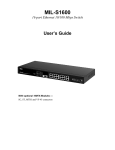
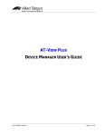
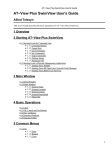
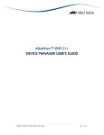
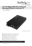
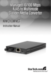
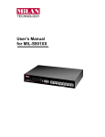
MIL-SM801xx
Managed 9 Port Switch
Eight 10/100BASE-TX Ethernet ports
With
One fixed 100BASE-FX port
USER GUIDE
Regulatory Approval
- FCC Class A
- UL 1950
- CSA C22.2 No. 950
- EN60950
- CE
- EN55022 Class A
- EN55024
Canadian EMI Notice
This Class A digital apparatus meets all the requirements of the Canadian Interference-Causing Equipment Regulations.
Cet appareil numerique de la classe A respecte toutes les exigences du Reglement sur le materiel brouilleur du Canada.
European Notice
Products with the CE Marking comply with both the EMC Directive (89/336/EEC) and the Low Voltage Directive
(73/23/EEC) issued by the Commission of the European Community Compliance with these directives imply conformity to
the following European Norms:
-
EN55022 (CISPR 22) - Radio Frequency Interference
EN61000-X - Electromagnetic Immunity
EN60950 (IEC950) - Product Safety
Five-Year Limited Warranty
MiLAN Technology warrants to the original consumer or purchaser that each of it's products, and
all components thereof, will be free from defects in material and/or workmanship for a
period of five years from the original factory shipment date. Any warranty hereunder is
extended to the original consumer or purchaser and is not assignable.
MiLAN Technology makes no express or implied warranties including, but not limited to, any
implied warranty of merchantability or fitness for a particular purpose, except as expressly set
forth in this warranty. In no event shall MiLAN Technology be liable for incidental or
consequential damages, costs, or expenses arising out of or in connection with the
performance of the product delivered hereunder. MiLAN Technology will in no case cover damages
arising out of the product being used in a negligent fashion or manner.
Trademarks
© 2000 MiLAN, the MiLAN logo and MiLAN Technology are either trademarks or registered
trademarks of Digi International, Inc. in the United States and/or other countries. All other
trademarks are the property of their respective holders.
To Contact MiLAN Technology
For prompt response when calling for service information, have the following information ready:
- Product serial number and revision
- Date of purchase
- Vendor or place of purchase
You can reach MiLAN Technology technical support at:
E-mail: [email protected]
Telephone: +1.408.744.2751
Fax: +1.408.744.2771
MiLAN Technology
1299 Orleans Drive
Sunnyvale, CA 94089-1138
United States of America
Telephone: +1.408.744.2775
Fax: +1.408.744.2793
http://www.milan.com
info @ milan.com
© Copyright 2001 MiLAN Technology P/N: 90000374_B
Contents
1. Introduction…….…………….…………….……….……………………
1
Features ……………………………………………………....…..…….……..
Intelligent Management Features ……………………....…………………..
Package Contents ………………………..………………..……….………...
Ethernet Switching Technology ………………………..…………………….
Management Methods ………………………………….……...……………..
2
2
2
3
4
2. Hardware Description ………………..….…...…...…………………….
5
Front Panel ……………………………..……………………...…...…………..
MIL-SM801 ………………………………………………………………………
MIL-SM801SC with SC Connector …………….………………...………….
MIL-SM801ST with ST Connector ………………………………..…………..
MIL-SM801MT with MT-RJ Connector ………..…………………..………….
MIL-SM801VF with VF-45 Connector …………………………..…………….
LED Indicators ………………………………………………………………….
Rear Panel ……………………………………………..……………………….
Desktop Installation ……………………….………………….……..………….
5
5
5
6
6
6
6
7
8
3. Network Configuration …………..…….…….…….…………………….
9
Connecting a Terminal or PC to the Console Port …………..….....………..
Assigning IP address ……………...………….………..………....……………
Secured IP ……………………….…..………………………………………….
Resetting Factory Defaults ……………...………….………..………....………
4. Web-Based Management .……………………………………………….
System Login ………………………..……………....…………….……..………
5. System Configuration .……………………………………………………
Network Setting…………………………………………….…...………………
System Group…………………………………………….…...…………………
Statistics …………………………………………….…...……………………….
Port Config …………………………………….………...………....……………
Speed Config …………………………………….…...………..……….……….
VLAN ………….……………………………….…...…………….……………. .
Trunking ………………………………………………...…….…....…………….
Agent Config ……………………………………………………………………..
9
10
13
14
15
15
17
17
17
18
19
20
21
23
24
6. Technical Specifications .…………………….....………………………
26
7. Troubleshooting .…………………………………..……………………..
Incorrect connections ...……………………………………………….…………
Diagnosing LED Indicators ………………………..…………………..………..
27
27
27
Appendix Internet Explorer Setting…….……….…………………………
28
1. Introduction
In today’s society, the ability to communicate quickly and share important data is
essential to our lifestyle. Computer networks have proven to be one of the fastest
methods of communication.
The MIL-SM801XX series are compact desktop size switches that are ideal
solutions for small, medium and enterprise networks. The switch provides wirespeed switching with high-performance, and low-cost connections. Using the storeand-forward switching method, this switch can auto-learn and store up to 8K worth
of MAC addresses.
Figure 1-1. The MIL-SM801XX
The MIL-SM801xx switch provides eight-switched auto-sensing 10/100 Mbps RJ-45
Ethernet ports plus one 100Base-FX fiber port. The switch will automatically detect
the speed of the device that you plug into, allowing you to use both 10 and
100Mbps devices. The 10Mbps bandwidth will accommodate 10Mbps workgroup
hubs while simultaneously providing the 100Mbps bandwidth needed to
accommodate multimedia applications. In addition, each RJ-45 port supports Auto
MDI/MDIX for easy installation.
The MIL-SM801XX switch provides one 100Base-FX fiber port. There are 4 types
of fiber connectors available on the switch. These fiber connectors are SC, ST, MTRJ, VF-45 (multi-mode) and SC (single-mode). The fiber port can be used to
connect to a remote site up to 2 kilometers (multi-mode) or 15~60 kilometers (SC
single- mode).
The MIL-SM801XX includes built in Web-based Management. You can easily
configure and monitor the switch through your web browser. You can also use our
text base console program through Telnet, Serial Console, or any SNMP
management system.
1
Features
n
n
n
n
n
n
n
n
n
n
n
n
n
Conforms to IEEE 802.3, 802.3u, and 802.3x Ethernet Standards
Eight auto-sensing 10/100Mbps Ethernet RJ-45 ports
Automatic MDI/MDIX crossover for each 10Base-T/ 100Base-TX port
One fixed 100Mbps fiber port
One RS-232 for Serial Console management
Half-duplex mode for back pressure, and full-duplex for flow control
Store-and-forward switching architecture for abnormal packet filtering
Automatic address learning, address migration
8K-entry MAC address table
512KB memory buffer sharing
Performs non-blocking full wire speed (1.8Gbps)
LED-indicators for Power, 100M, LK/ACT, FD/COL
10-inch desktop size design
Intelligent Management Features
n
n
n
n
n
n
n
n
n
Web-based management
SNMP network management
Console management
Supports nine port based VLAN groups and support for multiple VLANs on a
port
Port Trunking ( Up to 4 ports ---800Mbps cascade )
MIB II ( RFC1213 ) supported
Port Configuration
Port Disable/Enable Setting
Auto-negotiation, 100 Full/half-duplex, or 10 Full/half-duplex mode
Package Contents
n
n
n
n
n
MIL-SM801XX
Power cord
Four rubber feet
RS-232 cable for console port
User Guide
2
Figure 1-2. Package Contents
Compare the contents of your MIL-SM801XX package with the standard checklist
above. If any item is missing or damaged, please contact your local dealer for
service.
Ethernet Switching Technology
Ethernet Switching Technology dramatically boosted the total bandwidth of a
network, eliminated congestion problems inherent with Carrier Sense Multiple
Access with Collision Detection protocol, and greatly reduced unnecessary
transmissions.
Switches have revolutionized the network world in three major ways. First, by using
a switch you can have two-way, simultaneous transmissions over the same port (full
duplex), essentially doubling the bandwidth. Second, by reducing the collision
domain to a single switched-port “Carrier Sensing” is eliminated. Third, using storeand-forward switching, unnecessary transmissions can be eliminated to avoid
congestion.
Auto-negotiation regulates the speed and duplex of each port, based on the
capability of both devices. Flow-control allows transmission from a 100Mbps node
to a 10Mbps node without loss of data. You may need to disable auto-negotiation
and flow control for some networking operations involving legacy equipment.
Disabling the auto-negotiation is accomplished by fixing the speed or duplex of a
port.
3
Management Methods
The MIL-SM801XX series supports the following management methods:
n
n
n
Console and Telnet Management
Web-based Management
SNMP Network Management
Console and Telnet Management
Console Management is done through the serial Console Port. This method
requires a direct connection between a PC and the MIL-SM801XX. Telnet
management is done over the network. Once the MIL-S801XX has an assigned IP
address and is on the network, you can use Telnet to login and make configuration
changes.
Web-based Management
The switch provides an embedded HTML web site residing in flash memory. It offers
advanced management features and allows users to manage the MIL-SM801XX
from anywhere on the network through a standard browser such as Microsoft
Internet Explorer or Netscape Navigator. For more information, see chapter 6.
SNMP Network Management
SNMP (Simple Network Management Protocol) provides a way to monitor and
control network devices, and to manage configurations, statistic collection,
performance, and security.
4
2. Hardware Description
This section describes the hardware of the MIL-SM801XX series. The switch is compact
in size with eight auto-sensing 10/100Mbps Ethernet RJ-45 ports and one 100Base-FX
fiber port.
Front Panel
The front panel of the MIL-SM801XX series consists of eight auto-sensing 10/100Mbps
Ethernet RJ-45 ports (automatic MDI/MDIX), one 100Base-FX fiber port, and LED
indicators.
Different front panels of the MIL-SM801XX series are illustrated below. There are four
different types of fiber connectors available for the convenience of your connectivity.
These fiber connectors are SC, (SC single-mode), ST, MT-RJ and VF-45.
Figure 2-3. The Front Panel of the MIL-SM801XX with SC (single mode) connector
Figure 2-4. The Front Panel of the MIL-SM801XX with ST connector
5
Figure 2-5. The Front Panel of the MIL-SM801XX with MT-RJ connector
Figure 2-6. The Front Panel of the MIL-SM801XX with VF-45 connector
n
RJ-45 Ports (Auto MDI/MDIX): Eight 10/100 auto-sensing for 10Base-T or
100Base-TX connections. MDI configuration provides the means to connect to
another hub or switch while MDIX provides connection to a workstation or PC.
n
100Base-FX Fiber Port: There are four connectors available for the MILSM801XX as shown above. The distance for multi-mode fiber cabling can be
up to 2 kilometers, whereas the distance for SC single-mode fiber can be up to
60 kilometers.
LED Indicators
Figure 2-7. Detail of LED Indicators
There are three LED-indicators (100M, LNK/ACT, FDX/COL) for each UTP port.
The following table provides descriptions of the LED indicators. They provide a realtime indication of operational status.
6
LED
Power
Status
Color
Description
On
Green
Power On
On
Green
The port is operating at the speed of 100Mbps
100M
Off
On
LNK /
ACT
Blinks
Off
On
FDX /
COL
Blinks
Off
In 10Mbps mode or no device attached
Green The port is successfully connected to a device
Green The port is receiving or transmitting data
No device attached
Amber The port is operating in full-duplex mode
Amber Collisions are occurring on the port
Half-duplex mode or no device attached
Table 2-1. Description of LED Indicators
Rear Panel
The 3-pronged power plug is located at the rear panel of the MIL-SM801XX as
shown in Figure 2-8. The switch will work with AC in the range of 100-240V AC, 5060Hz.
Figure 2-8 The Rear Panel of the MIL-SM801XX
7
Desktop Installation
Set the switch on a sufficiently large flat space with a power outlet nearby. The
surface should be clean, smooth, level, and sturdy. Make sure there is enough
clearance around the switch to allow for air circulation and the attachment of cables
and power cord.
Attaching Rubber Feet
A. Make sure mounting surface on the bottom of the switch is grease and dust
free.
B. Remove adhesive backing from the rubber feet.
C. Apply the rubber feet to each corner on the bottom of the switch. These
footpads can protect the switch from shock/vibration.
Figure 2-9. Attaching rubber feet to the bottom of the switch
8
3. Network Configuration
This section explains how to configure console management using the console
management program.
Console management involves the administration of the switch via a direct
connection to the RS-232 console port, which has a female DB-9 connector. From
the main menu of the console program, user has access to manage the functions of
the switch.
Connecting a Terminal or PC to the Console Port
Figure 3-1. Connecting the MIL-SM801XX to a terminal via RS-232 cable
Use the supplied RS-232 cable to connect a terminal or PC to the console port. The
terminal or PC to be connected must support the terminal emulation program.
After connecting the switch via the RS-232 cable, run a terminal emulation
program or Hyper Terminal to match the following default characteristics of the
console port:
Baud Rate: 9600 bps
Data Bits: 8
Parity: none
Stop Bit: 1
Control flow: None
Figure 3-2.
The settings of communication
parameters
9
Note: Console program is case sensitive.
After you have finished setting parameters, press the “Enter” Key and the Main
Menu of console management appears.
Figure 3-3. The Main Menu of Console Management
Assigning an IP Address to the switch
Once you have logged into the MIL-SM801XX, you need to assign an IP address to
the switch’s Ethernet interface so that you can connect to the switch using a Web
Browser.
1.
From the Main Menu of the console, select Item 1 by typing in “1” after the
prompt and press Enter. You must select the appropriate Boot Method --Flash, BOOTP, or DHCP (For more information, see Web-based Management
– Agent Config ).
2.
There are three command options to change the IP Address (the initial Default
IP address is 192.168.1.77). For example, if you wanted to change the IP
address to 199.86.12.40, you could type one of the following at the MIL
prompt:
MIL> ip-address 199.86.12.40
MIL> 2 199.86.12.40
MIL> ip 199.86.12.40
Note: After typing in the command press Enter twice.
10
3.
You will now find that the default IP address has been changed to IP address
192.168.12.40. Reboot by typing “reboot” or “H”.
4.
By similar methods, you can configure Subnet Mask (default subnet Mask is
255.255.255.0), Broadcast (default Broadcast is 255.255.255.255), and
Gateway (default Gateway is 192.168.1.6). The gateway address is the router
that can forward packets to the other IP networks.
Figure 3-4. Changing IP address by typing in “ ip-address 199.86.12.40 ” after the prompt .
11
Figure 4-5. Execute reboot
Figure 3-6. After pressing Enter twice, you will find the old IP address has changed into new
IP address.
Note: After any setting changes, reboot. Use the ping command for verification.
12
Secured IP
Secured IP can guard against unauthorized users accessing the switch
management. Network security for IP access allows only one IP address or up to 3
IP addresses to access the web based management server and telnet server.
The Default Secured IP is 0.0.0.0 for all three secured IP, which means that no
network security on IP was set from original factory setting. Now, if you want to set
Secured IP, for example, you can type in “securedip 1 199.86.12.46” after the
prompt press Enter twice. The first Secured IP has been registered. Only the end
station with IP 192.168.1.27 has access to the network management.
Figure 3-7. Type in “ securedip 1 199.86.12.46” after the prompt in order to set the first
secured IP.
13
Figure 3-8. After pressing Enter twice, the first secured IP address is set to 199.86.12.46.
Resetting Factory Defaults
You can reset the switch back to factory default settings by using the loaddefault
command. Simply type L 2 at the MIL>_ prompt and press enter.
Note: If you do not type L 2, and only type L, the following option appears:
Usage: loaddefault (0:1:2).
The only correct option is L 2 for the MIL-SM801XX.
14
4. Web-Based Management
This section introduces the configuration and functions of the Web-based management
for the MIL-SM801XX series.
The MIL-SM801XX series provides an embedded HTML website residing in flash
memory. It offers management features and allows users to manage the MILSM801XX from anywhere on the network through a standard Web Browser.
System Login
1. Start browser.
2. Type in the IP Address of MIL-SM801XX after “http://
button.
3. The following Welcome Screen appears.
Figure 4-1. The Welcome Screen
15
“. Then press Enter
4. Click Login button, then the Password Dialog Box appears.
Figure 4-2. The Password Dialogue Box
5. Type in your User Name and Password.
(the default is “root” for both.)
6. Click the “OK” button
16
System Configuration
After you have started the Web-Based Management you can begin to configure
the system.
Click System from the Main Menu to display the following screen:
Figure 5-1. The System Page
The System Page displays information about the MIL-SM801XX.
Network Setting
IP address: 199.86.12.40
Subnet Mask: 255.255.255.0
Broadcast: 255.255.255.255
Default gateway: 0.0.0.0
System Group
SysUp Time: MIL-SM801XX uptime.
SysContact: You can enter the name of the person to contact if there are problems
with the MIL-SM801XX switch.
SysName : You can enter a name for the MIL-SM801XX.
17
SysLocation: You can enter the switch physical location.
Example: “MiLAN BLDG 10”
Statistics
The Statistics page displays detailed information for each port.
Figure 5-2. The Statistics Page
Note: Java must be enabled for statistics information to display. See Appendix
settings.
18
Port Configuration
You can use the Port Configuration Page to Disable / Enable ports.
Figure 5-3. The Port Config Page. In Figure 5-3, the default of each port is Enable.
To Disable / Enable any port:
1. Select the drop-down menu in the Status Column.
2. Choose the status you want for each Ethernet or Fiber port.
3. Click Apply button to activate settings selected.
19
Speed Config
In the Speed Configuration Page, you can configure the speed and duplex of
each port.
Fig. 5-4. The Speed Config Page
To select the speed parameters for a port:
1. Select the drop-down menu in Speed/Duplex Column.
2. Select one of the following 6 Items: Auto/flow control enabled, Auto/flow control
disabled, 100Base-Tx/Full Duplex, 100Base-Tx/Half Duplex, 10Base-T/Full
Duplex, 10Base-T/Half Duplex.
3. Click Apply.
20
VLANS
A LAN was originally defined as a network of computers located within the same
area.. Today, LANs are defined as a single broadcast domain. This means that if a
user broadcasts information on his/her LAN, every user on the LAN will receive the
broadcast. A VLAN (Virtual LAN) is a group of ports designated by the switch as
belonging to the same broadcast domain. This feature allows workgroups to be
defined on the basis of their logical location instead of their physical location.
VLANs can be used to strengthen security between the departments as well as
isolating broadcast traffic to increase net bandwidth.
Figure 5-5. The example of VLAN setting on VLAN Page
Each port can be configured to belong to one or more of the nine VLANs by clicking
on the desired group(s). By default, all ports are a member of one group. A port
can be a member of more than one group.
21
Trunking
Trunking allows you to create additional bandwidth by aggregating several ports
into one single group.
Figure 5-6. The Trunking Page
From the Trunking page you can click the drop-down menu and select your desired
trunk group. You have a choice between a 2-port trunk (ports 1&2) or 4-port trunk
(ports 1, 2, 3, & 4).
Remember to click Apply after making your selection.
Note: Make sure Trunking ports are in the same VLAN group.
22
Agent Config
After clicking the Agent Configuration page, the screen displays the MILSM801XX’s current configuration. Refer to the following Agent Configuration page
for your own settings.
Figure 5-7. The Agent Config Page
23
Boot Methods
There are three modes that you can boot your switch in --FLASH Boot – Boots from a memory chip that software images can be stored,
booted, and rewritten as necessary. Flash memory resides in a chip and holds its
content without power.
BootP - Boots your system from a BootP (Bootstrap Protocol) server. BootP is a
TCP/IP protocol used by a diskless workstation or network computer to obtain its IP
address and other network information such as server address and default
gateway.
DHCP Boot – Boots your system from a DHCP (Dynamic Host Configuration
Protocol) server. DHCP servers can automatically assign IP addresses to client
stations logging onto a TCP/IP network.
The following are the initial factory values. You can change the information by
entering new information. (For example, you can change the MIL-SM801XX’s IP
address by directly typing in new IP address.) Then click Apply after entering the
information.
Boot-Method: flash
IP address: 193.31.103.7 (192.168.1.77)
Submask: 255.255.255.0
Broadcast: 255.255.255.255
Gateway: 192.168.1.6
Trap1: 0.0.0.0
Trap2: 0.0.0.0
Trap3: 0.0.0.0
Trap4: 0.0.0.0
GetCommunity: public
SetCommunity: public
TrapCommunity: public
Telnet/HTTP-Username: root
Telnet/HTTP-Password: root
Secured_IP1: 0.0.0.0
Secured_IP2: 0.0.0.0
Secured_IP3: 0.0.0.0
Remember to click the Reboot Agent button for changes to take effect.
Note: SNMP traps are only sent after a cold start.
24
6. Technical Specifications
The following table lists the specifications of the MIL-SM801XX series.
Specifications
Standards Compliance IEEE 802.3 10Base-T Ethernet,
IEEE 802.3u 100Base-TX/FX Fast Ethernet
ANSI/IEEE 802.3 Auto-negotiation
Protocol
CSMA/CD
Max Forwarding and
14,880 pps per Ethernet port
148,800 pps per Fast Ethernet port
Max Filtering Rate
LED Indicators
Per Port: (10/100 UTP ): 100M, LK/ACT, FD/COL ( 3 LEDs )
Fiber Port: 100M, LK/ACT, FD/COL ( 3 LEDs )
Per Unit: Power
Copper Network
10Base-T: 2-pair UTP/STP Cat. 3, 4, 5 cable
Cables
EIA/TIA-568 100-ohm ( 100m )
100Base-TX: 2-pair UTP/STP Cat. 5 cable
EIA/TIA-568 100-ohm ( 100m )
Fiber Link Max.
ST/SC/MT-RJ/VF-45 Multi-mode:
Distance
Half-duplex: 412m, Full-duplex: 2Km
SC Single-mode:
Half-duplex: 412m, Full-duplex: 15~60Km
Dimensions
250mm x 132mm x 37mm (9.8” x 5.2” x 1.5”)
1080 ±20 g 2.4lbs
Weight
Storage Temp.
Operational Temp.
Operational Humidity
External Power
Power Consumption
EMI
-40ºC to 70ºC ( -40ºF to 158ºF)
0ºC to 45ºC ( 32ºF to 113ºF )
10% to 90% (Non-condensing)
100-240V AC, 50-60Hz
17 Watts ( Max )
FCC Class A, CE Mark
Safety
UL, cUL
25
7. Troubleshooting
This section is intended to help you resolve the most common problems on the MILSM801XX series.
Incorrect connections
n
Faulty or loose cables
Look for loose or obviously faulty connections. Make sure the connections are
snug. If that does not correct the problem, try a different cable.
n
Non-standard cables
Non-standard or incorrectly pinned cables may cause anything from network
collisions to no network connectivity at all. A category 5 cable tester is
recommended during your network installation.
n
Improper Network Topologies
It is important to make sure that you have a valid network topology. Common
topology faults include excessive cable length and too many repeaters (hubs)
between end nodes. In addition, you should make sure that your network topology
contains no data path loops. Between any two-end nodes, there should be only one
active cabling path at any time. Data path loops will cause broadcast storms that
will severely impact your network performance.
Diagnosing LED Indicators
You can diagnose common problems by monitoring the LED indicators on the front
panel of the switch. If you are having network connection issues the first place to
check is the switches LED link lights. If you do not have a link light, you may have
an incorrect cable type.
If the power LED does not light up when the power cord is plugged in, you may
have a problem with power outlet, or power cord.
n Cabling
RJ-45 ports - Use unshielded twisted-pair (UTP) or shield twisted-pair (STP) cable
for the RJ-45 connections. Use 100ohms Category 3, 4 or 5 cable for 10Mbps
connections or 100ohms Category 5 cable for 100Mbps connections. Also be sure
that the length of any twisted-pair connection does not exceed 100 meters (328
feet).
100Base-FX fiber port - Fiber multi-mode connector type must use 50/125 or
62.5/125µ multi-mode fiber cable. You can connect two devices up to 2-kilometers.
With single-mode fiber use 9/125µ fiber cable for multi-mode as well. You can
connect two devices from 15 to ~60- kilometers in full duplex operation.
26
Appendix
Browser Settings
In order to view all fields when using the MIL-SM801XX Web-based Management with
Microsoft’s Internet Explorer you must modify the browser's Java settings. The screen
shots from Internet Explorer 5.0 will aid you in making the necessary changes.
Open up Internet properties.
Go to Start>Settings>Control panel and double click on Internet Options
Step 1: Select the “Security”
tab
Step 2:
Select ” trusted sites ”
Step 3 : Enter the assigned IP
address of the MIL-SM801xx
to the zone, then click " Add "
27
Step 4: Un-check left-bottom box –
“Require server verification for all sites this
zone”, then click "OK"
Step 5: Go back to Internet
Options, then click “ Custom
Level ”
27
Step 6: Select “ Custom ”
under “Java ”
28
Step 7: Select: Java - “Custom”
Step 8: Select “Edit Permissions” then
“Enable” under
”Run Unsigned Content”, then click "OK".
29
90000374_B