1
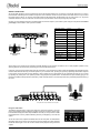
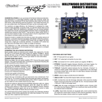
www.radialeng.com
True to the Music
SW8 MK2
™
Eight Channel Auto-Switcher
Part No. R800 8100 00
User Guide
Radial Engineering Ltd.
1588 Kebet Way, Port Coquitlam BC V3C 5M5
tel: 604-942-1001 • fax: 604-942-1010
email: [email protected] • web: www.radialeng.com
www.radialeng.com
SW8™ MK2 Auto-Switcher User Guide
Combination Eight Channel Auto Switcher &
Transformer Isolated Direct Box
Table of Contents
Page
SW8 Overview .........................................................1
Features and Functions ...........................................2
Getting Started ........................................................3
Making Connections ................................................4
Remote Switching....................................................5
Auto-Switching.........................................................6
Linking SW8 Units Together ....................................7
Reconfiguring XLR Outputs .....................................8
Grounding Options ..................................................8
Signal Flow Block Diagram......................................9
Specifications ..........................................................9
Warranty .................................................Back Cover
INTRODUCTION
Congratulations on your purchase of a Radial SW8™ Auto-Switcher. The SW8 is designed to provide
redundant backup for a multi-track playback system and is equally functional as part of a safety backup
system to switch announcements or other messaging. This manual covers the setup and operation of
the SW8 in a typical concert setting. Please take a few minutes to read through this manual in order to
familiarize yourself with the many innovative features incorporated into the SW8. Inside you will find
important safety features along with tips on how to get the most out of your SW8.
Should you have any questions on an application not covered in this manual, we invite you to log onto
the Radial web site at radialeng.com to check the SW8’s FAQ section for the latest updates. This is also
where we post questions from users. If after this you still do not find what you are looking for, feel free to
send us an email at [email protected] and we will do our best to reply in short order.
Now get ready to seamlessly switch backing tracks with total confidence!
!
PERFORMANCE DISCLAIMER
The Radial SW8 is an electronic device designed to provide the means to backup other electronic
devices. However, like all electronics, the SW8 itself is not totally immune to malfunction.
Because the SW8 is designed to integrate with other devices to form a complete system, a
critical malfunction may not be obvious until the system is asked to perform. This makes it very
important to test your complete playback system before each performance to ensure your system
is working as expected.
Radial Engineering Ltd. will not be held liable for any consequential or inconsequential costs
or damages associated with the use of the SW8. It is understood that connecting, testing and
operating the SW8, along with the application or misapplication, is the sole responsibility of the
end user. For more details refer to the Radial limited warranty.
OVERVIEW
The Radial SW8 is an eight channel redundant switcher designed primarily for live concerts where backing tracks are used to reinforce
the performance. Should the primary playback machine suffer a failure, the SW8 can switch to a backup machine either automatically,
manually, or by remote control.
The SW8 lets you select between two groups of eight audio inputs and route either group to eight discrete outputs. Input connections are
made with your choice of standard eight channel 25-pin D-Sub connectors or individual ¼” TRS phone jacks for easy interface with a variety
of audio playback systems. Choice of outputs include an eight channel balanced line-level 25-pin D-Sub or eight transformer isolated miclevel XLR outputs. Most system techs employ the D-Sub output to feed their personal payback system for monitoring and use the front
panel XLR outputs to connect to the mic splitter and snake system for the PA.
PRIMARY-A
MULTI-TRACK
BACKUP-B
MULTI-TRACK
®
CONTROL MONITOR
PAD
AUTO
MUTE
THRESHOLD
GLOBAL
ON
STANDBY
INPUT SELECT
A
B
ALARM
LIFT
LIFT
LIFT
LIFT
LIFT
LIFT
LIFT
LIFT
PIN-1
PIN-1
PIN-1
PIN-1
PIN-1
PIN-1
PIN-1
PIN-1
TONE
BELOW
THRESHOLD
8-CH AUTO
BACK-UP
SWITCHER
A TONE B
SOUND REINFORCEMENT
SYSTEM
PLAYBACK SYSTEM
CONTROL
The SW8 can operate in three modes; manual, remote and auto-switch. Depending on your personal preference, experience and confidence
with your setup, you will likely choose one of these approaches and stick with it. Some techs prefer a hands-on approach where they run
two computers completely separately so that should one fail, the other is autonomous. They will typically start both laptops at the same time
and then manually switch between them if a problem is encountered. Others prefer to automate the process whereby they will lock both
devices together with time code. Should the master playback system fail the SW8 will automatically switch to the backup.
Manual switching is accomplished using the front panel AB select switch. In situations where the SW8 may be remotely stationed, a remote
switch may be connected. This can be done using a simple latching footswitch such as the type used on a guitar amp to change channels
or turn on a reverb, or by using the optional Radial JR2 remote. This dual-function footswitch gives you control over AB select and standby
functions along with LED status indicators. When set to auto-switch mode, the SW8 can detect a machine malfunction and switch to a
backup player to ensure a seamless performance. You merely record a 1kHz tone onto the primary recorder (drone track) and send the
signal into the SW8’s auto-switch gate input on the rear panel. As soon as the drone track disappears, the SW8 diverts the inputs to the
backup system. For larger playback system requirements, several SW8 units may be linked together to create 16, 24 or 32 track systems.
You simply designate the first SW8 as a master unit and link as many slaves as you like using the JR2 link jacks.
The Radial SW8 has gained international notoriety as is used on stage every day with artists as diverse as U2, Lady Gaga, The Eagles,
Radiohead and Cirque Du Soleil.
Radial Engineering Ltd.
1
SW8™ MK2 User Guide
FEATURES AND FUNCTIONS
Front Panel
1.
GLOBAL PAD: Attenuates the signal going to the XLR direct box
outputs by -20dB to prevent transformer saturation.
5.
STANDBY: Holds the auto-switching on inputs-A so that the
SW8 does not switch to inputs-B while waiting for drone signal.
2.
AUTO ON: Activates the auto-switching mode. When active
it monitors the gate input (channels 1, 8 or direct) for a drone
signal and switches from inputs-A to inputs-B if the signal
disappears.
6.
A-B SELECT: Front panel selector used to manually switch from
inputs-A to inputs-B.
7.
ALARM LED: Illuminates when the drone signal falls below the
set threshold level.
3.
THRESHOLD: Sets the gate input sensitivity. If the drone signal
drops below the set threshold the SW8 will switch from inputs-A
to inputs-B. Two level sensing LED’s illuminate when signal is
detected.
8.
XLR OUT: Balanced, low-Z mic-level direct box outputs connect
to the PA system and are transformer isolated to help eliminate
hum and buzz caused by ground loops.
4.
MUTE: Turns off the balanced XLR outputs, leaving the
balanced D-Sub output on for local monitoring.
9.
LIFT: Disconnects pin-1 on the XLR output to further assist in
reducing noise caused by ground loops.
10. LABEL STRIP: Easy to read, wax pencil label strip for channel
identification and assigment.
®
CONTROL MONITOR
PAD
AUTO
MUTE
STANDBY
GLOBAL
1
ON
A TONE B
2
3
INPUT SELECT
A
THRESHOLD
4
5
B
6
ALARM
LIFT
LIFT
LIFT
LIFT
LIFT
LIFT
LIFT
LIFT
PIN-1
PIN-1
PIN-1
PIN-1
PIN-1
PIN-1
PIN-1
PIN-1
TONE
BELOW
THRESHOLD
10
9
8
7
24
11
12
13
8-CH AUTO
BACK-UP
SWITCHER
14
15
16
23
17
18
19
20 21
22
Rear Panel
11. TRS ¼” INPUTS-A & B: Two sets of eight balanced or unbalanced
line-level inputs for your primary and backup multi-track units.
12. D-Sub OUTPUT: Balanced line-level output is used to send the
active input set (A or B) to the PA or local monitor system.
13. D-Sub INPUTS: Balanced line-level A and B inputs are used to
connect two multi-track playback units to the SW8.
14. ALT 1/8: Selects between channel 1 or channel 8 to receive the
drone track for auto-switching.
15. FILTER: Lets you use a binary audio signal such as SMPTE
time code as a drone track by smoothing out the signal for better
detection.
16. AUTO-SWITCH GATE INPUT and MONITOR OUTPUT: The ¼”
TRS input lets you connect directly to the auto-switching gate.
Used as an alternate to channels 1 or 8, so that all eight channels
are available for playback tracks. The ¼” monitor output lets you
listen to the drone track to ensure it is being received.
20. CONTACT ALARM: Tip-sleeve ¼” connection from an internal
relay can turn on a siren or beacon when the drone signal
drops below the set threshold.
21. CONTACT INPUT: Tip-sleeve ¼” latching contact closure is
used to switch the SW8 with a remote footswitch or contact.
22. 15 VDC SUPPLY: Provides power to the SW8. Handy cable lock
ensures supply will not be accidentaly disconnected.
Top Panel Switches
23. REMOTE LINK OUTPUT MODE: Used when linking the
SW8mk2 to an older SW8(mk1) through ¼” LINK-OUT jack.
24. STANDBY SWITCH CONTROL MODE: Assigns the standby
function to either the local front panel switch or the MUTE
footswitch on the optional JR2.
17. ON A/B (JR2 FOOTSWITCH): Turns on remote A/B switching
when using the optional JR2 footswitch and disables the front
panel A/B select switch.
18. JR2 FOOTSWITCH XLR: Connection for the optional JR2
remote footswitch. Lets you remotely switch between A & B
inputs and engage the standby mode.
23
24
19. JR2-IN and LINK-OUT: ¼” TRS input may be used with the JR2
instead of the XLR. Also used to link multiple SW8’s together for
larger 16 and 24 channel playback systems.
Radial Engineering Ltd.
2
SW8™ MK2 User Guide
GETTING STARTED
The following considers you will be using the SW8 to switch between two eight channel multi-track machines running in sync and designated
as the PRIMARY-A and the BACKUP-B playback systems. The SW8 lets you instantly switch from the PRIMARY-A to the BACKUP-B
system and outputs eight isolated channels to the PA system and eight direct channels for local monitoring. If you anticipate switching
manually you can fill all eight tracks of your multi-track with audio. If you plan to use the auto-switch function, you will need to record a tone
or drone track onto one of the channels. This is explained in detail later in the manual.
PRIMARY-A
MULTI-TRACK
BACKUP-B
MULTI-TRACK
®
CONTROL MONITOR
PAD
AUTO
GLOBAL
ON
MUTE
THRESHOLD
STANDBY
INPUT SELECT
A
B
ALARM
LIFT
LIFT
LIFT
LIFT
LIFT
LIFT
LIFT
LIFT
PIN-1
PIN-1
PIN-1
PIN-1
PIN-1
PIN-1
PIN-1
PIN-1
TONE
BELOW
THRESHOLD
8-CH AUTO
BACK-UP
SWITCHER
A TONE B
PLAYBACK SYSTEM
(DIRECT OUT)
PA SYSTEM
(ISOLATED OUT)
Audio inputs
You can connect your two playback recorders to the SW8 using either ¼” TRS connectors or 25-Pin D-Subs. The balanced TRS connectors
are wired to the AES standard with tip (+), ring (-) and sleeve (ground) and the D-Sub is wired following the Tascam / ProTools 8-channel
standard. You can find the pin wiring diagram at the back of the manual or on the rear panel of the SW8. Both the ¼” TRS and the 25-pin
D-Sub inputs are internaly wired in parallel and work with balanced or unbalanced sources.
BACKUP-B
MULTI-TRACK
PRIMARY-A
MULTI-TRACK
BACKUP-B
MULTI-TRACK
PRIMARY-A
MULTI-TRACK
Primary and backup multi-tracks connected to the TRS inputs.
Primary and backup multi-tracks connected to the D-Sub inputs.
Audio Outputs
The SW8 is equipped with both a 25-pin D-Sub output on the rear panel and eight XLR-male outputs on the front panel. The D-Sub is a
balanced 8-channel output that is coupled directly to the input relays while each XLR output is configured like a passive direct box with an
isolation transformer, a -20dB PAD and a ground lift switch. An internal jumper cable can be reconfigured so that the transformer isolated DI
outputs may be routed to the 25 pin D-Sub output. Most playback system technicians employ the direct D-Sub output to feed their personal
playback system for pre-fader-listening, cueing and monitoring while using the isolated XLR outputs to connect to the PA. As the PA
system’s mixing console is often far removed, transformer isolating these outputs helps eliminate hum and buzz caused by ground loops.
®
CONTROL MONITOR
PAD
AUTO
GLOBAL
ON
MUTE
THRESHOLD
STANDBY
INPUT SELECT
A
B
ALARM
LIFT
LIFT
LIFT
LIFT
LIFT
LIFT
LIFT
LIFT
PIN-1
PIN-1
PIN-1
PIN-1
PIN-1
PIN-1
PIN-1
PIN-1
TONE
BELOW
THRESHOLD
8-CH AUTO
BACK-UP
SWITCHER
A TONE B
SOUND REINFORCEMENT
SYSTEM
PRIMARY-A
MULTI-TRACK
PLAYBACK SYSTEM
CONTROL
BACKUP-B
MULTI-TRACK
Front XLR outputs connect to PA system. Rear D-Sub output connected to local monitoring station.
Radial Engineering Ltd.
3
SW8™ MK2 User Guide
MAKING CONNECTIONS
As with all audio equipment, ensure system levels are turned off before making any connections. This will help avoid turn-on or plug-in
transients that could damage more sensitive components such as tweeters. There is no power switch on the SW8. As soon as you connect
the power supply, it will turn on and one of the LED’s below the AB select switch will illuminate to let you know power is on. To prevent
accidental disconnect, there is a cable lock next to the power input jack that is used to loop-through the power cable.
Connect your two playback machines to the SW8 inputs and send the output to your monitor system using the rear panel D-Sub. Before
you hit play... set the SW8 in ‘start-up mode’ as follows:
PRIMARY-A
MULTI-TRACK
PLAYBACK SYSTEM
CONTROL
BACKUP-B
MULTI-TRACK
FUNCTION - FRONT
STATUS
LED
PAD
OFF
OFF
AUTO
OFF
OFF
THRESHOLD
12 O’CLOCK
OFF
MUTE
OFF
OFF
STANDBY
OFF
OFF
AB SELECT
A
ON
LIFT (X8)
OFF
FUNCTION - REAR
STATUS
ALT CHANNEL 1/8
CHANNEL 1
FILTER
OFF
JR2-ON
OFF
FUNCTION - TOP
STATUS
POSITION
OUT
CENTER
OUT
REMOTE LINK
SW8-MK2
STANDBY
LOCAL
TOWARDS
FRONT
BACK
Always test at a low volume as this will reduce possible damage due to improper connections. Turn on both playback systems and try
switching between inputs A and B by depressing the front panel AB select switch.
If all is well, connect the XLR-male outputs from the front panel to your main PA mixer. These outputs are isolated to help eliminate the hum
and buzz that often find their way into audio systems. If you encounter noise, try lifting the ground by depressing the lift switch adjacent
to each output. In the event that you hear distortion, check to make sure your signal levels are not overloading the input on your console
by adjusting the preamp trim. If the problem persists, simply depress the global PAD on the SW8 and the input sensitivity going to the
transformer isolated XLR outputs will be reduced by -20dB. The PAD switch is recessed to prevent being accidentally depressed during a
live show.
®
CONTROL MONITOR
PAD
AUTO
MUTE
THRESHOLD
GLOBAL
ON
STANDBY
INPUT SELECT
A
B
ALARM
LIFT
LIFT
LIFT
LIFT
LIFT
LIFT
LIFT
LIFT
PIN-1
PIN-1
PIN-1
PIN-1
PIN-1
PIN-1
PIN-1
PIN-1
TONE
BELOW
THRESHOLD
8-CH AUTO
BACK-UP
SWITCHER
SOUND REINFORCEMENT
SYSTEM
A TONE B
Front panel XLR outputs feed the main PA system.
Using the mute switch
The SW8 is equipped with a mute function that turns off the XLR outputs on the front
panel. This innovative feature enables the playback technician to mute the outputs going
to the PA while leaving the D-Sub output unaffected. This lets you cue up tracks or make
level adjustments ‘on the fly’ without disturbing what may be happening in the main PA
system.
CONTROL MONITOR
MUTE
D
STANDBY
INPUT SELECT
A
B
ALARM
TONE
BELOW
THRESHOLD
To use the mute function, depress the MUTE switch on the front panel. An LED indicator
illuminates when the function is active to alert you the XLR outputs are muted. Depress
the MUTE switch again to turn the function off and restore playback through the XLR
outputs.
Radial Engineering Ltd.
4
SW8™ MK2 User Guide
SWITCHING THE SW8 VIA A REMOTE
It is sometimes preferable to have the playback recorders and SW8 located in a secondary rack off to the side. A common example would
be a keyboard player that is also managing the playback system. To address these situations, the SW8 may be remotely switched using a
common latching footswitch.
The rear panel is equipped with a ¼” CONTACT INPUT jack that will cause the SW8 to switch by merely shorting the tip of the ¼” connector
to ground. Switching can be performed using a typical guitar amp latching footswitch such as the type used to switch channels or turn on a
reverb. You can also cause the SW8 to change inputs using a simple toggle switch or by connecting a contact closure from a MIDI system.
PRIMARY-A
MULTI-TRACK
LATCHING
FOOTSWITCH
PLAYBACK SYSTEM
CONTROL
BACKUP-B
MULTI-TRACK
Using the JR2 Remote
The optional Radial JR2 is a compact footswitch that is equipped with two foot-activated switches, accompanying LED indicators and choice
of XLR or ¼” TRS output connectors. This multipurpose footswitch is unique in that it derives its power from the device that is connected –
which in this case is the SW8. The right footswitch is labelled A/B and the left hand switch is labeled mute. When used with the SW8, the
A/B footswitch switches the SW8 between A and B inputs. The JR2 mute switch actually sets the SW8 into standby mode which is discussed
later in this manual. Simply plug the JR2 into the SW8 using a standard XLR mic cable and turn on the JR2 function by depressing the ON
A/B switch. Test by depressing the right hand A-B footswitch. The LED indicators will follow to let you know the status.
STANDBY (MUTE): Holds
auto-switching on inputs-A
while playback is paused.
A-B SELECT: Used to
remotely switch from
inputs-A to inputs-B.
PRIMARY-A
MULTI-TRACK
JR2 FOOTSWITCH
CONTROL
PLAYBACK SYSTEM
CONTROL
BACKUP-B
MULTI-TRACK
Using the 24V alarm output
In certain situations, creating some sort of visual or audible alarm may be needed. For instance, lighting a beacon or sounding a buzzer can
notify the audio engineer of a problem. Another example may be when using the SW8 as part of an evacuation system to sound an alarm.
The SW8 is equipped with a special 24 volt relay that is designed for this purpose. The relay is connected to an external circuit and power
supply using a standard ¼” jack on the rear panel as illustrated below..
Normally, the relay is in an ‘open’ state preventing current from flowing through the external circuit. If the drone signal feeding the AUTOGATE input falls below the set THRESHOLD level, the relay closes allowing current to flow through the external alarm circuit and the front
panel ALARM LED illuminates. When the drone track is restored the relay opens and the alarm turns off.
Radial Engineering Ltd.
5
SW8™ MK2 User Guide
AUTO-SWITCHING
To use the SW8 in the auto-switch mode, record a drone track (steady state tone) onto your primary playback recorder. This channel is then
connected to the SW8’s gate input where the signal is detected. If the drone signal ‘drops out’ the SW8 will divert the 8 inputs from primary-A
playback system to the backup-B system using a series of relays. A pure 1kHz tone is recommended but any steady state tone will work
for the drone track. You merely need to adjust the threshold to match the level. You can monitor the drone track using the gate monitor out.
This can also be used to loop through for other units should you wish to have several units switch concurrently via a ‘drone and gate’ setup.
DRONE
TRACK
Alternate Input
Channels 1 or 8
®
Auto-switch Gate
Direct Input
CONTROL MON
AUTO
MUTE
STANDBY
ON
INPUT SE
A
THRESHOLD
A TONE B
Threshold control sets the sensitivity
of the auto-switch detector
PRIMARY-A
MULTI-TRACK
LOCAL MONITOR AND
SYNC CONTROL
Connect the drone track to channels 1 or 8 using the
D-Sub or ¼” inputs or connect direct to the gate input.
BACKUP-B
MULTI-TRACK
In fact you can even use or SMPTE time code as an audio source. Digital square wave carrier signals can be smoothed out using the
3-position filter on the rear panel to have it ‘look’ more like a sine wave. Simply test using the various filter and threshold settings to find the
one that produces stable results.
Auto-switch gate input
The auto-switch gate that controls automatic switching is arranged so that it can be fed from three different source inputs:
1.
Channel-1, Input-A: Diverts to the auto-gate input automatically unless a cable is connected to the gate input.
Make sure the 1/8 ALT switch is in the out position to connect channel-1 to the auto-switch gate.
2.
Channel-8, Input-A: Many techs prefer to record the drone on channel-8 as it leaves 1 free as a primary
playback channel. Simply depress the ALT 1/8 switch inward to route channel-8 to the auto-switch gate.
3.
Direct to gate: You can also patch a signal directly to the auto-switch gate by connecting to the gate input. This
defeats the channel-1/8 routing option, leaving these channels free for more playback channels.
The ¼” gate input features a switching jack that defeats the channels 1 or 8 routing when a plug is inserted.
In other words, channels 1 or 8 are routed to the gate input unless a plug is inserted into the ¼” gate input.
Using the auto-switch function
Turn auto-switching on by depressing the front panel AUTO switch inward. An LED illuminates to
alert you the auto-switch mode is active. This will disengage the A/B select switch on the front panel
along with the remote JR2 and contact closure switching functions. Rotate the THRESHOLD level
control fully counter-clockwise. Start your primary (A) machine with the drone track. The SW8’s
LED below the A/B switch will indicate signal is present. Adjust the threshold clockwise until the
SW8 switches from B to A. To test, pause the A playback system and the SW8 will switch to B.
Activate your B playback rig to audition the two sources as you switch back and forth using the
threshold control.
AUTO
THRESHOLD
ON
Using the standby function
One of the cool new features on the SW8 is the addition of a STANDBY switch. This is used to
arm the SW8 so that it is not searching for a drone signal when one may not be present. For
instance, consider a situation where a song finishes, and the artist decides to talk to the audience
between songs. The playback technician immediately reaches over and stops the main playback
unit which in turn will shut off the drone signal. This in turn will cause the SW8 to switch to the B
backup playback system as it assumes that there is a system fault. The standby switch enables the
playback technician to pause playback and hold the SW8 on it’s primary ‘A’ inputs as he awaits the
count-in for the next song. As soon as the song begins, he starts the backing tracks to follow the
band. He can then leisurely revert back to auto-mode by turning the standby switch off allowing the
SW8 to monitor the drone signal.
The standby mode can be activated in two ways, via the front panel STANDBY switch or by remote
control via the optional JR2 footswitch. The standby control mode switch on the top cover allows
you to choose LOCAL control via the front panel switch or REMOTE control.
Radial Engineering Ltd.
6
A TONE B
Set the THRESHOLD control to 7
o’clock and turn clockwise until the
SW8 switches to the inputs-A.
Use the STANDBY CONTROL MODE switch
to choose between local or remote control.
SW8™ MK2 User Guide
LINKING MULTIPLE SW8 SWITCHERS TOGETHER
For larger playback rigs, the SW8 may be configured in a master-slave configuration whereby two link connectors are used to tie multiple
SW8’s together. Once connected these jacks relay front panel A/B switching and provide the same remote control capabilities as the
optional JR2 footswitch. For instance, one footswitch connected to the master can control multiple SW8’s and in doing so, also sends the
‘standby’ command to the slave units. This lets you build 16, 24, 32 or even 64 channel playback rigs and have all audio channels switch
from A to B at the same time. To set up a link, make sure the REMOTE LINK mode switch on the top panel is set accordingly (see below).
Connect a standard ¼” TRS cable from the master SW8 JR2 LINK-OUT to the slave’s ¼” TRS JR2 LINK-IN connectors. For larger systems,
continue the chain from the first slave to the second and so on.
BACKUP-B (1~8)
MULTI-TRACK
TRACKS 1~8
SYNC
PRIMARY-A (1~8)
MULTI-TRACK
MASTER SW8MK2
DRONE
TRACK
SYNC
BACKUP-B (9~16)
MULTI-TRACK
SYNC
TRACKS 9~16
SLAVE SW8MK2
TRACKS 17~24
SYNC
PRIMARY-A (9~16)
MULTI-TRACK
SLAVE SW8MK2
BACKUP-B (17~24)
MULTI-TRACK
PRIMARY-A (17~24)
MULTI-TRACK
When combining two SW8 MK2 (second generation) units together, make sure the LINK-MODE switch on the top panel is set to the SW8
MK2 position. When combining your second generation SW8 MK2 with a first generation SW8 MK1, the switch needs to be set to the SW8
MK1 position. This ensures that both units switch in proper sync.
REMOTE LINK switch set
for an MK2 slave unit.
Radial Engineering Ltd.
REMOTE LINK switch set
for an MK1 slave unit.
MASTER SW8 (MK2)
MASTER SW8 (MK2)
SLAVE SW8 (MK2)
SLAVE SW8 (MK1)
7
SW8™ MK2 User Guide
RECONFIGURING THE ISOLATED OUTPUTS WITH THE INTERNAL RIBBON CONNECTOR
An internal ribbon cable allows the SW8 to be reconfigured so that the eight transformer isolated mic-level outputs appear on the rear panel
25 pin D-Sub connector. This allows mic-level connections to be made at the rear panel instead of the front XLR jacks. The -20dB PAD, the
LIFT switches and the front panel XLR outputs will continue to function as normal.
To reconfigure the internal ribbon cable, remove the top panel and locate the D-Sub output ribbon cable. Gently remove the ribbon
connector from the circuit board and plug it into CONN4 XLR OUT on the circuit board as shown below. The red stripe on the ribbon cable
should be on the same side as the rear panel and the notch on the connector should match with the notch silk screened on the circuit board.
CONN4
XLR OUTS
D-SUB OUTPUT
RIBBON CABLE
Shown in the default configuration with a
direct line-level D-Sub output.
Notch
Shown in the alternate configuration with an
isolated mic-level D-Sub output
INTERNAL CHASSIS GROUND LIFT
All connectors are 100% isolated, allowing chassis and signal grounds to be kept separate. However, an internal switch for each channel
is provided to connect the pin-1 cable shields to the chassis without modifying the SW8. By default, this switch is factory set to open or
‘lifted’ allowing the chassis to ‘float’ ungrounded. Should a specific grounding scheme require the cable shields to be bonded to the chassis,
remove the top cover and set the eight switches to the closed (pushed in) position. The switch may be accessed by removing the top cover.
CHASSIS
GROUND 8
CHASSIS
GROUND 1-7
Radial Engineering Ltd.
8
SW8™ MK2 User Guide
BLOCK DIAGRAM
PRIMARY-A
¼” TRS INPUTS
PRIMARY-A
D-Sub INPUTS
PAD
ISO
XLR
MUTE
XLR OUTPUT
A/B
SWITCHING
CONTROL
BACKUP-B
D-Sub INPUTS
D-Sub OUTPUT
BACKUP-B
¼” TRS INPUTS
SPECIFICATIONS
FEMALE DB-25 PIN-OUT (PANEL VIEW)
Input-A & B
1/4” phone: ..................TRS balanced +4dB / -10dB
D-Sub: .........................DB25 balanced +4dB / -10dB
Input impedance: ........140K ohms typical (without Global PAD)
10k ohms typical (with Global PAD)
13
G
G
1+
+
2-
G
G
3+
+
4-
G
G
5+
+
6-
G
G
7+
+
81
MALE DB-25 PIN-OUT (CABLE VIEW)
6
+
-
+ 7G
-
G
-
4
+5G
+3G
2
G
-
13
+1G
American standard SAE
lock-down screws.
+
-
!
Foot-SW
1/4” phone: ..................Contact closure to ground
Contact Relay
1/4” phone: ..................5-24 VDC relay circuit
G
+
-
-
G
+
8
-
XLR Output
Frequency response: ...20Hz to 20kHz +/- 2.5dB
THD: ............................0.01 % from 20Hz to 20kHz
Output impedance: ......600 ohms
Output: .........................-50dB (mic level) balanced (pin-2 hot)
PAD: ............................-20dB ( Global - all channels)
2
3
Direct Output
Type: ............................Passive balanced signal path
Switching Time: ...........3ms maximum @ 20°C
XLR OUTPUTS
Ground
Positive (
Dimensions: .................19” x 6.5” x 1.75” (1RU)
482.6mm x 165.1mm x 44.45mm
Weight: ........................7.2 lbs. (3.26 kg.)
Power supply: ..............Output 15 VDC @ 400 mA
1
+)
2
3
-
Negative ( )
¼” TRS INPUTS
-
Negative ( )
Ground
Radial Engineering Ltd.
9
Positive (
+)
SW8™ MK2 User Guide
RADIAL ENGINEERING LTD. (“Radial”) warrants this product to be free from defects in
material and workmanship and will remedy any such defects free of charge according to the
terms of this warranty. Radial will repair or replace (at its option) any defective component(s)
of this product (excluding finish and wear and tear on components under normal use) for
a period of three (3) years from the original date of purchase. In the event that a particular
product is no longer available, Radial reserves the right to replace the product with a similar
product of equal or greater value. In the unlikely event that a defect is uncovered, please
call 604-942-1001 or email [email protected] to obtain an RA number (Return Authorization number) before the 3 year warranty period expires. The product must be returned
prepaid in the original shipping container (or equivalent) to Radial or to an authorized Radial
repair center and you must assume the risk of loss or damage. A copy of the original invoice
showing date of purchase and the dealer name must accompany any request for work to be
performed under this limited and transferable warranty. This warranty shall not apply if the
product has been damaged due to abuse, misuse, misapplication, accident or as a result of
service or modification by any other than an authorized Radial repair center.
THERE ARE NO EXPRESSED WARRANTIES OTHER THAN THOSE ON THE FACE
HEREOF AND DESCRIBED ABOVE. NO WARRANTIES WHETHER EXPRESSED OR
IMPLIED, INCLUDING BUT NOT LIMITED TO, ANY IMPLIED WARRANTIES OF MERCHANTABILITY OR FITNESS FOR A PARTICULAR PURPOSE SHALL EXTEND BEYOND
THE RESPECTIVE WARRANTY PERIOD DESCRIBED ABOVE OF THREE YEARS. RADIAL SHALL NOT BE RESPONSIBLE OR LIABLE FOR ANY SPECIAL, INCIDENTAL OR
CONSEQUENTIAL DAMAGES OR LOSS ARISING FROM THE USE OF THIS PRODUCT.
THIS WARRANTY GIVES YOU SPECIFIC LEGAL RIGHTS, AND YOU MAY ALSO HAVE
OTHER RIGHTS, WHICH MAY VARY DEPENDING ON WHERE YOU LIVE AND WHERE
THE PRODUCT WAS PURCHASED.
Radial Engineering Ltd.
1588 Kebet Way, Port Coquitlam BC V3C 5M5
tel: 604-942-1001 • fax: 604-942-1010
email: [email protected] • web: www.radialeng.com
Radial SW8 MK2 User Guide - Part #R870 1192 00
Specifications and appearance are subject to change without notice.
Copyright 2013 © All rights reserved.
www.radialeng.com
RADIAL ENGINEERING LTD.
3 YEAR TRANSFERABLE LIMITED WARRANTY