1
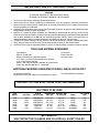
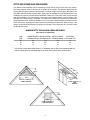
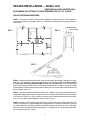
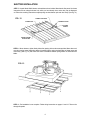
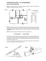
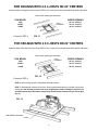
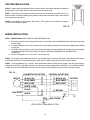
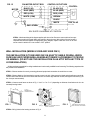
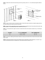
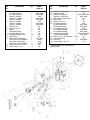
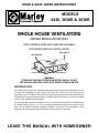
READ & SAVE THESE INSTRUCTIONS
MODELS
2438, 3038R & 3638R
WHOLE HOUSE VENTILATORS
CEILING INSTALLATION ONLY
NOTE: MODELS 3038R AND 3638R ARE AVAILABLE
FOR CEILING AND WALL INSTALLATION.
HOT AIR OUT
HOT AIR OUT
COOL AIR IN
COOL AIR IN
WARNING:
TO REDUCE THE RISK OF FIRE OR ELECTRIC SHOCK, DO NOT
USE THIS FAN WITH ANY SOLID-STATE SPEED CONTROL DEVICE.
INTRODUCTION
Your Whole House Ventilator is designed and engineered to provide years of satisfactory service
in cooling and ventilating your entire house. Hot, humid air is drawn from the living areas and
replaced by cooler outside air. This cooler air may be routed through selected areas of the house
by opening the proper windows and doors. A 3-speed control is supplied. A 12-hour timer, Model
1012A, is also available as an accessory.
The recommended method of installation for 16” O.C. joist construction with the 30” Whole House
fan, Model 3038R, (see pp. 3, 4, 5 & 6) completely eliminates all framing and cutting of ceiling
joists, thus providing the easiest installation available. The shutter for this installation is also
designed to give an attractive flush appearance without cutting the center joist.
LEAVE THIS MANUAL WITH HOMEOWNER.
IMPORTANT SAFETY INSTRUCTIONS
WARNING:
TO REDUCE THE RISK OF FIRE, ELECTRICAL SHOCK
OR INJURY TO PERSONS, OBSERVE THE FOLLOWING:
1. Do not use this fan with any Solid-State Speed Control Device.
2. Use this unit only in the manner intended by the manufacturer. If you have questions, contact the manufacturer.
3. Before servicing or cleaning this unit, switch power off at service panel and lock service panel to prevent power
from being switched on accidentally.
4. Installation work and electrical wiring must be done by qualified person(s) in accordance with all applicable codes
and standards, including fire-rated construction.
5. Sufficient air is needed for proper combustion and exhausting of gases through flue (chimney) of fuel burning
equipment to prevent back drafting. Follow the heating equipment manufacturer’s guideline and safety standards
such as those published by the National Fire Protection Association (NFPA), and the American Society for
Heating Refrigeration and Air Conditioning Engineers (ASHRAE), and the local code authorities.
6. CAUTION: For general ventilation use only! Do not use to exhaust hazardous or explosive materials and vapors.
7. When cutting or drilling into wall or ceiling, Do Not damage electrical wiring or other hidden utilities.
8. CAUTION: This unit has an unguarded impeller. Do not use in locations readily accessible to people or animals.
TOOLS AND MATERIALS REQUIRED
Tape Measure
Saber or Circular Saw
Electrical Connectors & Supplies as required
2 x 6 and/or 2 x 4 Wood Framing Materials are required
2 x 2 Furring Strips as required
Shutter - See text under Specific Installation for proper shutter
Power Tools should display the U.L. Listing Mark
Screw Driver
Electric hand Drill
Hammer & Nails
ADDITIONAL MATERIALS REQUIRED FOR WALL INSTALLATION ONLY
3/4” Plywood as required.
Wood Screws, Bolts, Nuts, Washers, Lock Washers as required.
Door Case Molding or Equivalent
CAUTION: CUTTING ROOF TRUSS IS NOT RECOMMENDED.
SHUTTERS TO BE USED
FAN
MODEL
SHUTTER
2438
3038R
3038R
3638R
3038R
3638R
3224
3230
A3024
3236
3130
3136
TYPE OF
OPENING FOR OVERALL SIZE
INSTALLATION
SHUTTER
OF SHUTTER
HORIZONTAL
HORIZONTAL
HORIZONTAL
HORIZONTAL
VERTICAL
VERTICAL
24” x 24”
30” X 30”
301⁄2” X 331⁄2”
36” X 36”
30” X 30”
36” X 36”
26” x 26”
32” X 32”
32” X 36”
38” X 38”
331⁄8” X 331⁄8”
391⁄4” X 391⁄4”
FINISH
CUT CEILING
JOIST
WHITE
WHITE
WHITE
WHITE
ALUMINUM
ALUMINUM
YES
YES
NO
YES
N/A
N/A
BE CAREFUL!
USE PROTECTIVE GLASSES AND FOLLOW ALL SAFETY RULES.
1
ATTIC AIR INTAKE AND DISCHARGE
Your Whole House Ventilator will be discharging a large volume of air into the attic every minute.
Provisions must be made to allow this air to escape to the outside. The sketches below illustrate
several different types of exhaust vents that are in common usage. Of these types, the under-eave
and gable methods are the most prevalent. Under-eave is probably the most satisfactory from the
standpoint of simplicity and economical installation. Make sure under-eave vents are not blocked
with ceiling insulation. The fan requires a given amount of exhaust outlet in order to ensure quiet
operation and unrestricted air movement. The table below shows the minimum area required for
proper operation of fan. Sufficient ventilation is very important. Unless enough is provided, the fan
motor will run hot, activating the thermal protector and shutting off the motor. When it cools, it will
restart. Such intermittent operation is usually an indication of too little outlet air or too little intake
air through the house.
MINIMUM ATTIC DISCHARGE AREAS REQUIRED
(All areas are in square feet)
FAN
SIZE
UNRESTRICTED* WOOD LOUVRE* METAL LOUVRE*
SHUTTERS
OPENING REQD. OPENING REQD. OPENING REQD. AUTO. MAN. ETC.
24”
30”
36”
6.5
9.2
12
14.7
20.7
27
11.4
16
21
4
6.3
9
*If fly screen is used, double these values. If 1/2” hardware cloth or large mesh expanded metal are
used, the values given are sufficiently large. If no screen used, reduce values shown by 20%.
B (Ft.)
B (Ft.)
A (Ft.)
A (Ft.)
(1/2 A X B = AREA Sq. Ft.)
GABLE EXHAUST
(A X B = AREA Sq. Ft.)
EAVE
EXHAUST
B (Ft.)
A (Ft.)
(A X B = AREA Sq. Ft.)
GABLE EXHAUST
2
CEILING INSTALLATION — MODEL 3038
USED WITH AN A3024 SHUTTER ONLY
NO FRAMING OR CUTTING OF JOISTS REQUIRED FOR 16” O.C. JOISTS.
FAN LOCATION AND MOUNTING
STEP 1 - Fan should be located in center of house, preferably in hallway or corridor. This will allow air to
be drawn from all parts of living space. (See Fig. 1). Determine tentative location of fan and proceed as
shown below.
OVERLAP AREA
FIG. 1
FIG. 2
PILOT HOLES
FAN
RS
TE
AF
R
OF
RO
FIG. 3
18” MIN.
CLEARANCE
STEP 2 - Determine joist direction and locate center joist in tentative fan opening. Lightly pencil a rectangular 301⁄2” x 331⁄2” opening on ceiling below where shutter is to be located, or 301⁄2” x 34” when opening
is used to pass fan housing (FAN HOUSING 34” X 34” X 6”) into attic. Make sure the longer side is
parallel to joist direction. Check to be sure that enough clearance area is available on ceiling for overlap
of shutter flanges. Drill two small pilot holes close to center joist, (one on either side) to indicate where hole
will be centered. (See Fig. 2.)
STEP 3 - Now clear insulation and find pilot holes in attic. Tentatively lay out same rectangular holes on
ceiling below. Adjust location of hole if necessary to ensure a minimum vertical clearance from roof rafters
of 18” above fan. (See Fig. 3.) There must be a minimum of 301/4” between the three joists and a maximum of 311/4” to allow proper installation of shutter. (See Fig. 4 & 5.)
STEP 4 - Carefully cut hole in ceiling, being careful not to cut into center joists. Cut along both sides of the
center joist, leaving the 11⁄2” (approximately) strip of ceiling sheet rock covering the center joist. If you have
2 x 4 joist construction, the joists on which the fan will be mounted must be built up to 2 x 6 joist height.
This can be done very easily at this point by nailing (3) 2 x 2 furring strips 40” long to the top of the joists,
one on each joist. (See Fig. 4 thru 7.)
3
FOR CEILINGS WITH JOISTS ON 16” CENTERS
MODEL A3024 SHUTTER
2 X 2 X 40
FILLERS
FIG. 4
EXISTING
2 X 6 JOISTS
(DO NOT CUT!)
FIG. 5
EXISTING
2 X 4 JOISTS
(DO NOT CUT!)
FOR CEILINGS WITH JOISTS ON 24” CENTERS
MODEL A3024 SHUTTER
2 X 6 FRAMING
2 X 6 FRAMING
2 X 2 X 40
FILLER
FIG. 6
EXISTING
2 X 4 JOISTS
(DO NOT CUT!)
FIG. 7
STEP 5A - If the access opening into the attic is not large enough for the fan to pass through, the fan may
be disassembled and lifted into the attic through the shutter hole which has just been cut. (See Step 2,
Page 3.) Disassemble the fan by removing the four bolts holding the channels to the housing as shown
in Fig. 8. The motor-blade assembly should be handled very carefully so as not to bend the fan blade. It
is not necessary to remove the fan blade in order to lift the motor-blade assembly between the joists. (See
Fig.
9.)
However, for an installer working alone, handling the parts will be more difficult, and therefore it may be
desirable to remove the fan blade to prevent damage. To remove the blade, loosen the two set screws in
the hub and slip the blade off. To reassemble the blade once the fan is in the attic, align the two set screws
with the flat on the shaft. Make sure the fan blade hub is flush with the end of the motor shaft and then
tighten both set screws securely (150 in-lbs recommended).
4
EXISTING
2 X 6 JOISTS
(DO NOT CUT!)
In attic reassemble channels and housing with the original bolts and lockwashers. Tighten these bolts
securely.
FIG. 8
FIG. 9
STEP 5B - With fan in attic remove adhesive backing from 1/2” x 1/2” gasket material and attach to the
two bottom flanges of fan which will rest on the joists. (Fig. 10.) Install grommet in bracket (Fig. 10) and
attach on each end of fan, using two of the short screws provided. Position fan over opening so that grommets are resting against center joist. Attach fan and brackets to center joist with the two long wood screws
and flat washers. Do not crush grommet when tightening screws.
GROMMET
FIG. 10
BRACKET
FIG. 11
GASKET
STEP 6 - Attach side panels to fan as shown using remaining short screws and washers. (See Fig. 11.)
Bottom panels should rest upon ceiling. Bend flaps on ends of panels back when inserting panels between
joists. These flaps will then spring back to seal off any space between panel and joist.
5
SHUTTER INSTALLATION
STEP 7 - Unpack Model A3024 shutter and read instructions included. Note that the first part of the shutter
instructions refer to cutting the shutter hole, which you have already done, and so they may be disregarded. Follow the remaining instructions to adjust springs so that shutters open and close freely. (See Fig. 12.)
FIG. 12
SPRING ATTACHED
CONNECTOR
SPRING HOLDER
LOCKING
SCREW
SPRING SHOWN
UNATTACHED
STEP 8 - Mount shutter to joists directly below fan opening with wood screws provided. Note sheet rock
must be covering center joist before shutter is installed. Again, make sure both sides of shutter open and
close freely. (See Fig. 13.) Also make sure there is clearance between spring holder on shutter and fan
blade.
FIG. 13
STEP 9 - Fan installation is not complete. Follow wiring instructions on pages 11 and 12. Test-run fan
through all speeds.
6
CEILING INSTALLATION — ALL OTHER MODELS
FAN LOCATION & MOUNTING
STEP 1 - Fan should be located in center of house, preferably in hallway or corridor. This will allow air to
be drawn from all parts of living space. (See Fig. 1.)
FIG. 1
FIG. 2
OVERLAP AREA
PILOT HOLE
FAN
STEP 2 - Lightly mark a square opening on ceiling (with pencil) where shutter is to be located. Select opening size from chart below on Page 1. Check to be sure at least 1 1/2 inches of clearance area is available
on all sides for overlap of shutter flanges. (See Fig. 2.) Drill a small pilot hole in the center of this square
through ceiling.
STEP 3 - Determine ceiling joist size and spacing; the most common types are:
2 x 4 on 16” centers
2 x 4 on 24” centers
2 x 6 on 16” centers
2 x 6 on 24” centers
Now find pilot hole in attic, and tentatively lay out same square hole as on ceiling below. Adjust location of
this hole so as to cut as few ceiling joists as possible and to ensure a minimum vertical clearance from
roof rafters of 18” above fan. (See Fig. 3.) See installation drawings and specific instructions for your ceiling configuration on page 8, 9 & 10.
To make cuts through joists, use either a saber saw or circular saw. Carefully finish cut with hand saw or
chisel, so that ceiling below is not damaged. (See Fig. 4.)
FIG. 3
FIG. 4
OF
RO
S
ER
FT
RA
18” MIN.
CLEARANCE
7
FOR CEILINGS WITH 2 X 4
JOISTS ON 16” CENTERS
MODEL 2438
FIG. 5
2X6
FRAMING
Determine which ceiling joists are to be cut per STEPS 2 & 3.
Locate your fan size below and follow specific instructions.
MODEL 3038R WITH MODEL 3230 SHUTTER
2X2
FILLER
2X6
FRAMING
Cut ceiling joists to allow 2 x 6 frame box with 24
3/4” x 24 3/4” inside opening.
MODEL 3638R
FIG. 6
2X6
FRAMING
Cut ceiling joists (as shown) to allow 2 x 6 frame box
with 30 3/4” x 30 3/4” inside opening. Add 2 x 2 filler
to each side.
Proceed to STEP 4.
FIG. 7
Cut ceiling joists to allow 2 x 6 frame box with 36
3/4” x 36 3/4” inside opening.
FOR CEILINGS WITH 2 X 6
JOISTS ON 16” CENTERS
MODEL 2438
2X6
FRAMING
Determine which ceiling joists are to be cut per STEPS 2 & 3.
Locate your fan size below and follow specific instructions.
FIG. 8
MODEL 3038R WITH MODEL 3230 SHUTTER
2X6
FRAMING
MODEL 3638R
Cut ceiling joists to allow 2 x 6 frame box with 24
3/4” x 24 3/4” inside opening.
2X6
FRAMING
FIG. 9
Cut ceiling joists to allow 2 x 6 frame box with 30
3/4” x 30 3/4” inside opening.
FIG. 10
Proceed to STEP 4.
Cut ceiling joists to allow 2 x 6 frame box with 36
3/4” x 36 3/4” inside opening.
8
FOR CEILINGS WITH 2 X 4 JOISTS ON 24” CENTERS
Determine which ceiling joists are to be cut per STEPS 2 & 3. Locate your fan size below and follow specific instructions.
Frame inside opening per chart below.
FAN MODEL
INSIDE OPENING
2438
3038R*
3638R
2X6
FRAMING
Proceed to STEP 4.
24 3/4” X 24 3/4”
30 3/4” X 30 3/4”
36 3/4” X 36 3/4”
FIG. 11
FOR CEILINGS WITH 2 X 6 JOISTS ON 24” CENTERS
Determine which ceiling joists are to be cut per STEPS 2 & 3. Locate your fan size below and follow specific instructions.
Frame inside opening per chart below.
2X6
FRAMING
FAN MODEL
2438
3038R*
3638R
INSIDE OPENING
24 3/4” X 24 3/4”
30 3/4” X 30 3/4”
36 3/4” X 36 3/4”
FIG. 12
Proceed to STEP 4.
STEP 4 - Now carefully cut hole in ceiling flush with inside of frame.
STEP 5 - Attach gasket to bottom of fan frame. Be sure gasket seals opening on all sides. Set fan over
opening. It is not necessary to anchor fan as its weight keeps it in place. Nailing fan in place is not
recommended because this tends to transmit any vibration to the framework of your house. (See
Fig. 13.)
FIG. 13
* With Model 3230 Shutter
GASKET
9
SHUTTER INSTALLATION
STEP 6 - Unpack shutter and read instructions included. Carefully follow these instructions to adjust the
spring tension on your shutter. Make sure the shutter opens and closes freely.
STEP 7 - Insert shutter into opening from below and secure with wood screws provided. See Fig. 16.
Make sure there is clearance between spring holder on shutter and the fan blade. Again, make sure that
shutter opens and closes freely.
STEP 8 - Fan installation is now complete. With control in “OFF” position, turn on 120V power supply to
fan. Test run fan through all speeds.
FIG. 16
WIRING INSTRUCTIONS
STEP 1 - PRECAUTIONS: READ CAREFULLY BEFORE WIRING FAN !
A. Electrical connections and all wiring should be done in accordance with the National Electrical Code and all local codes
that may apply.
B. To avoid possibility of serious injury or electrical shock, the installer must disconnect electric circuit supplying power PRIOR
to wiring fan.
C. CAUTION: Incorrect wiring can cause motor failure and possible fire. Marley Engineered Products will not accept liability
for damage resulting from incorrect wiring. FOLLOW ALL WIRING DIAGRAMS AND ALL INSTRUCTIONS
CAREFULLY.
D. This fan is designed to run on 120 volt A.C., 60 Hz power only.
STEP 2 - The 3-speed control packed with this fan is used to operate fan from a remote wall location. Generally the best location is
in the hallway near the fan. The control should be in sight of the fan. Install a single switch box at the location chosen.
STEP 3 - The wiring diagrams, Figs. 14 and 15, show two alternate methods of wiring fan and control. If the 120V power supply is
available at the FAN, Fig. 14 should be followed. If the 120V power supply is available at the CONTROL, Fig. 15 should be followed.
In either case, note that the BROWN control wire must be connected to the BLACK (hot) wire from the 120V power supply.
FIG. 14
FAN MOTOR OUTLET BOX
MOTOR
120V, 60 HZ
CONTROL OUTLET BOX
BLACK (HI)
BLUE (MED)
RED (LOW)
WHITE (COM)
BLACK (HI)
BLUE (MED)
RED (LOW)
BLACK
BROWN
WHITE
GND. SCREW
120V SUPPLY AVAILABLE AT FAN
10
CONTROL
FAN MOTOR OUTLET BOX
FIG. 15
MOTOR
CONTROL OUTLET BOX
BLACK (HI)
BLUE (MED)
RED (LOW)
WHITE (COM)
BLACK (HI)
BLUE (MED)
RED (LOW)
BROWN
CONTROL
BLACK
120V, 60 HZ
WHITE
GND. SCREW
120V SUPPLY AVAILABLE AT CONTROL
STEP 4 - After determining which diagram applies, pull wires to fan. Be sure to secure cable at fan to prevent it being caught in the blade. Make connections to fan and control. After wiring of fan and control is
completed and checked against the appropriate wiring diagram, replace outlet box cover on fan and
secure control in switch box. Leave control in “OFF” position.
WALL INSTALLATION (MODELS 3038R AND 3638R ONLY)
THIS INSTALLATION IS TO BE USED ONLY IN AN ATTIC GABLE OR WALL WHICH
FACES AN UNOCCUPIED AREA, AN AREA NOT READILY ACCESSIBLE TO PEOPLE
OR ANIMALS. (DO NOT USE THIS INSTALLATION IN AN ATTIC WITH ANY TYPE OF
LOOSE INSULATION.)
All fans are factory assembled for ceiling installation and can be easily modified for wall mounting. The following steps describe
this procedure and installation.
STEP 1—Reverse rotation of motor by reversing yellow and purple lead connections in conduit box on motor.
STEP 2—Remove blade by first loosening the two set screws in the hub. Now reverse the blade and reinstall onto motor shaft.
Hub should be flush with the end of the motor shaft. Be sure set screws align with flats on shaft, then tighten bolt securely (150
lbs. of torque recommended).
STEP 3—Construct wood frame as shown in Fig. 1. Use 2” x 4” or 2” x 6” (depending on thickness of wall where unit is to be
mounted) framing lumber.
“A”
SEE CHART
4” OR 6” —
DEPENDING ON
THICKNESS OF WALL
“B”
SEE
CHART
FIG. 1
FIG. 2
DRILL (4) - 1/4” HOLES - (1) IN CENTER OF EACH
FLANGE AS SHOWN.
STEP 4—Drill (4) holes in fan housing as shown in Fig. 2.
11
FIG. 3
SECURE SHUTTER IN PLACE
WITH WOOD OR LAG SCREWS
STEP 5—Position fan on frame and secure with (4) wood or lag screws (number 12 x 1 1/2” preferred) through holes drilled in
STEP 4.
DOUBLE 2 X 6
HEADER
SECURE UNIT IN PLACE
WITH 2” X 2” FURRING
STRIPS INSIDE.
SEE
CHART
2 X 4 FRAMING
SECURE UNIT IN PLACE
OUTSIDE WITH MOULDING
FIG. 5
FIG. 4
STEP 6—Unpack shutter and read the instructions included. Carefully follow these instructions to adjust the spring tension on
your shutter. Make sure the shutter opens and closes freely.
STEP 7—Stand assembly upright with motor at top and position shutter on outside of frame. Secure shutter with (8) wood or lag
screws (number 12 x 1” preferred) through holes in shutter frame. See Fig. 3.
STEP 8—To mount this attic fan in gable or wall, a box must be framed into wall construction as shown in Fig. 4. See wall opening in chart.
FAN SIZE
30”
36”
“A” & “B” DIMENSIONS
33 3/4” x 33 3/4”
39 3/4” x 39 3/4”
WALL OPENING SIZE
34” x 34”
40” x 40”
STEP 9—Insert frame containing fan and shutter assembly into opening with outside surface of shutter frame flush with outside
surface of wall.
STEP 10—Nail frame assembly securely in place. Moulding may be used outside to improve appearance, as shown in Fig. 5.
Caulk around moulding to provide a water-tight seal. Follow wiring instructions on pages 11 & 12.
12
ACCESSORY CONTROL
MODEL 1012A Timer Switch may be used to control the fan, if it is desirable to run the fan after retiring at night. Time
switch can be set manually to run up to 12 hours, turning fan off automatically at the pre-set time.
OPERATING HINTS AND SUGGESTIONS
1. Never operate your Whole House Ventilator with all outside doors and windows closed. Air will be drawn down
the chimney bringing soot into the house. This could also impair fuel gas ventilation of furnaces, water heaters,
etc. located in the house, possibly drawing fumes into the house. Be sure to open enough doors and windows
to provide adequate ventilating air intake.
2. For best results, open windows in OCCUPIED rooms only. This will ensure maximum breeze where you want it
most. Before retiring at night, bedroom windows may be opened 15-30 minutes earlier in order to give the fan
opportunity to draw out bedroom heat and bring in cooling air from the outside. Windows should be opened 4”6” from the bottom for best results.
3. Experiment with the drawing power of the fan. It is possible, by regulating room doors and windows, to get the air
movement through several rooms without actually opening windows in all the rooms. Air in the house acts like
water in a pipe; it follows the path you provide.
4. DO NOT BECOME ALARMED IF FAN MOTOR FEELS HOT TO THE TOUCH. Its operating temperature is up
to 90 degrees above room temperature — much too hot for your hand to stand comfortably.
MAINTENANCE
1. Turn off all electric power — remove fuse or disconnect circuit breaker — before performing any maintenance!
2. DO NOT ATTEMPT TO LUBRICATE FAN MOTOR WHEN INSTALLED. Re-lubricate per instructions on motor.
3. When shutters are in adjustment, the air stream should open the shutter completely. If this does not occur, see
directions packed with shutter.
4. ALL FAN SHAFT BEARINGS ARE SEALED. They should never require any maintenance.
5. Check belt tension semi-annually for looseness and/or excessive belt wear. See Fig. 17.
FIG. 17
TOO TIGHT
SLIGHT BOW
TOO LOOSE
6. DO NOT OVER-TIGHTEN BELT! After tightening belt, turn control to “LOW” while power supply to fan is still disconnected. While someone watches the fan, turn power on. If fan starts easily on “LOW” belt is not too tight.
7. Check fan periodically for any material such as insulation having fallen into or onto any part of fan.
13
REF.
NO.
1
2
3
4
5*
6
7
8†
9*
10
11
12 *
13 *
DESCRIPTION
33” V-Belt, FHP 4L330
33” V-Belt FHP 4L370
44” V-Belt FHP 4L440
Sheave, 4” OD Motor
Sheave, 3.5” OD Motor
Sheave, 3” OD Motor
Sheave, 5” OD Motor
Sheave, 6” OD Motor
Sheave, 7” OD Motor
Shaft, 0.75” OD
Screw, 1/4-28 x 1/2”
Bearing
Bearing Mount Plage
Set Screw, Blade 5/16”-24
Nut, Serrated Flanged 1/4-20
Washer, Plate
Motor, PSC 1/4 HP 3 Speed
Motor, PSC 1/4 HP 3 Speed/Rev.
Motor, PSC 1/2 HP 3 Speed
Motor, PSC 1/2 HP 3 Speed/Rev
Washer, Flat 5/16” ID 7/8” OD
Screw, 1/4-20 x 1” Hex
QTY.
MODEL
USED ON
1
1
1
1
1
1
1
1
1
1
4
2
2
2
16
2
1
1
1
1
14
12
2438
3038, 3038R
3638, 3638R
2438
3038, 3038R
3638, 3638R
2438
3038, 3038R
3628, 3638R
ALL
ALL
ALL
ALL
ALL
ALL
ALL
2438, 3038
3038R
3638
3638R
ALL
ALL
REF.
NO.
DESCRIPTION
14 * Screw, 10-16 x 1/4” Type B
15 Bracket, Capacitor
16 Capacitor, 10 MFD 370V
Capacitor, 12.5 MFD 370V
17 Boot, Capacitor Terminal Cover
18 Mount, Motor
19 * Washer, Lock 1/4” ID
20 Fan Housing Assembly
Fan Housing Assembly
Fan Housing Assembly
21 24” Fan Blade Assembly
30” Fan Blade Assembly
36” Fan Blade Assembly
22 3 Speed Control Assembly
3 Speed Control Assembly
23 † Gasket, 1/2” x 1/2” Pres. Sensitive
24 Bracket, Reinforcing
25 † Panel, Side
26 Screw, SEMS 1/4-20 x 3/4”
QTY.
2
ALL
1
ALL
1 2438, 3038, 3038R
1
3638, 3638R
1
ALL
1
ALL
8
ALL
1
2438
1
3038, 3038R
1
3638, 3638R
1
2438
1
3038, 3038R
1
3638, 3638R
1 2438, 3038, 3038R
1
3638, 3638R
13.5 LF
ALL
1
ALL
4
3038, 3038R
4
ALL
* Standard Hardware Item, Available Locally
† Item Not Shown
14
MODEL
USED ON
LIMITED WARRANTY
Dear Customer,
Thank you for your interest in Marley Engineered Products products. We’re sure you will
enjoy its benefits for many years to come. Please take a minute to fill out the following
information and keep it in your permanent records.
Date Purchased
Date Installed
Model Number
Serial Number
3.
The Marley Engineered Products Service Representative will determine the best way
to resolve the difficulty.
Products within warranty which have been installed and returned to the seller for repair will
be repaired and returned as used products. Repairs to products outside the warranty period will be subject to labor and parts charges.
LIMITED WARRANTY
This Marley Engineered Products product is warranted to be free of defects in material and
workmanship for 12 months from date of original purchase.
There is no other warranty, express or implied, except such as is expressly set forth herein.
Seller will not be liable for any general, consequential, or incidental damages, including without limitation any damages for loss of use or loss of profits, for any breach of warranty or for
negligence. Seller’s liability and buyer’s exclusive remedy are limited to the repair of defective
goods or the shipment of equivalent goods, or the granting of a reasonable allowance on
account of any defects, as the seller may elect.
To obtain performance under this warranty, you must:
1.
Contact the Marley Engineered Products Service Department at 1-800-642-HEAT
between the hours of 8:00 a.m. and 5:00 p.m. E.S.T. Monday through Friday.
2.
Provide the model number of the product, the date of installation, and state the nature of
the difficulty being experienced.
Some states have enacted legislation which (a) does not allow the inclusion of limitations
on incidental or consequential damages; (b) does not allow limitations on the length of a
warranty period; (c) precludes exclusion, during the period of a limited warranty, of any
implied warranties of merchantability or fitness for purpose.
To the extent of such provisions being applicable in your state, the limitations in this warranty may not apply.
TO ENSURE SAFE OPERATION
• Be sure that this unit is correctly installed and wired by a qualified installer in accordance
with the instructions and applicable NEC or equivalent codes.
• Be sure that operating instructions are followed and that moving and heating parts are
kept clean and free from obstructions.
Any warranties granted or liabilities assumed hereunder will not apply to goods that have
been damaged in transit, altered, repaired, installed or operated otherwise than in conformity with the above requirements for safe operation.
HOW TO ORDER REPAIR PARTS
In order to obtain any needed repair or replacement
parts, warranty service or technical information, please
contact Marley Engineered Products Service Center tollfree by calling 1-800-642-HEAT.
When ordering repair parts, always give the information listed as follows:
1. The Part Number
2. The Model Number
3. The Part Description
4. Date of Manufacture
Part No. 5200-2555-000
SPX Corporation
470 Beauty Spot Rd. East
Bennettsville, SC 29512 USA
PPD 035
4-00