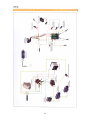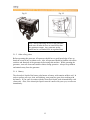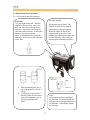
1
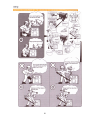
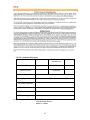
OWNER’S MANUAL
Air-cooled diesel engine generator set
DG4LE / DG6LE
1
PREFACE
Thank you for purchasing products from EASTERN TOOLS & EQUIPMENT, INC. We
appreciate your business. The following manual is only a guide to assist you and is not a
complete or comprehensive manual of all aspects of maintaining and repairing your
generator. The equipment you have purchased is a complex piece of machinery. We
recommend that that you consult with a dealer if you have doubts or concerns as to your
experience or ability to properly maintain or repair your equipment. You will save time
and the inconvenience of having to go back to the store if you choose to write or call us
concerning missing parts, service questions, operating advice, and/or assembly questions.
Our air-cooled diesel generators have some of the following features:
•
•
•
•
•
•
•
•
•
•
Lightweight construction
Air cooled
Four-stroke diesel internal combustion engine
Direct fuel injection system
Recoil starter or an optional electric starter
Large fuel tank
Automatic voltage stabilizer
NFB circuit protector
AC and DC outputs
Low oil pressure sensor
The ETQ air-cooled diesel generators are widely used when electrical power is scarce.
Our generators provide a portable mobile solution in supplying power for field operations
during project construction. Some other known applications include pipeline
construction and metal welding when electrical power is not available.
This manual will explain how to operate and service your generator set.
If you have any questions or suggestions about this manual, please contact your local
dealer or us directly. Consumers should notice that this manual might differ slightly
from the actual product as more improvements are made to our products. Some of the
pictures in this manual may differ slightly from the actual product as well. Eastern
Tools and Equipment, Inc. reserves the right to make changes at any time without
notice and without incurring any obligation.
2
TABLE OF CONTENTS
Overall view of the generator set
Chapter 1 Technical Specifications and Data
1-1 Technical specifications and data
1-2 Basic operating parameters
1-3 General dimensions and overview of the generators
1-4 Electric wiring diagrams for various models of generators
Chapter 2 Operating the Diesel Generator
2-1 Main points of safety during operation of the generator
2-2 Preparation before operation
2-3 Checking the operation of the diesel engine
2-4 Starting the generator set
2-5 Procedures for starting the generator set
2-6 Proper operation of the generator set
2-7 Loading
2-8 Stopping the generator
Chapter 3 Maintenance
3-1 Maintenance schedules
3-2 Storing for long periods of time
Chapter 4 Troubleshooting
4-1 Overhauling and troubleshooting procedures
4-2 Questions and doubts
Chapter 5 Generator Parts Diagrams and Listings
Limited Warranty
Product Registration Card
List for comments from users
Appendix
1. Attached list of tools fittings, and subassemblies
2. Attached technical documents
3
Page number
4
5
5
7
7
8
11
11
13
16
16
19
21
21
23
24
24
26
27
27
27
28
34
34
36
37
37
37
1. Overall view of DG3LE series
3. Overall view of DG6LE series
2. Overall view of DG4LE series
4. Overall view of DG6LE-3P series
4
CHAPTER 1. TECHNICAL SPECIFICATIONS AND DATA
Technical specifications in SI units
Item
Model
3LE Series
Generator
Generator Type
Frequency (Hz)
Rated power (Kw)
Cont. power (kW)
Voltage (AC) (V)
Voltage (AC) (V)
Current (DC) (A)
Speed (rpm)
Power factor (cos ϕ)
Phase type
Number of poles
Excitation
Insulation
Engine model
Type
Diesel Engine
Output Continuous
(kw)
Maximum
(kw)
Bore x Stroke (mm)
Displacement (cc)
60
2.8
2.6
Fuel tank capacity
(L)
Dry weight
Dimensions
(LxWxH) (mm)
60
4.0
3.5
6LE-3P
Series
Three phase
60
6.0
5.5
60
5.0
4.5
120 / 240
12
420/240
8.3
3600
3600
3600
3600
1.0
0.8
Single-phase
2
Self-excitation voltage
B
ETQ170FG
ETQ178FG
ETQ186FG ETQ186FG
Single-cylinder, vertical, 4-stroke, air-cooled, direct
injection
2.98
4.40
6.6
6.6
3.36
4.9
7.34
7.34
70 x 55
78 x 62
86 x 70
86 x 70
219
306
418
418
Forced air cooling by flywheel fan
Lubricating system
Starting system
6LE Series
Single phase AC generator
Cooling system
Lube-oil capacity
4LE Series
Pressure splash, duplex type lubrication
.75
1.1
1.65
1.65
Recoil manual start / Electric start (optional)
15
15
15
15
53
96
119
119
690x470x555 690x470x555 740x500x590 740x500x59
0
5
Technical specifications in English units
Item
Model 3LE Series
Generator
Generator Type
Frequency (Hz)
Rated power (HP)
Cont. power (HP)
Voltage (AC) (V)
Voltage (AC) (V)
Current (DC) (A)
Speed (rpm)
Continuous
(HP)
Maximum
(HP)
Bore x Stroke (in)
Diesel Engine
Outp
ut
Displacement (cu.
in)
Cooling system
Lubricating system
Lube-oil capacity
(oz)
Starting system
Fuel tank capacity
(USgal)
Dry weight (lb)
Dimensions
(LxWxH) (in)
6LE Series
Single phase AC generator
60
3.75
3.49
60
5.36
4.69
3600
12
8.3
3600
60
8.04
7.37
6LE-3P
Series
Three phase
60
6.7
6.04
120 / 240
Power factor (cos
ϕ)
Phase type
Number of poles
Excitation
Insulation
Engine model
Type
4LE Series
420/240
3600
1.0
3600
0.8
Single-phase
2
Self-excitation voltage
B
ETQ170FG ETQ178FG
ETQ186FG
ETQ186FG
Single-cylinder, vertical, 4-stroke, air-cooled, direct
injection
4.0
5.9
8.85
8.85
4.5
6.6
9.85
9.85
2.76 x 2.17
3.01 x 2.44
3.39 x 2.76
3.39 x 2.76
13.36
18.67
25.51
25.51
Forced air cooling by flywheel fan
Pressure splash, duplex type lubrication
25.34
37.17
55.75
55.75
Recoil manual start / Electric start (optional)
3.96
3.96
3.96
3.96
116
27.2x18.5x
21.9
212
263
263
27.2x18.5x21 29.1x19.7x23 29.1x19.7x23
.9
.2
.2
6
1-2 Basic operating parameters
1-1.1 Under the given conditions, the generator will output the specified power in the
table listed below.
Table 1.
Height above sea level (ft)
Ambient temperature (oF)
RH
0
+60 (+20 oC)
60%
<3280.8 (<1000 m)
41~104 (5-40 oC)
90%
1-3 General dimensions and overview of the generators
1-3.1 General dimensions of the LN series generators
7
Wiring diagrams for the LE models
1-4 Electric wiring diagrams for various models of generators
8
9
10
CHAPTER 2 OPERATING THE DIESEL GENERATOR
2-1 General main points of safety during operation of the generator set.
In order to operate the generator set safely, please follow all the instructions provided in
this manual carefully. Doing so otherwise may lead to accidents and or equipment
damage.
2-1.1 Fire prevention
The proper fuel for the diesel generator set is light diesel fuel. Do not use gasoline,
kerosene and or other fuels other than light diesel fuel. Keep all flammable fuels away
from the generator as the generator may spark and ignite these gases. In order to prevent
fires from occurring and to provide enough ventilation for people and the machine, keep
the diesel generator at least 1.5 meters away from buildings and or other equipment.
Always operate your diesel generator on a level site. If the generator is operated on an
incline, the lubricating system within the engine will not perform well and may lead to
failure of the engine.
2-1.2 Prevention from inhaling exhaust gases
Never inhale exhaust gases emitted by the engine. The exhaust gases contain toxic
carbon monoxide. Never operate your generator in places with poor ventilation. In order
to operate this machinery indoors, a suitable ventilation system for the building is
required to draw the poisonous exhaust gases out.
2-1.3 Prevention from accidental burns
Never touch the muffler and its cover when the diesel engine is running. Never touch the
muffler and cover after the diesel engine has been used, as the muffler remains hot for a
good period of time.
2-1.4 Electric shock and short circuits
Never touch the generator if the generator is wet. Also never touch the generator if your
hand is wet. Never operate your generator if the weather conditions call for any type of
precipitation such as rain, snow, or fog. To prevent electrical shocks, the generator
should be grounded. Use a lead to connect the grounding end of the generator to the
grounding surface of choice. Please refer to Fig. 2-1 and Fig. 2-2 before beginning to use
the electric generator.
11
Fig 2-1
Fig 2-2
Note: When connecting devices to the generator,
make sure all other devices are rated lower than
the generators output. Any generator socket
should not be overloaded over its regulated limit
2-1.5 Other safety points
Before operating this generator, all operators should have a good knowledge of how to
break the circuit if any accidents occur. Also, all operators should be familiar with all the
switches and functions of the generator before using this machine. While operating the
generator, wear safe shoes and suitable clothes during operation. Always keep children
and animals away from the generator.
2-1.6 Battery
The electrolytic liquid of the battery also known as battery acid contains sulfuric acid. In
order to protect your eyes, skin, and clothing, wear protective gear when working with
the battery. If you come in contact with the electrolytic liquid, wash it immediately with
clean water. Also, if the electrolytic liquid comes in contact with your eyes, see a doctor
immediately.
12
2-2 Preparation before operation
2-2.1 Fuel choices and fuel treatment
Air filter element
Fuel tank
Use only light diesel fuel. The fuel
should be filtered clean. Never let
dust and water mix with fuel in the
fuel tank. Otherwise it will clog the
fuel lines and oil nozzles. It may also
damage your pressure pump.
Note: It is dangerous to overfill the
fuel tank. Never exceed the red piston
in the filter.
Do not wash the air filter. The
element is made of dry material,
which does not permit washing.
When the output of the diesel
engine is bad or the color of the
exhaust gas is abnormal, replace the
air filter element. Never start the
diesel engine without the air filter.
a. After purchasing fuel, put it
into a drum and let it sit for 34 days.
b. 3-4 days later, insert half of
the fuel sucker into the drum,
(water and impurities stay in
the lower portion of the
drum)
Note:
Never smoke near the opening of
the fuel tank. Do not let sparks get
near the fuel or fuel tank and do not
overfill tank. After filling, tighten
the fuel cap.
13
2-2.2 Filling engine oil
Remove the dipstick from the engine
Make sure the generator is on level
ground, and fill the engine with 15W40
engine oil. Put the dipstick back into the
hole to check the engine oil level.
Engine oil is the most important factor in determining the life of your generator engine.
If you use poor engine oil or if you don’t change the oil regularly, the piston and cylinder
will wear easily or seize up. Also, the life of the other parts in your engine such as
bearings, and other rotating parts will shorten considerably.
Although there is an alarm system to check for low oil pressure, it is always a good idea
to check the amount of oil inside the engine. If the oil level is low, fill it before starting
the engine. A good time to drain the oil from the engine is when the diesel engine is still
hot. If the engine is fully cooled, it is more difficult to drain all the oil out or some
impurities will remain in the engine.
14
2-2.3 Checking the air filter
(1) Loosen the butterfly nut, take the
cover of the air filter off and take
the air filter element out.
(Note: Only certain welder generator sets
have an electric fan incorporated on them.)
Butterfly nut
Before starting the generator, make
sure the air switch is in the “Off”
position. Starting the generator with
the switch in the “On” switch is very
dangerous.
Air filter cover
Do not use detergent to wash the air
filter element. When the
performance of the engine decreases
or when the color of the exhaust
gases is bad, exchange the filter
element. Never start the engine
without the air filter as foreign
objects may enter the intake and
damage the engine.
The generator should be grounded in
order to prevent electric shock.
Use dry compressed air (with
pressure about 1.96 x 10⁵ Pa) to
blow the dust out in the electric
control cabinet and at the surface of
the generator. Check to see how
clean the surface of the sliding ring
is. Check the pressure of the carbon
brush. Also, check whether the
position of the carbon brush at the
slide rig is correct and the fixture is
reliable with a good contact.
According to the electric wiring
diagram, check to see whether the
connecting wire is correct and the
connected place is firm.
(2) After replacing the air filter
element, replace the cover and
tighten the butterfly nut firmly.
Use a 500 M Ω meter to measure the
insulation resistance of the electrical
part. The resistance should be no
less than 5M Ω. When measuring
devices, make sure the AVR is
turned off. Otherwise, it will burn
the AVR. (For the low noise set, the
inspection may not be performed).
2-2.5 The fuel and oil in a new
engine is drained before sold.
2-2.4 Checking the generator welder
15
butterfly nut and open the
outer cover.
Before you start the engine, please
fill the fuel tank and engine oil first.
Then, check to see if there are air
bubbles in the engine. If there are,
follow these procedures. Loosen the
connecting nut between the oil
injection pump and oil pipe. Bleed
the air from the system until there
are no more bubbles. Then replace
the connecting nut and tighten it.
2-3 Checking the operation of the
diesel engine
2-3.3 Engine break in
When you purchase a brand new
engine, the engine must be
properly broken in. The break in
period is about 20 hours.
2-3.1 Low-pressure alarm system.
ETQ diesel engines have a lowpressure sensor system where if
the oil pressure drops too low,
the sensor will shut the engine
off. The purpose of having this
system is to ensure that the
engine does not seize up. If there
is not enough oil in the engine,
the temperature of the oil will be
raised too high. On the contrary,
if there is too much oil in the
engine, the engine oil can slow
the engine down considerably.
(1) Avoid overloading the
engine when brand new
(2) Change the engine oil
according to specifications.
An oil change for a brand
new engine is about 20 hours
or every month, an older
engine, the oil change is
about 100 hours or three
months.
2-3.2 How to open the case door/cover
2-4 Starting the generator set
(1) Open the case door: turn the
handle counterclockwise and
open the door. Do these
checks daily.
2-4.1 Manual starting.
Start the engine in accordance with
procedures below:
(1) Put the fuel switch in the
“On” position.
Knob handle
(2) Loosen the outer cover bolt
of the air filter and outer
cover of the oil nozzle, and
then check the air filter.
(3) Check the outer cover of the
oil nozzle. Loosen the
Fuel switch
(2) Turn the handle of the
engine to the “RUN”
16
1. Insert key into ignition and
put it in the “off” position.
2. Put the speed handle in the
“Run” position.
3. Turn the start switch
clockwise to the “START”
position; (to set the silent
type, first turn it clockwise to
the “RUN” (ON) position for
1-2 seconds. The
electromagnetic iron will be
triggered, now turn it
clockwise to the “START”
position.
4. After the diesel engine is
started, remove your hand
from the switch handle; the
switch will automatically
reset itself to the “ON”
position.
5. If the engine is not starting
after 10 seconds of cranking,
wait about 15 seconds before
trying it again. If you crank
to long, the voltage of the
battery will drop. This can
lead to improper ignition.
When the diesel engine is
operating, let the ignition
retain on the “ON” position.
position.
(3) Pull the recoil starter handle
out until you feel resistance.
It will reset to its original
position automatically. The
handle should be reset into
its recoil device slowly to
prolong the life of the engine
starter.
(4) In cold climate, it is difficult
to start the engine. To
remedy this, pull the rubber
plug out from the rocker of
the diesel engine and fill 2
ml of engine oil. Before
starting, put the rubber plug
back in place. If you don’t
put the rubber plug back in
place, rain, dust and other
dirt can enter into the diesel
engine. It will cause the
parts inside the diesel engine
to wear quickly and lead to
engine failure.
Note:
If you crank the starter to long, the
battery may be drained too much to
provide enough energy for proper
engine ignition. Also, when the diesel
engine is operating, let the key retain
in the “ON” position.
2-4.2 Electric starting
The procedures for preparing to start the
engine are the same as the manual
starting engine.
2-4.3 Battery
17
Important Notice: All of our units come with a dry battery for shipping safety purposes.
In order to get your generator started for the first time; the battery must be filled with
battery acid which can be purchased at a local automotive supply store and slowly
charged (trickle charged) for a day. After charging, the battery may be used. To properly
maintain your battery; check the height of the battery acid once a month. If the level of
the liquid drops too low, fill it with distilled water until it reaches the high mark. If there
is not enough battery acid, then the diesel engine cannot be started. It is important to
keep the liquid level between the high and low limits.
If the level in the battery is to high, the liquid may flow out and end up on surrounding
parts resulting in corrosion of these parts.
Note: Avoid too much or too little of battery acid. Check and fill it once a month if
necessary.
18
2-5 Procedures for starting the generator set
This procedure applies to the L series recoil starting style models.
19
20
2-6.2 Checks during engine operation
2-6 Proper operation of the generator
set
2-6.1 Operating the diesel engine
1. Pre-heat the diesel engine for
3 minutes under no load
conditions.
2. First check the height of the
lubricating oil level, if it is
low, refill it. Our diesel
engines are equipped with an
alarm system that will notify
you if the oil pressure is too
low. The alarm system will
shut down the engine if the
oil pressure is too low.
3. Do not adjust the speed limit
regulation bolt or the fuel
adjustment bolt. These bolts
have been set by the factory
already, changing them will
affect the properties of the
engine
performance.
1. Check to see if there are
abnormal noises.
2. Check to see if the
performance is good or bad
3. Check the color of the
exhaust gases (whether it is
too black or too white). If
any of these conditions exist,
stop the engine and find the
cause of the problem. If no
problems are found, please
contact your local dealer or
our nearest company branch.
2-7 Loading
2-7.1 Load conditions
Exert loads in accordance with
the specified parameters.
2-7.2 Output of electricity
Fuel adjustment bolt
Speed limit bolt
Fuel adjustment bolt
High-pressure
fuel pipe nut
Fuel adjustment
bolt
21
1. Raise the revolutions per
minute (turn the speed handle
to the max setting) of the
generator to get the
maximum power out of the
generator. If not, the
automatic voltage regulator
device will excite and doing
this for long periods of time
will cause the AVR to burn.
For the rated speed of the
generator, please refer to
Chapter 1, item 1-1 technical
specification and data.
2. Observe the pointer of the
voltmeter, it should point to
230 V ± 5% (50Hz). (For 60
Hz set, it will be 240 V ±
5%). Meanwhile put the
switch in the GEN
(generator) position. The AC
technical specifications of
what the generator can
output. In order to reset the
generator after overdrawn
power, let it sit for several
minutes. If the indication of
the voltmeter is too high or
too low, adjust the speed
accordingly. If there are
problems, stop the generator
immediately and fix the
issue.
4. During operation, the
generator should be in a place
that has very good
ventilation. Never cover the
engine to solve a ventilation
problem, as this will damage
your equipment.
voltage from the socket of the
power supply can be output.
3. When connecting devices to
the generator, make sure to
connect these devices in
order. Connect the large
loads onto the generator first.
If everything is functional,
smaller loads can then be
added. If the generator shuts
off, it may be because the
load being drawn by all the
various devices are too high.
In this event, decrease the
number of small devices until
everything is functional. The
total drawn power should not
exceed the maximum output
power of the generator.
Please see Table 1-1 for
Table 2-1.
Note: Do not start more than two devices simultaneously. Each device should be
started one by one to prevent overloading the generator.
The generator should be running at 3600 revolutions per minute in order to achieve
the (60 Hz) frequency. The speed of the engine can be adjusted from the speed
governor.
2-7.3 Charging the battery
1. For the electric starter on the generator welder, the 12V battery is
automatically charged through the regulator on the side of the engine when it
is running.
2. If the generator is not used for long periods of time, the battery should be
disconnected to avoid energy loss from the battery.
3. Do not connect the negative and positive terminals of the battery together at
any time. Doing so will damage the battery and cause serious injuries.
4. Do not reverse the polarities when attaching the battery cables to the battery.
Doing so will damage both the battery and the electric starter.
5. When charging the battery, the battery produces flammable gases. Do not
smoke, let flames, and sparks get near the battery while it is charging as this
may cause a fire. To avoid sparking while connecting the cables to the
battery, first, connect the cables to the battery then to the motor. To
disconnect battery cables, first disconnect the motor end of the cable.
22
6. Finally, pull slowly on the
recoil handle until you feel
resistance (this is when the
piston is on the compression
stroke, where the intake and
exhaust valves are closed).
What this does is prevent the
engine from rusting when not
in use.
2-8 Stopping the generator
1. Take the electrical load off
the generator.
2. Put the speed handle in the
“RUN” position and let the
engine run for 3 minutes after
unloading. Do not stop the
diesel engine immediately let
it warm down. Stopping the
diesel engine suddenly may
raise the temperature of the
engine abnormally and lock
the nozzle and damage the
diesel engine.
Speed handle
Note:
1. If the speed handle is in the
“Stop position and the
engine is still running, turn
the fuel switch to the “OFF”
position or loosen the high
pressure oil pipe nut. The
engine could be stopped
more than one-way other
than the speed handle way.
2. If you cannot stop the
engine with a load on it,
then remove the load first
than stop the engine.
3. Press down on the brake
handle
4. If equipped with an electric
starter, turn the key to the
“Off” position
5. Put the fuel handle to the “S”
position
23
CHAPTER 3 MAINTENANCE
3-1 Maintenance schedules
Keeping your generator well maintained will prolong the life of your generator.
Everything needs to be checked including the diesel engine, generator, control cabinet,
and frame. For overhauling procedures, please refer to the instruction manual of the
relative subassembly. If you need these manuals, please call our company and we will
send you one.
Before starting the maintenance, make sure the diesel engine is off.
Please refer to the Table 3-1 for the proper maintenance schedule.
Table 3-1. Maintenance schedule for diesel welder generator set
24
3-1.3 Fuel filter maintenance
3-1.1 Changing the engine oil (every
100 hours)
1. The fuel filter should be cleaned
often to keep the engine running
at maximum performance.
2. The recommended time period
for cleaning the fuel filter is 6
months or 500 hours of
operation.
a. To do this, first drain the
fuel from the fuel tank.
b. Loosen the small screws
on the fuel switch and
remove the fuel filter
form the port. Use diesel
fuel to clean the fuel
Dipstick
filter. Also, remove the
fuel injector and clean the
carbon deposit around it.
The recommended time
period for this is 3
months or 100 hours.
Take the oil cover off. Remove the oil
drain plug when the diesel engine is still
hot. Be careful of hot oil and hot engine
as you may get burned. The bolt is
located at the bottom of the cylinder.
After draining the oil, put the bolt back
and tighten it. Then fill with the proper
engine oil to the proper level.
High-pressure
fuel pipe bolt
Oil drain bolt
3-1.2 Air filter maintenance schedule
1. Clean air-filter every 6
months or 500 hours of
operation.
2. If necessary, exchange it.
3. Do not use detergent to clean
air filter element.
3-1.4 Cylinder head bolt tensions
The cylinder head bolts should be
tightened to specifications please refer to
the diesel engine manual for
specifications and the special tools
required to do this.
3-1.5 Battery check
Make sure the battery acid is full. The
engine uses a 12V battery. Due to
numerous starting cycles, the battery
acid may be used up. Also, before
filling, verify that the battery is not
damaged in any way. Add distilled
water to the battery when filling.
Perform checks on the battery once a
month.
Note:
Never start the engine without
the air filter. This can cause
serious damage to the engine if
foreign objects enter the intake
system. Always change the air
filter on time.
25
3-2 Storing for long periods of time
If your generator needs to be stored for long periods of time, the following preparations
should be made.
1. Start the diesel engine for 3 minutes then stop it.
2. When the engine is still hot, change the engine oil with new engine oil of the
proper grade.
3. Pull the rubber plug out of the cylinder head cover and put 2CC of lubricating oil
in it, then cover the plughole up again.
4. For manual starting generator welders, press the decompression handle down and
pull the recoil handle 2 or 3 times. This pushes the intake out. (Do not start the
engine)
5. For electric started generator welders, press the decompression handle down and
crank the engine for 2-3 seconds. To do this, put the starter switch in the “Start”
position. (Do not start the diesel engine)
6. Finally, pull the recoil starter until you feel resistance; this is when the piston is
on the compression stroke where the intake and exhaust valves are closed.
Having the intake and exhaust valves closed will prevent rust, as moisture cannot
get inside the combustion chamber.
7. Clean the engine and store it in a dry place.
26
CHAPTER 4 TROUBLESHOOTING
4-1 Troubleshooting procedures
If you are still having trouble, please contact with your nearest dealer or with our
company directly if necessary.
4-2 Questions and doubts
If you do not understand anything or have any questions, please feel free to contact your
local dealer or with our company directly. Below is a list of some information you
should have ready before contacting your local dealer or us.
1.
2.
3.
4.
Model of diesel engine generator and engine model number.
State of residency
Number of hours of operating equipment along with the problem that occurred.
A detailed condition and time when the problem occurred, in other words, climate
and atmosphere
27
CHAPTER 5 GENERATOR PARTS DIAGRAMS AND LISTINGS
Figure 5-2. Overall view of engine generator assembly
Table 5-1. Please refer to figure 5-2 for illustration
Number
1
2
3
4
5
6
7
8
9
10
11
12
13
14
15
16
Part Description
ETQ series diesel engine
Starter Motor
Flywheel generator
Bolt
Voltage Regulator
Battery Cable (red)
Battery Cable (black)
Battery
Oil level sensor
Output panel assembly
Throttle cable
Connector assembly
Capacitor
Bolt
Voltage Regulator Bracket
Bolt
Quantity
1
1
1
2
1
1
1
1
1
1
2
1
1
2
1
2
28
Part Number (4LE / 6LE)
ETQ4LE1 / ETQ6LE1
ETQ4LE2 / ETQ6LE2
ETQ4LE3 / ETQ6LE3
ETQ4LE4 / ETQ6LE4
ETQ4LE5 / ETQ6LE5
ETQ4LE6 / ETQ6LE6
ETQ4LE7 / ETQ6LE7
ETQ4LE8 / ETQ6LE8
ETQ4LE9 / ETQ6LE9
ETQ4LE10 / ETQ6LE10
ETQ4LE11 / ETQ6LE11
ETQ4LE12 / ETQ6LE12
ETQ4LE13 / ETQ6LE13
ETQ4LE14 / ETQ6LE14
ETQ4LE15 / ETQ6LE15
ETQ4LE16 / ETQ6LE16
Figure 5-3. Exploded view of frame assembly
29
Table 5-2. Please refer to figure 5-3.
Number
1
2
3
4
5
6
7
8
9
10
11
12
13
14
15
16
17
18
19
20
21
22
23
24
25
26
27
28
29
30
31
32
33
34
35
36
37
38
39
40
41
42
43
44
45
46
47
48
49
50
51
52
Part Description
M6 x 25 Bolt
M6 Flat washer
Shock absorber
Washer
M6 Nut
Engine cover
Rubber cover
Handrail
M8 x 65 Bolt
Plastic gasket
Flat washer M8
Spring washer
M8 Nut
Battery tie down
M6 Nut
Tie down hooks
Battery
M8x12 bolts
Rubber absorber
Motor mount
Battery tray
M6 Nut
Spring washer 6
M6 x 35 Bolt
M10 Nut
Spring washer 10
Flat washer 10
M10 x 20
Bracket
M10 Nut
Spring washer 10
Flat washer 10
Rubber mounts
Flat washer 10
Spring washer 10
M10 Nut
Axle
M6 Nut
U bolt
Flat washer 20
Split pin 32 x 32
Wheel
Solenoid cable bolts
Solenoid
Solenoid bracket
Bolts
Throttle cable
M8 x 40 Bolt
M8 Nut
Bracket
Bracket
Rubber insulator
Quantity
4
4
4
4
4
1
1
1
4
4
4
4
4
1
2
2
1
2
1
1
1
1
1
1
2
2
2
2
1
4
4
4
4
4
4
4
1
4
2
2
2
2
2
1
1
4
1
4
4
2
1
2
30
Part Number (4LE / 6LE)
ETQ4LE17 / ETQ6LE17
ETQ4LE18 / ETQ6LE18
ETQ4LE19 / ETQ6LE19
ETQ4LE20 / ETQ6LE20
ETQ4LE21 / ETQ6LE21
ETQ4LE22 / ETQ6LE22
ETQ4LE23 / ETQ6LE23
ETQ4LE24 / ETQ6LE24
ETQ4LE25 / ETQ6LE25
ETQ4LE26 / ETQ6LE26
ETQ4LE27 / ETQ6LE27
ETQ4LE28 / ETQ6LE28
ETQ4LE29 / ETQ6LE29
ETQ4LE30 / ETQ6LE30
ETQ4LE31 / ETQ6LE31
ETQ4LE32 / ETQ6LE32
ETQ4LE33 / ETQ6LE33
ETQ4LE34 / ETQ6LE34
ETQ4LE35 / ETQ6LE35
ETQ4LE36 / ETQ6LE36
ETQ4LE37 / ETQ6LE37
ETQ4LE38 / ETQ6LE38
ETQ4LE39 / ETQ6LE39
ETQ4LE40 / ETQ6LE40
ETQ4LE41 / ETQ6LE41
ETQ4LE42 / ETQ6LE42
ETQ4LE43 / ETQ6LE43
ETQ4LE44 / ETQ6LE44
ETQ4LE45 / ETQ6LE45
ETQ4LE46 / ETQ6LE46
ETQ4LE47 / ETQ6LE47
ETQ4LE48 / ETQ6LE48
ETQ4LE49 / ETQ6LE49
ETQ4LE50 / ETQ6LE50
ETQ4LE51 / ETQ6LE51
ETQ4LE52 / ETQ6LE52
ETQ4LE53 / ETQ6LE53
ETQ4LE54 / ETQ6LE54
ETQ4LE55 / ETQ6LE55
ETQ4LE56 / ETQ6LE56
ETQ4LE57 / ETQ6LE57
ETQ4LE58 / ETQ6LE58
ETQ4LE59 / ETQ6LE59
ETQ4LE60 / ETQ6LE60
ETQ4LE61 / ETQ6LE61
ETQ4LE62 / ETQ6LE62
ETQ4LE63 / ETQ6LE63
ETQ4LE64 / ETQ6LE64
ETQ4LE65 / ETQ6LE65
ETQ4LE66 / ETQ6LE66
ETQ4LE67 / ETQ6LE67
ETQ4LE68 / ETQ6LE68
Figure 5-4. Electric panel parts drawing
Table 5-3. Please refer to Figure 5-4
Number
1
2
3
4
5
6
7
8
9
10
11
12
13
14
15
16
17
18
19
20
21
22
23
24
25
26
27
Part Description
Positive DC port
Negative DC port
Grounded bolt
Bolt
Large Nut
Bolt
Bolt
Large Nut
Current Adjusting Switch
3 prong Socket
Bolt
Electric panel bolt
Electric Panel
Starter switch
Large nut
Oil alert lamp
Hour meter
Hour meter bolts
DC Fuse
Voltmeter
Nut
4 prong socket
Breaker bracket
Nut
Breaker
Wiring harness
Electrical box
Quantity
1
1
1
2
1
2
2
1
1
2
6
6
1
1
6
1
1
2
1
1
2
1
1
2
1
1
1
31
Part Number (4LE /6LE)
ETQ4LE69 / ETQ6LE69
ETQ4LE70 / ETQ6LE70
ETQ4LE71 / ETQ6LE71
ETQ4LE72 / ETQ6LE72
ETQ4LE73 / ETQ6LE73
ETQ4LE74 / ETQ6LE74
ETQ4LE75 / ETQ6LE75
ETQ4LE76 / ETQ6LE76
ETQ4LE77 / ETQ6LE77
ETQ4LE78 / ETQ6LE78
ETQ4LE79 / ETQ6LE79
ETQ4LE80 / ETQ6LE80
ETQ4LE81 / ETQ6LE81
ETQ4LE82 / ETQ6LE82
ETQ4LE83 / ETQ6LE83
ETQ4LE84 / ETQ6LE84
ETQ4LE85 / ETQ6LE85
ETQ4LE86 / ETQ6LE86
ETQ4LE87 / ETQ6LE87
ETQ4LE88 / ETQ6LE88
ETQ4LE89 / ETQ6LE89
ETQ4LE90 / ETQ6LE90
ETQ4LE91 / ETQ6LE91
ETQ4LE92 / ETQ6LE92
ETQ4LE93 / ETQ6LE93
ETQ4LE94 / ETQ6LE94
ETQ4LE95 / ETQ6LE95
Figure 5-5. Generator head assembly
Table 5-4. Please refer to figure 5-5
Number
1
2
3
4
5
6
7
8
9
10
11
12
13
14
15
Part Description
Front end cover
Diode
M4 x 8 Bolt
Fan Blade
Bearing
Rotor Unit
Center bolt
Motor cover
Stator
Long bolt
Capacitor
Wiring Seat
M5 x 15 Bolt
Stator Unit
Dust Cover
Quantity
1
2
2
1
1
1
1
1
1
4
1
1
6
1
1
32
Part Number (4LE / 6LE)
ETQ4LE96 / ETQ6LE96
ETQ4LE97 / ETQ6LE97
ETQ4LE98 / ETQ6LE98
ETQ4LE99 / ETQ6LE99
ETQ4LE100 / ETQ6LE100
ETQ4LE101 / ETQ6LE101
ETQ4LE102 / ETQ6LE102
ETQ4LE103 / ETQ6LE103
ETQ4LE104 / ETQ6LE104
ETQ4LE105 / ETQ6LE105
ETQ4LE106 / ETQ6LE106
ETQ4LE107 / ETQ6LE107
ETQ4LE108 / ETQ6LE108
ETQ4LE109 / ETQ6LE109
ETQ4LE110 / ETQ6LE110
Figure 5-6. Fuel system components
Table 5-5. Please refer to figure 5-6.
Number
1
2
3
4
5
6
7
8
9
10
11
12
13
14
15
16
17
18
19
20
21
22
23
24
Part Description
Fuel Cap
Seal
Filtering cup
M5 x 10 screw
Fuel lever indicator
M6 x 25 Bolt
Large flat washer 6
Fuel tank lining
Shock absorbing gasket
Fuel tank
M6 Nut
O ring seal
Fuel tank filter
O ring gasket
Fuel filter cover
Cover
Wing nut
Fuel line
Fuel inlet pipe
High pressure fuel pump
High pressure fuel pipe
Fuel injector
Overfill tube
Fuel overfill pipe
Quantity
1
1
1
2
1
4
4
4
4
1
4
1
1
1
1
1
1
2
1
1
1
1
2
1
33
Part Number (4LE / 6LE)
ETQ4LE111 / ETQ6LE111
ETQ4LE112 / ETQ6LE112
ETQ4LE113 / ETQ6LE113
ETQ4LE114 / ETQ6LE114
ETQ4LE115 / ETQ6LE115
ETQ4LE116 / ETQ6LE116
ETQ4LE117 / ETQ6LE117
ETQ4LE118 / ETQ6LE118
ETQ4LE119 / ETQ6LE119
ETQ4LE120 / ETQ6LE120
ETQ4LE121 / ETQ6LE121
ETQ4LE122 / ETQ6LE122
ETQ4LE123 / ETQ6LE123
ETQ4LE124 / ETQ6LE124
ETQ4LE125 / ETQ6LE125
ETQ4LE126 / ETQ6LE126
ETQ4LE127 / ETQ6LE127
ETQ4LE128 / ETQ6LE128
ETQ4LE129 / ETQ6LE129
ETQ4LE130 / ETQ6LE130
ETQ4LE131 / ETQ6LE131
ETQ4LE132 / ETQ6LE132
ETQ4LE133 / ETQ6LE133
ETQ4LE134 / ETQ6LE134
LIMITED WARRANTY
Eastern Tools & Equipment, Inc. will repair or replace, free of charge, any part or parts of the generator that are
defective in material or workmanship or both. Transportation charges on parts submitted for repair or replacement
under this Warranty must be borne by purchaser. This warranty is effective for the time period and subject to the
conditions provided for in this policy. For warranty service, find the nearest Authorized Service Dealer by contacting
the place of purchase or Eastern Tools & Equipment, Inc. THERE IS NO OTHER EXPRESSED WARRANTY.
IMPLIED WARRANTIES, INCLUDING THOSE OF MERCHANTABILITY AND FITNESS FOR A
PARTICULAR PURPOSE, ARE LIMITED TO ONE YEAR FROM PURCHASE, OR TO THE EXTENT
PERMITED BY LAW ANY AND ALL IMPLIED WARRANTIES ARE EXCLUDED. LIABILITY FOR
CONSEQUENTIAL DAMAGES UNDER ANY AND ALL WARRANTIES ARE EXCLUDED TO THE EXTENT
EXCLUSION IS PERMITTED BY LAW. Some states do not allow limitations on how long an implied warranty lasts,
and some states do not allow the exclusion or limitation of incidental or consequential damages, so the above limitation
and exclusion may not apply to you. This warranty gives you specific legal rights and you may also have other rights,
which vary from state to state.
Eastern Tools & Equipment, Inc.
WARRANTY PERIOD***
ENGINES
DIESEL
GENERATOR
WITHIN U.S.A AND CANADA
CONSUMER
COMMERCIAL
USE
USA
1 year
1 year
or 1000 hours
or 1000 hours
OUTSIDE U.S.A. AND CANADA
CONSUMER
COMMERCIAL
USE
USE
1 year
1 year
or 1000 hours
or 1000 hours
About Your Product Warranty
Eastern Tools & Equipment, Inc. welcomes warranty repair and apologizes to you for being inconvenienced. Any
Authorized Service Dealer may perform warranty repairs. Most warranty repairs are handled routinely, but sometimes
warranty service may be inappropriate. For example, warranty would not apply if an engine is damaged because of
misuse, lack of routine maintenance, shipping, handling, warehousing and improper installation. Similarly, warranty is
void if the serial number on the engine has been removed or if the engine has been altered or modified. If a customer
differs with the decision of the Service Dealer, an investigation will be made to determine whether the warranty
applies. Ask the Service Dealer to submit all supporting facts to his Distributor or the factory for review. If the
distributor or the factory decides that the claim is justified, the customer will be fully reimbursed for those items that
are defective. To avoid misunderstanding, which might occur between the customer and the dealer, listed below are
some of the causes of engine failure that the warranty does not cover.
Normal wear:
Engines and generators, like all mechanical devices, need periodic parts service and replacement to perform well.
Warranty will not cover repair when normal use has exhausted the life of a part of an engine.
34
Improper maintenance:
The life of an engine or your equipment depends upon the conditions under which it operates, and the care it receives.
Some applications, such as tillers, pumps, and rotary movers, are very often used in dusty or dirty conditions, which
can cause what appears to be premature, wear. Such wear, when caused by dirt, dust, spark pug cleaning grit, or other
abrasive material that has entered the engine because of improper maintenance is is not covered by warranty.
35
List for comments from users
Date of
Manufacture
Name of user
Model Number
Address of user
Occupation
Place of purchase
Packaging conditions
Operating conditions
Parts Conditions
Malfunction problem
Opinions or suggestions
Note: Please mail the above card to: Eastern Tools & Equipment, Inc.
12220 Rivera Rd, Suite B
Whittier, CA 90606
36
Appendix:
1. Attached list of tools, fittings, and subassemblies
Order No.
1
2
3
4
Name
Air-cooled diesel welder and generator set
Kit
Plastic cover
Plug and power supply
Qty
1
1
1
1
Remarks
2. Attached technical documents
Order No.
1
2
3
4
5
Name
Air cooled diesel welder and generator
manual
Diesel engine instruction manual
Diesel engine parts listing
Certificate of Quality
Packing List
37
Qty
1
1
1
1
1
Remarks
EASTERN TOOLS & EQUIPMENT, INC.
TEL: 1-626-960-6299
FAX: 1-626-960-6244
WEB SITE.http://easterntools.com
38